JP5407338B2 - Imaging apparatus and computer program - Google Patents
Imaging apparatus and computer program Download PDFInfo
- Publication number
- JP5407338B2 JP5407338B2 JP2009001455A JP2009001455A JP5407338B2 JP 5407338 B2 JP5407338 B2 JP 5407338B2 JP 2009001455 A JP2009001455 A JP 2009001455A JP 2009001455 A JP2009001455 A JP 2009001455A JP 5407338 B2 JP5407338 B2 JP 5407338B2
- Authority
- JP
- Japan
- Prior art keywords
- imaging
- subject
- image
- unit
- elapsed time
- Prior art date
- Legal status (The legal status is an assumption and is not a legal conclusion. Google has not performed a legal analysis and makes no representation as to the accuracy of the status listed.)
- Expired - Fee Related
Links
Images


Description
本発明は、撮像装置及びコンピュータプログラムに関する。 The present invention relates to an imaging apparatus and a computer program.
従来より、撮影された画像データに撮影日時の情報を関連づけして記録する撮像装置(特許文献1参照)や、被写体の所定状態(例えば笑顔)が検出されたタイミングで被写体を自動的に撮影する撮像装置(特許文献2参照)が知られている。 2. Description of the Related Art Conventionally, an imaging device (see Patent Document 1) that records and records shooting date / time information in association with shooting image data, and automatically shoots a subject at a timing when a predetermined state (for example, a smile) of the subject is detected. An imaging device (see Patent Document 2) is known.
従来の撮像装置によれば、ユーザが撮影動作の待機を指示してから実際に撮影動作が行われるまでの経過時間を撮像画像と共に記録することはできない。 According to the conventional imaging device, it is not possible to record the elapsed time from when the user gives an instruction to wait for the shooting operation until the actual shooting operation is performed together with the captured image.
本発明は、上記課題を解決するためになされたものであり、その目的は、ユーザが撮影動作の待機を指示してから実際に撮影動作が行われるまでの経過時間を撮影画像と共に記録可能な撮像装置及びコンピュータプログラムを提供することにある。 The present invention has been made in order to solve the above-described problems, and an object of the present invention is to record an elapsed time from when a user gives an instruction to wait for a photographing operation until the actual photographing operation is performed together with the photographed image. An imaging apparatus and a computer program are provided.
本発明に係る撮像装置は、被写体を撮影する撮像手段と、記録手段と、撮像手段による撮影動作の待機を指示する指示手段と、指示手段により撮影動作の待機を指示された後に被写体の所定状態を検出する検出手段と、指示手段により撮影動作の待機を指示されてから検出手段により被写体の所定状態を検出するまでの経過時間を計時する計時手段と、検出手段により被写体の所定状態が検出されたタイミングで撮像手段に撮影動作の実行を指示し、撮像手段により撮影された被写体の画像と計時手段により計時された経過時間とを関連付けして記録手段に記録する制御手段とを備える。 An imaging apparatus according to the present invention includes an imaging unit that captures a subject, a recording unit, an instruction unit that instructs to wait for a shooting operation by the imaging unit, and a predetermined state of the subject after the instruction unit instructs the standby of the shooting operation Detection means for detecting the time, a time measuring means for measuring the elapsed time from when the instruction means waits for the photographing operation to be detected until the detection means detects the predetermined state of the subject, and the detection means detects the predetermined state of the subject. Control means for instructing the imaging means to execute a photographing operation at a predetermined timing, and associating the image of the subject photographed by the imaging means with the elapsed time measured by the timing means and recording it in the recording means.
本発明に係るコンピュータプログラムは、被写体を撮影する撮像処理と、撮像処理の実行の待機を指示された後に被写体の所定状態を検出する検出処理と、撮像処理の実行の待機を指示されてから検出処理による被写体の所定状態を検出までの経過時間を計時するまでの経過時間を計時する計時処理と、検出処理により被写体の所定状態が検出されたタイミングで撮像処理の実行を指示し、撮像処理により撮影された被写体の画像と計時処理により計時された経過時間とを関連付けして記録手段に記録する制御処理とをコンピュータに実行させる。 A computer program according to the present invention includes an imaging process for imaging a subject, a detection process for detecting a predetermined state of the subject after being instructed to wait for execution of an imaging process, after being instructed to wait for execution of imaging processing Time-measurement processing for measuring the elapsed time until the elapsed time until the detection of the predetermined state of the subject by the detection processing is detected, and instructing the execution of the imaging processing at the timing when the predetermined state of the subject is detected by the detection processing. Causes the computer to execute a control process of associating the image of the subject photographed by the above and the elapsed time measured by the timing process with the recording means.
本発明に係る撮像装置及びコンピュータプログラムによれば、ユーザが撮影動作の待機を指示してから実際に撮影動作が行われるまでの経過時間を撮影画像と共に記録できる。 According to the imaging apparatus and the computer program according to the present invention, it is possible to record the elapsed time from when the user gives an instruction to wait for the photographing operation until the actual photographing operation is performed together with the photographed image.
以下、本発明の一実施形態となるデジタルスチルカメラの構成について詳しく説明する。 Hereinafter, the configuration of a digital still camera according to an embodiment of the present invention will be described in detail.
〔全体構成〕
始めに、図1を参照して、本発明の一実施形態となるデジタルスチルカメラ1の全体構成について説明する。
〔overall structure〕
First, the overall configuration of a digital
本発明の一実施形態となるデジタルスチルカメラ1は、撮像光学部2,撮像部3,情報処理領域4,記録領域5,操作入力領域6,計時部7,メイン表示制御部8,及び音処理部9を有する。撮像光学部2は撮影レンズにより構成され、撮影レンズの合焦位置や絞り位置はモータによる駆動によって移動される。撮像部3は、撮像光学部2の撮影光軸後方に配置された撮像素子を備える。撮像部3は、走査駆動されることにより一定周期毎に結像した光像に対応する光電変換出力を1画面分出力する。この光電変換出力は、アナログ信号の状態でRGBの各原色成分毎に適宜ゲイン調整された後にサンプルホールドされる。サンプルホールドされた信号は、デジタル信号に変換された後に画素補間処理及びγ補正処理を含むカラープロセス処理が施される。これにより、デジタル形態の輝度信号Y及び色差信号Cb,Crが生成され、これらの信号は情報処理領域4に出力される。
A
情報処理領域4は、特殊演算部11、タイマ12a,12b、撮像処理部13、制御部14、及び画像圧縮部15を備える。特殊演算部11は、後述する顔検出処理及び笑顔検出処理を実行する。タイマ12aは、予め定められた所定時間を計時する。タイマ12bは、撮影動作の待機を指示されてから実際に撮影動作が行われるまでの経過時間を計時する。撮像処理部13は、撮像部3から出力される輝度信号Y及び色差信号Cb,Crを複合同期信号,メモリ書込みイネーブル信号,及びクロック信号を用いてDMAコントローラ内部のバッファに書込み、DRAMインタフェースを介してバッファメモリとして使用されるDRAMにDMA転送する。
The
制御部14はデジタルスチルカメラ1全体の動作を制御する。制御部14は、DRAMへの輝度及び色差信号のDMA転送終了後に、この輝度及び色差信号をDRAMインタフェースを介してDRAMより読出し、VRAMコントローラを介してVRAMに書込む。また制御部14は、輝度及び色差信号をVRAMコントローラを介してVRAMより定期的に読出し、これらのデータを元にビデオ信号を発生してメイン表示制御部8に出力する。メイン表示制御部8は、制御部14からのビデオ信号に基づいた表示を行なうことで、その時点で撮像処理部13から取込んでいる画像情報に基づく画像をリアルタイムにメイン表示部41に表示する。
The
このようにしてメイン表示部41にはその時点での画像がモニタ画像としてリアルタイムに表示される、所謂スルー画像の表示状態で、静止画撮影を行ないたいタイミングで撮影指示部30を操作するとトリガ信号を発生する。制御部14は、このトリガ信号に応じてその時点で撮像処理部13から取込んでいる1画面分の輝度及び色差信号のDRAMへのDMA転送を取り止め、改めて適正な露出条件に従った絞り値及びシャッタ速度で撮像部3を駆動して1画面分の輝度及び色差信号を得てDRAMへ転送し、その後にこの経路を停止し、記録保存の状態に遷移する。
In this way, when the
この記録保存の状態では、制御部14はDRAMに書込まれている輝度及び色差信号をDRAMインタフェースを介してY,Cb,Crの各コンポーネント毎に読出して画像圧縮部15に書込み、画像処理部15でADCT(Adaptive Discrete Cosine Transform:適応離散コサイン変換),エントロピ符号化方式であるハフマン符号化等の処理によりデータ圧縮する。そして、得た符号データを画像圧縮部15から読出し、記録領域5に書き込む。そして、輝度及び色差信号の圧縮処理及び記録領域5への書込み終了に伴なって、制御部14は撮像処理部13からDRAMへの経路を再び起動する。
In this recording and storage state, the
記録領域5は、RAM等の一時記録装置20と、ROM等の保存記録装置21と、外部記録装着部22に着脱自在に装着されたメモリカード等の外部記憶装置23を備える。操作入力領域6は、シャッターキー等の撮影指示部30,セットキー等の決定指示部31,撮影モードキーや再生モードキー等のモード設定部32,リングキー等の移動操作部33,メニューキー等のメニュー操作部34,及び電源ボタン等の電源操作部35により構成され、各部の操作に伴なう信号は情報処理領域4の制御部16に送出される。
The
計時部7は、タイマ12a,12bの動作を制御する。音処理部9は、PCM音源等の音源回路を備え、音声の録音時には図示しないマイクロホン部より入力された音声信号をデジタル化し、所定のデータファイル形式、例えばMP3(MPEG-1 audio layer 3)規格にしたがってデータ圧縮して音声データファイルを作成して記録領域5へ送出する一方、音声の再生時には記録領域5から送られてきた音声データファイルの圧縮を解いてアナログ化し、音出力部42を駆動して、拡声放音させる。
The
〔撮像処理〕
このような構成を有するデジタルスチルカメラ1は、以下に示す撮像処理を実行することにより、ユーザが撮影動作の待機を指示してから実際に撮影動作が行われるまでの経過時間を撮影画像と共に記録する。以下、図2に示すフローチャートを参照して、この撮像処理を実行する際のデジタルスチルカメラ1の動作について説明する。
[Imaging processing]
The digital still
図2に示すフローチャートは、撮影動作の待機を指示されたタイミングで開始となり、撮像処理はステップS1の処理に進む。なお撮影動作の待機は、撮影指示部30の操作(例えばシャッターボタンの押下)やタイマ12aによる所定時間の計時が完了したタイミングで指示される。また以下に示すデジタルスチルカメラ1の動作は、制御部14が保存記録装置21内に記憶されているコンピュータプログラムを一時記録装置20にロードし、一時記録装置20にロードされたコンピュータプログラムを実行することにより実現される。
The flowchart shown in FIG. 2 starts at the timing when the standby of the photographing operation is instructed, and the imaging process proceeds to the process of step S1. Note that the standby for the photographing operation is instructed at the timing when the operation of the photographing instruction unit 30 (for example, pressing of the shutter button) or the measurement of the predetermined time by the timer 12a is completed. In the operation of the digital
ステップS1の処理では、計時部7が、タイマ12b(タイマTB)を作動させることにより、撮影動作の待機を指示されてからの経過時間の計時を開始する。これにより、ステップS1の処理は完了し、撮像処理はステップS2の処理に進む。
In the process of step S1, the
ステップS2の処理では、制御部14が、メイン表示制御部8を制御することによりメイン表示部41にスルー画像を表示すると共に、スルー画像の輝度信号Y(輝度画像)を特殊演算部11に出力する。これにより、ステップS2の処理は完了し、撮像処理はステップS3の処理に進む。
In the process of step S <b> 2, the
ステップS3の処理では、特殊演算部11が、ステップS2の処理により入力された輝度画像から被写体Aの顔画像を検出する(顔検出処理)。なおこの顔検出処理は本願発明の出願時点で既に公知であるので、その詳細な説明は省略する。具体例としては特開2002−333652号公報を参照されたい。また顔検出処理において複数人の顔が検出された場合、特殊演算部11は顔検出枠が最も大きい顔画像を出力するようにしてもよい。これにより、ステップS3の処理は完了し、撮像処理はステップS4の処理に進む。
In the process of step S3, the
ステップS4の処理では、特殊演算部11が、ステップS3の処理により検出された顔画像を用いて被写体Aの笑顔度を検出する(笑顔検出処理)。なおこの笑顔検出処理は本願発明の出願時点で既に公知であるので、その詳細な説明は省略する。具体例としては特開2005−234686号公報を参照されたい。なおステップS3の処理により複数の顔画像が検出されている場合、特殊演算部11は、各顔画像の笑顔度を検出し、検出された各顔画像の笑顔度から画像全体の笑顔度を算出するようにしてもよい。これにより、ステップS4の処理は完了し、撮像処理はステップS5の処理に進む。
In the process of step S4, the
ステップS5の処理では、制御部14が、ステップS4の処理により検出された笑顔度が所定の閾値以上であるか否かを判別する。判別の結果、笑顔度が所定の閾値未満である場合、制御部14は、被写体Aの笑顔が検出されていないと判断し、撮像処理をステップS2の処理に戻す。一方、笑顔度が所定の閾値以上である場合には、制御部14は、被写体Aの笑顔が検出されたと判断し、撮像処理をステップS6の処理に進める。なお複数の顔画像の笑顔度が検出されている場合において、笑顔度が閾値以下の顔画像が存在する際には、制御部14は、被写体Aの笑顔が検出されていないと判断し、撮像処理をステップS2の処理に戻すようにしてもよい。
In the process of step S5, the
ステップS6の処理では、制御部14が、DRAMに書込まれている輝度及び色差信号をDRAMインタフェースを介してY,Cb,Crの各コンポーネント毎に読出して画像圧縮部15に書込み、画像処理部15でデータ圧縮する。また計時部7がタイマ12bの作動を停止する。これにより、ステップS6の処理は完了し、撮像処理はステップS7の処理に進む。
In the process of step S6, the
ステップS7の処理では、制御部14が、ステップS6の処理により得られた符号データを画像圧縮部15から読出し、読み出された符号データを撮影画像データとしてタイマ12bの計時時間と関連付けして記録領域5に記録する。具体的には、制御部14は、EXIF形式の撮影画像データの付加情報にタイマ12bの計時時間を記録することにより、撮影画像データとタイマ12bの計時時間とを関連付けして記録する。これにより、ステップS7の処理は完了し、一連の撮像処理は終了する。
In the process of step S7, the
以上の説明から明らかなように、本発明の実施形態となる撮像処理によれば、計時部7が、タイマ12bを作動させることにより、撮影動作の待機を指示されてから実際に撮影動作が行われるまでの経過時間を計時し、制御部14が、撮影画像データとタイマ12bの計時時間とを関連付けして記録領域5に記録するので、撮影動作の待機を指示してから実際に撮影動作が行われるまでの経過時間を撮影画像と共に記録することができる。また本発明の実施形態となる撮像処理によれば、制御部14が、EXIF形式の撮影画像データの付加情報にタイマ12bの計時時間を記録することにより、撮影画像データとタイマ12bの計時時間とを関連付けして記録するので、撮影画像と共に記録されている経過時間を所望の用途に容易に利用することができる。
As is apparent from the above description, according to the imaging processing according to the embodiment of the present invention, the
このように本発明の実施形態となる撮像処理は撮影動作の待機を指示してから実際に撮影動作が行われるまでの経過時間を撮影画像と共に記録するが、このような撮像処理によれば、撮影動作の待機を指示してから実際に撮影動作が行われるまでの経過時間が短い順に撮影画像を順に再生表示する処理や、撮影動作の待機を指示してから実際に撮影動作が行われるまでの経過時間の長短を利用したゲーム等、今までにはないアプリケーションを提供することができる。以下、図3に示すフローチャートを参照して、この撮像処理を利用したゲームの一実施例について説明する。 As described above, the imaging process according to the embodiment of the present invention records the elapsed time from when the standby of the imaging operation is instructed until the actual imaging operation is performed together with the captured image. According to such an imaging process, Processing to replay and display captured images in order from the shortest elapsed time until the actual shooting operation is performed after instructing standby for shooting operation, or until the actual shooting operation is performed after instructing standby for shooting operation It is possible to provide an unprecedented application such as a game using the length of the elapsed time. Hereinafter, with reference to the flowchart shown in FIG. 3, an embodiment of a game using this imaging process will be described.
〔笑顔検出ゲーム〕
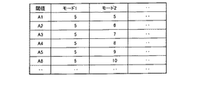
本実施形態の笑顔検出ゲームは、X人の被写体Aの笑顔の撮影が完了するまでの時間を競うものであり、X人以上の大人数が集まっているパーティー等の場面において遊技できる。以下、図3に示すフローチャートを参照して、この笑顔検出ゲームの流れについて説明する。図3に示すフローチャートは、ユーザがゲームの実行開始を指示したタイミングで開始となり、この笑顔検出ゲームプログラムはステップS11の処理に進む。なお笑顔検出ゲーム開始時、ユーザはメニュー操作部34を操作することにより笑顔を撮影する被写体Aの人数Xを設定すると共に、モード設定部32を操作することにより後述するステップS16において笑顔度の判定に用いる閾値が撮影人数に関係なく一定であるモード1と撮影人数に応じて笑顔度の判定に用いる閾値が変化するモード2との間で笑顔検出ゲームのモードを選択する(詳しくは図6を参照して後述する)。
[Smile detection game]
The smile detection game of the present embodiment competes for the time required to complete the shooting of smiles of X subjects A, and can be played in a scene such as a party where a large number of X or more people are gathered. The flow of this smile detection game will be described below with reference to the flowchart shown in FIG. The flowchart shown in FIG. 3 starts at the timing when the user instructs to start the game, and the smile detection game program proceeds to the process of step S11. At the start of the smile detection game, the user operates the
ステップS11の処理では、制御部14が、撮影が完了した被写体Aの人数を計数するためのプログラムカウンタNの値及びタイマー12bの値を「0」に初期化し、図4(a)に示すような撮影が完了した被写体Aの人数N,ユーザにより設定された被写体Aの撮影人数X,タイマ12bのカウント値TB、及びステップS17の処理において用いる閾値を示すデータセットを一次記録装置20内に記憶する。これにより、ステップS11の処理は完了し、笑顔検出ゲームプログラムはステップS12の処理に進む。
In the process of step S11, the
ステップS12の処理では、制御部14が、プログラムカウンタNの値がユーザにより設定された被写体Aの撮影人数X以上であるか否かを判別する。判別の結果、プログラムカウンタNの値が被写体Aの撮影人数X以上である場合、制御部14は、X人の撮影動作が完了したと判断し、笑顔検出ゲームプログラムをステップS24の処理に進める。一方、プログラムカウンタNの値が被写体Aの撮影人数X未満である場合には、制御部14は、X人の撮影動作が完了していないと判断し、笑顔検出ゲームプログラムをステップS13の処理に進める。
In the process of step S12, the
ステップS13の処理では、計時部7が、タイマ12b(タイマTB)を作動させることにより、撮影動作の待機を指示されてから実際に撮影動作が行われるまでの経過時間の計時を開始する。なおこの段階では一次記録装置20内に記憶されているデータセットは図4(b)に示すようになり、タイマ12bのカウント値TB(この場合は5秒)のみが計時部7により随時更新されていく。これにより、ステップS13の処理は完了し、笑顔検出ゲームプログラムはステップS14の処理に進む。
In the process of step S13, the
ステップS14の処理では、制御部14が、メイン表示制御部8を制御することによりメイン表示部41にスルー画像を表示すると共に、スルー画像の輝度信号Y(輝度画像)を特殊演算部11に出力する。これにより、ステップS14の処理は完了し、笑顔検出ゲームプログラムはステップS15の処理に進む。
In the process of step S <b> 14, the
ステップS15の処理では、特殊演算部11が、ステップS14の処理により入力された輝度画像から被写体Aの顔画像を検出する(顔検出処理)。なお2回目の撮影動作以後において以前の撮影動作において撮影された顔画像と酷似する顔画像が検出された場合、制御部14はメイン表示制御部8や音処理部9を制御することにより他の被写体の撮影動作を行うことをユーザに促す警告情報を出力することが望ましい。これにより、ステップS15の処理は完了し、笑顔検出ゲームプログラムはステップS16の処理に進む。
In the process of step S15, the
ステップS16の処理では、特殊演算部11が、ステップS15の処理により検出された顔画像用いて被写体Aの笑顔度を検出する(笑顔検出処理)。これにより、ステップS16の処理は完了し、笑顔検出ゲームプログラムはステップS17の処理に進む。
In the process of step S16, the
ステップS17の処理では、制御部14が、ステップS16の処理により検出された笑顔度が所定の閾値以上であるか否かを判別する。判別の結果、笑顔度が所定の閾値未満である場合、制御部14は、被写体Aの笑顔が検出されていないと判断し、笑顔検出ゲームプログラムをステップS14の処理に戻す。一方、笑顔度が所定の閾値以上である場合には、制御部14は、被写体Aの笑顔が検出されたと判断し、笑顔検出ゲームプログラムをステップS18の処理に進める。なお本実施形態では、笑顔度の判定に用いる閾値は、図5に示すような、撮影の順番N(N=1,2,…)に関係なく閾値ANが一定(図5に示す例では定数“5”)であるモード1と、撮影の順番Nが後になるほど閾値ANが増加(図5に示す例では5,6,7,8,9,10の順に増加)するモード2等、モード毎に閾値ANが規定したテーブルを制御部14が参照することにより予め設定される。また笑顔度が所定時間以上所定の閾値以上にならない場合、制御部14はメイン表示部41や音出力部42を介して撮影条件をユーザに報知するようにしてもよい。
In the process of step S17, the
ステップS18の処理では、制御部14が、DRAMに書込まれている輝度及び色差信号をDRAMインタフェースを介してY,Cb,Crの各コンポーネント毎に読出して画像圧縮部15に書込み、画像処理部15でデータ圧縮する。また計時部7がタイマ12bの作動を停止する。これにより、ステップS18の処理は完了し、笑顔検出ゲームプログラムはステップS19の処理に進む。
In the process of step S18, the
ステップS19の処理では、制御部14が、ステップS18の処理により得られた符号データを画像圧縮部15から読出し、読み出された符号データを撮影画像データとしてタイマ12bの計時時間とを関連付けして記録領域5に記憶する。具体的には、制御部14は、図6に示すようにEXIF形式の撮影画像データの付加情報(EXIF情報)にタイマ12bの計時時間を記録することにより、撮影画像データとタイマ12bの計時時間とを関連付けして記録する。なおこの段階では一次記録装置20内に記憶されているデータセットは図4(c)に示すようになり、タイマ12bのカウント値は撮影動作の待機を指示されてから実際に撮影動作が完了するまでの経過時間となる。これにより、ステップS19の処理は完了し、笑顔検出ゲームプログラムはステップS20の処理に進む。
In the process of step S19, the
ステップS20の処理では、制御部14が、プログラムカウンタNの値を1増数する。これにより、ステップS20の処理は完了し、笑顔検出ゲームプログラムはステップS21の処理に進む。
In the process of step S20, the
ステップS21の処理では、計時部7がタイマ12aによる計時を開始し、制御部14が次のステップS16の処理において用いる閾値を設定する。これにより、ステップS21の処理は完了し、笑顔検出ゲームプログラムはステップS22の処理に進む。
In the process of step S21, the
ステップS22の処理では、制御部14が、タイマ12aの計時時間が所定時間(本実施形態では5秒)以上になったか否かを判別する。そしてタイマ12aの計時時間が所定時間以上になったタイミングで制御部14は笑顔検出ゲームプログラムをステップS23の処理に進める。
In the process of step S22, the
ステップS23の処理では、計時部7がタイマ12a,12bのカウント値を0にリセットし、制御部14がメイン表示制御部8や音処理部9を制御することにより“次の人の笑顔を撮影して下さい”等の次の撮影動作をユーザに促すメッセージを出力する。この段階では一次記録装置20内に記憶されているデータセットは図4(d)や図4(e)に示すようになり、プログラムカウンタN,タイマ12bのカウント値TB,及び閾値の値が更新される。これにより、ステップS23の処理は完了し、笑顔検出ゲームプログラムはステップS24の処理に進む。
In the process of step S23, the
ステップS24の処理では、制御部14が、図7に示すようなX人の被写体Aに対する撮影処理による総得点を計算する。具体的には、制御部14は、図8に示すような撮影動作の待機を指示されてから実際に撮影動作が完了するまでの経過時間と点数とを対応付けしたテーブルを参照して、撮影動作の待機を指示されてから実際に撮影動作が完了するまでの経過時間に対応する点数を各被写体A毎に算出する。そして制御部14は、算出された点数と被写体画像の笑顔度に予め設定された重み係数を乗算した値との和を各被写体A毎に算出し、算出された値の合計値を総得点として出力する。なお本実施形態では、制御部14は、撮影動作の待機を指示されてから実際に撮影動作が完了するまでの経過時間と笑顔度の双方を用いて得点を計算しているが、得点の計算方法は本実施形態に限定されることはなく、どちらか一方を用いて計算するようにしてもよい。これにより、ステップS24の処理は完了し、笑顔検出ゲームプログラムはステップS25の処理に進む。
In the process of step S24, the
ステップS25の処理では、制御部14が、ステップS24の処理により算出された総得点を保存記録装置21に記録する。これにより、ステップS25の処理は完了し、笑顔検出ゲームプログラムはステップS26の処理に進む。
In the process of step S25, the
ステップS26の処理では、制御部14が、メイン表示制御部8を制御することにより、例えば図9に示すような形態でステップS24の処理により算出された総得点をメイン表示部41に出力する。なお図9に示す例では、総得点に関する情報に加えて、撮影動作の待機を指示されてから実際に撮影動作が完了するまでの経過時間と得点が被写体毎に表示されている。またこの処理の際、制御部14は、メイン表示制御部8を制御することにより、図10に示すように今回の笑顔検出ゲームのランキングをメイン表示部41に表示したり、図11に示すようにX人の被写体のうち最も得点が高い被写体の画像をメイン表示部41に表示したりしてもよい。これにより、ステップS26の処理は完了し、笑顔検出ゲームプログラムはステップS27の処理に進む。
In the process of step S26, the
ステップS27の処理では、制御部14が、ステップS24の処理により算出された総得点が所定の得点以上であるか否かを判別する。そして判別の結果、総得点が所定の特定未満である場合、制御部14は一連の笑顔検出ゲームプログラムを終了する。一方、総得点が所定の得点以上である場合には、制御部14は笑顔検出ゲームプログラムをステップS28の処理に進める。
In the process of step S27, the
ステップS28の処理では、制御部14が、例えばマクロ撮影モード等の撮影モードを1つ増やす等、高得点を取得したボーナスとして所定処理を実行する。これにより、ステップS28の処理は完了し、一連の笑顔検出ゲームプログラムは終了する。
In the process of step S28, the
以上の説明から明らかなように、本発明の実施形態となる笑顔検出ゲームプログラムによれば、撮影動作の待機を指示されてから実際に撮影動作が行われるまでの経過時間に基づいた今までにない新規なゲームアプリケーションを提供することができる。また本発明の実施形態となる笑顔検出ゲームプログラムによれば、制御部14が、シャッターボタンの押下操作又はタイマ12aのカウント完了に応じて撮影動作の待機を指示し、タイマ12bの計時動作完了時又は撮影画像の記録動作完了時にタイマ12aのカウントを開始し、タイマ12aのカウント動作完了に応じて撮影動作の待機を指示するので、連続した撮像処理においても撮像処理毎に撮影動作の待機を指示されてから実際に撮影動作が行われるまでの経過時間を記録することができる。本発明の実施形態となる笑顔検出ゲームプログラムによれば、制御部14が、EXIF形式の撮影画像データの付加情報にタイマ12bの計時時間を記録することにより、撮影画像データとタイマ12bの計時時間とを関連付けして記録するので、撮影画像と共に記録されている経過時間を所望の用途に容易に利用することができる。
As is clear from the above description, according to the smile detection game program according to the embodiment of the present invention, based on the elapsed time from when the standby of the shooting operation is instructed until when the shooting operation is actually performed, No new game application can be provided. Further, according to the smile detection game program according to the embodiment of the present invention, the
なお本実施形態では、X人の被写体Aの笑顔を撮影する等の撮影条件をユーザ側で設定することとしたが、笑顔検出ゲームプログラム側で撮影条件を設定してメイン表示部41や音出力部42を介して設定した条件をユーザに報知するようにしてもよい。具体的には、笑顔検出ゲームプログラムは、乱数を発生させるプログラムを利用して図12(a)や図12(b)に示すように同時に撮影する被写体Aの人数や配置を撮影条件として指定するようにしてもよいし、図12(c)や図12(d)に示すように撮影する被写体Aの性別,年齢(大人と子供),及び配置を撮影条件として指定するようにしてもよい。撮影された被写体Aの性別や年齢が設定した撮影条件に適合しているか否かは本願発明の出願時点で公知な顔検出技術を利用することにより判定できる。また複数人の被写体を撮影する場合において、笑顔度が閾値以下の被写体が存在する際には、制御部14は、音出力部42を制御することにより“右から2番目の人もっと笑って下さい”等の笑顔を促すメッセージを出力するようにしてもよい。またこの際、制御部14は、音出力部42を制御することにより笑顔度が高い被写体を褒めるメッセージを出力するようにしてもよい。このような笑顔検出ゲームプログラムによれば、より高度で楽しいゲームアプリケーションを提供することができる。
In this embodiment, the user sets shooting conditions such as shooting X smiles of the subject A. However, the shooting conditions are set on the smile detection game program side, and the
以上、本発明者によってなされた発明を適用した実施の形態について説明したが、この実施の形態による本発明の開示の一部をなす論述及び図面により本発明は限定されることはない。すなわち、上記実施の形態に基づいて当業者等によりなされる他の実施の形態、実施例及び運用技術等は全て本発明の範疇に含まれることは勿論であることを付け加えておく。 As mentioned above, although the embodiment to which the invention made by the present inventor is applied has been described, the present invention is not limited by the description and the drawings that form part of the disclosure of the present invention according to this embodiment. That is, it should be added that other embodiments, examples, operation techniques, and the like made by those skilled in the art based on the above embodiments are all included in the scope of the present invention.
本発明は、デジタルカメラ、ビデオカメラ、携帯電話を含む撮像装置並びにこの撮像装置を利用したゲーム装置に適用することができる。 The present invention can be applied to an imaging device including a digital camera, a video camera, a mobile phone, and a game device using the imaging device.
1:デジタルスチルカメラ
2:撮像光学部
3:撮像部
4:情報処理領域
5:記録領域
6:操作入力領域
7:計時部
8:メイン表示制御部
9:音処理部
11:特殊演算部
12a,12b:タイマ
13:撮像処理部
14:制御部
15:画像圧縮部
20:一時記録装置
21:保存記録装置
22:外部記録装着部
23:外部記録装置
30:撮影指示部
31:決定指示部
32:モード設定部
33:移動操作部
34:メニュー操作部
35:電源操作部
41:メイン表示部
42:音出力部
1: digital still camera 2: imaging optical unit 3: imaging unit 4: information processing region 5: recording region 6: operation input region 7: timing unit 8: main display control unit 9: sound processing unit 11: special calculation unit 12a, 12b: timer 13: imaging processing unit 14: control unit 15: image compression unit 20: temporary recording device 21: storage recording device 22: external recording mounting unit 23: external recording device 30: imaging instruction unit 31: determination instruction unit 32: Mode setting unit 33: movement operation unit 34: menu operation unit 35: power operation unit 41: main display unit 42: sound output unit
Claims (9)
記録手段と、
前記撮像手段による撮影動作の待機を指示する指示手段と、
前記指示手段により撮影動作の待機を指示された後に前記被写体の所定状態を検出する検出手段と、
前記指示手段により撮影動作の待機を指示されてから前記検出手段により前記被写体の所定状態を検出するまでの経過時間を計時する計時手段と、
前記検出手段により前記被写体の所定状態が検出されたタイミングで前記撮像手段に撮影動作の実行を指示し、撮像手段により撮影された前記被写体の画像と前記計時手段により計時された経過時間とを関連付けして前記記録手段に記録する制御手段と
を備えることを特徴とする撮像装置。 Imaging means for photographing a subject;
Recording means;
Instruction means for instructing standby of a photographing operation by the imaging means ;
Detection means for detecting a predetermined state of the object after being instructed to wait for photographing operation by the pre-Symbol instruction means,
Time measuring means for measuring an elapsed time from when the instruction means is instructed to wait for a photographing operation to when the detection means detects the predetermined state of the subject;
The imaging unit is instructed to perform a shooting operation at a timing when the predetermined state of the subject is detected by the detection unit, and the image of the subject captured by the imaging unit is associated with the elapsed time measured by the timing unit. And a control means for recording in the recording means.
前記記録手段に前記画像に関連付けて記録されている経過時間に応じて第1の所定処理を実行する第1の処理実行手段とFirst process execution means for executing a first predetermined process in accordance with an elapsed time recorded in association with the image on the recording means;
を備えることを特徴とする撮像装置。An imaging apparatus comprising:
前記被写体は人の顔であり、前記被写体の所定状態は人の顔の笑顔に係る状態であることを特徴とする撮像装置。 In the imaging device according to claim 1 or 2 ,
The imaging apparatus according to claim 1, wherein the subject is a human face, and the predetermined state of the subject is a state relating to a smile on the human face.
前記第1の所定処理は、前記撮像手段により撮影された前記複数の被写体の画像各々に関連付けて記録されている経過時間に応じて得点を計算することを特徴とする撮像装置。 The imaging device according to claim 2 ,
The imaging apparatus according to claim 1, wherein the first predetermined process calculates a score according to an elapsed time recorded in association with each of the plurality of subject images photographed by the imaging means.
前記第1の処理実行手段により計算された各画像の得点に応じて第2の所定処理を実行する第2の処理実行手段とSecond process execution means for executing a second predetermined process in accordance with the score of each image calculated by the first process execution means;
を備えることを特徴とする撮像装置。An imaging apparatus comprising:
前記第1の所定処理は、複数のゲーム参加者のそれぞれについて得点を計算し、The first predetermined process calculates a score for each of a plurality of game participants,
前記第2の所定処理は、前記得点を利用したゲームであることを特徴とする撮像装置。The imaging apparatus, wherein the second predetermined process is a game using the score.
シャッターボタンの押下操作又はタイマのカウント完了に応じて、前記指示手段に対し前記撮像手段による撮影動作の待機を指示する第1の指示制御手段と、
前記計時手段の計時動作完了時又は前記制御手段の記録動作完了時に前記タイマのカウントを開始するカウント手段と、
前記カウント手段のカウント動作完了に応じて、前記指示手段に対し前記撮像手段による撮影動作の待機を指示する第2の指示制御手段と
を備えることを特徴とする撮像装置。 The imaging apparatus according to any one of claims 1 to 6,
In response to the pressing operation or count completion timer of the shutter button, the first instruction control means for instructing the stand-shooting operation by the shooting image means to said instruction means,
Counting means for starting counting of the timer upon completion of the timing operation of the timing means or upon completion of the recording operation of the control means;
It said counting means in response to the counting operation completion, the imaging apparatus characterized by comprising a second indication control means for instructing the stand-shooting operation by the shooting image means to said instruction means.
前記制御手段は、前記被写体の画像データの付加情報領域に前記計時手段により計時された経過時間を記録することにより、前記被写体の画像と前記経過時間とを関連付けして記録手段に記録することを特徴とする撮像装置。 The imaging device according to any one of claims 1 to 7 ,
The control means records the elapsed time measured by the time measuring means in the additional information area of the image data of the subject so as to associate and record the image of the subject and the elapsed time on the recording means. An imaging device that is characterized.
前記撮像処理の実行の待機を指示された後に前記被写体の所定状態を検出する検出処理と、
前記撮像処理の実行の待機を指示されてから前記検出処理による前記被写体の所定状態を検出までの経過時間を計時する計時処理と、
前記検出処理により前記被写体の所定状態が検出されたタイミングで前記撮像処理の実行を指示し、前記撮像処理により撮影された前記被写体の画像と前記計時処理により計時された経過時間とを関連付けして記録手段に記録する制御処理と
をコンピュータに実行させることを特徴とするコンピュータプログラム。 Imaging processing to photograph the subject ;
A detection process for detecting a predetermined state of the object after being instructed to wait for execution of the pre-Symbol imaging process,
A time counting process for measuring an elapsed time from when the standby for execution of the imaging process is instructed until detection of the predetermined state of the subject by the detection process;
Instructing the execution of the imaging process at a timing when the predetermined state of the subject is detected by the detection process, and associating the image of the subject imaged by the imaging process with the elapsed time measured by the timing process A computer program for causing a computer to execute control processing recorded in a recording means.
Priority Applications (1)
| Application Number | Priority Date | Filing Date | Title |
|---|---|---|---|
| JP2009001455A JP5407338B2 (en) | 2009-01-07 | 2009-01-07 | Imaging apparatus and computer program |
Applications Claiming Priority (1)
| Application Number | Priority Date | Filing Date | Title |
|---|---|---|---|
| JP2009001455A JP5407338B2 (en) | 2009-01-07 | 2009-01-07 | Imaging apparatus and computer program |
Publications (3)
| Publication Number | Publication Date |
|---|---|
| JP2010161537A JP2010161537A (en) | 2010-07-22 |
| JP2010161537A5 JP2010161537A5 (en) | 2012-01-05 |
| JP5407338B2 true JP5407338B2 (en) | 2014-02-05 |
Family
ID=42578388
Family Applications (1)
| Application Number | Title | Priority Date | Filing Date |
|---|---|---|---|
| JP2009001455A Expired - Fee Related JP5407338B2 (en) | 2009-01-07 | 2009-01-07 | Imaging apparatus and computer program |
Country Status (1)
| Country | Link |
|---|---|
| JP (1) | JP5407338B2 (en) |
Families Citing this family (2)
| Publication number | Priority date | Publication date | Assignee | Title |
|---|---|---|---|---|
| JP7348548B2 (en) | 2021-12-24 | 2023-09-21 | キヤノンマーケティングジャパン株式会社 | Information processing system, information processing method, program |
| JP7436878B2 (en) | 2021-12-24 | 2024-02-22 | キヤノンマーケティングジャパン株式会社 | Information processing system, information processing method, program |
Family Cites Families (3)
| Publication number | Priority date | Publication date | Assignee | Title |
|---|---|---|---|---|
| JP2000125165A (en) * | 1998-10-15 | 2000-04-28 | Minolta Co Ltd | Digital camera |
| JP4197019B2 (en) * | 2006-08-02 | 2008-12-17 | ソニー株式会社 | Imaging apparatus and facial expression evaluation apparatus |
| JP4742316B2 (en) * | 2006-08-24 | 2011-08-10 | カシオ計算機株式会社 | Imaging apparatus, imaging method, and imaging control program |
-
2009
- 2009-01-07 JP JP2009001455A patent/JP5407338B2/en not_active Expired - Fee Related
Also Published As
| Publication number | Publication date |
|---|---|
| JP2010161537A (en) | 2010-07-22 |
Similar Documents
| Publication | Publication Date | Title |
|---|---|---|
| KR100700336B1 (en) | Image pickup device, image pickup method and recording medium | |
| JP4645685B2 (en) | Camera, camera control program, and photographing method | |
| JP4853932B2 (en) | Imaging apparatus and program | |
| JP5401420B2 (en) | Imaging device | |
| US7889269B2 (en) | Image taking device and control method for image taking | |
| JP5888614B2 (en) | IMAGING DEVICE, VIDEO CONTENT GENERATION METHOD, AND PROGRAM | |
| JP2010226702A (en) | Imaging apparatus | |
| JP5407338B2 (en) | Imaging apparatus and computer program | |
| JP2007228453A (en) | Imaging apparatus, reproduction device, program, and storage medium | |
| JP2012257112A (en) | Imaging apparatus and program | |
| JP5320795B2 (en) | Imaging device | |
| JP2010087598A (en) | Photographic apparatus, photographic control method and program therefor, image display apparatus, image display method and program therefor, and photographic system, control method therefor and program therefor | |
| JP2005094133A (en) | Photographing apparatus | |
| JP2014007454A (en) | Image pickup device and image pickup method | |
| JP5170217B2 (en) | Camera, camera control program, and photographing method | |
| JP2010148049A (en) | Image reproducing system and camera | |
| JP2003230090A (en) | Electronic camera | |
| JP2014120926A (en) | Imaging apparatus | |
| JP4968367B2 (en) | Imaging apparatus, imaging assistance method, and program | |
| JP2005333461A (en) | Camera, and recording method and recording/reproducing method of the camera | |
| JP2007074276A (en) | Imaging apparatus | |
| JP2006262128A (en) | Digital camera | |
| JP2006314136A (en) | Photographic device and photographing method | |
| JP2005218126A (en) | Photographing device and photographing method | |
| JP2006101373A (en) | Image pickup device, image pickup auxiliary method, and program |
Legal Events
| Date | Code | Title | Description |
|---|---|---|---|
| A621 | Written request for application examination |
Free format text: JAPANESE INTERMEDIATE CODE: A621 Effective date: 20111107 |
|
| A521 | Request for written amendment filed |
Free format text: JAPANESE INTERMEDIATE CODE: A523 Effective date: 20111110 |
|
| A977 | Report on retrieval |
Free format text: JAPANESE INTERMEDIATE CODE: A971007 Effective date: 20121122 |
|
| A131 | Notification of reasons for refusal |
Free format text: JAPANESE INTERMEDIATE CODE: A131 Effective date: 20121219 |
|
| A521 | Request for written amendment filed |
Free format text: JAPANESE INTERMEDIATE CODE: A523 Effective date: 20130125 |
|
| A131 | Notification of reasons for refusal |
Free format text: JAPANESE INTERMEDIATE CODE: A131 Effective date: 20130604 |
|
| A521 | Request for written amendment filed |
Free format text: JAPANESE INTERMEDIATE CODE: A523 Effective date: 20130712 |
|
| TRDD | Decision of grant or rejection written | ||
| A01 | Written decision to grant a patent or to grant a registration (utility model) |
Free format text: JAPANESE INTERMEDIATE CODE: A01 Effective date: 20131008 |
|
| A61 | First payment of annual fees (during grant procedure) |
Free format text: JAPANESE INTERMEDIATE CODE: A61 Effective date: 20131021 |
|
| R150 | Certificate of patent or registration of utility model |
Ref document number: 5407338 Country of ref document: JP Free format text: JAPANESE INTERMEDIATE CODE: R150 |
|
| LAPS | Cancellation because of no payment of annual fees |