JP5406063B2 - Reconstruction calculation device, reconstruction calculation method, and X-ray CT apparatus - Google Patents
Reconstruction calculation device, reconstruction calculation method, and X-ray CT apparatus Download PDFInfo
- Publication number
- JP5406063B2 JP5406063B2 JP2010015030A JP2010015030A JP5406063B2 JP 5406063 B2 JP5406063 B2 JP 5406063B2 JP 2010015030 A JP2010015030 A JP 2010015030A JP 2010015030 A JP2010015030 A JP 2010015030A JP 5406063 B2 JP5406063 B2 JP 5406063B2
- Authority
- JP
- Japan
- Prior art keywords
- reconstruction
- image
- projection data
- forward projection
- ray
- Prior art date
- Legal status (The legal status is an assumption and is not a legal conclusion. Google has not performed a legal analysis and makes no representation as to the accuracy of the status listed.)
- Expired - Fee Related
Links
- 238000004364 calculation method Methods 0.000 title claims description 48
- 238000000034 method Methods 0.000 claims description 176
- 230000008569 process Effects 0.000 claims description 103
- 238000012545 processing Methods 0.000 claims description 55
- 238000003384 imaging method Methods 0.000 claims description 26
- 238000012937 correction Methods 0.000 description 17
- 238000003745 diagnosis Methods 0.000 description 9
- 238000003860 storage Methods 0.000 description 7
- 230000006872 improvement Effects 0.000 description 6
- 238000001514 detection method Methods 0.000 description 4
- 238000007476 Maximum Likelihood Methods 0.000 description 3
- 238000010894 electron beam technology Methods 0.000 description 3
- 238000004458 analytical method Methods 0.000 description 2
- 230000005540 biological transmission Effects 0.000 description 2
- 238000006243 chemical reaction Methods 0.000 description 2
- 238000000605 extraction Methods 0.000 description 2
- 230000003902 lesion Effects 0.000 description 2
- 230000007480 spreading Effects 0.000 description 2
- 238000003892 spreading Methods 0.000 description 2
- 208000029343 Schaaf-Yang syndrome Diseases 0.000 description 1
- 210000001015 abdomen Anatomy 0.000 description 1
- 238000010521 absorption reaction Methods 0.000 description 1
- 230000002238 attenuated effect Effects 0.000 description 1
- 230000008901 benefit Effects 0.000 description 1
- 230000015572 biosynthetic process Effects 0.000 description 1
- 230000003111 delayed effect Effects 0.000 description 1
- 230000006866 deterioration Effects 0.000 description 1
- 238000011161 development Methods 0.000 description 1
- 238000010586 diagram Methods 0.000 description 1
- 238000009826 distribution Methods 0.000 description 1
- 230000000694 effects Effects 0.000 description 1
- 238000005516 engineering process Methods 0.000 description 1
- 230000006870 function Effects 0.000 description 1
- 238000003702 image correction Methods 0.000 description 1
- 230000010354 integration Effects 0.000 description 1
- 230000001678 irradiating effect Effects 0.000 description 1
- 239000004973 liquid crystal related substance Substances 0.000 description 1
- 239000011159 matrix material Substances 0.000 description 1
- 238000012986 modification Methods 0.000 description 1
- 230000004048 modification Effects 0.000 description 1
- 238000009206 nuclear medicine Methods 0.000 description 1
- 238000012805 post-processing Methods 0.000 description 1
- 238000007781 pre-processing Methods 0.000 description 1
- 229910052704 radon Inorganic materials 0.000 description 1
- SYUHGPGVQRZVTB-UHFFFAOYSA-N radon atom Chemical compound [Rn] SYUHGPGVQRZVTB-UHFFFAOYSA-N 0.000 description 1
Images


Landscapes
- Apparatus For Radiation Diagnosis (AREA)
- Image Processing (AREA)
- Image Analysis (AREA)
Description
本発明は、逐次近似法を利用したX線CT画像の再構成演算処理に関する。 The present invention relates to an X-ray CT image reconstruction calculation process using a successive approximation method.
X線CT装置は、被検体の周囲からX線を照射し、被検体を透過したX線の強度に関するデータをX線検出器にて収集し、収集したデータに基づいて被検体内部のX線吸収係数の分布情報を画像化する装置である。 The X-ray CT apparatus irradiates X-rays from around the subject, collects data relating to the intensity of the X-rays transmitted through the subject, and collects X-rays inside the subject based on the collected data. This is an apparatus for imaging distribution information of absorption coefficients.
画像の再構成法には、大別して、解析的再構成法と代数的再構成法とがある。これらの画像再構成法のうち解析的再構成法には、例えばフーリエ変換法、フィルタ補正逆投影法(Filtered Back Projection;以下、FBP法という)、重畳積分法があり、代数的再構成法には、例えばMLEM(Maximum Likelihood Expectation Maximization)法やOSEM(Ordered Subset Expectation Maximization)法に代表される逐次近似再構成法がある。このうち、現在実用化されている解析的再構成法は、広いコーン角(X線ビームのスライス方向への広がり角)を有したマルチスライスCTへ適用すると、再構成アルゴリズムの不完全性によりコーンビームアーチファクトを生じるという問題がある。一方、代数的再構成法は、解析的再構成法と比較して完全性が高いことが知られているが、その反面、再帰的演算を行うために計算時間が長大となる。このため代数的再構成法は、従来は核医学画像の分野では用いられており、X線CT画像の分野では普及していなかった。しかし、逐次近似再構成法(代数的再構成法)の計算時間についての問題は、近年のコンピュータ技術の発達により解決されつつあり、X線CT装置の画像形成に逐次近似再構成法を用いて画質改善を行うことが特許文献1に開示されている。 Image reconstruction methods are roughly classified into an analytical reconstruction method and an algebraic reconstruction method. Among these image reconstruction methods, analytical reconstruction methods include, for example, a Fourier transform method, a filtered back projection method (hereinafter referred to as FBP method), and a superposition integration method. For example, there is a successive approximation reconstruction method represented by the MLEM (Maximum Likelihood Extraction Maximization) method and the OSEM (Ordered Subset Extraction Maximization) method. Among them, the analytical reconstruction method currently in practical use is applied to a multi-slice CT having a wide cone angle (expansion angle in the slice direction of the X-ray beam), and the reconstruction algorithm is incomplete due to the incompleteness of the reconstruction algorithm. There is a problem of generating beam artifacts. On the other hand, it is known that the algebraic reconstruction method has higher completeness than the analytical reconstruction method, but on the other hand, a recursive operation requires a long calculation time. For this reason, the algebraic reconstruction method has been conventionally used in the field of nuclear medicine images and has not spread in the field of X-ray CT images. However, the problem of the calculation time of the successive approximation reconstruction method (algebraic reconstruction method) is being solved by the recent development of computer technology, and the successive approximation reconstruction method is used for image formation of an X-ray CT apparatus. Japanese Patent Application Laid-Open No. 2004-228561 discloses that image quality is improved.
特許文献1では、上述のFBP法を用いた画像の再構成処理が行われた後、関心領域(ROI)について再構成画像の画質を改善するために、後処理としてOSEM法を用いた画質改善処理が行われる。画質改善処理は再投影画像と投影画像とを同一角度で比較した比較画像を作成し、比較画像の標準偏差SDを算出し、この標準偏差SDの大きさによって更に画質改善が必要か否かを判定し、終了条件を満たすまで画質改善の処理を繰り返すものである。
In
しかしながら、上述の特許文献1のように、FBP法による画像の再構成処理後にOSEM法(逐次近似再構成法)を用いた画質改善処理を行うと、FBP法で用いた再構成フィルタの効果が損なわれてしまう。例えば、医師等の診断には所定の周波数特性を有する画像等が要求される場合もあるが、上述のFBP法で採用した再構成フィルタによって調整した周波数特性は、その後のOSEM法によって損なわてしまう。
However, if the image quality improvement processing using the OSEM method (sequential approximation reconstruction method) is performed after the image reconstruction processing by the FBP method as in
本発明は、以上の問題点に鑑みてなされたものであり、医用診断に有効なX線CT画像を、より高速かつより正確に作成することが可能な再構成演算装置、再構成演算方法、及びX線CT装置を提供することを目的としている。 The present invention has been made in view of the above problems, and a reconstruction calculation device, a reconstruction calculation method, and an X-ray CT image that are effective for medical diagnosis can be created more quickly and more accurately. And an X-ray CT apparatus.
前述した目的を達成するために第1の発明は、所定のスキャン軌跡による撮影にて取得したX線投影データに対して逐次近似処理を含む再構成処理を行い、第1画像を生成する第1の再構成手段と、前記第1画像を順投影することにより順投影データを生成する順投影データ生成手段と、前記順投影データに対して、所望の再構成条件を設定した解析的な再構成処理を行い、最終画像を再構成する第2の再構成手段と、を備え、前記順投影データ生成手段は、前記撮影と比較して、前記第2の再構成手段の再構成処理におけるアーチファクトの混入が少ないスキャン軌跡で、前記第1画像を順投影することを特徴とする再構成演算装置である。 In order to achieve the above-described object, the first invention performs a reconstruction process including a successive approximation process on X-ray projection data acquired by imaging with a predetermined scan locus, and generates a first image. Reconstructing means, forward projection data generating means for generating forward projection data by forward projecting the first image, and analytical reconstruction in which desired reconstruction conditions are set for the forward projection data A second reconstructing unit that performs processing and reconstructs a final image, and the forward projection data generating unit includes artifacts in the reconstructing process of the second reconstructing unit as compared with the photographing. The reconstruction calculation device is characterized in that the first image is projected in a forward direction with a scan trajectory with little mixing.
第2の発明は、所定のスキャン軌跡による撮影にて取得したX線投影データに対して逐次近似処理を含む再構成処理を行い、第1画像を生成する第1の再構成ステップと、前記第1画像を順投影することにより順投影データを生成する順投影データ生成ステップと、前記順投影データに対して、所望の再構成条件を設定した解析的な再構成処理を行い、最終画像を再構成する第2の再構成ステップと、を含み、前記順投影データ生成ステップにおいて、前記撮影と比較して、前記第2の再構成手段の再構成処理におけるアーチファクトの混入が少ないスキャン軌跡で、前記第1画像を順投影することを特徴とする再構成演算方法である。 According to a second aspect of the present invention, there is provided a first reconstruction step of performing a reconstruction process including a successive approximation process on X-ray projection data acquired by imaging with a predetermined scan locus to generate a first image; A forward projection data generation step for generating forward projection data by forward projecting one image, and an analytical reconstruction process in which a desired reconstruction condition is set are performed on the forward projection data, and the final image is reconstructed. A scan trajectory in which less artifacts are mixed in the reconstruction process of the second reconstruction means in the forward projection data generation step than in the imaging in the forward projection data generation step, The reconstruction calculation method is characterized by forwardly projecting a first image.
第3の発明は、被検体周囲の複数角度方向から被検体に対してX線を照射し、被検体を透過したX線投影データを収集するスキャナと、スキャナにて収集したX線投影データに基づいてX線CT画像を再構成する再構成演算装置と、を備えたX線CT装置であって、前記再構成演算装置は、所定のスキャン軌跡による撮影にて取得した前記X線投影データに対して逐次近似処理を含む再構成処理を行い、第1画像を生成する第1の再構成手段と、前記第1画像を順投影することにより順投影データを生成する順投影データ生成手段と、前記順投影データに対して、所望の再構成条件を設定した解析的な再構成処理を行い、最終画像を再構成する第2の再構成手段と、を備え、前記順投影データ生成手段は、前記撮影と比較して、前記第2の再構成手段の再構成処理におけるアーチファクトの混入が少ないスキャン軌跡で、前記第1画像を順投影することを特徴とするX線CT装置である。 According to a third aspect of the present invention, there is provided a scanner that irradiates a subject with X-rays from a plurality of angular directions around the subject, collects X-ray projection data transmitted through the subject, and X-ray projection data collected by the scanner. An X-ray CT apparatus comprising: a reconstruction calculation device that reconstructs an X-ray CT image based on the X-ray projection data acquired by imaging with a predetermined scan locus. A first reconstruction unit that performs a reconstruction process including a successive approximation process to generate a first image; a forward projection data generation unit that generates forward projection data by forward projecting the first image; A second reconstruction unit configured to perform an analytical reconstruction process in which a desired reconstruction condition is set on the forward projection data and reconstruct a final image, and the forward projection data generation unit includes: Compared to the shooting, the second re- Scan locus contaminated artifacts in the reconstructed process is less adult means is an X-ray CT apparatus characterized by forward projecting the first image.
本発明によれば、医用診断に有効なX線CT画像を、より高速かつ正確に作成することが可能な再構成演算装置、再構成演算方法、及びX線CT装置を提供できる。 ADVANTAGE OF THE INVENTION According to this invention, the reconstruction calculation apparatus, the reconstruction calculation method, and X-ray CT apparatus which can produce the X-ray CT image effective for medical diagnosis more rapidly and correctly can be provided.
以下、添付図面を参照しながら、本発明の好適な実施形態について詳細に説明する。 Hereinafter, preferred embodiments of the present invention will be described in detail with reference to the accompanying drawings.
まず、図1〜図2を参照して、本実施の形態のX線CT装置1の構成について説明する。
なお、本実施形態では、X線CT装置1は、被検体全体をカバーするワイドファンビームを照射しつつX線源とX線検出器とが一体となり回転する回転−回転方式(Rotate−Rotate方式)、電子ビームを電気的に偏向させながらターゲット電極に当てる電子ビーム走査方式(Scanning Electron Beam方式)、その他の方式のものがあるが、本発明はいずれの方式のX線CT装置にも適用可能である。
First, with reference to FIGS. 1-2, the structure of the
In the present embodiment, the
図1及び図2に示すように、X線CT装置1は、スキャナ2、寝台3、操作ユニット4から構成される。X線CT装置1は、寝台3上に固定された被検体6をスキャナ2の開口部に搬入してスキャンすることにより、被検体周囲の各角度(ビュー)方向からそれぞれ投影データを取得する。
As shown in FIGS. 1 and 2, the
スキャナ2は、図2に示すようにX線発生装置(X線源)201、高電圧発生装置22、X線制御装置202、コリメータ203、コリメータ制御装置204、X線検出器205、プリアンプ206、ADコンバータ207、回転板24、駆動装置208、駆動伝達系210、スキャナ制御装置23、及び中央制御装置21から構成される。
As shown in FIG. 2, the scanner 2 includes an X-ray generator (X-ray source) 201, a high-
X線発生装置201はX線源であり、高電圧発生装置22から印加・供給される管電圧・管電流に従った強度のX線を被検体6に対して連続的または断続的に照射する。X線制御装置202は、中央制御装置21により決定された管電圧及び管電流に従って、高電圧発生装置22を制御する。
The
コリメータ203は、X線発生装置201から放射されたX線を、例えばコーンビーム(円錐形または角錐形ビーム)状に成形して被検体6に照射させるものであり、コリメータ制御装置204により制御される。被検体6を透過したX線はX線検出器205に入射する。
The
X線検出器205は、例えばシンチレータとフォトダイオードの組み合わせによって構成されるX線検出素子群をチャネル方向(周回方向)に例えば1000個程度、列方向(体軸方向)に例えば1〜320個程度配列したものであり、被検体6を介してX線発生装置201に対向するように配置される。X線検出器205はX線発生装置201から放射されて被検体6を透過したX線を検出し、検出したX線投影データをプリアンプ206にて増幅した後、A/Dコンバータ207に出力する。
The X-ray detector 205 includes, for example, about 1000 X-ray detection element groups configured by, for example, a combination of a scintillator and a photodiode in the channel direction (circumferential direction), for example, about 1-320 in the column direction (body axis direction). They are arranged and arranged so as to face the
A/Dコンバータ207は、X線検出器205の個々のX線検出素子により検出され、プリアンプ206により増幅されたX線投影データを収集し、ディジタル信号に変換して操作ユニット4の演算装置44に出力する。
The A /
回転板24には、X線発生装置201、コリメータ203、X線検出器205、プリアンプ206等が搭載される。回転板24は、スキャナ制御装置23によって制御される駆動装置208から、駆動伝達系210を通じて伝達される駆動力によって回転される。
On the rotating
中央制御装置21は、CPU(Central Processing Unit)、ROM(Read Only Memory)、RAM(Random Access Memory)等により構成される。中央制御装置21は、X線管制御装置202、コリメータ制御装置204、スキャナ制御装置23、操作ユニット4の演算装置44を制御し、また、寝台3内の寝台制御装置301を制御するものである。
The
図1及び図2に示す寝台3は、寝台制御装置301に制御されて、所定の高さ位置、体軸位置、及び体幅位置に移動される。これにより、被検体6がスキャナ2のX線照射空間に搬入及び搬出される。
The bed 3 shown in FIG. 1 and FIG. 2 is moved to a predetermined height position, body axis position, and body width position under the control of the
操作ユニット4は、表示装置41、入力装置42、記憶装置43、及び演算装置44から構成される。また演算装置44は、再構成演算装置45及び画像処理装置46から構成される。操作ユニット4はスキャナ2に接続される。表示装置41、入力装置42、記憶装置43、及び演算装置44の各部はスキャナ2内の中央制御装置21により制御される。
The operation unit 4 includes a display device 41, an input device 42, a storage device 43, and an
表示装置41は、液晶パネル、CRTモニタ等のディスプレイ装置と、ディスプレイ装置と連携して表示処理を実行するための論理回路で構成され、演算装置44に接続される。表示装置41は、中央制御装置21及び演算装置44の制御によって演算装置44から出力される再構成画像(X線CT画像)並びに中央制御装置21が取り扱う種々の情報を表示するものである。
The display device 41 includes a display device such as a liquid crystal panel and a CRT monitor, and a logic circuit for executing display processing in cooperation with the display device, and is connected to the
入力装置42は、例えば、キーボード、マウス、テンキー等の入力装置、及び各種スイッチボタン等により構成され、操作者によって入力される各種の指示や情報を演算装置44に出力する。演算装置44は、入力装置42から入力された各種指示や情報を中央制御装置21に出力する。操作者は、表示装置41及び入力装置42を使用して対話的にX線CT装置1を操作する。
The input device 42 includes, for example, an input device such as a keyboard, a mouse, and a numeric keypad, and various switch buttons. The input device 42 outputs various instructions and information input by the operator to the
記憶装置43は、ハードディスク等により構成されるものであり、演算装置44に接続される。記憶装置43には、演算装置44から出力された画像や後述する処理に必要なプログラム及び各種データを記憶する。
The storage device 43 is configured by a hard disk or the like, and is connected to the
演算装置44は、CPU、ROM、RAM等により構成され、中央制御装置21の制御に従って操作ユニット4全体を制御する。
再構成演算装置45は、中央制御装置21の制御によってスキャナ2内のA/Dコンバータ207から出力されたX線投影データを取得し、画像の再構成処理を行う。すなわち、再構成演算装置45は、取得したX線投影データに対して、log変換、キャリブレーション等の前処理を行い、更にX線投影データに対して後述する処理(図5参照)を施すことにより、被検体6のX線CT画像を再構成する。再構成されたX線CT画像は、記憶装置43に記憶されるとともに、表示装置41に表示される。画像処理装置46は、再構成演算装置45によって生成されたX線CT画像に対して、操作者の所望する画像加工処理を施す装置である。
The
The
次に、図3を参照してX線検出器205及びX線ビームについて説明する。
X線検出器205には、図3(a)に示すような単列検出器205Aと、図3(b)に示すような多列検出器205Bとがある。
単列検出器205Aは、回転板24の周回方向に1次元(1列)に検出素子を配列したものであり、1次元検出器、シングルスライスとも呼ばれる。
一方、多列検出器205Bは、回転板24の周回方向及び周回軸方向の2次元に検出素子を配置したものであり、2次元検出器、マルチスライスとも呼ばれる。
Next, the X-ray detector 205 and the X-ray beam will be described with reference to FIG.
The X-ray detector 205 includes a single-
The single-
On the other hand, the
単列検出器205Aを搭載したシングルスライスCT装置では、X線発生装置201から扇状に広がるX線ビームが照射される。また、多列検出器205Bを搭載したマルチスライスCT装置では、多列検出器205Bの列数に応じたコーン角を有する円錐状または角錐状に広がるX線ビームが、X線発生装置201から照射される。
In a single slice CT apparatus equipped with the single-
次に、図4を参照してスキャン方式について説明する。
X線CT装置1では、寝台3に載せられた被検体6の周りを、回転板24が回転しながらX線照射が行われる。このとき、図4(a)に示すように、回転板24の周回中は寝台3の位置を変えず、X線源201が被検体6の周りを円軌道を描くようにして周回する撮影のことをノーマルスキャンまたはアキシャルスキャンと呼ぶ。一方、図4(b)に示すように、回転板24の周回中に寝台3の位置を体軸(z)方向に移動させ、X線源201が被検体6の周りをらせん軌道を描くように周回する撮影をらせんスキャンまたはヘリカルスキャンという。
Next, the scanning method will be described with reference to FIG.
In the
本発明のX線CT装置1のX線検出器205は、図3(b)に示す多列検出器205Bを搭載したマルチスライスCT装置である。被検体6を撮影する際、スキャナ2は多列検出器205Bを用い、図4(a)のノーマルスキャンまたは図4(b)のらせんスキャンにてX線投影データを取得する。また、再構成演算装置45は、後述するようにFBP法等によって解析的に再構成したCT画像に対して順投影(再投影)、逆投影を繰り返すことにより第1画像を生成するが、第1画像の生成後に再度順投影処理を行い、この順投影処理による順投影データを用いて所望の再構成条件にて第2の再構成処理を行う。第1画像の生成の順投影処理では、再構成演算装置45は、単列検出器205Aまたは撮影時よりも少ない列数の多列検出器205Bを仮想的に用いたスキャンを行う。
The X-ray detector 205 of the
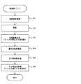
以下、図5のフローチャート及び図6を参照して、X線CT装置1の動作について説明する。
Hereinafter, the operation of the
本実施の形態のX線CT装置1の中央制御装置21は、被検体6の撮影及び画像再構成を行う際に、図5に示すフローチャートの手順で処理を実行する。すなわち、中央制御装置21は、記憶装置43から当該処理に関するプログラム及びデータを読み出し、このプログラム及びデータに基づいて以下の手順で処理を実行する。
The
まず、中央制御装置21は、撮影条件及び再構成条件の設定を受け付ける。撮影条件としては、例えば、寝台移動速度、管電流、管電圧、コリメータ条件、らせんピッチ、スライス位置等が挙げられる。また再構成条件としては、再構成FOV、再構成中心位置、再構成ピッチ(スライス厚)、関心領域、再構成画像マトリクスサイズ、再構成フィルタ関数、逐次近似処理の最大反復回数、収束条件等が挙げられる(ステップS1)。
First, the
操作ユニット4の入力装置42から撮影条件等が入力されると、次に、中央演算装置21は、ステップS1で入力された撮影条件等に基づいて、撮影に必要な制御信号をX線制御装置202、寝台制御装置301、スキャナ制御装置23に送出する。また中央演算装置21は、撮影スタート信号を発し、撮影を開始させる(ステップS2)。
When an imaging condition or the like is input from the input device 42 of the operation unit 4, the
撮影が開始されると、X線制御装置202により高電圧発生装置22に制御信号が送られ、X線発生装置201に高電圧が印加される。X線発生装置201はX線を被検体6に対して照射する。このとき、スキャナ制御装置23から駆動装置208に制御信号が送られ、X線発生装置201、X線検出器205、プリアンプ206等が被検体6の周りに周回される。一方、寝台制御装置301により被検体6を載せた寝台3は、ノーマルスキャン時は、所定のスライス位置で静止し、らせんスキャン時は所定のらせんピッチで体軸方向に平行移動される。
When imaging is started, a control signal is sent to the
X線発生装置201から照射されたX線は、コリメータ203により照射領域を制限され、被検体6内の各組織で吸収(減衰)され、被検体6を通過し、X線検出器205で検出される。X線検出器205で検出されたX線は電流に変換され、プリアンプ206で増幅され、A/Dコンバータ207でディジタルデータに変換されて、操作ユニット4の演算装置44へ出力される。演算装置44は取得したディジタルデータに対してlog変換やキャリブレーションを行い、投影データとする。この投影データは再構成演算装置45による再構成演算の対象となる。
X-rays emitted from the
再構成演算装置45は、投影データを取得すると、まず、第1の再構成処理を行い、第1の再構成画像(以下、第1画像という)を得る(ステップS3)。
この第1の再構成処理において、再構成演算装置45は逐次近似法を含む再構成処理を行う。すなわち、再構成演算装置45は、投影データに対して所定の初期画像を与えて逐次近似法による再構成処理を開始するか、或いは、演算処理の高速化のために、投影データに対して予め解析的再構成法により初期画像を再構成し、この初期画像のノイズやアーチファクトを確認した上で、逐次近似法による再構成処理を開始する。
When acquiring the projection data, the
In the first reconstruction process, the
初期画像を得るための解析的再構成法としては、ラドン変換法、フーリエ変換法、フィルタ補正逆投影法(FBP法)等、どの方法を用いてもよいが、64列程度のX線検出器205を有するマルチスライスCT装置の場合には、例えばWeighted Feldkamp法をベースとしたフィルタ補正3D逆投影処理、或いはこれを改良した処理が好適である。Weighted Feldkamp法をベースとしたフィルタ補正3D逆投影処理を採用した場合には、コーン角を考慮した再構成処理が行われるため、逐次近似処理の収束までの繰り返し回数が少なくなり、演算時間を短縮できる。また、初期画像として、一定値画像を用いてもよい。ただし、一定値画像を用いる場合は、投影データに対する尤度が低い場合が多いので、逐次近似処理の収束が遅くなり演算時間が長大となってしまう。このため、ステップS3の処理の高速化の観点からは、できるだけ投影データに対する尤度の高い初期画像を採用することが望ましい。 As an analytical reconstruction method for obtaining an initial image, any method such as a Radon transform method, a Fourier transform method, a filtered back projection method (FBP method) or the like may be used. In the case of a multi-slice CT apparatus having 205, for example, a filter-corrected 3D backprojection process based on the Weighted Feldkamp method or a process obtained by improving this is suitable. When filter-corrected 3D backprojection processing based on the Weighted Feldkamp method is adopted, reconstruction processing is performed in consideration of the cone angle, so the number of iterations until the successive approximation processing converges is reduced, and the calculation time is reduced. it can. A constant value image may be used as the initial image. However, when a constant value image is used, since the likelihood for projection data is often low, the convergence of the successive approximation process is delayed, and the computation time is long. For this reason, from the viewpoint of speeding up the processing in step S3, it is desirable to employ an initial image with a high likelihood for the projection data as much as possible.
図6を参照して、ここまでの流れを説明する。図6(a)は、逐次近似処理において画像データを修正する方式であり、図6(b)は、逐次近似処理において投影データを修正する方式である。 The flow up to this point will be described with reference to FIG. FIG. 6A shows a method for correcting image data in the successive approximation process, and FIG. 6B shows a method for correcting projection data in the successive approximation process.
図6(a)に示す画像データを修正する方式では、再構成演算装置45は、ステップS1〜ステップS2で得た投影データ61に基づいて、画像を再構成する。例えば、投影データ61に対してFBP法によって再構成画像62を算出し、これを初期画像として逐次近似処理63を行う。逐次近似処理63では、FBP再構成画像62を再投影処理して再投影データ64を取得し、投影データ61と再投影データ64とから修正成分投影データ65を推定し、推定された修正成分投影データ65を再構成して修正成分画像66を生成し、再投影処理に使用した再構成画像62を修正して補正後画像(第1画像67)を取得する。以上の再投影処理→再構成処理→画像修正処理を繰り返し実行し、収束条件を満たした場合は逐次近似処理63を終了して補正後画像(第1画像67)を得る。
In the method of correcting the image data shown in FIG. 6A, the
また、図6(b)に示す投影データを更新する方式では、再構成演算装置45は、ステップS1〜ステップS2で得た投影データ71(図6(a)の投影データ61と同じもの)に基づいて、FBP再構成画像72(図6(a)のFBP再構成画像62と同じもの)を算出した後、更に逐次近似処理73を行う。逐次近似処理73では、FBP再構成画像72を再投影処理して再投影データ74を取得し、投影データ71と再投影データ74とから修正成分投影データ75を推定し、再投影処理によって得られた再投影データ74を修正成分投影データ75により修正して修正後投影データ76を生成し、これを再構成して補正後画像(第1画像77)を取得する。以上の再投影処理→投影データ修正処理→再構成処理を繰り返し実行し、収束条件を満たした場合は逐次近似処理73を終了して補正後画像(第1画像77)を得る。
Further, in the method of updating the projection data shown in FIG. 6B, the
逐次近似処理63,73としては、ML(最尤推定:Maximum Likelihood)法、MAP(事後最大確率:Maximum a Osterier)法、WLS(重み付き最小自乗:Weighted Least Squares)法、PWLS(罰則つき重み付け最小自乗法:Penalized Weighted Least Squares)法、SIRT(Simultaneous Reconstruction Technique)法といった公知の手法を用いればよい。また、これらの逐次近似処理にOS(Ordered Subset)やSPS(Separable Paraboloidal Surrogate)等の高速化手法を適用してもよい。 As the successive approximation processing 63 and 73, ML (maximum likelihood estimation: Maximum Likelihood) method, MAP (maximum posterior probability: Maximum a Osteriar) method, WLS (weighted least squares) method, PWLS (penalized weighting) A known method such as the least square method: Penalized Weighted Least Squares (SIRT) method or SIRT (Simultaneous Reconstruction Technique) method may be used. Further, a speed-up method such as OS (Ordered Subset) or SPS (Separable Parabolic Surrogate) may be applied to these successive approximation processes.
以上のようにして、第1の再構成処理(ステップS3)が終了すると、コーンビームアーチファクトやノイズ等が除去された第1画像67,77が得られる。例えばステップS2(撮影)において、64列マルチスライスCT装置によって、らせんピッチ80程度の高速らせんスキャン、またはスライス厚0.625mm程度のノーマルスキャンによる撮影が行われ、投影データ61、71を得たものとする。この場合、上述のFBP再構成画像62,72にはコーンビームアーチファクトが生じてしまう。こうしたコーンビームアーチファクトは上述の逐次近似処理63,73によって除去される。
As described above, when the first reconstruction process (step S3) is completed, the
逐次近似処理63,73によって得た第1画像67,77は、コーンビームアーチファクト等が除去され画質は向上しているが、逐次近似処理では実投影データを元に修正データを推定しているので、再構成フィルタ、再構成FOV、再構成中心等、予め設定した再構成条件の影響を得られない。
In the
そこで、再構成演算装置45は、第2の再構成処理を実行し、第1画像67,77の画質を保ちつつ、所望の再構成条件を適用した解析的再構成処理によって最終画像を生成する。
この第2の再構成処理は、画質が向上した第1画像67,77の順投影データ68,78に対して行われる。
Therefore, the
This second reconstruction process is performed on the
すなわち、再構成演算装置45は、ステップS3によって得られた第1画像67,77に対して順投影処理を行う。この順投影処理では、ステップS2の撮影におけるスキャン軌跡と比較して、アーチファクトの混入の少ないスキャン軌跡にて仮想的なスキャンが行われる(ステップS4)。
That is, the
ここで、アーチファクトの混入の少ないスキャン軌跡について説明する。アーチファクトは、順投影データ68,78を再構成した画像(第2の再構成処理後に得られる最終画像69,79)に顕現する。従って、ここで生成する順投影データ68,78は、最終画像69,79にアーチファクトを極力含まないように生成されればよい。
Here, a scan trajectory with less artifacts will be described. Artifacts appear in an image obtained by reconstructing the
最終画像69,79にアーチファクトを含まないようにするには、コーン角の狭い検出器205及びスキャン方式を用いた順投影処理を行えばよい。また、得られた順投影データ68,78に対して適した再構成処理を組み合わせることが好ましい。
In order to prevent the
すなわち、順投影処理において使用する仮想的な検出器は、単列検出器205A(シングルスライス)とするか、或いは撮影時に使用したX線検出器(例えば、64列)よりも列数の少ない多列検出器205B(例えば、4列〜16列程度)を使用することが望ましい。また、再構成する画像に関連するデータ数が多い方が画質が向上するので、スキャンの方式は、単列検出器205A(シングルスライス)の場合はノーマルスキャン、多列検出器205Bの場合は低速ならせんスキャンとすることが望ましい。特に、従来のシングルスライスCT装置で行われていた、フィルタ補正2D再構成法は、数学的に厳密な解(正確な解)を得られることが知られている。
That is, the virtual detector used in the forward projection process is a single-
従って、具体的には、後述の実施例(1)のように、順投影処理を単列検出器205A(シングルスライス)を用いたノーマルスキャン(2次元順投影)とし、これにより得られた順投影データ68,78に対してフィルタ補正2D再構成法を適用すれば、正確な解(最終画像69,79)を得られる。また、演算速度も高速である。
Therefore, specifically, as in Example (1) to be described later, the forward projection process is a normal scan (two-dimensional forward projection) using a single-
また、近似的な解であっても、後述の実施例(2)及び(3)のように、より少ない列数の多列検出器205Bを用いればコーン角を小さくでき、より低速のらせんスキャン(すなわち、体軸方向に密なスキャン)であれば、再構成演算に用いる順投影データをより多く得ることができる。
Even with an approximate solution, the cone angle can be reduced by using a
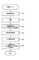
上述の順投影処理及び第2の再構成処理の具体的な例として、まず実施例(1)を図7に示す。
図7の実施例(1)では、再構成演算装置45は、上述のステップS1〜ステップS3と同様に、撮影条件の設定(ステップS11)、撮影条件に従った撮影(ステップS12)、撮影により得た投影データに基づくフィルタ補正3D逆投影処理(ステップS13)、ステップS13によって得た初期画像に基づく逐次近似処理(ステップS14)を行う。
As a specific example of the above-described forward projection process and the second reconstruction process, an example (1) is first shown in FIG.
In the embodiment (1) of FIG. 7, the
次に再構成演算装置45は、ステップS14により得た第1画像67,77に対して、2D順投影処理を行う。2D順投影処理とは、シングルスライス(単列検出器)かつノーマルスキャンによる順投影である(ステップS15)。
Next, the
この場合は、第2の再構成処理においてフィルタ補正2D逆投影処理を使用できる(ステップS16)。フィルタ補正2D逆投影処理を採用することにより、順投影データ68,78と再構成画像(最終画像69,79)とに矛盾が生じない正確な解が得られる。また、フィルタ補正2D逆投影処理の再構成フィルタとして、所望の周波数特性を有するものを適用したり、所望のFOVで再構成したりするようにすれば、ステップS14で生成した第1画像67,77とは異なる、診断に有効な最終画像69,79を生成できる。
In this case, the filter correction 2D back projection process can be used in the second reconstruction process (step S16). By adopting the filter correction 2D backprojection process, an accurate solution can be obtained in which there is no contradiction between the
例えば、撮影部位が頭部である場合には、被検体サイズが小さく、また小さな病変を識別したいため、より高周波成分を強調した再構成フィルタを使用して分解能の高い画像を生成すればよい。また、撮影部位が腹部である場合には、被写体サイズが大きいため、ノイズを低減する目的で高周波成分を抑制したフィルタを使用すればよい。
従って、実施例(1)によれば、逐次近似処理によって画質を向上させた第1画像67,77の順投影データ68,78に対して正確で、かつ診断に有効な特性を持つ解(最終画像69,79)を得ることが可能となる。
For example, when the imaging region is the head, since it is desired to identify a small lesion and a small lesion, an image with high resolution may be generated using a reconstruction filter that emphasizes higher frequency components. Further, when the imaging region is the abdomen, the subject size is large, so a filter that suppresses high frequency components may be used for the purpose of reducing noise.
Therefore, according to the embodiment (1), an accurate solution for the
また、上述の順投影処理及び第2の再構成処理の実施例(2)を図8に示す。
図8の実施例(2)では、再構成演算装置45は、上述のステップS1〜ステップS3と同様に、撮影条件の設定(ステップS21)、撮影条件に従った撮影(ステップS22)、撮影により得た投影データに基づくフィルタ補正3D逆投影処理(ステップS23)、ステップS23によって得た初期画像に基づく逐次近似処理(ステップS24)を行う。
FIG. 8 shows an embodiment (2) of the forward projection process and the second reconstruction process described above.
In the embodiment (2) of FIG. 8, the
次に再構成演算装置45は、ステップS24により得た第1画像67,77に対して、3D順投影処理を行う。3D順投影処理とは、複数列スライス(多列検出器)かつらせんスキャンによる順投影である(ステップS25)。この実施例(2)では、例えば、列数を4列程度、らせんピッチを5程度とする。
Next, the
この場合は、第2の再構成処理においてらせん補正フィルタ補正2D再構成処理を使用できる(ステップS26)。
実施例(1)の場合と比較して、順投影処理時の検出器の列数が複数であるため、コーン角が生じてしまい近似的な解となるが、第1画像67,77より画質がよく、所望の再構成条件を適用した最終画像69,79を取得できる。また、再構成処理が2次元であるため、演算時間は実施例(1)と同程度に高速に行える。特に、再構成ピッチ(スライス厚;画像平面の体軸方向の間隔)を狭くする場合には、実施例(1)よりも高速な演算を行える。また、実施例(1)と同様に、ステップS26の2D再構成処理時に所望の再構成条件(周波数特性等)を設定したりできるため、ステップS24で生成した第1画像67,77とは異なる、診断に有効な最終画像69,79を生成できる。
In this case, the spiral correction filter correction 2D reconstruction process can be used in the second reconstruction process (step S26).
Compared to the case of the embodiment (1), since there are a plurality of detector columns in the forward projection process, a cone angle is generated and an approximate solution is obtained. The
また、上述の順投影処理及び第2の再構成処理の実施例(3)を図9に示す。
図9の実施例(3)では、再構成演算装置45は、上述のステップS1〜ステップS3と同様に、撮影条件の設定(ステップS31)、撮影条件に従った撮影(ステップS32)、撮影により得た投影データに基づくフィルタ補正3D逆投影処理(ステップS33)、ステップS33によって得た初期画像に基づく逐次近似処理(ステップS34)を行う。
FIG. 9 shows an embodiment (3) of the above-described forward projection process and the second reconstruction process.
In the embodiment (3) of FIG. 9, the
次に再構成演算装置45は、ステップS34により得た第1画像67,77に対して、3D順投影処理を行う。この実施例(3)では、例えば、列数を16列程度、らせんピッチは20程度とする。
Next, the
この場合は、後述する第2の再構成処理において、Weighted Feldkamp法をベースとした重み付きフィルタ補正3D再構成処理を使用できる(ステップS36)。
第2の再構成処理を3次元とすることで、演算時間は実施例(1)及び(2)よりも低速となるが、1画像を生成するために参照するデータ数が多くなるため、実施例(2)により得られる最終画像69,79より良好な画質となる。また、実施例(1)、(2)と同様に、ステップS36の3D再構成処理時に所望の撮影条件(周波数特性等)にて再構成できるため、ステップS34で生成した第1画像67,77とは異なる、診断に有効な画像を生成できる。
In this case, a weighted filter correction 3D reconstruction process based on the weighted Feldkamp method can be used in a second reconstruction process described later (step S36).
By making the second reconstruction processing three-dimensional, the calculation time is slower than in the embodiments (1) and (2), but the number of data to be referred to generate one image is increased. The image quality is better than the
なお、本実施の形態の手順での再構成処理は、撮影した全ての画像に対して適用せずともよく、より詳細に診察したい部位を含む画像や、フィルミング(露光記録)される画像に対してのみ適用するようにしてもよい。この場合は、詳細に診察したい部位を含む画像等については画質向上を優先し、他の画像については演算処理速度を優先する等、診断を行う医師等にとって効率の良い画像生成を行える。 Note that the reconstruction process in the procedure of the present embodiment does not have to be applied to all captured images, and is applied to an image including a part to be examined in more detail or an image to be filmed (exposure recorded). You may make it apply only to. In this case, it is possible to efficiently generate an image for a doctor or the like who makes a diagnosis, such as giving priority to image quality improvement for an image including a part to be examined in detail, and giving priority to calculation processing speed for other images.
以上説明したように、本発明のX線CT装置1は、多列検出器及び所定のスキャン軌跡を用いた撮影により取得された投影データを使用して逐次近似処理を含む第1の再構成処理によって第1画像67,77を生成する。その後、生成した第1画像67,77に対して、撮影と比較してアーチファクトの混入の少ないスキャン軌跡にて順投影を行う。そして、その順投影データ68,78に基づいて、例えば所望の周波数条件等の撮影条件を設定して、解析的手法による第2の再構成処理を行って、最終画像69,79を生成する。
As described above, the
従って、多列・高速スキャンでの撮影により得た投影データに対する逐次近似処理の適用(第1の再構成処理)により、患者に負担の少ない撮影を行いつつ、ノイズやコーンビームアーチファクトを低減した良好な画像を生成できる。このような高画質な画像を基に診断に有効な画像を再び再構成するために、撮影時よりもアーチファクトの混入の少ないスキャン軌跡で順投影処理を行うことにより画質劣化を抑え、得られた順投影データに対して所望の再構成条件を適用して解析的手法による第2の再構成処理を施す。そのため、所望の特徴(周波数特性、再構成FOV等)を表現した診断に有効な画像を良好な画質で生成できる。 Therefore, by applying successive approximation processing (first reconstruction processing) to projection data obtained by imaging with multi-row and high-speed scanning, it is possible to reduce noise and cone beam artifacts while performing imaging with less burden on the patient. A simple image. In order to reconstruct an image effective for diagnosis based on such a high-quality image, the forward projection process was performed with a scan trajectory with less artifact mixing than that at the time of shooting, and image quality deterioration was suppressed and obtained. A desired reconstruction condition is applied to the forward projection data to perform a second reconstruction process by an analytical method. Therefore, an image effective for diagnosis expressing desired characteristics (frequency characteristics, reconstructed FOV, etc.) can be generated with good image quality.
特に、順投影処理時のスキャンに、2次元順投影処理(単列検出器を用いたノーマルスキャン)を採用する場合には、完全なアルゴリズムであるフィルタ補正2D逆投影法を用いて、正確かつ高速に所望の特性を有する最終画像を得ることが可能となる。 In particular, when a two-dimensional forward projection process (normal scan using a single-row detector) is adopted for the scan during the forward projection process, the filter-corrected 2D backprojection method, which is a complete algorithm, is used to accurately and accurately It becomes possible to obtain a final image having desired characteristics at high speed.
また、順投影処理時のスキャンに、撮影時よりも列数の少ない多列検出器を用い、撮影時よりも低速のらせんスキャン(3次元順投影処理)を採用する場合には、列幅やらせんピッチに応じて適したフィルタ補正再構成処理を用いた再構成処理を行うことが可能となる。例えば、フィルタ補正2D再構成処理を行えば、高速に演算を行うことが可能となり、フィルタ補正3D再構成処理を行えば、画質を向上できる。 In addition, when a multi-row detector having a smaller number of columns than that at the time of photographing is used for the scan at the time of forward projection processing and a spiral scan (three-dimensional forward projection processing) that is slower than at the time of photographing is employed, It is possible to perform reconstruction processing using filter correction reconstruction processing suitable for the pitch. For example, if the filter correction 2D reconstruction process is performed, it is possible to perform calculations at high speed, and if the filter correction 3D reconstruction process is performed, the image quality can be improved.
なお、上述の実施の形態では、順投影処理のスキャン軌跡の態様として、ノーマルスキャンやらせんスキャンとしたが、これに限定されず、ノーマルスキャンとラインスキャンの組み合わせ等、複数態様のスキャンの組み合わせとしてもよい。いずれのスキャンまたはその組み合わせであっても、コーン角が小さく、再構成画像に関連するデータ数が多くなるような順投影を行う。
また第2の再構成処理は、フィルタ補正逆投影法に限定されず、フーリエ再構成法等のフィルタ重畳型再構成法を用いてもよい。
In the above-described embodiment, the scan trajectory of the forward projection process is a normal scan or a spiral scan. However, the scan trajectory is not limited to this, and a combination of a plurality of scans such as a combination of a normal scan and a line scan. Also good. In any scan or combination thereof, forward projection is performed such that the cone angle is small and the number of data related to the reconstructed image is large.
The second reconstruction process is not limited to the filter-corrected back projection method, and a filter superposition type reconstruction method such as a Fourier reconstruction method may be used.
以上、本発明に係る再構成演算装置、再構成演算方法、及びX線CT装置の好適な実施形態について説明したが、本発明は、上述の実施形態に限定されるものではない。例えば、上述の実施の形態では、ガントリータイプのX線CT装置について説明したがCアーム型のX線CT装置でもよい。また、当業者であれば、本願で開示した技術的思想の範疇内において、各種の変更例または修正例に想到し得ることは明らかであり、それらについても当然に本発明の技術的範囲に属するものと了解される。 The preferred embodiments of the reconstruction calculation device, the reconstruction calculation method, and the X-ray CT apparatus according to the present invention have been described above, but the present invention is not limited to the above-described embodiments. For example, in the above-described embodiment, the gantry type X-ray CT apparatus has been described, but a C-arm type X-ray CT apparatus may be used. In addition, it is obvious for those skilled in the art that various changes or modifications can be conceived within the scope of the technical idea disclosed in the present application, and these naturally belong to the technical scope of the present invention. It is understood.
1・・・・・X線CT装置
2・・・・・スキャナ
21・・・中央制御装置
201・・・X線発生装置(X線源)
205・・・X線検出器
3・・・・・寝台
4・・・・・操作ユニット
41・・・・表示装置
42・・・・操作装置
43・・・・記憶装置
44・・・・演算装置
45・・・・再構成演算装置
46・・・・画像処理装置
6・・・・・被検体
205A・・・単列検出器
205B・・・多列検出器
DESCRIPTION OF
205 ... X-ray detector 3 ... bed 4 ... operating unit 41 ... display device 42 ... operating device 43 ...
Claims (7)
前記第1画像を順投影することにより順投影データを生成する順投影データ生成手段と、
前記順投影データに対して、所望の再構成条件を設定した解析的な再構成処理を行い、最終画像を再構成する第2の再構成手段と、を備え、
前記順投影データ生成手段は、
前記撮影と比較して、前記第2の再構成手段の再構成処理におけるアーチファクトの混入が少ないスキャン軌跡で、前記第1画像を順投影することを特徴とする再構成演算装置。 First reconstruction means for performing reconstruction processing including successive approximation processing on X-ray projection data acquired by imaging with a predetermined scan locus to generate a first image;
Forward projection data generation means for generating forward projection data by forward projecting the first image;
A second reconstruction unit configured to perform an analytical reconstruction process in which a desired reconstruction condition is set on the forward projection data and reconstruct a final image;
The forward projection data generation means includes:
A reconstruction calculation device that projects the first image in a forward direction with a scan trajectory in which artifacts in the reconstruction processing of the second reconstruction unit are less mixed than in the imaging.
前記第2の再構成手段は、前記2次元順投影処理により取得した順投影データに対して、所望の再構成条件にてフィルタ補正2次元逆投影処理を適用することを特徴とする請求項1に記載の再構成演算装置。 The forward projection data generation means performs a two-dimensional forward projection process on the first image by a single row detector and a normal scan,
2. The second reconstructing means applies a filter-corrected two-dimensional backprojection process under a desired reconstruction condition to the forward projection data acquired by the two-dimensional forward projection process. The reconstruction calculation device described in 1.
前記第2の再構成手段は、前記3次元順投影処理により取得した順投影データに対して、所望の再構成条件にてフィルタ補正2次元逆投影処理を適用することを特徴とする請求項1に記載の再構成演算装置。 The forward projection data generation means performs a three-dimensional forward projection process on the first image by a multi-row detector having a smaller number of rows than that at the time of shooting and a low-speed spiral scan,
2. The second reconstruction unit applies a filter-corrected two-dimensional backprojection process under a desired reconstruction condition to the forward projection data acquired by the three-dimensional forward projection process. The reconstruction calculation device described in 1.
前記第2の再構成手段は、前記3次元順投影処理により取得した順投影データに対して、所望の再構成条件にてフィルタ補正3次元逆投影処理を適用することを特徴とする請求項1に記載の再構成演算装置。 The forward projection data generating means performs a three-dimensional forward projection process on the first image by a multi-row detector having a smaller number of rows than that at the time of photographing and a low-speed spiral scan,
2. The second reconstructing means applies a filter-corrected three-dimensional backprojection process under a desired reconstruction condition to the forward projection data acquired by the three-dimensional forward projection process. The reconstruction calculation device described in 1.
前記第1画像を順投影することにより順投影データを生成する順投影データ生成ステップと、
前記順投影データに対して、所望の再構成条件を設定した解析的な再構成処理を行い、最終画像を再構成する第2の再構成ステップと、を含み、
前記順投影データ生成ステップにおいて、
前記撮影と比較して、前記第2の再構成手段の再構成処理におけるアーチファクトの混入が少ないスキャン軌跡で、前記第1画像を順投影することを特徴とする再構成演算方法。 A first reconstruction step of performing a reconstruction process including a successive approximation process on the X-ray projection data acquired by imaging with a predetermined scan locus to generate a first image;
A forward projection data generation step of generating forward projection data by forward projecting the first image;
A second reconstruction step of performing an analytical reconstruction process in which a desired reconstruction condition is set on the forward projection data, and reconstructing a final image,
In the forward projection data generation step,
A reconstruction calculation method characterized by forwardly projecting the first image with a scan trajectory with less artifacts in the reconstruction processing of the second reconstruction means compared to the imaging.
前記再構成演算装置は、
所定のスキャン軌跡による撮影にて取得した前記X線投影データに対して逐次近似処理を含む再構成処理を行い、第1画像を生成する第1の再構成手段と、
前記第1画像を順投影することにより順投影データを生成する順投影データ生成手段と、
前記順投影データに対して、所望の再構成条件を設定した解析的な再構成処理を行い、最終画像を再構成する第2の再構成手段と、を備え、
前記順投影データ生成手段は、
前記撮影と比較して、前記第2の再構成手段の再構成処理におけるアーチファクトの混入が少ないスキャン軌跡で、前記第1画像を順投影することを特徴とするX線CT装置。 A X-ray CT image based on X-ray projection data collected by a scanner that irradiates a subject with X-rays from a plurality of angular directions around the subject and collects X-ray projection data transmitted through the subject An X-ray CT apparatus comprising a reconstruction calculation device for reconfiguring
The reconstruction arithmetic device is
A first reconstruction means for performing a reconstruction process including a successive approximation process on the X-ray projection data acquired by imaging with a predetermined scan locus, and generating a first image;
Forward projection data generation means for generating forward projection data by forward projecting the first image;
A second reconstruction unit configured to perform an analytical reconstruction process in which a desired reconstruction condition is set on the forward projection data and reconstruct a final image;
The forward projection data generation means includes:
An X-ray CT apparatus for forwardly projecting the first image with a scan trajectory with less artifacts in the reconstruction processing of the second reconstruction means compared to the imaging.
Priority Applications (1)
| Application Number | Priority Date | Filing Date | Title |
|---|---|---|---|
| JP2010015030A JP5406063B2 (en) | 2010-01-27 | 2010-01-27 | Reconstruction calculation device, reconstruction calculation method, and X-ray CT apparatus |
Applications Claiming Priority (1)
| Application Number | Priority Date | Filing Date | Title |
|---|---|---|---|
| JP2010015030A JP5406063B2 (en) | 2010-01-27 | 2010-01-27 | Reconstruction calculation device, reconstruction calculation method, and X-ray CT apparatus |
Publications (3)
| Publication Number | Publication Date |
|---|---|
| JP2011152255A JP2011152255A (en) | 2011-08-11 |
| JP2011152255A5 JP2011152255A5 (en) | 2013-02-07 |
| JP5406063B2 true JP5406063B2 (en) | 2014-02-05 |
Family
ID=44538654
Family Applications (1)
| Application Number | Title | Priority Date | Filing Date |
|---|---|---|---|
| JP2010015030A Expired - Fee Related JP5406063B2 (en) | 2010-01-27 | 2010-01-27 | Reconstruction calculation device, reconstruction calculation method, and X-ray CT apparatus |
Country Status (1)
| Country | Link |
|---|---|
| JP (1) | JP5406063B2 (en) |
Families Citing this family (10)
| Publication number | Priority date | Publication date | Assignee | Title |
|---|---|---|---|---|
| JP5813994B2 (en) * | 2010-06-03 | 2015-11-17 | 株式会社東芝 | Medical image diagnostic apparatus and image reconstruction method |
| US8731269B2 (en) * | 2011-10-19 | 2014-05-20 | Kabushiki Kaisha Toshiba | Method and system for substantially reducing artifacts in circular cone beam computer tomography (CT) |
| CN104902818B (en) * | 2013-02-05 | 2017-09-29 | 株式会社日立制作所 | X ray CT device and image reconstructing method |
| CN105556507B (en) * | 2013-09-18 | 2020-05-19 | 美国西门子医疗解决公司 | Method and system for generating a reconstructed image of a target object from an input signal |
| US10119923B2 (en) * | 2015-10-19 | 2018-11-06 | L3 Security & Detection Systems, Inc. | Systems and methods for image reconstruction at high computed tomography pitch |
| US10702221B2 (en) | 2015-12-25 | 2020-07-07 | Shanghai United Imaging Healthcare Co., Ltd. | Methods and systems for CT balance measurement and adjustment |
| CN106923852B (en) * | 2015-12-30 | 2022-02-08 | 上海联影医疗科技股份有限公司 | CT device and light path abnormity detection method thereof |
| JP7046543B2 (en) * | 2017-09-27 | 2022-04-04 | 浜松ホトニクス株式会社 | Tomographic imaging device and tomographic imaging method |
| CN109765103A (en) * | 2019-03-13 | 2019-05-17 | 长安大学 | A kind of asphalt particle marker and method for tracing |
| CN111242947B (en) * | 2020-03-12 | 2024-02-20 | 南京安科医疗科技有限公司 | CT scanning image quality evaluation method, computer readable storage medium and CT scanning device |
Family Cites Families (6)
| Publication number | Priority date | Publication date | Assignee | Title |
|---|---|---|---|---|
| JPS58206726A (en) * | 1982-05-28 | 1983-12-02 | 株式会社日立製作所 | Image treating apparatus |
| JP3223195B2 (en) * | 1992-01-23 | 2001-10-29 | 株式会社日立メディコ | X-ray CT system |
| JP3556292B2 (en) * | 1994-10-28 | 2004-08-18 | 株式会社東芝 | Image processing device |
| US6351548B1 (en) * | 1999-06-23 | 2002-02-26 | The Board Of Trustees Of The University Of Illinois | Fast hierarchical reprojection algorithm for tomography |
| JP3707347B2 (en) * | 2000-04-07 | 2005-10-19 | 株式会社島津製作所 | Image processing method for X-ray CT apparatus, X-ray CT apparatus, and recording medium for X-ray CT imaging |
| JP4535795B2 (en) * | 2004-07-12 | 2010-09-01 | ジーイー・メディカル・システムズ・グローバル・テクノロジー・カンパニー・エルエルシー | Image processing apparatus and X-ray CT system |
-
2010
- 2010-01-27 JP JP2010015030A patent/JP5406063B2/en not_active Expired - Fee Related
Also Published As
| Publication number | Publication date |
|---|---|
| JP2011152255A (en) | 2011-08-11 |
Similar Documents
| Publication | Publication Date | Title |
|---|---|---|
| JP5406063B2 (en) | Reconstruction calculation device, reconstruction calculation method, and X-ray CT apparatus | |
| JP5960048B2 (en) | Reconstruction calculation device, reconstruction calculation method, and X-ray CT apparatus | |
| JP5280450B2 (en) | X-ray CT image forming method and X-ray CT apparatus using the same | |
| JP5274812B2 (en) | X-ray CT apparatus and image processing apparatus | |
| JP5142664B2 (en) | X-ray computed tomography system | |
| JP5670050B2 (en) | Image reconstruction apparatus and image reconstruction method | |
| JP2007054372A (en) | X-ray ct apparatus | |
| JP6640527B2 (en) | X-ray CT system | |
| JP2007000408A (en) | X-ray ct apparatus | |
| JP2008006032A (en) | X-ray ct scanner and x-ray ct scanning method | |
| JP4785441B2 (en) | X-ray CT system | |
| JP2015006328A (en) | Medical image diagnosis apparatus and control method | |
| JP5606667B2 (en) | X-ray CT system | |
| JP2008012206A (en) | X-ray tomographic apparatus | |
| JP5097355B2 (en) | Radiation tomography equipment | |
| JP2009089810A (en) | X-ray ct system | |
| WO2016132880A1 (en) | Arithmetic device, x-ray ct device, and image reconstruction method | |
| JP2007175154A (en) | X-ray ct apparatus | |
| JP2006187453A (en) | X-ray ct apparatus | |
| JP2008125909A (en) | X-ray ct apparatus | |
| JP2003225230A (en) | Computer tomographing apparatus | |
| JP2002204796A (en) | Three-dimensional x-ray ct equipment | |
| US20230363724A1 (en) | X-ray ct apparatus and high-quality image generation device | |
| US11055825B2 (en) | Medical image processing device and X-ray CT device provided with same, and medical image processing method | |
| JP5342682B2 (en) | X-ray computed tomography system |
Legal Events
| Date | Code | Title | Description |
|---|---|---|---|
| A521 | Request for written amendment filed |
Free format text: JAPANESE INTERMEDIATE CODE: A523 Effective date: 20121214 |
|
| A621 | Written request for application examination |
Free format text: JAPANESE INTERMEDIATE CODE: A621 Effective date: 20121214 |
|
| A977 | Report on retrieval |
Free format text: JAPANESE INTERMEDIATE CODE: A971007 Effective date: 20131015 |
|
| A01 | Written decision to grant a patent or to grant a registration (utility model) |
Free format text: JAPANESE INTERMEDIATE CODE: A01 Effective date: 20131022 |
|
| A61 | First payment of annual fees (during grant procedure) |
Free format text: JAPANESE INTERMEDIATE CODE: A61 Effective date: 20131031 |
|
| S111 | Request for change of ownership or part of ownership |
Free format text: JAPANESE INTERMEDIATE CODE: R313111 |
|
| S533 | Written request for registration of change of name |
Free format text: JAPANESE INTERMEDIATE CODE: R313533 |
|
| R350 | Written notification of registration of transfer |
Free format text: JAPANESE INTERMEDIATE CODE: R350 |
|
| LAPS | Cancellation because of no payment of annual fees |