JP5403044B2 - Projection device and projection control device - Google Patents
Projection device and projection control device Download PDFInfo
- Publication number
- JP5403044B2 JP5403044B2 JP2011277134A JP2011277134A JP5403044B2 JP 5403044 B2 JP5403044 B2 JP 5403044B2 JP 2011277134 A JP2011277134 A JP 2011277134A JP 2011277134 A JP2011277134 A JP 2011277134A JP 5403044 B2 JP5403044 B2 JP 5403044B2
- Authority
- JP
- Japan
- Prior art keywords
- light
- coherent light
- optical system
- recording medium
- hologram recording
- Prior art date
- Legal status (The legal status is an assumption and is not a legal conclusion. Google has not performed a legal analysis and makes no representation as to the accuracy of the status listed.)
- Active
Links
- 230000003287 optical effect Effects 0.000 claims description 258
- 230000001427 coherent effect Effects 0.000 claims description 171
- 238000009792 diffusion process Methods 0.000 claims description 43
- 239000004973 liquid crystal related substance Substances 0.000 claims description 14
- 238000005286 illumination Methods 0.000 description 40
- 238000000034 method Methods 0.000 description 32
- 239000000463 material Substances 0.000 description 24
- 230000008569 process Effects 0.000 description 12
- 238000013461 design Methods 0.000 description 8
- 238000010586 diagram Methods 0.000 description 8
- 230000005540 biological transmission Effects 0.000 description 7
- 230000000694 effects Effects 0.000 description 6
- 230000008859 change Effects 0.000 description 5
- 230000004048 modification Effects 0.000 description 5
- 238000012986 modification Methods 0.000 description 5
- 239000003086 colorant Substances 0.000 description 4
- 239000011521 glass Substances 0.000 description 4
- 230000001678 irradiating effect Effects 0.000 description 4
- QSHDDOUJBYECFT-UHFFFAOYSA-N mercury Chemical compound [Hg] QSHDDOUJBYECFT-UHFFFAOYSA-N 0.000 description 4
- 229910052753 mercury Inorganic materials 0.000 description 4
- 239000011022 opal Substances 0.000 description 3
- GGCZERPQGJTIQP-UHFFFAOYSA-N sodium;9,10-dioxoanthracene-2-sulfonic acid Chemical compound [Na+].C1=CC=C2C(=O)C3=CC(S(=O)(=O)O)=CC=C3C(=O)C2=C1 GGCZERPQGJTIQP-UHFFFAOYSA-N 0.000 description 3
- 239000002245 particle Substances 0.000 description 2
- 230000009467 reduction Effects 0.000 description 2
- 229910052710 silicon Inorganic materials 0.000 description 2
- 239000010703 silicon Substances 0.000 description 2
- 241000282412 Homo Species 0.000 description 1
- 206010034972 Photosensitivity reaction Diseases 0.000 description 1
- 230000002159 abnormal effect Effects 0.000 description 1
- 230000009471 action Effects 0.000 description 1
- 238000007792 addition Methods 0.000 description 1
- 230000002411 adverse Effects 0.000 description 1
- 238000013459 approach Methods 0.000 description 1
- 238000003491 array Methods 0.000 description 1
- 239000002131 composite material Substances 0.000 description 1
- 238000012217 deletion Methods 0.000 description 1
- 230000037430 deletion Effects 0.000 description 1
- 238000005516 engineering process Methods 0.000 description 1
- 230000004907 flux Effects 0.000 description 1
- 229910052738 indium Inorganic materials 0.000 description 1
- 230000007246 mechanism Effects 0.000 description 1
- 230000002093 peripheral effect Effects 0.000 description 1
- 230000036211 photosensitivity Effects 0.000 description 1
- 230000010287 polarization Effects 0.000 description 1
- 238000012805 post-processing Methods 0.000 description 1
- 239000011347 resin Substances 0.000 description 1
- 229920005989 resin Polymers 0.000 description 1
- 239000004065 semiconductor Substances 0.000 description 1
- 238000007493 shaping process Methods 0.000 description 1
- 238000001228 spectrum Methods 0.000 description 1
- 238000012360 testing method Methods 0.000 description 1
Images


Classifications
-
- G—PHYSICS
- G03—PHOTOGRAPHY; CINEMATOGRAPHY; ANALOGOUS TECHNIQUES USING WAVES OTHER THAN OPTICAL WAVES; ELECTROGRAPHY; HOLOGRAPHY
- G03B—APPARATUS OR ARRANGEMENTS FOR TAKING PHOTOGRAPHS OR FOR PROJECTING OR VIEWING THEM; APPARATUS OR ARRANGEMENTS EMPLOYING ANALOGOUS TECHNIQUES USING WAVES OTHER THAN OPTICAL WAVES; ACCESSORIES THEREFOR
- G03B21/00—Projectors or projection-type viewers; Accessories therefor
- G03B21/14—Details
- G03B21/20—Lamp housings
- G03B21/2066—Reflectors in illumination beam
-
- G—PHYSICS
- G02—OPTICS
- G02B—OPTICAL ELEMENTS, SYSTEMS OR APPARATUS
- G02B26/00—Optical devices or arrangements for the control of light using movable or deformable optical elements
- G02B26/08—Optical devices or arrangements for the control of light using movable or deformable optical elements for controlling the direction of light
- G02B26/10—Scanning systems
- G02B26/105—Scanning systems with one or more pivoting mirrors or galvano-mirrors
-
- G—PHYSICS
- G02—OPTICS
- G02B—OPTICAL ELEMENTS, SYSTEMS OR APPARATUS
- G02B27/00—Optical systems or apparatus not provided for by any of the groups G02B1/00 - G02B26/00, G02B30/00
- G02B27/48—Laser speckle optics
-
- G—PHYSICS
- G02—OPTICS
- G02B—OPTICAL ELEMENTS, SYSTEMS OR APPARATUS
- G02B5/00—Optical elements other than lenses
- G02B5/32—Holograms used as optical elements
-
- G—PHYSICS
- G03—PHOTOGRAPHY; CINEMATOGRAPHY; ANALOGOUS TECHNIQUES USING WAVES OTHER THAN OPTICAL WAVES; ELECTROGRAPHY; HOLOGRAPHY
- G03B—APPARATUS OR ARRANGEMENTS FOR TAKING PHOTOGRAPHS OR FOR PROJECTING OR VIEWING THEM; APPARATUS OR ARRANGEMENTS EMPLOYING ANALOGOUS TECHNIQUES USING WAVES OTHER THAN OPTICAL WAVES; ACCESSORIES THEREFOR
- G03B21/00—Projectors or projection-type viewers; Accessories therefor
- G03B21/14—Details
- G03B21/142—Adjusting of projection optics
-
- G—PHYSICS
- G03—PHOTOGRAPHY; CINEMATOGRAPHY; ANALOGOUS TECHNIQUES USING WAVES OTHER THAN OPTICAL WAVES; ELECTROGRAPHY; HOLOGRAPHY
- G03B—APPARATUS OR ARRANGEMENTS FOR TAKING PHOTOGRAPHS OR FOR PROJECTING OR VIEWING THEM; APPARATUS OR ARRANGEMENTS EMPLOYING ANALOGOUS TECHNIQUES USING WAVES OTHER THAN OPTICAL WAVES; ACCESSORIES THEREFOR
- G03B21/00—Projectors or projection-type viewers; Accessories therefor
- G03B21/14—Details
- G03B21/20—Lamp housings
- G03B21/2006—Lamp housings characterised by the light source
- G03B21/2033—LED or laser light sources
-
- G—PHYSICS
- G03—PHOTOGRAPHY; CINEMATOGRAPHY; ANALOGOUS TECHNIQUES USING WAVES OTHER THAN OPTICAL WAVES; ELECTROGRAPHY; HOLOGRAPHY
- G03B—APPARATUS OR ARRANGEMENTS FOR TAKING PHOTOGRAPHS OR FOR PROJECTING OR VIEWING THEM; APPARATUS OR ARRANGEMENTS EMPLOYING ANALOGOUS TECHNIQUES USING WAVES OTHER THAN OPTICAL WAVES; ACCESSORIES THEREFOR
- G03B21/00—Projectors or projection-type viewers; Accessories therefor
- G03B21/14—Details
- G03B21/20—Lamp housings
- G03B21/208—Homogenising, shaping of the illumination light
-
- G—PHYSICS
- G03—PHOTOGRAPHY; CINEMATOGRAPHY; ANALOGOUS TECHNIQUES USING WAVES OTHER THAN OPTICAL WAVES; ELECTROGRAPHY; HOLOGRAPHY
- G03H—HOLOGRAPHIC PROCESSES OR APPARATUS
- G03H1/00—Holographic processes or apparatus using light, infrared or ultraviolet waves for obtaining holograms or for obtaining an image from them; Details peculiar thereto
- G03H1/04—Processes or apparatus for producing holograms
- G03H1/0402—Recording geometries or arrangements
-
- G—PHYSICS
- G03—PHOTOGRAPHY; CINEMATOGRAPHY; ANALOGOUS TECHNIQUES USING WAVES OTHER THAN OPTICAL WAVES; ELECTROGRAPHY; HOLOGRAPHY
- G03H—HOLOGRAPHIC PROCESSES OR APPARATUS
- G03H1/00—Holographic processes or apparatus using light, infrared or ultraviolet waves for obtaining holograms or for obtaining an image from them; Details peculiar thereto
- G03H1/22—Processes or apparatus for obtaining an optical image from holograms
- G03H1/2286—Particular reconstruction light ; Beam properties
-
- G—PHYSICS
- G03—PHOTOGRAPHY; CINEMATOGRAPHY; ANALOGOUS TECHNIQUES USING WAVES OTHER THAN OPTICAL WAVES; ELECTROGRAPHY; HOLOGRAPHY
- G03H—HOLOGRAPHIC PROCESSES OR APPARATUS
- G03H1/00—Holographic processes or apparatus using light, infrared or ultraviolet waves for obtaining holograms or for obtaining an image from them; Details peculiar thereto
- G03H1/22—Processes or apparatus for obtaining an optical image from holograms
- G03H1/2294—Addressing the hologram to an active spatial light modulator
-
- G—PHYSICS
- G03—PHOTOGRAPHY; CINEMATOGRAPHY; ANALOGOUS TECHNIQUES USING WAVES OTHER THAN OPTICAL WAVES; ELECTROGRAPHY; HOLOGRAPHY
- G03H—HOLOGRAPHIC PROCESSES OR APPARATUS
- G03H1/00—Holographic processes or apparatus using light, infrared or ultraviolet waves for obtaining holograms or for obtaining an image from them; Details peculiar thereto
- G03H1/32—Systems for obtaining speckle elimination
-
- H—ELECTRICITY
- H04—ELECTRIC COMMUNICATION TECHNIQUE
- H04N—PICTORIAL COMMUNICATION, e.g. TELEVISION
- H04N9/00—Details of colour television systems
- H04N9/12—Picture reproducers
- H04N9/31—Projection devices for colour picture display, e.g. using electronic spatial light modulators [ESLM]
- H04N9/3129—Projection devices for colour picture display, e.g. using electronic spatial light modulators [ESLM] scanning a light beam on the display screen
-
- G—PHYSICS
- G03—PHOTOGRAPHY; CINEMATOGRAPHY; ANALOGOUS TECHNIQUES USING WAVES OTHER THAN OPTICAL WAVES; ELECTROGRAPHY; HOLOGRAPHY
- G03H—HOLOGRAPHIC PROCESSES OR APPARATUS
- G03H1/00—Holographic processes or apparatus using light, infrared or ultraviolet waves for obtaining holograms or for obtaining an image from them; Details peculiar thereto
- G03H1/04—Processes or apparatus for producing holograms
- G03H1/0402—Recording geometries or arrangements
- G03H2001/0439—Recording geometries or arrangements for recording Holographic Optical Element [HOE]
-
- G—PHYSICS
- G03—PHOTOGRAPHY; CINEMATOGRAPHY; ANALOGOUS TECHNIQUES USING WAVES OTHER THAN OPTICAL WAVES; ELECTROGRAPHY; HOLOGRAPHY
- G03H—HOLOGRAPHIC PROCESSES OR APPARATUS
- G03H1/00—Holographic processes or apparatus using light, infrared or ultraviolet waves for obtaining holograms or for obtaining an image from them; Details peculiar thereto
- G03H1/22—Processes or apparatus for obtaining an optical image from holograms
- G03H1/2286—Particular reconstruction light ; Beam properties
- G03H2001/2292—Using scanning means
Description
本発明は、コヒーレント光を照射する光源を用いた投射装置および投射制御装置に関する。 The present invention relates to a projection apparatus and a projection control apparatus using a light source that emits coherent light.
スクリーン上に映像光を投射する投射装置が広く使用されている。典型的な投射装置では、液晶マイクロディスプレイやDMD(デジタルマイクロミラーデバイス:Digital Micromirror Device)といった空間光変調器を用いて元になる二次元画像を生成し、この二次元画像を投射光学系を利用してスクリーン上に拡大投影することにより、スクリーン上に映像を表示している。 Projection devices that project image light onto a screen are widely used. A typical projection device uses a spatial light modulator such as a liquid crystal micro display or DMD (Digital Micromirror Device) to generate the original two-dimensional image, and uses this two-dimensional image using a projection optical system. The image is displayed on the screen by enlarging and projecting it on the screen.
投射装置としては、いわゆる「光学式プロジェクタ」と呼ばれている市販品を含めて、様々な方式のものが提案されている。一般的な光学式プロジェクタでは、高圧水銀ランプなどの白色光源からなる照明装置を用いて液晶ディスプレイ等の空間光変調器を照明し、得られた変調画像をレンズでスクリーン上に拡大投影する方式を採っている。たとえば、下記の特許文献1には、超高圧水銀ランプで発生させた白色光を、ダイクロイックミラーによってR,G,Bの三原色成分に分け、これらの光を各原色ごとの空間光変調器へ導き、生成された各原色ごとの変調画像をクロスダイクロイックプリズムによって合成してスクリーン上に投影する技術が開示されている。 Various types of projectors have been proposed, including commercially available products called “optical projectors”. In general optical projectors, a spatial light modulator such as a liquid crystal display is illuminated using a lighting device consisting of a white light source such as a high-pressure mercury lamp, and the resulting modulated image is projected onto a screen using a lens. Adopted. For example, in Patent Document 1 below, white light generated by an ultra-high pressure mercury lamp is divided into three primary color components of R, G, and B by a dichroic mirror, and these lights are guided to a spatial light modulator for each primary color. A technique is disclosed in which a generated modulated image for each primary color is synthesized by a cross dichroic prism and projected onto a screen.
ただし、高圧水銀ランプなどの高輝度放電ランプは、寿命が比較的短く、光学式プロジェクタなどに利用した場合、頻繁にランプ交換を行う必要がある。また、各原色成分の光を取り出すために、ダイクロイックミラーなどの比較的大型な光学系を利用する必要があるため、装置全体が大型化するという難点がある。 However, high-intensity discharge lamps such as high-pressure mercury lamps have a relatively short life, and when used in optical projectors or the like, it is necessary to frequently replace the lamps. Further, since it is necessary to use a relatively large optical system such as a dichroic mirror in order to extract the light of each primary color component, there is a problem that the entire apparatus becomes large.
このような問題に対処するため、レーザなどのコヒーレント光源を用いる方式も提案されている。たとえば、産業上で広く利用されている半導体レーザは、高圧水銀ランプなどの高輝度放電ランプに比べて極めて長寿命である。また、単一波長の光を生成可能な光源であるため、ダイクロイックミラーなどの分光装置が不要になり、装置全体を小型化できるという利点も有する。 In order to cope with such a problem, a method using a coherent light source such as a laser has been proposed. For example, a semiconductor laser widely used in the industry has a very long life compared to a high-intensity discharge lamp such as a high-pressure mercury lamp. In addition, since the light source can generate light having a single wavelength, a spectroscopic device such as a dichroic mirror is not necessary, and the entire device can be reduced in size.
例えば、下記の特許文献2には、ガルバノスキャナでレーザ光を走査させて、光拡散板に2次元画像を形成する技術が開示されている。この特許文献2に開示された光拡散板は、画角を拡げるために設けられるものであり、光拡散板に形成された2次元画像がそのままスクリーンに投射されるため、投射画像の画質は悪くなってしまう。 For example, Patent Document 2 below discloses a technique for forming a two-dimensional image on a light diffusion plate by scanning a laser beam with a galvano scanner. The light diffusing plate disclosed in Patent Document 2 is provided to widen the angle of view, and since the two-dimensional image formed on the light diffusing plate is directly projected onto the screen, the image quality of the projected image is poor. turn into.
ところで、レーザ光などのコヒーレント光源を用いる方式には、スペックルの発生といった新たな問題が生じている。スペックル(speckle)は、レーザ光などのコヒーレント光を散乱面に照射したときに現れる斑点状の模様であり、スクリーン上に発生すると斑点状の輝度ムラ(明るさのムラ)として観察され、観察者に対して生理的な悪影響を及ぼす要因になる。コヒーレント光を用いた場合にスペックルが発生する理由は、スクリーンなどの散乱反射面の各部で反射したコヒーレント光が、その極めて高い可干渉性ゆえに、互いに干渉し合うことによって生じるものとされている。たとえば、下記の非特許文献1には、スペックルの発生についての詳細な理論的考察がなされている。 By the way, the method using a coherent light source such as a laser beam has a new problem such as generation of speckle. A speckle is a speckled pattern that appears when a scattering surface is irradiated with laser light or other coherent light. When it appears on a screen, it is observed as speckled brightness irregularities (brightness irregularities). It becomes a factor having a physiological adverse effect on the person. The reason why speckles occur when coherent light is used is that coherent light reflected by each part of a scattering reflection surface such as a screen interferes with each other because of its extremely high coherence. . For example, in the following Non-Patent Document 1, detailed theoretical considerations regarding the generation of speckle are made.
このように、コヒーレント光源を用いる方式では、スペックルの発生という固有の問題が生じるため、スペックルの発生を抑制するための技術が提案されている。たとえば、下記の特許文献3には、レーザ光を散乱板に照射し、そこから得られる散乱光を空間光変調器に導くとともに、散乱板をモータによって回転駆動することにより、スペックルを低減する技術が開示されている。 As described above, in the system using the coherent light source, a problem inherent to the generation of speckles occurs, and thus a technique for suppressing the generation of speckles has been proposed. For example, in Patent Document 3 below, the speckle is reduced by irradiating a scattering plate with laser light, guiding the scattered light obtained therefrom to a spatial light modulator, and rotating the scattering plate with a motor. Technology is disclosed.
上述したとおり、コヒーレント光源を用いた投射装置において、スペックルを低減する技術が提案されているが、これまでに提案された手法では、スペックルを効率的かつ十分に抑制することはできていない。たとえば、前掲の特許文献3に開示されている方法では、レーザ光を散乱板に照射して散乱させてしまうため、一部のレーザ光は映像表示に全く貢献することなく浪費されてしまう。また、スペックル低減のために散乱板を回転させる必要があるが、そのような機械的な回転機構は比較的大型の装置となり、また、電力消費も大きくなる。更に、散乱板を回転させたとしても、照明光の光軸の位置は変わらないため、スクリーン上での拡散に起因して発生するスペックルを十分に抑制することはできない。 As described above, in a projection apparatus using a coherent light source, a technique for reducing speckle has been proposed. However, the techniques proposed so far cannot efficiently and sufficiently suppress speckle. . For example, in the method disclosed in the above-mentioned Patent Document 3, laser light is irradiated on the scattering plate and scattered, and therefore, part of the laser light is wasted without contributing to video display at all. Moreover, although it is necessary to rotate a scattering plate for speckle reduction, such a mechanical rotation mechanism becomes a comparatively large apparatus, and also power consumption becomes large. Furthermore, even if the scattering plate is rotated, the position of the optical axis of the illumination light does not change, so that speckles generated due to diffusion on the screen cannot be sufficiently suppressed.
ところで、コヒーレント光は、レーザ光に代表されるように、優れた直進性を有するとともに、非常にエネルギ密度の高い光として照射され得る。したがって、実際に開発される照明装置としては、このようなコヒーレント光の特性に対応して、コヒーレント光の光路が設計されていることが好ましい。 By the way, coherent light, as represented by laser light, can be irradiated as light having excellent straightness and extremely high energy density. Therefore, it is preferable that the light path of the coherent light is designed as an illuminating device actually developed corresponding to the characteristics of the coherent light.
本件発明者らは、以上の点を踏まえて鋭意研究を重ね、その結果として、コヒーレント光で光変調器を照明した状態で、光変調器で生成される変調画像を投射させる投射装置を発明するにいたった。また、本件発明者らは、さらに研究を進め、コヒーレント光で光変調器を照明する際に、照明領域内に明るさが突出して明るくなる領域が生じることを安定して防止し得るように、当該照明装置を改善することができた。すなわち、本発明は、スペックルを目立たなくさせることができ、且つ照明領域内の明るさのムラの発生を効果的に抑制でき、且つ照明領域内の照明強度を向上可能な投射装置および投射制御装置を提供することを目的とする。 The inventors of the present invention have made extensive studies based on the above points, and as a result, invented a projection device that projects a modulated image generated by the optical modulator while the optical modulator is illuminated with coherent light. I went to. In addition, the present inventors have further researched, and when illuminating the light modulator with coherent light, it is possible to stably prevent the occurrence of a bright area protruding in the illumination area. The lighting device could be improved. That is, the present invention makes it possible to make speckle inconspicuous, effectively suppress the occurrence of uneven brightness in the illumination area, and improve the illumination intensity in the illumination area, and projection control An object is to provide an apparatus.
上記の課題を解決するために、本発明の一態様では、コヒーレント光を拡散し得る光学素子と、
コヒーレント光が前記光学素子上を走査するように、前記光学素子に前記コヒーレント光を照射する照射装置と、
前記照射装置から前記光学素子の各位置に入射されて拡散されたコヒーレント光によって照明される光変調器と、
前記光変調器で生成される変調画像を拡散面に投射する投射光学系と、
前記光学素子と前記光変調器との間に配置され、前記光学素子で拡散されたコヒーレント光の拡散角度を抑制する中間光学系と、を備え、
前記光学素子から拡散されたコヒーレント光は、前記中間光学系にて拡散角度が抑制された後、前記光変調器を重ねて照明することを特徴とする投射装置が提供される。
また、本発明の一態様では、コヒーレント光を拡散し得る光学素子と、
前記コヒーレント光の進行方向を変化させて、該コヒーレント光を前記光学素子上で走査させる走査デバイスと、
前記光学素子で拡散されたコヒーレント光の拡散角度を抑制する中間光学系とを備え、 前記光学素子から拡散されたコヒーレント光は、前記中間光学系にて拡散角度が抑制された後、被照明領域を重ねて照明することを特徴とする投射制御装置が提供される。
In order to solve the above problems, in one embodiment of the present invention, an optical element capable of diffusing coherent light;
An irradiation device for irradiating the optical element with the coherent light so that coherent light scans the optical element;
A light modulator that is illuminated by the coherent light that is incident and diffused from the irradiation device to each position of the optical element;
A projection optical system that projects a modulated image generated by the light modulator onto a diffusion surface;
An intermediate optical system that is disposed between the optical element and the optical modulator and suppresses a diffusion angle of coherent light diffused by the optical element,
The coherent light diffused from the optical element is illuminated by overlapping the light modulator after the diffusion angle is suppressed by the intermediate optical system.
In one embodiment of the present invention, an optical element that can diffuse coherent light;
A scanning device that changes a traveling direction of the coherent light and scans the coherent light on the optical element;
An intermediate optical system that suppresses the diffusion angle of the coherent light diffused by the optical element, and the coherent light diffused from the optical element is subjected to an illumination area after the diffusion angle is suppressed by the intermediate optical system. A projection control device is provided, which illuminates with overlapping.
本発明によれば、被照明領域または映像を投射する面上でのスペックルを効果的に目立たなくさせることができるとともに、被照明領域または映像を投射する面上での明るさおよび色にムラが生じてしまうことを効果的に抑制でき、且つ被照明領域内の照明強度を向上できる。また、中間光学系を設けることで、投射光学系の光変調器側をテレセントリックにすることができ、投射光学系の設計を簡略化でき、投射光学系の小型化および部品コスト削減が図れる。 According to the present invention, speckles on an illuminated area or a surface on which an image is projected can be effectively made inconspicuous, and brightness and color on the illuminated area or the surface on which an image is projected are uneven. Can be effectively suppressed, and the illumination intensity in the illuminated area can be improved. Further, by providing the intermediate optical system, the optical modulator side of the projection optical system can be made telecentric, the design of the projection optical system can be simplified, and the projection optical system can be miniaturized and the parts cost can be reduced.
以下、図面を参照しながら、本発明の実施形態について詳細に説明する。なお、本件明細書に添付する図面においては、図示と理解のしやすさの便宜上、縮尺および縦横の寸法比等を、実物のそれらから適宜変更したり、誇張してある。 Hereinafter, embodiments of the present invention will be described in detail with reference to the drawings. In the drawings attached to the present specification, for convenience of illustration and understanding, the scale, the vertical / horizontal dimensional ratio, and the like are appropriately changed or exaggerated from those of the actual ones.
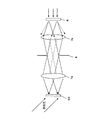
図1は一実施形態に係る投射装置20の概略構成を示すブロック図である。図1の投射装置20は、光学素子50と、照射装置60と、光変調器30と、中間光学系70と、投射光学系80とを備えている。本明細書では、光学素子50と照射装置60とを合わせたものを照明装置40と呼ぶ。
FIG. 1 is a block diagram showing a schematic configuration of a
照射装置60は、コヒーレント光が光学素子50の表面を走査するように、光学素子50にコヒーレント光を照射する。照射装置60は、コヒーレント光を放射するレーザ光源61と、レーザ光源61から放射されたコヒーレント光を光学素子50の表面上で走査させる走査デバイス65とを有する。
The
光学素子50は、光変調器30の位置に重ねて設けられる被照明領域LZに散乱板の像を再生し得るホログラム記録媒体55を有する。ホログラム記録媒体55の詳細については後述する。ホログラム記録媒体55には、走査デバイス65にて反射されたコヒーレント光が入射される。ホログラム記録媒体55には干渉縞が形成されており、コヒーレント光が入射されると、干渉縞で回折されたコヒーレント光が発散光(拡散光)となって放射される。
The
走査デバイス65は、入射されたコヒーレント光の反射角度を一定周期で可変させて、反射されたコヒーレント光がホログラム記録媒体55上を走査するようにしている。
The
ホログラム記録媒体55上の各点に入射されたコヒーレント光は、拡散光となって、中間光学系70に入射される。中間光学系70は、ホログラム記録媒体と光変調器30の間に配置されて、ホログラム記録媒体で拡散したコヒーレント光の拡散角(以下、発散角とも呼ぶ)を抑制する作用を行なう。中間光学系70は、両面が凸形状のフィールドレンズ71や、ホログラム記録媒体55側が凸形状で光変調器30側が平坦なフィールドレンズ71等で構成される。
The coherent light incident on each point on the
図2は中間光学系70の作用を説明する図である。中間光学系70は、ホログラム記録媒体55上の任意の位置に設けられる発散点を仮想的に遠ざける作用を行なう。これにより、図2の一点鎖線および実線で示すように、中間光学系70に入射されて拡散されたコヒーレント光の発散角は、中間光学系70がない場合に比べて抑制されることになる。
FIG. 2 is a diagram for explaining the operation of the intermediate
このような中間光学系70を設けることで、ホログラム記録媒体55上の任意の位置で拡散されたコヒーレント光は、中間光学系70にてその拡散角が抑制されて、光変調器30の位置に設けられる被照明領域LZに入射される。これにより、ホログラム記録媒体55で拡散されたコヒーレント光のうち、被照明領域LZの照明に用いられないコヒーレント光の割合を減らすことができ、被照明領域LZの照明強度をより向上できる。
By providing such an intermediate
また、中間光学系70を設けることで、光変調器30に入射されるコヒーレント光の主光線の方向が光変調器30の光軸の方向に近づく。後述するように、光変調器30は、反射型あるいは透過型LCOS(Liquid Crystal on Silicon)、または透過型の液晶パネル等の液晶デバイスで構成されることが多く、この種の液晶デバイスではそもそも、照明光を光軸に略平行に入射することを想定している。したがって、中間光学系70を設けると、元々想定した方向のコヒーレント光が光変調器30に入射されることになり、光変調器30から照射される変調画像光も、その光軸に略平行な方向に進行する。この場合、投射光学系80を構成するプロジェクションレンズ81に入射される変調画像光の光束の範囲を狭めることができる。これはすなわち、プロジェクションレンズ81の光変調器30側がテレセントリックになることを意味する。テレセントリックとは、主光線が光軸に平行に進行することを指す。
Further, by providing the intermediate
プロジェクションレンズ81の光変調器30側がテレセントリックの場合は、プロジェクションレンズ81のf値を高くすることができる。f値は、レンズの焦点距離をレンズの有効径で割った値であり、f値が大きいほど、レンズに入射される光束の範囲が狭くなり、暗いレンズになるが、被写体深度は大きくなり、焦点ボケを抑制できる。f値が大きいレンズは、レンズの中心付近しか被写体光が入射されないため、レンズの有効径を小さくでき、かつレンズの周辺部分について厳密にレンズ特性を規定する必要がなくなることから、レンズの設計が容易になる。すなわち、中間光学系70を設けることで、プロジェクションレンズ81の部品コストと設計コストを削減できる。
When the
このように、ホログラム記録媒体55と光変調器30の間に中間光学系70を設けるという簡易な光学系の変更を行なうだけで、プロジェクションレンズ81の光変調器30側をテレセントリックに近づけることができ、これにより、プロジェクションレンズ81のf値を大きくすることが可能となり、プロジェクションレンズ81の設計が容易となって、またプロジェクションレンズ81の部品コストも抑制できる。
In this way, the
光変調器30としては、例えば、透過型の液晶マイクロディスプレイ例えば、LCOS(Liquid Crystal on Silicon)を用いることができる。この場合、照明装置40によって面状に照明される液晶マイクロディスプレイが、画素毎にコヒーレント光を選択して透過させることにより、液晶マイクロディスプレイ上に変調画像が形成される。こうして得られた変調画像(映像光)は、投射光学系80によって、必要に応じて変倍されて拡散スクリーン15へ投射される。拡散スクリーン15に投射される変調画像のスペックルパターンは時間的に変化するため、スペックルは不可視化される。
As the
光変調器30としては、反射型のマイクロディスプレイを用いることも可能である。この場合、光変調器30での反射光によって変調画像が形成され、光変調器30へ照明装置40からコヒーレント光が照射される面と、光変調器30で生成された変調画像の映像光(反射光)の出射面が同一の面となる。このような反射光を利用する場合、光変調器30としてDMD(Digital Micromirror Device)などのMEMS(Micro Electro Mechanical Systems)素子を用いることも可能である。上述した特許文献2に開示された装置では、DMDが光変調器30として利用されている。この他、光変調器30としては、透過型の液晶パネルを用いることも可能である。
As the
また、光変調器30の入射面は、照明装置40がコヒーレント光を照射する被照明領域LZと同一の形状および大きさであることが好ましい。この場合、照明装置40からのコヒーレント光を、拡散スクリーン15への映像の表示に高い利用効率で利用することができるからである。
Moreover, it is preferable that the incident surface of the
光変調器30で生成された変調画像を拡散スクリーン15に投射する投射光学系80は、例えば両面凸形状のプロジェクションレンズ81を有し、光変調器30で生成された変調画像は、プロジェクションレンズ81で屈折されて拡散スクリーン15上に変調画像71を投射する。プロジェクションレンズ81の径や、プロジェクションレンズ81と光変調器30との距離や、プロジェクションレンズ81と拡散スクリーン15との距離によって、拡散スクリーン15に投影される変調画像71のサイズを調整することができる。図1の拡散スクリーン15は、透過型であり、投射された変調画像光を拡散する。なお、拡散スクリーン15は、反射型でもよい。
The projection
図1では省略しているが、拡散スクリーン15で拡散された変調画像を、不図示のハーフミラーに入射して、このハーフミラーで、拡散スクリーン15で拡散された変調画像光の一部を反射させて変調画像の虚像を形成して、この虚像を外光とともにハーフミラーを介して観察者が視認できるようにしてもよい。これにより、ヘッドアップディスプレイ装置を実現できる。この場合、ハーフミラーとして、例えば、車両のフロントガラスを用いることができ、観察者は運転席に座って前方を向くことで、フロントガラスを通して車外の景色を見ながら、虚像を視認できる。あるいは、ハーフミラーの代わりに、ホログラム記録媒体55やプリズムを用いてもよい。
Although omitted in FIG. 1, the modulated image diffused by the
光変調器30では、種々の変調画像を生成可能であり、光変調器30で変調画像を生成して、それを被照明領域LZで照明することで、種々の変調画像を拡散スクリーン上に投射することができる。
The
本実施形態では、被照明領域LZを照明するために、ホログラム記録媒体55を含む光学素子50を用いている。ホログラム記録媒体55は、例えばフォトポリマーを用いた反射型の体積型ホログラムである。図3はホログラム記録媒体55に散乱板の像を干渉縞として形成する様子を説明する図である。
In the present embodiment, the
図3に示すように、ホログラム記録媒体55は、実物の散乱板6からの散乱光を物体光Loとして用いて作製されている。図3には、ホログラム記録媒体55をなすようになる感光性を有したホログラム感光材料58に、互いに干渉性を有するコヒーレント光からなる参照光Lrと物体光Loとが露光されている状態が示されている。
As shown in FIG. 3, the
参照光Lrとしては、例えば、特定波長域のレーザ光を発振するレーザ光源61からのレーザ光が用いられる。参照光Lrは、レンズからなる集光素子7を透過してホログラム感光材料58に入射する。図3に示す例では、参照光Lrを形成するためのレーザ光が、集光素子7の光軸と平行な平行光束として、集光素子7へ入射する。参照光Lrは、集光素子7を透過することによって、それまでの平行光束から収束光束に整形(変換)され、ホログラム感光材料58へ入射する。この際、収束光束Lrの焦点位置FPは、ホログラム感光材料58を通り過ぎた位置にある。すなわち、ホログラム感光材料58は、集光素子7と、集光素子7によって集光された収束光束Lrの焦点位置FPと、の間に配置される。
As the reference light Lr, for example, laser light from a
一方、物体光Loは、例えばオパールガラスからなる散乱板6からの散乱光として、ホログラム感光材料58に入射する。図3の例では、作製されるべきホログラム記録媒体55が反射型であり、物体光Loは、参照光Lrと反対側の面からホログラム感光材料58へ入射する。物体光Loは、参照光Lrと干渉性を有することが前提である。したがって、例えば、同一のレーザ光源61から発振されたレーザ光を分割させて、分割された一方を上述の参照光Lrとして利用し、他方を物体光Loとして使用することができる。
On the other hand, the object light Lo is incident on the hologram
図3に示す例では、散乱板6の板面への法線方向と平行な平行光束が、散乱板6へ入射して散乱され、そして、散乱板6を透過した散乱光が物体光Loとしてホログラム感光材料58へ入射している。この方法によれば、通常安価に入手可能な等方散乱板を散乱板6として用いた場合に、散乱板6からの物体光Loを、ホログラム感光材料58に概ね均一な光量分布で入射させることができる。またこの方法によれば、散乱板6による散乱の度合いにも依存するが、ホログラム感光材料58の各位置に、散乱板6の出射面6aの全域から概ね均一な光量で物体光Loが入射しやすくなる。このような場合には、得られたホログラム記録媒体55の各位置に入射した光が、それぞれ、散乱板6の像5を同様の明るさで再生し、かつ、再生された散乱板6の像5を概ね均一な明るさで観察することが実現され得る。
In the example shown in FIG. 3, a parallel light beam parallel to the normal direction to the plate surface of the
以上のようにして、参照光Lrおよび物体光Loがホログラム記録材料58に露光されると、参照光Lrおよび物体光Loが干渉してなる干渉縞が生成され、この光の干渉縞が、何らかのパターン例えば、体積型ホログラムでは、一例として、屈折率変調パターンとして、ホログラム記録材料58に記録される。その後、ホログラム記録材料58の種類に対応した適切な後処理が施され、ホログラム記録材料55が得られる。
As described above, when the
図4は図3の露光工程を経て得られたホログラム記録媒体55に形成された干渉縞を用いて散乱板の像を再生する様子を説明する図である。図4に示すように、図3のホログラム感光材料58にて形成されたホログラム記録媒体55は、露光工程で用いられたレーザ光と同一波長の光であって、露光工程における参照光Lrの光路を逆向きに進む光によって、そのブラッグ条件が満たされるようになる。すなわち、図4に示すように、露光工程時におけるホログラム感光材料58に対する焦点FPの相対位置(図3参照)と同一の位置関係をなすようにしてホログラム記録媒体55に対して位置する基準点SPから発散し、露光工程時における参照光Lrと同一の波長を有する発散光束は、再生照明光Laとして、ホログラム記録媒体55にて回折され、露光工程時におけるホログラム感光材料58に対する散乱板6の相対位置(図3参照)と同一の位置関係をなすようになるホログラム記録媒体55に対する特定の位置に、散乱板6の再生像5を生成する。
FIG. 4 is a diagram for explaining how the image of the scattering plate is reproduced using the interference fringes formed on the
この際、散乱板6の再生像5を生成する再生光、すなわち再生照明光Laをホログラム記録媒体55で回折してなる光Lbは、露光工程時に散乱板6からホログラム感光材料58へ向かって進んでいた物体光Loの光路を逆向きに進む光として散乱板6の像5の各点を再生する。ここで、図3に示したように、露光工程時に散乱板6の出射面6aの各位置から出射する物体光Loが、それぞれ、ホログラム感光材料58の概ね全領域に入射するように拡散している。すなわち、ホログラム感光材料58上の各位置には、散乱板6の出射面6aの全領域からの物体光Loが入射し、結果として、出射面6a全体の情報がホログラム記録媒体55の各位置にそれぞれ記録されている。このため、図4に示された、再生照明光Laとして機能する基準点SPからの発散光束をなす各光は、それぞれ単独で、ホログラム記録媒体55の各位置に入射して互いに同一の輪郭を有した散乱板6の像5を、互いに同一の位置(被照明領域LZ)に再生することができる。
At this time, the reproduction light for generating the
ホログラム記録媒体55で拡散された光は、中間光学系70により拡散角度が抑制されて、被照明領域LZの方向に進行するため、無駄な散乱光を効果的に抑制できる。したがって、ホログラム記録媒体55に入射される再生照明光Laのほとんどを、被照明領域LZを照明するために有効利用できる。
The light diffused by the
図3では、中間光学系70の配置場所を特に考慮せずに、ホログラム記録媒体55に干渉縞を形成する例を示した。その場合でも、ホログラム記録媒体55と光変調器30の間に中間光学系70を配置することで、ホログラム記録媒体55で拡散されたコヒーレント光の拡散角を中間光学系70で抑制できることから、プロジェクションレンズ81への変調画像光の入射範囲を狭めることができる。しかしながら、より望ましくは、中間光学系70を最適な位置に置いた状態で、ホログラム記録媒体55に干渉縞を形成するのが望ましい。
FIG. 3 shows an example in which interference fringes are formed on the
中間光学系70の最適な位置とは、ホログラム記録媒体55から中間光学系70までの距離が中間光学系70の焦点距離に等しく、かつ中間光学系70から光変調器30までの距離が中間光学系70の焦点距離に等しいことである。
The optimum position of the intermediate
図5は中間光学系70を最適な位置に置いた状態でホログラム記録媒体55に干渉縞を形成する手法を説明する図である。図5では、干渉縞を形成すべきホログラム記録媒体55と、中間光学系70に対応する集光レンズ7aと、絞り部材8と、投射光学系80に対応する集光レンズ7bと、散乱板6とを順に配置している。
FIG. 5 is a diagram for explaining a method of forming interference fringes on the
図5の各部材は、図1の対応する部材と同じ位置関係になるように配置されており、絞り部材8は図1の光変調器30の位置に配置される。
Each member in FIG. 5 is disposed so as to have the same positional relationship as the corresponding member in FIG. 1, and the diaphragm member 8 is disposed at the position of the
散乱板6は、拡散角度が十分に広い透過型の散乱板6である。散乱板6の裏面側に平行なコヒーレント光が入射されると、散乱板6の各点は、入射光を拡散させる。散乱板6で拡散されたコヒーレント光は、集光レンズ7bに入射されて屈折され、絞り部材8を通過する。絞り部材8の絞り径は、光変調器30のサイズと同じにしている。これにより、光変調器30の全体を照明する分のコヒーレント光が絞り部材8を通過して、集光レンズ7aに入射される。集光レンズ7aに入射されたコヒーレント光は、集光レンズ7aで屈折されて、ホログラム記録媒体55に照射される。このとき、ホログラム記録媒体55の反対側の面に参照光を入射することで、ホログラム記録媒体55には、干渉縞が形成される。
The
図5の手法により作製したホログラム記録媒体55を再生する場合は、図6に示すように、ホログラム記録媒体55の記録面に再生光を入射する。この再生光は、図1に示すように、走査デバイスにより走査されるコヒーレント光である。
When reproducing the
ホログラム記録媒体55は、入射された再生光を各点ごとに拡散する。この拡散光は、フィールドレンズ71で屈折されて光変調器30に入射される。光変調器30は、フィールドレンズ71の焦点距離の位置に配置されており、光変調器30からフィールドレンズ71側は、テレセントリックである。したがって、光変調器30には、フィールドレンズ71を通過したコヒーレント光の主光線が光変調器30の光軸に略平行に入射されることになる。これにより、光変調器30で生成された変調画像光の主光線も、プロジェクションレンズ81の光軸に略平行に進行することになり、プロジェクションレンズ81から光変調器30側は、テレセントリックになる。
The
このように、理想的には、図5の手法により、ホログラム記録媒体55を作製するのが望ましい。光変調器30のフィールドレンズ71側と、プロジェクションレンズ81の光変調器30側とを、テレセントリックにすることができるためである。
Thus, ideally, it is desirable to produce the
しかしながら、図3と同様の手法でホログラム記録媒体55を作製した場合でも、ホログラム記録媒体55と光変調器30の間に中間光学系70(フィールドレンズ71)を配置することで、ホログラム記録媒体55の拡散(発散)角度を抑制できるため、プロジェクションレンズ81の光変調器30側をテレセントリックに近い状態に設定でき、プロジェクションレンズ81のf値を高く設定できる。
However, even when the
ところで、図5ではホログラム記録媒体55を作製するにあたって、平行光からなる参照光をホログラム記録媒体55に照射し、図6では平行光からなる再生光をホログラム記録媒体55に照射したが、収束光からなる参照光をホログラム記録媒体55に照射してホログラム記録媒体55を作製してもよい。この場合、ホログラム記録媒体55に照射する再生光も、収束光にする必要がある。
Incidentally, in producing the
以上をまとめると、本実施形態の必須の要件は、ホログラム記録媒体55と光変調器30の間に中間光学系70(フィールドレンズ71)を配置することである。その変形例として、中間光学系70の焦点位置にホログラム記録媒体55を配置することと、中間光学系70の焦点位置に光変調器30を配置することとの少なくとも一方が考えられる。さらなる変形例として、ホログラム記録媒体55を図5の手法で作製することである。
In summary, the essential requirement of this embodiment is that the intermediate optical system 70 (field lens 71) is disposed between the
次に、このようなホログラム記録媒体55からなる光学素子50にコヒーレント光を照射する照射装置60の構成について説明する。図1〜図4に示された例において、照射装置60は、それぞれがコヒーレント光を生成するレーザ光源61と、このレーザ光源61からのコヒーレント光の進行方向を変化させる走査デバイス65と、を有する。
Next, the configuration of the
レーザ光源61は、例えばそれぞれ異なる波長帯域のレーザ光を放射する複数のレーザ光源61を用いてもよい。複数のレーザ光源61を用いる場合は、各レーザ光源61からのレーザ光が走査デバイス65上の同一点を照射するようにする。これにより、ホログラム記録媒体55は、各レーザ光源61の照明色が混ざり合った再生照明光で照明されることになる。
As the
レーザ光源61は、単色のレーザ光源でもよいし、発光色の異なる複数のレーザ光源でもよい。例えば、赤、緑、青の複数のレーザ光源を用いて構成してもよい。複数のレーザ光源を用いる場合は、各レーザ光源からのコヒーレント光が走査デバイス65上の一点に照射されるように各レーザ光源を配置すれば、各レーザ光源からのコヒーレント光の入射角度に応じた反射角度で反射されて、ホログラム記録媒体55上に入射され、ホログラム記録媒体55から別個に回折されて、被照明領域LZ上で重ね合わされて合成色になる。
例えば、赤、緑、青の複数のレーザ光源を用いて構成して場合には白色になる。あるいは、各レーザ光源ごとに、別個の走査デバイス65を設けてもよい。
The
For example, when a plurality of red, green, and blue laser light sources are used, the color becomes white. Alternatively, a
なお、例えば白色で照明する場合は、赤緑青以外の色で発光するレーザ光源、例えば、黄色で発光するレーザ光源を別個に設けた方が、より白色に近い色を再現できる場合もある。したがって、照射装置60内に設けるレーザ光源の種類は、特に限定されるものではない。
For example, when illuminating in white, it may be possible to reproduce a color closer to white by separately providing a laser light source that emits light other than red, green, and blue, for example, a laser light source that emits yellow light. Therefore, the type of laser light source provided in the
カラーの変調画像を形成する場合には、種々の実現手法が考えられる。光変調器30がLCOSなどで構成されていて、各画素ごとにカラーフィルタを有する場合には、被照明領域LZを白色光とすることで、光変調器30で生成される変調画像をカラー化することができる。
When forming a color modulation image, various realization methods can be considered. When the
あるいは、例えば、赤色の変調画像を生成する光変調器30と、緑色の変調画像を生成する光変調器30と、青色の変調画像を生成する光変調器30とを近接配置し、これら3つの光変調器30のそれぞれを照明する3つの被照明領域LZを、順次にホログラム記録媒体55からの拡散光で照明するようにしてもよい。これにより、3つの光変調器30で生成された3色の変調画像が合成されて、カラーの変調画像を生成可能となる。このような時分割駆動の代わりに、3つの光変調器30で同時に生成した3色の変調画像をプリズム等を用いて合成して、カラーの変調画像を生成してもよい。
Alternatively, for example, an
上述した投射光学系80は、主には、光変調器30の変調画像を拡散スクリーン15に投影するために設けられている。拡散スクリーン15を設けることで、スペックルが重ねられて平均化される結果、スペックルが目立たなくなる。
The projection
走査デバイス65は、コヒーレント光の進行方向を経時的に変化させ、コヒーレント光の進行方向が一定とはならないよう種々の方向へ向ける。この結果、走査デバイス65で進行方向を変化させられるコヒーレント光が、光学素子50のホログラム記録媒体55の入射面上を走査するようになる。
The
図7は走査デバイス65の走査経路を説明する図である。本実施形態に係る走査デバイス65は、一つの軸線RA1を中心として回動可能な反射面66aを有する反射デバイス66を含んでいる。反射デバイス66は、一つの軸線RA1を中心として回動可能な反射面66aとしてのミラーを有したミラーデバイスを有する。このミラーデバイス66は、ミラー66aの配向を変化させることによって、レーザ光源61からのコヒーレント光の進行方向を変化させるようになっている。この際、図4に示すように、ミラーデバイス66は、概ね、基準点SPにおいてレーザ光源61からコヒーレント光を受けるようになっている。
FIG. 7 is a diagram for explaining the scanning path of the
ミラーデバイス66で進行方向を最終調整されたコヒーレント光は、基準点SPからの発散光束の一光線をなし得る再生照明光La(図4参照)として、光学素子50のホログラム記録媒体55へ入射し得る。結果として、照射装置60からのコヒーレント光がホログラム記録媒体55上を走査するようになり、且つ、ホログラム記録媒体55上の各位置に入射したコヒーレント光が同一の輪郭を有した散乱板6の像5を同一の位置(被照明領域LZ)に再生するようになる。
The coherent light whose traveling direction has been finally adjusted by the
図7に示すように、反射デバイス66は、一つの軸線RA1に沿ってミラー66aを回動させるように構成されている。図7に示された例では、ミラー66aの回動軸線RA1は、ホログラム記録媒体55の板面上に定義されたXY座標系(つまり、XY平面がホログラム記録媒体55の板面と平行となるXY座標系)のY軸と、平行に延びている。そして、ミラー66aが、ホログラム記録媒体55の板面上に定義されたXY座標系のY軸と平行な軸線RA1を中心として回動するため、照射装置60からのコヒーレント光の光学素子50への入射点IPは、ホログラム記録媒体55の板面上に定義されたXY座標系のX軸と平行な方向に往復動するようになる。すなわち、図7に示された例では、照射装置60は、コヒーレント光がホログラム記録媒体55上を直線経路に沿って走査するように、光学素子50にコヒーレント光を照射する。
As shown in FIG. 7, the
ミラーデバイス66等で構成される走査デバイス65は、上述したように、少なくとも軸線RA1回りに回動可能な部材であり、例えば、MEMSなどを用いて構成される。走査デバイス65は、周期的に回動運動を行うが、人間が直接観察する液晶表示装置などの用途では、1周期1/30秒程度、表示したい画面の種類に応じてそれ以上に高速にコヒーレント光で走査できれば、その回動周波数には特に制限はない。
As described above, the
なお、実際上の問題として、ホログラム記録媒体55を作成する際、ホログラム記録材料58が収縮する場合がある。このような場合、ホログラム記録材料58の収縮を考慮して、照射装置60から光学素子50に照射されるコヒーレント光の入出射角度が調整されることが好ましい。したがって、コヒーレント光源61で生成するコヒーレント光の波長は、図3の露光工程で用いた光の波長と厳密に一致させる必要はなく、ほぼ同一となっていてもよい。
As a practical problem, the
また、同様の理由から、光学素子50のホログラム記録媒体55へ入射する光の進行方向も、基準点SPからの発散光束に含まれる一光線と厳密に同一の経路を取っていなくとも、被照明領域LZに像5を再生することができる。実際に、図4および図7に示す例では、走査デバイス65をなすミラーデバイス66のミラー(反射面)66aは、必然的に、その回動軸線RA1からずれる。したがって、基準点SPを通過しない回動軸線RA1を中心としてミラー66aを回動させた場合、ホログラム記録媒体55へ入射する光は、基準点SPからの発散光束をなす一光線とはならないことがある。しかしながら、実際には、図示された構成の照射装置60からのコヒーレント光によって、被照明領域LZに重ねて像5を実質的に再生することができる。
For the same reason, even if the traveling direction of the light incident on the
ところで、走査デバイス65は、必ずしもコヒーレント光を反射させる部材である必要はなく、反射ではなく、コヒーレント光を屈折や回折等を行わせて、コヒーレント光を光学素子50上で走査させてもよい。
By the way, the
(本実施形態の作用効果)
次に、以上の構成からなる投射装置20の作用および効果について説明する。
(Operational effect of this embodiment)
Next, the operation and effect of the
本実施形態に係る投射装置20は、走査デバイス65により、ホログラム記録媒体55上をコヒーレント光で走査して、ホログラム記録媒体55で拡散されたコヒーレント光を中間光学系70に入射して、この中間光学系70でコヒーレント光の発散角を抑制した上で、被照明領域LZを照明する。これにより、ホログラム記録媒体55で拡散されたコヒーレント光のうち、被照明領域LZの照明に利用されないコヒーレント光の割合を低減でき、被照明領域LZの照明強度の向上が図れる。
The
また、中間光学系70を設けることで、光変調器30から投射光学系80に入射される変調画像光の主光線が投射光学系80の光軸に略平行になり、投射光学系80の光変調器30側がテレセントリックになることから、投射光学系80のf値を高くすることができる。これにより、投射光学系80の設計が容易になり、設計コストおよび部品コストを削減できる。
Further, by providing the intermediate
さらには、ホログラム記録媒体55を作製する際に、図5に示すように、絞り部材8の両側でテレセントリックになるようにホログラム記録媒体55、中間光学系70、絞り部材8および投射光学系80を配置して、ホログラム記録媒体55に干渉縞を形成するようにすれば、ホログラム記録媒体55の再生時に、光変調器30の中間光学系70側をテレセントリックにすることができる。
Further, when the
このように、本実施形態では、走査デバイス65、ホログラム記録媒体55を含む光学素子50、および光変調器30を用いて変調画像を生成するため、例えば通常の液晶表示装置を用いて変調画像を生成する場合と比べて、変調画像を生成するまでのハードウェア構成を大幅に小型化できる。また、本実施形態では、走査デバイス65でホログラム記録媒体55上をコヒーレント光で走査させ、かつ拡散スクリーン15に変調画像を投射するため、コヒーレント光を用いながらも、スペックルを目立たせなくすることができ、高品質の画像表示が可能な投射装置20を実現できる。また、拡散スクリーン15を設けることで、視野角を広げることも可能となる。
As described above, in this embodiment, a modulated image is generated using the
走査デバイス65は、ホログラム記録媒体55上の各位置に、当該位置でのブラッグ条件を満たす入射角度で、対応する特定波長のコヒーレント光を入射させる。この結果、各位置に入射したコヒーレント光は、それぞれ、ホログラム記録媒体55に記録された干渉縞による回折により、被照明領域LZの全域に重ねて散乱板6の像5を再生する。すなわち、照射装置60からホログラム記録媒体55の各位置に入射したコヒーレント光はそれぞれ、光学素子50で拡散されて(拡げられて)、被照明領域LZの全域に入射するようになる。
The
このようにして、照射装置60は、被照明領域LZをコヒーレント光で照明する。例えば、レーザ光源61がそれぞれ異なる色で発光する複数のレーザ光源61を有する場合は、被照明領域LZは、各色で散乱板6の像5が再生される。したがって、これらレーザ光源61が同時に発光する場合は、被照明領域LZは3色が混ざり合った白色で照明されることになる。
In this way, the
本実施形態では、以下に説明するように、スペックルを目立たせずに被照明領域LZ上に光像を形成することができる。 In the present embodiment, as described below, a light image can be formed on the illuminated area LZ without conspicuous speckles.
前掲の非特許文献1によれば、スペックルを目立たなくさせるには、偏光・位相・角度・時間といったパラメータを多重化し、モードを増やすことが有効であるとされている。
ここでいうモードとは、互いに無相関なスペックルパターンのことである。例えば、複数のレーザ光源61から同一のスクリーンに異なる方向からコヒーレント光を投射した場合、レーザ光源61の数だけ、モードが存在することになる。また、同一のレーザ光源61からのコヒーレント光を、単位時間毎に異なる方向からスクリーンに投射した場合、人間の目で分解不可能な時間の間にコヒーレント光の入射方向が変化した回数だけ、モードが存在することになる。そして、このモードが多数存在する場合には、光の干渉パターンが無相関に重ねられて平均化され、結果として、観察者の目によって観察されるスペックルが目立たなくなるものと考えられている。
According to the aforementioned Non-Patent Document 1, it is effective to multiplex parameters such as polarization, phase, angle, and time and increase the mode in order to make speckle inconspicuous.
The mode here refers to speckle patterns that are uncorrelated with each other. For example, when coherent light is projected from different directions onto the same screen from a plurality of
上述した照射装置60は、コヒーレント光がホログラム記録媒体55上を走査するように、光学素子50にコヒーレント光を照射する。また、照射装置60からホログラム記録媒体55内の任意の位置に入射したコヒーレント光は、被照明領域LZの全域を照明するが、当該被照明領域LZを照明するコヒーレント光の照明方向は互いに異なる。そして、コヒーレント光が入射するホログラム記録媒体55上の位置が経時的に変化するため、被照明領域LZへのコヒーレント光の入射方向も経時的に変化する。
The
上述したように、本実施形態では、コヒーレント光は、ホログラム記録媒体55上を連続的に走査する。これに伴って、照射装置60から光学素子50を介して被照明領域LZに入射されるコヒーレント光の入射方向も連続的に変化する。ここで、光学素子50から被照明領域LZへのコヒーレント光の入射方向が僅か(例えば0.数°)だけ変化すれば、被照明領域LZ上に生じるスペックルのパターンも大きく変化し、無相関なスペックルパターンが重畳されることになる。加えて、実際に市販されているMEMSミラーやポリゴンミラー等の走査デバイス65の周波数は通常数百Hz以上であり、数万Hzにも達する走査デバイス65も珍しくない。
As described above, in this embodiment, coherent light continuously scans on the
以上のことから、本実施形態によれば、被照明領域LZの各位置において時間的にコヒーレント光の入射方向が変化していき、且つ、この変化は、人間の目で分解不可能な速さである。したがって、仮に被照明領域LZにスクリーンを配置したとすると、各入射角度に対応して生成されたスペックルが重ねられ平均化されて観察者に観察されることから、スクリーンに表示されている映像を観察する観察者に対して、スペックルを極めて効果的に目立たなくさせることができる。本実施形態の場合は、被照明領域LZの位置に重ねて光変調器30を配置し、この光変調器30から投射光学系80を介して拡散スクリーン15に投射しているが、この場合も同様であり、拡散スクリーン15上で発生するスペックルが重ねられて平均化されるため、拡散スクリーン15上で発生するスペックルは目立たなくなる。
From the above, according to the present embodiment, the incident direction of coherent light changes temporally at each position of the illuminated region LZ, and this change is a speed that cannot be resolved by the human eye. It is. Accordingly, if a screen is arranged in the illuminated area LZ, speckles generated corresponding to each incident angle are overlapped and averaged and observed by the observer, so that the image displayed on the screen Speckle can be made very inconspicuous for an observer who observes the above. In the case of the present embodiment, the
上述したように、本発明の実施形態では、走査デバイス65を用いて、コヒーレント光をホログラム記録媒体55上で走査させ、ホログラム記録媒体55で回折されたコヒーレント光を被照明領域LZの全域に入射させるという、きわめて簡易な構成で、照明装置40を実現できる。
As described above, in the embodiment of the present invention, the
図1の投射装置20は、コヒーレント光とホログラム記録媒体55を用いた照明装置40の後段側に投射光学系80を配置しているが、投射光学系の構成は、上述したものに限定されず、既存の投射光学系を配置することも可能である。
In the
既存の投射光学系の中には、インテグレーダロッド82とリレー光学系83を投射光学系の前段側に配置したものがある。インテグレーダロッド82は、その入射面での入射光強度が場所によって不均一な場合に、出射面での出射光強度を場所によらず均一化するものである。
Among existing projection optical systems, there is one in which an
このように、インテグレーダロッド82は、場所による光強度のばらつきを均一化する役割を果たす。なお、インテグレーダロッド82を、ロッドインテグレーダと呼ぶ場合もあるが、本明細書では、総称してインテグレーダロッドと呼称する。
In this way, the
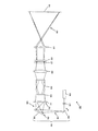
図8はインテグレーダロッド82とリレー光学系83を備えた照明装置の一例を示す図である。インテグレーダロッド82とリレー光学系83は、中間光学系70と被照明領域LZとの間に順に配置されている。
FIG. 8 is a view showing an example of an illuminating device including the
図8のインテグレーダロッド82、リレー光学系83および投射光学系80は、本実施形態に係る投射装置20用に専用に作製されたものではなく、既存のものを流用することを想定している。すなわち、図8の投射装置20は、既存の構成に独自の照明装置40を組み合わせるだけで、上述した各種の効果を得ることができるものであり、既存の構成を流用できることから、設計変更が容易で、設計変更に要するコストと時間を削減できる。
The
図8の投射装置20において、中間光学系70で拡散角度が抑制されたコヒーレント光は、インテグレーダロッド82の入射面に入射される。インテグレーダロッド82は、入射面84から入射された光を、ロッド82内部で全反射させながら伝搬させて、出射面から極めて均一なコヒーレント光を出射する。
In the
インテグレーダロッド82から出射されたコヒーレント光は、リレー光学系83で屈折されて、被照明領域LZを照明する。この照明光は、図1の投射装置20と同様に、光変調器30で変調画像を生成するために用いられ、この変調画像が投射光学系80を経て拡散スクリーン15に投射される。
The coherent light emitted from the
図8は、既存のインテグレーダロッド82、リレー光学系83および投射光学系80に照明装置40を付加して投射装置20を構成するものであり、照明装置40内の中間光学系70とインテグレーダロッド82との位置合わせが重要となる。より具体的には、中間光学系70で屈折されたコヒーレント光がインテグレーダロッド82の入射面内に入射されるように位置合わせを行う必要がある。
FIG. 8 shows the
なお、図8の照明装置40内のホログラム記録媒体55の各点から拡散されたコヒーレント光は中間光学系70の前面を均一に照明するため、インテグレーダロッド82の入射面に入射されるコヒーレント光も均一性が高い。よって、図8の照明装置40を用いる限りは、本来的にはインテグレーダロッド82を用いる必要はないが、上述したように、インテグレーダロッド82を備えた既存の光学システム、例えば投射装置に本実施形態を適用する場合は、インテグレーダロッド82より後段側の光学系をそのまま流用できるため、既存の光学システムに容易に本実施形態を適用することができる。
Note that the coherent light diffused from each point of the
ところで、既存の光学システムの中には、インテグレーダロッド82がないものもある。このような場合にも、本実施形態は容易に適用可能である。例えば図9はインテグレーダロッド82を持たない既存の投射装置に本実施形態を適用した例を示す図である。図9の投射装置20は、図1の投射装置20と比べて、中間光学系70と光変調器の間にリレー光学系83を新たに設けている。このリレー光学系83から投射光学系80までの光学システムは、既存のものを流用することを想定している。
Incidentally, some existing optical systems do not have the
中間光学系70とリレー光学系83の間に仮想的な中間像84が形成される。この中間像84の位置は、図8のインテグレーダロッド82の出射面に対応する位置であり、リレー光学系83は、この中間像84を被照明領域LZに写像する。
A virtual
図9の投射装置は、インテグレーダロッド82を持たないため、中間像84の光強度分布が不均一であると、被照明領域LZの光強度分布も不均一になるが、上述したように、本実施形態に係る照明装置40内のホログラム記録媒体55の各点で拡散されたコヒーレント光は中間光学系70の全域に均等に入射されることから、中間像84の光強度分布は均一になり、インテグレーダロッド82がなくても、実用上問題はない。
Since the projection apparatus of FIG. 9 does not have the
このように、本実施形態に係る照明装置40を既存の投射装置の一部と組み合わせることで、容易にスペックル低減機能を備えた投射装置を構築でき、既存の投射装置からの設計変更に要する時間とコストを短縮できる。
Thus, by combining the
(本実施形態のその他の特徴)
前掲の非特許文献1には、スクリーン上に生じたスペックルの程度を示すパラメータとして、スペックルコントラスト(単位%)という数値を用いる方法が提案されている。このスペックルコントラストは、本来は均一の輝度分布をとるべきテストパターン映像を表示した際に、スクリーン上に実際に生じる輝度のばらつきの標準偏差を、輝度の平均値で除した値として定義される量である。このスペックルコントラストの値が大きければ大きいほど、スクリーン上のスペックル発生程度が大きいことを意味し、観察者に対して、斑点状の輝度ムラ模様がより顕著に提示されていることを示す。
(Other features of this embodiment)
Non-Patent Document 1 mentioned above proposes a method using a numerical value called speckle contrast (unit%) as a parameter indicating the degree of speckle generated on the screen. This speckle contrast is defined as a value obtained by dividing the standard deviation of the actual luminance variation on the screen divided by the average luminance value when displaying a test pattern image that should have a uniform luminance distribution. Amount. The larger the speckle contrast value is, the larger the speckle occurrence level on the screen is, which indicates that the spot-like luminance unevenness pattern is more prominently presented to the observer.
加えて、上述してきた本実施形態によれば、次の利点を享受することもできる。 In addition, according to the above-described embodiment, the following advantages can be obtained.
上述してきた本実施形態によれば、スペックルを目立たなくさせるための光学素子50が、照射装置60から照射されるコヒーレント光のビーム形態を整形および調整するための光学部材としても機能し得る。したがって、光学系を小型且つ簡易化することができる。
According to this embodiment described above, the
また、上述してきた本実施形態によれば、ホログラム記録媒体55の特定位置に入射するコヒーレント光が、被照明領域LZ内の全域に各色で散乱板6の像5を生成する。このため、ホログラム記録媒体55で回折された光をすべて照明用に利用することが可能となり、レーザ光源61からの光の利用効率の面においても優れる。
Further, according to the present embodiment described above, coherent light incident on a specific position of the
(0次光の回避)
照射装置60からのコヒーレント光の一部は、ホログラム記録媒体55で回折されることなく当該ホログラム記録媒体55を透過する。このような光は0次光と呼ばれる。0次光が被照明領域LZに入射してしまうと、周囲と比較して明るさ(輝度)が急激に上昇する点状領域、線状領域、面状領域等の異常領域が被照明領域LZ内に発生してしまう。
(Avoiding zero-order light)
A part of the coherent light from the
反射型のホログラム記録媒体55(以下、反射型ホロ)を用いる場合は、0次光が進行する方向には被照明領域LZは配置されないため、0次光を比較的容易に回避できるが、透過型のホログラム記録媒体55(以下、透過型ホロ)を用いる場合は、0次光を回避する構成は取りづらい。したがって、透過型ホロの場合は、回折効率を極力高くし、0次光の影響をできるだけ抑えるようにするのが望まれる。 In the case of using the reflection type hologram recording medium 55 (hereinafter referred to as reflection type holo), the illuminated region LZ is not arranged in the direction in which the 0th order light travels, so that the 0th order light can be avoided relatively easily. When a hologram recording medium 55 (hereinafter referred to as a transmission type holo) is used, it is difficult to take a configuration that avoids zero-order light. Therefore, in the case of a transmission type holo, it is desired to increase the diffraction efficiency as much as possible and suppress the influence of zero-order light as much as possible.
(反射型と透過型のホログラム記録媒体55)
反射型ホロは、透過型ホロに比べて、波長選択性が高い。すなわち、反射型ホロは、異なる波長に対応した干渉縞を積層させても、所望の層のみで所望の波長のコヒーレント光を回折させることができる。また、0次光の影響を除去しやすい点でも、反射型ホロは優れている。
(Reflective and transmissive hologram recording medium 55)
The reflection type holo has higher wavelength selectivity than the transmission type holo. That is, the reflection type holo can diffract coherent light having a desired wavelength only by a desired layer even if interference fringes corresponding to different wavelengths are laminated. The reflection type holo is also excellent in that it is easy to remove the influence of zero-order light.
一方、透過型ホロは、回折可能なスペクトルが広く、レーザ光源61の許容度が広いが、異なる波長に対応した干渉縞を積層させると、所望の層以外の層でも所望の波長のコヒーレント光が回折されてしまう。よって、一般には、透過型ホロは、積層構造にするのが困難である。
On the other hand, the transmission type holo has a wide diffractable spectrum and a wide tolerance of the
(照射装置60)
上述した形態では、照射装置60が、レーザ光源61と走査デバイス65とを有する例を説明した。走査デバイス65は、コヒーレント光の進行方向を反射によって変化させる一軸回動型のミラーデバイス66からなる例を示したが、これに限られない。走査デバイス65は、図10に示すように、ミラーデバイス66のミラー(反射面66a)が、第1の回動軸線RA1だけでなく、第1の回動軸線RA1と交差する第2の回動軸線RA2を中心としても回動可能となっていてもよい。図10に示された例では、ミラー66aの第2の回動軸線RA2は、ホログラム記録媒体55の板面上に定義されたXY座標系のY軸と平行に延びる第1回動軸線RA1と、直交している。そして、ミラー66aが、第1軸線RA1および第2軸線RA2の両方を中心として回動可能なため、照射装置60からのコヒーレント光の光学素子50への入射点IPは、ホログラム記録媒体55の板面上で二次元方向に移動可能となる。このため、一例として図10に示されているように、コヒーレント光の光学素子50への入射点IPが円周上を移動するようにすることもできる。
(Irradiation device 60)
In the above-described embodiment, the example in which the
また、走査デバイス65が、二以上のミラーデバイス66を含んでいてもよい。この場合、ミラーデバイス66のミラー66aが、単一の軸線を中心としてのみ回動可能であっても、照射装置60からのコヒーレント光の光学素子50への入射点IPを、ホログラム記録媒体55の板面上で二次元方向に移動させることができる。
Further, the
なお、走査デバイス65に含まれるミラーデバイス66aの具体例としては、MEMSミラー、ポリゴンミラー、ガルバノスキャナ等を挙げることができる。
Specific examples of the
また、走査デバイス65は、反射によってコヒーレント光の進行方向を変化させる反射デバイス、すなわち、本実施形態において、一例として上述してきたミラーデバイス66以外のデバイスを含んで構成されていてもよい。例えば、走査デバイス65が、屈折プリズムやレンズ等を含んでいていてもよい。
The
そもそも、走査デバイス65は必須ではなく、照射装置60の光源61が、光学素子50に対して変位可能(移動、揺動、回転)に構成され、光源61の光学素子50に対する変位によって、光源61から照射されたコヒーレント光がホログラム記録媒体55上を走査するようにしてもよい。
In the first place, the
光源61から照射されるコヒーレント光は、理想的には線状光線であるが、実際にはわずかに拡散しており、光源61からのコヒーレント光は、必ずしも走査デバイス65の1点には入射されない。このため、図1に示すように、照射装置60内の光源61と走査デバイス65との間に集光レンズ67を設けてもよい。集光レンズ67は、光源61からのコヒーレント光が走査デバイス65の1点に収束されるように位置決めされる。これにより、走査デバイス65の回転中心とコヒーレント光の発散中心が一致するため、走査デバイス65が回転する際にも、常に基準点SPからの発散光をホログラム記録媒体55に入射することができ、当初意図した通りに被照明領域LZを照明できるようになる。
The coherent light emitted from the
なお、照射装置60の光源61は、必ずしも線状光線として整形されたレーザ光を発振するものではなくてもよい。とりわけ、上述した形態では、光学素子50の各位置に照射されたコヒーレント光は、光学素子50によって、被照明領域LZの全域に入射するようになる光束に整形される。したがって、照射装置60の光源61から光学素子50に照射されるコヒーレント光は精確に整形されていなくとも不都合は生じない。このため、光源61から発生されるコヒーレント光は、発散光であってもよい。また、光源61から発生されるコヒーレント光の断面形状は、円でなく、楕円等であってもよい。さらには、光源61から発生されるコヒーレント光の横モードがマルチモードであってもよい。
The
なお、光源61が発散光束を発生させる場合、コヒーレント光は、光学素子50のホログラム記録媒体55に入射する際に、点ではなくある程度の面積を持った領域に入射することになる。この場合、ホログラム記録媒体55で回折されて被照明領域LZの各位置に入射する光は、角度を多重化されることになる。言い換えると、各瞬間において、被照明領域LZの各位置には、或る程度の角度範囲の方向からコヒーレント光が入射する。このような角度の多重化によって、スペックルをさらに効果的に目立たなくさせることができる。
When the
さらに、図1では、走査デバイス65で反射されたコヒーレント光を直接に光学素子50に入射させる例を示したが、走査デバイス65と光学素子50の間に集光レンズを設けて、この集光レンズでコヒーレント光を平行光束にして光学素子50に入射するようにしてもよい。このような例では、ホログラム記録媒体55を作製する際の露光工程において、参照光Lrとして、上述した収束光束に代えて、平行光束を用いることになる。このようなホログラム記録媒体55は、より簡単に作製および複製することができる。
Further, FIG. 1 shows an example in which the coherent light reflected by the
(光学素子50)
上述した形態において、光学素子50が、フォトポリマーを用いた反射型の体積型ホログラム55からなる例を示したが、これに限られない。また、光学素子50は、銀塩材料を含む感光媒体を利用して記録するタイプの体積型ホログラムを含んでもよい。さらに、光学素子50は、透過型の体積型ホログラム記録媒体55を含んでいてもよいし、レリーフ型(エンボス型)のホログラム記録媒体55を含んでいてもよい。
(Optical element 50)
In the embodiment described above, an example in which the
ただし、レリーフ(エンボス)型ホログラムは、表面の凹凸構造によってホログラム干渉縞の記録が行われる。しかしながら、このレリーフ型ホログラムの場合、表面の凹凸構造による散乱が、光量ロスの原因となるほか、意図しない新たなスペックル生成要因となる可能性があり、この点において体積型ホログラムの方が好ましい。体積型ホログラムでは、媒体内部の屈折率変調パターン(屈折率分布)としてホログラム干渉縞の記録が行われるため、表面の凹凸構造による散乱による影響を受けることはない。 However, in the relief (embossed) hologram, hologram interference fringes are recorded by the concavo-convex structure on the surface. However, in the case of this relief-type hologram, scattering due to the uneven structure on the surface may cause a loss of light amount and may cause a new unintended speckle generation. In this respect, the volume-type hologram is preferable. . In the volume hologram, since the hologram interference fringe is recorded as a refractive index modulation pattern (refractive index distribution) inside the medium, it is not affected by scattering due to the uneven structure on the surface.
もっとも、体積型ホログラムでも、銀塩材料を含む感光媒体を利用して記録するタイプのものは、銀塩粒子による散乱が光量ロスの原因となるほか、意図しない新たなスペックル生成要因となる可能性がある。この点において、ホログラム記録媒体55としては、フォトポリマーを用いた体積型ホログラムの方が好ましい。
However, even volume holograms that are recorded using a photosensitive medium containing silver salt material may cause light loss due to scattering by silver salt particles, and may cause unintended new speckle generation. There is sex. In this respect, the
また、図3に示す記録工程では、いわゆるフレネルタイプのホログラム記録媒体55が作成されることになるが、レンズを用いた記録を行うことにより得られるフーリエ変換タイプのホログラム記録媒体55を作成してもかまわない。ただ、フーリエ変換タイプのホログラム記録媒体55を用いる場合には、像再生時にもレンズを使用してもよい。
In addition, in the recording process shown in FIG. 3, a so-called Fresnel type
また、ホログラム記録媒体55に形成されるべき縞状パターン、例えば屈折率変調パターンや凹凸パターンは、現実の物体光Loおよび参照光Lrを用いることなく、予定した再生照明光Laの波長や入射方向、並びに、再生されるべき像の形状や位置等に基づき計算機を用いて設計されてもよい。このようにして得られたホログラム記録媒体55は、計算機合成ホログラムとも呼ばれる。また上述した変形例のように波長域の互いに異なる複数のコヒーレント光が照射装置60から照射される場合には、計算機合成ホログラムとしてのホログラム記録媒体55は、各波長域のコヒーレント光にそれぞれ対応して設けられた複数の領域に平面的に区分けされ、各波長域のコヒーレント光は対応する領域で回折されて像を再生するようにしてもよい。
Further, the striped pattern to be formed on the
さらに、上述した形態において、光学素子50が、各位置に照射されたコヒーレント光を拡げて、当該拡げたコヒーレント光を用いて被照明領域LZの全域を照明するホログラム記録媒体55を有する例を示したが、これに限られない。光学素子50は、ホログラム記録媒体55に代えて、或いはホログラム記録媒体55に加えて、各位置に照射されたコヒーレント光の進行方向を変化させるとともに拡散させて、被照明領域LZの全域をコヒーレント光で照明する光学要素としてのレンズアレイを有するようにしてもよい。このような具体例として、拡散機能を付与された全反射型または屈折型フレネルレンズや、フライアイレンズ等を挙げることができる。このような照明装置40においても、照射装置60が、レンズアレイ上をコヒーレント光が走査するようにして、光学素子50にコヒーレント光を照射するようにし、且つ、照射装置60から光学素子50の各位置に入射したコヒーレント光が、レンズアレイによって進行方向を変化させられて被照明領域LZを照明するよう、照射装置60および光学素子50を構成しておくことにより、スペックルを効果的に目立たなくさせることができる。
Furthermore, in the embodiment described above, an example is shown in which the
光学素子50は、ホログラム記録媒体55やレンズアレイの他に、拡散板で構成することも可能である。拡散板としては、オパールガラスやすりガラス等のガラス部材、あるいは樹脂拡散板などが考えられる。拡散板は、走査デバイス65で反射されたコヒーレント光を拡散させるため、ホログラム記録媒体55やレンズアレイを用いた場合と同様に、種々の方向から被照明領域LZを照明することができる。なお、本発明における光学素子における「拡散」とは、入射光を所定の方向に角度的に拡げて出射することを指し、回折光学素子やレンズアレイ等による拡散角が十分に制御された場合のみならず、オパールガラス等の散乱粒子により出射角を拡げる場合も含まれるものとする。
In addition to the
(照明方法)
上述した形態において、照射装置60が光学素子50上でコヒーレント光を一次元方向に走査可能とするように構成され、且つ、光学素子50のホログラム記録媒体55またはレンズアレイが各位置に照射されたコヒーレント光を二次元方向に拡散するように構成され、これにより、照明装置40が二次元的な被照明領域LZを照明する例を示した。ただし、既に説明してきたように、このような例に限定されることはなく、例えば、照射装置60が光学素子50上でコヒーレント光を二次元方向に走査可能とするように構成され、且つ、光学素子50のホログラム記録媒体55またはレンズアレイが各位置に照射されたコヒーレント光を二次元方向に拡散するように構成され、これにより、図10に示したように、照明装置40が二次元的な被照明領域LZを照明してもよい。
(Lighting method)
In the embodiment described above, the
また、既に言及しているように、照射装置60が光学素子50上でコヒーレント光を一次元方向に走査可能とするように構成され、且つ、光学素子50のホログラム記録媒体55またはレンズアレイが各位置に照射されたコヒーレント光を一次元方向に拡散するように構成され、これにより、照明装置40が一次元的な被照明領域LZを照明するようにしてもよい。この態様において、照射装置60によるコヒーレント光の走査方向と、光学素子50のホログラム記録媒体55またはレンズアレイの拡散方向と、が平行となるようにしてもよい。
Further, as already mentioned, the
さらに、照射装置60が光学素子50上でコヒーレント光を一次元方向または二次元方向に走査可能とするように構成され、且つ、光学素子50のホログラム記録媒体55またはレンズアレイが各位置に照射されたコヒーレント光を一次元方向に拡散するように構成されていてもよい。この態様において、光学素子50が複数のホログラム記録媒体55またはレンズアレイを有し、各ホログラム記録媒体55またはレンズアレイに対応した被照明領域LZを順に照明していくことによって、照明装置40が二次元的な領域を照明するようにしてもよい。この際、各被照明領域LZが、人間の目では同時に照明されているかのような速度で、順に照明されていってもよいし、あるいは、人間の目でも順番に照明していると認識できるような遅い速度で、順に照明されていってもよい。
Furthermore, the
なお、本明細書では、光学素子50と、照射装置60内の走査デバイス65と、中間光学系70とを合わせたものを投射制御装置90と呼ぶ。
In this specification, a combination of the
本発明の態様は、上述した個々の実施形態に限定されるものではなく、当業者が想到しうる種々の変形も含むものであり、本発明の効果も上述した内容に限定されない。すなわち、特許請求の範囲に規定された内容およびその均等物から導き出される本発明の概念的な思想と趣旨を逸脱しない範囲で種々の追加、変更および部分的削除が可能である。 The aspect of the present invention is not limited to the individual embodiments described above, and includes various modifications that can be conceived by those skilled in the art, and the effects of the present invention are not limited to the contents described above. That is, various additions, modifications, and partial deletions can be made without departing from the concept and spirit of the present invention derived from the contents defined in the claims and equivalents thereof.
15 拡散スクリーン、20 投射装置、30 空間光変調器、40 照明装置、50
光学素子、55 ホログラム記録媒体、58 ホログラム感光材料、60 照射装置、61 光源、65 走査デバイス、66 ミラーデバイス(反射デバイス)、66a ミラー(反射面)、67 集光レンズ、70 中間光学系、80 投射光学系、LZ 被照明領域
15 Diffuser Screen, 20 Projector, 30 Spatial Light Modulator, 40 Illuminator, 50
Optical element, 55 hologram recording medium, 58 hologram photosensitive material, 60 irradiation device, 61 light source, 65 scanning device, 66 mirror device (reflection device), 66a mirror (reflection surface), 67 condenser lens, 70 intermediate optical system, 80 Projection optical system, LZ Illuminated area
Claims (17)
コヒーレント光が前記光学素子上を走査するように、前記コヒーレント光の進行方向を経時的に角度変化させて前記光学素子を照射する照射装置と、
前記照射装置から前記光学素子の各位置に入射されて拡散されたコヒーレント光によって照明される光変調器と、
前記光変調器で生成される変調画像を拡散面に投射する投射光学系と、
前記光学素子と前記光変調器との間に配置され、前記光学素子で拡散されたコヒーレント光の拡散角度を抑制する中間光学系と、を備え、
前記光学素子から拡散されたコヒーレント光は、前記中間光学系にて拡散角度が抑制された後、前記光学素子上の拡散位置によらず、前記光変調器を重ねて照明することを特徴とする投射装置。 An optical element capable of diffusing coherent light;
An irradiation device that irradiates the optical element while changing the traveling direction of the coherent light with time so that the coherent light scans on the optical element;
A light modulator that is illuminated by the coherent light that is incident and diffused from the irradiation device to each position of the optical element;
A projection optical system that projects a modulated image generated by the light modulator onto a diffusion surface;
An intermediate optical system that is disposed between the optical element and the optical modulator and suppresses a diffusion angle of coherent light diffused by the optical element,
The coherent light diffused from the optical element is illuminated by overlapping the light modulator regardless of the diffusion position on the optical element after the diffusion angle is suppressed by the intermediate optical system. Projection device.
コヒーレント光を放射する光源と、
前記光源から放射された前記コヒーレント光の進行方向を変化させて、該コヒーレント光を前記光学素子上で走査させる走査デバイスと、を有することを特徴とする請求項1乃至13のいずれかに記載の投射装置。 The irradiation device includes:
A light source that emits coherent light;
A scanning device that changes a traveling direction of the coherent light emitted from the light source and scans the coherent light on the optical element. Projection device.
前記コヒーレント光の進行方向を経時的に角度変化させて、該コヒーレント光を前記光学素子上で走査させる走査デバイスと、
前記光学素子で拡散されたコヒーレント光の拡散角度を抑制する中間光学系とを備え、
前記光学素子から拡散されたコヒーレント光は、前記中間光学系にて拡散角度が抑制された後、前記光学素子上の拡散位置によらず、被照明領域を重ねて照明することを特徴とする投射制御装置。 An optical element capable of diffusing coherent light;
A scanning device that changes the traveling direction of the coherent light over time, and scans the coherent light on the optical element;
An intermediate optical system that suppresses the diffusion angle of coherent light diffused by the optical element;
The coherent light diffused from the optical element is illuminated by overlapping the illuminated area regardless of the diffusion position on the optical element after the diffusion angle is suppressed by the intermediate optical system. Control device.
Priority Applications (8)
| Application Number | Priority Date | Filing Date | Title |
|---|---|---|---|
| JP2011277134A JP5403044B2 (en) | 2011-04-28 | 2011-12-19 | Projection device and projection control device |
| PCT/JP2012/060632 WO2012147627A1 (en) | 2011-04-28 | 2012-04-19 | Projection device and projection control device |
| CN201510341279.4A CN104898364B (en) | 2011-04-28 | 2012-04-19 | Grenade instrumentation and projection control device |
| CN201510631183.1A CN105116678B (en) | 2011-04-28 | 2012-04-19 | Grenade instrumentation and projection control device |
| EP12777365.3A EP2703886B1 (en) | 2011-04-28 | 2012-04-19 | Projection device and projection control device |
| US14/113,312 US9366946B2 (en) | 2011-04-28 | 2012-04-19 | Projection apparatus and projection control apparatus |
| CN201280020654.XA CN103518161B (en) | 2011-04-28 | 2012-04-19 | Grenade instrumentation and projection control device |
| US15/151,758 US9829781B2 (en) | 2011-04-28 | 2016-05-11 | Projection apparatus and projection control apparatus |
Applications Claiming Priority (3)
| Application Number | Priority Date | Filing Date | Title |
|---|---|---|---|
| JP2011101348 | 2011-04-28 | ||
| JP2011101348 | 2011-04-28 | ||
| JP2011277134A JP5403044B2 (en) | 2011-04-28 | 2011-12-19 | Projection device and projection control device |
Related Child Applications (1)
| Application Number | Title | Priority Date | Filing Date |
|---|---|---|---|
| JP2013225491A Division JP2014067041A (en) | 2011-04-28 | 2013-10-30 | Scanning device, irradiation device, illumination device and projection device |
Publications (3)
| Publication Number | Publication Date |
|---|---|
| JP2012237968A JP2012237968A (en) | 2012-12-06 |
| JP2012237968A5 JP2012237968A5 (en) | 2013-06-06 |
| JP5403044B2 true JP5403044B2 (en) | 2014-01-29 |
Family
ID=47072147
Family Applications (1)
| Application Number | Title | Priority Date | Filing Date |
|---|---|---|---|
| JP2011277134A Active JP5403044B2 (en) | 2011-04-28 | 2011-12-19 | Projection device and projection control device |
Country Status (5)
| Country | Link |
|---|---|
| US (2) | US9366946B2 (en) |
| EP (1) | EP2703886B1 (en) |
| JP (1) | JP5403044B2 (en) |
| CN (3) | CN103518161B (en) |
| WO (1) | WO2012147627A1 (en) |
Families Citing this family (32)
| Publication number | Priority date | Publication date | Assignee | Title |
|---|---|---|---|---|
| KR101225560B1 (en) * | 2010-09-07 | 2013-01-24 | 다이니폰 인사츠 가부시키가이샤 | Illumination device using coherent light source |
| JP5804243B2 (en) * | 2011-04-22 | 2015-11-04 | 大日本印刷株式会社 | Projection-type image display device |
| JP5637931B2 (en) * | 2011-05-17 | 2014-12-10 | キヤノン株式会社 | Imprint apparatus, imprint method, and device manufacturing method |
| US9086618B2 (en) * | 2011-06-10 | 2015-07-21 | Nikon Corporation | Projector having holographic recording medium and light modulation element |
| JP6229928B2 (en) * | 2013-06-27 | 2017-11-15 | 大日本印刷株式会社 | Illumination device and projection device |
| JP6287157B2 (en) * | 2013-12-13 | 2018-03-07 | 大日本印刷株式会社 | Illumination device and projection device |
| JP2015141393A (en) * | 2014-01-30 | 2015-08-03 | 大日本印刷株式会社 | Illumination device and projection device |
| JP2015155950A (en) * | 2014-02-20 | 2015-08-27 | 大日本印刷株式会社 | Illumination device and projection device |
| EP3109688B1 (en) * | 2014-02-21 | 2020-01-08 | Pioneer Corporation | Optical element and heads-up display |
| JP6311971B2 (en) * | 2014-03-25 | 2018-04-18 | 大日本印刷株式会社 | Illumination device, projection device and irradiation device |
| JP6252298B2 (en) * | 2014-03-27 | 2017-12-27 | 大日本印刷株式会社 | Lighting device |
| GB2529613B (en) * | 2014-07-03 | 2020-05-20 | Smidsy Ltd | Vehicle mounted laser projector |
| KR20160018917A (en) * | 2014-08-07 | 2016-02-18 | 현대자동차주식회사 | Lamp for vehicle |
| JP6376348B2 (en) * | 2015-02-20 | 2018-08-22 | ウシオ電機株式会社 | Vehicle driving support device |
| JP2016173391A (en) * | 2015-03-16 | 2016-09-29 | セイコーエプソン株式会社 | Lighting device and projector |
| CN107430280B (en) * | 2015-03-31 | 2020-01-31 | 浜松光子学株式会社 | Projection display device |
| EP3281056A1 (en) * | 2015-04-10 | 2018-02-14 | Essilor International | Head mounted display device |
| CN104777738B (en) * | 2015-04-17 | 2017-08-11 | 四川大学 | A kind of holographic zoom system, pancreatic system for the bad light that disappears |
| CN105204313B (en) * | 2015-08-16 | 2018-07-17 | 四川大学 | A kind of optical focal distance setting system and Zooming method based on programmable orthogonal contiguity cylindrical lens |
| CN107923591B (en) * | 2015-09-07 | 2021-02-19 | 大日本印刷株式会社 | Lighting device |
| US10690911B2 (en) * | 2015-10-09 | 2020-06-23 | Maxell, Ltd. | Projection optical system and head-up display device |
| CN105204312B (en) * | 2015-10-10 | 2018-05-08 | 四川大学 | A kind of holographic projection system based on digital cylindrical lens |
| US10400997B2 (en) * | 2015-11-20 | 2019-09-03 | Dai Nippon Printing Co., Ltd. | Illumination device |
| AT517957B1 (en) * | 2015-12-22 | 2017-06-15 | Zkw Group Gmbh | Method for controlling a motor vehicle headlight |
| US20190082151A1 (en) * | 2016-02-24 | 2019-03-14 | Hon Hai Precision Industry Co., Ltd. | Projector |
| US20190116344A1 (en) * | 2017-10-17 | 2019-04-18 | Visteon Global Technologies, Inc. | Multiple image plane head-up display |
| EP3567851A4 (en) * | 2018-03-12 | 2020-07-29 | Guangdong Oppo Mobile Telecommunications Corp., Ltd. | Projector and test method and device therefor, image acquisition device, electronic device, readable storage medium |
| US11137720B2 (en) | 2018-03-21 | 2021-10-05 | Samsung Display Co., Ltd. | Holographic display device |
| JP6658797B2 (en) * | 2018-05-24 | 2020-03-04 | 日本精機株式会社 | Optical element for head-up display |
| US10880529B2 (en) * | 2019-04-09 | 2020-12-29 | GM Global Technology Operations LLC | Speckle reduction with image dithering |
| JP7417874B2 (en) * | 2019-06-28 | 2024-01-19 | 大日本印刷株式会社 | Lighting device and lighting method |
| CN113047522A (en) * | 2021-03-26 | 2021-06-29 | 吕正兴 | Special high strength board of intelligence building engineering |
Family Cites Families (32)
| Publication number | Priority date | Publication date | Assignee | Title |
|---|---|---|---|---|
| US5313479A (en) | 1992-07-29 | 1994-05-17 | Texas Instruments Incorporated | Speckle-free display system using coherent light |
| US6229648B1 (en) * | 1998-04-06 | 2001-05-08 | Unic View Ltd. | Compact projector |
| US20020071472A1 (en) * | 1999-04-30 | 2002-06-13 | Metrologic Instruments, Inc. | DOE-based systems and devices for producing laser beams having modified beam characteristics |
| US6511186B1 (en) * | 1999-07-09 | 2003-01-28 | Sarnoff Corporation | Focus and aim device and method for image projection |
| US6491396B2 (en) * | 2000-02-15 | 2002-12-10 | Seiko Epson Corporation | Projector modulating a plurality of partial luminous fluxes according to imaging information by means of an electro-optical device |
| US6594090B2 (en) * | 2001-08-27 | 2003-07-15 | Eastman Kodak Company | Laser projection display system |
| GB0223119D0 (en) * | 2002-10-05 | 2002-11-13 | Holographic Imaging Llc | Reconfigurable spatial light modulators |
| GB0226014D0 (en) * | 2002-11-08 | 2002-12-18 | Nokia Corp | Camera-LSI and information device |
| US20050219693A1 (en) * | 2004-04-02 | 2005-10-06 | David Hartkop | Scanning aperture three dimensional display device |
| JP4636315B2 (en) | 2004-04-22 | 2011-02-23 | ソニー株式会社 | One-dimensional illumination device and image generation device |
| DE102004044111B4 (en) * | 2004-09-08 | 2015-05-07 | Seereal Technologies Gmbh | Method and device for coding and reconstructing computer-generated video holograms |
| JP2006137326A (en) | 2004-11-12 | 2006-06-01 | Toyota Motor Corp | Front part structure of car body |
| US8016428B2 (en) | 2005-06-20 | 2011-09-13 | Panasonic Corporation | 2-dimensional image display device or illumination device for obtaining uniform illumination and suppressing speckle noise |
| JP4483763B2 (en) * | 2005-10-19 | 2010-06-16 | セイコーエプソン株式会社 | Illumination device and image display device |
| EP1949186A2 (en) * | 2005-11-15 | 2008-07-30 | California Institute Of Technology | High density, high bandwidth multilevel holographic memory |
| DE102006004300A1 (en) * | 2006-01-20 | 2007-08-02 | Seereal Technologies S.A. | Projection device for holographic reconstruction of scenes, comprises reproduction medium, which is used to reproduce Fourier transformation of light from light source modulated by light modulation device onto screen |
| GB2436676B (en) * | 2006-03-28 | 2008-02-20 | Light Blue Optics Ltd | Holographic display devices |
| JP4963925B2 (en) * | 2006-10-13 | 2012-06-27 | 三菱電機株式会社 | Laser light source device and video display device |
| EP2084583A1 (en) * | 2006-10-26 | 2009-08-05 | SeeReal Technologies S.A. | Compact holographic display device |
| JP2008175869A (en) | 2007-01-16 | 2008-07-31 | Seiko Epson Corp | Light source device, illumination device, monitor device, image display device, and projector |
| JP2008224760A (en) | 2007-03-08 | 2008-09-25 | Seiko Epson Corp | Projector |
| JP4333760B2 (en) | 2007-03-23 | 2009-09-16 | セイコーエプソン株式会社 | Hologram element, illumination device and projector |
| EP1975679A1 (en) | 2007-03-31 | 2008-10-01 | Sony Deutschland Gmbh | Image generating apparatus |
| JP4552956B2 (en) | 2007-04-03 | 2010-09-29 | セイコーエプソン株式会社 | Lighting device and projector |
| JP4379482B2 (en) * | 2007-04-03 | 2009-12-09 | セイコーエプソン株式会社 | Light source device and projector |
| JP2008304726A (en) | 2007-06-08 | 2008-12-18 | Hitachi Ltd | Scanning type image display apparatus |
| JP2009151221A (en) * | 2007-12-21 | 2009-07-09 | Seiko Epson Corp | Illuminator, image display apparatus, and polarization conversion/diffusion member |
| JP5223452B2 (en) | 2008-05-20 | 2013-06-26 | 株式会社リコー | Projector, projection image forming method, and vehicle head-up display device |
| JP5157835B2 (en) | 2008-11-12 | 2013-03-06 | セイコーエプソン株式会社 | Image display device |
| JP2010271663A (en) | 2009-05-25 | 2010-12-02 | Hoya Corp | Electrostatically-driven optical scanner |
| JP5402393B2 (en) | 2009-08-20 | 2014-01-29 | 大日本印刷株式会社 | Projection-type image display device and image display method |
| JP2010160491A (en) | 2010-01-22 | 2010-07-22 | Seiko Epson Corp | Method of adjusting optical scanner |
-
2011
- 2011-12-19 JP JP2011277134A patent/JP5403044B2/en active Active
-
2012
- 2012-04-19 US US14/113,312 patent/US9366946B2/en active Active
- 2012-04-19 CN CN201280020654.XA patent/CN103518161B/en not_active Expired - Fee Related
- 2012-04-19 EP EP12777365.3A patent/EP2703886B1/en active Active
- 2012-04-19 CN CN201510631183.1A patent/CN105116678B/en active Active
- 2012-04-19 WO PCT/JP2012/060632 patent/WO2012147627A1/en active Application Filing
- 2012-04-19 CN CN201510341279.4A patent/CN104898364B/en active Active
-
2016
- 2016-05-11 US US15/151,758 patent/US9829781B2/en active Active
Also Published As
| Publication number | Publication date |
|---|---|
| US9366946B2 (en) | 2016-06-14 |
| WO2012147627A1 (en) | 2012-11-01 |
| CN103518161A (en) | 2014-01-15 |
| EP2703886A4 (en) | 2014-11-05 |
| CN104898364A (en) | 2015-09-09 |
| EP2703886A1 (en) | 2014-03-05 |
| JP2012237968A (en) | 2012-12-06 |
| CN105116678A (en) | 2015-12-02 |
| CN105116678B (en) | 2017-12-15 |
| CN104898364B (en) | 2018-01-19 |
| US20160252804A1 (en) | 2016-09-01 |
| EP2703886B1 (en) | 2019-07-31 |
| US9829781B2 (en) | 2017-11-28 |
| CN103518161B (en) | 2015-11-25 |
| US20140043591A1 (en) | 2014-02-13 |
Similar Documents
| Publication | Publication Date | Title |
|---|---|---|
| JP5403044B2 (en) | Projection device and projection control device | |
| JP6304337B2 (en) | Illumination device, projection device, and projection-type image display device | |
| JP6179553B2 (en) | Lighting device | |
| JP6226252B2 (en) | Illumination device, projection device, and projection-type image display device | |
| JP6128174B2 (en) | Lighting device | |
| JP5741341B2 (en) | Projection device and hologram recording medium | |
| JP5737619B2 (en) | Projection device | |
| JP5924578B2 (en) | Illumination device, projection device, and projection-type image display device | |
| JP5765032B2 (en) | Illumination device, projection device, and projection-type image display device | |
| JP5510826B2 (en) | Illumination device, projection device, and projection-type image display device | |
| JP5982993B2 (en) | Hologram manufacturing apparatus and hologram manufacturing method | |
| JP5807802B2 (en) | Projection device | |
| JP2014067041A (en) | Scanning device, irradiation device, illumination device and projection device | |
| JP6057193B2 (en) | Lighting device |
Legal Events
| Date | Code | Title | Description |
|---|---|---|---|
| A521 | Written amendment |
Free format text: JAPANESE INTERMEDIATE CODE: A523 Effective date: 20130419 |
|
| A621 | Written request for application examination |
Free format text: JAPANESE INTERMEDIATE CODE: A621 Effective date: 20130419 |
|
| A871 | Explanation of circumstances concerning accelerated examination |
Free format text: JAPANESE INTERMEDIATE CODE: A871 Effective date: 20130419 |
|
| A975 | Report on accelerated examination |
Free format text: JAPANESE INTERMEDIATE CODE: A971005 Effective date: 20130517 |
|
| A131 | Notification of reasons for refusal |
Free format text: JAPANESE INTERMEDIATE CODE: A131 Effective date: 20130628 |
|
| A521 | Written amendment |
Free format text: JAPANESE INTERMEDIATE CODE: A523 Effective date: 20130827 |
|
| TRDD | Decision of grant or rejection written | ||
| A01 | Written decision to grant a patent or to grant a registration (utility model) |
Free format text: JAPANESE INTERMEDIATE CODE: A01 Effective date: 20131001 |
|
| A61 | First payment of annual fees (during grant procedure) |
Free format text: JAPANESE INTERMEDIATE CODE: A61 Effective date: 20131014 |
|
| R150 | Certificate of patent or registration of utility model |
Ref document number: 5403044 Country of ref document: JP Free format text: JAPANESE INTERMEDIATE CODE: R150 |
|
| RD02 | Notification of acceptance of power of attorney |
Free format text: JAPANESE INTERMEDIATE CODE: R3D02 |