JP5390943B2 - Image processing apparatus and image processing method - Google Patents
Image processing apparatus and image processing method Download PDFInfo
- Publication number
- JP5390943B2 JP5390943B2 JP2009135357A JP2009135357A JP5390943B2 JP 5390943 B2 JP5390943 B2 JP 5390943B2 JP 2009135357 A JP2009135357 A JP 2009135357A JP 2009135357 A JP2009135357 A JP 2009135357A JP 5390943 B2 JP5390943 B2 JP 5390943B2
- Authority
- JP
- Japan
- Prior art keywords
- face
- image
- luminance
- correction
- image processing
- Prior art date
- Legal status (The legal status is an assumption and is not a legal conclusion. Google has not performed a legal analysis and makes no representation as to the accuracy of the status listed.)
- Active
Links
- 238000012545 processing Methods 0.000 title claims description 80
- 238000003672 processing method Methods 0.000 title claims description 9
- 238000012937 correction Methods 0.000 claims description 70
- 238000001514 detection method Methods 0.000 claims description 25
- 238000000034 method Methods 0.000 claims description 21
- 238000000605 extraction Methods 0.000 claims description 13
- 239000000284 extract Substances 0.000 claims description 8
- 230000035945 sensitivity Effects 0.000 claims description 5
- 230000006870 function Effects 0.000 claims description 4
- 230000001815 facial effect Effects 0.000 description 19
- 238000003384 imaging method Methods 0.000 description 9
- 238000004364 calculation method Methods 0.000 description 8
- 229920006395 saturated elastomer Polymers 0.000 description 8
- 238000007906 compression Methods 0.000 description 6
- 230000006835 compression Effects 0.000 description 6
- 238000005286 illumination Methods 0.000 description 6
- 238000010586 diagram Methods 0.000 description 5
- 230000010354 integration Effects 0.000 description 5
- 238000006243 chemical reaction Methods 0.000 description 4
- 230000006837 decompression Effects 0.000 description 4
- 238000013075 data extraction Methods 0.000 description 3
- 230000007717 exclusion Effects 0.000 description 3
- 238000012546 transfer Methods 0.000 description 3
- 238000011161 development Methods 0.000 description 2
- 238000009434 installation Methods 0.000 description 2
- 230000003287 optical effect Effects 0.000 description 2
- 238000012935 Averaging Methods 0.000 description 1
- 230000003044 adaptive effect Effects 0.000 description 1
- 238000013528 artificial neural network Methods 0.000 description 1
- 238000013144 data compression Methods 0.000 description 1
- 230000007423 decrease Effects 0.000 description 1
- 230000007274 generation of a signal involved in cell-cell signaling Effects 0.000 description 1
- 238000003780 insertion Methods 0.000 description 1
- 230000037431 insertion Effects 0.000 description 1
- 239000004973 liquid crystal related substance Substances 0.000 description 1
- 239000004065 semiconductor Substances 0.000 description 1
- 238000007619 statistical method Methods 0.000 description 1
- 238000012795 verification Methods 0.000 description 1
Images


Classifications
-
- G—PHYSICS
- G06—COMPUTING; CALCULATING OR COUNTING
- G06T—IMAGE DATA PROCESSING OR GENERATION, IN GENERAL
- G06T7/00—Image analysis
-
- G—PHYSICS
- G06—COMPUTING; CALCULATING OR COUNTING
- G06V—IMAGE OR VIDEO RECOGNITION OR UNDERSTANDING
- G06V40/00—Recognition of biometric, human-related or animal-related patterns in image or video data
- G06V40/10—Human or animal bodies, e.g. vehicle occupants or pedestrians; Body parts, e.g. hands
- G06V40/16—Human faces, e.g. facial parts, sketches or expressions
- G06V40/161—Detection; Localisation; Normalisation
-
- G—PHYSICS
- G06—COMPUTING; CALCULATING OR COUNTING
- G06T—IMAGE DATA PROCESSING OR GENERATION, IN GENERAL
- G06T5/00—Image enhancement or restoration
-
- G—PHYSICS
- G06—COMPUTING; CALCULATING OR COUNTING
- G06V—IMAGE OR VIDEO RECOGNITION OR UNDERSTANDING
- G06V10/00—Arrangements for image or video recognition or understanding
- G06V10/40—Extraction of image or video features
- G06V10/50—Extraction of image or video features by performing operations within image blocks; by using histograms, e.g. histogram of oriented gradients [HoG]; by summing image-intensity values; Projection analysis
- G06V10/507—Summing image-intensity values; Histogram projection analysis
-
- H—ELECTRICITY
- H04—ELECTRIC COMMUNICATION TECHNIQUE
- H04N—PICTORIAL COMMUNICATION, e.g. TELEVISION
- H04N23/00—Cameras or camera modules comprising electronic image sensors; Control thereof
- H04N23/60—Control of cameras or camera modules
- H04N23/61—Control of cameras or camera modules based on recognised objects
- H04N23/611—Control of cameras or camera modules based on recognised objects where the recognised objects include parts of the human body
-
- H—ELECTRICITY
- H04—ELECTRIC COMMUNICATION TECHNIQUE
- H04N—PICTORIAL COMMUNICATION, e.g. TELEVISION
- H04N25/00—Circuitry of solid-state image sensors [SSIS]; Control thereof
- H04N25/60—Noise processing, e.g. detecting, correcting, reducing or removing noise
- H04N25/62—Detection or reduction of noise due to excess charges produced by the exposure, e.g. smear, blooming, ghost image, crosstalk or leakage between pixels
- H04N25/625—Detection or reduction of noise due to excess charges produced by the exposure, e.g. smear, blooming, ghost image, crosstalk or leakage between pixels for the control of smear
-
- H—ELECTRICITY
- H04—ELECTRIC COMMUNICATION TECHNIQUE
- H04N—PICTORIAL COMMUNICATION, e.g. TELEVISION
- H04N25/00—Circuitry of solid-state image sensors [SSIS]; Control thereof
- H04N25/60—Noise processing, e.g. detecting, correcting, reducing or removing noise
- H04N25/62—Detection or reduction of noise due to excess charges produced by the exposure, e.g. smear, blooming, ghost image, crosstalk or leakage between pixels
Landscapes
- Engineering & Computer Science (AREA)
- Multimedia (AREA)
- Physics & Mathematics (AREA)
- Theoretical Computer Science (AREA)
- General Physics & Mathematics (AREA)
- Signal Processing (AREA)
- Health & Medical Sciences (AREA)
- Human Computer Interaction (AREA)
- Oral & Maxillofacial Surgery (AREA)
- General Health & Medical Sciences (AREA)
- Computer Vision & Pattern Recognition (AREA)
- Studio Devices (AREA)
- Image Processing (AREA)
- Collating Specific Patterns (AREA)
- Image Analysis (AREA)
Description
本発明は画像処理装置及び画像処理方法に関し、特に顔認証に用いるための特徴量データの抽出が可能な画像処理装置及び画像処理方法に関する。 The present invention relates to an image processing apparatus and an image processing method, and more particularly to an image processing apparatus and an image processing method capable of extracting feature amount data for use in face authentication.
従来、人間の顔を撮影して得られた画像データから、認証処理を行う顔照合装置が知られている。顔照合装置は、固体撮像素子を用いた撮像装置で撮像された認証対象者の顔画像の入力を受け付ける。顔照合装置は、顔画像から、目、鼻、口、輪郭等、認証対象者の顔部品の特徴量を示す認証者特徴量データを取得する。そして、顔照合装置は、事前に記憶された登録者の登録者特徴量データの各々について認証者特徴量データと照合し、その認証対象者の登録者に対する類似度を求める。そして、認証対象者を、ここで求めた類似度が最大であった登録者であると認証する。 2. Description of the Related Art Conventionally, a face matching device that performs authentication processing from image data obtained by photographing a human face is known. The face collation device accepts input of a face image of a person to be authenticated imaged by an imaging device using a solid-state imaging device. The face matching device acquires authenticator feature value data indicating the feature values of the facial parts of the person to be authenticated, such as eyes, nose, mouth, and contour, from the face image. Then, the face collation device collates each registrant feature quantity data of the registrant stored in advance with the certifier feature quantity data, and obtains the similarity of the certifier to the registrant. Then, the person to be authenticated is authenticated as a registrant who has obtained the maximum similarity.
なお、最大であった類似度が予め定められた認証閾値よりも小さければ、認証対象者を未登録者であるとする(認証対象者を登録者であると認証しない)。また、最大の類似度が認証閾値と同じであった場合、認証対象者を登録者であるとするか、未登録者であるとするかについては、どちらかに決められている。 If the maximum similarity is smaller than a predetermined authentication threshold, it is determined that the person to be authenticated is an unregistered person (the person to be authenticated is not authenticated as a registrant). Further, when the maximum similarity is the same as the authentication threshold value, it is determined whether the authentication target person is a registered person or an unregistered person.
顔照合装置は、例えば、施設のドアの施錠/開錠の制御装置に認証結果を供給し、制御装置が、認証結果に応じてドアの施錠/開錠を行う。また、ATM(Automated Teller Machine)で取引する利用者の特定に、顔照合装置を利用することも提案されている。具体的には、ATMに撮像装置を取り付けておき、この撮像装置で撮像した利用者の顔画像を用いて利用者を特定することが提案されている。このようにすることで、これまで利用者の認証に利用していたカード(例えば、キャッシュカード)の挿入や、暗証番号の入力等の操作を不要にし、操作性の向上を図ることができる。 For example, the face matching device supplies an authentication result to a door locking / unlocking control device of a facility, and the control device locks / unlocks the door according to the authentication result. In addition, it has also been proposed to use a face matching device to identify users who trade with ATM (Automated Teller Machine). Specifically, it has been proposed that an imaging device is attached to an ATM and a user is specified using a user's face image captured by the imaging device. By doing so, operations such as insertion of a card (for example, a cash card) that has been used for user authentication and input of a personal identification number are unnecessary, and operability can be improved.
ところで、従来の顔照合装置は、登録者を正面から撮像した顔画像から得た登録者特徴量データを記憶している。一方、照合時に撮像される認証対象者の顔画像における照明条件(照明の向き、明るさ、色等)は、撮像装置の設置環境や、撮像時における認証対象者の姿勢により決まる。このため、撮像装置の設置環境によっては、撮像された認証対象者の顔画像から取得した認証者特徴量データと、この認証対象者について記憶している登録者特徴量データとの類似度が小さくなることがある。その結果、登録者である認証対象者を未登録者であると誤判別することがある。 Incidentally, the conventional face matching device stores registrant feature amount data obtained from a face image obtained by imaging a registrant from the front. On the other hand, the illumination conditions (illumination direction, brightness, color, etc.) in the face image of the authentication subject imaged at the time of verification are determined by the installation environment of the imaging device and the posture of the authentication subject person at the time of imaging. For this reason, depending on the installation environment of the imaging device, the degree of similarity between the certifier feature amount data acquired from the captured face image of the authentication subject and the registrant feature amount data stored for the authentication subject is small. May be. As a result, an authentication target person who is a registrant may be misidentified as an unregistered person.
なお、登録者である認証対象者を未登録者であるとする誤判別の発生確率(所謂、誤排除率)を抑えるには、認証閾値を低めに設定すればよい。しかし、認証閾値を低めに設定すると、逆に、登録者でない認証対象者を登録者であるとする誤判別の発生確率(所謂、誤受入率)が増大し、セキュリティレベルを低下させてしまう。このため、認証閾値は、顔照合装置が適用されるシステムにおいて確保すべきセキュリティレベルに応じて設定される。具体的には、確保すべきセキュリティレベルの高いシステムほど、認証閾値を高く設定し、誤排除率の低減よりも誤受入率の低減を優先させている。 Note that the authentication threshold value may be set to a low value in order to suppress the occurrence probability of misjudgment that the registrant to be authenticated is an unregistered person (so-called false exclusion rate). However, if the authentication threshold is set low, the probability of misjudgment (so-called false acceptance rate) that the authentication target person who is not the registrant is the registrant increases, and the security level is lowered. For this reason, the authentication threshold is set according to the security level to be secured in the system to which the face matching device is applied. Specifically, the higher the security level to be secured, the higher the authentication threshold is set, and the reduction of the false acceptance rate is given priority over the reduction of the false exclusion rate.
誤排除率と誤受入率の両者を低減させて、認証精度を向上させるため、1人の登録者について、照明条件が異なる複数の顔画像から得た登録者特徴量データを記憶することが開示されている(特許文献1参照)。具体的には、登録者の顔画像を3Dモデル画像(3次元モデル画像)とし、この3Dモデル画像から照明条件が異なる複数の2Dモデル画像(2次元モデル画像)を生成する。そして、生成した複数の2Dモデル画像から取得した登録者特徴量データを記憶するというものである。 Disclosure of storing registrant feature data obtained from multiple face images with different lighting conditions for one registrant in order to reduce both false exclusion rate and false acceptance rate and improve authentication accuracy (See Patent Document 1). Specifically, a registrant's face image is used as a 3D model image (3D model image), and a plurality of 2D model images (2D model images) with different illumination conditions are generated from the 3D model image. And the registrant feature-value data acquired from the produced | generated several 2D model image are memorize | stored.
しかしながら、特許文献1では、1人の登録者について照明条件が異なる複数の顔画像から得た、複数の登録者特徴量データを記憶する必要があり、登録作業が非常に煩わしいという課題があった。
そして、これは登録者特徴量データを記憶するときのみならず、登録者特徴量データとの類似度を求めるための認証者特徴量データを求めるときについても、同様の課題が存在する。すなわち、認証者特徴量データを求めるときも、照明条件の影響を排除するためには、照明条件を変えながら複数の顔画像から認証者特徴量データを求める必要が生じてしまうという課題があった。
However, in
This is not only when storing registrant feature data, but also when obtaining certifier feature data for determining the similarity to registrant feature data. That is, when obtaining the authenticator feature data, there is a problem that it is necessary to obtain the authenticator feature data from a plurality of face images while changing the illumination conditions in order to eliminate the influence of the illumination conditions. .
本発明はこのような従来技術の課題に鑑みなされたものであり、複数の顔画像データを用いずとも、高い認証精度が得られる特徴量データを抽出できる画像処理装置及び画像処理方法を提供することを1つの目的とする。 The present invention has been made in view of the above-described problems of the prior art, and provides an image processing apparatus and an image processing method capable of extracting feature amount data with high authentication accuracy without using a plurality of face image data. This is one purpose.
上述の目的は、画像から、人間の顔を検出する顔検出手段と、顔検出手段が検出した顔の領域内の輝度を求め、画像に対して、顔の領域内の輝度のばらつきを抑制する補正を行う輝度補正手段と、輝度補正手段にて補正された画像の顔の領域から顔部品を検出し、顔部品の特徴量データを、認証に用いるための特徴量データとして抽出する抽出手段とを有し、輝度補正手段は、顔の領域を複数のブロックに分割し、ブロックごとに求めた輝度値と予め定めた1つの輝度値との比較結果に基づいて、顔の領域内の画素に対して補正を行うことを特徴とする画像処理装置によって達成される。 The above-described object is to obtain a face detection unit for detecting a human face from an image and the luminance within the face area detected by the face detection unit, and suppress variations in luminance within the face region with respect to the image. a luminance correcting means for correcting, extraction means for detecting a face part from the area of the face of the corrected image by the luminance correction means, for extracting feature data of the face parts, as feature amount data for use in authenticating And the brightness correction unit divides the face area into a plurality of blocks, and the pixels in the face area are based on a comparison result between the brightness value obtained for each block and a predetermined brightness value. This is achieved by an image processing apparatus characterized by correcting the image.
また、上述の目的は、顔検出手段が、画像から、人間の顔を検出する顔検出工程と、輝度補正手段が、検出した顔の領域内の輝度を求め、画像に対して、顔の領域内の輝度のばらつきを抑制する補正を行う輝度補正工程と、抽出手段が、輝度のばらつきを抑制する補正が行われた画像の顔の領域から顔部品を検出し、顔部品の特徴量データを、認証に用いるための特徴量データとして抽出する抽出工程とを有し、輝度補正工程で輝度補正手段は、顔の領域を複数のブロックに分割し、ブロックごとに求めた輝度値と予め定めた1つの輝度値との比較結果に基づいて、顔の領域内の画素に対して補正を行うことを特徴とする画像処理方法によっても達成される。 Further, the above-described object is that the face detection unit detects a human face from the image, and the luminance correction unit obtains the luminance within the detected face region, and the face region A luminance correction step for performing correction to suppress the luminance variation in the image, and the extracting means detects the facial component from the face area of the image subjected to the correction for suppressing the luminance variation, and the feature amount data of the facial component is obtained. , and a extraction step of extracting as a feature amount data to be used for authentication, the luminance correcting means luminance correcting step divides the face area into a plurality of blocks, predetermined luminance value determined for each block The image processing method is also characterized in that correction is performed on pixels in the face area based on the result of comparison with a single luminance value.
このような構成により、本発明によれば、複数の顔画像データを用いずとも、高い認証精度が得られる特徴量データを抽出できる画像処理装置及び画像処理方法が実現できる。 With such a configuration, according to the present invention, it is possible to realize an image processing apparatus and an image processing method capable of extracting feature amount data with high authentication accuracy without using a plurality of face image data.
(第1の実施形態)
以下、図面を参照して本発明の好適且つ例示的な実施形態について詳細に説明する。
図1は、本発明の第1の実施形態に係る画像処理装置の一例としての、デジタルカメラの構成を示す図である。
(First embodiment)
Hereinafter, preferred and exemplary embodiments of the present invention will be described in detail with reference to the drawings.
FIG. 1 is a diagram showing a configuration of a digital camera as an example of an image processing apparatus according to the first embodiment of the present invention.
撮像素子14は、CCDやCMOSセンサの光電変換素子で構成され、撮影レンズ10を透過した光学像を電気信号に変換する。A/D変換器16は、撮像素子14のアナログ信号の出力をデジタル信号に変換する。
タイミング発生部18は、撮像素子14、A/D変換器16、D/A変換器26にクロック信号や制御信号を供給する。
The
The
画像処理部20は、A/D変換器16からのデータ、或いは、メモリ制御部22からのデータに対して所定の画素補間処理や色変換処理を行う。
また、画像処理部20においては、撮像した画像データを用いて所定の演算処理を行う。この所定の演算処理については後述する。
The
Further, the
メモリ制御部22は、A/D変換器16、タイミング発生部18、画像処理部20、画像表示メモリ24、D/A変換器26、メモリ30、圧縮伸張部32を制御する。
A/D変換器16の出力データは、メモリ制御部22を介して、画像表示メモリ24或いはメモリ30に書き込まれる。
The
The output data of the A /
画像表示メモリ24に書き込まれた表示用の画像データは、D/A変換器26を介してLCD(Liquid Crystal Display)や有機ELディスプレイ等で構成された画像表示部28により表示される。撮像した画像データを画像表示部28で逐次表示すれば、被写体の像をリアルタイムで表示する電子ファインダ機能を実現することが可能である。
The display image data written in the
メモリ30は撮影した静止画像や動画像を格納する記憶装置であり、所定枚数の静止画像や所定時間の動画像を格納するのに十分な記憶容量を備えている。そのため、複数枚の静止画像を連続して撮影する連写撮影の場合にも、高速かつ大量の画像書き込みをメモリ30に対して行うことが可能となる。また、メモリ30はシステム制御部50の作業領域としても使用することが可能である。
The
圧縮伸張部32は、メモリ30に格納された画像を読み込んで、適応離散コサイン変換(ADCT)、ウェーブレット変換等を用いた周知のデータ圧縮処理或いは伸張処理を行い、処理を終えたデータをメモリ30に書き込む。
The compression /
システム制御部50は例えばCPUであり、メモリ52に記憶されたプログラムを実行することによりデジタルカメラ100全体を制御する。メモリ52はシステム制御部50の動作用の定数、変数、プログラム等を記憶する。
The
不揮発性メモリ56は電気的に消去・記録可能なメモリであり、例えばEEPROM等が用いられる。
操作部70は、システム制御部50に各種の動作指示を入力するための操作手段を構成する。
The
The
第1シャッタースイッチSW1(62)は、デジタルカメラ100に設けられたシャッターボタン(図示せず)の第1ストローク(例えば半押し)でオンとなる。第1シャッタースイッチSW1(62)がオンになると、システム制御部50は、合焦制御、露出制御、および、調光制御等の動作開始を不図示の回路に指示する。
The first shutter switch SW1 (62) is turned on by a first stroke (for example, half-pressed) of a shutter button (not shown) provided in the
第2シャッタースイッチ(SW2)64は、デジタルカメラ100に設けられたシャッターボタンの第2ストローク(例えば全押し)でONとなり、露光処理、現像処理及び記録処理からなる一連の処理の開始を指示する。まず、露光処理では、撮像素子14から読み出した信号をA/D変換器16、メモリ制御部22を介して画像データをメモリ30に書き込み、更に、画像処理部20やメモリ制御部22での演算を用いた現像処理が行われる。更に、メモリ30から画像データを読み出し、圧縮伸張部32で圧縮を行い、外部記録媒体120に画像データを書き込む記録処理が行われる。
The second shutter switch (SW2) 64 is turned on by a second stroke (for example, full press) of a shutter button provided in the
本実施形態において、JPEG圧縮のモードにおいては、圧縮伸張部32が、メモリ30に書き込まれた画像データを読み出し、設定された圧縮率に圧縮した後、外部記録媒体120に記録する。
RAWモードでは、撮像素子14の色フィルタの画素配列に応じて、ライン毎にそのまま画像データを読み出し、A/D変換器16、メモリ制御部22を介して、メモリ30に書き込まれた画像データを読み出し、外部記録媒体120に記録する。
In the present embodiment, in the JPEG compression mode, the compression /
In the RAW mode, the image data is read as it is for each line according to the pixel arrangement of the color filter of the
インタフェース91は、画像処理部20やメモリ制御部22と、外部記録媒体120とのインタフェースである。
The
顔認証部101は、画像処理部20で処理された画像データや画像表示メモリ24に保存されている撮像画像データを解析し、撮像画像に含まれる人間の顔を検出する。具体的には、顔認証部101は、人間の顔と思われる領域(顔領域)を検出する。顔認証部101は、顔領域が検出された場合には、人間の顔と思われる確からしさ(信頼度)、画像中の位置、サイズなどを、顔領域情報として出力する。また、顔認証部101は、検出した顔領域について、目、鼻、口、輪郭等の顔部品(特徴点)の特徴量を示す登録者特徴量データ(辞書データ)を算出し、出力する。
The
外部記録媒体120は、不揮発性半導体メモリカード、カード型ハードディスク等であり、デジタルカメラ100に対して着脱可能である。
The
本実施形態のデジタルカメラ100は、撮像画像から人間の顔の領域を検出し、目、鼻、口、輪郭等の顔部品の特徴量を示す特徴量データ(顔認証に用いるための辞書データ)を生成する。顔領域の検出及び特徴量データの生成は、上述の通り顔認証部101で行う。
The
本実施形態では、この特徴量データの生成処理を行う際に、斜光や逆光で撮像された画像など、光源と顔との位置関係によって顔に影がある場合には、影の領域に対して部分階調補正を実施してから特徴量データの生成を行うことを特徴とする。
また、部分階調補正は、8ビット以上の階調を有するガンマ補正前の信号、具体的にはRAW信号で実施することで、階調とびを防ぎ、より精度の高い辞書データが取得できる。
In this embodiment, when the feature amount data generation process is performed, if there is a shadow on the face due to the positional relationship between the light source and the face, such as an image captured by oblique light or backlight, Characteristic amount data is generated after partial gradation correction is performed.
Further, partial gradation correction is performed with a signal before gamma correction having a gradation of 8 bits or more, specifically, a RAW signal, thereby preventing gradation skipping and acquiring dictionary data with higher accuracy.
本実施形態において、顔認証部101は、画像表示部28をリアルタイムで被写体を観察するために用いる電子ビューファインダー(EVF)として機能させるために生成した表示用画像から、辞書データを取得する。
In the present embodiment, the
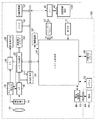
図2は、本実施形態のデジタルカメラ100において、特徴量データの取得に関わる構成について詳細に示したブロック図である。また、図3は、図2の動作を説明するためのフローチャートである。図2、図3を用いて、本実施形態のデジタルカメラ100における特徴量データの取得動作について説明する。
FIG. 2 is a block diagram showing in detail a configuration related to the acquisition of feature data in the
図3のS101において、撮像素子14は予め設定された周期(ここでは1/30秒に1回)で被写体(不図示)の撮影を行い、撮影画像に対応した画像信号を出力する。
In S101 of FIG. 3, the
S102において、撮像素子14から読み出されたアナログ画像信号をA/D変換器16はデジタル画像信号に変換し、メモリ30は一時的に記録する。この時点での画像信号をRAW信号またはRAWデータと呼ぶ。
In S102, the analog image signal read from the
S103において、OB処理部204は撮像素子14のオプチカルブラック領域のデータを用いて、RAW信号の黒レベルを0とする黒レベル補正処理を行う。また、WB(ホワイトバランス)処理部205は、周知のオートホワイトバランス補正処理により、光源を推定し、白色レベルを調整するために各色信号に乗じるゲイン(WBゲイン)を求める。そして、WB処理部205はWBゲインをRAW信号に適用する。
In step S <b> 103, the
S104において、WBゲイン適用後の信号はYUV変換処理部206でRGB信号からYUV信号に変換される。RGB信号とは、撮像素子14のR(Red)、G(Green)、B(Blue)それぞれの色フィルタに対応した画素の出力値で表した信号であり、YUV信号とは、輝度信号(Y)と、色差信号(U、V)で表した信号である。また、リサイズ処理部207は、YUV信号の縦横比を1:1にリサイズし、画像表示メモリ24に書き込む。S101〜S104の処理を1/30秒周期で繰り返すことで、画像表示部28は30フレーム/秒でYUV信号を用いて撮影画像を表示し、EVFとして機能する。
In S104, the signal after applying the WB gain is converted from an RGB signal to a YUV signal by the YUV
S105において、リサイズ処理部207からのYUV信号、即ち表示用画像を表す信号は顔検出処理部209にも供給される。顔検出処理部209は、表示用画像から人間の顔と思われる画像領域(顔領域)を検出し、その大きさや画像中の位置、信頼度などの情報を顔検出結果としてブロック積分処理部210へ出力する。
In step S <b> 105, the YUV signal from the
なお、本実施形態における顔検出には、公知の顔検出技術を利用できる。
公知の顔検出技術としては、ニューラルネットワークなどを利用した学習に基づく手法、テンプレートマッチングを用いて目、鼻、口等の形状に特徴のある部位を画像から探し出し、類似度が高ければ顔とみなす手法などがある。また、他にも、肌の色や目の形といった画像特徴量を検出し、統計的解析を用いた手法等、多数提案されている。一般的にはこれらの手法を複数組み合わせ、顔検出の精度を向上させている。
具体的な例としては特開2002−251380号公報に記載のウェーブレット変換と画像特徴量を利用して顔検出する方法などが挙げられる。
A known face detection technique can be used for face detection in the present embodiment.
As a known face detection technique, a method based on learning using a neural network or the like, template matching is used to search a part having a characteristic shape of eyes, nose, mouth, etc. from an image, and if the degree of similarity is high, it is regarded as a face There are methods. In addition, many other methods have been proposed, such as a method that detects image feature amounts such as skin color and eye shape and uses statistical analysis. In general, a plurality of these methods are combined to improve the accuracy of face detection.
Specific examples include a face detection method using wavelet transform and image feature amount described in JP-A-2002-251380.
S106以下の処理では、検出された顔領域内の輝度のばらつきを抑制する補正を行い、顔領域内の影の影響を軽減させる。
S106において、ブロック積分処理部210は、顔検出処理部209からの顔検出結果に従い、顔領域を矩形状と見なして、図4に示すようなブロックに分割する。ブロックの大きさは、例えば、平均的な大きさの顔領域が予め定めた数に分割されるように予め定めておくことができる。
In the processing of S106 and subsequent steps, correction for suppressing the luminance variation in the detected face area is performed to reduce the influence of the shadow in the face area.
In S106, the block
本実施形態では、分割したブロックの位置を、左上隅のブロックについて(0,0)とした2次元座標で表すものとする。図4の例では、顔領域を水平7ブロック、垂直8ブロックの計56ブロックに分割しており、ブロックの座標は(0,0)から(6,7)である。 In the present embodiment, it is assumed that the position of the divided block is represented by two-dimensional coordinates with (0, 0) for the block at the upper left corner. In the example of FIG. 4, the face area is divided into a total of 56 blocks of 7 horizontal blocks and 8 vertical blocks, and the coordinates of the blocks are (0,0) to (6,7).
S107において、ブロック積分処理部210は、各ブロックに重みを設定する。本実施形態では、目の付近より上のブロックの重みを0、また、背景が含まれるブロックの重みを0し、それ以外のブロックの重みを1と設定する。なお、以下の説明では、ブロック(x,y)の重みをBLW[x][y]と表記する。
In S107, the block
図5は、図4のブロック(0,4)〜(6,7)までに設定する重みの例を示す図である。目から上のブロック(0,0)〜(6,3)までは演算に用いないため、図5では記載を省略している。また、以下の説明で、全ブロックとは演算に用いるブロックの全て、すなわちブロック(0,4)〜(6,7)を意味し、ブロック(0,0)〜(6,3)は含まれない。 FIG. 5 is a diagram illustrating an example of weights set for blocks (0, 4) to (6, 7) in FIG. Since the blocks (0,0) to (6,3) from the top are not used for the calculation, the description is omitted in FIG. In the following description, all blocks mean all blocks used for computation, that is, blocks (0,4) to (6,7), and blocks (0,0) to (6,3) are included. Absent.
S108において、ブロック積分処理部210は、ブロック毎に、輝度平均値を算出する。なお、以下の説明では、ブロック(x,y)の平均輝度をYAV[x][y]と表記する。図6に、ブロック(0,4)〜(6,7)について算出した輝度平均値の例を示す。
In S108, the block
S109において、ブロック積分処理部210は、S107及びS108にて算出したブロック重みBLW[x][y]と各ブロックの輝度平均値YAV[x][y]とを用いて、顔領域内の輝度平均値AYAVを算出する。
AYAV = (YAV[0][4]×BLW[0][4]+YAV[0][5]×BLW[0][5]+・・・YAV[6][3]×BLW[6][3])/(BLW[0][4]+・・・BLW[6][3])
In S109, the block
AYAV = (YAV [0] [4] × BLW [0] [4] + YAV [0] [5] × BLW [0] [5] + ・ ・ ・ YAV [6] [3] × BLW [6] [3]) / (BLW [0] [4] + ・ ・ ・ BLW [6] [3])
図7は、各ブロックについてブロック重みBLW[x][y]と各ブロックの輝度平均値YAV[x][y]とを乗じた値を示している。従って、図7の各ブロックの値の合計(1510)を、重みの合計値(22)で除すことにより輝度平均値AYAV(68.6)が得られる。 FIG. 7 shows a value obtained by multiplying the block weight BLW [x] [y] and the luminance average value YAV [x] [y] of each block for each block. Therefore, the luminance average value AYAV (68.6) is obtained by dividing the sum (1510) of the values of each block in FIG. 7 by the total weight value (22).
S110において、補正ゲイン算出処理部211は、ブロックごとの輝度平均値を予め定めた1つの輝度値にするための補正ゲインを算出する。本実施形態では、ブロックごとの輝度平均値を全ブロックの輝度平均値にするための補正ゲイン(ブロック補正ゲイン)を求める。
In S110, the correction gain
以下の式を用いてブロック(x,y)の補正ゲインCGA[x][y]を算出する。なお、重みが0のブロックについては、補正しない(すなわち、補正ゲイン=1)とする。
CGA[x][y] = AYAV / YAV[x][y] (BLW[x][y]>0)
CGA[x][y] = 1 (BLW[x][y]=0)
The correction gain CGA [x] [y] of the block (x, y) is calculated using the following equation. It should be noted that a block having a weight of 0 is not corrected (that is, correction gain = 1).
CGA [x] [y] = AYAV / YAV [x] [y] (BLW [x] [y]> 0)
CGA [x] [y] = 1 (BLW [x] [y] = 0)
図8(a)は、平均輝度値AYAVが68.6である場合に算出されるブロック補正ゲインの例を示している。
なお、このブロック補正ゲインは、必ずしも平均輝度値を用いて求める必要はない。例えば、顔領域としての適正輝度値を予め設定しておいて、ブロックごとの輝度平均値をこの適正輝度値にするためのブロック補正ゲインを求めるようにしてもよい。
図8(b)は、適正輝度値が120である場合に算出されるブロック補正ゲインの例を示している。
FIG. 8A shows an example of the block correction gain calculated when the average luminance value AYAV is 68.6.
Note that the block correction gain is not necessarily obtained using the average luminance value. For example, an appropriate luminance value as a face area may be set in advance, and a block correction gain for setting the average luminance value for each block to the appropriate luminance value may be obtained.
FIG. 8B shows an example of the block correction gain calculated when the appropriate luminance value is 120.
S111において、補正ゲイン算出処理部211は、ブロック補正ゲインの平均値CGAAverageを、以下のように算出する。
CGAAverage = (CGA[0][4]+CGA[0][5]+・・・CGA[6][3])/28
In S111, the correction gain
CGAAverage = (CGA [0] [4] + CGA [0] [5] + ・ ・ ・ CGA [6] [3]) / 28
S112において、補正ゲイン算出処理部211は、図9に示すように予め設定した、撮影感度ごとの補正ゲイン上限値と補正ゲイン平均値とを比較する。そして、補正ゲイン算出処理部211は、補正ゲイン平均値が上限値を超える場合、現在の画像から特徴量データは取得しないことを決定し、次の撮影動作に処理を戻す。これは、ゲインの値が大きくなるにつれて補正後の画像のノイズが増大するため、特徴量データの信頼性が低下するためである。撮影感度が高いほど、もともとのゲインが大きいため、補正ゲインは小さいことが望ましい。従って、撮影感度が高いほど上限値は小さく設定する。
In S112, the correction gain
S113において、一方、補正ゲイン平均値が上限値以下であれば、補正ゲイン算出処理部211は、ブロック単位であるブロック補正ゲインから、線形補間などの補間処理によってブロック内の画素毎の補正ゲイン(画素補正ゲイン)を算出する。
On the other hand, if the average correction gain value is equal to or less than the upper limit value in S113, the correction gain
S114において、輝度補正処理部212は、ブロック内の画素に画素補正ゲインを乗算して、輝度補正を行う。
S115において、YUV変換処理部213は、輝度補正後の画像信号をYUV信号へ変換する。
S116において、リサイズ処理部214は、YUV信号の縦横比が1:1となるようリサイズ処理する。
In S114, the luminance
In S115, the YUV
In S116, the resizing
S117において、特徴点抽出処理部215は、リサイズ後のYUV信号と顔検出結果とに基づいて、周知の方法により、目、鼻、口、輪郭等、認証対象者の顔部品と、その特徴量データを抽出する。
S118において、デジタルカメラ100が、抽出した特徴量データを辞書データとして登録する辞書登録モードに設定されていれば、S119に進む。デジタルカメラ100が、画像から抽出した特徴量データを、不揮発性メモリ56に辞書データとして既に記録されている特徴量データと照合する認証モードに設定されていれば、S120に進む。
In S117, the feature point
If the
S119において、特徴点抽出処理部215は、抽出した特徴量データを、例えば不揮発性メモリ56に、辞書データとして記録する。
S120において、特徴点抽出処理部215は、抽出した特徴量データを特徴量データ比較部216に出力する。特徴量データ比較部216は、不揮発性メモリ56からすべての辞書データを読み出し、特徴点抽出処理部215から出力された特徴量データとの類似度を算出する。そして、読み出した辞書データのうち、最も類似度の高かった辞書データと、特徴点抽出処理部215から出力された特徴量データとが同一人物であると判断することで、認証を行う。
In S119, the feature point
In S120, the feature point
このように、本実施形態によれば、顔認証に必要な特徴量データを抽出するための画像に対し、顔領域の輝度補正を行ってから特徴量データを抽出する。従って、逆光や斜光などの環境下で撮像された画像など、照明条件などにより顔に影などが発生した場合でも、その影響を軽減した、精度の良い辞書データを登録することができる。 As described above, according to the present embodiment, the feature amount data is extracted after correcting the brightness of the face region with respect to the image for extracting the feature amount data necessary for face authentication. Therefore, even when a shadow or the like is generated on the face due to illumination conditions, such as an image captured in an environment such as backlight or oblique light, it is possible to register accurate dictionary data with reduced influence.
また、輝度補正処理をガンマ補正前のRAW信号の状態で実施することにより、輝度補正による階調とびの発生が抑制され、目、鼻、口、輪郭等の顔部品について、精度の良い特徴量データを取得することが可能になる。 In addition, by performing the luminance correction processing in the state of the RAW signal before gamma correction, the occurrence of gradation skip due to luminance correction is suppressed, and accurate feature quantities for facial parts such as eyes, nose, mouth, and contours are suppressed. Data can be acquired.
また、辞書データとして登録する特徴量データを抽出する場合の動作のみならず、登録済みの辞書データを用いて顔認証する際にも、輝度補正処理を適用した画像から特徴量データを抽出することで、認証精度を向上させることができる。 Also, not only when extracting feature value data to be registered as dictionary data, but also when extracting face feature data using registered dictionary data, feature value data is extracted from an image to which brightness correction processing has been applied. Thus, the authentication accuracy can be improved.
(第2の実施形態)
次に、本発明の第2の実施形態について説明する。
本実施形態に係る画像処理装置は、目、鼻、口、輪郭等、認証対象者の顔部品の特徴量を示す登録者特徴量データ(辞書データ)を抽出する際に、顔領域におけるスミアの発生を検出し、スミアの影響のない顔部品の特徴量を算出することを特徴とする。
(Second Embodiment)
Next, a second embodiment of the present invention will be described.
When the image processing apparatus according to the present embodiment extracts registrant feature amount data (dictionary data) indicating the feature amount of the face part of the person to be authenticated, such as eyes, nose, mouth, and contour, smear of the face area is extracted. It is characterized in that occurrence is detected and a feature amount of a facial part that is not affected by smear is calculated.
本実施形態においても、第1の実施形態と同様の構成を有するデジタルカメラ100を用いることが可能であるため、構成についての重複する説明は省略し、辞書データとして登録する特徴量データ抽出動作について説明する。
Also in this embodiment, since it is possible to use the
図10は、本実施形態の画像処理装置としてのデジタルカメラ100の、特徴量データの抽出処理を説明するフローチャートである。本実施形態においても、顔認証に用いるための、顔部品の特徴量データ(辞書データ)を表示用画像を用いて抽出するものとする。
FIG. 10 is a flowchart for explaining feature amount data extraction processing of the
まず、第1の実施形態におけるS101〜S104と同様にして、EVF表示用の画像の撮影からYUV信号の生成、リサイズ処理までが行われる。 First, similarly to S101 to S104 in the first embodiment, from EVF display image capturing to YUV signal generation and resizing processing are performed.
S105において、YUV信号は顔検出処理部209(図2)に供給され、人間の顔領域が検出される。
S904において、画像処理部20は、スミア発生量を算出する。
図11は、撮像素子14を、便宜上、水平方向26画素×垂直方向30画素の受光画素110と、水平方向26画素×垂直3画素のスミア検出用の遮光画素112を備えた構成として示す図である。以下の説明において、水平方向m番目、垂直方向n番目の画素の出力値をPIX(m,n)と記述する。
In S105 , the YUV signal is supplied to the face detection processing unit 209 (FIG. 2), and a human face area is detected.
In step S904, the
FIG. 11 is a diagram showing the
スミアは撮像素子14がCCDである場合に、飽和画素からの電荷が垂直転送路に漏れこむことによって発生する。そのため、垂直転送路に沿って伝播し、例えば図のX座標7から9までの列方向の全ての画素がスミアの影響を受ける。また、遮光画素112は遮光されているため通常その出力は0であるが、スミアが発生すると、CCDの垂直転送動作によってスミアが伝播し、0より大きな値を出力するようになる。よって、スミア検出領域の出力画素値を縦方向に加算平均することで、各列におけるスミア発生量SME[m]を算出できる。
Smear is generated when charge from a saturated pixel leaks into the vertical transfer path when the
例えば0列目のスミア発生量SME[0]は、
SME[0]= (PIX(0,30)+PIX(0,31)+PIX(0,32))/3
で算出できる。
For example, the smear generation amount SME [0] in the 0th column is
SME [0] = (PIX (0,30) + PIX (0,31) + PIX (0,32)) / 3
It can be calculated by
図11の例では、7列目から9列目にスミアが発生しており、その値が例えば
SME[7] = 400
SME[8] = 400
SME[9] = 200 (いずれも10ビットA/Dの場合)
である場合を示している。
In the example of FIG. 11, smear has occurred in the 7th to 9th columns, and the value is, for example,
SME [7] = 400
SME [8] = 400
SME [9] = 200 (both for 10-bit A / D)
The case is shown.
なお、本実施形態において、スミア発生量の算出は、画像処理部20が行う。
また、画像処理部20は、スミア発生量に加え、スミア発生領域及び飽和画素領域も検出する。スミア発生領域と飽和画素領域は、スミア発生が検出された列における画素値に基づいて検出することができる。
In the present embodiment, the
Further, the
次に、S905において、画像処理部20は、列毎に算出したスミア値を、対応する列に含まれる全ての画素の値から減算し、スミアによる画素値の増加分を補正する。すなわち、
PIX(m,n) = PIX(m,n) - SME[m]
との演算を行う。
In step S <b> 905, the
PIX (m, n) = PIX (m, n)-SME [m]
And the operation.
S906において、第1の実施形態において説明したように、周知の手法を用いて、顔認証に必要な顔部品とその特徴量データを抽出する。
S907において、顔検出処理部209が顔検出結果として出力する顔領域の位置に関する情報(顔座標)が、顔領域を含む矩形領域の対角点座標であるとする。そして、図11に示す例において、顔検出処理部209が顔座標として、座標(5,2)と座標(18,27)を出力したとする。
In step S <b> 906, as described in the first embodiment, a facial part necessary for face authentication and its feature amount data are extracted using a known method.
In S907, it is assumed that the information (face coordinates) regarding the position of the face area output as the face detection result by the face
図11の例では、座標(7,1)と座標(9,29)を対角頂点とする矩形領域にスミアが発生している。また、7列目と8列目の受光画素はスミア発生により画素値がすべて1023(10ビットのA/D変換器16を用いた場合)と飽和しており、9列目はスミア値が比較的小さく、画素値が1023以下(800)となる場合を例にとる。
In the example of FIG. 11, smear occurs in a rectangular area having coordinates (7, 1) and coordinates (9, 29) as diagonal vertices. The light receiving pixels in the 7th and 8th columns are all saturated with 1023 (when 10-bit A /
本実施形態において、特徴点抽出処理部215は、スミア補正後の顔画像より顔部品を抽出するとともに、スミア補正前に画素値が飽和していた領域を含んだ顔部品は特徴量データの抽出対象から除外することを特徴としている。
In the present embodiment, the feature point
図11の例では、顔部品のうち、右目及び右ほお輪郭信号はスミアにより飽和した画像を含んでいるため、顔部品として抽出できても、その特徴量データを辞書データとして登録しない。この場合、特徴量データの抽出は行うが、登録しない方法、特徴量データの抽出自体を行わない方法のいずれでもよい。一方、口については、右端が9列目のスミア発生領域に掛かっているが、9列目の画素は飽和していないので、スミア補正後の画像から顔部品として抽出され、特徴量データの抽出も行う。従って、図11の例においては、口、左目、鼻、左ほお輪郭信号の特徴量データが抽出され、辞書データとして登録される。なお、顔部品の種類は本発明と直接関係しないため、これらの顔部品は単なる例示であり、他の顔部品の抽出を排除したり、例示した顔部品の全ての抽出が必須であることを示す意図はない。 In the example of FIG. 11, among the facial parts, the right eye and right cheek contour signals include images saturated by smear, so even if they can be extracted as facial parts, their feature data is not registered as dictionary data. In this case, although feature quantity data is extracted, either a method that does not register or a method that does not perform feature quantity data extraction itself may be used. On the other hand, for the mouth, the right end is in the smear generation region in the ninth column, but the pixels in the ninth column are not saturated. Therefore, the image is extracted as a facial part from the smear corrected image, and the feature amount data is extracted. Also do. Therefore, in the example of FIG. 11, the feature amount data of the mouth, left eye, nose, and left cheek contour signals are extracted and registered as dictionary data. Since the types of facial parts are not directly related to the present invention, these facial parts are merely examples, and it is necessary to exclude the extraction of other facial parts or to extract all of the exemplified facial parts. There is no intention to show.
以上説明したように、本実施形態によれば、撮像画像から顔認証に必要な辞書データを登録する際、撮像画像中のスミア発生領域を検出し、スミア補正後の画像に対して顔部品及び特徴量データの抽出を行う。そのため、外光などの強い光源下においても、スミアの影響が少ない、より精度の高い辞書データを登録することが可能となる。 As described above, according to the present embodiment, when registering dictionary data necessary for face authentication from a captured image, a smear generation region in the captured image is detected, and a facial component and a smear correction image are detected from the image after smear correction. Extract feature data. Therefore, even under a strong light source such as outside light, it is possible to register more accurate dictionary data with less smearing.
また、スミア補正前の飽和画素領域を含む顔部品は、特徴量データの登録対象から除外するので、認証に用いる特徴量データの登録量を削減することができるほか、特徴量データの精度を向上させることができ、認証精度の向上を実現することができる。
さらに、辞書データを登録するときのみならず、登録済みの辞書データを用いて顔認証する際にも、同様の処理を適用した画像から特徴量データを抽出することができ、認証精度の向上が実現できる。
In addition, facial parts that include saturated pixel areas before smear correction are excluded from the feature data registration target, so the amount of feature data used for authentication can be reduced, and the accuracy of feature data is improved. The authentication accuracy can be improved.
Furthermore, not only when dictionary data is registered, but also when face authentication is performed using registered dictionary data, feature amount data can be extracted from an image to which similar processing is applied, which improves the authentication accuracy. realizable.
上述の実施形態では、デジタルカメラにて本発明を実施する例をあげて説明を行ったが、これに限定されるものではない。デジタルビデオカメラで本発明を実施することももちろん可能である。また、装着された記録媒体や受けとった画像データや、ネットワークを介して受信した画像データから、顔の特徴量データを検出するようにすれば、パーソナルコンピュータ上のアプリケーションにおいても本発明を実施することが可能である。 In the above-described embodiment, the description has been given by taking an example in which the present invention is implemented with a digital camera. However, the present invention is not limited to this. It is of course possible to implement the present invention with a digital video camera. In addition, if face feature data is detected from a mounted recording medium, received image data, or image data received via a network, the present invention can be implemented in an application on a personal computer. Is possible.
Claims (11)
前記顔検出手段が検出した顔の領域内の輝度を求め、前記画像に対して、前記顔の領域内の輝度のばらつきを抑制する補正を行う輝度補正手段と、
前記輝度補正手段にて補正された画像の前記顔の領域から顔部品を検出し、前記顔部品の特徴量データを、認証に用いるための特徴量データとして抽出する抽出手段とを有し、
前記輝度補正手段は、前記顔の領域を複数のブロックに分割し、該ブロックごとに求めた輝度値と予め定めた1つの輝度値との比較結果に基づいて、前記顔の領域内の画素に対して前記補正を行うことを特徴とする画像処理装置。 Face detection means for detecting a human face from an image;
Luminance correction means for obtaining luminance in the face area detected by the face detection means, and correcting the image to suppress variations in luminance in the face area;
Detecting the face face parts from regions of the corrected image by the luminance correction means, the feature amount data of the face parts, and a extracting means for extracting a feature quantity data for use in authentication,
The brightness correction unit divides the face area into a plurality of blocks, and determines the pixels in the face area based on a comparison result between a brightness value obtained for each block and a predetermined brightness value. An image processing apparatus, wherein the correction is performed on the image processing apparatus.
前記ブロックの輝度平均値を予め定めた1つの輝度値とするための補正ゲインを前記ブロックごとに求め、
前記ブロックごとの補正ゲインから画素ごとの画素補正ゲインを生成し、前記画素補正ゲインを前記ブロック内の画素に適用して前記補正を行うことを特徴とする請求項1に記載の画像処理装置。 The brightness correction means is
A correction gain for making the luminance average value of the block one predetermined luminance value is obtained for each block,
The image processing apparatus according to claim 1, wherein a pixel correction gain for each pixel is generated from the correction gain for each block, and the correction is performed by applying the pixel correction gain to the pixels in the block.
前記抽出手段は、前記平均値が予め定めた値を超える場合には、前記特徴量データの抽出を行わないことを特徴とする請求項2に記載の画像処理装置。 The brightness correction means obtains an average value of the correction gain,
The image processing apparatus according to claim 2, wherein the extraction unit does not extract the feature amount data when the average value exceeds a predetermined value.
輝度補正手段が、検出した前記顔の領域内の輝度を求め、前記画像に対して、前記顔の領域内の輝度のばらつきを抑制する補正を行う輝度補正工程と、
抽出手段が、輝度のばらつきを抑制する補正が行われた画像の前記顔の領域から顔部品を検出し、前記顔部品の特徴量データを、認証に用いるための特徴量データとして抽出する抽出工程とを有し、
前記輝度補正工程で前記輝度補正手段は、前記顔の領域を複数のブロックに分割し、該ブロックごとに求めた輝度値と予め定めた1つの輝度値との比較結果に基づいて、前記顔の領域内の画素に対して前記補正を行うことを特徴とする画像処理方法。 A face detection step in which the face detection means detects a human face from the image;
A luminance correction step, wherein the luminance correction means obtains the luminance in the detected face area, and corrects the image to suppress variation in luminance in the face area;
Extracting means detects a face part from the region of the face image suppressing correcting variation of luminance was performed, and extracts the feature data of the face parts, as feature amount data for use in authentication extract A process,
In the luminance correction step, the luminance correction means divides the face area into a plurality of blocks, and based on a comparison result between the luminance value obtained for each block and a predetermined luminance value, An image processing method comprising performing the correction on a pixel in a region.
Priority Applications (6)
| Application Number | Priority Date | Filing Date | Title |
|---|---|---|---|
| JP2009135357A JP5390943B2 (en) | 2008-07-16 | 2009-06-04 | Image processing apparatus and image processing method |
| KR1020090062826A KR101115370B1 (en) | 2008-07-16 | 2009-07-10 | Image processing apparatus and image processing method |
| US12/501,703 US8401328B2 (en) | 2008-07-16 | 2009-07-13 | Image processing apparatus and image processing method |
| EP13175811.2A EP2650824B1 (en) | 2008-07-16 | 2009-07-15 | Image processing apparatus and image processing method |
| EP09165597A EP2146306A3 (en) | 2008-07-16 | 2009-07-15 | Image processing apparatus and image processing method |
| CN2009101585702A CN101631200B (en) | 2008-07-16 | 2009-07-16 | Image processing apparatus and image processing method |
Applications Claiming Priority (3)
| Application Number | Priority Date | Filing Date | Title |
|---|---|---|---|
| JP2008185293 | 2008-07-16 | ||
| JP2008185293 | 2008-07-16 | ||
| JP2009135357A JP5390943B2 (en) | 2008-07-16 | 2009-06-04 | Image processing apparatus and image processing method |
Related Child Applications (1)
| Application Number | Title | Priority Date | Filing Date |
|---|---|---|---|
| JP2013129995A Division JP5568166B2 (en) | 2008-07-16 | 2013-06-20 | Image processing apparatus and image processing method |
Publications (3)
| Publication Number | Publication Date |
|---|---|
| JP2010045770A JP2010045770A (en) | 2010-02-25 |
| JP2010045770A5 JP2010045770A5 (en) | 2012-07-19 |
| JP5390943B2 true JP5390943B2 (en) | 2014-01-15 |
Family
ID=41232288
Family Applications (1)
| Application Number | Title | Priority Date | Filing Date |
|---|---|---|---|
| JP2009135357A Active JP5390943B2 (en) | 2008-07-16 | 2009-06-04 | Image processing apparatus and image processing method |
Country Status (5)
| Country | Link |
|---|---|
| US (1) | US8401328B2 (en) |
| EP (2) | EP2650824B1 (en) |
| JP (1) | JP5390943B2 (en) |
| KR (1) | KR101115370B1 (en) |
| CN (1) | CN101631200B (en) |
Families Citing this family (26)
| Publication number | Priority date | Publication date | Assignee | Title |
|---|---|---|---|---|
| US8447132B1 (en) | 2009-12-09 | 2013-05-21 | CSR Technology, Inc. | Dynamic range correction based on image content |
| US8953233B2 (en) * | 2010-06-14 | 2015-02-10 | Canon Kabushiki Kaisha | Image reading apparatus and image data processing method |
| JP5796185B2 (en) * | 2011-03-10 | 2015-10-21 | パナソニックIpマネジメント株式会社 | Object judgment device |
| DE102011104198A1 (en) * | 2011-06-15 | 2012-12-20 | Abb Ag | Method for image-based automatic exposure correction |
| KR101896386B1 (en) * | 2011-11-22 | 2018-09-11 | 삼성전자주식회사 | Device and method for adjusting white balance |
| JP6016489B2 (en) * | 2012-07-09 | 2016-10-26 | キヤノン株式会社 | Image processing apparatus, image processing apparatus control method, and program |
| JP6074182B2 (en) * | 2012-07-09 | 2017-02-01 | キヤノン株式会社 | Image processing apparatus, image processing method, and program |
| JP6039942B2 (en) * | 2012-07-09 | 2016-12-07 | キヤノン株式会社 | Information processing apparatus, control method thereof, and program |
| EP3016013A4 (en) * | 2013-06-25 | 2016-10-26 | Fujitsu Ltd | Information processing device, terminal device, information processing program, and information processing method |
| US9454827B2 (en) * | 2013-08-27 | 2016-09-27 | Qualcomm Incorporated | Systems, devices and methods for tracking objects on a display |
| CN103854624B (en) * | 2014-03-17 | 2016-04-27 | 深圳市华星光电技术有限公司 | A kind of driving method of liquid crystal indicator and a kind of liquid crystal indicator |
| US9613575B2 (en) | 2014-03-17 | 2017-04-04 | Shenzhen China Star Optoelectronics Technology Co., Ltd | Liquid crystal display device and method for driving the liquid crystal display device |
| EP3103380A4 (en) * | 2014-09-09 | 2017-11-29 | Olympus Corporation | Endoscope system and method for operating endoscope system |
| US9712744B2 (en) | 2014-11-13 | 2017-07-18 | Intel Corporation | Image quality compensation system and method |
| JP6722878B2 (en) * | 2015-07-30 | 2020-07-15 | パナソニックIpマネジメント株式会社 | Face recognition device |
| JP6664163B2 (en) * | 2015-08-05 | 2020-03-13 | キヤノン株式会社 | Image identification method, image identification device, and program |
| CN106780626B (en) * | 2016-12-21 | 2019-03-05 | 维沃移动通信有限公司 | A kind of method and mobile terminal of camera parameter regulation |
| DE102017003170A1 (en) * | 2017-03-31 | 2018-10-04 | MAX-PLANCK-Gesellschaft zur Förderung der Wissenschaften e.V. | Method and apparatus for correcting smear artifacts |
| CN107343156B (en) * | 2017-07-10 | 2020-03-13 | Oppo广东移动通信有限公司 | Adjusting method and device for automatic exposure control of face area |
| KR102397396B1 (en) * | 2017-09-13 | 2022-05-12 | 삼성전자주식회사 | Image processing method and device for auto white balance |
| CN109670389B (en) * | 2017-10-16 | 2023-04-07 | 富士通株式会社 | Method and equipment for evaluating illumination condition in face image |
| CN110503504B (en) * | 2019-03-14 | 2022-02-15 | 杭州海康威视数字技术股份有限公司 | Information identification method, device and equipment of network product |
| US10944898B1 (en) * | 2019-09-19 | 2021-03-09 | Capital One Services, Llc | Systems and methods for guiding image sensor angle settings in different environments |
| CN110738175B (en) * | 2019-10-17 | 2022-08-02 | 北京旷视科技有限公司 | Face image processing method and device, computer equipment and storage medium |
| JP2021124881A (en) * | 2020-02-04 | 2021-08-30 | ローランド株式会社 | Image processing apparatus, image processing program, and image processing method |
| WO2023048153A1 (en) * | 2021-09-24 | 2023-03-30 | テルモ株式会社 | Information processing method, computer program, and information processing device |
Family Cites Families (30)
| Publication number | Priority date | Publication date | Assignee | Title |
|---|---|---|---|---|
| JPS60112376A (en) * | 1983-11-22 | 1985-06-18 | Sanyo Electric Co Ltd | Image pickup device |
| US6809763B1 (en) * | 1999-08-02 | 2004-10-26 | Olympus Optical Co., Ltd. | Image pickup apparatus and method of correcting deteriorated pixel signal thereof |
| JP2001202516A (en) * | 2000-01-19 | 2001-07-27 | Victor Co Of Japan Ltd | Device for individual identification |
| KR20020014593A (en) * | 2000-08-18 | 2002-02-25 | 최진영 | Module for certifying a right user of a personal portable phone and method for certifying the right user using the same |
| JP2002251380A (en) | 2001-02-22 | 2002-09-06 | Omron Corp | User collation system |
| KR20040042500A (en) * | 2002-11-14 | 2004-05-20 | 엘지전자 주식회사 | Face detection based on pca-lda |
| US7365880B2 (en) * | 2003-04-04 | 2008-04-29 | Kabushiki Kaisha Toshiba | Image processing apparatus and image processing method |
| JP4639037B2 (en) | 2003-07-18 | 2011-02-23 | キヤノン株式会社 | Image processing method and apparatus |
| JP4412929B2 (en) | 2003-07-30 | 2010-02-10 | セコム株式会社 | Face detection device |
| JP2005056004A (en) | 2003-08-07 | 2005-03-03 | Omron Corp | Unit, method and program for face collation |
| JP2005086516A (en) * | 2003-09-09 | 2005-03-31 | Canon Inc | Imaging device, printer, image processor and program |
| JP4448304B2 (en) | 2003-09-11 | 2010-04-07 | セコム株式会社 | Face detection device |
| KR20060020998A (en) * | 2004-09-02 | 2006-03-07 | (주)제니텀 엔터테인먼트 컴퓨팅 | Method for detecting a face and apparatus thereof |
| WO2006030519A1 (en) | 2004-09-17 | 2006-03-23 | Mitsubishi Denki Kabushiki Kaisha | Face identification device and face identification method |
| US20060152606A1 (en) * | 2005-01-07 | 2006-07-13 | Nucore Technology, Inc. | Displaying a smear leakage icon on the display of a digital camera |
| US7936919B2 (en) * | 2005-01-18 | 2011-05-03 | Fujifilm Corporation | Correction of color balance of face images depending upon whether image is color or monochrome |
| US7715649B2 (en) * | 2005-02-14 | 2010-05-11 | Fujifilm Corporation | Generation and adjustment of a luminance correction curve to prevent saturation of the image during contrast enhancement |
| WO2007072907A1 (en) * | 2005-12-21 | 2007-06-28 | Nec Corporation | Gray-scale correcting method, gray-scale correcting device, gray-scale correcting program, and image device |
| JP4639271B2 (en) * | 2005-12-27 | 2011-02-23 | 三星電子株式会社 | camera |
| JP4768448B2 (en) * | 2006-01-13 | 2011-09-07 | 富士フイルム株式会社 | Imaging device |
| JP2007201963A (en) * | 2006-01-30 | 2007-08-09 | Victor Co Of Japan Ltd | Imaging apparatus |
| JP2007241682A (en) * | 2006-03-09 | 2007-09-20 | Seiko Epson Corp | Processing of image data for printing |
| JP2008005365A (en) * | 2006-06-26 | 2008-01-10 | Victor Co Of Japan Ltd | Imaging device |
| JP2008059197A (en) * | 2006-08-30 | 2008-03-13 | Canon Inc | Apparatus, method, computer program and storage medium for collating image |
| EP2061233B1 (en) | 2006-09-14 | 2013-06-26 | Mitsubishi Electric Corporation | Image processing device and image processing method |
| KR100810344B1 (en) * | 2006-10-10 | 2008-03-04 | 삼성전자주식회사 | Apparatus for digital photographing and method for smear appearance correction and detecting using the same |
| WO2008056777A1 (en) * | 2006-11-10 | 2008-05-15 | Konica Minolta Holdings, Inc. | Authentication system and authentication method |
| JP4845796B2 (en) | 2007-04-10 | 2011-12-28 | キヤノン株式会社 | IMAGING DEVICE AND IMAGING DEVICE CONTROL METHOD |
| JP5202375B2 (en) | 2009-02-16 | 2013-06-05 | キヤノン株式会社 | Imaging apparatus, image processing method, and program |
| JP4741019B2 (en) | 2009-07-06 | 2011-08-03 | セコム株式会社 | Intercom device |
-
2009
- 2009-06-04 JP JP2009135357A patent/JP5390943B2/en active Active
- 2009-07-10 KR KR1020090062826A patent/KR101115370B1/en active IP Right Grant
- 2009-07-13 US US12/501,703 patent/US8401328B2/en active Active
- 2009-07-15 EP EP13175811.2A patent/EP2650824B1/en not_active Not-in-force
- 2009-07-15 EP EP09165597A patent/EP2146306A3/en not_active Withdrawn
- 2009-07-16 CN CN2009101585702A patent/CN101631200B/en active Active
Also Published As
| Publication number | Publication date |
|---|---|
| EP2146306A2 (en) | 2010-01-20 |
| KR101115370B1 (en) | 2012-02-16 |
| KR20100008760A (en) | 2010-01-26 |
| EP2146306A3 (en) | 2013-02-20 |
| EP2650824A2 (en) | 2013-10-16 |
| CN101631200A (en) | 2010-01-20 |
| US8401328B2 (en) | 2013-03-19 |
| US20100014775A1 (en) | 2010-01-21 |
| JP2010045770A (en) | 2010-02-25 |
| CN101631200B (en) | 2012-04-11 |
| EP2650824B1 (en) | 2018-12-05 |
| EP2650824A3 (en) | 2014-07-16 |
Similar Documents
| Publication | Publication Date | Title |
|---|---|---|
| JP5390943B2 (en) | Image processing apparatus and image processing method | |
| JP4772839B2 (en) | Image identification method and imaging apparatus | |
| CN108012078B (en) | Image brightness processing method and device, storage medium and electronic equipment | |
| CN103297670B (en) | Subject determination apparatus and subject determination method | |
| US8310553B2 (en) | Image capturing device, image capturing method, and storage medium having stored therein image capturing program | |
| CN103379279B (en) | Subject area detection apparatus and method therefor, as well as image pickup apparatus and display apparatus | |
| US8774551B2 (en) | Image processing apparatus and image processing method for reducing noise | |
| JP2010226558A (en) | Apparatus, method, and program for processing image | |
| CN107730446A (en) | Image processing method, device, computer equipment and computer-readable recording medium | |
| US10013632B2 (en) | Object tracking apparatus, control method therefor and storage medium | |
| US20100188520A1 (en) | Imaging device and storage medium storing program | |
| CN107018407B (en) | Information processing device, evaluation chart, evaluation system, and performance evaluation method | |
| CN102542251B (en) | Object detection device and subject detection method | |
| US8830359B2 (en) | Image processing apparatus, imaging apparatus, and computer readable medium | |
| JP2009123081A (en) | Face detection method and photographing apparatus | |
| US8243154B2 (en) | Image processing apparatus, digital camera, and recording medium | |
| US7835552B2 (en) | Image capturing apparatus and face area extraction method | |
| CN111080683B (en) | Image processing method, device, storage medium and electronic equipment | |
| JP5568166B2 (en) | Image processing apparatus and image processing method | |
| JP2009302960A (en) | Video signal processing apparatus, program and method | |
| JP2018160024A (en) | Image processing device, image processing method and program | |
| JP6168549B2 (en) | Image processing apparatus, image processing method, program, and imaging apparatus | |
| JP2013210778A (en) | Imaging apparatus | |
| JP2007249526A (en) | Imaging device, and face area extraction method | |
| KR101613616B1 (en) | Digital camera adaptively setting cosmetic function and controlling method thereof |
Legal Events
| Date | Code | Title | Description |
|---|---|---|---|
| A521 | Request for written amendment filed |
Free format text: JAPANESE INTERMEDIATE CODE: A523 Effective date: 20120601 |
|
| A621 | Written request for application examination |
Free format text: JAPANESE INTERMEDIATE CODE: A621 Effective date: 20120601 |
|
| A977 | Report on retrieval |
Free format text: JAPANESE INTERMEDIATE CODE: A971007 Effective date: 20130415 |
|
| A131 | Notification of reasons for refusal |
Free format text: JAPANESE INTERMEDIATE CODE: A131 Effective date: 20130422 |
|
| A521 | Request for written amendment filed |
Free format text: JAPANESE INTERMEDIATE CODE: A523 Effective date: 20130620 |
|
| TRDD | Decision of grant or rejection written | ||
| A01 | Written decision to grant a patent or to grant a registration (utility model) |
Free format text: JAPANESE INTERMEDIATE CODE: A01 Effective date: 20130913 |
|
| A61 | First payment of annual fees (during grant procedure) |
Free format text: JAPANESE INTERMEDIATE CODE: A61 Effective date: 20131011 |
|
| R151 | Written notification of patent or utility model registration |
Ref document number: 5390943 Country of ref document: JP Free format text: JAPANESE INTERMEDIATE CODE: R151 |