JP5388880B2 - Solar cell module fixing structure, solar cell module mount, solar cell module construction method, and solar cell power generation system - Google Patents
Solar cell module fixing structure, solar cell module mount, solar cell module construction method, and solar cell power generation system Download PDFInfo
- Publication number
- JP5388880B2 JP5388880B2 JP2010015748A JP2010015748A JP5388880B2 JP 5388880 B2 JP5388880 B2 JP 5388880B2 JP 2010015748 A JP2010015748 A JP 2010015748A JP 2010015748 A JP2010015748 A JP 2010015748A JP 5388880 B2 JP5388880 B2 JP 5388880B2
- Authority
- JP
- Japan
- Prior art keywords
- solar cell
- cell module
- frame member
- fastening
- fixing
- Prior art date
- Legal status (The legal status is an assumption and is not a legal conclusion. Google has not performed a legal analysis and makes no representation as to the accuracy of the status listed.)
- Active
Links
Images


Classifications
-
- Y—GENERAL TAGGING OF NEW TECHNOLOGICAL DEVELOPMENTS; GENERAL TAGGING OF CROSS-SECTIONAL TECHNOLOGIES SPANNING OVER SEVERAL SECTIONS OF THE IPC; TECHNICAL SUBJECTS COVERED BY FORMER USPC CROSS-REFERENCE ART COLLECTIONS [XRACs] AND DIGESTS
- Y02—TECHNOLOGIES OR APPLICATIONS FOR MITIGATION OR ADAPTATION AGAINST CLIMATE CHANGE
- Y02B—CLIMATE CHANGE MITIGATION TECHNOLOGIES RELATED TO BUILDINGS, e.g. HOUSING, HOUSE APPLIANCES OR RELATED END-USER APPLICATIONS
- Y02B10/00—Integration of renewable energy sources in buildings
- Y02B10/10—Photovoltaic [PV]
-
- Y—GENERAL TAGGING OF NEW TECHNOLOGICAL DEVELOPMENTS; GENERAL TAGGING OF CROSS-SECTIONAL TECHNOLOGIES SPANNING OVER SEVERAL SECTIONS OF THE IPC; TECHNICAL SUBJECTS COVERED BY FORMER USPC CROSS-REFERENCE ART COLLECTIONS [XRACs] AND DIGESTS
- Y02—TECHNOLOGIES OR APPLICATIONS FOR MITIGATION OR ADAPTATION AGAINST CLIMATE CHANGE
- Y02E—REDUCTION OF GREENHOUSE GAS [GHG] EMISSIONS, RELATED TO ENERGY GENERATION, TRANSMISSION OR DISTRIBUTION
- Y02E10/00—Energy generation through renewable energy sources
- Y02E10/50—Photovoltaic [PV] energy
Landscapes
- Roof Covering Using Slabs Or Stiff Sheets (AREA)
- Photovoltaic Devices (AREA)
Description
本発明は、太陽電池モジュールの固定構造、太陽電池モジュール用架台、太陽電池モジュールの施工方法、及び太陽電池発電システムに関する。 The present invention is a fixing structure of a solar cell module, solar cell module frame, the method and construction of a solar cell module, and a solar cell power generation system.
例えば、太陽電池発電システムにおいては、構造物である太陽電池モジュールを架台上に固定支持している。この架台としては、複数の桟を平行に並べて固定し、各桟の間に複数の太陽電池モジュールを架け渡して、各太陽電池モジュールを支持するというものがある。 For example, in a solar cell power generation system, a solar cell module as a structure is fixedly supported on a gantry. As this pedestal, there is one in which a plurality of bars are arranged in parallel and fixed, and a plurality of solar cell modules are bridged between the bars to support each solar cell module.
このような架台では、桟を挟んで隣り合う各太陽電池モジュールの端部をその桟上で共に固定する必要があるが、この固定のために各太陽電池モジュールの端部の間にボルト等を通すと、各太陽電池モジュール間の隙間が拡大して、システムの設置面積に対する太陽光の受光面積の比率が減少し、発電効率が低下するという問題があった。 In such a gantry, it is necessary to fix the end portions of the solar cell modules adjacent to each other across the crosspieces on the crosspiece. For this fixing, bolts or the like are provided between the end portions of the solar cell modules. If it is passed, there is a problem that the gap between the solar cell modules is enlarged, the ratio of the light receiving area of the sunlight to the installation area of the system is reduced, and the power generation efficiency is lowered.
このため、特許文献1では、桟に固定部材を固定し、この固定部材の板状胴部を、桟を挟んで隣り合う各太陽電池モジュールの端部の間に挟みこみ、この固定部材の板状胴部の上端に形成された第1及び第2鉤部をそれぞれの太陽電池モジュールの取付け枠に引っ掛けて、これらの太陽電池モジュールを固定していた。この場合、各太陽電池モジュールの端部の間に固定部材の板状胴部を挟み込んでいるが、この板状胴部が薄いため、各太陽電池モジュール間の隙間を狭くすることができる。
For this reason, in
しかしながら、特許文献1では、太陽電池モジュールの取付け枠に、固定部材の第1及び第2鉤部を引っ掛けるための係止部を形成する必要があり、太陽電池モジュールの取付け枠の形状が複雑化した。
However, in
また、そのような係止部を持たない太陽電池モジュールの取付け枠を固定することができず、太陽電池モジュールの取付け枠の構造が特定されてしまい、汎用性が低かった。 Moreover, the attachment frame of the solar cell module which does not have such a latching part cannot be fixed, the structure of the attachment frame of the solar cell module is specified, and versatility is low.
更に、太陽電池モジュールの取付け枠の係止部の幅が少なからずあるので、隣り合う各太陽電池モジュールの受光面の間が2つの係止部の幅の分だけ離間することになり、太陽光の受光面積の比率が減少した。 In addition, since the width of the locking portion of the mounting frame of the solar cell module is not small, the light receiving surfaces of the adjacent solar cell modules are separated by the width of the two locking portions. The ratio of the light receiving area decreased.
そこで、本発明は、上記従来の問題点に鑑みてなされたものであり、太陽電池モジュールの枠を格別な形状にする必要がなく、隣り合う各太陽電池モジュール間の隙間を十分に狭くすることが可能な太陽電池モジュールの固定構造、太陽電池モジュール用架台、太陽電池モジュールの施工方法、及び太陽電池発電システムを提供することを目的とする。 Therefore, the present invention has been made in view of the above-described conventional problems, and it is not necessary to make the frame of the solar cell module special, and the gap between adjacent solar cell modules is sufficiently narrowed. the intended fixing structure of a solar cell module capable, solar cell module frame, the method and construction of a solar cell module, and to provide a solar cell power generation system.
上記課題を解決するために、本発明の太陽電池モジュールの固定構造は、太陽電池パネルと該太陽電池パネルの縁を保持する枠部材とを備えた太陽電池モジュールの複数を並設して固定する太陽電池モジュールの固定構造であって、隣り合う前記各太陽電池モジュールの端部に沿って配置される桟と、前記桟に固定され、隣り合う前記各太陽電池モジュールの枠部材を共に固定する固定具とを備え、前記固定具は、隣り合う前記各枠部材の間に挟まれる立設部と、前記立設部の上端で前記各枠部材の側にそれぞれ折り曲げられて、前記各枠部材上面をそれぞれ押える第1及び第2留め部と、前記第1留め部の折り曲げ側に設けられて隣り合う前記各枠部材の一方が載せられる受け部とを有し、前記第1留め部は、枠部材上面を押える押え部と、前記押え部の先端側を斜め上方に折り曲げてなる呼込み部とを有し、前記太陽電池モジュールは、前記枠部材が前記受け部と前記第1留め部の前記押え部との間に挿入されて固定され、前記固定具の前記受け部と前記立設部との間には、前記太陽電池モジュールを傾斜させて前記枠部材を前記第1留め部と前記受け部との間に挿入した状態で前記枠部材の下側角が落ち込む空きスペースが設けられている。 In order to solve the above-described problem, the solar cell module fixing structure of the present invention fixes a plurality of solar cell modules each including a solar cell panel and a frame member that holds an edge of the solar cell panel. a fixing structure of a solar cell module, and the bars are arranged along the edges of the adjacent solar cell modules are fixed to the crosspiece, fixed for fixing the frame member of the solar cell modules adjacent both and a tool, wherein the fixture includes a standing portion which is sandwiched between the adjacent respective frame member, bent respectively on the side of the respective frame member at the upper end of the standing portion, each said frame member upper surface Each of the first and second fastening portions, and a receiving portion provided on the bent side of the first fastening portion and on which one of the adjacent frame members is placed , the first fastening portion being a frame a pressing portion for pressing the member upper surface Possess the said front end side of the pressing portion formed by bending obliquely upwardly attracting portions, the solar cell module is inserted between said frame member and said pressing portion of said first catch portion and the receiving portion In a state where the solar battery module is inclined and the frame member is inserted between the first fastening portion and the receiving portion between the receiving portion and the standing portion of the fixture. An empty space in which the lower corner of the frame member falls is provided .
このような太陽電池モジュールの固定構造では、各太陽電池モジュールの枠部材の間に固定具の立設部が挟まれるが、この立設部を平板状のものとすることにより、各太陽電池モジュール間の隙間を狭くすることができる。また、第1及び第2留め部は、太陽電池モジュールの枠部材上面を押えるだけであるから、太陽電池モジュールの枠部材に係合部等を形成する必要がなく、太陽電池モジュールの枠部材の形状が複雑化せず、太陽電池モジュールの枠部材の幅が広くならずに済む。 The fixing structure of the solar cell module, but the standing portion of the fixture between the frame members of the solar cell modules is sandwiched by the standing portion to that of the flat plate, the solar cell modules The gap between them can be narrowed. The first and second fastening portion of the solar cell module because it is only holding the frame member upper surface, of the solar cell module is not necessary to form an engaging portion such as the frame member, the frame member of the solar cell module The shape is not complicated and the width of the frame member of the solar cell module does not have to be widened.
更に、第1留め部は、太陽電池モジュールの枠部材上面を押える押え部と、押え部の先端側を斜め上方に折り曲げてなる呼込み部とを有することから、太陽電池モジュールの枠部材を固定具の第1留め部の呼込み部に容易に挿入することができ、引き続いてその太陽電池モジュールの枠部材を呼込み部から押え部下側へと容易に押し込むことができる。 Furthermore, since the first fastening part has a pressing part for pressing the upper surface of the frame member of the solar cell module and a calling part formed by bending the tip side of the pressing part obliquely upward, the frame member of the solar cell module is fixed It is possible to easily insert the frame member of the solar cell module into the lower part of the presser part from the incoming part.
また、受け部を固定具の立設板から離間させた場合は、立設部上端の第1留め部の下方に受け部が存在せず、その下方が空くので、受け部を設けても、第1留め部の下方に太陽電池モジュールの枠部材を容易に挿入することができる。 And when it is separated from the accepted part of the upright plate of the fixture, there is no receiving portion below the first fastening portion of the standing portion upper end, since its lower becomes free, be provided with a receiving portion The frame member of the solar cell module can be easily inserted below the first fastening portion.
また、本発明の太陽電池モジュールの固定構造においては、前記桟は、隣り合う前記各枠部材が載置されるそれぞれの台座部を有し、前記固定具の第1及び第2留め部と前記桟の各台座部との間に、隣り合う前記各枠部材をそれぞれ挟み込んでいる。 Moreover, in the fixing structure of the solar cell module of the present invention, the crosspiece has respective pedestal portions on which the respective frame members adjacent to each other are placed, and the first and second fastening portions of the fixture and the The adjacent frame members are sandwiched between the base portions of the crosspieces.
このように固定具の第1及び第2留め部と桟の各台座部との間に、隣り合う各太陽電池モジュールの枠部材をそれぞれ挟み込むことにより、これらの太陽電池モジュールの枠部材を確実に固定することができる。 Between each pedestal portion of the first and second fastening portion and the crosspiece of the thus fixture, by sandwiching a frame member of the solar cell modules adjacent each securely frame member of the solar cell module Can be fixed.
また、本発明の太陽電池モジュールの固定構造においては、前記固定具の立設部は平板状であり、この平板状の立設部に前記枠部材が接している。 Moreover, in the fixing structure of the solar cell module of this invention, the standing part of the said fixing tool is flat form, and the said frame member is contacting this flat standing part.
このように固定具の平板状の立設部に太陽電池モジュールの枠部材が接すれば、無駄な隙間がなくなり、隣り合う各太陽電池モジュール間を確実に狭くすることができる。 Thus, if the frame member of the solar cell module is in contact with the plate-like standing portion of the fixture, a useless gap is eliminated and the space between adjacent solar cell modules can be reliably narrowed.
また、本発明の太陽電池モジュール用架台は、太陽電池パネルと該太陽電池パネルの縁を保持する枠部材とを備えた太陽電池モジュールの複数を並設して固定する太陽電池モジュール用架台であって、隣り合う前記各太陽電池モジュールの端部に沿って配置される桟と、前記桟に固定され、隣り合う前記各太陽電池モジュールの枠部材を共に固定する固定具とを備え、前記固定具は、隣り合う前記各枠部材の間に挟まれる立設部と、前記立設部の上端で前記各枠部材の側にそれぞれ折り曲げられて、前記各枠部材上面をそれぞれ押える第1及び第2留め部と、前記第1留め部の折り曲げ側に設けられて隣り合う前記各枠部材の一方が載せられる受け部とを有し、前記第1留め部は、前記受け部との間に挿入された枠部材を押える押え部と、前記押え部の先端側を斜め上方に折り曲げてなる呼込み部とを有し、前記固定具の前記受け部と前記立設部との間には、前記太陽電池モジュールを傾斜させて前記枠部材を前記第1留め部と前記受け部との間に挿入した状態で前記枠部材の下側角が落ち込む空きスペースが設けられている。 The solar cell module gantry of the present invention is a solar cell module gantry in which a plurality of solar cell modules each including a solar cell panel and a frame member that holds an edge of the solar cell panel are arranged and fixed. Te, and the bars are arranged along the edges of the adjacent solar cell modules are fixed to the crosspiece, and a fixture for fixing the frame member of the solar cell modules adjacent both said fastener Is a standing part sandwiched between the adjacent frame members , and a first part and a second part that are bent to the side of each frame member at the upper end of the standing part and respectively press the upper surface of each frame member . A fastening portion and a receiving portion that is provided on the bent side of the first fastening portion and on which one of the adjacent frame members is placed, and the first fastening portion is inserted between the receiving portion and the receiving portion. a pressing portion for pressing the frame member, before It possesses a invocation portion formed by bending a tip side obliquely upward of the holding portion, between the standing portion and the receiving portion of the fixture, the said frame member by tilting the solar cell module An empty space is provided in which the lower corner of the frame member falls when inserted between the first fastening portion and the receiving portion .
このような太陽電池モジュール用架台では、上記本発明の太陽電池モジュールの固定構造と同様の作用効果を得ることができる。すなわち、各太陽電池モジュール間の隙間を狭くすることができ、太陽電池モジュールの枠部材に係合部等を形成する必要がなく、太陽電池モジュールの枠部材の形状が複雑化せず、太陽電池モジュールの枠部材の幅が広くならずに済む。また、太陽電池モジュールの枠部材を固定具の第1留め部の呼込み部から押え部下側へと容易に押し込むことができる。更に、太陽電池モジュールの枠部材の幅が広くならないので、太陽光の受光面積の比率が減少することはない。 In such a solar cell module mount, the same effects as those of the solar cell module fixing structure of the present invention can be obtained. That is, it is possible to narrow the gaps between the solar cell module, it is not necessary to form the engaging portions such as the frame member of the solar cell module, is not complicated shape of the frame member of the solar cell modules, solar cells The width of the module frame member need not be wide. Further, the frame member of the solar cell module can be easily pushed from the calling portion of the first fastening portion of the fixture to the lower side of the presser portion. Furthermore, since the width of the frame member of the solar cell module is not increased, the ratio of the sunlight receiving area is not reduced.
更に、本発明の施工方法は、太陽電池パネルと該太陽電池パネルの縁を保持する枠部材とを備えた太陽電池モジュールの複数を、架台を用いて設置するための太陽電池モジュールの施工方法であって、前記架台は、隣り合う前記各太陽電池モジュールの端部に沿って配置される桟と、前記桟に固定され、隣り合う前記各太陽電池モジュールの枠部材を共に固定する固定具とを備え、前記固定具は、隣り合う前記各枠部材の間に挟まれる立設部と、前記立設部の上端で前記各枠部材の側にそれぞれ折り曲げられて、前記各枠部材上面をそれぞれ押える第1及び第2留め部と、前記第1留め部の折り曲げ側に設けられて隣り合う前記各枠部材の一方が載せられる受け部とを有し、前記第1留め部は、前記受け部との間に挿入された枠部材上面を押える押え部と、前記押え部の先端側を斜め上方に折り曲げてなる呼込み部とを有し、前記固定具の前記受け部と前記立設部との間には、前記太陽電池モジュールを傾斜させて前記枠部材を前記第1留め部と前記受け部との間に挿入した状態で前記枠部材の下側角が落ち込む空きスペースが設けられており、前列及び後列の桟を相互に平行に配置する工程と、前記前列及び後列の桟にそれぞれの固定具を固定する工程と、前記太陽電池モジュールの一方の端部の枠部材を前記前列の桟に固定された固定具の受け部に載せる工程と、前記太陽電池モジュールを傾斜させて前記枠部材を前記第1留め部と前記受け部との間に挿入し、前記空きスペースに前記枠部材の下側角を落ち込ませ、前記枠部材を前記第1留め部の呼込み部から押え部下側へ挿入する工程と、前記太陽電池モジュールの傾斜を元に戻して、前記枠部材が前記受け部に載せられると共に前記第1留め部の押さえ部により押さえられた状態とする工程と、前記後列の桟を前記前列の桟側に移動させて、前記太陽電池モジュールの他方の端部の枠部材を前記後列の桟の固定具の第2留め部下側に挿入し、該第2留め部により前記太陽電池モジュールの他方の端部の枠部材を押さえ、前記太陽電池モジュールを固定する工程とを含んでいる。 Furthermore, the construction method of the present invention is a solar cell module construction method for installing a plurality of solar cell modules including a solar cell panel and a frame member that holds an edge of the solar cell panel using a mount. The frame includes a bar disposed along an end portion of each of the adjacent solar cell modules, and a fixture that is fixed to the bar and fixes the frame members of the adjacent solar cell modules together. And the fixing tool is bent to the side of each frame member at the upper end of each of the standing members, and presses the upper surface of each frame member. The first and second fastening portions and a receiving portion on which one of the adjacent frame members provided on the bent side of the first fastening portion is placed, and the first fastening portion includes the receiving portion and Press the upper surface of the frame member inserted between A holding portion and a lead-in portion formed by bending the tip end side of the holding portion obliquely upward, and the solar cell module is inclined between the receiving portion and the standing portion of the fixture. The frame member is provided between the first fastening portion and the receiving portion, and an empty space is provided in which the lower corner of the frame member falls, and the front and rear rows of bars are arranged in parallel to each other. A step of fixing each fixing tool to the front row and the rear row, and a step of placing a frame member at one end of the solar cell module on a receiving portion of the fixing device fixed to the front row. And tilting the solar cell module and inserting the frame member between the first fastening portion and the receiving portion, and dropping the lower corner of the frame member into the empty space, Insert from the calling part of the first fastening part to the lower part of the presser part A step of, back to the original inclination of the solar cell module, comprising the steps of: a state of being pressed by the pressing portion of the first fastening portion with the frame member is placed in the receiving portion, the rear row of bars is moved to the front row of桟側, insert the frame member at the other end of the solar cell module to the second fastening part lower fixture of the rear row of bars, the solar cell module by the second fastening portion And pressing the frame member at the other end of the solar cell module to fix the solar cell module.
このような施工方法では、前列及び後列の桟の固定具により太陽電池モジュールの両枠部材を押さえて固定するための作業が簡単であり、屋根等の上での作業の危険性が低減する。 In such construction method is simple work to fix pressing the two frame members of the solar cell module by fasteners front row and back row of bars, reduces the risk of working on the roof or the like.
また、本発明の太陽電池発電システムは、上記本発明の太陽電池モジュール用架台を用いて、複数の太陽電池モジュールを設置している。 Moreover, the solar cell power generation system of this invention has installed the several solar cell module using the mount for solar cell modules of the said invention.
このような太陽電池発電システムでは、上記本発明の太陽電池モジュール用架台と同様の作用効果を得ることができる。 In such a solar cell power generation system, the same effect as the solar cell module mount of the present invention can be obtained.
本発明によれば、各太陽電池モジュールの枠部材の間に固定具の立設部が挟まれるが、この立設部を平板状のものとすることにより、各太陽電池モジュール間の隙間を狭くすることができる。また、第1及び第2留め部は、太陽電池モジュールの枠部材上面をそれぞれ押えるだけであるから、太陽電池モジュールの枠部材に係合部等を形成する必要がなく、太陽電池モジュールの枠部材の形状が複雑化せず、太陽電池モジュールの枠部材の幅が広くならずに済む。更に、第1留め部は、太陽電池モジュールの枠部材上面に接する押え部と、押え部の先端で斜め上方に折り曲げられた呼込み部とを有していることから、太陽電池モジュールの枠部材を固定具の第1留め部の呼込み部から押え部下側へと容易に押し込むことができる。 According to the present invention, the standing portion of the fixture is sandwiched between the frame members of each solar cell module . By making this standing portion flat, the gap between the solar cell modules is narrowed. can do. The first and second fastening portion, since the frame member upper surface of the solar cell module is only presses each, there is no need to form an engaging portion such as the frame member of the solar cell module, the frame member of the solar cell module The shape of the solar cell module is not complicated, and the width of the frame member of the solar cell module is not increased. Furthermore, since the first fastening portion has a pressing portion that contacts the upper surface of the frame member of the solar cell module , and a calling portion that is bent obliquely upward at the tip of the pressing portion, the frame member of the solar cell module is attached. It can be easily pushed from the calling portion of the first fastening portion of the fixture to the lower side of the presser portion.
以下、本発明の実施形態を添付図面を参照しつつ詳細に説明する。 Hereinafter, embodiments of the present invention will be described in detail with reference to the accompanying drawings.
図1は、本発明の太陽電池モジュール用架台の一実施形態を用いて、複数の太陽電池モジュールを支持した太陽電池発電システムを示す斜視図である。 FIG. 1 is a perspective view showing a solar cell power generation system that supports a plurality of solar cell modules using one embodiment of a solar cell module mount of the present invention.
この太陽電池発電システム1は、屋根2上に4本の縦桟3を離間させて相互に平行に固定配置し、各縦桟3上に、3本の横桟4を一定の間隔を開けて相互に平行に固定配置し、この3本の横桟4間に8枚の太陽電池モジュール5を架け渡して固定したものである。
In this solar cell
屋根2に対する各縦桟3の固定は、周知の如何なる方法もしくは構造によってなされてもよい。例えば、屋根2の瓦を貫通して垂木に接続された金具により各縦桟3を固定することができる。あるいは、特開平11−324259号公報に開示されている構造により各縦桟3を固定することができる。
The
各縦桟3の長手方向が屋根2の水流れ方向Aに一致し、各横桟4の長手方向が水流れ方向Aと直交する方向に一致している。水流れ方向Aの下流側から上流側へと1列目、2列目、3列目の横桟4が並び、1列目と2列目の各横桟4間に4枚の太陽電池モジュール5が架け渡されて固定され、2列目と3列目の各横桟4間に4枚の太陽電池モジュール5が架け渡されて固定されている。
The longitudinal direction of each
図2は、太陽電池モジュール5を示す斜視図である。この図2に示すように太陽電池モジュール5は、太陽光を光電変換する太陽電池パネル6と、この太陽電池パネル6を縁取って保持する枠部材7とで構成されている。枠部材7は、アルミ材からなる。
FIG. 2 is a perspective view showing the
図3は、図1における横桟4に対する太陽電池モジュール5の固定箇所を拡大し分解して示す斜視図である。この図3に示すように板ナット13を用いて、固定金具12を横桟4に固定し、固定金具12により太陽電池モジュール5の枠部材7を固定し、横桟4上に太陽電池モジュール5の枠部材7を接続支持する。
FIG. 3 is an enlarged perspective view of the fixing portion of the
本実施形態の太陽電池モジュール用架台11は、4本の縦桟3、3本の横桟(桟)4、太陽電池モジュール(構造物)5を横桟4に固定するための固定金具(固定具)12、及び固定金具12を横桟4に固定するための板ナット13を備えている。
The solar cell module mount 11 according to the present embodiment includes four
縦桟3、横桟4、固定金具12、及び板ナット13は、例えば鋼板を切断及び折り曲げ加工して、メッキ処理を施したものである。
The
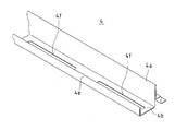
図4及び図5は、横桟4を示す斜視図及び断面図である。図4及び図5から明らかなように横桟4は、一枚の鋼板等を折り曲げたものであり、その中央に鋼板を折り曲げて重ねてなる境界壁4aが形成されている。この境界壁4aの一方側に、断面形状がコの字型のレール部4bが形成され、レール部4bの底部に長形孔4fが形成されている。レール部4bは、固定金具12の奥行きの長さと同一の幅を有し、このレール部4bに固定金具12を配置することができる。
4 and 5 are a perspective view and a cross-sectional view showing the
レール部4bの一方の側壁4cは、内側に折り曲げられて2重となり、その上端部が太陽電池モジュール5の枠部材7底面が載置される第1台座部4eとなっている。
One side wall 4c of the
また、横桟4の境界壁4aの他方側には、第2台座部4gが形成されている。第2台座部4gは、段状に形成されたものであり、第1台座部4eと同じ高さに設定されている。
A second pedestal portion 4g is formed on the other side of the boundary wall 4a of the
境界壁4aは、第1及び第2台座部4e、4gの上面に対して垂直に立っている。
The boundary wall 4a stands perpendicular to the upper surfaces of the first and
図6、図7、及び図8は、固定金具12を表側から見て示す斜視図、裏側から見て示す斜視図、及び側面図である。この固定金具12は、例えば奥行きが4cm、横が6cm、高さが6cm程度のサイズを有し、またその板厚が1.6mm程度である。
6, 7, and 8 are a perspective view showing the fixing
図6〜図8に示すように固定金具12は、底板12a、底板12aの両側を垂直に折り曲げてなる各側壁12b、及び底板12aの一辺を垂直に折り曲げてなる立設板(立設部)12cを有している。
As shown in FIGS. 6 to 8, the fixing
底板12aには、穿孔12dが形成されている。この底板12aの奥行の長さが横桟4のレール部4bの幅よりも僅かに短くされており、この底板12aが横桟4のレール部4bの内側に配置し得るようにされている。
各側壁12bの上端には、外側に折り曲げられた各受け部12eが形成されている。各側壁12b並びに各受け部12eは、立設板12cから離間している。また、各受け部12eの高さは、固定金具12の底板12aを横桟4のレール部4bに載せたときに横桟4の第1及び第2台座部4e、4gと同一高さもしくは僅かに低くなるように設定されている。
立設板12cの上端には、底板12a側に折り曲げられた第1留め部12fと、底板12aとは反対側に折り曲げられた第2留め部12gが形成されている。2つの第1留め部12fが立設板12cの上端両側に設けられ、また1つの第2留め部12gが立設板12cの上端中央に設けられ、2つの第1留め部12fと1つの第2留め部12gが交互に配置されている。
At the upper end of the standing
第1留め部12fは、立設板12cに対して直角に折り曲げられた押え部12hと、この押え部12hの先端側を斜め上方に折り曲げてなる呼込み部12iとを有している。また、第2留め部12gは、立設板12cに対して直角に折り曲げられている。尚、第1及び第2留め部12f、12gの個数を増減しても構わない。
The
また、立設板12cには、この立設板12cの背面側(底板12aとは反対側)に突出した2つの当たり部12jが形成されている。各当たり部12jは、立設板12cの高さ方向に長く相互に平行になるように形成されており、雨水が各当たり部12j間を流れ落ちるようにされている。また、各当たり部12jは、固定金具12の底板12aを横桟4のレール部4bに載せたときに横桟4の境界壁4aに当接し得る高さにある。
The standing
図9は、板ナット13を示す斜視図である。図9に示すように板ナット13は、主板13a、主板13aの一辺を垂直に折り曲げてなる第1当接部13b、及び主板13aに形成されたコの字型の切り込みの内側を起こしてなる第2当接部13cとを有している。
FIG. 9 is a perspective view showing the
第1及び第2当接部13b、13cの離間距離は、横桟4のレール部4bの外側幅よりも僅かに広くされており、板ナット13の主板13aを横桟4のレール部4bの外側底面に当接させたときに第1及び第2当接部13b、13c間に横桟4のレール部4bの外側が挟み込まれて、第1及び第2当接部13b、13cがレール部4bの外側壁面に当接する。
The separation distance between the first and
第1及び第2当接部13b、13cの略中央付近には、ネジ孔13dが形成されている。また、主板13aの端部には、穿孔13eが形成されている。
A
ここで、図3に示すように固定金具12の底板12aを横桟4のレール部4bに嵌め入れて配置し、固定金具12の立設板12cの背面の各当たり部12jを横桟4の境界壁4aに当接させる。また、板ナット13の主板13aを横桟4のレール部4bの外側底面に当接させ、板ナット13の第1及び第2当接部13b、13c間に横桟4のレール部4bの外側を挟み込む。この状態では、固定金具12の底板12aの穿孔12d、横桟4のレール部4bの長形孔4f、及び板ナット13の主板13aのネジ孔13dが重なり合い、ボルト21をワッシャ22、固定金具12の穿孔12d、及び横桟4の長形孔4fを介して板ナット13のネジ孔13dにねじ込むことができ、ボルト21を締め込むことにより固定金具12を横桟4のレール部4bに締結することができる。
Here, as shown in FIG. 3, the
また、ボルト21を締め込む前には、固定金具12の穿孔12dが横桟4の長形孔4fに重なる範囲で、固定金具12を横桟4のレール部4b内側で該横桟4の長手方向に移動させて、固定金具12の位置を調節することができる。
Before the
図10は、固定金具12を用いて、横桟4を挟んで配置された2枚の太陽電池モジュール5を該横桟4に固定した状態を示す断面図である。
FIG. 10 is a cross-sectional view showing a state in which two
図10に示すように固定金具12は、その底板12aを横桟4のレール部4bの内側底面に載せられ、その立設板12cの背面の各当たり部12jを横桟4の境界壁4aに当接させられている。また、板ナット13は、その主板13aを横桟4のレール部4bの外側底面に当接させられ、その第1及び第2当接部13b、13c間に横桟4のレール部4bの外側を挟み込んでいる。ボルト21は、ワッシャ22、固定金具12の穿孔12d、及び横桟4の長形孔4fを介して板ナット13のネジ孔13dにねじ込んで締め込まれ、固定金具12を横桟4のレール部4bに固定している。
As shown in FIG. 10, the fixing
一方の太陽電池モジュール5の枠部材7は、横桟4の第1台座部4eに載せられている。また、枠部材7の端部が固定金具12の各第1留め部12fの押え部12hの下側に押し込められて、各第1留め部12fの押え部12hにより枠部材7の端部上面が押えられ、枠部材7の端部が横桟4の第1台座部4eと各第1留め部12fの押え部12h間に挟みこまれて固定されている。また、枠部材7の端面が固定金具12の立設板12cに当接している。
The
この太陽電池モジュール5の枠部材7は、二点鎖線で示すように太陽電池モジュール5を傾斜させて、枠部材7の端部を固定金具12の各受け部12eに載せてスライドさせ、枠部材7の端部の下側角を固定金具12の各受け部12eと立設板12c間の空きスペースに移動させると共に、枠部材7の端部を各第1留め部12fの呼込み部12iから押え部12hへと挿入して押し込む。
The
各第1留め部12fの押え部12hの先端側に斜め上方に折り曲げられた呼込み部12iを形成していることから、傾斜した太陽電池モジュール5の枠部材7の端部を各第1留め部12fの呼込み部12iの下側に容易に入れることができ、引き続いて枠部材7の端部を各第1留め部12fの呼込み部12iから押え部12hへと容易に挿入して押し込むことができる。
Since the
また、固定金具12の各受け部12eと立設板12c間を離間させていることから、各第1留め部12fの下方が空き、枠部材7の端部を固定金具12の各受け部12eに載せてスライドさせると、傾斜した太陽電池モジュール5の枠部材7の端部の下側角が各受け部12eと立設板12c間に落ち込んで、枠部材7の端部上面を各第1留め部12fの押え部12hまで容易に押し込むことができる。
Further, since the receiving
こうして傾斜した太陽電池モジュール5の枠部材7の端部を各第1留め部12fの呼込み部12iから押え部12hへと挿入して押し込んだ後、太陽電池モジュール5の枠部材7を横桟4の第1台座部4eに載せると、各第1留め部12fの押え部12hにより枠部材7の端部上面が押えられ、枠部材7の端部が横桟4の第1台座部4eと各第1留め部12fの押え部12h間に挟みこまれて固定される。また、枠部材7の端面が固定金具12の立設板12cに当接する。
The end of the
尚、固定金具12の各受け部12eの高さが横桟4の第1台座部4eと同一高さである場合は、太陽電池モジュール5の枠部材7が横桟4の第1台座部4eと固定金具12の各受け部12eに載ることになる。
In addition, when the height of each receiving
また、図10に示すように他方の太陽電池モジュール5の枠部材7は、横桟4の第2台座部4gに載せられている。枠部材7の端部が固定金具12の第2留め部12gの下側に押し込められて、第2留め部12gにより枠部材7の端部上面が押えられ、枠部材7の端部が横桟4の第2台座部4gと第2留め部12g間に挟みこまれて固定されている。また、枠部材7の端面が横桟4の境界壁4aに当接している。
Further, as shown in FIG. 10, the
この太陽電池モジュール5の枠部材7は、二点鎖線で示すように太陽電池モジュール5の枠部材7の端部を横桟4の第2台座部4gの縁付近に載せてから、横桟4を太陽電池モジュール5の枠部材7に接近するように移動させて、枠部材7の端部を横桟4の第2台座部4gと第2留め部12g間に挿入して押し込むことにより固定される。また、枠部材7の端面が横桟4の境界壁4aに当接する。
The
次に、本実施形態の太陽電池モジュール用架台11により太陽電池モジュール5を屋根2上に取付けるための施工手順を説明する。
Next, a construction procedure for mounting the
まず、図1に示すように屋根2上に4本の縦桟3を離間させて相互に平行に固定配置する。屋根2に対する各縦桟3の固定は、周知の如何なる方法もしくは構造によってなされてもよい。
First, as shown in FIG. 1, four
引き続いて、各縦桟3上に、3本の横桟4を一定の間隔を開けて相互に平行に取付ける。図11に示すように縦桟3は、長細い主板3a、主板3aの両辺で折り曲げられた各側板3b、及び各側板3bの縁辺で折り曲げられた各鍔3cからなるハット型の断面形状を有しており、主板3aの2箇所に取付け孔3dが形成され、主板3aの3箇所に係合孔3eが形成されている。縦桟3の主板3aの各取付け孔3dは、縦桟3を屋根2に取付けるために用いられる。
Subsequently, three
縦桟3の主板3aの各係合孔3eには、図12に示すような取付け金具31が取付けられる。この取付け金具31は、その主板31aにネジ孔31bを形成し、その両側に各側板31cを設けて2重に折り曲げ、更にそれぞれの側板31cの中央から突出するT字型の支持片31dを設けたものである。
A fitting 31 as shown in FIG. 12 is attached to each
図13(a)、(b)に示すように、取付け金具31の一方の支持片31dを縦桟3のスリット3fに挿し込んで、この一方の支持片31dをスリット3fから係合孔3eへと移動させ、引き続いて取付け金具31の他方の支持片31dをスリット3fに挿し込んで、この他方の支持片31dもスリット3fから係合孔3eへと移動させ、各支持片31dのT字型の頭部を係合孔3eに引っ掛けて、取付け金具31を縦桟3の主板3aに取付ける。このとき、取付け金具31の各側板31cが縦桟3の各側板3bに対して垂直に配置される。
As shown in FIGS. 13A and 13B, one
次に、図14示すように縦桟3の係合孔3eに取付けられた取付け金具31の一対の支持片31d間に横桟4を配置し、取付け金具31の部位で、押え部材32を横桟4に重ね合わせ、ボルト33を押え部材32の孔及び横桟4の長形孔4fを通じて取付け金具31のネジ孔31bにねじ込んで、横桟4を縦桟3に仮止めする。
Next, as shown in FIG. 14, the
図1に示すように各縦桟3上に、3列の横桟4を一定の列間隔を開けて相互に並行に配置し、1列目の横桟4を支持する各取付け金具31のボルト33を締め付けて、1列目の横桟4を完全に固定し、2列目と3列目の各横桟4を仮止めする。
As shown in FIG. 1, three rows of
横桟4毎に、図3に示すように板ナット13及びボルト21を用いて、横桟4に固定金具12を固定する。
As shown in FIG. 3, the fixing
この後、図15(a)に示すように4枚の太陽電池モジュール5を横並びにして1列目の横桟4と2列目の横桟4間に挿入して配置する。
Thereafter, as shown in FIG. 15A, the four
そして、太陽電池モジュール5毎に、図15(b)に示すように太陽電池モジュール5の水流れ方向上流側一辺を持ち上げて、図15(c)に示すように太陽電池モジュール5の水流れ方向下流側一辺を1列目の横桟4に押し付ける。これにより、太陽電池モジュール5の水流れ方向下流側の端部(枠部材7の端部)が固定金具12の各第1留め部12fの呼込み部12iから押え部12hへと挿入されて押し込まれる。
And for every
更に、図15(d)に示すように太陽電池モジュール5の水流れ方向上流側一辺を降ろして、太陽電池モジュール5の水流れ方向下流側の端部を1列目の横桟4の第1台座部4eに載せ、太陽電池モジュール5の水流れ方向上流側の端部(枠部材7の端部)を2列目の横桟4の第2台座部4gの縁付近に載せる。このとき、1列目の横桟4に固定された固定金具12の各第1留め部12fの押え部12hにより太陽電池モジュール5の水流れ方向下流側の端部上面が押えられ、この下流側の端部が横桟4の第1台座部4eと固定金具12の各第1留め部12fの押え部12h間に挟みこまれて固定される。また、太陽電池モジュール5の水流れ方向下流側の端面が固定金具12の立設板12cに当接する。
Furthermore, as shown in FIG. 15 (d), the one side on the upstream side in the water flow direction of the
この後、2列目の横桟4を水流れ方向Aに移動させて太陽電池モジュール5の水流れ方向上流側一辺に押し付け、太陽電池モジュール5の水流れ方向上流側の端部を2列目の横桟4の第2台座部4gと該横桟4に固定された固定金具12の第2留め部12g間に挿入して押し込む。これにより、太陽電池モジュール5の水流れ方向上流側の端部が固定され、その上流側の端面が横桟4の境界壁4aに当接する。
After that, the second row of
そして、2列目の横桟4を支持する各取付け金具31のボルト33を締め付けて、2列目の横桟4を完全に固定する。
Then, the
同様の手順で、2列目の横桟4と3列目の横桟4間にも、4枚の太陽電池モジュール5を横並びにして固定する。
In the same procedure, the four
このように本実施形態の太陽電池モジュールシステム1では、横桟4を挟んで配置された2枚の太陽電池モジュール5が該横桟4に固定された固定金具12により固定される。これらの太陽電池モジュール5間に固定金具12の立設板12cが挟まれるが、この立設板12cが平板状のものであるから、各太陽電池モジュール5の隙間を狭くすることができる。また、固定金具12の第1及び第2留め部12f、12gは、太陽電池モジュール5の枠部材7の端部上面をそれぞれ押えるだけであるから、枠部材7の端部に係合部等を形成する必要がなく、枠部材7の端部の形状が複雑化することがない。このため、多様な太陽電池モジュールの適用が可能となり、固定金具12及び太陽電池モジュール用架台11の汎用性が広がる。また、枠部材7の端部の幅が広くならず、太陽電池発電システム1の設置面積に対する太陽光の受光面積の比率が減少することはない。
As described above, in the solar
更に、固定金具12の第1留め部12fは、押え部12hと、この押え部12hの先端側を斜め上方に折り曲げてなる呼込み部12iとを有することから、太陽電池モジュール5の枠部材7の端部を固定金具12の第1留め部12fの呼込み部12iに容易に挿入することができ、引き続いて枠部材7の端部を呼込み部12iから押え部12h下側へと容易に押し込むことができる。
Further, the
また、固定金具12の各受け部12eと立設板12c間を離間させていることから、各第1留め部12fの下方が空き、傾斜した太陽電池モジュール5の枠部材7の端部の下側角が各受け部12eと立設板12c間に落ち込んで、枠部材7の端部上面を各第1留め部12fの押え部12hまで容易に押し込むことができる。
In addition, since the receiving
更に、固定金具12の第1及び第2留め部12f、12gと横桟4の第1及び第2台座部4e、4gとの間に、隣り合う各太陽電池モジュール5の枠部材7の端部をそれぞれ挟み込むことにより、これらの太陽電池モジュール5を確実に固定することができる。
Furthermore, the edge part of the
以上、添付図面を参照しながら本発明の好適な実施形態について説明したが、本発明は係る例に限定されないことは言うまでもない。当業者であれば、特許請求の範囲に記載された範疇内において、各種の変更例または修正例に想到し得ることは明らかであり、それらについても当然に本発明の技術的範囲に属するものと解される。 As mentioned above, although preferred embodiment of this invention was described referring an accompanying drawing, it cannot be overemphasized that this invention is not limited to the example which concerns. It will be apparent to those skilled in the art that various changes and modifications can be made within the scope of the claims, and these are naturally within the technical scope of the present invention. It is understood.
例えば、太陽電池モジュールの代わりに、太陽熱発電に用いられる反射鏡パネル等を支持してもよい。これにより、太陽熱発電システムを構築することができる。 For example, instead of a solar cell module, a reflector panel or the like used for solar thermal power generation may be supported. Thereby, a solar thermal power generation system can be constructed.
1 太陽電池モジュールシステム
2 屋根
3 縦桟
4 横桟(桟)
4a 境界壁
4b レール部
4c 側壁
4e 第1台座部
4f 長形孔
4g 第2台座部
5 太陽電池モジュール
6 太陽電池パネル
7 枠部材
11 太陽電池モジュール用架台
12 固定金具(固定具)
12a 底板
12b 側壁
12c 立設板(立設部)
12d 穿孔
12e 受け部
12f 第1留め部
12g 第2留め部
12h 押え部
12i 呼込み部
12j 当たり部
13 板ナット
21 ボルト
22 ワッシャ
1 Solar
Claims (6)
隣り合う前記各太陽電池モジュールの端部に沿って配置される桟と、
前記桟に固定され、隣り合う前記各太陽電池モジュールの枠部材を共に固定する固定具とを備え、
前記固定具は、隣り合う前記各枠部材の間に挟まれる立設部と、前記立設部の上端で前記各枠部材の側にそれぞれ折り曲げられて、前記各枠部材上面をそれぞれ押える第1及び第2留め部と、前記第1留め部の折り曲げ側に設けられて隣り合う前記各枠部材の一方が載せられる受け部とを有し、
前記第1留め部は、枠部材上面を押える押え部と、前記押え部の先端側を斜め上方に折り曲げてなる呼込み部とを有し、
前記太陽電池モジュールは、前記枠部材が前記受け部と前記第1留め部の前記押え部との間に挿入されて固定され、
前記固定具の前記受け部と前記立設部との間には、前記太陽電池モジュールを傾斜させて前記枠部材を前記第1留め部と前記受け部との間に挿入した状態で前記枠部材の下側角が落ち込む空きスペースが設けられたことを特徴とする太陽電池モジュールの固定構造。 A solar cell module fixing structure that fixes a plurality of solar cell modules provided with a solar cell panel and a frame member that holds an edge of the solar cell panel ,
A bar disposed along an edge of each of the adjacent solar cell modules ;
Secured to said crosspiece, and a both fixtures for fixing the adjacent frame members of the solar cell modules,
The fixing tool is a first standing portion that is sandwiched between the adjacent frame members , and is bent to the side of each frame member at the upper end of the standing portion, and holds the upper surface of each frame member . And a second fastening part, and a receiving part on which one of the adjacent frame members provided on the folding side of the first fastening part is placed ,
The first fastening section, possess a pressing portion that presses the frame member upper surface, and said pressing portion of formed by bending a tip side obliquely upward invocation unit,
In the solar cell module, the frame member is inserted and fixed between the receiving portion and the pressing portion of the first fastening portion,
The frame member is inserted between the first fastening part and the receiving part by inclining the solar cell module between the receiving part and the standing part of the fixture. A structure for fixing a solar cell module, characterized in that an empty space is provided in which the lower corner of the solar cell falls .
前記桟は、隣り合う前記各枠部材が載置されるそれぞれの台座部を有し、
前記固定具の第1及び第2留め部と前記桟の各台座部との間に、隣り合う前記各枠部材をそれぞれ挟み込むことを特徴とする太陽電池モジュールの固定構造。 The solar cell module fixing structure according to claim 1,
The crosspiece has respective pedestal portions on which the adjacent frame members are placed,
The solar cell module fixing structure, wherein the adjacent frame members are sandwiched between the first and second fastening portions of the fixing tool and the pedestal portions of the crosspieces, respectively.
前記固定具の立設部は平板状であり、この平板状の立設部に前記枠部材が接することを特徴とする太陽電池モジュールの固定構造。 The solar cell module fixing structure according to claim 1 or 2 ,
It said standing portion of the fixture is plate-like, the fixing structure of the solar cell module, wherein the frame member is in contact with the plate-shaped standing portion.
隣り合う前記各太陽電池モジュールの端部に沿って配置される桟と、
前記桟に固定され、隣り合う前記各太陽電池モジュールの枠部材を共に固定する固定具とを備え、
前記固定具は、隣り合う前記各枠部材の間に挟まれる立設部と、前記立設部の上端で前記各枠部材の側にそれぞれ折り曲げられて、前記各枠部材上面をそれぞれ押える第1及び第2留め部と、前記第1留め部の折り曲げ側に設けられて隣り合う前記各枠部材の一方が載せられる受け部とを有し、
前記第1留め部は、前記受け部との間に挿入された枠部材を押える押え部と、前記押え部の先端側を斜め上方に折り曲げてなる呼込み部とを有し、
前記固定具の前記受け部と前記立設部との間には、前記太陽電池モジュールを傾斜させて前記枠部材を前記第1留め部と前記受け部との間に挿入した状態で前記枠部材の下側角が落ち込む空きスペースが設けられたことを特徴とする太陽電池モジュール用架台。 A solar cell module mount for fixing a plurality of solar cell modules provided with a solar cell panel and a frame member that holds an edge of the solar cell panel ,
A bar disposed along an edge of each of the adjacent solar cell modules;
Secured to said crosspiece, and a both fixtures for fixing the adjacent frame members of the solar cell modules,
The fixing tool is a first standing portion that is sandwiched between the adjacent frame members , and is bent to the side of each frame member at the upper end of the standing portion, and holds the upper surface of each frame member . And a second fastening part, and a receiving part on which one of the adjacent frame members provided on the folding side of the first fastening part is placed,
The first fastening section, possess a pressing portion for pressing the inserted frame member between, and the pressing portion of the formed by bending a tip side obliquely upward invocation portion with the receiving portion,
The frame member is inserted between the first fastening part and the receiving part by inclining the solar cell module between the receiving part and the standing part of the fixture. A stand for a solar cell module , characterized in that an empty space is provided in which the lower corner of the solar cell falls .
前記架台は、隣り合う前記各太陽電池モジュールの端部に沿って配置される桟と、前記桟に固定され、隣り合う前記各太陽電池モジュールの枠部材を共に固定する固定具とを備え、
前記固定具は、隣り合う前記各枠部材の間に挟まれる立設部と、前記立設部の上端で前記各枠部材の側にそれぞれ折り曲げられて、前記各枠部材上面をそれぞれ押える第1及び第2留め部と、前記第1留め部の折り曲げ側に設けられて隣り合う前記各枠部材の一方が載せられる受け部とを有し、
前記第1留め部は、前記受け部との間に挿入された枠部材上面を押える押え部と、前記押え部の先端側を斜め上方に折り曲げてなる呼込み部とを有し、
前記固定具の前記受け部と前記立設部との間には、前記太陽電池モジュールを傾斜させて前記枠部材を前記第1留め部と前記受け部との間に挿入した状態で前記枠部材の下側角が落ち込む空きスペースが設けられており、
前列及び後列の桟を相互に平行に配置する工程と、
前記前列及び後列の桟にそれぞれの固定具を固定する工程と、
前記太陽電池モジュールの一方の端部の枠部材を前記前列の桟に固定された固定具の受け部に載せる工程と、
前記太陽電池モジュールを傾斜させて前記枠部材を前記第1留め部と前記受け部との間に挿入し、前記空きスペースに前記枠部材の下側角を落ち込ませ、前記枠部材を前記第1留め部の呼込み部から押え部下側へ挿入する工程と、
前記太陽電池モジュールの傾斜を元に戻して、前記枠部材が前記受け部に載せられると共に前記第1留め部の押さえ部により押さえられた状態とする工程と、
前記後列の桟を前記前列の桟側に移動させて、前記太陽電池モジュールの他方の端部の枠部材を前記後列の桟の固定具の第2留め部下側に挿入し、該第2留め部により前記太陽電池モジュールの他方の端部の枠部材を押さえ、前記太陽電池モジュールを固定する工程とを含むことを特徴とする太陽電池モジュールの施工方法。 A solar cell module construction method for installing a plurality of solar cell modules including a solar cell panel and a frame member holding an edge of the solar cell panel using a mount,
The gantry includes a bar disposed along an end of each adjacent solar cell module, and a fixture that is fixed to the bar and fixes the frame members of the adjacent solar cell modules together.
The fixing tool is a first standing portion that is sandwiched between the adjacent frame members, and is bent to the side of each frame member at the upper end of the standing portion, and holds the upper surface of each frame member. And a second fastening part, and a receiving part on which one of the adjacent frame members provided on the folding side of the first fastening part is placed,
The first fastening part has a presser part that presses the upper surface of the frame member inserted between the receiving part and a call-in part formed by bending the front end side of the presser part obliquely upward,
The frame member is inserted between the first fastening part and the receiving part by inclining the solar cell module between the receiving part and the standing part of the fixture. There is an empty space where the lower corner of the
Arranging the front row and back row bars parallel to each other;
Fixing each fixture to the front row and rear row bars;
Placing a frame member at one end of the solar cell module on a receiving portion of a fixture fixed to the front row of bars;
The solar cell module is inclined and the frame member is inserted between the first fastening portion and the receiving portion, and a lower corner of the frame member is dropped into the empty space, and the frame member is moved to the first portion. A process of inserting from the calling part of the fastening part to the lower side of the presser part;
The step of returning the inclination of the solar cell module to the original state and placing the frame member on the receiving portion and being pressed by the pressing portion of the first fastening portion;
By moving the rear row of bars to桟側of the front row, and insert the frame member at the other end of the solar cell module to the second fastening part lower fixture of the rear row of bars, the second fastening portion Pressing the frame member at the other end of the solar cell module and fixing the solar cell module.
Priority Applications (1)
| Application Number | Priority Date | Filing Date | Title |
|---|---|---|---|
| JP2010015748A JP5388880B2 (en) | 2010-01-27 | 2010-01-27 | Solar cell module fixing structure, solar cell module mount, solar cell module construction method, and solar cell power generation system |
Applications Claiming Priority (1)
| Application Number | Priority Date | Filing Date | Title |
|---|---|---|---|
| JP2010015748A JP5388880B2 (en) | 2010-01-27 | 2010-01-27 | Solar cell module fixing structure, solar cell module mount, solar cell module construction method, and solar cell power generation system |
Publications (2)
| Publication Number | Publication Date |
|---|---|
| JP2011153465A JP2011153465A (en) | 2011-08-11 |
| JP5388880B2 true JP5388880B2 (en) | 2014-01-15 |
Family
ID=44539621
Family Applications (1)
| Application Number | Title | Priority Date | Filing Date |
|---|---|---|---|
| JP2010015748A Active JP5388880B2 (en) | 2010-01-27 | 2010-01-27 | Solar cell module fixing structure, solar cell module mount, solar cell module construction method, and solar cell power generation system |
Country Status (1)
| Country | Link |
|---|---|
| JP (1) | JP5388880B2 (en) |
Families Citing this family (7)
| Publication number | Priority date | Publication date | Assignee | Title |
|---|---|---|---|---|
| JP5780501B2 (en) * | 2011-11-09 | 2015-09-16 | 元旦ビューティ工業株式会社 | Solar cell module installation structure and installation method |
| JP5943322B2 (en) * | 2012-03-19 | 2016-07-05 | 日立アプライアンス株式会社 | Solar cell module fixing structure and solar power generation system |
| US20150122333A1 (en) | 2012-05-11 | 2015-05-07 | Kyocera Corporation | Photovoltaic system |
| JP6021579B2 (en) * | 2012-10-19 | 2016-11-09 | シャープ株式会社 | Solar cell module support structure and solar cell module installation method |
| JP6406827B2 (en) * | 2014-01-14 | 2018-10-17 | 株式会社Nttファシリティーズ | Solar panel mounting bracket, solar panel mount, and solar panel construction method |
| US10224864B2 (en) | 2015-04-30 | 2019-03-05 | Solar Frontier K.K. | Solar cell module mounting device |
| JP6189367B2 (en) * | 2015-06-18 | 2017-08-30 | ニイガタ製販株式会社 | Solar panel mounting bracket |
Family Cites Families (2)
| Publication number | Priority date | Publication date | Assignee | Title |
|---|---|---|---|---|
| JP3685880B2 (en) * | 1996-08-01 | 2005-08-24 | ミサワホーム株式会社 | Solar panel fixture and roof structure |
| JP3907668B2 (en) * | 2005-04-07 | 2007-04-18 | シャープ株式会社 | Mounting structure of solar cell module |
-
2010
- 2010-01-27 JP JP2010015748A patent/JP5388880B2/en active Active
Also Published As
| Publication number | Publication date |
|---|---|
| JP2011153465A (en) | 2011-08-11 |
Similar Documents
| Publication | Publication Date | Title |
|---|---|---|
| JP4688951B1 (en) | Structure installation stand, structure installation support, and solar power generation system | |
| JP5388880B2 (en) | Solar cell module fixing structure, solar cell module mount, solar cell module construction method, and solar cell power generation system | |
| JP4879336B2 (en) | Solar cell module support structure, method of constructing the support structure, and photovoltaic power generation system using the support structure | |
| JP3907668B2 (en) | Mounting structure of solar cell module | |
| JP4202401B1 (en) | Structure installation stand, its assembling method, solar cell module, and construction structure using structure installation stand | |
| JP2011106188A (en) | Roof | |
| KR102054871B1 (en) | Mounting module of Solar panels installed pitched-roof | |
| JP2013044114A (en) | Fixing structure for solar cell module | |
| JP3869292B2 (en) | Support bracket for solar panel mounting | |
| JP5213977B2 (en) | Solar cell module mount, construction method thereof, and solar power generation system including the same | |
| JP5388311B2 (en) | Solar cell module support structure, solar power generation system using the support structure, and solar cell module installation method | |
| JP5463331B2 (en) | Solar cell module support structure, method of constructing the support structure, and photovoltaic power generation system using the support structure | |
| JP6334941B2 (en) | Structure and method for supporting and fixing a planar article on a roof | |
| JP5916096B2 (en) | Installation structure of solar energy utilization equipment | |
| JP2019073899A (en) | Photovoltaic power generation device | |
| JP3934453B2 (en) | Roof structure with solar panel | |
| JP6021579B2 (en) | Solar cell module support structure and solar cell module installation method | |
| JP5405631B2 (en) | Solar cell module installation structure, solar cell module installation method, and solar power generation system | |
| JP2017066806A (en) | Installation structure, installation method of solar cell module, and photovoltaic power generation system using installation structure of the same | |
| JP5965376B2 (en) | Solar cell module support structure and solar power generation system using the support structure | |
| JP6189367B2 (en) | Solar panel mounting bracket | |
| JP2008088685A (en) | Solar cell module | |
| JP7304664B1 (en) | Solar panel mounting frame, solar panel system and solar panel mounting method | |
| KR101124440B1 (en) | Installation method of solar sell module | |
| JP5923078B2 (en) | Solar cell module installation structure, solar cell module installation method, and solar power generation system |
Legal Events
| Date | Code | Title | Description |
|---|---|---|---|
| A621 | Written request for application examination |
Free format text: JAPANESE INTERMEDIATE CODE: A621 Effective date: 20120223 |
|
| A977 | Report on retrieval |
Free format text: JAPANESE INTERMEDIATE CODE: A971007 Effective date: 20130130 |
|
| A131 | Notification of reasons for refusal |
Free format text: JAPANESE INTERMEDIATE CODE: A131 Effective date: 20130205 |
|
| A521 | Written amendment |
Free format text: JAPANESE INTERMEDIATE CODE: A523 Effective date: 20130405 |
|
| TRDD | Decision of grant or rejection written | ||
| A01 | Written decision to grant a patent or to grant a registration (utility model) |
Free format text: JAPANESE INTERMEDIATE CODE: A01 Effective date: 20130917 |
|
| A61 | First payment of annual fees (during grant procedure) |
Free format text: JAPANESE INTERMEDIATE CODE: A61 Effective date: 20131008 |
|
| R150 | Certificate of patent or registration of utility model |
Ref document number: 5388880 Country of ref document: JP Free format text: JAPANESE INTERMEDIATE CODE: R150 Free format text: JAPANESE INTERMEDIATE CODE: R150 |