JP5381380B2 - Image processing apparatus, image forming system, and program - Google Patents
Image processing apparatus, image forming system, and program Download PDFInfo
- Publication number
- JP5381380B2 JP5381380B2 JP2009145646A JP2009145646A JP5381380B2 JP 5381380 B2 JP5381380 B2 JP 5381380B2 JP 2009145646 A JP2009145646 A JP 2009145646A JP 2009145646 A JP2009145646 A JP 2009145646A JP 5381380 B2 JP5381380 B2 JP 5381380B2
- Authority
- JP
- Japan
- Prior art keywords
- color
- adjustment
- group
- unit
- correction
- Prior art date
- Legal status (The legal status is an assumption and is not a legal conclusion. Google has not performed a legal analysis and makes no representation as to the accuracy of the status listed.)
- Expired - Fee Related
Links
- 238000012545 processing Methods 0.000 title claims description 121
- 238000006243 chemical reaction Methods 0.000 claims description 127
- 238000005259 measurement Methods 0.000 claims description 127
- 238000000926 separation method Methods 0.000 claims description 94
- 238000012937 correction Methods 0.000 claims description 73
- 239000003086 colorant Substances 0.000 claims description 22
- 238000004737 colorimetric analysis Methods 0.000 claims description 16
- 238000000354 decomposition reaction Methods 0.000 claims description 2
- 238000004364 calculation method Methods 0.000 description 61
- 238000013500 data storage Methods 0.000 description 37
- 238000000034 method Methods 0.000 description 33
- 230000006870 function Effects 0.000 description 30
- 238000010586 diagram Methods 0.000 description 13
- 238000009877 rendering Methods 0.000 description 7
- 238000004458 analytical method Methods 0.000 description 6
- 241000533901 Narcissus papyraceus Species 0.000 description 4
- 230000015654 memory Effects 0.000 description 4
- 238000013528 artificial neural network Methods 0.000 description 3
- 238000000611 regression analysis Methods 0.000 description 3
- 238000004891 communication Methods 0.000 description 2
- 230000000694 effects Effects 0.000 description 2
- 239000000463 material Substances 0.000 description 2
- 230000004044 response Effects 0.000 description 2
- 230000005540 biological transmission Effects 0.000 description 1
- 239000000284 extract Substances 0.000 description 1
- 230000002123 temporal effect Effects 0.000 description 1
- 230000003936 working memory Effects 0.000 description 1
Images


Classifications
-
- H—ELECTRICITY
- H04—ELECTRIC COMMUNICATION TECHNIQUE
- H04N—PICTORIAL COMMUNICATION, e.g. TELEVISION
- H04N1/00—Scanning, transmission or reproduction of documents or the like, e.g. facsimile transmission; Details thereof
- H04N1/46—Colour picture communication systems
- H04N1/56—Processing of colour picture signals
- H04N1/60—Colour correction or control
- H04N1/603—Colour correction or control controlled by characteristics of the picture signal generator or the picture reproducer
- H04N1/6033—Colour correction or control controlled by characteristics of the picture signal generator or the picture reproducer using test pattern analysis
-
- G—PHYSICS
- G01—MEASURING; TESTING
- G01J—MEASUREMENT OF INTENSITY, VELOCITY, SPECTRAL CONTENT, POLARISATION, PHASE OR PULSE CHARACTERISTICS OF INFRARED, VISIBLE OR ULTRAVIOLET LIGHT; COLORIMETRY; RADIATION PYROMETRY
- G01J3/00—Spectrometry; Spectrophotometry; Monochromators; Measuring colours
- G01J3/46—Measurement of colour; Colour measuring devices, e.g. colorimeters
- G01J3/462—Computing operations in or between colour spaces; Colour management systems
Landscapes
- Physics & Mathematics (AREA)
- Spectroscopy & Molecular Physics (AREA)
- Engineering & Computer Science (AREA)
- General Physics & Mathematics (AREA)
- Signal Processing (AREA)
- Multimedia (AREA)
- Mathematical Physics (AREA)
- Theoretical Computer Science (AREA)
- Facsimile Image Signal Circuits (AREA)
- Image Processing (AREA)
- Color Image Communication Systems (AREA)
- Accessory Devices And Overall Control Thereof (AREA)
- Color, Gradation (AREA)
Description
本発明は、画像処理装置、画像形成システム、およびプログラムに関する。 The present invention relates to an image processing apparatus, an image forming system, and a program.
カラープリンタ等の画像形成装置においては、一般に、入力される画像信号の色空間(入力色空間)と画像形成処理に用いる色空間(出力色空間)とが異なるため、色空間を変換する色変換処理が行われる。この色変換処理は、通常、入力色空間の色と出力色空間の色とを予め対応付けておき、その対応関係(テーブル)に基づいて行われる。この対応関係は、例えば経時的な要因等によって変動することがある。
例えば、特許文献1には、一定精度以上の色修正を行うために必要な最低測色点数に対応するパッチが測色順の早い位置に配置されたカラーパッチを印刷し、このカラーパッチのうち、少なくとも最低測色点数に対応するパッチを測色することによって色修正テーブルの作成に必要な色彩値を取得し、取得した色彩値と標準印刷結果の色彩値である標準値とを対比し、この対比結果に基づいて任意の階調値のカラー画像データに対応する標準印刷結果と同等の印刷結果を印刷装置によって得られるようにカラー画像データを修正する色修正テーブルを作成する技術が記載されている。
In an image forming apparatus such as a color printer, since the color space (input color space) of an input image signal is generally different from the color space (output color space) used for image forming processing, color conversion for converting the color space is performed. Processing is performed. This color conversion processing is normally performed based on the correspondence (table) in which the colors in the input color space and the colors in the output color space are associated in advance. This correspondence may vary depending on factors over time, for example.
For example, Patent Document 1 prints a color patch in which patches corresponding to the minimum number of colorimetric points necessary for performing color correction with a certain accuracy or higher are arranged at an earlier position in the colorimetric order. The color value necessary for creating the color correction table is obtained by measuring the patches corresponding to at least the minimum number of colorimetric points, and the obtained color value is compared with the standard value which is the color value of the standard print result. Based on this comparison result, a technique for creating a color correction table for correcting color image data so as to obtain a printing result equivalent to a standard printing result corresponding to color image data of an arbitrary gradation value by a printing apparatus is described. ing.
ここで一般に、入力色空間の画像信号と出力色空間の画像信号との対応関係に生じる例えば経時的な要因等による変動は、大きい場合もあれば小さい場合もある。そのため、かかる対応関係に関し色見本の測色等の作業を伴う調整処理を一律に行うとすると、例えば対応関係に生じた変動量が小さい場合には不必要に精密な調整が行われることとなり、調整処理に要する時間が無駄となる場合がある。
本発明は、入力色空間の画像信号と出力色空間の画像信号との対応関係に施す調整をより効率的に実施することを目的とする。
Here, in general, a variation caused by, for example, a temporal factor or the like occurring in the correspondence relationship between the image signal in the input color space and the image signal in the output color space may be large or small. For this reason, assuming that the adjustment process involving the color measurement of the color sample is uniformly performed with respect to such a correspondence relationship, for example, if the amount of change occurring in the correspondence relationship is small, an unnecessarily precise adjustment is performed. The time required for the adjustment process may be wasted.
SUMMARY OF THE INVENTION An object of the present invention is to more efficiently perform adjustments made to the correspondence between an input color space image signal and an output color space image signal.
請求項1に記載の発明は、第1の色空間の画像信号と第2色空間の画像信号との対応関係を定める色変換特性を用いて、当該第1の色空間の画像信号を当該第2色空間の画像信号に色変換する色変換手段と、前記色変換手段にて色変換された前記第2色空間の画像信号を、前記色変換特性の変動に応じて調整する調整手段と、前記調整手段にて前記第2色空間の画像信号を調整する際に使用される調整用変換係数群を補正する補正手段と、前記調整用変換係数群を作成するために測色される第1の色見本群よりも色見本数が少なく構成された第2の色見本群に関する測色結果により、前記補正手段での前記調整用変換係数群の補正が必要か否かを判定する判定手段と、を備え、前記判定手段は、前記第2の色見本群に関する測色結果により前記調整用変換係数群の補正が必要であると判定した場合に、当該調整用変換係数群全体を新たに作成し直すための色見本からなる前記第1の色見本群を用いて補正を行うか、または1次元ルックアップテーブルを算出するための色見本からなる第3の色見本群を用いて当該調整用変換係数群の一部を新たに作成し直す補正を行うかをさらに判定することを特徴とする画像処理装置である。 According to the first aspect of the present invention, the image signal in the first color space is converted into the first color space using color conversion characteristics that define the correspondence between the image signal in the first color space and the image signal in the second color space. Color conversion means for performing color conversion into an image signal in a two-color space; and adjustment means for adjusting the image signal in the second color space that has been color-converted by the color conversion means in accordance with variations in the color conversion characteristics; Correction means for correcting an adjustment conversion coefficient group used when adjusting the image signal in the second color space by the adjustment means, and first colorimetric measurement for creating the adjustment conversion coefficient group. Determining means for determining whether or not the correction conversion coefficient group needs to be corrected by the correcting means based on a colorimetric result relating to the second color sample group configured to have a smaller number of color samples than the color sample group; , And the determination means uses a colorimetric result relating to the second color sample group. Whether correction is performed using the first color swatch group consisting of color swatches for re-creating the entire adjustment transform coefficient group when it is determined that correction of the adjustment conversion coefficient group is necessary Or further determining whether or not to perform a correction for re-creating a part of the adjustment conversion coefficient group by using a third color sample group including color samples for calculating a one-dimensional lookup table. An image processing apparatus is characterized.
請求項2に記載の発明は、前記第1の色見本群は、多次元ルックアップテーブルを算出するための色見本からなることを特徴とする請求項1記載の画像処理装置である。
請求項3に記載の発明は、前記補正手段は、前記判定手段で前記調整用変換係数群の補正が必要であると判定し、さらに前記第1の色見本群または前記第3の色見本群を用いて補正を行うかを判定した結果に応じて、当該第1の色見本群を用いて当該調整用変換係数群全体を新たに作成し直す補正を行うか、または当該第3の色見本群を用いて当該調整用変換係数群の一部を新たに作成し直す補正を行い、補正された当該調整用変換係数群により当該補正手段にて使用される当該調整用変換係数群を更新することを特徴とする請求項1または2記載の画像処理装置である。
請求項4に記載の発明は、前記判定手段での前記調整用変換係数群の補正に関する判定結果に応じて、前記第2の色見本群以外を測色する必要のないことを使用者に通知するか、または、前記第1の色見本群および前記第3の色見本群の何れか一または双方を測色する必要があることを使用者に通知する通知手段をさらに備えたことを特徴とする請求項1記載の画像処理装置である。
請求項5に記載の発明は、前記色変換手段にて色変換された前記第2色空間の画像信号を構成する一または複数の色成分、または前記調整手段にて調整された前記第2色空間の画像信号を構成する一または複数の色成分を、第1色成分と当該第1色成分よりも明度および彩度の何れか一または双方が低い第2色成分とに分解する色分解手段をさらに備え、前記判定手段は、前記第2の色見本群に関する測色結果により、前記色分解手段にて使用される前記色成分を前記第1色成分と前記第2色成分とに分解する際の当該第1色成分の値と当該第2色成分の値とを定める分解係数群の補正が必要か否かを判定することを特徴とする請求項1記載の画像処理装置である。
A second aspect of the present invention is the image processing apparatus according to the first aspect, wherein the first color sample group includes color samples for calculating a multidimensional lookup table .
According to a third aspect of the present invention, the correction means determines that the adjustment conversion coefficient group needs to be corrected by the determination means, and further the first color sample group or the third color sample group. In accordance with the result of determining whether correction is performed using the first color sample group, correction is performed to newly create the entire adjustment coefficient group for adjustment using the first color sample group, or the third color sample is performed. Correction is performed by newly creating a part of the adjustment conversion coefficient group using the group, and the adjustment conversion coefficient group used in the correction unit is updated with the corrected adjustment conversion coefficient group. The image processing apparatus according to
The invention according to claim 4 notifies the user that it is not necessary to measure colors other than the second color sample group according to the determination result relating to the correction of the adjustment conversion coefficient group by the determination means. either or, and further comprising a notification means for notifying the user that it is necessary to colorimetry either one or both of the first color sample group and the third color sample group The image processing apparatus according to claim 1.
According to a fifth aspect of the present invention, one or a plurality of color components constituting the image signal of the second color space color-converted by the color conversion unit, or the second color adjusted by the adjustment unit Color separation means for separating one or a plurality of color components constituting an image signal in space into a first color component and a second color component having either one or both of lightness and saturation lower than the first color component And the determination means separates the color component used in the color separation means into the first color component and the second color component based on a color measurement result relating to the second color sample group. The image processing apparatus according to claim 1, wherein it is determined whether correction of a decomposition coefficient group that determines the value of the first color component and the value of the second color component is necessary.
請求項6に記載の発明は、第1の色空間の画像信号に画像処理を行って第2色空間の画像信号を生成する画像処理手段と、前記画像処理手段により生成された前記第2色空間の画像信号に基づいて記録媒体上に画像を形成する画像形成手段とを有し、前記画像処理手段は、前記第1の色空間の画像信号と前記第2色空間の画像信号との対応関係を定めた色変換特性を用いて、当該第1の色空間の画像信号を当該第2色空間の画像信号に色変換する色変換手段と、前記色変換手段にて色変換された前記第2色空間の画像信号を、前記色変換特性の変動に応じて調整する調整手段と、前記調整手段にて前記第2色空間の画像信号を調整する際に使用される調整用変換係数群を補正する補正手段と、前記調整用変換係数群を作成するために測色される第1の色見本群よりも色見本数が少なく構成された第2の色見本群に関する測色結果により、前記補正手段での前記調整用変換係数群の補正が必要か否かを判定する判定手段と、を備え、前記画像処理手段の前記判定手段は、前記第2の色見本群に関する測色結果により前記調整用変換係数群の補正が必要であると判定した場合に、当該調整用変換係数群全体を新たに作成し直すための色見本からなる前記第1の色見本群を用いて補正を行うか、または1次元ルックアップテーブルを算出するための色見本からなる第3の色見本群を用いて当該調整用変換係数群の一部を新たに作成し直す補正を行うかをさらに判定することを特徴とする画像形成システムである。 According to a sixth aspect of the present invention, there is provided image processing means for generating an image signal in the second color space by performing image processing on the image signal in the first color space, and the second color generated by the image processing means. Image forming means for forming an image on a recording medium based on the image signal of the space, and the image processing means corresponds to the image signal of the first color space and the image signal of the second color space Color conversion means for color-converting the image signal of the first color space into the image signal of the second color space using the color conversion characteristics that define the relationship, and the first color converted by the color conversion means An adjustment unit that adjusts an image signal in a two-color space according to a change in the color conversion characteristics; and an adjustment conversion coefficient group that is used when the adjustment unit adjusts the image signal in the second color space. Correction means for correcting and colorimetric measurement are performed to create the adjustment conversion coefficient group. Determination of whether or not the correction conversion coefficient group needs to be corrected by the correction unit based on a color measurement result related to the second color sample group configured to have a smaller number of color samples than the first color sample group And when the determination means of the image processing means determines that the adjustment conversion coefficient group needs to be corrected based on a color measurement result related to the second color sample group, the adjustment conversion Correction is performed using the first color sample group consisting of color samples for newly recreating the entire coefficient group, or a third color sample consisting of color samples for calculating a one-dimensional lookup table It is an image forming system characterized in that it is further determined whether correction is performed by newly creating a part of the adjustment conversion coefficient group using the group .
請求項7に記載の発明は、前記第1の色見本群は、多次元ルックアップテーブルを算出するための色見本からなることを特徴とする請求項6記載の画像形成システムである。
請求項8に記載の発明は、前記画像処理手段の前記補正手段は、前記判定手段で前記調整用変換係数群の補正が必要であると判定し、さらに前記第1の色見本群または前記第3の色見本群を用いて補正を行うかを判定した結果に応じて、当該第1の色見本群を用いて当該調整用変換係数群全体を新たに作成し直す補正を行うか、または当該第3の色見本群を用いて当該調整用変換係数群の一部を新たに作成し直す補正を行い、補正された当該調整用変換係数群により当該補正手段にて使用される当該調整用変換係数群を更新することを特徴とする請求項6または7記載の画像形成システムである。
請求項9に記載の発明は、前記画像処理手段の前記調整手段にて前記第2色空間の画像信号を調整するために使用される調整用変換係数群を補正する旨の使用者からの指示入力を受け付ける受付手段をさらに備え、前記画像形成手段は、前記受付手段にて前記指示入力を受け付けることにより、記録媒体上に前記第2の色見本群を含む画像を形成することを特徴とする請求項6記載の画像形成システムである。
請求項10に記載の発明は、前記画像形成手段は、前記第2色空間の1次色各々を予め定めた間隔毎の色座標値で形成した前記第2の色見本群を含む画像を形成することを特徴とする請求項9記載の画像形成システムである。
請求項11に記載の発明は、前記判定手段での前記調整用変換係数群の補正に関する判定結果に応じて、前記第2の色見本群以外を測色する必要のないことを使用者に通知するか、または、前記第1の色見本群および前記第3の色見本群の何れか一または双方を測色する必要があることを使用者に通知する通知手段をさらに備えたことを特徴とする請求項6記載の画像形成システムである。
A seventh aspect of the present invention is the image forming system according to the sixth aspect, wherein the first color sample group includes color samples for calculating a multidimensional lookup table .
In the invention according to claim 8, the correction means of the image processing means determines that the adjustment conversion coefficient group needs to be corrected by the determination means, and further, the first color sample group or the first color sample group. Depending on the result of determining whether to perform correction using the three color sample groups, correction is performed to newly create the entire conversion coefficient group for adjustment using the first color sample group, or Using the third color sample group, correction is performed to newly create a part of the adjustment conversion coefficient group, and the adjustment conversion is used in the correction means by the corrected adjustment conversion coefficient group. a claim 6 or 7, wherein the image forming system and updates the coefficient group.
According to a ninth aspect of the present invention, there is provided an instruction from a user to correct an adjustment conversion coefficient group used for adjusting an image signal in the second color space by the adjusting unit of the image processing unit. The image forming unit further includes an accepting unit that accepts an input, and the image forming unit forms an image including the second color sample group on a recording medium by accepting the instruction input by the accepting unit. The image forming system according to claim 6.
According to a tenth aspect of the present invention, the image forming unit forms an image including the second color sample group in which each primary color of the second color space is formed with color coordinate values at predetermined intervals. The image forming system according to claim 9.
The invention according to
請求項12に記載の発明は、コンピュータに、第1の色空間の画像信号と第2色空間の画像信号との対応関係を定めた色変換特性によって変換された当該第2色空間の画像信号を当該色変換特性の変動に応じて調整する際に使用する調整用変換係数群を補正する機能と、前記調整用変換係数群を作成するために測色される第1の色見本群よりも色見本数が少なく構成された第2の色見本群に関する測色データを取得する機能と、目標とする前記色変換特性を設定する前記第1の色空間の画像信号と前記第2色空間の画像信号との組み合わせからなる目標データ群を記憶する記憶手段から、当該目標データ群を取得する機能と、取得した前記測色データと前記目標データ群とを比較し、当該測色データと当該目標データ群との比較結果に応じて前記調整用変換係数群に関する補正が必要か否かを判定する機能と、を実現させ、前記判定する機能は、前記調整用変換係数群の補正が必要であると判定した場合に、当該調整用変換係数群全体を新たに作成し直すための色見本からなる前記第1の色見本群を用いて補正を行うか、または1次元ルックアップテーブルを算出するための色見本からなる第3の色見本群を用いて当該調整用変換係数群の一部を新たに作成し直す補正を行うかをさらに判定することを特徴とするプログラムである。
請求項13に記載の発明は、前記第1の色見本群は、多次元ルックアップテーブルを算出するための色見本からなることを特徴とする請求項12記載のプログラムである。
According to a twelfth aspect of the present invention, an image signal of the second color space converted by a computer according to a color conversion characteristic that defines a correspondence relationship between the image signal of the first color space and the image signal of the second color space. Than the first color sample group that is color-measured to create the adjustment conversion coefficient group and the function of correcting the adjustment conversion coefficient group used when adjusting the color conversion characteristics according to the change in the color conversion characteristics A function of acquiring colorimetric data relating to a second color sample group configured with a small number of color samples, an image signal of the first color space for setting the target color conversion characteristics, and the second color space The function of acquiring the target data group from the storage means for storing the target data group consisting of a combination with the image signal, the acquired colorimetric data and the target data group are compared, and the colorimetric data and the target data group are compared. Depending on the comparison result with the data group Serial and function of determining whether it is necessary to correct regarding the adjustment conversion coefficient set, to realize the function of determining, when it is determined that it is necessary to correct the adjustment transform coefficient group, for the adjustment Correction is performed using the first color swatch group consisting of color swatches for newly recreating the entire conversion coefficient group, or a third color consisting of color swatches for calculating a one-dimensional lookup table It is a program characterized by further determining whether or not to perform correction for newly creating a part of the adjustment conversion coefficient group by using a sample group .
The invention according to
請求項1の発明によれば、本発明を採用しない場合に比較して、入力色空間の画像信号と出力色空間の画像信号との対応関係に施す調整をより効率的に実施することができる。
請求項2の発明によれば、本発明を採用しない場合に比較して、色見本群に関する測色数がより少なくなり、使用者の測色の手間を低減することができる。
請求項3の発明によれば、本発明を採用しない場合に比較して、第2の色見本群に関する測色結果に応じた調整用変換係数群を設定でき、調整用変換係数群に関する不要に精度の高い調整を行うことを抑制することができる。
請求項4の発明によれば、本発明を採用しない場合に比較して、使用者が不必要な色見本の測色を行うことを抑制することができる。
請求項5の発明によれば、本発明を採用しない場合に比較して、4色以上の多色により色再現する場合においても、色見本群に関する測色数をより少なくし、使用者の測色の手間を低減することができる。
According to the first aspect of the present invention, compared with the case where the present invention is not adopted, it is possible to more efficiently carry out the adjustment to be performed on the correspondence relationship between the image signal in the input color space and the image signal in the output color space. .
According to the second aspect of the present invention, compared to the case where the present invention is not adopted, the number of colorimetric measurements related to the color sample group is reduced, and the user's labor for colorimetry can be reduced.
According to the third aspect of the present invention, compared to the case where the present invention is not adopted, the adjustment conversion coefficient group can be set according to the color measurement result related to the second color sample group, and the adjustment conversion coefficient group is unnecessary. It is possible to suppress the adjustment with high accuracy.
According to the fourth aspect of the present invention, it is possible to prevent the user from performing unnecessary color measurement of the color sample as compared with the case where the present invention is not adopted.
According to the invention of
請求項6の発明によれば、本発明を採用しない場合に比較して、入力色空間の画像信号と出力色空間の画像信号との対応関係に施す調整をより効率的に実施することができる。
請求項7の発明によれば、本発明を採用しない場合に比較して、色見本群に関する測色数をより少なくし、使用者の測色の手間を低減することができる。
請求項8の発明によれば、本発明を採用しない場合に比較して、第2の色見本群に関する測色結果に応じた調整用変換係数群を設定でき、調整用変換係数群に関する不要に精度の高い調整を行うことを抑制することができる。
請求項9の発明によれば、本発明を採用しない場合に比較して、使用者が測色する色見本を調整用変換係数群の補正に関する判定に必要なものだけとし、使用者の測色の手間を低減することができる。
請求項10の発明によれば、本発明を採用しない場合に比較して、画像形成手段が印刷する色見本を、調整用変換係数群の補正に関する判定に必要なものに限定することができる。
請求項11の発明によれば、本発明を採用しない場合に比較して、使用者が不必要な色見本の測色を行うことを抑制することができる。
According to the sixth aspect of the present invention, it is possible to more efficiently carry out the adjustment to be made to the correspondence relationship between the image signal in the input color space and the image signal in the output color space, as compared with the case where the present invention is not adopted. .
According to the seventh aspect of the present invention, compared to the case where the present invention is not adopted, the number of colorimetric measurements related to the color sample group can be reduced, and the user's labor for colorimetry can be reduced.
According to the invention of claim 8, compared to the case where the present invention is not adopted, the adjustment conversion coefficient group according to the color measurement result relating to the second color sample group can be set, and the adjustment conversion coefficient group is unnecessary. It is possible to suppress the adjustment with high accuracy.
According to the invention of claim 9, as compared with the case where the present invention is not adopted, the color sample to be measured by the user is only necessary for the determination relating to the correction of the adjustment conversion coefficient group, and the user's color measurement is performed. Can be reduced.
According to the tenth aspect of the present invention, compared to the case where the present invention is not adopted, the color sample printed by the image forming means can be limited to those necessary for the determination relating to the correction of the adjustment conversion coefficient group.
According to the eleventh aspect of the present invention, it is possible to suppress the user from performing unnecessary color measurement of the color sample as compared with the case where the present invention is not adopted.
請求項12の発明によれば、本発明を採用しない場合に比較して、入力色空間の画像信号と出力色空間の画像信号との対応関係に施す調整をより効率的に実施することができる。
請求項13の発明によれば、本発明を採用しない場合に比較して、色見本群に関する測色数をより少なくし、使用者の測色の手間を低減することができる。
According to the twelfth aspect of the present invention, compared with the case where the present invention is not adopted, it is possible to more efficiently carry out the adjustment made to the correspondence between the image signal in the input color space and the image signal in the output color space. .
According to the thirteenth aspect of the present invention, compared to the case where the present invention is not adopted, the number of colorimetric measurements relating to the color sample group can be reduced, and the user's labor for colorimetry can be reduced.
以下、添付図面を参照して、本発明の実施の形態について詳細に説明する。
<画像形成装置の全体説明>
図1は、本実施の形態が適用される画像処理部10を備えた画像形成システム1の構成例を示す図である。
図1に示すように、この画像形成システム1は、例えばデジタルカラープリンタであって、PC(Personal Computer)3や画像読取装置4等の外部機器から入力された画像データに対し画像処理を施す画像処理手段(画像処理装置)の一例としての画像処理部10、画像形成システム1全体の動作を制御するシステム制御部30を備えている。また、システム制御部30にて実行されるオペレーティングシステム(OS)やアプリケーションソフト等の各種のプログラムが記憶される外部記憶装置50、各色成分の画像データ(画像信号)に応じて画像形成を行う画像形成手段の一例としての画像形成機能部40を備えている。画像形成機能部40は、例えば電子写真方式やインクジェット方式等の画像形成エンジンが用いられる。
さらに、画像形成システム1は、ユーザ(例えば、画像形成システム1の使用者や管理者等)からの指示入力を受け付ける受付手段の一例としてのユーザインタフェース(UI)部60、ユーザへの各種情報の通知を行う通知手段の一例としてのディスプレイ70を備えている。
Embodiments of the present invention will be described below in detail with reference to the accompanying drawings.
<Overall Description of Image Forming Apparatus>
FIG. 1 is a diagram illustrating a configuration example of an image forming system 1 including an
As shown in FIG. 1, the image forming system 1 is, for example, a digital color printer, and performs image processing on image data input from an external device such as a PC (Personal Computer) 3 or an image reading device 4. An
Further, the image forming system 1 includes a user interface (UI)
<画像処理部の説明>
画像処理部10は、例えばPC3や画像読取装置4等の外部機器から画像データの入力を受け付ける画像データ受付手段の一例としての入力インターフェース11、入力インターフェース11にて受け付けた画像データを一時記憶する入力バッファ12、PDL(Page Description Language:ページ記述言語)形式の画像データを解析して中間データを生成するPDL解析部13を備えている。さらに、PDL解析部13にて生成された中間データを画素の並びで表現された印刷用の画像データ(ラスタ画像データ等)に展開(レンダリング)するレンダリング処理部14、レンダリング処理部14でのレンダリング処理に際して作業領域として使用される中間バッファ15を備えている。
また、画像処理部10は、レンダリングされた画像データを印刷処理に適した表色系の画像データ(例えば、CMYK色空間の画像データ)に色変換処理(色補正処理)する色変換手段の一例としての色変換処理部16、色変換処理部16にて色変換処理された画像データに対する色調整処理(キャリブレーション)を行って色再現性の経時変化等を補償する色調整処理部20、色変換および色調整された画像データに対してスクリーン処理を行うスクリーン処理部17を備えている。
<Description of Image Processing Unit>
The
In addition, the
画像処理部10では、入力インターフェース11にて例えばPC3や画像読取装置4等から出力された画像データを受け付け、画像データを入力バッファ12に送る。入力バッファ12は、入力インターフェース11から取得した画像データを一時的に記憶し、PDL解析部13に対して出力する。PDL解析部13は、入力バッファ12から画像データを取得し、取得した画像データから例えば1ページ分の中間データを生成する。そして、生成した中間データをレンダリング処理部14に対して出力する。レンダリング処理部14は、PDL解析部13から取得した中間データに対するレンダリング処理を行う。そして、このレンダリングされたラスタ画像データ(画素群が配列された画像データ)を色変換処理部16に出力する。
In the
色変換処理部16は、取得したラスタ画像データを、画像形成機能部40での印刷処理に用いられる出力色空間(第2色空間:例えば、CYMK色空間)の色信号に変換する。さらに、色調整処理部20は、出力色空間の色信号に変換されたラスタ画像データについて色調整処理を行う。そして、色変換および色調整されたラスタ画像データは、スクリーン処理部17に出力される。
スクリーン処理部17は、色調整処理部20から取得した多値のラスタ画像データに対してスクリーン処理を行い、2値化画像データ(1ビットの画像データ)を生成する。すなわち、濃度階調を有する多値の画像情報であるラスタ画像データを、網点と呼ばれる着色ドットの大きさによって擬似的に中間調画像の濃度を表わす2値化画像データを生成する。そして、スクリーン処理部17は、生成した2値化画像データを画像形成機能部40に対して出力する。
The color
The
なお、画像処理部10は、システム制御部30や画像形成機能部40等と一体的に構成しても、システム制御部30や画像形成機能部40等と別体に構成してもよい。このような別体構成では、画像処理部10とシステム制御部30や画像形成機能部40等とは、例えば、LAN(Local Area Network)、WAN(Wide Area Network)、インターネット等といったネットワークを介して接続される。ネットワークを構成する通信回線としては、電話回線や衛星通信回線(例えば、デジタル衛星放送における空間伝送路)等を含んでもよい。
The
ここで、図2は、画像処理部10の内部構成を示すブロック図である。図2に示したように、画像処理部10は、画像データを処理するに際して、予め定められた処理プログラムに従ってデジタル演算処理を実行するCPU151、CPU151の作業用メモリ等として用いられるRAM152、CPU151での処理に使用される各種設定値等が格納されるROM153、書き換え可能で電源供給が途絶えた場合にもデータを保持できる、電池によりバックアップされたフラッシュメモリ等の不揮発性メモリ(NVM)154、画像処理部10に接続されるPC3や測色装置5等の外部装置、システム制御部30や画像形成機能部40等の各構成部との信号の入出力を制御するインターフェース(I/F)部155を備えている。
そして、CPU151が、処理プログラムを外部記憶装置50から主記憶装置(RAM152)に読み込み、PDL解析部13、レンダリング処理部14、色変換処理部16、色調整処理部20、スクリーン処理部17等の各機能部の機能を実現させる。
Here, FIG. 2 is a block diagram showing an internal configuration of the
Then, the
なお、この処理プログラムに関するその他の提供形態としては、予めROM153に格納された状態にて提供され、RAM152にロードされる形態がある。さらに、EEPROM等の書き換え可能なROM153を備えている場合には、CPU151がセッティングされた後に、プログラムだけがROM153にインストールされ、RAM152にロードされる形態がある。また、インターネット等のネットワークを介して画像処理部10にプログラムが伝送され、画像処理部10のROM153にインストールされ、RAM152にロードされる形態がある。さらにまた、DVD−ROMやフラッシュメモリ等の外部記録媒体からRAM152にロードされる形態がある。
In addition, as another provision form regarding this processing program, there is a form that is provided in a state stored in the
[実施の形態1]
<色調整処理部の説明>
次に、上記した画像処理部10に備えられる色調整処理部20の一実施の形態について説明する。本実施の形態では、画像形成システム1(画像形成機能部40)に使用する色材として、例えばC(シアン)色,M(マゼンタ)色,Y(イエロー)色,K(ブラック)色の4色を用いる構成について述べる。
図3は、本実施の形態の色調整処理部20の構成を示すブロック図である。
図3に示すように、色調整処理部20は、各種の色見本(カラーチャート)を測色する測色装置5(図1も参照)から、測色装置5が生成した測色データを取得する測色データ入力部21、画像形成システム1にて色変換処理を行う際に目標とする色座標データ対(標準データ)を記憶する記憶手段の一例としての標準データ記憶部22を備えている。
標準データ記憶部22に記憶された標準データは、画像形成システム1(画像形成機能部40)の出力色空間(第2色空間:例えばCMYK色空間)での色座標値(C,M,Y,K)と、それに対応する入力色空間としてのデバイス非依存色空間である例えばL*a*b*色空間(第1色空間)での色座標値(L*,a*,b*)とからなり、画像処理部10の色変換処理部16が色変換処理を行う際に目標とする理想的な色変換特性(色変換モデル)を与えるものである。標準データは、デフォルト(標準設定)として例えば工場出荷時に不揮発性メモリ(Nonvolatile Memory)等で構成される標準データ記憶部22に記憶される。なお、ユーザ自身が、使用する紙種等に対応させて標準データを作成し、例えばUI部60等を介して標準データ記憶部22に記憶できるように構成してもよい。
[Embodiment 1]
<Description of Color Adjustment Processing Unit>
Next, an embodiment of the color
FIG. 3 is a block diagram illustrating a configuration of the color
As shown in FIG. 3, the color
The standard data stored in the standard
また、色調整処理部20は、測色データ入力部21にて取得した測色データを記憶する測色データ記憶部23を備えている。測色データ記憶部23は、キャリブレーションを行うに際して測色装置5が生成した測色データを記憶するとともに、記憶した測色データを次回のキャリブレーションが完了するまで消去せずに保存する。
The color
また、色調整処理部20は、判定手段の一例としての判定部24を備えている。この判定部24は、測色データ記憶部23に記憶された後述するカラーチャート100の判定用ブロック101(後段の図4参照)に関する今回および前回の測色データに基づいて、色調整処理部20がキャリブレーションを行う際に使用する調整用変換係数群(以下、「キャリブレーションプロファイル」)の変更の必要性等を判定する。
ここで、「調整用変換係数群(キャリブレーションプロファイル)」とは、色変換処理部16にて色変換されたラスタ画像データ(C,M,Y,K)を「(C,M,Y,K)→(Cm,Mm,Ym,Km)」に色調整する多次元(例えば、4次元)ルックアップテーブルである。
The color
Here, the “adjustment conversion coefficient group (calibration profile)” refers to raster image data (C, M, Y, K) color-converted by the color
判定部24は、測色データ記憶部23から、今回測色された判定用ブロック101に関する測色データと前回測色された判定用ブロック101に関する測色データとを取得する。そして、取得した今回の測色データと前回の測色データとを比較して、色調整処理を行う際に使用するキャリブレーションプロファイルの更新を行うか否かを決定する。さらに、キャリブレーションプロファイルの更新を行うに際し、変換係数群の一例としての1次元LUTを用いたキャリブレーションプロファイルの更新を行うか、キャリブレーションプロファイル全体を新たに作成し直すかの何れかを決定する。そして、判定部24は、これらのキャリブレーションプロファイルの更新に関する判定結果を、1次元LUT算出部25および多次元LUT算出部27、さらには、システム制御部30に通知する。
The
色調整処理部20は、判定部24での判定結果に応じて、キャリブレーションプロファイルを更新するために使用する1次元ルックアップテーブル(1次元LUT(Look-Up Table))を算出する1次元LUT算出部25、判定部24での判定結果に応じてキャリブレーションプロファイルの一例である多次元(例えば、4次元)ルックアップテーブル(多次元LUT)を算出する多次元LUT算出部27を備えている。
さらに、色調整処理部20は、キャリブレーションプロファイルを用いて色変換処理部16にて色変換処理された画像データ(画像信号)に色調整処理を行う調整手段の一例としての色調整部29、1次元LUT算出部25にて算出された1次元LUTを用いて色調整部29に設定されたキャリブレーションプロファイルを更新する第1更新部26、多次元LUT算出部27にて算出された多次元LUTにより色調整部29に設定されたキャリブレーションプロファイルを更新する第2更新部28を備えている。
1次元LUT算出部25および第1更新部26と、多次元LUT算出部27および第2更新部28とは、それぞれが調整用変換係数群(キャリブレーションプロファイル)を補正する補正手段として機能する。
The color
Further, the color
The one-dimensional
<カラーチャート(色見本)の説明>
ここで、本発明の実施の色調整処理部20がキャリブレーションプロファイルを更新する際に用いるカラーチャート(色見本群)について説明する。
システム制御部30は、例えばUI部60にてユーザからキャリブレーションプロファイルの更新を指示する操作入力を受け付けると、画像形成機能部40に対し、カラーチャートの印刷を指示するための制御信号を送信する。それにより、画像形成機能部40は、判定部24がキャリブレーションプロファイルの更新に関する判定を行う際に用いる色見本(パッチ)からなる第2の色見本群の一例としての判定用ブロックと、キャリブレーションプロファイルを更新するために使用する1次元LUTを算出するためのパッチからなる第3の色見本群の一例としての1次元LUT用ブロックと、キャリブレーションプロファイル全体を更新するためのパッチからなる第1の色見本群の一例としての多次元LUT用ブロック(4次元LUT用ブロック)と、により構成されるカラーチャートを印刷する。
<Description of color chart (color sample)>
Here, a color chart (color sample group) used when the color
When the
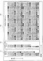
図4は、画像形成機能部40により印刷されるカラーチャート100の一例を示した図である。
図4に示したように、画像形成機能部40により印刷されるカラーチャート100は、判定用ブロック101と、1次元LUT用ブロック102と、4次元LUT用ブロック103により構成されている。
判定用ブロック101には、例えば、出力色空間であるCMYK色空間の1次色である各色成分(C成分,M成分,Y成分,K成分)を10%ステップ毎に印刷した40個のパッチ、CMYK色空間の各色成分の2つを混色させて生成した2次色である青色(B)、緑色(G)、赤色(R)を20%ステップ毎に印刷した15個のパッチ、3色成分(C成分,M成分,Y成分)を混色させて生成した3次色であるグレイトーン(無彩色)を20%ステップ毎に印刷した5個のパッチ、4色成分(C成分,M成分,Y成分,K成分)を混色させて生成した4次色であるグレイトーンを20%ステップ毎に印刷した5個のパッチ、さらには白色の1個のパッチ、の合計66個のパッチが印刷される。
また、1次元LUT用ブロック102には、CMYK色空間の1次色である各色成分(C成分,M成分,Y成分,K成分)を5%ステップ毎に印刷した80個のパッチの中の、判定用ブロック101に形成された40個(10%ステップ毎のもの)を除く40個のパッチが印刷される。
また、4次元LUT用ブロック103には、CMYK色空間の各色成分(C成分,M成分,Y成分,K成分)を20%ステップ毎に混色させた2次色〜4次色である合計625(=54)個のパッチの中の、判定用ブロック101に形成された45個を除く580個のパッチが印刷される。
FIG. 4 is a diagram illustrating an example of a
As shown in FIG. 4, the
The
The one-
The four-
カラーチャート100の判定用ブロック101は、キャリブレーションプロファイルの更新を行うか否か、さらに、1次元LUTを用いたキャリブレーションプロファイルの更新を行うか、キャリブレーションプロファイル全体を新たに作成し直すかを、判定部24が判定するために使用するものである。そのために、判定用ブロック101には、前回の測色時(キャリブレーションプロファイルの更新時)から今回の測色時までの間における、各色座標値の変動量の傾向を判定することが可能となる必要最小限のパッチが形成される。
なお、判定用ブロック101は、各色座標値の変動量の傾向が判定できれば、各パッチはCMYK色空間内で等間隔に形成される必要はなく、不等間隔に形成されてもよい。
The
Note that the
一方、1次元LUT用ブロック102には、キャリブレーションプロファイルを更新するために使用する1次元LUTを算出できる必要充分なパッチが形成される。
また、4次元LUT用ブロック103には、キャリブレーションプロファイル全体を更新するために、出力色空間であるCMYK色空間全体を網羅するパッチが形成される。
On the other hand, in the one-
Further, a patch that covers the entire CMYK color space, which is the output color space, is formed in the four-
<キャリブレーションプロファイルの更新手順の説明>
ユーザによるUI部60からのキャリブレーションプロファイルの更新指示入力に応じて、画像形成機能部40により図4に例示したカラーチャート100が印刷されると、システム制御部30は、ディスプレイ70を介してユーザに対し、測色装置5によりカラーチャート100の判定用ブロック101に形成されたパッチを測色するように指示する。それにより、ユーザが測色装置5により判定用ブロック101に形成されたパッチを測色すると、色調整処理部20の測色データ入力部21が測色装置5にて測色された測色データを取得する。
なお、その際に、ユーザがハンディタイプの手動式の測色装置5を用い、パッチの測色順を間違えた場合には、システム制御部30は、ディスプレイ70にてエラー表示を行う。また、ユーザがスキャンタイプの自動式の測色装置5を用い、カラーチャート100の配置方向を間違えた場合にも、システム制御部30は、ディスプレイ70にてエラー表示を行う。それによって、ユーザに対しカラーチャート100の正確な測色を促す。
<Description of calibration profile update procedure>
When the
At this time, if the user uses the hand-held manual
測色データ入力部21は、測色装置5が測色した判定用ブロック101に形成されたパッチに関し、入力色空間であるL*a*b*色空間での色座標値(L*,a*,b*)を測色データとして測色データ記憶部23に転送する。それにより、測色データ記憶部23は、前回のキャリブレーションでの測色データに加えて、測色装置5が今回測色した判定用ブロック101に形成されたパッチに関する測色データを記憶する。
そして、測色データ記憶部23に測色装置5が測色した測色データが記憶されると、判定部24は、測色データ記憶部23から今回測色された測色データと前回の測色データとを取得する。
The colorimetric
Then, when the color measurement data measured by the
判定部24は、判定用ブロック101に形成されたパッチ各々について、今回測色された測色データと前回の測色データとの差分(色差)を算出する。さらに、例えば、判定用ブロック101に形成されたすべてのパッチでの測色データの色差の平均値(以下、「平均色差」)を算出する。さらに、各色成分(1次色)毎の測色データの色差の平均値(以下、「1次色平均色差」)、複数の色成分を混色させて生成した色(2次色,3次色,4次色)に関する測色データの色差の平均値(以下、「多次色平均色差」)を算出する。
そして、判定部24は、算出した色差(平均色差、1次色平均色差、多次色平均色差)に関しての予め定めた判定基準に基づき、キャリブレーションプロファイルに関する判定を行う。例えば、算出した平均色差が例えば“1”以下であれば、キャリブレーションプロファイルの更新を行わないことを決定する。また、判定部24は、算出した1次色平均色差が例えば “2”以下であって、かつ、各多次色平均色差が“2”以下であれば、1次元LUTを用いたキャリブレーションプロファイルの更新を行うことを決定する。また、判定部24は、これらの何れにも該当しない場合には、キャリブレーションプロファイル全体を新たに作成し直すかの何れかを決定する。
The
Then, the
このように、判定部24は、例えば、判定用ブロック101に形成されたパッチに関し、今回測色された測色データと前回の測色データとの色差を算出する。そして、算出された測色データの色差に基づいて、キャリブレーションプロファイルの更新を行うか否か、さらに、1次元LUTを用いたキャリブレーションプロファイルの更新を行うか、キャリブレーションプロファイル全体を新たに作成し直すかを判定する。それにより、判定用ブロック101に形成されたパッチの測色により、キャリブレーションプロファイルの更新を行わないことや、1次元LUTを用いたキャリブレーションプロファイルの更新を行うだけでよいことが判明する。そのため、パッチ数の多い4次元LUT用ブロック103の測色を行う頻度が低減される。
なお、本実施の形態では、システム制御部30は、カラーチャート100の判定用ブロック101に形成されたパッチを測色するように指示したが、判定用ブロック101に加えて1次元LUT用ブロック102に形成されたパッチ(各色成分の単色パッチ)も測色するように指示してもよい。4次元LUT用ブロック103に比較すれば、1次元LUT用ブロック102のパッチ数は極めて少ないので、測色のためのユーザの負担は大きく増えず、さらには、判定精度の向上も図られるからである。
また、キャリブレーションプロファイルの更新に関する判定を行うに際し、上記した測色データの色差の平均値に代えて、または色差の平均値に加えて、判定用ブロック101に形成されたパッチ各々についての色差の最大値を用いてもよい。
Thus, for example, for the patch formed in the
In this embodiment, the
Further, when making a determination regarding the update of the calibration profile, the color difference of each patch formed in the
<キャリブレーションプロファイルの更新に関する判定方法の他の実施形態>
判定部24は、キャリブレーションプロファイルの更新に関し、次のような判定方法を用いてキャリブレーションプロファイルの更新に関する判定を行うこともできる。
まず、判定部24は、標準データ記憶部22から標準データを取得する。そして、判定部24は、標準データを用いて、入力色空間(L*a*b*色空間)から出力色空間(CMYK色空間)への色変換特性(以下、「逆色変換特性」)を算出する。ここで、この逆色変換特性を算出するに際しては、例えば、標準データ(色座標データ対)に対して加重(重み)を施し回帰分析等の統計処理する方法、標準データについて単純に加重平均を行って補間処理する方法、標準データを学習したニューラルネットワークを用いて統計処理する方法等が用いられる。この場合に、3次元であるL*a*b*色空間の色座標値(L*,a*,b*)から4次元であるCMYK色空間の色座標値(C,M,Y,K)への変換に際しては、既知数不足となるため、一意に解くことはできない。そこで、例えば「単色は単色に変換される」、「2次色は2次色に変換される」とする条件の下で演算を行う。
<Another Embodiment of Determination Method for Updating Calibration Profile>
The
First, the
次に、判定部24は、測色データ記憶部23から今回測色された判定用ブロック101に形成されたパッチ各々に関する測色データ(L*,a*,b*)を取得する。さらには、判定用ブロック101に形成されたパッチ各々の実データ(Cm’,0,0,0),(0,Mm’,0,0),(0,0,Ym’,0),(0,0,0,Km’)と、取得した測色データ(L*,a*,b*)とからなる実データ対を生成する。そして、標準データに基づき算出した上記の逆色変換特性から、この測色データ(L*,a*,b*)に対応する色データ(Cs,0,0,0),(0,Ms,0,0),(0,0,Ys,0),(0,0,0,Ks)を予測する。
それにより、各色(1次色)毎に、予測した色データ(予測色データ)である(Cs,0,0,0),(0,Ms,0,0),(0,0,Ys,0),(0,0,0,Ks)と、判定用ブロック101に形成されたパッチ各々の実データ(Cm’,0,0,0),(0,Mm’,0,0),(0,0,Ym’,0),(0,0,0,Km’)とを対応付けたプロファイル(以下、「判定用プロファイル」)を作成する。この判定用プロファイルは、例えば「(Cs,0,0,0)→(Cm’,0,0,0)」,「(0,Ms,0,0)→(0,Mm’,0,0)」,「(0,0,Ys,0)→(0,0,Ym’,0)」,「(0,0,0,Ks)→(0,0,0,Km’)」からなる1次色毎の1次元ルックアップテーブル(1次元LUT)で構成される。
Next, the
Thereby, for each color (primary color), predicted color data (predicted color data) (C s , 0,0,0), (0, M s , 0,0), (0,0, Y s , 0), (0,0,0, K s ) and actual data (C m ′, 0,0,0), (0, M m ′,) of each patch formed in the
判定部24は、作成した判定用プロファイルでの各成分(グリッド)での調整値(Cm’,0,0,0),(0,Mm’,0,0),(0,0,Ym’,0),(0,0,0,Km’)と、それに対応する色調整部29に設定されているキャリブレーションプロファイルの1次色に関する成分(グリッド)での調整値との差分を算出する。そして、算出された差分に基づいて、キャリブレーションプロファイルの更新に関する判定を行う。
なお、ここでの「調整値」とは、入力された画像データ(C,M,Y,K)に対して、「(C,M,Y,K)→(Cm,Mm,Ym,Km)」に色調整するキャリブレーションプロファイルにおける調整画像データ(Cm,Mm,Ym,Km)をいう。
The
Here, the “adjustment value” means “(C, M, Y, K) → (C m , M m , Y m ) for the input image data (C, M, Y, K). , K m ) ”means the adjustment image data (C m , M m , Y m , K m ) in the calibration profile for color adjustment.
具体的には、判定部24は、判定用プロファイルを構成する各グリッドに対応するキャリブレーションプロファイルでの調整値を求める。そして、判定用プロファイルの各グリッドでの調整値と、それに対応するキャリブレーションプロファイルでの調整値との差分を求める。例えば、C色に関しては、キャリブレーションプロファイルにおける(Cin,0,0,0)での調整値(Cm,0,0,0)を求める。そして、判定用プロファイルでの(Cs,0,0,0)に関する調整値(Cm’,0,0,0)と、キャリブレーションプロファイルでの(Cin(=Cs),0,0,0)に関する調整値(Cm,0,0,0)との差分「Cm’−Cm」を求める。M色,Y色,K色についても同様である。
Specifically, the
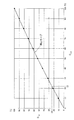
ここで、図5は、一例として、C色(1次色)に関するキャリブレーションプロファイルと、判定用プロファイルのC色グリッドでの調整値C’とを示した図である。図5に示すように、例えば、Cin=Cs=53においては、キャリブレーションプロファイルでの調整値(59,0,0,0)と判定用プロファイルでの調整値(60,0,0,0)とが対応付けられる。そこで、この場合の差分は、60−59=1となる。
このようにして、C色、M色、Y色、K色についてキャリブレーションプロファイルでの調整値と判定用プロファイルでの調整値との差分を算出する。そして、算出された差分に基づいて、キャリブレーションプロファイルの更新を行うか否か、さらに、1次元LUTを用いたキャリブレーションプロファイルの更新を行うか、キャリブレーションプロファイル全体を新たに作成し直すかを判定してもよい。
Here, FIG. 5 is a diagram showing, as an example, a calibration profile related to the C color (primary color) and an adjustment value C ′ in the C color grid of the determination profile. As shown in FIG. 5, for example, when C in = C s = 53, the adjustment value (59,0,0,0) in the calibration profile and the adjustment value (60,0,0,0) in the determination profile are used. 0). Therefore, the difference in this case is 60−59 = 1.
In this way, the difference between the adjustment value in the calibration profile and the adjustment value in the determination profile is calculated for the C, M, Y, and K colors. Then, based on the calculated difference, whether to update the calibration profile, whether to update the calibration profile using the one-dimensional LUT, or to newly create the entire calibration profile You may judge.
この場合に、算出された差分を入力画像データCin,Min,Yin,Kinの大きさに対応させて判定基準を設定してもよい。すなわち、入力画像データCin,Min,Yin,Kinを例えば0〜30%、31〜60%、61〜100%の3つのエリアに区分けする(図5参照)。そして、それぞれのエリアでの差分に応じて、キャリブレーションプロファイルの更新に関する判定基準を設定してもよい。
例えば、判定部24は、次のような判定基準を用いることができる。すなわち、判定部24は、入力画像データのC色(Cin),M色(Min),Y色(Yin),K色(Kin)それぞれに関して、0〜30%エリアでの差分が“2”以下、かつ、31〜60%エリアでの差分が“3”以下、かつ、61〜100%エリアでの差分が“4”以下である場合には、キャリブレーションプロファイルの更新を行わないことを決定する。また、判定部24は、0〜30%エリアでの差分が“3”以下、かつ、31〜60%エリアでの差分が“4”以下、かつ、61〜100%エリアでの差分が“6”以下である場合には、1次元LUTを用いたキャリブレーションプロファイルの更新を行うことを決定する。また、判定部24は、これらの何れにも該当しない場合には、キャリブレーションプロファイル全体を新たに作成し直すかの何れかを決定する。
In this case, the determination reference may be set by corresponding the calculated difference to the sizes of the input image data C in , M in , Y in , and K in . That is, the input image data C in , M in , Y in , and K in are divided into, for example, three areas of 0 to 30%, 31 to 60%, and 61 to 100% (see FIG. 5). Then, a criterion for updating the calibration profile may be set according to the difference in each area.
For example, the
<キャリブレーションプロファイルの更新に関する判定方法の他の実施形態>
さらには、判定部24は、キャリブレーションプロファイルの更新に関し、次のような判定方法を用いてキャリブレーションプロファイルの更新に関する判定を行うこともできる。
すなわち、判定部24は、1次色だけでなく、多次色(2次色,3次色,4次色)に関しても判定用プロファイルを作成する。そして、判定用プロファイルを構成する各グリッドに対応するキャリブレーションプロファイルでの調整値を求める。
それにより、まず、判定用プロファイルにおける多次色の各グリッドでの調整値とキャリブレーションプロファイルでの調整値との色空間内での距離(ユークリッド距離)を求める。例えば、同一の入力画像データ(Cin,Min,0,0)に関して、判定用プロファイルでの調整値(Cm2’,Mm2’,0,0)とキャリブレーションプロファイルでの調整値(Cm2,Mm2,0,0)との色空間内での距離Dを求める。この場合には、D=((Cm2’−Cm2)2+(Mm2’−Mm2)2)1/2を求めることとなる。
さらに、この多次色を構成する各色成分(C色成分,M色成分)と同じ色座標値からなる1次色(Cin,0,0,0),(0,Min,0,0)に関しての、判定用プロファイルでの調整値(Cm1’,0,0,0),(0,Mm1’,0,0)とキャリブレーションプロファイルでの調整値(Cm1,0,0,0),(0,Mm1,0,0)との差分を求める。この場合には、差分「Cm1’−Cm1」と、差分「Mm1’−Mm1」とを求める。
そして、例えばそれぞれのエリア(図5参照)での1次色および多次色各々での差分を用いて、キャリブレーションプロファイルの更新に関する判定を行う。
<Another Embodiment of Determination Method for Updating Calibration Profile>
Furthermore, the
That is, the
Thereby, first, the distance (Euclidean distance) in the color space between the adjustment value in each grid of multi-order colors in the determination profile and the adjustment value in the calibration profile is obtained. For example, for the same input image data (C in , M in , 0,0), the adjustment value (C m2 ′, M m2 ′, 0,0) in the determination profile and the adjustment value (C in the calibration profile) m2, M m2, obtains a distance D in the color space between 0,0). In this case, D = ((C m2 ′ −C m2 ) 2 + (M m2 ′ −M m2 ) 2 ) 1/2 is obtained.
Further, primary colors (C in , 0,0,0), (0, M in , 0,0) having the same color coordinate values as the color components (C color component, M color component) constituting this multi-order color. ) Regarding the adjustment value (C m1 ′, 0,0,0), (0, M m1 ′, 0,0) and the adjustment value (C m1 , 0,0, 0), (0, M m1 , 0,0) is obtained. In this case, the difference “C m1 ′ −C m1 ” and the difference “M m1 ′ −M m1 ” are obtained.
Then, for example, the determination regarding the update of the calibration profile is performed using the difference between the primary color and the multi-order color in each area (see FIG. 5).
例えば、判定部24は、次のような判定基準を用いることができる。すなわち、判定部24は、上記した多次色に関して、まず、多次色としての距離D=((Cm2’−Cm2)2+(Mm2’−Mm2)2)1/2が各エリア毎に予め定めた範囲内にあるかを判定する。そして、この距離Dが、例えば、0〜30%エリアにおいて“2”以下、かつ、31〜60%エリアにおいて“3”以下、かつ、61〜100%エリアにおいて“4”以下である場合には、キャリブレーションプロファイルの変動が小さいと判断し、キャリブレーションプロファイルの更新を行わないことを決定する。
この距離D=((Cm2’−Cm2)2+(Mm2’−Mm2)2)1/2が、例えば、0〜30%エリアにおいて“3”以下、かつ、31〜60%において“4”以下、かつ、61〜100%エリアにおいて“6”以下である場合には、さらに、次のようにして多次色に関する調整量と1次色に関する調整量とが同じ傾向を示しているか否かを判定する。例えば、判定部24は、多次色(ここでは、2次色)を構成する各色成分(ここでは、C色成分,M色成分)に着目し、多次色を変換(調整)した場合のその各色成分の差分と、単色(1次色)として変換(調整)した場合の差分とを比較する。すなわち、多次色を構成する各色成分(C色成分,M色成分)毎に、多次色を調整した場合のその各色成分の差分「Cm2’−Cm2」、「Mm2’−Mm2」と、1次色として調整した場合の差分「Cm1’−Cm1」、「Mm1’−Mm1」との間の相互の差分を求める。この場合には、C色成分についての差分△C=「Cm2’−Cm2」−「Cm1’−Cm1」と、M色成分についての差分△M=「Mm2’−Mm2」−「Mm1’−Mm1」とを求める。
そして、エリア全域(0〜100%)において、差分△Cおよび差分△Mの双方が“±2”以内であれば、多次色に関する調整量と1次色に関する調整量とが同じ傾向を示していると判断し、1次元LUTを用いてキャリブレーションプロファイルの充分な更新を行うことができると判定する。それにより、1次元LUTを用いたキャリブレーションプロファイルの更新を行うことを決定する。
また、判定部24は、これらの何れにも該当しない場合には、キャリブレーションプロファイル全体を新たに作成し直すことを決定する。
For example, the
This distance D = ((C m2 ′ −C m2 ) 2 + (M m2 ′ −M m2 ) 2 ) 1/2 is, for example, “3” or less in the 0 to 30% area, and 31 to 60%. When “4” or less and “6” or less in the 61 to 100% area, the adjustment amount for the multi-color and the adjustment amount for the primary color show the same tendency as follows. It is determined whether or not. For example, the
If the difference ΔC and the difference ΔM are both within “± 2” in the entire area (0 to 100%), the adjustment amount for the multi-color and the adjustment amount for the primary color show the same tendency. It is determined that the calibration profile can be sufficiently updated using the one-dimensional LUT. Thus, it is determined to update the calibration profile using the one-dimensional LUT.
In addition, when none of these applies, the
<キャリブレーションプロファイルの更新を行わない場合の説明>
次に、判定部24は、上記した判定基準に基づき、キャリブレーションプロファイルの更新を行わないことを決定した場合には、その旨をシステム制御部30に通知する。キャリブレーションプロファイルの更新を行わない旨の通知を受けたシステム制御部30は、ディスプレイ70にキャリブレーションプロファイルの更新は不要であり、測色装置5によるカラーチャート100の測色を行う必要のないことを表示する。それにより、ユーザは、測色装置5による判定用ブロック101以外の1次元LUT用ブロック102および4次元LUT用ブロック103に形成されたパッチの測色を中止する。
このように、本実施の形態の画像形成システム1では、キャリブレーションプロファイルの更新が不要であることが、カラーチャート100の判定用ブロック101の測色によって判明する。そのため、例えばユーザがハンディタイプの手動式の測色装置5を用いている場合には、その測色のためのユーザの操作工数が低減される。
<Explanation when calibration profile is not updated>
Next, when the
As described above, in the image forming system 1 according to the present embodiment, it is found by the colorimetry of the determination block 101 of the
<1次元LUTを用いたキャリブレーションプロファイルの更新を行う場合の説明>
次に、判定部24は、上記した判定基準に基づき、1次元LUTを用いたキャリブレーションプロファイルの更新を行うことを決定した場合には、その旨をシステム制御部30および1次元LUT算出部25に通知する。1次元LUTを用いたキャリブレーションプロファイルの更新を行う旨の通知を受けたシステム制御部30は、ディスプレイ70において、測色装置5によりカラーチャート100の1次元LUT用ブロック102の測色を行うことを指示する表示を行う。それにより、ユーザは、測色装置5により1次元LUT用ブロック102に形成されたパッチの測色を行う。
このように、本実施の形態の画像形成システム1では、キャリブレーションプロファイルの更新は1次元LUT用ブロック102の測色データを用いて行うことで充分であることが、カラーチャート100の判定用ブロック101の測色によって判明する。そのため、例えばユーザがハンディタイプの手動式の測色装置5を用いている場合には、その測色のためのユーザの操作工数が低減される。
<Explanation when updating calibration profile using one-dimensional LUT>
Next, when the
As described above, in the image forming system 1 according to the present embodiment, it is sufficient to update the calibration profile by using the colorimetric data of the one-
1次元LUTを用いたキャリブレーションプロファイルの更新を行う旨の通知を受けた1次元LUT算出部25は、測色データ記憶部23から測色装置5にて今回測色された判定用ブロック101および1次元LUT用ブロック102に形成されたパッチ各々に関する測色データ(L1 *,a1 *,b1 *)を取得する。さらに、測色データ記憶部23から前回のキャリブレーション時に測色された判定用ブロック101および1次元LUT用ブロック102に形成されたパッチ各々に関する測色データ(L2 *,a2 *,b2 *)を取得する。そして、今回の測色データ(L1 *,a1 *,b1 *)と前回の測色データ(L2 *,a2 *,b2 *)とにおける紙白(L0 *,a0 *,b0 *)からの色差を算出する。色差は、L*a*b*色空間でのそれぞれ測色データ(L1 *,a1 *,b1 *)および測色データ(L2 *,a2 *,b2 *)と紙白(L0 *,a0 *,b0 *)とのユークリッド距離D1,D2(1次元の値)である。
それにより、色差D1および色差D2と、判定用ブロック101および1次元LUT用ブロック102に形成されたパッチ(各色成分の単色パッチ)各々に関する各色成分値とからなるデータ対を作成する。すなわち、今回測色された測色データに関してのデータ対(D1,C)、(D1,M)、(D1,Y)、(D1,K)と、前回測色された測色データに関してのデータ対(D2,C)、(D2,M)、(D2,Y)、(D2,K)とを作成する。ここでのC,M,Y,Kは、パッチ各々での実データである。
The one-dimensional
As a result, a data pair composed of the color difference D1 and the color difference D2 and each color component value relating to each of the patches (monochromatic patches of each color component) formed in the
そして、1次元LUT算出部25は、パッチ各々についての今回の測色データに関してのデータ対(D1,C)、(D1,M)、(D1,Y)、(D1,K)と、前回の測色データに関してのデータ対(D2,C)、(D2,M)、(D2,Y)、(D2,K)とから、各色成分(1次色)毎に、前回の調整値(Cm2,Mm2,Ym2,Km2)と今回の調整値(Cm1,Mm1,Ym1,Km1)とのそれぞれの対応関係を示す補正カーブを算出する。すなわち、パッチ各々での実データC,M,Y,Kは同一であるが、前回の測色と今回の測色とで測色データが異なる値を有するので、パッチ各々についての色差D1と色差D2とは異なる。そこで、1次元の値である色差(D1およびD2)を介してパッチ各々に関する実データC,M,Y,Kを対応付ければ、前回の調整値(Cm2,Mm2,Ym2,Km2)と今回の調整値(Cm1,Mm1,Ym1,Km1)とがそれぞれ対応付けられる。そして、対応付けられた前回の調整値と今回の調整値とについて、各色成分(1次色)毎に、それぞれ補間演算や突き当て処理等を用いて補正カーブを算出する。
なお、補正カーブ(1次元LUT)を算出するために、ここではL*a*b*色空間という3次元のデータを、紙白からの色差を求めることで1次元のデータにする例を挙げたが、補正カーブ(1次元LUT)を算出する方法としてはこれに限定するものではない。例えば、濃度値をL*a*b*色空間での測色値と同時に測色できる測色装置を使用する場合には、1次元LUTの算出に関しては測色値(L*,a*,b*)ではなく、濃度値を使うことで対応してもよい。
The one-dimensional
In order to calculate a correction curve (one-dimensional LUT), here, an example is given in which three-dimensional data of L * a * b * color space is converted into one-dimensional data by obtaining a color difference from paper white. However, the method for calculating the correction curve (one-dimensional LUT) is not limited to this. For example, when using a color measurement device that can measure the density value simultaneously with the color measurement value in the L * a * b * color space, the color measurement value (L * , a * , Instead of b * ), a density value may be used.
ここで、図6は、一例として、色差(D1,D2)を介して算出したC成分についての前回の調整値Cm2と今回の調整値Cm1との対応関係を示す補正カーブを例示した図である。図6に例示した補正カーブでは、例えば、前回の調整値Cm2=22が、今回の調整値Cm1=24に対応付けられる。
このように、1次元LUT算出部25は、図6に例示した補正カーブを、例えば前回の調整値Cm2(=1〜100%)と、それに対応付けられる今回の調整値Cm1(=1〜100%)との組み合わせで構成される1次元LUTとして作成する。M成分,Y成分,K成分についても同様である。
そして、1次元LUT算出部25は、作成した各色成分毎の1次元LUTを第1更新部26に出力する。
Here, FIG. 6 is a diagram illustrating, as an example, a correction curve indicating the correspondence between the previous adjustment value C m2 and the current adjustment value C m1 for the C component calculated through the color difference (D1, D2). It is. In the correction curve illustrated in FIG. 6, for example, the previous adjustment value C m2 = 22 is associated with the current adjustment value C m1 = 24.
As described above, the one-dimensional
Then, the one-dimensional
第1更新部26は、1次元LUT算出部25から取得した各色成分毎の1次元LUTを用いて、色調整部29に設定されているキャリブレーションプロファイルを構成するすべてのグリッド(1次色成分,2次色成分,3次色成分,4次色成分)を補正する。
例えば、前回のキャリブレーションによって生成されたキャリブレーションプロファイルを構成する1のグリッドが、(Cin,Min,Yin,Kin)=(20,30,70,20)を調整値(Cm2,Mm2,Ym2,Km2)=(22,28,69,22)に調整するものであった場合を想定する。この場合には、例えば図6に例示したC色成分の1次元LUTにより、C2=22がC1=24に補正される。同様に、ここでは、M色成分の1次元LUTによりM2=28がM1=30、Y色成分の1次元LUTによりY2=69がY1=70、K色成分の1次元LUTによりK2=22がK=23に補正されるとする。そうすると、今回の1次元LUT(補正カーブ)によるキャリブレーションの更新により、(Cin,Min,Yin,Kin)=(20,30,70,20)を調整値(Cm1,Mm1,Ym1,Km1)=(24,30,70,23)に調整するキャリブレーションプロファイルが生成される。
The
For example, one grid constituting the calibration profile generated by the previous calibration has an adjustment value (C m2 ) of (C in , M in , Y in , K in ) = (20, 30, 70, 20). , M m2 , Y m2 , K m2 ) = (22, 28, 69, 22) is assumed. In this case, for example, C 2 = 22 is corrected to C 1 = 24 by the one-dimensional LUT of the C color component illustrated in FIG. Similarly, where, Y 2 = 69 M 2 = 28 is the one-dimensional LUT of M 1 = 30, Y color component by one-dimensional LUT of M color components by a one-dimensional LUT for Y 1 = 70, K color component Assume that K 2 = 22 is corrected to K = 23. Then, (C in , M in , Y in , K in ) = (20, 30, 70, 20) is adjusted to an adjustment value (C m1 , M m1 ) by updating the calibration by the current one-dimensional LUT (correction curve). , Y m1 , K m1 ) = (24, 30, 70, 23) is generated.
また、1次元LUT算出部25は、次のように1次元LUTとしての補正カーブを作成してもよい。
すなわち、1次元LUT算出部25は、前回のキャリブレーションにより生成されたキャリブレーションプロファイルと、今回測色された判定用ブロック101および1次元LUT用ブロック102のパッチ各々に関するL*a*b*色空間での測色データ(L1 *,a1 *,b1 *)およびパッチ各々に関する実データ(C,M,Y,K)とからなる実データ対、および標準データとにより、1次元LUTを作成してもよい。
The one-dimensional
In other words, the one-dimensional
具体的には、1次元LUT算出部25は、前回のキャリブレーションにより色調整部29に設定されているキャリブレーションプロファイルにおける各色成分(1次色)のグリッドを抽出する。そして、1次色のグリッドの座標点(C,0,0,0),(0,M,0,0),(0,0,Y,0),(0,0,0,K)と、それに対応する調整値(Cm1,0,0,0),(0,Mm1,0,0),(0,0,Ym1,0),(0,0,0,Km1)とをそれぞれ対応付けた各色成分の調整カーブ(第1調整カーブ)を作成する。
Specifically, the one-dimensional
また、今回測色された判定用ブロック101および1次元LUT用ブロック102に形成されたパッチ各々に関する測色データ(L1 *,a1 *,b1 *)およびパッチ各々に関する実データ(Cm2,0,0,0),(0,Mm2,0,0),(0,0,Ym2,0),(0,0,0,Km2)とからなる実データ対と、標準データにおける各色成分(1次色)についての(L*,a*,b*)およびパッチ各々に関する色データ(C,0,0,0),(0,M,0,0),(0,0,Y,0),(0,0,0,K)とから、標準データにおける色データ(C,0,0,0),(0,M,0,0),(0,0,Y,0),(0,0,0,K)と、それに対応するパッチ各々に関する実データ(Cm2,0,0,0),(0,Mm2,0,0),(0,0,Ym2,0),(0,0,0,Km2)とをそれぞれ対応付けた各色成分の調整カーブ(第2調整カーブ)を作成する。
第2調整カーブの算出に際しては、上記の場合と同様に、測色データ(L1 *,a1 *,b1 *)および標準データ(L*,a*,b*)と紙白との色差を求め、1次元の値である色差を介して標準データにおけるC,M,Y,Kとパッチ各々に関する実データC1,M1,Y1,K1とをそれぞれ対応付ける。そして、対応付けられた標準データのC,M,Y,Kとパッチ各々の実データC1,M1,Y1,K1とについて、それぞれ補間演算や突き当て処理等を用いて第2調整カーブを算出する。
Further, the color measurement data (L 1 * , a 1 * , b 1 * ) relating to each of the patches formed in the
When calculating the second adjustment curve, the colorimetric data (L 1 * , a 1 * , b 1 * ) and the standard data (L * , a * , b * ) and the paper white are calculated in the same manner as described above. A color difference is obtained, and C, M, Y, K in the standard data and actual data C 1 , M 1 , Y 1 , K 1 for each patch are associated with each other through the color difference, which is a one-dimensional value. Then, the second adjustment is performed on the associated standard data C, M, Y, K and the actual data C 1 , M 1 , Y 1 , K 1 of each patch by using an interpolation operation or a butting process, respectively. Calculate the curve.
ここで、図7は、一例として、色調整部29に設定されているキャリブレーションプロファイルを基に作成したC色成分についての第1調整カーブと、今回の測色データを基に作成したC色成分についての第2調整カーブとを例示した図である。図7に例示した第1調整カーブと第2調整カーブとにより、例えば、同一の実データ(C,0,0,0)における第1調整カーブ上の調整値(Cm1,0,0,0)と第2調整カーブ上の調整値(Cm2,0,0,0)とを対応付けることにより、補正カーブを作成することができる。図7の例では、実データC=35において、前回のキャリブレーションプロファイルによる第1調整カーブ上の調整値Cm1=38は、今回の測色データによる第2調整カーブ上の調整値Cm2=40に対応付けられることとなる。それにより、実データ(0,0,0,0)〜(100,0,0,0)について1ステップ毎に第1調整カーブ上の調整値Cm1と第2調整カーブ上の調整値Cm2とを対応付けることで、C色成分に関する1次元LUTとしての補正カーブを作成する。M色成分,Y色成分,K色成分についても同様である。
Here, FIG. 7 shows, as an example, the first adjustment curve for the C color component created based on the calibration profile set in the
<キャリブレーションプロファイル全体を新たに作成し直す場合の説明>
次に、判定部24は、上記した判定基準に基づき、キャリブレーションプロファイル全体を新たに作成し直すことを決定した場合には、その旨をシステム制御部30および多次元LUT算出部27に通知する。キャリブレーションプロファイル全体を新たに作成し直す旨の通知を受けたシステム制御部30は、ディスプレイ70において、測色装置5によりカラーチャート100の1次元LUT用ブロック102および4次元LUT用ブロック103の測色をさらに行うことを指示する表示を行う。それにより、ユーザは、測色装置5により1次元LUT用ブロック102および4次元LUT用ブロック103に形成されたパッチの測色を行う。これによって、新たに作成し直したキャリブレーションプロファイルによって色調整部29に設定されているキャリブレーションプロファイルの更新を行う。
このように、本実施の形態では、判定部24にて予め定めた判定基準によってキャリブレーションプロファイル全体を新たに作成し直すことを決定した場合においてのみ、4次元LUT用ブロック103の測色を行う。そのため、キャリブレーションプロファイル全体を新たに作成し直すための測色は必要な場合においてのみ行われることとなる。
<Explanation when re-creating the entire calibration profile>
Next, when the
As described above, in the present embodiment, the color measurement of the four-
なお、システム制御部30は、キャリブレーションが画像形成システム1での最初に行うキャリブレーションである場合には、キャリブレーションプロファイル全体を新たに作成するので、カラーチャート100全体(判定用ブロック101、1次元LUT用ブロック102、4次元LUT用ブロック103)に形成されたパッチを行うことを指示する表示を行う。
Since the
測色装置5により1次元LUT用ブロック102および4次元LUT用ブロック103に形成されたパッチの測色が行われると、多次元LUT算出部27は、測色データ記憶部23から測色装置5にて測色されたカラーチャート100全体(判定用ブロック101、1次元LUT用ブロック102、4次元LUT用ブロック103)に形成されたパッチ各々に関するL*a*b*色空間での測色データ(L*,a*,b*)を取得する。さらに、カラーチャート100全体に形成されたパッチ各々の実データ(C,M,Y,K)と、測色装置5にて測色された測色データ(L*,a*,b*)とからなる実データ対を生成する。そして、この実データ(C,M,Y,K)と測色データ(L*,a*,b*)とからなる実データ対を用いて、現在の画像形成機能部40における色再現性を表す入力色空間(L*a*b*色空間)から出力色空間(CMYK色空間)への逆色変換特性を算出する。
When the
さらに、多次元LUT算出部27は、標準データ記憶部22から標準データを取得する。そして、多次元LUT算出部27は、画像形成機能部40が印刷した色座標値(C,M,Y,K)を得るために入力されるべき色座標値(L*,a*,b*)を予想する、出力色空間(CMYK色空間)から入力色空間(L*a*b*色空間)への色変換特性(以下、「順色変換特性」)を算出する。
ここで、逆色変換特性や順色変換特性を算出するに際しては、例えば、標準データ(色座標データ対)に対して加重(重み)を施し回帰分析等の統計処理する方法、標準データについて単純に加重平均を行って補間処理する方法、標準データを学習したニューラルネットワークを用いて統計処理する方法等が用いられる。
Further, the multidimensional
Here, when calculating inverse color conversion characteristics and forward color conversion characteristics, for example, standard data (color coordinate data pair) is weighted (weighted) and subjected to statistical processing such as regression analysis. For example, a weighted average is used for interpolation processing, and a statistical processing is performed using a neural network that has learned standard data.
そして、多次元LUT算出部27は、CMYK色空間の各色成分(C成分,M成分,Y成分,K成分)を予め定めたステップ毎(例えば、10%毎)に区切った格子点(C,M,Y,K)を作成し、順色変換特性を用いて各格子点をL*a*b*色空間の色座標値(L*,a*,b*)に変換する。さらに、逆色変換特性を用いて、L*a*b*色空間の色座標値(L*,a*,b*)をCMYK色空間の色座標値(C’,M’,Y’,K’)に変換する。
この場合に、3次元であるL*a*b*色空間の色座標値(L*,a*,b*)から4次元であるCMYK色空間の色座標値(C’,M’,Y’,K’)への変換に際しては、既知数不足となるため、一意に解くことはできない。そこで、この場合は、例えば、「単色は単色に変換される」、「2次色は2次色に変換される」とする拘束条件の下で演算する。
Then, the multidimensional
In this case, the color coordinate values (C ′, M ′, Y) of the four-dimensional CMYK color space from the color coordinate values (L * , a * , b * ) of the three-dimensional L * a * b * color space. When converting to ', K'), the known number is insufficient and cannot be solved uniquely. Therefore, in this case, for example, the calculation is performed under a constraint condition that “a single color is converted into a single color” and “a secondary color is converted into a secondary color”.
このようにして、多次元LUT算出部27は、格子点(C,M,Y,K)と、順色変換特性および逆色変換特性を用いて算出した色座標値(C’,M’,Y’,K’)との組み合わせ(キャリブレーションプロファイル)を作成する。キャリブレーションプロファイルは、例えば10%毎のステップで区切った格子点(C,M,Y,K)を用いた場合には、全体として114個のデータ対により構成されることとなる。
そして、多次元LUT算出部27は、作成したキャリブレーションプロファイル(4次元LUT)を第2更新部28に出力する。
第2更新部28は、多次元LUT算出部27により新たに作成したキャリブレーションプロファイルにより、色調整部29に設定されているキャリブレーションプロファイルを置き(書き)換える。
In this way, the multidimensional
Then, the multidimensional
The
<判定部が行う判定処理の説明>
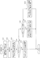
ここで、判定部24が行うキャリブレーションプロファイルの更新に関する判定処理について説明する。図8は、判定部24が行うキャリブレーションプロファイルの更新に関する判定処理の内容の一例を示したフローチャートである。
図8に示すように、判定部24は、測色データ記憶部23に測色装置5が測色した測色データが記憶されると、測色データ記憶部23から今回測色された測色データと前回の測色データとを取得する(ステップ101)。そして、判定部24は、今回測色された測色データと前回の測色データとの色差を算出する(ステップ102)。
そして、判定部24は、例えば、算出された測色データの色差に関しての予め定めた判定基準に基づき、キャリブレーションプロファイルの更新を行うか否か、さらに、1次元LUTを用いたキャリブレーションプロファイルの更新を行うか、キャリブレーションプロファイル全体を新たに作成し直すかを判定する(ステップ103)。
<Description of determination process performed by determination unit>
Here, a determination process related to the calibration profile update performed by the
As shown in FIG. 8, when the colorimetric data measured by the
Then, the
判定部24は、キャリブレーションプロファイルの更新を行わないことを決定した場合には(ステップ104でYes)、その旨をシステム制御部30に通知し(ステップ105)、判定処理を終了する。
それより、システム制御部30は、ディスプレイ70にキャリブレーションプロファイルの更新は不要であり、測色装置5によるカラーチャート100の測色を行う必要のないことを表示する。
If the
Accordingly, the
判定部24は、1次元LUTを用いたキャリブレーションプロファイルの更新を行うことを決定した場合には(ステップ104でNo、ステップ106でYes)、その旨をシステム制御部30および1次元LUT算出部25に通知し(ステップ107)、判定処理を終了する。
それにより、システム制御部30は、ディスプレイ70において、測色装置5によりカラーチャート100の1次元LUT用ブロック102の測色を行うことを指示する表示を行う。また、1次元LUT算出部25は、キャリブレーションプロファイルの更新に使用する1次元LUTを算出する。
If the
Thereby, the
また、判定部24は、キャリブレーションプロファイル全体を新たに作成し直すことを決定した場合には(ステップ104でNo、ステップ106でNo)、その旨をシステム制御部30および多次元LUT算出部27に通知し(ステップ108)、判定処理を終了する。
それにより、システム制御部30は、ディスプレイ70において、測色装置5によりカラーチャート100の1次元LUT用ブロック102および4次元LUT用ブロック103の測色をさらに行うことを指示する表示を行う。また、多次元LUT算出部27は、キャリブレーションプロファイル全体を新たに作成する。
In addition, when the
As a result, the
なお、本実施の形態の判定部24では、キャリブレーションプロファイルの更新を行うか否か、さらに、キャリブレーションプロファイルの更新を行うとした場合に、1次元LUTを用いたキャリブレーションプロファイルの更新を行うか、キャリブレーションプロファイル全体を新たに作成し直すかを判定する構成とした。このような構成の他に、キャリブレーションプロファイルの更新を行うとした場合に、例えば、1次元LUTを用いたキャリブレーションプロファイルの更新を行うか、キャリブレーションプロファイルの中の一部、例えばY色成分,M色成分,C色成分についての3次元LUT部分または3色成分(C成分,M成分,Y成分)を混色させて生成した3次色部分を新たに作成し直す更新を行うか、さらには、キャリブレーションプロファイル全体を新たに作成し直すかを判定する構成といったように、さらに多段階の更新判定を行う設定としてもよい。
Note that the
[実施の形態2]
<色調整処理部の説明>
次に、上記の画像処理部10に備えられる色調整処理部20の他の実施の形態について説明する。ここでは、画像形成システム1(画像形成機能部40)に使用する色材として、例えばLC(ライトシアン)色とDC(ダークシアン)色、LM(ライトマゼンタ)色とDM(ダークマゼンタ)色、Y色、K色の6色を用いる構成について述べる。LC色は、色調が明るい(明度および彩度の何れか一つ、またはその双方が相対的に高い)シアンであり、DC色は、LC色に比べて色調が暗い(明度および彩度の何れか一または双方が相対的に低い)シアンである。また、LM色は、色調が明るいマゼンタであり、DM色は、LM色に比べて色調が暗いマゼンタである。
画像データにおけるLC色成分およびDC色成分は、色調整処理部20において、C色成分を予め定めた色分解テーブルにより分解することにより生成される。同様に、LM色成分およびDM色成分は、色調整処理部20において、M色成分を予め定めた色分解テーブルにより分解することにより生成される。
[Embodiment 2]
<Description of Color Adjustment Processing Unit>
Next, another embodiment of the color
The LC color component and the DC color component in the image data are generated by the color
図9は、本実施の形態の色調整処理部20の構成を示すブロック図である。
図9に示すように、本実施の形態の色調整処理部20には、上記の図3に示した実施の形態1の構成に加えて、C色成分をLC色成分およびDC色成分に、M色成分をLM色成分およびDM色成分にそれぞれ色分解する色分解手段の一例としての色分解部51、色分解を行う際に使用する分解係数群の一例としての色分解テーブルを更新するための色分解テーブルを算出する色分解テーブル算出部52、色分解テーブル算出部52にて算出された色分解テーブルにより色分解部51に設定された色分解テーブルを更新する第3更新部53を備えている。
FIG. 9 is a block diagram showing a configuration of the color
As shown in FIG. 9, the color
ここでの色分解テーブルは、色成分(C色成分,M色成分)を第1色成分(LC色成分,LM色成分)と第2色成分(DC色成分,DM色成分)とに分解する際の第1色成分の値と第2色成分の値とを定めるものである。
図10は、色分解部51に設定されたC色成分に関する色分解テーブルの一例を示した図である。図10に例示した色分解テーブルでは、C色成分の色座標値(横軸)に応じた比率で、C色成分をLC色成分とDC色成分とに分解する。例えば、C色成分の色座標値が60%である場合には、LC色成分の値が80%、DC色成分の値が40%となるように分解する。
The color separation table here separates the color components (C color component, M color component) into the first color component (LC color component, LM color component) and the second color component (DC color component, DM color component). The value of the first color component and the value of the second color component are determined.
FIG. 10 is a diagram illustrating an example of a color separation table for the C color component set in the
色分解テーブル算出部52は、色調整部29に設定されるキャリブレーションプロファイルの場合と同様に、判定部24での判定結果に応じて色分解テーブルを算出する。
この場合、判定部24は、後段に述べるカラーチャートの判定用ブロックに関する測色データを用いて、色分解テーブルの更新が必要か否かを判定(決定)する。例えば、判定部24は、予め定めた判定基準に基づき、(1)キャリブレーションプロファイルおよび色分解テーブルの双方の更新を行わない旨の決定、(2)1次元LUTを用いたキャリブレーションプロファイルのみの更新を行う旨の決定、(3)1次元LUTを用いたキャリブレーションプロファイルの更新および色分解テーブルの更新を行う旨の決定、(4)キャリブレーションプロファイル全体を新たに作成し直す旨の決定、(5)キャリブレーションプロファイル全体を新たに作成し直し、かつ、色分解テーブルの更新を行う旨の決定の何れかを行う。そして、判定部24が色分解テーブルの更新が必要と決定した(3)および(5)のケースにおいて、色分解テーブル算出部52は、C色成分およびM色成分に関する色分解テーブルを算出する。
第3更新部53は、色分解テーブル算出部52にて算出されたC色成分およびM色成分に関する色分解テーブルを用いて、色分解部51に設定されているC色成分およびM色成分に関する色分解テーブルを補正する。
The color separation
In this case, the
The
<キャリブレーションプロファイルおよび色分解テーブルの更新手順の説明>
システム制御部30(図1参照)は、例えばUI部60にてユーザからキャリブレーションプロファイルおよび色分解テーブルの更新を指示する操作入力を受け付けると、画像形成機能部40に対し、まず、判定部24がキャリブレーションプロファイルおよび色分解テーブルの更新に関する判定を行う際に用いる色見本(パッチ)からなる判定用ブロックと、色分解テーブルを更新するために使用する色分解テーブルを算出するためのパッチからなる色分解テーブル用ブロックと、により構成される第1カラーチャートを印刷するように指示する。
さらに、システム制御部30は、ディスプレイ70を介してユーザに対し、測色装置5により第1カラーチャートの判定用ブロックに形成されたパッチを測色するように指示する。それにより、ユーザが測色装置5により判定用ブロックに形成されたパッチを測色すると、色調整処理部20の測色データ入力部21が測色装置5にて測色された測色データを取得する。測色データ入力部21は、取得した測色データを測色データ記憶部23に転送し、測色データ記憶部23は、前回の測色データに加えて、今回の測色データを記憶する。
<Description of update procedure of calibration profile and color separation table>
For example, when the system control unit 30 (see FIG. 1) receives an operation input instructing to update the calibration profile and the color separation table from the user in the
Further, the
この場合の判定用ブロックには、上記図4に示したカラーチャート100の判定用ブロック101に印刷した66個のパッチに加えて、LC色成分,DC色成分,LM色成分,DM色成分を10%ステップ毎に印刷した40個のパッチが印刷される。
また、色分解テーブル用ブロックには、LC色成分,DC色成分をそれぞれ10%ステップ毎に変えて混色させて印刷した121個のパッチ、LM色成分,DM色成分をそれぞれ10%ステップ毎に変えて混色させて印刷した121個のパッチ、の合計242個のパッチが印刷される。
In the determination block in this case, in addition to the 66 patches printed on the determination block 101 of the
In the color separation table block, 121 patches printed by changing the LC color component and the DC color component every 10% steps, and the LM color component and DM color component are printed every 10% step. A total of 242 patches, 121 patches printed with different colors and mixed, are printed.
判定部24は、色調整部29に設定されるキャリブレーションプロファイルの場合と同様の判定基準により、上記(1)〜(5)の何れかを決定する。例えば、判定部24は、測色データ記憶部23から、判定用ブロックに形成されたパッチ各々に関する今回測色された測色データと前回の測色データとを取得する。そして、今回測色された測色データと前回の測色データとの差分(色差)を算出し、この色差に関する予め定めた判定基準(実施の形態1の判定基準参照)を用いて、上記(1)〜(5)の何れかを決定する。なお、その際に、判定部24は、判定用ブロックに形成されたパッチ各々に関する今回測色された測色データと前回の測色データとの色差を用いる方法の他に、実施の形態1に記した他の判定方法を用いてもよい。
The
<1次元LUTを用いたキャリブレーションプロファイルの更新を行う場合の説明>
そして、判定の結果、判定部24が上記(2)の「1次元LUTを用いたキャリブレーションプロファイルのみの更新を行う旨」を決定した場合には、システム制御部30は、画像形成機能部40に対し、キャリブレーションプロファイルを更新するために使用する1次元LUTを算出するためのパッチからなる1次元LUT用ブロックと、キャリブレーションプロファイル全体を更新するためのパッチからなる多次元LUT用ブロック(4次元LUT用ブロック)と、により構成される第2カラーチャートを印刷するように指示する。したがって、第2カラーチャートは第1カラーチャートの印刷された後に印刷されるので、別の同種の用紙に印刷される。
この場合の1次元LUT用ブロックおよび多次元LUT用ブロックは、現在の色分解部51に設定されているC色成分およびM色成分に関する色分解テーブルが適用され、上記図4に示したカラーチャート100の1次元LUT用ブロック102および4次元LUT用ブロック103に印刷したパッチと同様のパッチが印刷される。
<Explanation when updating calibration profile using one-dimensional LUT>
As a result of the determination, if the
In this case, the color separation table for the C color component and the M color component set in the current
さらに、システム制御部30は、ディスプレイ70を介してユーザに対し、第1カラーチャートの色分解テーブル用ブロックの測色は不要であり、第2カラーチャートの1次元LUT用ブロックに形成されたパッチを測色するように指示する。それにより、ユーザが測色装置5により1次元LUT用ブロックに形成されたパッチを測色すると、色調整処理部20の測色データ入力部21が測色装置5にて測色された測色データを取得する。測色データ入力部21は、取得した測色データを測色データ記憶部23に転送し、測色データ記憶部23は、前回の測色データに加えて、今回の測色データを記憶する。
Further, the
1次元LUT算出部25は、測色データ記憶部23から測色装置5にて今回測色された第1カラーチャートの判定用ブロックおよび第2カラーチャートの1次元LUT用ブロックに形成されたパッチ各々に関する測色データを取得する。さらに、測色データ記憶部23から前回のキャリブレーション時に測色された第1カラーチャートの判定用ブロックおよび第2カラーチャートの1次元LUT用ブロックに形成されたパッチ各々に関する測色データを取得する。そして、1次元LUT算出部25は、実施の形態1に示した方法と同様の方法により、各色成分毎の1次元LUT(補正カーブ)を算出し、算出した各色成分毎の1次元LUTを第1更新部26に出力する。
第1更新部26は、1次元LUT算出部25から取得した各色成分毎の1次元LUTを用いて、色調整部29に設定されているキャリブレーションプロファイルを構成するすべてのグリッド(1次色成分,2次色成分,3次色成分,4次色成分)を補正する。
The one-dimensional
The
<キャリブレーションプロファイル全体を新たに作成し直す場合の説明>
次に、判定の結果、判定部24が上記(4)の「キャリブレーションプロファイル全体を新たに作成し直す旨」を決定した場合には、システム制御部30は、画像形成機能部40に対し、1次元LUT用ブロックと多次元LUT用ブロックとにより構成される第2カラーチャートを印刷するように指示する。
この場合の1次元LUT用ブロックおよび多次元LUT用ブロックは、現在の色分解部51に設定されているC色成分およびM色成分に関する色分解テーブルが適用され、上記図4に示したカラーチャート100の1次元LUT用ブロック102および4次元LUT用ブロック103に印刷したパッチと同様のパッチが印刷される。
さらに、システム制御部30は、ディスプレイ70を介してユーザに対し、第1カラーチャートの色分解テーブル用ブロックの測色は不要であり、第2カラーチャートの1次元LUT用ブロックおよび多次元LUT用ブロックに形成されたパッチを測色するように指示する。それにより、ユーザが測色装置5により1次元LUT用ブロックおよび多次元LUT用ブロックに形成されたパッチを測色すると、色調整処理部20の測色データ入力部21が測色装置5にて測色された測色データを取得する。
<Explanation when re-creating the entire calibration profile>
Next, as a result of the determination, when the
In this case, the color separation table for the C color component and the M color component set in the current
Furthermore, the
多次元LUT算出部27は、測色データ記憶部23から測色装置5にて測色された第1カラーチャートの判定用ブロック、第2カラーチャートの1次元LUT用ブロックおよび4次元LUT用ブロックに形成されたパッチ各々に関する測色データを取得する。また、多次元LUT算出部27は、標準データ記憶部22から標準データを取得する。そして、多次元LUT算出部27は、実施の形態1に示した方法と同様の方法により、キャリブレーションプロファイルを作成する。多次元LUT算出部27は、作成したキャリブレーションプロファイル(4次元LUT)を第2更新部28に出力し、第2更新部28は、多次元LUT算出部27により新たに作成したキャリブレーションプロファイルにより、色調整部29に設定されているキャリブレーションプロファイルを置き(書き)換える。
The multi-dimensional
<色分解テーブルの更新を行う場合の説明>
次に、判定の結果、判定部24が上記(3)の「1次元LUTを用いたキャリブレーションプロファイルの更新および色分解テーブルの更新を行う旨」の決定、または、(5)の「キャリブレーションプロファイル全体を新たに作成し直し、かつ、色分解テーブルの更新を行う旨」の決定をした場合には、システム制御部30は、ディスプレイ70を介してユーザに対し、第1カラーチャートの色分解テーブル用ブロックを測色するように指示する。それにより、ユーザが測色装置5により色分解テーブル用ブロックに形成されたパッチを測色すると、色調整処理部20の測色データ入力部21が測色装置5にて測色された測色データを取得する。測色データ入力部21は、取得した測色データを測色データ記憶部23に転送し、測色データ記憶部23は、前回の測色データに加えて、今回の測色データを記憶する。
そして、色分解テーブル算出部52は、測色データ記憶部23に記憶された測色データと、標準データ記憶部22からの標準データとを用いて、後述する方法により、C色成分およびM色成分に関する色分解テーブルを算出する。第3更新部53は、色分解テーブル算出部52にて算出されたC色成分およびM色成分に関する色分解テーブルを用いて、色分解部51に設定されているC色成分およびM色成分に関する色分解テーブルを補正する。
<Explanation when updating the color separation table>
Next, as a result of determination, the
Then, the color separation
引き続き、システム制御部30は、画像形成機能部40に対し、判定用ブロックと色分解テーブル用ブロックとにより構成される第1カラーチャートと、1次元LUT用ブロックと多次元LUT用ブロックとにより構成される第2カラーチャートとの双方を印刷するように指示する。
この場合には、色分解部51にて第3更新部53により補正されたC色成分およびM色成分に関する色分解テーブルが適用され、第1カラーチャートおよび第2カラーチャートが印刷される。
その後、上記した方法により、1次元LUT算出部25は、第1カラーチャートの判定用ブロック、および第2カラーチャートの1次元LUT用ブロックの測色データを用いて、各色成分毎の1次元LUT(補正カーブ)を算出する。また、多次元LUT算出部27は、第1カラーチャートの判定用ブロック、第2カラーチャートの1次元LUT用ブロックおよび4次元LUT用ブロックの測色データと標準データとを用いて、キャリブレーションプロファイルを算出する。
なお、この場合に、第3更新部53により補正されたC色成分およびM色成分に関する色分解テーブルを適用して印刷する第2カラーチャートを、1次元LUTやキャリブレーションプロファイルを算出するために必要なすべてのパッチが含まれるように構成してもよい。その場合には、第1カラーチャートの印刷は不要となる。
Subsequently, the
In this case, the color separation table regarding the C color component and the M color component corrected by the
Thereafter, by the above-described method, the one-dimensional
In this case, in order to calculate the one-dimensional LUT and the calibration profile, the second color chart printed by applying the color separation table related to the C color component and the M color component corrected by the
<色分解テーブルの算出方法の説明>
色分解テーブル算出部52が行う色分解テーブルの算出は、次のように行う。
測色装置5により第1カラーチャートの色分解テーブル用ブロックに形成されたパッチの測色が行われると、色分解テーブル算出部52は、測色データ記憶部23から、判定用ブロックおよび色分解テーブル用ブロックに形成されたLC色成分,DC色成分,LM色成分,DM色成分からなるパッチ各々に関するL*a*b*色空間での測色データ(L*,a*,b*)を取得する。さらに、判定用ブロックおよび色分解テーブル用ブロックに形成されたこれらのパッチ各々の実データ(LC,DC),(LM,DM)と、測色装置5にて測色された測色データ(L*,a*,b*)とからなる実データ対を生成する。そして、この実データ(LC,DC),(LM,DM)と測色データ(L*,a*,b*)とからなる実データ対を用いて、現在の色分解部51における入力色空間(L*a*b*色空間)から出力色空間(LC,DC色空間、LM,DM色空間)への逆色変換特性を算出する。
この場合に、3次元であるL*a*b*色空間の色座標値(L*,a*,b*)から2次元であるCMYK色空間の色座標値(LC,DC),(LM,DM)への変換に際しては、自由度があり複数の解が存在することとなる。そこで、この場合は、例えば、「入力されるC成分の色座標値に対応するLC成分の値の上限を設ける」、「入力されるC成分の色座標値に対応するDC成分の値の下限を設ける」、「入力されるC成分の色座標値に対応するLC成分の値とDC成分の値との合計値の上限を設ける」、「色座標値(LC,DC),(LM,DM)の連続性を確保する」等とする拘束条件の下で演算する。
<Description of Color Separation Table Calculation Method>
The calculation of the color separation table performed by the color separation
When the
In this case, the color coordinate values (LC, DC), (LM) of the two-dimensional CMYK color space from the color coordinate values (L * , a * , b * ) of the three-dimensional L * a * b * color space. , DM), there is a degree of freedom and a plurality of solutions exist. Therefore, in this case, for example, “the upper limit of the LC component value corresponding to the input C component color coordinate value is provided”, “the lower limit of the DC component value corresponding to the input C component color coordinate value” ”,“ Provide an upper limit of the sum of the LC component value and the DC component value corresponding to the input C component color coordinate value ”,“ color coordinate value (LC, DC), (LM, DM) ” ) To ensure continuity ”).
さらに、色分解テーブル算出部52は、標準データ記憶部22から(C,0,0,0),(0,M,0,0)と(LC,DC),(LM,DM)との関係を定める標準データを取得する。そして、色分解テーブル算出部52は、色分解部51が印刷した色座標値(C,0,0,0),(0,M,0,0)を得るために入力されるべき色座標値(L*,a*,b*)を予想する、出力色空間(CMYK色空間)から入力色空間(L*a*b*色空間)への順色変換特性を算出する。
ここで、逆色変換特性や順色変換特性を算出するに際しては、例えば、標準データ(色座標データ対)に対して加重(重み)を施し回帰分析等の統計処理する方法、標準データについて単純に加重平均を行って補間処理する方法、標準データを学習したニューラルネットワークを用いて統計処理する方法等が用いられる。
Further, the color separation
Here, when calculating inverse color conversion characteristics and forward color conversion characteristics, for example, standard data (color coordinate data pair) is weighted (weighted) and subjected to statistical processing such as regression analysis. For example, a weighted average is used for interpolation processing, and a statistical processing is performed using a neural network that has learned standard data.
そして、色分解テーブル算出部52は、CMYK色空間の各色成分(C成分,M成分)を予め定めたステップ毎(例えば、10%毎)に区切った格子点(C,0,0,0),(0,M,0,0)を作成し、順色変換特性を用いて各格子点をL*a*b*色空間の色座標値(L*,a*,b*)に変換する。さらに、逆色変換特性を用いて、L*a*b*色空間の色座標値(L*,a*,b*)をCMYK色空間の色座標値(LC,DC),(LM,DM)に変換する。
Then, the color separation
このようにして、色分解テーブル算出部52は、格子点(C,0,0,0),(0,M,0,0)と、順色変換特性および逆色変換特性を用いて算出した色座標値(LC,DC),(LM,DM)との組み合わせ(色分解テーブル)を作成する。
そして、色分解テーブル算出部52は、作成した色分解テーブルを第3更新部53に出力する。
第3更新部53は、色分解テーブル算出部52により新たに作成した色分解テーブルにより、色分解部51に設定されている色分解テーブルを置き(書き)換える。
In this way, the color separation
Then, the color separation
The
なお、本実施の形態では、色調整部29の出力側に色分解部51を配置する構成について説明したが、色調整部29が色分解部51を内包する構成としてもよい。また、色調整部29の入力側に色分解部51を配置してもよい。これらの場合には、例えば、Y色成分、K色成分、LC色成分、DC色成分、LM色成分、DM色成分からなるキャリブレーションプロファイルが色調整部29に設定される。それにより、LC色成分、DC色成分、LM色成分、DM色成分に関しても、直接的な色調整が行われる。
また、本実施の形態では、色分解テーブル(C,0,0,0)→(LC,DC)、および色分解テーブル(0,M,0,0)→(LM,DM)の双方を更新する構成としたが、何れか一方のみを構成するように設定してもよい。
In the present embodiment, the configuration in which the
In this embodiment, both the color separation table (C, 0,0,0) → (LC, DC) and the color separation table (0, M, 0,0) → (LM, DM) are updated. However, it may be set to configure only one of them.
以上説明したように、本実施の形態の色調整処理部20では、キャリブレーションプロファイルを更新するために使用する1次元LUTを算出するための1次元LUT用ブロック102や、キャリブレーションプロファイル全体を更新するために使用する4次元LUT用ブロック103よりもパッチ数が少ない判定用ブロック101を用いて、キャリブレーションプロファイルや色分解テーブルの更新に関する判定を行う。それにより、キャリブレーションプロファイルや色分解テーブルの更新するために、数多くのパッチを測色する頻度の低減が図られる。
As described above, the color
1…画像形成システム、10…画像処理部、20…色調整処理部(色調整処理装置)、22…標準データ記憶部、23…測色データ記憶部、24…判定部、25…1次元LUT算出部、26…第1更新部、27…多次元LUT算出部、28…第2更新部、29…色調整部、30…システム制御部、51…色分解部、52…色分解テーブル算出部、53…第3更新部、60…ユーザインタフェース(UI)部、70…ディスプレイ
DESCRIPTION OF SYMBOLS 1 ... Image forming system, 10 ... Image processing part, 20 ... Color adjustment processing part (color adjustment processing apparatus), 22 ... Standard data storage part, 23 ... Colorimetric data storage part, 24 ... Determination part, 25 ... One-dimensional LUT Calculation unit, 26 ... first update unit, 27 ... multi-dimensional LUT calculation unit, 28 ... second update unit, 29 ... color adjustment unit, 30 ... system control unit, 51 ... color separation unit, 52 ... color separation
Claims (13)
前記色変換手段にて色変換された前記第2色空間の画像信号を、前記色変換特性の変動に応じて調整する調整手段と、
前記調整手段にて前記第2色空間の画像信号を調整する際に使用される調整用変換係数群を補正する補正手段と、
前記調整用変換係数群を作成するために測色される第1の色見本群よりも色見本数が少なく構成された第2の色見本群に関する測色結果により、前記補正手段での前記調整用変換係数群の補正が必要か否かを判定する判定手段と、を備え、
前記判定手段は、前記第2の色見本群に関する測色結果により前記調整用変換係数群の補正が必要であると判定した場合に、当該調整用変換係数群全体を新たに作成し直すための色見本からなる前記第1の色見本群を用いて補正を行うか、または1次元ルックアップテーブルを算出するための色見本からなる第3の色見本群を用いて当該調整用変換係数群の一部を新たに作成し直す補正を行うかをさらに判定することを特徴とする画像処理装置。 Color conversion of the first color space image signal into the second color space image signal is performed using a color conversion characteristic that defines the correspondence between the first color space image signal and the second color space image signal. Color conversion means to
Adjusting means for adjusting the image signal of the second color space color-converted by the color converting means in accordance with a change in the color conversion characteristics;
Correction means for correcting a conversion coefficient group for adjustment used when adjusting the image signal of the second color space by the adjustment means;
The adjustment by the correction means is performed based on the color measurement result relating to the second color sample group that is configured to have a smaller number of color samples than the first color sample group to be measured for creating the adjustment conversion coefficient group. Determination means for determining whether correction of the conversion coefficient group for use is necessary ,
When the determination unit determines that correction of the adjustment conversion coefficient group is necessary based on the color measurement result regarding the second color sample group, the determination unit newly recreates the entire adjustment conversion coefficient group. Correction is performed using the first color swatch group consisting of color swatches, or a third color swatch group consisting of color swatches for calculating a one-dimensional lookup table is used to calculate the adjustment conversion coefficient group. An image processing apparatus that further determines whether or not to perform correction for newly creating a part .
前記判定手段は、前記第2の色見本群に関する測色結果により、前記色分解手段にて使用される前記色成分を前記第1色成分と前記第2色成分とに分解する際の当該第1色成分の値と当該第2色成分の値とを定める分解係数群の補正が必要か否かを判定することを特徴とする請求項1記載の画像処理装置。 One or a plurality of color components constituting the image signal of the second color space color-converted by the color conversion means, or one of the image signals of the second color space adjusted by the adjustment means or Color separation means for separating the plurality of color components into a first color component and a second color component having either one or both of lightness and saturation lower than the first color component;
The determination unit is configured to separate the color component used in the color separation unit into the first color component and the second color component based on a color measurement result related to the second color sample group. 2. The image processing apparatus according to claim 1, wherein it is determined whether or not a correction of a decomposition coefficient group that determines a value of one color component and a value of the second color component is necessary.
前記画像処理手段により生成された前記第2色空間の画像信号に基づいて記録媒体上に画像を形成する画像形成手段とを有し、
前記画像処理手段は、
前記第1の色空間の画像信号と前記第2色空間の画像信号との対応関係を定めた色変換特性を用いて、当該第1の色空間の画像信号を当該第2色空間の画像信号に色変換する色変換手段と、
前記色変換手段にて色変換された前記第2色空間の画像信号を、前記色変換特性の変動に応じて調整する調整手段と、
前記調整手段にて前記第2色空間の画像信号を調整する際に使用される調整用変換係数群を補正する補正手段と、
前記調整用変換係数群を作成するために測色される第1の色見本群よりも色見本数が少なく構成された第2の色見本群に関する測色結果により、前記補正手段での前記調整用変換係数群の補正が必要か否かを判定する判定手段と、を備え、
前記画像処理手段の前記判定手段は、前記第2の色見本群に関する測色結果により前記調整用変換係数群の補正が必要であると判定した場合に、当該調整用変換係数群全体を新たに作成し直すための色見本からなる前記第1の色見本群を用いて補正を行うか、または1次元ルックアップテーブルを算出するための色見本からなる第3の色見本群を用いて当該調整用変換係数群の一部を新たに作成し直す補正を行うかをさらに判定することを特徴とする画像形成システム。 Image processing means for performing image processing on an image signal in the first color space to generate an image signal in the second color space;
Image forming means for forming an image on a recording medium based on the image signal of the second color space generated by the image processing means,
The image processing means includes
The image signal of the first color space is converted to the image signal of the second color space using color conversion characteristics that define the correspondence between the image signal of the first color space and the image signal of the second color space. Color conversion means for color conversion to
Adjusting means for adjusting the image signal of the second color space color-converted by the color converting means in accordance with a change in the color conversion characteristics;
Correction means for correcting a conversion coefficient group for adjustment used when adjusting the image signal of the second color space by the adjustment means;
The adjustment by the correction means is performed based on the color measurement result relating to the second color sample group that is configured to have a smaller number of color samples than the first color sample group to be measured for creating the adjustment conversion coefficient group. Determination means for determining whether correction of the conversion coefficient group for use is necessary ,
When the determination unit of the image processing unit determines that the adjustment conversion coefficient group needs to be corrected based on the color measurement result related to the second color sample group, the entire adjustment conversion coefficient group is newly set. Correction is performed using the first color swatch group consisting of color swatches for re-creation, or the adjustment is performed using a third color swatch group consisting of color swatches for calculating a one-dimensional lookup table. An image forming system , further comprising: determining whether or not to perform correction to newly create a part of the conversion coefficient group .
前記画像形成手段は、前記受付手段にて前記指示入力を受け付けることにより、記録媒体上に前記第2の色見本群を含む画像を形成することを特徴とする請求項6記載の画像形成システム。 The image processing unit further includes a receiving unit that receives an instruction input from a user for correcting the adjustment conversion coefficient group used to adjust the image signal in the second color space by the adjusting unit. ,
The image forming system according to claim 6, wherein the image forming unit forms an image including the second color sample group on a recording medium by receiving the instruction input by the receiving unit.
第1の色空間の画像信号と第2色空間の画像信号との対応関係を定めた色変換特性によって変換された当該第2色空間の画像信号を当該色変換特性の変動に応じて調整する際に使用する調整用変換係数群を補正する機能と、
前記調整用変換係数群を作成するために測色される第1の色見本群よりも色見本数が少なく構成された第2の色見本群に関する測色データを取得する機能と、
目標とする前記色変換特性を設定する前記第1の色空間の画像信号と前記第2色空間の画像信号との組み合わせからなる目標データ群を記憶する記憶手段から、当該目標データ群を取得する機能と、
取得した前記測色データと前記目標データ群とを比較し、当該測色データと当該目標データ群との比較結果に応じて前記調整用変換係数群に関する補正が必要か否かを判定する機能と、を実現させ、
前記判定する機能は、前記調整用変換係数群の補正が必要であると判定した場合に、当該調整用変換係数群全体を新たに作成し直すための色見本からなる前記第1の色見本群を用いて補正を行うか、または1次元ルックアップテーブルを算出するための色見本からなる第3の色見本群を用いて当該調整用変換係数群の一部を新たに作成し直す補正を行うかをさらに判定することを特徴とするプログラム。 On the computer,
The image signal of the second color space converted by the color conversion characteristic that defines the correspondence between the image signal of the first color space and the image signal of the second color space is adjusted according to the variation of the color conversion characteristic. A function for correcting the conversion coefficient group for adjustment used when
A function of acquiring color measurement data relating to a second color sample group configured to have a smaller number of color samples than that of the first color sample group to be measured in order to create the adjustment conversion coefficient group;
The target data group is obtained from storage means for storing a target data group consisting of a combination of the image signal of the first color space and the image signal of the second color space that sets the target color conversion characteristics. Function and
A function of comparing the acquired colorimetric data with the target data group, and determining whether correction for the adjustment conversion coefficient group is necessary according to a comparison result between the colorimetric data and the target data group; Realized,
When the determination function determines that the adjustment conversion coefficient group needs to be corrected, the first color sample group includes color samples for newly recreating the entire adjustment conversion coefficient group. Or using a third color swatch group consisting of color swatches for calculating a one-dimensional look-up table, and making a correction to recreate a part of the adjustment conversion coefficient group. A program characterized by further determining whether or not .
Priority Applications (3)
| Application Number | Priority Date | Filing Date | Title |
|---|---|---|---|
| JP2009145646A JP5381380B2 (en) | 2009-06-18 | 2009-06-18 | Image processing apparatus, image forming system, and program |
| US12/627,916 US8305665B2 (en) | 2009-06-18 | 2009-11-30 | Image processing apparatus, image forming system, image processing method and computer readable medium |
| CN201010002828.2A CN101931733B (en) | 2009-06-18 | 2010-01-18 | Image processing apparatus, image forming system and image processing method |
Applications Claiming Priority (1)
| Application Number | Priority Date | Filing Date | Title |
|---|---|---|---|
| JP2009145646A JP5381380B2 (en) | 2009-06-18 | 2009-06-18 | Image processing apparatus, image forming system, and program |
Publications (3)
| Publication Number | Publication Date |
|---|---|
| JP2011004167A JP2011004167A (en) | 2011-01-06 |
| JP2011004167A5 JP2011004167A5 (en) | 2012-07-26 |
| JP5381380B2 true JP5381380B2 (en) | 2014-01-08 |
Family
ID=43354101
Family Applications (1)
| Application Number | Title | Priority Date | Filing Date |
|---|---|---|---|
| JP2009145646A Expired - Fee Related JP5381380B2 (en) | 2009-06-18 | 2009-06-18 | Image processing apparatus, image forming system, and program |
Country Status (3)
| Country | Link |
|---|---|
| US (1) | US8305665B2 (en) |
| JP (1) | JP5381380B2 (en) |
| CN (1) | CN101931733B (en) |
Cited By (1)
| Publication number | Priority date | Publication date | Assignee | Title |
|---|---|---|---|---|
| US9854137B1 (en) | 2016-06-03 | 2017-12-26 | Fuji Xerox Co., Ltd. | Image processing apparatus, image forming apparatus, image processing method, and non-transitory computer readable medium |
Families Citing this family (18)
| Publication number | Priority date | Publication date | Assignee | Title |
|---|---|---|---|---|
| JP2011201077A (en) * | 2010-03-24 | 2011-10-13 | Seiko Epson Corp | Printing device and printing method |
| US8520209B2 (en) * | 2010-10-14 | 2013-08-27 | Hewlett-Packard Development Company, L.P. | Article, system, and method for color measurement |
| JP5773749B2 (en) * | 2011-05-19 | 2015-09-02 | キヤノン株式会社 | Color gamut compression method and profile generation apparatus using the same |
| US8995034B2 (en) * | 2011-06-20 | 2015-03-31 | Samsung Electronics Co., Ltd. | Image forming apparatus and method of color revising |
| JP5578147B2 (en) * | 2011-08-11 | 2014-08-27 | コニカミノルタ株式会社 | Printing system, printing method, and printing program |
| JP2013070173A (en) * | 2011-09-21 | 2013-04-18 | Fuji Xerox Co Ltd | Image reading device, image forming device, and program |
| JP5904745B2 (en) * | 2011-10-13 | 2016-04-20 | キヤノン株式会社 | Image forming apparatus |
| JP5617858B2 (en) * | 2012-03-06 | 2014-11-05 | コニカミノルタ株式会社 | Image forming apparatus, image forming system, and multidimensional LUT update method |
| JP5968132B2 (en) * | 2012-07-11 | 2016-08-10 | キヤノン株式会社 | Image processing apparatus, image processing method, and program |
| JP2014033306A (en) * | 2012-08-02 | 2014-02-20 | Canon Inc | Image processing apparatus, and image forming method and program |
| JP6108817B2 (en) * | 2012-12-20 | 2017-04-05 | キヤノン株式会社 | Image processing apparatus, image processing method, and program for executing image processing method. |
| JP6193589B2 (en) * | 2013-03-05 | 2017-09-06 | キヤノン株式会社 | Image processing apparatus, image processing method, and program for executing image processing method |
| US8982413B2 (en) * | 2013-03-14 | 2015-03-17 | Xerox Corporation | Methods, systems and processor-readable media for dynamically detecting and switching profiling configurations |
| JP6260428B2 (en) * | 2014-04-18 | 2018-01-17 | 富士通株式会社 | Image processing apparatus, image processing method, and program |
| JP6439495B2 (en) * | 2015-02-25 | 2018-12-19 | 富士ゼロックス株式会社 | Determination apparatus and determination method |
| JP6507881B2 (en) * | 2015-06-24 | 2019-05-08 | 富士ゼロックス株式会社 | Image forming apparatus and program |
| DE102016220946A1 (en) | 2015-11-09 | 2017-05-11 | Ford Global Technologies, Llc | Method and device for color calibration of an image display device |
| DE102018202522A1 (en) * | 2017-03-22 | 2018-09-27 | Heidelberger Druckmaschinen Ag | Method for optimized color control in a printing machine |
Family Cites Families (24)
| Publication number | Priority date | Publication date | Assignee | Title |
|---|---|---|---|---|
| US5859933A (en) * | 1973-10-29 | 1999-01-12 | Canon Kabushiki Kaisha | Image forming apparatus |
| US5781206A (en) * | 1995-05-01 | 1998-07-14 | Minnesota Mining And Manufacturing Company | Apparatus and method for recalibrating a multi-color imaging system |
| US6178007B1 (en) * | 1997-01-21 | 2001-01-23 | Xerox Corporation | Method for continuous incremental color calibration for color document output terminals |
| JP3905177B2 (en) * | 1997-05-15 | 2007-04-18 | 富士フイルム株式会社 | Color conversion adjustment method |
| US6243542B1 (en) * | 1998-12-14 | 2001-06-05 | Canon Kabushiki Kaisha | System for controlling the density of toner images in an image forming apparatus |
| JP2002142125A (en) * | 2000-10-31 | 2002-05-17 | Fuji Photo Film Co Ltd | Color chart, chart image data recording medium, profile creating device, method therefor and profile creating program storing medium |
| US6766051B2 (en) * | 2000-12-06 | 2004-07-20 | Xerox Corporation | Adaptive tree-base lookup for non-separably divided color tables |
| US7206100B2 (en) * | 2001-07-02 | 2007-04-17 | Canon Kabushiki Kaisha | Image processing method and apparatus |
| JP3890211B2 (en) * | 2001-09-14 | 2007-03-07 | キヤノン株式会社 | Image processing method, image processing apparatus, program, and storage medium |
| US20040114157A1 (en) * | 2002-12-11 | 2004-06-17 | Xerox Corporation | System for calibrating digital color printers |
| JP2004282156A (en) * | 2003-03-12 | 2004-10-07 | Seiko Epson Corp | Color adjustment apparatus, print control unit, color adjustment method, and color adjustment program |
| US7152941B2 (en) * | 2003-10-28 | 2006-12-26 | Hewlett-Packard Development Company, L.P. | Printing system calibration |
| JP2005184144A (en) | 2003-12-16 | 2005-07-07 | Seiko Epson Corp | Color image data correcting method, color image data correcting apparatus, and color correction table generating program |
| JP4217643B2 (en) * | 2004-03-18 | 2009-02-04 | キヤノン株式会社 | Image density correction method and image density correction system |
| JP2006166327A (en) * | 2004-12-10 | 2006-06-22 | Canon Inc | Image forming apparatus and method |
| JP2006209407A (en) * | 2005-01-27 | 2006-08-10 | Canon Inc | Remote calibration method |
| JP2007068145A (en) * | 2005-08-05 | 2007-03-15 | Seiko Epson Corp | Calibration system and calibration method |
| JP2007060396A (en) * | 2005-08-25 | 2007-03-08 | Canon Inc | Calibration method and calibration system |
| KR100739731B1 (en) * | 2005-09-06 | 2007-07-13 | 삼성전자주식회사 | Image processing method and apparatus for printing displayed image |
| JP2007081586A (en) * | 2005-09-12 | 2007-03-29 | Canon Inc | Image processing unit and image processing method, program thereof, and recording medium |
| WO2007105683A1 (en) * | 2006-03-14 | 2007-09-20 | Canon Kabushiki Kaisha | Color resolution method and video image processing device |
| JP2008066923A (en) * | 2006-09-06 | 2008-03-21 | Seiko Epson Corp | Calibration method and image forming apparatus |
| JP4375416B2 (en) * | 2007-03-09 | 2009-12-02 | ブラザー工業株式会社 | Image forming system, image forming apparatus, and density correction method |
| JP4972014B2 (en) * | 2008-03-04 | 2012-07-11 | キヤノン株式会社 | Image processing apparatus and image processing method |
-
2009
- 2009-06-18 JP JP2009145646A patent/JP5381380B2/en not_active Expired - Fee Related
- 2009-11-30 US US12/627,916 patent/US8305665B2/en not_active Expired - Fee Related
-
2010
- 2010-01-18 CN CN201010002828.2A patent/CN101931733B/en not_active Expired - Fee Related
Cited By (1)
| Publication number | Priority date | Publication date | Assignee | Title |
|---|---|---|---|---|
| US9854137B1 (en) | 2016-06-03 | 2017-12-26 | Fuji Xerox Co., Ltd. | Image processing apparatus, image forming apparatus, image processing method, and non-transitory computer readable medium |
Also Published As
| Publication number | Publication date |
|---|---|
| CN101931733B (en) | 2014-05-21 |
| JP2011004167A (en) | 2011-01-06 |
| US8305665B2 (en) | 2012-11-06 |
| CN101931733A (en) | 2010-12-29 |
| US20100321747A1 (en) | 2010-12-23 |
Similar Documents
| Publication | Publication Date | Title |
|---|---|---|
| JP5381380B2 (en) | Image processing apparatus, image forming system, and program | |
| JP5310298B2 (en) | Image processing apparatus, image forming system, and program | |
| US10063749B2 (en) | Computer program product for color calibration and control device with database associating white-ground color difference, type of print medium, and color | |
| US9025223B2 (en) | Image processing apparatus, image processing method, and storage medium for color matching | |
| US7206100B2 (en) | Image processing method and apparatus | |
| KR101148381B1 (en) | Method for generating a color chart | |
| US8705122B2 (en) | Image processing apparatus, image processing method, and program for executing the image processing method | |
| US8335015B2 (en) | Systems and methods for building a color lookup table for a printer | |
| US8593692B2 (en) | Systems and methods for building a color lookup table for a printer | |
| JP5617567B2 (en) | Calibration system, calibration method and program | |
| KR20140063448A (en) | Color image processing apparatus and control method therefor | |
| US6919972B2 (en) | Image processing apparatus and its control method, and image processing method | |
| JP5854034B2 (en) | Color processing apparatus, image forming apparatus, and program | |
| JP2016146600A (en) | Color conversion method, program, and image processing apparatus | |
| US7411696B2 (en) | Smooth gray component replacement strategy that utilizes the full device gamut | |
| US9396419B2 (en) | Data-processing apparatus generating color conversion data | |
| US9332158B2 (en) | Color processing apparatus, image forming apparatus, and non-transitory computer readable recording medium performing color conversion, adjustment and matching process between input color data and reproducible color data of image output device | |
| JP5848190B2 (en) | Profile creation apparatus and method, color conversion apparatus and method, program, and printing system | |
| US8134744B2 (en) | Method for setting color conversion condition for use in image forming device, and image forming device | |
| JP5665442B2 (en) | Color processing apparatus and color processing method | |
| JP5630231B2 (en) | Color adjustment method, color adjustment apparatus, color adjustment program, and medium storing color adjustment program | |
| JP6526134B2 (en) | Image forming apparatus, control method therefor, and computer program | |
| JP6665559B2 (en) | Calculation device and computer program | |
| JP2021040191A (en) | Image forming apparatus, method, and program | |
| JP2005284521A (en) | Printing control utilizing color transformation profile corresponding to color reproduction of multiple sorts |
Legal Events
| Date | Code | Title | Description |
|---|---|---|---|
| A521 | Written amendment |
Free format text: JAPANESE INTERMEDIATE CODE: A523 Effective date: 20120607 |
|
| A621 | Written request for application examination |
Free format text: JAPANESE INTERMEDIATE CODE: A621 Effective date: 20120607 |
|
| A977 | Report on retrieval |
Free format text: JAPANESE INTERMEDIATE CODE: A971007 Effective date: 20130227 |
|
| A131 | Notification of reasons for refusal |
Free format text: JAPANESE INTERMEDIATE CODE: A131 Effective date: 20130305 |
|
| A521 | Written amendment |
Free format text: JAPANESE INTERMEDIATE CODE: A523 Effective date: 20130502 |
|
| A131 | Notification of reasons for refusal |
Free format text: JAPANESE INTERMEDIATE CODE: A131 Effective date: 20130528 |
|
| A521 | Written amendment |
Free format text: JAPANESE INTERMEDIATE CODE: A523 Effective date: 20130726 |
|
| TRDD | Decision of grant or rejection written | ||
| A01 | Written decision to grant a patent or to grant a registration (utility model) |
Free format text: JAPANESE INTERMEDIATE CODE: A01 Effective date: 20130903 |
|
| A61 | First payment of annual fees (during grant procedure) |
Free format text: JAPANESE INTERMEDIATE CODE: A61 Effective date: 20130916 |
|
| R150 | Certificate of patent or registration of utility model |
Ref document number: 5381380 Country of ref document: JP Free format text: JAPANESE INTERMEDIATE CODE: R150 Free format text: JAPANESE INTERMEDIATE CODE: R150 |
|
| LAPS | Cancellation because of no payment of annual fees |