JP5375062B2 - Robot system and control method - Google Patents
Robot system and control method Download PDFInfo
- Publication number
- JP5375062B2 JP5375062B2 JP2008314492A JP2008314492A JP5375062B2 JP 5375062 B2 JP5375062 B2 JP 5375062B2 JP 2008314492 A JP2008314492 A JP 2008314492A JP 2008314492 A JP2008314492 A JP 2008314492A JP 5375062 B2 JP5375062 B2 JP 5375062B2
- Authority
- JP
- Japan
- Prior art keywords
- collision
- axis
- stop
- robot
- stopping
- Prior art date
- Legal status (The legal status is an assumption and is not a legal conclusion. Google has not performed a legal analysis and makes no representation as to the accuracy of the status listed.)
- Active
Links
Images

Classifications
-
- B—PERFORMING OPERATIONS; TRANSPORTING
- B25—HAND TOOLS; PORTABLE POWER-DRIVEN TOOLS; MANIPULATORS
- B25J—MANIPULATORS; CHAMBERS PROVIDED WITH MANIPULATION DEVICES
- B25J9/00—Programme-controlled manipulators
- B25J9/16—Programme controls
- B25J9/1674—Programme controls characterised by safety, monitoring, diagnostic
- B25J9/1676—Avoiding collision or forbidden zones
-
- G—PHYSICS
- G05—CONTROLLING; REGULATING
- G05B—CONTROL OR REGULATING SYSTEMS IN GENERAL; FUNCTIONAL ELEMENTS OF SUCH SYSTEMS; MONITORING OR TESTING ARRANGEMENTS FOR SUCH SYSTEMS OR ELEMENTS
- G05B2219/00—Program-control systems
- G05B2219/30—Nc systems
- G05B2219/42—Servomotor, servo controller kind till VSS
- G05B2219/42288—Limit, stop drive current if axis obstructed, blocked, force against stop
-
- G—PHYSICS
- G05—CONTROLLING; REGULATING
- G05B—CONTROL OR REGULATING SYSTEMS IN GENERAL; FUNCTIONAL ELEMENTS OF SUCH SYSTEMS; MONITORING OR TESTING ARRANGEMENTS FOR SUCH SYSTEMS OR ELEMENTS
- G05B2219/00—Program-control systems
- G05B2219/30—Nc systems
- G05B2219/49—Nc machine tool, till multiple
- G05B2219/49162—On collision, obstruction reverse drive, accelerate, cancel inertia
-
- G—PHYSICS
- G05—CONTROLLING; REGULATING
- G05B—CONTROL OR REGULATING SYSTEMS IN GENERAL; FUNCTIONAL ELEMENTS OF SUCH SYSTEMS; MONITORING OR TESTING ARRANGEMENTS FOR SUCH SYSTEMS OR ELEMENTS
- G05B2219/00—Program-control systems
- G05B2219/30—Nc systems
- G05B2219/50—Machine tool, machine tool null till machine tool work handling
- G05B2219/50103—Restart, reverse, return along machined path, stop
-
- G—PHYSICS
- G05—CONTROLLING; REGULATING
- G05B—CONTROL OR REGULATING SYSTEMS IN GENERAL; FUNCTIONAL ELEMENTS OF SUCH SYSTEMS; MONITORING OR TESTING ARRANGEMENTS FOR SUCH SYSTEMS OR ELEMENTS
- G05B2219/00—Program-control systems
- G05B2219/30—Nc systems
- G05B2219/50—Machine tool, machine tool null till machine tool work handling
- G05B2219/50112—Retract tool to a point
Landscapes
- Engineering & Computer Science (AREA)
- Robotics (AREA)
- Mechanical Engineering (AREA)
- Manipulator (AREA)
Description
本発明はロボットや工作機械等のサーボモータを動力源とする機械において、工作機械のカッタやロボットアーム等のサーボモータで駆動される可動部がワーク等の他の物体に衝突したとき等の異常負荷を検出した時のサーボモータの制御方法に関し、特に、ロボットシステムの制御方法に関する。 The present invention relates to an abnormality such as when a movable part driven by a servo motor such as a cutter of a machine tool or a robot arm collides with another object such as a workpiece in a machine using a servo motor such as a robot or a machine tool as a power source. The present invention relates to a control method of a servo motor when a load is detected, and particularly to a control method of a robot system.
産業用ロボットを構成するアーム自身あるいはこれに把持されたエンドエフェクタが障害物に衝突した場合、各アームを駆動するサーボモータは予め設定された移動指令に従ってなおも移動し続けようとし、この結果サーボモータは拘束状態となり、大きなトルクを発生し続けることになる。この状態が長く続くとサーボモータや減速機を含むアームの機構部が破損する可能性が生ずる。また、障害物に機械的な損傷を与えることになる。
従来より衝突の発生を検出し、サーボモータの移動指令を即時に中断する等の処置として、5つの方法が提案されていた(例えば、特許文献1から5参照のこと)。
When the arm constituting the industrial robot itself or the end effector gripped by it collides with an obstacle, the servo motor that drives each arm tries to continue to move according to a preset movement command, and as a result, the servo The motor is restrained and continues to generate a large torque. If this state continues for a long time, the mechanism part of the arm including the servo motor and the speed reducer may be damaged. In addition, the obstacle is mechanically damaged.
Conventionally, five methods have been proposed as measures such as detecting the occurrence of a collision and immediately interrupting the movement command of the servo motor (see, for example,
第1の方法では、外乱推定オブザーバによって外乱トルクを推定し、この推定外乱トルクが規定値以上になったとき、負荷異常として衝突等が生じているものと判断するようにしていた。この方法は、衝突検出用の特別な検出器を使用することなく、ソフトウェア上での処理により衝突の発生を検出し、サーボモータへの供給動力を遮断し、これによりアームを即座に緊急停止させることができるというものである。
また、第2の方法では、外乱推定オブザーバによって異常負荷を検出すると、異常負荷が生じたサーボモータの速度指令を「0」としてサーボモータを急停止させていた。
また、第3の方法では、サーボモータをそれまでの進行方向とは逆方向に所定量移動させて停止させる方法などの異常負荷検出制御方法が提案されている。
In the first method, the disturbance torque is estimated by a disturbance estimation observer, and when the estimated disturbance torque exceeds a specified value, it is determined that a collision or the like has occurred as a load abnormality. This method detects the occurrence of a collision by processing on software without using a special detector for collision detection, shuts off the power supplied to the servo motor, and thereby immediately stops the arm in an emergency. It can be done.
In the second method, when an abnormal load is detected by the disturbance estimation observer, the speed command of the servo motor in which the abnormal load has occurred is set to “0” and the servo motor is suddenly stopped.
In the third method, an abnormal load detection control method such as a method in which the servo motor is moved by a predetermined amount in the direction opposite to the previous traveling direction and stopped is proposed.
ところが、速度指令を「0」としてサーボモータを急停止させる第2の方法では、サーボモータは機械を押したまま停止するので、サーボモータの停止後も機械に負荷がかかったままであるという問題がある。第3の方法はこの問題を解決するためになされたものであるが、この発明では位置・速度ループによるクローズドループ制御回路をそのまま使用して、所定の位置偏差を入力してサーボモータをそれまでの進行方向とは逆方向に動作させる方法をとっているので、逆方向に動作させるための位置偏差速度指令に対する実際のサーボモータへのトルク指令にも、位置・速度クローズドループ処理を施すことにより遅れが生じることになる。その結果、異常負荷検出時に速度が0になるまでの時間および、負荷がかからない状態に移動するまでの時間が遅れることになる。機械の受けるダメージは異常負荷がかかりはじめてから、速度が0になり、さらに負荷がかからない状態に移動するまでの時間に依存するので、ダメージを小さくするためには、できるだけその時間を短くすることが必要である。 However, in the second method in which the speed command is set to “0” and the servo motor is suddenly stopped, the servo motor stops while pressing the machine, so that the load remains on the machine even after the servo motor stops. is there. The third method has been made to solve this problem. In the present invention, a closed loop control circuit using a position / velocity loop is used as it is, and a predetermined position deviation is inputted and the servo motor is operated up to that point. Therefore, the position / speed closed loop processing is applied to the torque command to the actual servo motor for the position deviation speed command to operate in the reverse direction. There will be a delay. As a result, the time until the speed becomes zero at the time of detecting an abnormal load and the time required to move to a state where no load is applied are delayed. The damage received by the machine depends on the time from when the abnormal load starts to the time when the speed becomes zero and further moves to a state where no load is applied. Therefore, in order to reduce the damage, the time should be shortened as much as possible. is necessary.
また、第4の方法では、衝突を検出した際、衝突した方向とは逆方向にロボットを位置制御することにより、機械的な接触により生ずる準静的な応力を回避することで、ロボットアームと障害物との衝突による機械的損傷を最小限に抑えられるというものである。しかしながら,衝突検出後、モータ回転方向と衝突方向が同じ場合、衝突によりモータ回転方向と同方向の力、すなわちモータを加速させる方向に衝突トルクが加わることとなり、この場合、衝突した方向とは逆方向にロボットを位置制御するためには、衝突トルクに逆らった方向のトルクをモータに入力する必要があるため、かえって衝突トルクを増大させることになる. In the fourth method, when a collision is detected, the position of the robot is controlled in a direction opposite to the direction of the collision, thereby avoiding quasi-static stress caused by mechanical contact. Mechanical damage due to collision with obstacles can be minimized. However, after the collision is detected, if the motor rotation direction and the collision direction are the same, a collision torque is applied in the same direction as the motor rotation direction due to the collision, that is, in the direction of accelerating the motor. In order to control the position of the robot in the direction, it is necessary to input the torque in the direction opposite to the collision torque to the motor, so the collision torque is increased.
上記問題を解決するために第5の方法では、モータ回転方向と衝突方向が同じ場合は、電流制御を介さずに、位置制御から直接、柔軟制御に切り換え、衝突力に倣って動作させることにより、衝突トルクを緩和し、一方、モータ回転方向と衝突方向が逆の場合は、位置制御から電流制御に切り換え、モータ回転と逆方向のトルクをモータで発生させることによりモータ回転速度を減速し、衝突エネルギーを緩和し、その後、モータ回転速度が設定値以下になれば、柔軟制御に切り換え、衝突で生じた減速機等での歪みを解消するというものである。
ところが、モータ回転方向と衝突方向が同じ場合、柔軟制御に切り換え、衝突力に倣って動作させることにより、衝突トルクを緩和することができるが、柔軟制御に切り換えるということは、ロボットは制御不能状態であり、衝突時のロボットの慣性が大きい場合、非常に危険である。特に、衝突時のロボット基本軸のサーボモータ回転速度が速い場合、柔軟制御に切り換るとことにより、慣性が0になるまでロボットは大きく動作することとなり、再衝突の可能性があり、ロボット及び障害物に与える機械的ダメージは大きくなる。また、ロボットに存在する関節全軸を柔軟制御とした場合、ロボットは指令軌跡上から大きくずれることとなり、衝突検出後、再プレイバックした際、ティーチング時とは違う軌跡上を移動することなり、障害物に衝突する可能性がある。
そこで、本発明はサーボモータあるいはサーボモータを備えた多関節ロボットが障害物等に衝突した際、衝突を検出する軸、モータ回転方向と衝突トルクの方向、モータ回転速度により、手首軸と基本軸の停止方法を切り換えることにより、ロボット及び障害物に与える機械的ダメージを最小限に抑えるロボットの停止方法、及び、衝突検出後、再プレイバックした際、再衝突を回避する復帰方法を提供することを目的とする。
However, when the motor rotation direction and the collision direction are the same, the collision torque can be reduced by switching to flexible control and operating according to the collision force. However, switching to flexible control means that the robot is in an uncontrollable state. If the inertia of the robot at the time of collision is large, it is very dangerous. In particular, when the servo motor rotation speed of the robot's basic axis at the time of collision is high, the robot will move greatly until the inertia becomes zero by switching to flexible control, and there is a possibility of re-collision. In addition, the mechanical damage to the obstacle increases. In addition, when all the joint axes existing in the robot are controlled flexibly, the robot will deviate greatly from the command trajectory, and when replaying after collision detection, it will move on a different trajectory than teaching, There is a possibility of colliding with obstacles.
Therefore, the present invention relates to a wrist axis and a basic axis according to a shaft for detecting a collision when a servo motor or a multi-joint robot equipped with a servo motor collides with an obstacle, the direction of motor rotation and the direction of collision torque, and the motor rotation speed. Provide a robot stopping method that minimizes mechanical damage to the robot and obstacles by switching the stopping method, and a return method that avoids re-collision when replaying after collision detection With the goal.
上記問題を解決するため、本発明は、次のようにしたのである。
請求項1に記載の発明は、モータにより駆動されるロボットアームと、前記ロボットアームが障害物に衝突することを検知する衝突検出装置を備え、前記衝突検出装置からの情報をもとに前記ロボットアームを制御するロボットシステムにおいて、前記衝突検出装置からの前記情報をもとに複数の停止方法のうちから一つの停止方法を選択する停止方法選択処理部を備え、前記停止方法選択処理部は、前記衝突検出装置で衝突を検出した軸が前記ロボットアームの基本軸の場合、前記ロボットアームの全軸を引き戻して停止させる停止方法を選択する一方、前記衝突検出装置で衝突を検出した軸が前記ロボットアームの手首軸の場合、柔軟停止処理により前記手首軸を停止させつつ即停止処理により前記基本軸を停止させる停止方法と、前記全軸を引き戻して停止させる停止方法とのいずれかを選択するものである。
請求項2に記載の発明は、前記全軸を引き戻して停止させる場合、引き戻し速度は、衝突直前の前記モータの回転速度に応じて決定されるものである。
請求項3に記載の発明は、前記衝突検出装置からの前記情報をもとに複数の停止方法により停止したのちに、正常位置へ移動するための復帰位置記憶装置を備えたものである。
請求項4に記載の発明は、前記復帰位置記憶装置が、衝突を検出した瞬間の指令位置発生装置からの位置指令を保存するものである。
請求項5に記載の発明は、前記衝突検出装置が、前記ロボットアームの基本軸の全ておよび手首軸の全てに備えられたものである。
請求項6に記載の発明は、前記ロボットアームの前記手首軸に、停止方法選択処理部で選択された停止方法に応じて動作する重力補償する切替え装置を備えたものである。
請求項7に記載の発明は、モータの制御におけるロボットアームの衝突検出時のロボットシステムの制御方法において、複数の停止方法のうちから一つの停止方法を選択する停止方法選択処理部により、衝突検出軸が前記ロボットアームの基本軸の場合、前記ロボットアームの全軸を引き戻して停止させる停止方法を選択する一方、衝突検出軸が前記ロボットアームの手首軸の場合、柔軟停止処理により前記手首軸を停止させつつ即停止処理により前記基本軸を停止させる停止方法と、前記全軸を引き戻して停止させる停止方法とのいずれかを選択するものである。
請求項8に記載の発明は、前記停止方法選択処理部で、衝突検出軸が前記手首軸で、且つ、モータ回転方向と衝突トルクの方向が同じ場合、柔軟停止処理により前記手首軸を停止させ、即停止処理により、前記基本軸を停止させるものである。
請求項9に記載の発明は、前記停止方法選択処理部では、衝突検出軸が前記手首軸で、且つ、モータ回転方向と衝突トルクの方向が逆の場合、且つ、前記手首軸の衝突時のサーボモータの回転速度が、規定値以下の場合、柔軟停止処理により前記手首軸を停止させ、即停止処理により、前記基本軸を停止させるものである。
請求項10に記載の発明は、前記停止方法選択処理部では、衝突検出軸が前記手首軸で、且つ、モータ回転方向と衝突トルクの方向が逆の場合、且つ、前記手首軸の衝突時のサーボモータの回転速度が、規定値以上の場合、前記全軸を引き戻しさせるものである。
請求項11に記載の発明は、衝突を検出した瞬間の位置指令を記憶し、再プレイバック要求があった場合、前記記憶された位置に低速で前記全軸戻してから、プレイバック動作させるものである。
In order to solve the above problem, the present invention is as follows.
The invention according to
According to the second aspect of the present invention, when all the axes are pulled back and stopped, the pullback speed is determined according to the rotation speed of the motor immediately before the collision .
According to a third aspect of the present invention, there is provided a return position storage device for moving to a normal position after stopping by a plurality of stopping methods based on the information from the collision detection device.
According to a fourth aspect of the present invention, the return position storage device stores a position command from a command position generation device at the moment when a collision is detected.
According to a fifth aspect of the present invention, the collision detection device is provided on all of the basic axes of the robot arm and all of the wrist axes.
According to a sixth aspect of the present invention, the wrist axis of the robot arm is provided with a switching device that performs gravity compensation that operates according to the stop method selected by the stop method selection processing unit.
The invention described in claim 7 is the method of controlling a robot system at the time of detection of a robot arm collide in the control of the motor, the stopping method selection processing unit for selecting one of the stop method from among a plurality of stop method, collision detection If the axis is a basic axis of the robot arm, while selecting a stopping method for stopping and pulling back all axes of the robot arm, when collision detection axis of the wrist axis of the robot arm, before Kite neck flexible stopping process a stop process to stop the front Kimoto present axis by immediate stop processing while stopping the axial pre SL is shall select one of the stopping process for stopping pulling back all axes.
According to an eighth aspect of the present invention, the stop method selection processing unit stops the wrist shaft by a flexible stop process when the collision detection shaft is the wrist shaft and the motor rotation direction and the collision torque direction are the same. The basic axis is stopped by an immediate stop process.
According to a ninth aspect of the present invention, in the stop method selection processing unit, when the collision detection shaft is the wrist shaft, the motor rotation direction and the direction of the collision torque are opposite, and at the time of the collision of the wrist shaft When the rotation speed of the servo motor is equal to or less than a specified value, the wrist shaft is stopped by a flexible stop process, and the basic shaft is stopped by an immediate stop process.
According to a tenth aspect of the present invention, in the stop method selection processing unit, when the collision detection shaft is the wrist shaft, the motor rotation direction and the direction of the collision torque are opposite, and at the time of the collision of the wrist shaft When the rotation speed of the servo motor is equal to or higher than a specified value, all the axes are pulled back .
The invention of
以上、述べたように、本発明によれば、サーボモータあるいはサーボモータを備えた多関節ロボットが障害物等に衝突した際、衝突を検出する軸、モータ回転方向と衝突トルクの方向、モータ回転速度により、手首軸と基本軸の停止方法を切り換えることにより、ロボット及び障害物に与える機械的ダメージを最小限に抑えることができ、更に、衝突検出後、再プレイバックした際、再衝突を回避出来るという効果がある。 As described above, according to the present invention, when a servo motor or an articulated robot equipped with a servo motor collides with an obstacle or the like, a shaft for detecting the collision, the motor rotation direction and the direction of the collision torque, the motor rotation By switching between the wrist axis and the basic axis depending on the speed, mechanical damage to the robot and obstacles can be minimized, and when replaying after collision detection, re-collision is avoided. There is an effect that can be done.
以下、本発明の実施の形態について図を参照して説明する。 Hereinafter, embodiments of the present invention will be described with reference to the drawings.
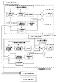
図1は本発明の衝突検出装置を用いたサーボモータの駆動システムを示すブロック図であり、関節軸がN個存在する場合、各関節軸に対して各1個の衝突検出装置を用いたサーボモータの駆動システムで、基本軸制御ブロック20と手首軸制御ブロック21から構成される。
基本軸および手首軸について説明すると、ロボットアームは、一般的な産業用ロボットでは、例えば特開2007−326151号公報に見られるような6軸で構成されており、ロボットアームの姿勢を形成するS軸、L軸、U軸が基本軸と呼ばれ、ロボットアーム先端の姿勢を形成するR軸、B軸、T軸が手首軸と呼ばれている。
図において1は産業用ロボットが適正に動作するために求められた指令位置を出力する指令位置発生装置である。2は指令位置発生装置からの位置指令に対して比例制御をし、速度に対して比例積分制御して、トルク指令を指令する制御部である。3は制御部2が供給する電流により回転するサーボモータ、4はサーボモータ3によって駆動される制御対象のロボットアームである。5はサーボモータの位置を検出するエンコーダであり,6は制御部2のトルク指令とサーボモータ3に設けられたエンコーダ5の回転信号を受けてロボットアーム4が受ける外乱を推定する衝突検出装置、7は衝突検出装置監視部である。衝突検出装置6は、サーボモータ3のモータトルクと回転位置からロボットアーム4に作用する外乱を推定する外乱推定オブザーバを備えている。衝突検出装置監視部7では、この推定された外乱トルクが規定値以上になったとき、衝突が生じているものと判断するようにしている。衝突検出装置監視部7で衝突と判断されると、停止方法選択処理15で、ロボットを停止するための手段を選択し、その後、ロボットはその選択方法に従い、ロボット停止処理9で停止することとなる。
FIG. 1 is a block diagram showing a servo motor drive system using a collision detection device of the present invention. When N joint axes exist, a servo using one collision detection device for each joint axis. The motor drive system includes a basic axis control block 20 and a wrist axis control block 21.
The basic axis and wrist axis will be described. In a general industrial robot, the robot arm is configured with six axes as disclosed in, for example, Japanese Patent Application Laid-Open No. 2007-326151, and forms the posture of the robot arm. The axis, L axis, and U axis are called basic axes, and the R axis, B axis, and T axis that form the posture of the tip of the robot arm are called wrist axes.
In the figure,
以下に、図1および図2を用いて停止選択処理について詳しく説明する。衝突検出装置6では制御部2のトルク指令とサーボモータ3に設けられたエンコーダ5の回転信号を受けてロボットアーム4が受ける外乱を外乱推定オブザーバにより推定する。推定した外乱と、予め設定しておいた規定値を衝突検出装置監視部7で比較する。関節軸がN個存在する場合、N関節軸全ての軸で外乱が規定値以下であれば、ロボットは指令位置発生装置1から出力された指令に従い動作する。衝突検出装置監視部7で規定値以上となった関節軸が1関節でもあれば、衝突と判断され、S2の処理にすすむ。
Hereinafter, the stop selection process will be described in detail with reference to FIGS. 1 and 2. The collision detection device 6 receives a torque command from the
衝突検出装置監視部7で衝突と判断すると、先ず衝突を検出した軸により、S2のステップで、ロボットを停止する方法を分別する。衝突検出装置監視部7で衝突と判断された関節が基本軸の場合、全ての関節軸を引き戻し方法で停止させる。衝突検出装置監視部7で衝突と判断された関節が手首軸の場合は、S3の処理にすすむ。 If the collision detection device monitoring unit 7 determines that a collision has occurred, first, the method of stopping the robot is classified in step S2 based on the axis where the collision is detected. When the joint determined to be a collision by the collision detector monitoring unit 7 is a basic axis, all the joint axes are stopped by a pullback method. When the joint determined to be a collision by the collision detection device monitoring unit 7 is the wrist shaft, the process proceeds to S3.
S3では、衝突を検出した軸の衝突時のモータ回転方向と衝突によりサーボモータに作用するトルク(=衝突トルク)が発生する方向を比較し、モータ回転方向と衝突トルクの方向が逆の場合は、S4に進む。衝突トルクの方向は、衝突検出装置6で推定した外乱の符号により判断する。 In S3, the motor rotation direction at the time of collision of the shaft that detected the collision is compared with the direction in which the torque (= collision torque) acting on the servo motor is generated by the collision, and if the motor rotation direction and the direction of the collision torque are opposite , Go to S4. The direction of the collision torque is determined by the sign of the disturbance estimated by the collision detection device 6.
衝突検出軸が手首軸で、且つ、モータ回転方向と衝突トルクの方向が同じ場合、手首軸に関しては柔軟停止処理により手首軸を停止させ、基本軸に関しては即停止処理により、基本軸を停止させる。 If the collision detection axis is the wrist axis and the motor rotation direction and the collision torque direction are the same, the wrist axis is stopped by the flexible stop process for the wrist axis, and the basic axis is stopped by the immediate stop process for the basic axis. .
衝突検出軸が手首軸で、且つ、モータ回転方向と衝突トルクの方向が逆の場合、S4に進む。S4では、衝突を検出した手首軸の衝突時のサーボモータの回転速度と、予め設定した速度規定値とを比較する。手首軸の衝突時のサーボモータの回転速度が、規定値以上となれば、基本軸、手首軸、全ての関節軸を引き戻し処理によりロボットを停止させる。 If the collision detection axis is the wrist axis and the motor rotation direction and the collision torque direction are opposite, the process proceeds to S4. In S4, the rotation speed of the servo motor at the time of the collision of the wrist shaft that detected the collision is compared with a preset speed regulation value. If the rotation speed of the servo motor at the time of the wrist axis collision is equal to or higher than the specified value, the robot is stopped by pulling back the basic axis, wrist axis, and all joint axes.
衝突検出軸が手首軸で、且つ、モータ回転方向と衝突トルクの方向が逆、且つ、手首軸の衝突時のサーボモータの回転速度が規定値以下となれば、手首軸に関しては柔軟停止処により手首軸を停止させ、基本軸に関しては即停止処理により、基本軸を停止させる。 If the collision detection axis is the wrist axis, the motor rotation direction is opposite to the direction of the collision torque, and the rotation speed of the servo motor at the time of the wrist axis collision is less than the specified value, the wrist axis is subjected to a flexible stop process. The wrist axis is stopped, and the basic axis is stopped by an immediate stop process for the basic axis.
上記したように、衝突を検出した軸、衝突直前のサーボモータの回転方向、衝突トルクの方向、サーボモータの回転速度によりロボット停止方法を切り換える。以下に引き戻し停止、柔軟停止、即停止処理について詳しく説明する。 As described above, the robot stop method is switched according to the axis where the collision is detected, the rotation direction of the servo motor immediately before the collision, the direction of the collision torque, and the rotation speed of the servo motor. The pullback stop, flexible stop, and immediate stop process will be described in detail below.
先ずは、図1を用いて引き戻し停止処理について説明する。指令位置発生装置1により産業用ロボットが適正に動作するために求められた各駆動軸の指令位置を出力され、制御部2により指令位置発生装置からの位置指令に対して比例制御をし、速度に対して比例積分制御してトルク指令を指令し、サーボモータ3により制御部2が供給する電流により回転し、ロボットアーム4が動作する。位置記憶バッファ8によりエンコーダ5から読み込まれたサーボモータ3の現在位置を記憶され、衝突検出器6によりロボットアーム4が受ける外乱を推定し、その推定した外乱と規定値を衝突検出装置監視部7で比較し、衝突検出装置監視部で規定値以上となった関節軸が1関節でもあれば、衝突と判断される。衝突と判断された関節が基本軸の場合、停止方法選択処理15で引戻し処理が選択され、ロボット停止処理9によってスイッチ12がクローズされ、引戻しを実行可能状態となり、ロボットに存在する全ての関節軸を引き戻し停止処理で停止させる。もしくは,衝突検出軸が手首軸で、且つ、モータ回転方向と衝突トルクの方向が逆の場合、且つ、手首軸の衝突時のサーボモータの回転速度が、規定値以上の場合、停止方法選択処理15で引戻し処理が選択され、ロボット停止処理9によってスイッチ12がクローズされ、引戻しを実行可能状態となり、基本軸、手首軸、全ての関節軸を引き戻し停止処理により停止させる。
First, the pullback stop process will be described with reference to FIG. The command
図1の停止方法選択処理15にて引き戻し停止処理が選択されると、位置記憶バッファ8に記憶された位置データに基づき、引き戻し位置と引き戻し速度を決定する。引き戻し位置は、記憶バッファに記録されたデータの中で一番古い位置データに設定される。記憶バッファには予め設定されたM個の位置データが格納されているので、一番古いデータは記憶バッファにあるデータの中で衝突した障害物から一番離れた位置となる。
引き戻し位置をθ1、衝突検出時のサーボモータk3の位置をθ2とすると、引き戻し距離θは式1で表される。
θ=θ1-θ2 (1)
When the pullback stop process is selected in the stop method selection process 15 of FIG. 1, the pullback position and the pullback speed are determined based on the position data stored in the position storage buffer 8. The pullback position is set to the oldest position data among the data recorded in the storage buffer. Since the M position data set in advance is stored in the storage buffer, the oldest data is the position farthest from the colliding obstacle in the data in the storage buffer.
Assuming that the pullback position is θ1 and the position of the servo motor k3 at the time of collision detection is θ2, the pullback distance θ is expressed by
θ = θ1-θ2 (1)
位置記憶バッファには同じ時間の間隔で記録されており,その周期をTとする。引き戻し速度Vは、引き戻し量θ、位置記憶バッファに記憶する周期T、位置記憶バッファに記憶するデータ数Mを用いて式2で表される。
V=θ/(T*M) (2)
The position storage buffer is recorded at the same time interval, and its cycle is T. The pullback speed V is expressed by
V = θ / (T * M) (2)
上式を用いて引き戻し速度を決定することにより、衝突直前のサーボモータの回転速度が速いときは、引き戻し速度は速く、かつ引き戻し量は長くなり、回転速度が遅いときは引き戻し速度は遅く、かつ引き戻し量は短くなる。 By determining the retraction speed using the above equation, when the rotation speed of the servo motor immediately before the collision is fast, the retraction speed is fast and the retraction amount is long, and when the rotation speed is slow, the retraction speed is slow, and The pullback amount is shortened.
衝突検出時のサーボモータ3の位置θ2と、引き戻し速度Vを指令位置変更装置10に対して出力する。指令位置変更装置10は、位置記憶バッファ8から衝突検出時のサーボモータ3の位置θ2と、引き戻し速度Vが入力されると、次式により,指令位置θrを求め、指令位置発生装置1へ出力する。
θr =θ2+ (V*Tr *I) (I=1、2…、T*M/Tr) (3)
The position θ2 of the servo motor 3 at the time of collision detection and the pullback speed V are output to the command position changing device 10. When the position θ2 of the servo motor 3 at the time of collision detection and the pullback speed V are input from the position memory buffer 8, the command position changing device 10 obtains the command position θr by the following equation and outputs it to the
θr = θ2 + (V * Tr * I) (I = 1, 2,..., T * M / Tr) (3)
ここでTrは位置指令の更新周期である。指令位置変更装置10は数3により、位置指令の更新周期Tr 毎にIを1からT*M/Trまで1づつ増やし、指令位置θrを求め、指令位置発生装置1へ出力する。位置指令の更新回数がT*M/Trの時、 指令位置θr はθ1と一致する。位置指令をθ2からθ1に向かって更新することにより、サーボモータには衝突直前の逆方向のトルクが発生し、その逆方向のトルクによりロボットは障害物から離れる方向に位置制御されることとなる。衝突直前のサーボモータの回転速度が速いときは、引き戻し速度は速く、かつ引き戻し量は長くなり、回転速度が遅いときは引き戻し速度は遅く、かつ引き戻し量は短くなる。
Here, Tr is a position command update cycle. The command position changing device 10 increases I by 1 from 1 to T * M / Tr for each position command update cycle Tr by Equation 3, obtains the command position θr, and outputs it to the
衝突時のサーボモータの回転速度が速ければ、ロボットの障害物への行き過ぎ量は長くなり、ロボットを確実に障害物から引き戻すためには、引き戻し量を長くする必要がある。また、ロボットと障害物の受けるダメージは衝突時の速度に比例することとなるので、速度に比例して引き戻す速度を速くする必要がある。 If the rotation speed of the servo motor at the time of the collision is high, the amount of overtravel to the obstacle of the robot becomes long, and in order to reliably pull the robot back from the obstacle, it is necessary to lengthen the pullback amount. Further, since the damage received by the robot and the obstacle is proportional to the speed at the time of the collision, it is necessary to increase the speed of pulling back in proportion to the speed.
ロボットと障害物の受けるダメージは衝突時の速度に比例することとなる。本実施例を適用すれば衝突検出後、引き戻し速度を衝突前のサーボモータの回転速度に比例して決定するので、ロボットと障害物の受けるダメージを最小限に抑えることができる。また、衝突前のサーボモータの回転速度に比例して引き戻し量は長くなるので、ロボットを確実に障害物から引き戻すことができる。 The damage received by the robot and the obstacle is proportional to the speed at the time of collision. If this embodiment is applied, after the collision is detected, the pullback speed is determined in proportion to the rotational speed of the servo motor before the collision, so that damage to the robot and the obstacle can be minimized. In addition, since the pullback amount becomes longer in proportion to the rotation speed of the servo motor before the collision, the robot can be reliably pulled back from the obstacle.
衝突検出軸が手首軸ではなく基本軸の場合、モータ回転方向と衝突トルクの方向によらず、全軸引き戻し停止とする。モータ回転方向と衝突トルクが同じ場合、基本軸を柔軟制御に切り換え衝突力に倣って動作することとなり、衝突トルクを緩和することができるが、基本軸は手首軸と比べて慣性が大きく、大きな慣性力を持った基本軸を柔軟停止とした場合、ロボットは衝突検出後大きく動作することとなり、再衝突の危険がある。そこで、基本軸で検出した場合、モータ回転方向と衝突トルクの方向によらず、全軸引き戻し停止とすることにより、再衝突の危険性は柔軟制御と比べ低く、より安全である。また、引き戻し停止処理では、引き戻す位置はロボットの軌跡上に引き戻すため、引き戻し停止処理後、再プレイバックした場合、ロボットはティーチング時の指令軌跡上を動作することとなり、再衝突することはない。 When the collision detection axis is not a wrist axis but a basic axis, all axes are pulled back regardless of the direction of motor rotation and the direction of collision torque. If the motor rotation direction and the collision torque are the same, the basic axis is switched to flexible control and the operation follows the collision force.The collision torque can be mitigated, but the basic axis has a larger inertia than the wrist axis. If the basic axis with inertial force is set to a flexible stop, the robot will move greatly after the collision is detected, and there is a risk of re-collision. Therefore, when detecting with the basic shaft, the risk of re-collision is lower and safer than the flexible control by stopping pulling back on all shafts regardless of the direction of motor rotation and the direction of collision torque. In the pull back stop process, the pull back position is pulled back on the robot trajectory. Therefore, if the replay is performed after the pull back stop process, the robot operates on the command trajectory during teaching and does not collide again.
衝突検出軸が手首軸で、且つ、モータ回転方向と衝突トルクの方向が逆の場合、且つ、手首軸の衝突時のサーボモータの回転速度が規定値以上の場合、手首軸の慣性トルクが大きいので、モータ回転と逆方向のトルクをモータで発生させることによりモータ回転速度を減速し、衝突エネルギーを緩和し、ロボットと障害物の受けるダメージを最小限に抑えることができる。また、引き戻し停止処理では、引き戻す位置はロボットの軌跡上に引き戻すため、引き戻し停止処理後、再プレイバックした場合、ロボットはティーチング時の指令軌跡上を動作することとなり、再衝突することはない。 If the collision detection axis is the wrist axis and the motor rotation direction and the direction of the collision torque are opposite, and if the rotation speed of the servo motor at the time of the wrist axis collision is greater than the specified value, the inertia torque of the wrist axis is large Therefore, by generating a torque in the opposite direction to the motor rotation, the motor rotation speed can be reduced, the collision energy can be reduced, and damage to the robot and the obstacle can be minimized. In the pull back stop process, the pull back position is pulled back on the robot trajectory. Therefore, if the replay is performed after the pull back stop process, the robot operates on the command trajectory during teaching and does not collide again.
次に、手首軸柔軟停止処理、基本軸即停止処理について詳しく説明する。衝突検出軸が手首軸で、且つ、モータ回転方向と衝突トルクの方向が同じ場合、柔軟停止処により手首軸を停止させ、即停止処理により、基本軸を停止させる。もしくは,衝突検出軸が手首軸で、且つ、モータ回転方向と衝突トルクの方向が逆の場合、且つ、手首軸の衝突時のサーボモータの回転速度が、規定値以下の場合、柔軟停止処理により手首軸を停止させ、即停止処理により、基本軸を停止させる。 Next, the wrist axis soft stop process and the basic axis immediate stop process will be described in detail. When the collision detection axis is the wrist axis and the motor rotation direction is the same as the direction of the collision torque, the wrist axis is stopped by the flexible stop process, and the basic axis is stopped by the immediate stop process. Or, if the collision detection axis is the wrist axis, the motor rotation direction and the direction of the collision torque are opposite, and the rotation speed of the servo motor at the time of the wrist axis collision is less than the specified value, the flexible stop process Stop wrist axis and stop basic axis by immediate stop process.
図1を用いて柔軟停止処理が選択された場合の手首軸の制御系を説明する。衝突検出器6により、ロボットアーム4が受ける外乱を推定し、その推定した外乱と規定値を衝突検出装置監視部7で比較し、衝突検出装置監視部で規定値以上となった関節軸が1関節でもあれば、衝突と判断される。停止方法選択処理15にて柔軟停止処理が選択されると、衝突検出後ただちに、制御手段内で、スイッチ13をオープンにして、強制的に制御部2からのトルク指令値を0にする。このままだと重力の作用するアームの場合、アームが落下するため、スイッチ14をクローズし、サーボモータへのトルク指令値に重力補償値を加算する。重力補償値はロボットアームの姿勢および重量パラメータから計算するか、または計測で予め求めておく。これにより、衝突後、手首軸は衝突時に受ける衝突トルクに対して柔軟に倣う状態になる。また、衝突検出時、スイッチ13をオープン、スイッチ14をクローズにすると同時に衝突を検出した瞬間の指令位置発生装置からの位置指令を復帰位置記憶装置11に出力する。
The wrist axis control system when the flexible stop process is selected will be described with reference to FIG. The collision detector 6 estimates the disturbance received by the robot arm 4, compares the estimated disturbance with a specified value by the collision detection device monitoring unit 7, and the joint axis that exceeds the specified value by the collision detection device monitoring unit is 1 If it is also a joint, it is judged as a collision. When the flexible stop process is selected in the stop method selection process 15, immediately after the collision is detected, the switch 13 is opened in the control means to forcibly set the torque command value from the
また、図1を用いて即時停止処理が選択された場合の基本軸の制御系を説明する。停止方法選択処理15により即時停止処理が選択されると、ロボット停止処理9によりスイッチ12をクローズ、即時停止処理を実行可能状態とする。位置記憶バッファ8にて、エンコーダ5から読み込まれたサーボモータ3の現在位置を記憶する。衝突検出器6により、ロボットアーム4が受ける外乱を推定し、その推定した外乱と規定値を衝突検出装置監視部7で比較し、衝突検出装置監視部で規定値以上となった関節軸が1関節でもあれば、衝突と判断される。停止方法選択処理にて即時停止処理が選択されると、位置記憶バッファに記憶された位置データに基づき、停止位置を決定する。衝突を検出した瞬間の位置記憶バッファ8に記録されたデータの中で一番新しい位置データを停止位置とする。記憶バッファ8には予め設定されたM個の位置データが格納されているので、一番新しいデータは衝突を検出した位置となる。位置記憶バッファ8に記録されたデータの中で一番新しい位置データを指令位置変更装置10に対して出力する。サーボモータ3には衝突直前の逆方向のトルクが発生し、その逆方向のトルクによりロボットアーム4は衝突検出時の位置に位置制御されることとなる。また、衝突を検出した瞬間の指令位置発生装置からの位置指令を復帰位置記憶装置11に出力する。 The basic axis control system when the immediate stop process is selected will be described with reference to FIG. When the immediate stop process is selected by the stop method selection process 15, the switch 12 is closed by the robot stop process 9 to make the immediate stop process executable. The position storage buffer 8 stores the current position of the servo motor 3 read from the encoder 5. The collision detector 6 estimates the disturbance received by the robot arm 4, compares the estimated disturbance with a specified value by the collision detection device monitoring unit 7, and the joint axis that exceeds the specified value by the collision detection device monitoring unit is 1 If it is also a joint, it is judged as a collision. When the immediate stop process is selected in the stop method selection process, the stop position is determined based on the position data stored in the position storage buffer. The newest position data among the data recorded in the position storage buffer 8 at the moment when the collision is detected is set as the stop position. Since the storage buffer 8 stores M position data set in advance, the newest data is a position where a collision is detected. The latest position data among the data recorded in the position storage buffer 8 is output to the command position changing device 10. The servo motor 3 generates reverse torque immediately before the collision, and the position of the robot arm 4 is controlled to the position at the time of collision detection by the reverse torque. The position command from the command position generator at the moment when the collision is detected is output to the return position storage device 11.
停止方法選択処理15にて手首軸柔軟停止処理、基本軸即停止処理が選択されるのは、衝突検出軸が手首軸で、且つ、モータ回転方向と衝突トルクの方向が同じ場合、もしくは,衝突検出軸が手首軸で、且つ、モータ回転方向と衝突トルクの方向が逆の場合、且つ、手首軸の衝突時のサーボモータの回転速度が、規定値以下の場合である。衝突検出軸が手首軸で、且つ、モータ回転方向と衝突トルクの方向が同じ場合、手首軸を柔軟停止とすることにより、手首軸は衝突力に倣って動作することとなり、衝突トルクを緩和することができる。また、この際、基本軸についても柔軟停止をすることが考えられるが、基本軸は手首軸と比べて慣性が大きく、大きな慣性力を持った基本軸を柔軟停止とした場合、ロボットは衝突検出後大きく動作することとなり、再衝突の危険がある。よって、基本軸については柔軟停止ではなく、衝突を検出した位置に停止させる即停止処理とする。 The wrist axis soft stop process and the basic axis immediate stop process are selected in the stop method selection process 15 when the collision detection axis is the wrist axis and the motor rotation direction and the collision torque direction are the same, or the collision This is the case where the detection shaft is the wrist shaft, the motor rotation direction is opposite to the direction of the collision torque, and the rotation speed of the servo motor at the time of the wrist shaft collision is less than the specified value. If the collision detection axis is the wrist axis and the direction of the motor rotation and the direction of the collision torque are the same, the wrist axis will move according to the collision force by softening the wrist axis, reducing the collision torque. be able to. At this time, it is conceivable to make a flexible stop for the basic axis as well. However, the basic axis has a larger inertia than the wrist axis, and if the basic axis with a large inertia force is set to the flexible stop, the robot detects the collision. Later, it will move greatly and there is a danger of re-collision. Therefore, the basic axis is not a flexible stop, but an immediate stop process for stopping at the position where the collision is detected.
手首軸柔軟停止処理、基本軸即停止処理後、手首軸に関しては制御不能状態となるので、指令軌跡上から外れることとなり,ロボットアーム停止後、再プレイバックをした場合、ロボットはティーチング時とは違う軌跡上を移動することとなり、障害物に衝突する可能性がある。そこで、再プレイバック時の衝突を避けるため、再プレイバック要求があった場合、復帰位置記憶装置11に記憶された位置に低速で全軸戻してから、プレイバック動作に入ることとする。復帰位置記憶装置11に記憶された位置は、指令軌跡上の位置であり、障害物に再衝突する可能性は低く、安全である。また低速で指令軌跡上に戻してからプレイバック動作に入るため、指令軌跡上に戻るまでに、再衝突したとしても、ロボットアーム、及び障害物に与える機械的ダメージを最小限に抑えることが出来る。 After the wrist axis flexible stop process and the basic axis immediate stop process, the wrist axis becomes uncontrollable, so it will be off the command path. If the robot arm is stopped and replayed, the robot will It will move on a different trajectory and may collide with an obstacle. Therefore, in order to avoid a collision at the time of replayback, when there is a replayback request, all the axes are returned to the position stored in the return position storage device 11 at a low speed, and then the playback operation is started. The position stored in the return position storage device 11 is a position on the command trajectory, and the possibility of re-collision with an obstacle is low and safe. Also, since the playback operation is started after returning to the command trajectory at a low speed, mechanical damage to the robot arm and obstacles can be minimized even if a collision occurs again before returning to the command trajectory. .
衝突検出軸が手首軸、且つ、モータ回転方向と衝突トルクの方向が逆の場合、且つ、手首軸の衝突時のサーボモータの回転速度が規定値以下の場合、手首軸を柔軟停止、基本軸を即停止させる。サーボモータの回転速度の規定値は、実機により予め決めておく。衝突検出軸が手首軸で、且つ、手首軸の衝突時のサーボモータの回転速度が規定値以下の場合、手首軸の慣性は小さいので、ロボット及び障害物に与える機械的ダメージは小さい。よって、引き戻し動作をさせるより、手首軸を柔軟停止とすることにより、手首軸は外力に倣って動作することとなり、衝突で生じた減速機等の歪みを素早く解消することが出来る。また、この場合についても再プレイバック要求があった場合、復帰位置記憶装置11に記憶された位置に低速で全軸戻してから、プレイバック動作に入ることとする。復帰位置記憶装置11に記憶された位置は、指令軌跡上の位置であり、障害物に再衝突する可能性は低く、安全である。また低速で指令軌跡上に戻してからプレイバック動作に入るため、指令軌跡上に戻るまでに、再衝突したとしても、ロボットアーム及び障害物に与える機械的ダメージを最小限に抑えることが出来る。 If the collision detection axis is the wrist axis and the motor rotation direction and the direction of the collision torque are opposite, and the rotation speed of the servo motor at the time of the wrist axis collision is less than the specified value, the wrist axis is flexibly stopped. Stop immediately. The specified value of the rotation speed of the servo motor is determined in advance by the actual machine. When the collision detection axis is the wrist axis and the rotation speed of the servo motor at the time of the wrist axis collision is equal to or lower than the specified value, the inertia of the wrist axis is small, so that the mechanical damage to the robot and the obstacle is small. Therefore, by setting the wrist shaft to a flexible stop rather than performing a pull-back operation, the wrist shaft operates following the external force, and the distortion of the speed reducer and the like caused by the collision can be quickly eliminated. Also in this case, when there is a replay request, the playback operation is started after returning all axes to the position stored in the return position storage device 11 at a low speed. The position stored in the return position storage device 11 is a position on the command trajectory, and the possibility of re-collision with an obstacle is low and safe. Further, since the playback operation is started after returning to the command trajectory at a low speed, even if a collision occurs again before returning to the command trajectory, mechanical damage to the robot arm and the obstacle can be minimized.
1 指令発生装置
2 制御部
3 サーボモータ
4 ロボットアーム
5 エンコーダ
6 衝突検出装置
7 衝突検出装置監視部
8 位置記憶バッファ
9 ロボット停止処理
10 指令位置変更装置
11 復帰位置記憶装置
12 スイッチ
13 スイッチ
14 スイッチ
15 停止方法選択処理
20 基本軸制御ブロック
21 手首軸制御ブロック
DESCRIPTION OF
Claims (11)
前記衝突検出装置からの前記情報をもとに複数の停止方法のうちから一つの停止方法を選択する停止方法選択処理部を備え、
前記停止方法選択処理部は、前記衝突検出装置で衝突を検出した軸が前記ロボットアームの基本軸の場合、前記ロボットアームの全軸を引き戻して停止させる停止方法を選択する一方、前記衝突検出装置で衝突を検出した軸が前記ロボットアームの手首軸の場合、柔軟停止処理により前記手首軸を停止させつつ即停止処理により前記基本軸を停止させる停止方法と、前記全軸を引き戻して停止させる停止方法とのいずれかを選択することを特徴とするロボットシステム。 In a robot system that includes a robot arm driven by a motor and a collision detection device that detects that the robot arm collides with an obstacle, and controls the robot arm based on information from the collision detection device,
A stop method selection processing unit that selects one stop method from a plurality of stop methods based on the information from the collision detection device ;
The stop method selection processing unit selects a stop method for pulling back and stopping all axes of the robot arm when the axis detected by the collision detection device is a basic axis of the robot arm, while the collision detection device in case the axis of the detecting collision of the wrist axis of the robot arm, a stopping method for stopping the pre Kimoto present axis by immediate stop processing while stopping the previous Kite neck axis by flexible stopping process, the pre-Symbol all axes It pulled back robot system and wherein the benzalkonium select one of the stop method for stopping.
複数の停止方法のうちから一つの停止方法を選択する停止方法選択処理部により、衝突検出軸が前記ロボットアームの基本軸の場合、前記ロボットアームの全軸を引き戻して停止させる停止方法を選択する一方、衝突検出軸が前記ロボットアームの手首軸の場合、柔軟停止処理により前記手首軸を停止させつつ即停止処理により前記基本軸を停止させる停止方法と、前記全軸を引き戻して停止させる停止方法とのいずれかを選択することを特徴とするロボットシステムの制御方法。 In the control method of the robot system when detecting the collision of the robot arm in the motor control,
When a collision detection axis is a basic axis of the robot arm, a stop method for pulling back and stopping all axes of the robot arm is selected by a stop method selection processing unit that selects one of the plurality of stop methods. On the other hand, pulling back when collision detection axis of the wrist axis of the robot arm, a stopping method for stopping the pre Kimoto present axis by immediate stop processing while stopping the previous Kite neck axis by flexible stopping process, the pre-Symbol all axes control method of a robot system according to claim you to select one of the stopping process to stop Te.
Priority Applications (3)
| Application Number | Priority Date | Filing Date | Title |
|---|---|---|---|
| JP2008314492A JP5375062B2 (en) | 2008-12-10 | 2008-12-10 | Robot system and control method |
| US12/538,167 US8423189B2 (en) | 2008-12-10 | 2009-08-10 | Robot system and control method |
| EP09168310A EP2199037B1 (en) | 2008-12-10 | 2009-08-20 | Robot system and control method |
Applications Claiming Priority (1)
| Application Number | Priority Date | Filing Date | Title |
|---|---|---|---|
| JP2008314492A JP5375062B2 (en) | 2008-12-10 | 2008-12-10 | Robot system and control method |
Publications (3)
| Publication Number | Publication Date |
|---|---|
| JP2010137312A JP2010137312A (en) | 2010-06-24 |
| JP2010137312A5 JP2010137312A5 (en) | 2011-09-01 |
| JP5375062B2 true JP5375062B2 (en) | 2013-12-25 |
Family
ID=42078820
Family Applications (1)
| Application Number | Title | Priority Date | Filing Date |
|---|---|---|---|
| JP2008314492A Active JP5375062B2 (en) | 2008-12-10 | 2008-12-10 | Robot system and control method |
Country Status (3)
| Country | Link |
|---|---|
| US (1) | US8423189B2 (en) |
| EP (1) | EP2199037B1 (en) |
| JP (1) | JP5375062B2 (en) |
Cited By (1)
| Publication number | Priority date | Publication date | Assignee | Title |
|---|---|---|---|---|
| US11040449B2 (en) | 2017-12-27 | 2021-06-22 | Hanwha Co., Ltd. | Robot control system and method of controlling a robot |
Families Citing this family (30)
| Publication number | Priority date | Publication date | Assignee | Title |
|---|---|---|---|---|
| DE102010033768A1 (en) * | 2010-08-09 | 2012-02-09 | Dürr Systems GmbH | Control system and control method for a robot |
| JP5365595B2 (en) * | 2010-09-15 | 2013-12-11 | 株式会社安川電機 | Speed reducer abnormality determination method, abnormality determination apparatus, robot, and robot system |
| DE102013000250A1 (en) | 2013-01-09 | 2014-07-10 | Kuka Laboratories Gmbh | Configurable security monitoring for a robot arrangement |
| DE102013013875A1 (en) | 2013-08-20 | 2015-02-26 | Kuka Laboratories Gmbh | Method for controlling a robot |
| DE102013016019B3 (en) * | 2013-09-25 | 2015-03-19 | Festo Ag & Co. Kg | Method for operating a multi-unit manipulator |
| DE202013105036U1 (en) * | 2013-11-08 | 2015-02-10 | Daimler Ag | detector |
| US9452532B2 (en) * | 2014-01-27 | 2016-09-27 | Panasonic Intellectual Property Management Co., Ltd. | Robot, device and method for controlling robot, and computer-readable non-transitory recording medium |
| JP5926346B2 (en) | 2014-09-25 | 2016-05-25 | ファナック株式会社 | Human cooperation robot system |
| US9676097B1 (en) * | 2014-11-11 | 2017-06-13 | X Development Llc | Systems and methods for robotic device authentication |
| DE102015200355B3 (en) * | 2015-01-02 | 2016-01-28 | Siemens Aktiengesellschaft | A medical robotic device with collision detection and method for collision detection of a medical robotic device |
| JP5937706B1 (en) * | 2015-01-21 | 2016-06-22 | ファナック株式会社 | Robot control apparatus and robot system for controlling robot based on external force applied to robot |
| DE102015017296B3 (en) | 2015-08-14 | 2021-10-07 | Franka Emika Gmbh | Robotic system |
| JP6794194B2 (en) * | 2015-09-17 | 2020-12-02 | キヤノン株式会社 | Manufacturing methods for robotic devices, control methods, programs, recording media and articles |
| DE102015012962A1 (en) | 2015-10-08 | 2017-04-13 | Sami Haddadin | robot system |
| DE102015012959B4 (en) | 2015-10-08 | 2019-01-17 | Franka Emika Gmbh | Robot system and method for controlling a robot system |
| DE102015012961B4 (en) | 2015-10-08 | 2022-05-05 | Kastanienbaum GmbH | robotic system |
| KR101734241B1 (en) * | 2015-12-10 | 2017-05-11 | 현대자동차 주식회사 | Trunk lid hinge intellectual loader unit |
| US10082783B2 (en) * | 2015-12-17 | 2018-09-25 | Feng-Tien Chen | Computer numerical control servo drive system |
| JP6733239B2 (en) * | 2016-03-18 | 2020-07-29 | セイコーエプソン株式会社 | Controller and robot system |
| CN107294428A (en) * | 2016-04-08 | 2017-10-24 | 陈丰田 | CNC SERVO CONTROL drive systems |
| DE102016004787B4 (en) | 2016-04-20 | 2023-02-02 | Franka Emika Gmbh | Driving device for a robot and method for its manufacture |
| DE102016004788A1 (en) | 2016-04-20 | 2017-10-26 | Kastanienbaum GmbH | Method for producing a robot and device for carrying out this method |
| DE102016210060A1 (en) * | 2016-06-08 | 2017-12-14 | Kuka Roboter Gmbh | Method for safely stopping a manipulator |
| US9981383B1 (en) * | 2016-08-02 | 2018-05-29 | X Development Llc | Real-time trajectory generation for actuators of a robot to reduce chance of collision with obstacle(s) |
| JP6939104B2 (en) * | 2017-06-09 | 2021-09-22 | セイコーエプソン株式会社 | Control devices, robot systems and robot control methods |
| JP6948164B2 (en) * | 2017-06-12 | 2021-10-13 | 日立Geニュークリア・エナジー株式会社 | Work robot arm attitude control system and method |
| WO2019010612A1 (en) * | 2017-07-10 | 2019-01-17 | 深圳市艾唯尔科技有限公司 | Robot joint anti-collision protection system and method based on sensing fusion technology |
| CN112060072B (en) * | 2019-06-11 | 2023-06-20 | 华邦电子股份有限公司 | Collaborative robot control system and method |
| US11628568B2 (en) | 2020-12-28 | 2023-04-18 | Industrial Technology Research Institute | Cooperative robotic arm system and homing method thereof |
| CN114872034A (en) * | 2022-06-16 | 2022-08-09 | 北京市商汤科技开发有限公司 | Mechanical arm driving structure, arm type robot and driving method |
Family Cites Families (25)
| Publication number | Priority date | Publication date | Assignee | Title |
|---|---|---|---|---|
| JPS57168306A (en) * | 1981-04-08 | 1982-10-16 | Daihen Corp | Controlling method of industrial robot |
| JPH0619657B2 (en) * | 1983-12-09 | 1994-03-16 | 株式会社日立製作所 | Robot control method and apparatus |
| JPS6158002A (en) * | 1984-08-28 | 1986-03-25 | Toyota Motor Corp | Controller of robot |
| JPH06102315B2 (en) * | 1985-12-16 | 1994-12-14 | 株式会社安川電機 | Shock absorption method |
| JPH033687A (en) * | 1989-05-31 | 1991-01-09 | Fanuc Ltd | Method of preventing collision damage of body driven by servo motor |
| JP2633696B2 (en) * | 1989-09-20 | 1997-07-23 | 本田技研工業株式会社 | Robot control system |
| JP2665984B2 (en) * | 1989-12-26 | 1997-10-22 | ファナック株式会社 | Collision detection method using disturbance estimation observer |
| US5304906A (en) * | 1989-12-26 | 1994-04-19 | Fanuc Ltd. | Collision detecting method using an observer |
| JPH06131050A (en) | 1992-10-20 | 1994-05-13 | Fanuc Ltd | Method for detecting collision of movable part driven by servo motor |
| JPH06245561A (en) * | 1993-02-10 | 1994-09-02 | Fanuc Ltd | Abnormal load detection control method for servo motor |
| JPH08393B2 (en) | 1993-03-26 | 1996-01-10 | 日本電気株式会社 | Robot arm with collision prevention function |
| JP2871993B2 (en) * | 1993-03-31 | 1999-03-17 | 日本電気株式会社 | Servo motor position control device |
| JP3460761B2 (en) * | 1995-09-11 | 2003-10-27 | 株式会社安川電機 | Robot control device |
| JP3327205B2 (en) * | 1998-03-30 | 2002-09-24 | 松下電器産業株式会社 | Robot control method and device |
| JP2000246684A (en) * | 1999-02-26 | 2000-09-12 | Sharp Corp | Arm type robot |
| JP3212571B2 (en) * | 1999-03-26 | 2001-09-25 | ファナック株式会社 | Industrial robot |
| JP2000277039A (en) * | 1999-03-26 | 2000-10-06 | Toshiba Corp | Image display device and manufacture thereof |
| JP3459973B2 (en) * | 1999-10-22 | 2003-10-27 | 川崎重工業株式会社 | Drive control method and drive control device |
| JP2001260061A (en) * | 2000-03-15 | 2001-09-25 | Kawasaki Heavy Ind Ltd | Method for restarting robot |
| JP2007326151A (en) | 2001-10-22 | 2007-12-20 | Yaskawa Electric Corp | Industrial robot |
| JP2003236787A (en) * | 2002-02-18 | 2003-08-26 | Kawasaki Heavy Ind Ltd | Drivingly controlling method and drivingly controlling device |
| US6892512B2 (en) * | 2002-08-07 | 2005-05-17 | Medco Health Solutions, Inc. | Automated prescription filling system/method with automated labeling and packaging system/method automated order consolidation system/method |
| EP2380711A1 (en) * | 2003-07-29 | 2011-10-26 | Panasonic Corporation | Robot arm control method |
| JP2005100143A (en) * | 2003-09-25 | 2005-04-14 | Kobe Steel Ltd | Control method and control device for motor-driven device |
| US20060178775A1 (en) * | 2005-02-04 | 2006-08-10 | George Zhang | Accelerometer to monitor movement of a tool assembly attached to a robot end effector |
-
2008
- 2008-12-10 JP JP2008314492A patent/JP5375062B2/en active Active
-
2009
- 2009-08-10 US US12/538,167 patent/US8423189B2/en active Active
- 2009-08-20 EP EP09168310A patent/EP2199037B1/en active Active
Cited By (1)
| Publication number | Priority date | Publication date | Assignee | Title |
|---|---|---|---|---|
| US11040449B2 (en) | 2017-12-27 | 2021-06-22 | Hanwha Co., Ltd. | Robot control system and method of controlling a robot |
Also Published As
| Publication number | Publication date |
|---|---|
| US8423189B2 (en) | 2013-04-16 |
| EP2199037B1 (en) | 2013-01-23 |
| EP2199037A2 (en) | 2010-06-23 |
| EP2199037A3 (en) | 2011-10-26 |
| US20100145515A1 (en) | 2010-06-10 |
| JP2010137312A (en) | 2010-06-24 |
Similar Documents
| Publication | Publication Date | Title |
|---|---|---|
| JP5375062B2 (en) | Robot system and control method | |
| US9421687B2 (en) | Robot control apparatus and robot control method | |
| US7102311B2 (en) | Drive control method and drive controller | |
| JP3459973B2 (en) | Drive control method and drive control device | |
| JP6472214B2 (en) | Robot apparatus control method and robot apparatus | |
| JP4550849B2 (en) | Mobile robot with arm | |
| US10690558B2 (en) | Robot collision detection method | |
| JP4983812B2 (en) | Robot control method and control apparatus | |
| JP6445150B2 (en) | Method for controlling robot manipulator, computer system, digital recording medium, computer program product, computer program, apparatus and robot | |
| DK2492062T3 (en) | industrial Robot | |
| JP2015226961A (en) | Control device for robot | |
| CN108748144B (en) | Collision recognition method of man-machine cooperation mechanical arm | |
| CN105459113A (en) | Robot controller | |
| JP2010172990A (en) | Apparatus and method for controlling robot | |
| JP5436160B2 (en) | Force control device | |
| JPH1170490A (en) | Collision detecting method for industrial robot | |
| JPH11282540A (en) | Robot control device and method | |
| JP4240517B2 (en) | Servo motor and abnormal load detection control method for articulated robot | |
| JP3327205B2 (en) | Robot control method and device | |
| JPH1110580A (en) | Method and device for controlling driving shaft of industrial robot | |
| JPH01310889A (en) | Controller for industrial robot | |
| EP3520972B1 (en) | Robot controlling method and welding method | |
| JP5299255B2 (en) | Robot controller | |
| JP2016120537A (en) | Manipulator device and drive control program | |
| JP2008253132A (en) | Method of detecting and controlling abnormal load in servo motor and articulated robot |
Legal Events
| Date | Code | Title | Description |
|---|---|---|---|
| A621 | Written request for application examination |
Free format text: JAPANESE INTERMEDIATE CODE: A621 Effective date: 20110607 |
|
| A521 | Written amendment |
Free format text: JAPANESE INTERMEDIATE CODE: A523 Effective date: 20110714 |
|
| RD02 | Notification of acceptance of power of attorney |
Free format text: JAPANESE INTERMEDIATE CODE: A7422 Effective date: 20120216 |
|
| A977 | Report on retrieval |
Free format text: JAPANESE INTERMEDIATE CODE: A971007 Effective date: 20120920 |
|
| A131 | Notification of reasons for refusal |
Free format text: JAPANESE INTERMEDIATE CODE: A131 Effective date: 20121002 |
|
| A521 | Written amendment |
Free format text: JAPANESE INTERMEDIATE CODE: A523 Effective date: 20121115 |
|
| A131 | Notification of reasons for refusal |
Free format text: JAPANESE INTERMEDIATE CODE: A131 Effective date: 20130423 |
|
| A521 | Written amendment |
Free format text: JAPANESE INTERMEDIATE CODE: A523 Effective date: 20130617 |
|
| TRDD | Decision of grant or rejection written | ||
| A01 | Written decision to grant a patent or to grant a registration (utility model) |
Free format text: JAPANESE INTERMEDIATE CODE: A01 Effective date: 20130827 |
|
| A61 | First payment of annual fees (during grant procedure) |
Free format text: JAPANESE INTERMEDIATE CODE: A61 Effective date: 20130909 |
|
| R150 | Certificate of patent or registration of utility model |
Ref document number: 5375062 Country of ref document: JP Free format text: JAPANESE INTERMEDIATE CODE: R150 Free format text: JAPANESE INTERMEDIATE CODE: R150 |