JP5373819B2 - Apparatus for quantifying electrical imbalance and contact detection system incorporating the same - Google Patents
Apparatus for quantifying electrical imbalance and contact detection system incorporating the same Download PDFInfo
- Publication number
- JP5373819B2 JP5373819B2 JP2010541860A JP2010541860A JP5373819B2 JP 5373819 B2 JP5373819 B2 JP 5373819B2 JP 2010541860 A JP2010541860 A JP 2010541860A JP 2010541860 A JP2010541860 A JP 2010541860A JP 5373819 B2 JP5373819 B2 JP 5373819B2
- Authority
- JP
- Japan
- Prior art keywords
- path
- polarization
- detection
- potential
- paths
- Prior art date
- Legal status (The legal status is an assumption and is not a legal conclusion. Google has not performed a legal analysis and makes no representation as to the accuracy of the status listed.)
- Active
Links
Images


Classifications
-
- G—PHYSICS
- G06—COMPUTING; CALCULATING OR COUNTING
- G06F—ELECTRIC DIGITAL DATA PROCESSING
- G06F3/00—Input arrangements for transferring data to be processed into a form capable of being handled by the computer; Output arrangements for transferring data from processing unit to output unit, e.g. interface arrangements
- G06F3/01—Input arrangements or combined input and output arrangements for interaction between user and computer
- G06F3/03—Arrangements for converting the position or the displacement of a member into a coded form
- G06F3/041—Digitisers, e.g. for touch screens or touch pads, characterised by the transducing means
- G06F3/0416—Control or interface arrangements specially adapted for digitisers
- G06F3/04166—Details of scanning methods, e.g. sampling time, grouping of sub areas or time sharing with display driving
-
- G—PHYSICS
- G06—COMPUTING; CALCULATING OR COUNTING
- G06F—ELECTRIC DIGITAL DATA PROCESSING
- G06F3/00—Input arrangements for transferring data to be processed into a form capable of being handled by the computer; Output arrangements for transferring data from processing unit to output unit, e.g. interface arrangements
- G06F3/01—Input arrangements or combined input and output arrangements for interaction between user and computer
- G06F3/03—Arrangements for converting the position or the displacement of a member into a coded form
- G06F3/041—Digitisers, e.g. for touch screens or touch pads, characterised by the transducing means
- G06F3/044—Digitisers, e.g. for touch screens or touch pads, characterised by the transducing means by capacitive means
-
- G—PHYSICS
- G06—COMPUTING; CALCULATING OR COUNTING
- G06F—ELECTRIC DIGITAL DATA PROCESSING
- G06F3/00—Input arrangements for transferring data to be processed into a form capable of being handled by the computer; Output arrangements for transferring data from processing unit to output unit, e.g. interface arrangements
- G06F3/01—Input arrangements or combined input and output arrangements for interaction between user and computer
- G06F3/03—Arrangements for converting the position or the displacement of a member into a coded form
- G06F3/033—Pointing devices displaced or positioned by the user, e.g. mice, trackballs, pens or joysticks; Accessories therefor
- G06F3/0354—Pointing devices displaced or positioned by the user, e.g. mice, trackballs, pens or joysticks; Accessories therefor with detection of 2D relative movements between the device, or an operating part thereof, and a plane or surface, e.g. 2D mice, trackballs, pens or pucks
-
- H—ELECTRICITY
- H03—ELECTRONIC CIRCUITRY
- H03K—PULSE TECHNIQUE
- H03K17/00—Electronic switching or gating, i.e. not by contact-making and –breaking
- H03K17/94—Electronic switching or gating, i.e. not by contact-making and –breaking characterised by the way in which the control signals are generated
- H03K17/96—Touch switches
- H03K17/962—Capacitive touch switches
- H03K17/9622—Capacitive touch switches using a plurality of detectors, e.g. keyboard
-
- H—ELECTRICITY
- H03—ELECTRONIC CIRCUITRY
- H03K—PULSE TECHNIQUE
- H03K2217/00—Indexing scheme related to electronic switching or gating, i.e. not by contact-making or -breaking covered by H03K17/00
- H03K2217/94—Indexing scheme related to electronic switching or gating, i.e. not by contact-making or -breaking covered by H03K17/00 characterised by the way in which the control signal is generated
- H03K2217/96—Touch switches
- H03K2217/9607—Capacitive touch switches
- H03K2217/96071—Capacitive touch switches characterised by the detection principle
- H03K2217/960725—Charge-transfer
Landscapes
- Engineering & Computer Science (AREA)
- General Engineering & Computer Science (AREA)
- Theoretical Computer Science (AREA)
- Human Computer Interaction (AREA)
- Physics & Mathematics (AREA)
- General Physics & Mathematics (AREA)
- Position Input By Displaying (AREA)
- Electronic Switches (AREA)
- Measurement Of Length, Angles, Or The Like Using Electric Or Magnetic Means (AREA)
Abstract
Description
本発明は、特に接触検出システムのための電気経路間の不均衡を検出して定量化するための装置に関する。
本発明は、従って、特に、タッチパッドという一般的な用語で公知の装置、すなわち、接触又は物体の存在、特に、パッド、すなわち、表面の下に様々な規則的なパターン(線、アレイ、ダイヤモンド形の模様、蜂の巣、螺旋回転、迷路など)に配置された一連の導電接触部分を有する触知性インプリントのためのタブレット又は支持体から成る場合があり、又はタッチスクリーン、すなわち、指の又はペン又はより一般的に凝縮体のような物体の接近に感応する装置を含むスクリーンの関連フィールドに属するスクリーンから成る場合がある表面への触知性接近の検出のための装置の分野に関する。
The present invention relates to an apparatus for detecting and quantifying imbalances between electrical paths, particularly for contact detection systems.
The present invention is therefore in particular known in the general term touchpad, ie the presence of contacts or objects, in particular various regular patterns (lines, arrays, diamonds) under the pad, ie surface. May consist of a tablet or support for tactile imprints with a series of conductive contact portions arranged in a pattern of shapes, honeycomb, spiral rotation, maze, etc., or a touch screen, i.e. a finger or pen Or more generally relates to the field of devices for the detection of tactile proximity to a surface which may consist of a screen belonging to the relevant field of the screen, including devices sensitive to the approach of objects such as condensates.
電気的及び特に容量性測定原理に基づく触知性インプリントの取得又は認識のための公知の装置、並びに容量検出により機能する検出器、又は同じく容量検出を用い、従って、静電気の原理に基づくと考えられる近接度検出により機能するスイッチが存在する。
一般的に、このような装置の検出原理は、プリント回路の両側への大きな接触部分又はトラックの移植に基づくものであり、この両側は、向かい合せの導電面、及び従って静電気の観点からは、プリント回路の支持体を構成する誘電体によって分離された平板コンデンサの2つの隣接平板を形成する。指がこの表面に接近した時に、それは、電界を摂動させ、この理由から多くの形態及び変形で存在する適切な電子回路によって検出することができる。
Known devices for obtaining or recognizing tactile imprints based on electrical and in particular capacitive measurement principles, as well as detectors that function by capacitive detection, or also using capacitive detection, and therefore based on the principle of static electricity There are switches that function by proximity detection.
In general, the detection principle of such devices is based on the implantation of large contacts or tracks on both sides of the printed circuit, which from the opposite conductive surface, and thus from the static point of view, Two adjacent plates of a plate capacitor separated by a dielectric constituting the support of the printed circuit are formed. When a finger approaches this surface, it perturbs the electric field and for this reason can be detected by suitable electronic circuitry that exists in many forms and variations.
この種の装置の重要な問題の1つは、電磁摂動に対するそれらの感度であり、なおさら、これらのコンデンサのキャパシタンスの絶対値は、通常非常に小さく(一般的に1pFのようなピコファラドの桁)、従って、それらは、測定回路の一部である寄生キャパシタンスにより及び電磁摂動により容易に摂動されるので電子的に測定するには非常に細心の注意を要するものである。これは、タッチパッドのコンデンサ接触部分への指の近接性は、そのキャパシタンス値を実質的に修正することにならないのでなおさら当て嵌まる。数値による例示として、1ピコファラド程度のキャパシタンスを有する平板コンデンサのコンデンサ極板の背後の指又は物体の存在による接触は、その値を僅か10%だけ修正することになり、それによってキャパシタンスは、0.9pf又は1.1pfになる。電子的に0.1pF(つまり100fF)のキャパシタンス変動を測定することは、特に細心の注意を要し、触知検出装置は、接触又は触知性接触の検出に関して特にむらがありかつ不確定であることが公知である。 One important issue with this type of device is their sensitivity to electromagnetic perturbations, and even more so, the absolute value of the capacitance of these capacitors is usually very small (typically on the order of picofarads such as 1 pF). Therefore, they are very perturbed electronically because they are easily perturbed by parasitic capacitances that are part of the measurement circuit and by electromagnetic perturbations. This is even more so because the proximity of the finger to the touchpad capacitor contact portion does not substantially modify its capacitance value. As a numerical illustration, a contact due to the presence of a finger or object behind a capacitor plate of a plate capacitor having a capacitance on the order of 1 picofarad will correct that value by only 10%, so that the capacitance is 0. 0. It becomes 9 pf or 1.1 pf. Electronically measuring capacitance variation of 0.1 pF (ie 100 fF) is particularly meticulous and tactile detection devices are particularly uneven and uncertain with regard to detection of touch or tactile contact It is known.
これらの装置は、支持体の2つの面上の2つの導電接触部分によって構成される平板コンデンサのコンデンサ極板の背後の触知性接近は、実際に、非常に僅かなキャパシタンスの値の変動、すなわち、キャパシタンスが2つのコンデンサ極板を分離する間隔の外側にある媒体の修正による影響を殆ど受けないためにキャパシタンスの合計値に対して僅かである変動、及び指と明確に劣る寸法を有する2つの薄い導電トラック間のキャパシタンスの値はそれら自体小さい絶対値になることになるので絶対値において僅かである変動を誘発することになるという短所を有する。 In these devices, the tactile approach behind the capacitor plate of a plate capacitor constituted by two conductive contact portions on the two sides of the support is actually very slight capacitance value variation, i.e. Two variations that have a slight variation with respect to the total value of the capacitance so that the capacitance is almost unaffected by modification of the media outside the spacing separating the two capacitor plates, and a dimension that is clearly inferior to the finger The value of the capacitance between thin conductive tracks has the disadvantage that it will induce small variations in absolute values since they will be small absolute values themselves.
接触検出装置を電磁環境に対して感受性を低下させるのに利用可能な解決法は、接触面の導体つまり電極と結合された第1及び第2の電気経路間の均衡を別々に検出することにある。このような分別検出を行うことができる回路は、文書WO96/18179及びUS2002/0039092に説明されている。それらは、入力で電気経路を受け取り、かつこれらの電気経路間の電位差に比例した信号を出力する増幅器を含む。出力信号は、電気的不均衡を定量化することを可能にするためにアナログ的に処理し、次に、デジタル化すべきである。これらの回路は、比較的達成し難く、環境(供給電圧の安定性、温度など)に敏感であり、かつノイズを発生する。 A solution that can be used to reduce the sensitivity of the contact sensing device to the electromagnetic environment is to separately detect the balance between the first and second electrical paths coupled to the conductors or electrodes of the contact surface. is there. Circuits that can perform such fractional detection are described in documents WO 96/18179 and US 2002/0039092. They include amplifiers that receive an electrical path at the input and output a signal proportional to the potential difference between these electrical paths. The output signal should be processed analogically to allow the electrical imbalance to be quantified and then digitized. These circuits are relatively difficult to achieve, are sensitive to the environment (supply voltage stability, temperature, etc.) and generate noise.
本発明は、これらの短所を補正する電気経路間の不均衡を検出して定量化するための装置を提案することを目的とする。 The present invention aims to propose an apparatus for detecting and quantifying the imbalance between electrical paths that corrects these disadvantages.
この目的のために、添付の請求項1に記載の装置、すなわち、それぞれの入力部で第1及び第2の経路を受け取る比較手段と、経路の少なくとも1つに接続した可変移送キャパシタンス手段と、比較手段と可変移送キャパシタンス手段の間に接続され、かつ不均衡が補償されるまで比較手段によって生成された結果に応じて可変移送キャパシタンス手段の可変移送キャパシタンスを変えるようになった制御ユニットとを含む第1及び第2の電気経路の間の不均衡を検出して定量化するための装置を提供する。
For this purpose, the apparatus according to the appended
このような装置は、達成しやすい。比較手段は、出力部で状態ビットを生成する簡単な比較器とすることができる。可変移送キャパシタンス手段は、スイッチに付随する簡単なコンデンサで構成することができる。これらの構成要素は、殆どノイズを発生せず、環境に殆ど感受性がなく、かつ殆どエネルギを消費しない。
この装置の特定的な実施形態を添付の請求項2から請求項7に定めている。
本発明はまた、上述のように定めた検出及び定量化装置を含む表面の近くの触知性接近又は物体の存在を検出して位置を特定するためのシステムの様々な実施形態を提案する。これらの異なる実施形態は、請求項8から請求項24に定めている。
本発明の他の特性、目的、及び利点は、本明細書で以下に詳細に示す実施形態の説明において及び非限定的な例として示す添付図面を考慮すると明らかになるであろう。
Such a device is easy to achieve. The comparison means can be a simple comparator that generates a status bit at the output. The variable transfer capacitance means can consist of a simple capacitor associated with the switch. These components generate little noise, are almost insensitive to the environment, and consume little energy.
Specific embodiments of this device are defined in the appended claims 2-7.
The present invention also proposes various embodiments of a system for detecting and locating tactile proximity or the presence of an object near a surface including a detection and quantification device as defined above. These different embodiments are defined in claims 8-24.
Other features, objects, and advantages of the present invention will become apparent in the description of embodiments set forth in detail herein below and in view of the accompanying drawings, which are given as non-limiting examples.
本発明の目的は、静電気の原理を基本とし、かつ擬検出及び摂動の感受性を回避しながら、確実に接触面の近くの接触又はより一般的には凝縮物体(ペンなど)の存在を正しく検出することを可能にする接触検出装置を提供することである。より正確には、この目的は、平面の各軸に従った基準面に対するあらゆる接触(指の接近又は物体の存在)の正確な位置特定であるが、可能な場合には、この目的は、次に、非常に細密で電磁摂動のない容量測定を行うことを意味するこの基準面に直交方向にこの存在の位置を特定することも含む。 The purpose of the present invention is based on the principle of static electricity and reliably detects the presence of a contact near the contact surface or more generally a condensed object (such as a pen) while avoiding false detection and perturbation sensitivity It is an object of the present invention to provide a contact detection device that makes it possible to do this. More precisely, the purpose is the precise localization of any contact (finger approach or presence of an object) with respect to a reference plane according to each axis of the plane, but where possible, the purpose is In addition, identifying the location of this presence in a direction perpendicular to this reference plane, which means performing very fine and capacitive measurement without electromagnetic perturbations.
更に、数年にわたってディスプレイ又は平坦スクリーンテレビシステムには、大幅な開発があり、従来の陰極線スクリーンに取って代わりながら広範囲にわたる普及をもたらしている。特に、画像とユーザの指で与える指令との間の対話型機能を設けたタッチスクリーン装置を形成する透明膜に基いて陰極線スクリーンを接触検出システムに関連付けようとする試みが行われている。しかし、この種のタッチスクリーンでは、通常、相対的精度不足及びユーザの接触に対する感度のむらが発生する。 In addition, over the years, there has been significant development in displays or flat screen television systems, which has resulted in widespread penetration while replacing traditional cathode ray screens. In particular, attempts have been made to associate a cathode ray screen with a touch detection system based on a transparent film that forms a touch screen device with an interactive function between an image and a command given by a user's finger. However, this type of touch screen usually causes a lack of relative accuracy and uneven sensitivity to the user's contact.
それ自体新しくかつ興味深い目的に従って、本発明者は、ここで、驚くことに接触検出機能が与えられた平坦な表示スクリーンを構成するために、接触検出機能を追加するために平坦な広く普及しているスクリーンを変形することが興味深いことになり得ることを提案した。その時点で、本発明者は、最も広く普及している平坦なスクリーンの間では、TFT形式(薄膜トランジスタの技術による)のスクリーンは、着色光点(ピクセル)を伝達するトランジスタセルのアレイを基本とし、一方、トランジスタは、接続されかつ透明ワイヤ又は導体材料で具現化された導電横列及び縦列のマトリックスアレイにより電力が供給されることを示した。1つの目的は、平坦なタッチスクリーンになるように接触検出機能が設けられた表示スクリーンシステムを取得するために独創的にこのようなスクリーンの導電トラックを再利用して本発明による接触検出装置と結合することを提案する。第1に、その仕事は、修正することなく又はできるだけ最少の修正をもたらしながら意外なほどに既存の平坦なTFTスクリーンの構造に適合かつ結合することができる装置を有するということである。第2に、その仕事は、できるだけ最少の工業製造工程の修正をもたらしながら、接触検出装置のこれらの新しい機能を一体化する平坦なTFTスクリーンをもたらすということである。 In accordance with its own new and interesting objectives, the inventor has now developed a flat and widespread to add a touch detection function, to surprisingly construct a flat display screen provided with a touch detection function. Proposed that it can be interesting to transform the screen. At that time, the inventor found that, among the most widespread flat screens, TFT type screens (due to thin film transistor technology) are based on an array of transistor cells that transmit colored light spots (pixels). On the other hand, the transistors were shown to be powered by a matrix array of conductive rows and columns connected and embodied with transparent wire or conductor material. One object is to creatively reuse the conductive track of such a screen to obtain a display screen system provided with a touch detection function so as to become a flat touch screen. Propose to combine. First, its job is to have a device that can be adapted and coupled to existing flat TFT screen structures surprisingly without modification or with minimal modification possible. Second, the job is to provide a flat TFT screen that integrates these new functions of the touch detection device, while providing the least possible industrial manufacturing process modifications.
遭遇する問題は、TFT形式のスクリーンが、周期的パターンで、ただし、この平坦なスクリーンの内側に位置する平面においてのみ配置された平行な導電線のアレイを有するという点である。この問題は、摂動させることなくTFTスクリーンの既存の構造を再利用すること、かつ導電線が平坦なTFTスクリーンの内側の単一の平面内に移植されるがタッチスクリーンになるために接触検出機能をTFTスクリーンに追加することにある。
この問題は、上述のように、電磁摂動の感受性を回避することにより、かつスクリーンの近くの指又はあらゆる感応物体の存在及び正確な位置を正しく及び確かに検出することにより、かつ可能であれば3次元で、すなわち、スクリーンの2次元により、かつ可能な場合には、3次元、すなわち、TFTスクリーン表面に垂直な方向の物体の距離によって解決すべきである。
The problem encountered is that the TFT type screen has an array of parallel conductive lines arranged in a periodic pattern, but only in a plane located inside this flat screen. The problem is that the existing structure of the TFT screen can be reused without being perturbed, and the contact detection function because the conductive lines are implanted in a single plane inside the flat TFT screen but become a touch screen Is added to the TFT screen.
The problem is that, as mentioned above, by avoiding the susceptibility of electromagnetic perturbations and by correctly and reliably detecting the presence and exact position of a finger or any sensitive object near the screen, and if possible It should be solved in three dimensions, i.e. by the two dimensions of the screen, and where possible by the distance of the object in three dimensions, i.e. perpendicular to the TFT screen surface.
簡潔には、これらの目的は、導体又は導電トラックの規則的なパターンを含む導電面を配置して(好ましくは1次元又は2次元で、かつ移植面の1つ又はいくつかのレベルに従って周期的に)、かついくつかの段階で導体の対間の容量均衡の分別検出を進めることによって本発明の1つの原理による具現化される。2つの隣接導電トラック間の結合の存在を測定し、より正確には、隣接トラックの1つの対の間の静電結合を隣接トラックの別の対の間の静電結合と対比又は比較することによって(隣接トラック間のあらゆる接触なしに及び必然的に互いに追従することなく)示差測定法の原理を実行することによって検出してその後定量化することを計画している。更に正確には、本発明により、導体のこれらの2対間に確立されるこれらの2つの結合値間の容量均衡を試験する。これらの結合は、静電結合、すなわち、容量結合である。これらの2つの結合の各々は、1つの導電トラックと隣接トラックの間に形成され、これらのトラックは、隣接している場合もあれば、そうでない場合もあり、近い場合もあれば遠い場合もあり、直接互いに追従している場合もあれば、接触面の導体の規則的なパターンで追従していない場合もある。本発明により、2つの結合のこれらの2対のトラックは、共通の1つのトラックを有することができ、かつ有することが好ましいという特殊性のために、対の隣接トラック間の第1の結合及び別の対の隣接トラックの間の第2の結合を有利に比較することを計画している。更に正確には、いくつかの代替検出方法を実施することができる。第1の代替により、共通のトラックは、容量均衡を試験し、かつ容量不均衡の可能性を測定し、より正確に言えば定量化し、一方は基準トラックRとして機能し、他方は検出トラックSとして機能する2つの横トラックに共通の分極トラックPである。別の検出方法は、共通のトラックが、検出トラックSとして機能し、かつ横トラックの1つの上に正の電位ジャンプ(「正の分極」P+という)を印加し、一方、反対の横トラック(反対側と対称形)上に負の電位ジャンプ(「負の分極」P)を印加することによって2つの横トラック上に2つの分極P+及びP−をもたらす。 Briefly, these objectives are to place a conductive surface containing a regular pattern of conductors or conductive tracks (preferably one-dimensional or two-dimensional and periodic according to one or several levels of the implantation surface. ), And by proceeding with differential detection of capacitive balance between pairs of conductors in several stages, embodied in accordance with one principle of the present invention. Measure the presence of coupling between two adjacent conductive tracks and, more precisely, compare or compare the electrostatic coupling between one pair of adjacent tracks with the electrostatic coupling between another pair of adjacent tracks Is planned to be detected and then quantified by implementing the principle of the differential measurement method (without any contact between adjacent tracks and without necessarily following each other). More precisely, according to the invention, the capacity balance between these two coupling values established between these two pairs of conductors is tested. These couplings are electrostatic couplings, i.e. capacitive couplings. Each of these two bonds is formed between one conductive track and an adjacent track, which may or may not be adjacent and may or may not be close. There may be cases where they are directly following each other, and cases where they are not followed by a regular pattern of conductors on the contact surface. According to the present invention, these two pairs of tracks of two bonds can have and preferably have a common track, and the first bond between adjacent pairs of tracks and because of the particularity that it is preferable to have We plan to advantageously compare the second coupling between another pair of adjacent tracks. More precisely, several alternative detection methods can be implemented. According to a first alternative, the common track tests capacity balance and measures the possibility of capacity imbalance, more precisely quantifying, one functioning as reference track R and the other as detection track S. The polarization track P is common to the two horizontal tracks functioning as Another detection method is that the common track functions as the detection track S and applies a positive potential jump (referred to as “positive polarization” P +) on one of the lateral tracks, while the opposite lateral track ( Applying a negative potential jump ("negative polarization" P) on the opposite side) results in two polarizations P + and P- on two lateral tracks.
本発明の実施形態により、通常は、従って以下の少なくとも3つの経路を選択する:分極Pの1つの経路及び基準R及び検出Sの2つの経路、又は分極、正P+、及び負P−の2つの経路及び検出Sの1つの経路、更に、常に、導体に割り当てられた別種の機能の対称又は逆対称パターン(例えば、6つの経路P+/S/P−、及びP+/R/P−、又は5つの経路P+/S/P−/R/P+、又は4つの経路のサイクル.../P+/S/P−/R/...)を保存する2つの前出代替の組合せによる4つの経路、すなわち、分極「正の」P+、「負の」P−の2つの経路、並びにそれぞれ4つ、5つ、6つ、又はそれよりも多くの導体に適用する基準R及び検出Sの2つの経路。 According to embodiments of the present invention, typically at least three paths are therefore selected: one path of polarization P and two paths of reference R and detection S, or two of polarization, positive P +, and negative P- One path and one path of detection S, and always always another symmetrical or anti-symmetric pattern of the function assigned to the conductor (e.g. six paths P + / S / P- and P + / R / P-, or 4 with a combination of two previous alternatives that preserve 5 paths P + / S / P- / R / P +, or 4 path cycles ... / P + / S / P- / R / ...) 2 paths of reference R and detection S applied to the paths, ie the two paths of polarization “positive” P +, “negative” P−, and 4, 5, 6, or more conductors respectively. Routes.
分極、基準、及び検出の機能の各々は、一度にいくつかの導電トラックの群に適用することができることに注意すべきである。全般的には、分極P又はP+又はP−、基準R、又は検出Sの各経路は、少なくとも1つの導体に又はいくつかの導体の群に結合される。異なる構成は、本明細書で以下に行う説明で示す。更に、接触面全体の近くのあらゆる蝕知可能な接近又は物体の存在を正しくマップする(検出し、位置を特定して記録する)ために、各連続的精査作業で異なる導体の3つ組を選択することによって感応面全体を精査することを計画している。検出のいくつかの構成は、更に、有利に組み合わせて、特に一層より正確な(狭い)解像度が得られるか、又は表面を二分法による作業によりマップし、すなわち、表面において、次に、表面の各半分において、次に、各1/4等々において、接触の可能性を連続的に検出することを可能にする特定の解像度プロフィールを取得することができる。 It should be noted that each of the polarization, reference, and detection functions can be applied to several groups of conductive tracks at a time. In general, each path of polarization P or P + or P-, reference R, or detection S is coupled to at least one conductor or to a group of several conductors. Different configurations will be shown in the description given herein below. In addition, in order to correctly map (detect, locate and record) the presence of any tangible approach or object near the entire contact surface, a different set of conductors is used for each successive scrutiny operation. We plan to scrutinize the entire sensitive surface by choosing. Some configurations of detection can also be advantageously combined to obtain a particularly more accurate (narrow) resolution, or map the surface by dichotomy, i.e. at the surface and then at the surface. In each half, and then in each quarter, etc., a specific resolution profile can be acquired that allows the possibility of contact to be detected continuously.
通常の容量的対策は、2つのコンデンサ極板の間に、すなわち、2つの端子又は2つの経路間にのみ講じられるが、表面上の少なくとも3つの導体に対処することによって選択的に接続することができる少なくとも3つの経路を有するビームを有することを本発明の実施形態では独創的に計画していており、ビームは、有利な態様では、導体の群のこの3つ組を一方では分極の回路に、他方では経路間の容量不均衡の試験、検出、補償、及び定量化の回路に結びつける。 The usual capacitive measures are taken only between two capacitor plates, ie between two terminals or two paths, but can be selectively connected by dealing with at least three conductors on the surface. In an embodiment of the invention, it is uniquely planned to have a beam with at least three paths, which in an advantageous manner, this triplet of conductors, on the one hand, into a circuit of polarization, On the other hand, it leads to a circuit for testing, detecting, compensating, and quantifying capacitive imbalance between paths.
本発明の利点は、その原理により、検出対策が本質的に異なるものであり、経路の1つの対と経路の別の対の間にそれぞれ形成される2つの静電又は容量結合を比較して補償することによって得られることである。従って、たとえ1つのトラックと横隣接トラックの間の各結合が一般的に開放的に発生し、それによって全ての外部摂動に露出される(測定が示差分測定であることからコンデンサの2つの極板間の結合と反して)としても、結合に及ぼす電磁摂動への感受性は、隣接結合にも発生し、かつ差分減算又は比較により中性化される。このような示差測定法の結果は、従って、推測的に接触により摂動しない2つの他のトラックの間の結合を基準することによって追求される現象、すなわち、2つのトラックの間の近い触知性接近又は物体の存在を示すだけにある。 The advantage of the present invention is that, by virtue of its principle, the detection measures are essentially different, comparing the two electrostatic or capacitive couplings formed respectively between one pair of paths and another pair of paths. It is obtained by compensating. Thus, each coupling between one track and a laterally adjacent track generally occurs in an open manner, thereby exposing it to all external perturbations (since the measurement is a differential measurement, the two poles of the capacitor Sensitivity to electromagnetic perturbations on the coupling (as opposed to coupling between plates) also occurs in adjacent couplings and is neutralized by subtraction or comparison. The result of such a differential measurement method is therefore the phenomenon pursued by reference to the coupling between two other tracks that are speculatively not perturbed by contact, ie a close tactile approach between the two tracks. Or just the presence of the object.
分極及び検出、及び従って2つの横結合の効果は、本来は、表面の関連する導電トラックの領域内に接触がない場合は対称的であり、かつ均衡状態であることが好ましい。それに反して、1対の2つのトラックの近くの触知性接近又は物体の存在の場合、これらの2つのトラックの間の対応する結合は、摂動され、他の2対状態のトラック間の第2の結合に対してもはや均衡状態ではない。本発明は、正確には、これらの2つの異なる結合間の容量均衡を試験して比較することを提案するものである。3つの経路間に容量不均衡を検出又は測定することは、細心の注意を要する。驚くべきかつ改善した方法で、本発明は、経路の1つの上へ又は2つの経路の間の、更には2つの横経路の各々の上へ又は2つの経路と第3の経路との間の可変移送キャパシタンス、例えば、単なる可変キャパシタンスの並列の導入によりそれを補償することによってこの容量不均衡をデジタル的に測定することを提案する。一層驚くべきことに、本発明は、デジタル的に個別の値で別の経路に対する1つの経路の容量不均衡の値を定量化する又は推定することを提案する。この趣旨で、本発明は、可変容量性インピーダンスが容量不均衡を補償すべき経路に平行に接続した切換可能なコンデンサの列によって形成される回路を提供する。回路は、平行に接続される切換可能なコンデンサの少なくとも1つの列を含み、列の各分岐部は、デジタル制御ビット及びコンデンサにより制御されることが好ましいスイッチを含み、コンデンサは、2つずつ千鳥形配置であることが好ましいキャパシタンスを有する。デジタルスイッチ指令により回路に入れられるコンデンサのキャパシタンスは、従って、バイナリデジタル指令の重み付けに対応する累積容量性インピーダンス値が全体的にもたらされるように追加される。本発明によると、このような回路は、デジタル/容量変換回路と考えられる。 The effects of polarization and detection, and thus the two lateral couplings, are inherently symmetric and balanced if there is no contact in the region of the surface associated conductive track. On the other hand, in the case of tactile proximity or the presence of an object near a pair of two tracks, the corresponding coupling between these two tracks is perturbed and the second between the other two-pair tracks. It is no longer in equilibrium with the combination of. The present invention precisely proposes to test and compare the capacity balance between these two different bonds. Detecting or measuring capacity imbalance between the three paths requires great care. In a surprising and improved way, the present invention can be used to move on one of the paths or between the two paths and even on each of the two lateral paths or between the two paths and the third path. It is proposed to digitally measure this capacity imbalance by compensating for it by the introduction of a variable transfer capacitance, for example just a variable capacitance in parallel. Even more surprising, the present invention proposes to quantify or estimate the value of the capacity imbalance of one path relative to another path with digitally discrete values. To this effect, the present invention provides a circuit in which a variable capacitive impedance is formed by a switchable capacitor string connected in parallel to a path to compensate for capacitive imbalance. The circuit includes at least one column of switchable capacitors connected in parallel, each branch of the column including a switch that is preferably controlled by a digital control bit and a capacitor, the capacitors being staggered by two Preferably, the configuration is a capacitance. The capacitance of the capacitor that is put into the circuit by the digital switch command is thus added so that a cumulative capacitive impedance value corresponding to the binary digital command weighting is provided overall. According to the present invention, such a circuit is considered a digital / capacitance conversion circuit.
逆に容量/デジタル変換回路をもたらすことが、第1の代替に対して計画されている。このような回路は、2つの経路及び少なくとも1つの経路と平行して接続される切換可能なコンデンサの列を含み、一方、2つの経路は、一方の経路のキャパシタンスが他方より優れているか又は劣っているかを示す状態ビットを出力する比較器又は増幅回路の差動入力に適用される。出力状態は、特にコンデンサの切換を制御するバイナリデジタル指令を増加又は低減することができるフィードバック制御回路により用いられ、そのキャパシタンスの合計は、2つの経路により遭遇される全体的なキャパシタンスが等しいか又は均衡に近い点までデジタル指令に合わせた(好ましくは比例した)関数として変動する。 Conversely, providing a capacitance / digital conversion circuit is planned for the first alternative. Such a circuit includes two paths and a switchable capacitor string connected in parallel with at least one path, while the two paths have a capacitance that is superior or inferior to the other. This is applied to a differential input of a comparator or an amplifier circuit that outputs a status bit indicating whether or not. The output state is used in particular by a feedback control circuit that can increase or decrease the binary digital command that controls the switching of the capacitor, the sum of the capacitances being equal to the overall capacitance encountered by the two paths or It fluctuates as a function (preferably proportional) to the digital command to a point close to equilibrium.
有利な態様では、本発明の実施形態の異なる代替による提供される接触検出装置は、表面上に移植される導電接触部分、トラック、又は線によって形成される導体の規則的なパターンを有する全ての種類の支持体に関連付けられ、かつ組み合わせることができる。特に有利な態様では、トラックを2つの異なる平面内に移植することは、不要である。特定の用途においては、いくつかの一連の垂直なトラック又はあらゆる種類のパターン(平行、同心、放射状、迷路、重り合い、ダイヤモンド形、蜂の巣など)に配置されたトラックを2つの別々の平面内に移植する。しかし、基本的に、本発明の検出の原理及び異なる有利な方法に従って導電トラックは、単一の平面(又は少なくとも同じ平坦な又は湾曲した表面、すなわち、単一のレベル))内に移植又は刻印することができる。このようにして、有利な態様では、タッチパッド形式の接触検出システムを取得する。 In an advantageous aspect, the contact detection device provided according to different alternatives of embodiments of the present invention has any regular pattern of conductors formed by conductive contact portions, tracks or lines implanted on the surface. Associated with and can be combined with different types of supports. In a particularly advantageous manner, it is not necessary to implant the track in two different planes. In certain applications, tracks arranged in several series of vertical tracks or all kinds of patterns (parallel, concentric, radial, maze, weight, diamond shape, honeycomb, etc.) in two separate planes Transplant. Basically, however, according to the detection principle of the invention and the different advantageous methods, the conductive tracks are implanted or imprinted in a single plane (or at least the same flat or curved surface, ie a single level). can do. Thus, in an advantageous manner, a touchpad type touch detection system is obtained.
驚くべきことにかつ特に有利な態様では、接触検出装置は、TFT平坦スクリーンの形式のマトリックスアドレス式スクリーン、すなわち、半透明の薄膜トランジスタが平坦スクリーン表面の背後の内部平面に移植されたスクリーン内のピクセルの表示に向けてトランジスタアレイの導電アドレス指定及び制御縦列及び/又は横列のフレームに関連付けられ及び結合される。このようにして、有利な態様では、表示スクリーンを接触検出機能が設けられたスクリーン、すなわち、タッチスクリーンに変形する。 Surprisingly and in a particularly advantageous manner, the touch detection device comprises a matrix-addressed screen in the form of a TFT flat screen, i.e. a pixel in the screen in which translucent thin film transistors are implanted in an internal plane behind the flat screen surface. Is associated with and coupled to the conductive addressing and control column and / or row frame of the transistor array for display. In this way, in an advantageous manner, the display screen is transformed into a screen provided with a touch detection function, ie a touch screen.
従って、本発明による特定的な実施形態は、少なくとも1つの平面内に規則的なパターンで分散した少なくとも一連の導体を含む表面の近くの触知性接近又は物体の存在を検出及び位置を特定する方法を実行し、本方法は、以下の接触検出段階、すなわち、このような複数の導体の中で3つの経路(ビームとして)を形成するか又は3つの経路(ビームとして)と接続した少なくとも3つの導体のビームを選択する段階と、上記ビームの導体の少なくとも1つの対の間に少なくとも第1の(静電又は容量)結合及びビームの少なくとも別の対の間に第2の(静電又は容量)結合を確立するためにビームの分極経路の導体又は導体類上で少なくとも1つの分極を適用する段階と、上述の導体に対する触知性接近又は物体の存在を検出して位置を特定するように容量不均衡の可能性を検出するために、少なくとも検出経路から第2の結合に対する第1の結合の容量均衡を示差的に試験する段階とを実行する。 Accordingly, particular embodiments according to the present invention provide a method for detecting and locating tactile proximity or the presence of an object near a surface comprising at least a series of conductors distributed in a regular pattern in at least one plane. And the method comprises the following touch detection steps, ie forming at least three paths (as beams) in such a plurality of conductors or connected with three paths (as beams) Selecting a beam of conductors, and at least a first (electrostatic or capacitive) coupling between at least one pair of said beam conductors and a second (electrostatic or capacitive) between at least another pair of beams. ) Applying at least one polarization on the conductors or conductors of the beam polarization path to establish coupling, and detecting the tactile proximity to the conductor or the presence of an object to locate To detect possible capacity imbalance as constant, it executes the steps of: testing at least detection path capacity balance of the first coupling to the second coupling differentially.
また、これらの本発明の実施形態は、少なくとも1つの平面(そして、少なくとも1つの次元で)内で規則的なパターンに従って分散された少なくとも一連の導体を含む表面の近くの触知性接近及び物体の存在の検出及び位置特定のシステムで具現化することができ、このような複数の導体を含む表面は、それぞれ、複数の導体の間に3つの経路に接続した少なくとも3つの導体のビームを選択するアドレス指定回路と、ビームの少なくとも第1の1対の導体間の少なくとも第1の(静電、又は容量)結合、及びビームの少なくとも別の対の導体間の第2の(静電又は容量)結合を確立するために、ビームの少なくとも1つの導体を分極するための手段と、表面の導体に対する触知性接近又は物体の存在を検出して位置を特定するために、第2の結合に対する第1の結合の均衡を試験する示差的な手段とを含む接触検出装置に関連付けられる。 These embodiments of the present invention also provide tactile proximity and surface proximity of a surface including at least a series of conductors distributed according to a regular pattern in at least one plane (and in at least one dimension). A surface including multiple conductors can be implemented in a presence detection and localization system, each selecting a beam of at least three conductors connected in three paths between the plurality of conductors. And at least a first (electrostatic or capacitive) coupling between the addressing circuit and at least a first pair of conductors of the beam, and a second (electrostatic or capacitive) between at least another pair of conductors of the beam. In order to establish coupling, a means for polarizing at least one conductor of the beam and a tactile proximity to the surface conductor or the presence of an object to detect and locate the first Associated with the contact detecting device including a differential means for testing the balance of the first coupling to the binding.
より正確には、検出モードの少なくとも2つの代替は、明らかであり、これより以降でより詳細に示す。
第1の代替により、接触面上に移植された複数の導体から3つの導体を選択した後に、第1の導体に分極(刺激P)の役割、第2の導体に基準(R)の役割、及び第3の導体に検出(S)の役割を割り当てる。電気分極(すなわち、電位のジャンプ)を電位のレベル、より具体的には、供給電位(GND又はVDD)までの低インピーダンス接続により第1の分極導体Pに適用する。他の2つの導体R及びSは、ハイインピーダンスの状態になる。しかし、他の2つの経路(R及びS)は、静電又は容量不均衡を検出するために差動回路(比較器又は増幅器)の2つの入力部に接続される。更に、2つの経路R及びSは、これらの2つの経路RとSの間に容量不均衡を補償及び定量化するために、これらの経路RとSの各々と接地の間に並列に接続した切換可能なコンデンサの列に、又は可変キャパシタンスを有する別の回路に、より一般的には、可変移送キャパシタンスを有する別の回路に接続される。そうするために、分極P、基準R、及び検出Sの3つの経路によりこのようにして形成された3つの導電線のビームを形成すると、これらの3つの経路P、R、及びSは、スイッチ(すなわち、トランジスタ配線電子スイッチ)又はマルチプレクサの列によって形成されるアドレス指定及び選択手段をすることによって選択される3つの導体に結びつけられる。測定作業(すなわち、容量均衡又は不均衡の試験、検出又は定量化)は、較正及び検出又は定量化のいくつかの段階において行われる。各作業の後、アドレス指定手段は、上述の表面の全ての導体を精査し、かつ物体又は触知性接近の存在の位置を特定してその正確な位置を見つけるためにビームの3つの経路P、R、S(又は、恐らく3つの経路P、R、Sに接続したいくつかの導体の3つの群)に接続した接触支持体の3つの導体の選択を修正する。
More precisely, at least two alternatives of the detection mode are obvious and will be shown in more detail later.
According to a first alternative, after selecting three conductors from a plurality of conductors implanted on the contact surface, the role of polarization (stimulus P) on the first conductor, the role of reference (R) on the second conductor, And the role of detection (S) is assigned to the third conductor. Electrical polarization (ie potential jump) is applied to the first polarization conductor P by a low impedance connection to the level of the potential, more specifically to the supply potential (GND or VDD). The other two conductors R and S are in a high impedance state. However, the other two paths (R and S) are connected to two inputs of a differential circuit (comparator or amplifier) to detect electrostatic or capacitive imbalance. In addition, the two paths R and S are connected in parallel between each of these paths R and S and ground to compensate and quantify the capacity imbalance between these two paths R and S. Connected to a switchable capacitor string or to another circuit having a variable capacitance, and more generally to another circuit having a variable transfer capacitance. To do so, forming the three conductive line beams thus formed by the three paths of polarization P, reference R and detection S, these three paths P, R and S are switched (Ie, a transistor interconnect electronic switch) or tied to three conductors selected by addressing and selection means formed by a column of multiplexers. Measurement operations (ie, testing for volume balance or imbalance, detection or quantification) are performed in several stages of calibration and detection or quantification. After each operation, the addressing means scrutinizes all the conductors of the above-mentioned surface and locates the location of the presence of the object or tactile proximity and finds its exact position P, Modify the selection of the three conductors of the contact support connected to R, S (or perhaps three groups of several conductors connected to the three paths P, R, S).
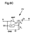
別の検出モードに従って接触面上に移植された複数の導体から3つの導体又は導体の3つの群を選択した後に、中央又は軸線方向(対称面)である第1の導体Xに検出Sの役割を割り当てる。次に、横導線XIに正の電位ジャンプ(「正」分極P+という経路上の刺激ΔVP)を、反対側で対称形である別の横導線IXに反対の負の電位ジャンプ(負分極P−という刺激ΔVN)を印加する。2つの横導線IX及びXIは、供給電位P−及びP+に接続されており、従って、低インピーダンスであり、一方、検出Sの第1の導体Xは、検出経路S上の電位ジャンプの発現を検出するために、検出回路CD(比較器又は増幅器)の差動入力部(−)に接続されているが高インピーダンス状態のままである。最初に、電位ジャンプの検出というこの段階の前に、その後の検出という第2の段階中に電位ジャンプの可能性を検出するために基準電位が確立される較正又は基準の段階がある。 The role of the detection S on the first conductor X which is central or axial (symmetric plane) after selecting three conductors or three groups of conductors from a plurality of conductors implanted on the contact surface according to another detection mode Assign. Next, a positive potential jump (stimulus ΔVP on the path of “positive” polarization P +) to the horizontal conductor XI, and a negative potential jump (negative polarization P−) to another lateral conductor IX that is symmetrical on the opposite side. The stimulus ΔVN) is applied. The two horizontal conductors IX and XI are connected to the supply potentials P− and P + and are therefore low impedance, while the first conductor X of the detection S has the potential jump on the detection path S developed. For detection, it is connected to the differential input (-) of the detection circuit CD (comparator or amplifier) but remains in a high impedance state. Initially, prior to this phase of potential jump detection, there is a calibration or reference phase in which a reference potential is established to detect potential jumps during the second phase of subsequent detection.
第1のつまり基準段階α中に、検出経路Sの導体Xは、検出回路CD(低インピーダンスのS)の、入力部−に印加された基準電位(電圧源)で短絡状態であり、2つの横導線IX及びXIは、確立された電位又は電位(中性化、接地GND)に設定されている。電位同士は、逆であるであることが好ましく、すなわち、分極P+及びP−は、交換され、高い方の電位(VDD)は導体IXに、低い方の電位(GND又は−VCC)は他方の導体XIに印加される。第2つまり検出段階β中に、比較器回路CDの他方の差動入力部+に印加された検出経路Sは、基準電位(高インピーダンスの状態)から切り離される。切り離された検出経路Sの導体Xは、容量電荷を保存する。正の電位ジャンプΔVPは、導体XIに接続した分極経路P+に印加され、負の電位ジャンプΔVNは、導体IXに接続した他方の分極トラックP−に印加される。次に、検出経路S上で、指、物体又は物がトラックIX、X、又はXIのうちの1つに接近した場合、電位ジャンプが相転移α/β中に生成されることが見出されている。第1の段階α中に(電位ジャンプ前に)軸線方向導体Xに接続した検出経路S上で得られた電位のレベルは、従って、検出というこの代替モードにおいて基準として機能する。検出経路S上で見られる電位ジャンプの方向は、トラックXのいずれかの側で、すなわち、IX又はXIで接触の位置が特定されているかを示している。 During the first or reference phase α, the conductor X of the detection path S is short-circuited with a reference potential (voltage source) applied to the input − of the detection circuit CD (low impedance S) The horizontal conductors IX and XI are set to an established potential or potential (neutralization, ground GND). The potentials are preferably reversed, i.e. the polarizations P + and P- are exchanged, the higher potential (VDD) on the conductor IX and the lower potential (GND or -VCC) on the other. Applied to conductor XI. During the second or detection phase β, the detection path S applied to the other differential input + of the comparator circuit CD is disconnected from the reference potential (high impedance state). The separated conductor X of the detection path S stores a capacitive charge. The positive potential jump ΔVP is applied to the polarization path P + connected to the conductor XI, and the negative potential jump ΔVN is applied to the other polarization track P− connected to the conductor IX. Next, it is found that on the detection path S, a potential jump is generated during the phase transition α / β when a finger, object or object approaches one of the tracks IX, X, or XI. ing. The level of potential obtained on the detection path S connected to the axial conductor X during the first phase α (before the potential jump) therefore serves as a reference in this alternative mode of detection. The direction of the potential jump seen on the detection path S indicates on either side of the track X, that is, whether the position of the contact is specified by IX or XI.
このような電位ジャンプは、従って、物体の存在又は触知性接近が一方では導体IX及びX、他方では導体XとXI間の2つの静電又は容量結合の一方を摂動させることを示すことができる。有利な態様では、2つの段階αとβの間で、2対の導体IX〜X及びX〜XI間の結合の不均衡を定量化するために、適用可能である場合に切換可能なコンデンサの列を並列に接続することによって入力側で不均衡を補償することにより、及び/又は検出経路Sに接続した変動点と分極経路P+P−の間に可変キャパシタンス回路の、より一般的には、可変移送キャパシタンス回路の同等のキャパシタンスを変えることにより、電位ジャンプSの可能性を検出することを発明により提案する。可変移送キャパシタンス回路又は切換可能なコンデンサ列は、2つの経路P+とSの間、及び2つの経路SとP−の間で並列であり、従って、「入力」経路と平行に接続したキャパシタンスを含む。「出力部」では、検出経路Sは、2つの静電又は容量結合間の均衡が再確立された時を検出する分別検出回路(比較器又は増幅器)に適用される。このような再均衡化は、最初に発現した不均衡を中性化するために追加しなければならなかった可変移送キャパシタンス回路又はコンデンサの列のキャパシタンスのデジタル値に基づいて3つのビーム経路を形成している導体の2対の間の2つの結合の不均衡を定量化することを可能にするものである。 Such a potential jump can therefore indicate that the presence or tactile approach of the object perturbs one of the two electrostatic or capacitive couplings between conductors IX and X on the one hand and conductors X and XI on the other hand. . In an advantageous manner, a switchable capacitor, if applicable, is quantified to quantify the coupling imbalance between the two pairs of conductors IX to X and X to XI between the two stages α and β. Compensating the imbalance on the input side by connecting the columns in parallel and / or of the variable capacitance circuit, more generally variable, between the variation point connected to the detection path S and the polarization path P + P− The invention proposes to detect the potential jump potential S by changing the equivalent capacitance of the transfer capacitance circuit. The variable transfer capacitance circuit or switchable capacitor string is in parallel between the two paths P + and S and between the two paths S and P- and thus includes a capacitance connected in parallel with the "input" path. . In the “output”, the detection path S is applied to a fractionation detection circuit (comparator or amplifier) that detects when the balance between the two electrostatic or capacitive couplings is reestablished. Such rebalancing creates three beam paths based on the digital value of the capacitance of the variable transfer capacitance circuit or capacitor row that had to be added to neutralize the initially developed imbalance. It is possible to quantify the two coupling imbalances between two pairs of conducting conductors.
有利な態様では、異なる経路の間の静電又は容量不均衡の補償の手段は、1つのそれぞれの経路と、接地又は供給電位のような安定した基準電位に接続することができ、又は検出経路Sのような別の経路に接続した変動点を形成することができる1つの中性化点との間に並列に接続した少なくとも1組のコンデンサを含む切換可能なコンデンサバンクとして具現化される。切換可能なコンデンサの列においては、並列である各分岐部は、キャパシタンスの判断値を有するコンデンサと直列であるスイッチ(好ましくは電子スイッチ、トランジスタ型式の)を含む。キャパシタンスの値は、分岐部間に2つずつ(2又は1/2の比率)千鳥に配置され、この1組のスイッチは、デジタル指令の状態ビットにより制御されることが好ましい。従って、驚くべきことに、デジタル/容量変換回路、すなわち、入力部で2進デジタル制御値を有し、容量変換を実行し、すなわち、この2進デジタル値をこの可変キャパシタンス回路の出力部の2つの経路又は切換可能なコンデンサの列間に存在する容量値に変換する回路を取得する。更に、変形においては、このような回路は、第1の経路(P)又は第2の経路(P+)と第3の経路(S)の変動点との間にそれぞれ並列に接続した2つの切換可能なコンデンサの組を含むことができる。このような可変コンデンサ回路は、符号付き2進デジタル指令を受信することができ、2進符号に基づいて、第1の経路と中性化点又は変動点との間に追加された容量性インピーダンスを変えるたびに第1の組のコンデンサを切り換えるか、又は対称的に第2の経路と変動点(第3の経路S)の間に追加された他の容量性インピーダンスを変えるために第2の組のコンデンサを切り換えることができる。 Advantageously, the means for compensation of electrostatic or capacitive imbalance between different paths can be connected to one respective path and a stable reference potential such as ground or supply potential, or the detection path It is embodied as a switchable capacitor bank including at least one set of capacitors connected in parallel with one neutralization point that can form a variation point connected to another path such as S. In a switchable capacitor row, each branch in parallel includes a switch (preferably an electronic switch, transistor type) in series with a capacitor having a capacitance value. Capacitance values are preferably arranged in a staggered manner (2 or 1/2 ratio) between the branches, and this set of switches is preferably controlled by a digital command status bit. Thus, surprisingly, the digital / capacitance conversion circuit, i.e. having a binary digital control value at the input, performs a capacitance conversion, i.e. this binary digital value is converted to 2 at the output of the variable capacitance circuit. Obtain a circuit that converts to a capacitance value that exists between two paths or rows of switchable capacitors. Furthermore, in a variant, such a circuit comprises two switching circuits connected in parallel between the first path (P) or the second path (P +) and the variation point of the third path (S), respectively. A possible set of capacitors can be included. Such a variable capacitor circuit can receive a signed binary digital command and, based on the binary code, a capacitive impedance added between the first path and the neutralization or variation point. To switch the first set of capacitors each time, or symmetrically to change the other capacitive impedance added between the second path and the variation point (third path S). A set of capacitors can be switched.
デジタル/アナログ変換器の方法においては、デジタル指令による切換可能であるコンデンサの列によって形成されるこのような可変キャパシタンス回路は、デジタル/容量変換器と考えることができ、かつそれ自体、本発明を形成することができる。
更に、検出の第1のモードにおいては、入力経路R及びSの一方と又は入力経路R及びSの両方と平行である1組又は2組の切換可能なコンデンサを含む二重回路が稼動されるように見える。しかし、これらの2つの経路R及びSは、2つの入力経路間の静電均衡又は不均衡に応じて、コンデンサが対応する経路上に有する累積キャパシタンスを変えるために切換可能なコンデンサの列の入力部に新しいデジタル指令が印加されるかを指標Qの状態に従って判断される制御及び指令ユニットにループにより伝達される状態指標(ビットQ)を出力部で供給する比較器又は増幅器の2つの差動入力部(+及び−)上に印加される。このフィードバックループは、2つの経路間の静電均衡がもたらされるか又は静電均衡がほぼ具現化される点まで(定量化閾値まで)2進デジタル指令を増加又は低減することによって入力経路R又はSに印加されたキャパシタンスを修正するように作用する。この回路は、従って、一方又は2つの経路上に並列に取り付けられた切換可能なコンデンサの列と、差動比較回路と、他方の経路上のキャパシタンス値と比較した時に一方の経路のキャパシタンスの値を実質的に均等化(再均衡化)するために2つの経路間の回路の比較結果に応じて列コンデンサの切り換えに向けてデジタル指令を印加する制御ユニットとを含む。このような回路は、従って、入力経路により見られた上述のキャパシタンス値に対応するデジタル値の表示(二進法であることが好ましい)への一方の経路上に存在するキャパシタンス値の変換(一方の経路と安定した基準電位間)を提供する。このような回路は、アナログ/デジタル変換回路との類似を拡張する容量/デジタル変換器として先に見たデジタル/容量回路に対して二重的に考えることができる。
In the digital / analog converter method, such a variable capacitance circuit formed by a string of capacitors switchable by a digital command can be considered as a digital / capacitance converter and as such the present invention Can be formed.
Further, in the first mode of detection, a dual circuit is activated that includes one or two sets of switchable capacitors that are parallel to one of the input paths R and S or both of the input paths R and S. looks like. However, these two paths R and S depend on the electrostatic balance or imbalance between the two input paths, depending on the electrostatic capacitance balance or imbalance, the input of the switchable capacitor string to change the cumulative capacitance that the capacitor has on the corresponding path. Two differentials of a comparator or an amplifier that supply at the output part a control that determines whether a new digital command is applied to the part according to the state of the index Q and a state index (bit Q) transmitted by the loop to the command unit Applied on the input (+ and-). This feedback loop can be used to increase or decrease the binary digital command by increasing or decreasing the binary digital command to the point where electrostatic balance between the two paths is provided or until electrostatic balance is substantially implemented (up to the quantification threshold). Acts to modify the capacitance applied to S. This circuit therefore has a capacitance value in one path when compared to a row of switchable capacitors mounted in parallel on one or two paths, a differential comparison circuit, and a capacitance value on the other path. And a control unit for applying a digital command for switching the column capacitor in accordance with the comparison result of the circuit between the two paths. Such a circuit thus converts the capacitance value present on one path (preferably one path) into a digital value representation (preferably binary) corresponding to the above mentioned capacitance value seen by the input path. And a stable reference potential). Such a circuit can be considered twice as compared to the digital / capacitor circuit seen earlier as a capacitor / digital converter extending the analogy with the analog / digital converter circuit.
慣例により、本発明においては、電圧及び電位の基準は、接地と呼ぶこともある接地GNDに対して取ることとし、従って、接地の電位は、ゼロであることになる。
更に、スイッチとして図面に概略的に示すスイッチによる接続は、一般的に、あらゆる形式の技術のもの、すなわち、バイポーラ、電界効果(FET)、トンネル効果、絶縁酸化物(MOSFET)の金属ゲート、TFTなどとすることができるトランジスタのような電子スイッチによって具現化される。
By convention, in the present invention, voltage and potential references will be taken with respect to ground GND, sometimes referred to as ground, and therefore the ground potential will be zero.
Furthermore, the switch connections shown schematically in the drawing as switches are generally of any type of technology: bipolar, field effect (FET), tunnel effect, insulating oxide (MOSFET) metal gate, TFT Embodied by an electronic switch such as a transistor.
図1の全体図は、本発明により検出の原理を実行する電子回路の第1の機能図を示している。
本発明により、規則的なパターンに従って配置された一連の導体を含む表面は、導体への接触(そこからの近接性)を検出するための装置又は回路に関連付けられる。図1の略示する例においては、導体移植がある表面は、互いに等しく離間及び隔離された一連の平行な線形導電トラックから成る。導電トラックを含むこのような表面は、平面上に、すなわち、単一のレベルに移植された規則的なパターンであり、トラックは、並行式である。併進(スライダ)により保存されるこのような導電トラックパターンは、1次元と考えることができるが、2次元で固有の平面を占有する。
The general view of FIG. 1 shows a first functional diagram of an electronic circuit implementing the principle of detection according to the invention.
According to the present invention, a surface comprising a series of conductors arranged according to a regular pattern is associated with a device or circuit for detecting contact (proximity therefrom) to the conductors. In the illustrated example of FIG. 1, the surface with the conductor implant consists of a series of parallel linear conductive tracks equally spaced and isolated from each other. Such a surface containing conductive tracks is a regular pattern implanted on a plane, i.e. a single level, and the tracks are parallel. Such a conductive track pattern stored by translation (slider) can be considered one-dimensional, but occupies a unique plane in two dimensions.
本発明による接触検出装置の具現化のこの第1の形においては、導電トラックのこの表面に関連の回路又は装置は、以下を含む。
−3つの経路を形成する少なくとも3つの導電線P、R、Sのビーム:
・分極、励起、又は刺激の第1の経路P、
・基準の第2の経路R、及び
・検出の第3の経路S、
−以下の経路のいずれかに各導電トラック...、III、IV、V、VI、VII、...を個々にかつそれぞれ接続することを可能にする複数のスイッチング手段により又は複数のマルチプレクサ回路によって形成されたアドレス指定回路ICX:
・分極(刺激)の経路P、
・基準の経路R、
・検出の経路S、
・又は、恐らく、確立された電位、例えば、供給電位(VDD)、又は導体II、III、...、VII、...がアドレス指定SLCにより選択されなかった時には接地電位(GND)、
・又は、非切換状態においては、これらのスイッチングは、(高インピーダンス状態HI)と考えられるトラック...、III、...、VII、...を接続することができない、
・トラックは、あらゆる形式の技術、すなわち、バイポーラ、電界効果などとすることができる直接的な非抵抗接続により、特に、トランジスタのような抵抗が僅かな電子スイッチにより対応する経路と接続されることが好ましい。
−経路Pの分極(刺激)の第1の回路PUS、PDS、
−基準及び検出の2つの経路R及びSの放電の機能に役立つ別の分極回路RGS/SGS/EQS、
−重み付きキャパシタンスを追加して両方の経路R及びSの一方を均衡を取る(再均衡化する)ことを可能にする切換可能なコンデンサの列CPB又は可変移送キャパシタンスの回路、
−例えば、経路R及びSが印加され、かつ試験すべき基準及び検出のこれらの経路R、S間の容量又は静電均衡を可能にする増幅器又は比較器CMPを含む経路R及びSの均衡の比較の差動回路CC、及び
−例えば、マイクロプロセッサ回路、又は図1の例により、アドレス指定回路ICX分極回路PUS/PDS及びSGS/EQS/RGS、経路S及びR上に1つ又はいくつかの可変キャパシタンスを有する切換可能なコンデンサCPBの列、及び比較回路CCを制御するマイクロコントローラにより、構成された中央ユニットUC。
In this first form of implementation of the touch detection device according to the invention, the circuit or device associated with this surface of the conductive track comprises:
A beam of at least three conductive lines P, R, S forming three paths:
A first path P of polarization, excitation or stimulation,
The second path R of the reference, and the third path S of detection,
-Each conductive track in one of the following paths. . . , III, IV, V, VI, VII,. . . Addressing circuit ICX formed by a plurality of switching means or by a plurality of multiplexer circuits, which can be connected individually and respectively:
・ Polarization (stimulation) path P,
・ Standard route R,
-Detection path S,
Or perhaps an established potential, eg supply potential (VDD), or conductors II, III,. . . , VII,. . . Is not selected by the addressing SLC, the ground potential (GND),
• Or, in the non-switching state, these switchings are track. . . , III,. . . , VII,. . . Can't connect,
The track is connected to the corresponding path by a few electronic switches, in particular by a direct non-resistance connection, which can be any type of technology, ie bipolar, field effect, etc. Is preferred.
The first circuit PUS, PDS of the polarization (stimulation) of the path P,
Another polarization circuit RGS / SGS / EQS which serves the function of the discharge of the two paths R and S of reference and detection,
A switchable capacitor string CPB or a variable transfer capacitance circuit that allows adding a weighted capacitance to balance (rebalance) one of both paths R and S;
The path R and S are balanced, for example, including an amplifier or comparator CMP that allows the paths R and S to be applied and the capacitance or electrostatic balance between these paths R, S of the reference and detection to be tested; A differential circuit CC for comparison, and, for example, a microprocessor circuit or one or several on the addressing circuit ICX polarization circuits PUS / PDS and SGS / EQS / RGS, paths S and R, according to the example of FIG. A central unit UC constituted by a row of switchable capacitors CPB having a variable capacitance and a microcontroller controlling the comparison circuit CC.
比較回路CCの出力Q、すなわち、比較又は均衡試験の結果を示す状態ビットを受信する中央ユニットつまり制御ユニットUCは、以下の適切な指令を通じて、装置の異なる回路(すなわち、アドレス指定回路及び分極回路、可変キャパシタンスCPBを有する切換可能なコンデンサの列、及び容量及び均衡試験を行う差動回路CC)を制御する:
−スイッチのアドレス指定及び選択のコードSLC、
−分極スイッチ段階指令(表さず)、
−再均衡化するか又は経路R及びS間の不均衡を補償するように意図したデジタル2進コードBLC、
−比較回路CCの較正及びサンプリングのための指令(AZ:ゼロリセット、SPL:サンプリング)。
The central unit or control unit UC, which receives the output Q of the comparison circuit CC, ie the status bit indicating the result of the comparison or balance test, passes the different circuits of the device (ie the addressing circuit and the polarization circuit) through the following appropriate instructions: A switchable capacitor string having a variable capacitance CPB, and a differential circuit CC) that performs capacitance and balance tests:
The switch addressing and selection code SLC;
-Polarization switch stage command (not shown),
A digital binary code BLC intended to rebalance or compensate for the imbalance between paths R and S;
-Commands for calibration and sampling of the comparison circuit CC (AZ: zero reset, SPL: sampling).
この第1の代替においては、導電線P又は分極経路は、接触(すなわち、指又は物又凝縮物体の存在)に感応する表面PADの導電トラック又はいくつかの導電トラックの群の1つを分極するという中心的な役割を有する。
ビームの他の2つの導電線R及びSは、それぞれ、基準経路R及び検出経路Sを形成する。
本発明の第1の代替に沿って、この導電線の3つ組を形成する経路P、R、及びSの各々は、それぞれ、タブレットの対応する導電トラック...、V、VI、VII、...と接続することを計画している。
In this first alternative, the conductive line P or polarization path polarizes the conductive track or one of a group of several conductive tracks on the surface PAD that is sensitive to contact (ie the presence of a finger or object or condensed object). Has a central role to do.
The other two conductive lines R and S of the beam form a reference path R and a detection path S, respectively.
In accordance with the first alternative of the present invention, each of the paths P, R, and S forming this triple of conductive lines is respectively a corresponding conductive track. . . , V, VI, VII,. . . Are planning to connect with.
簡素かつ有利であり、かつ図1における例として示す第1の構成においては、ビームの第1の導電線P、すなわち、分極経路Pは、支持部PADの選択トラック、ここでは、中央の導電トラックVに接続されている。このトラックVは、次に、対称軸に関する基準として機能する。ビームの第2の導電線すら基準経路Rは、隣接する横トラックIVと接続されている。これは、図1で見られる簡単な構成などにおいて隣接トラックIV(接してはおらず、かつ必ずしも直近というわけではない)、又はIII又はIIのような更に離れているその後のトラックとすることができる。検出ビームの第3の導電線Sつまり経路Sは、軸線方向トラックVの他方の隣接トラック又はその後のトラックVII、...とすることができる第3のトラックと接続されている。 In the first configuration, which is simple and advantageous and shown as an example in FIG. 1, the first conductive line P of the beam, ie the polarization path P, is the selected track of the support PAD, here the central conductive track. Connected to V. This track V then serves as a reference for the axis of symmetry. Even the second conductive line of the beam is connected to the adjacent transverse track IV. This can be an adjacent track IV (not touching and not necessarily closest), or a later track that is further away such as III or II, such as in the simple configuration seen in FIG. . The third conductive line S or path S of the detection beam is connected to the other adjacent track of the axial track V or the subsequent tracks VII,. . . And is connected to a third track.
機能において、マイクロコントローラは、アドレス指定バスで適切な選択のアドレス指定指令SLCをアドレス指定及び制御回路の1組のスイッチに送り、アドレス指定及び制御回路は、接続され、すなわち、以下のような接続を引き起こす(図1の構成例に従って):
−ビームの分極経路Pは、導電トラックVに接続される。
−第2の導電トラックIVは、基準経路Rに接続される。
−第3の導電トラックVIは、検出経路Sに接続される。
最後の2つ、すなわち、検出経路S及び基準経路Rは、比較回路CMPの2つの差動入力部+及び−に接続され、各々の線S又はRと接地GND(固定基準の又はあらゆる他の確立された電位)との間に並列に接続した2組のコンデンサCS0、CS1、CS2、...及びCR0、CR1、CR2、...に接続される。
In function, the microcontroller sends an appropriately selected addressing command SLC on the addressing bus to a set of switches in the addressing and control circuit, and the addressing and control circuit is connected, i.e. connected as follows: (According to the configuration example of FIG. 1):
The polarization path P of the beam is connected to the conductive track V;
The second conductive track IV is connected to the reference path R;
The third conductive track VI is connected to the detection path S;
The last two, namely the detection path S and the reference path R, are connected to two differential inputs + and − of the comparison circuit CMP, each line S or R and ground GND (fixed reference or any other Set of capacitors CS0, CS1, CS2,. . . And CR0, CR1, CR2,. . . Connected to.
分極経路Pは、電位を優位な値にする例えば正の供給電位VDDまで上げるプルアップスイッチPUSと、電位を電源の接地GNDのような低い値(負又はゼロ)にするプルダウンスイッチPDSとを含む第1の分極回路に接続されている。
基準R及び検出Sの他の2つの経路は、例えば、図1の例における具現化に従ってSGS、EQS、RGSのような2つ又は3つのスイッチを含む分極又は脱分極(放電)の別の回路に接続されている。接地電位に設定する第1のスイッチRGSは、基準経路Rを接地のような安定した電位のレベルに接続される。接地電位に設定する別のスイッチSGSは、検出経路Sを安定した電位のレベル、ここでは、同じ接地電位に接続される。更に、基準R及び検出Sの2つの経路は、代替的に又は累積的に電位水平調節又は短絡のスイッチEQSにより直接的に相互接続することができ、従って、短絡により、浮動電位とし、かつ接地又はスイッチSGS及び/又はRGSの閉成により課さされると思われる他の安定した電位と異なるとすることができる同じ電位にすることができる。
The polarization path P includes a pull-up switch PUS that raises the potential to a dominant value, for example, to a positive supply potential VDD, and a pull-down switch PDS that raises the potential to a low value (negative or zero) such as the ground GND of the power supply. Connected to the first polarization circuit.
The other two paths of the reference R and the detection S are for example another circuit of polarization or depolarization (discharge) comprising two or three switches such as SGS, EQS, RGS according to the implementation in the example of FIG. It is connected to the. The first switch RGS that is set to the ground potential is connected to the reference path R at a stable potential level such as ground. Another switch SGS that sets the ground potential is connected to the detection path S at a stable potential level, here the same ground potential. Furthermore, the two paths of reference R and detection S can alternatively or cumulatively be interconnected directly by a potential leveling or short circuit switch EQS, so that a short circuit causes a floating potential and a ground connection. Or it can be the same potential that can be different from other stable potentials that would be imposed by the closure of the switches SGS and / or RGS.
機能において、本発明は、トラックを精査することにより、すなわち、タッチパッド又はタッチスクリーンのような支持タッチ面の導電トラックの異なる3つ組を各対処時に選択することにより、一連の読取作動(試験又は厳密な調査)全体を実行する。
各読取作動においては、少なくとも3つの導電トラック、すなわち、分極Pに1つ、基準Rにもう1つ、検出Sに更にもう1つが選択される。
各読取作動中に、図4に示すように、段階1、段階2、及び/又は段階3といういくつかの(2つ又は3つの)段階が区別される。
In function, the present invention provides a series of read operations (tests) by reviewing the tracks, i.e., selecting different triads of conductive tracks on a supporting touch surface, such as a touch pad or touch screen, during each treatment. (Or rigorous investigation).
In each reading operation, at least three conductive tracks are selected, ie one for polarization P, one for reference R and one more for detection S.
During each reading operation, several (two or three) stages are distinguished,
最初に及び全体的な読取(試験又は精査)作動中に、マイクロコントローラのアドレス指定バスSLCは、図1における構成に従って分極経路Pが導電トラックVと接続され、隣接トラックIVが基準経路Rと接続され、残りの隣接トラックVIが検出経路Sと接続されるように電子スイッチを位置決めする選択指令SLCを送る。
第1の段階(φ1)では、第1の経路Pは、第1の分極回路PUS−PDSにより、安定した基準電位VP1、好ましくは接地電位GNDになる。プルダウン電子スイッチPDSは、例えば、線Pの電位Uを接地GNDの電位0にするために閉成される。
同じ段階φ1中に、電位ΔVSRの既知の差が、第2の経路Rと第3の経路Sの間に、従って、ここでは導電トラックIVとVI(図1の例)の間に印加される(課せられる)。この電位又は電圧の差でΔVSR=Us−URはゼロであり、すなわち、2つの基準及び検出の経路R及びSの導電線は同じ電位になることが好ましい。図1の具現化の例に従って、以下によりこのような課せられた分極を取得することができる:
−ビームの導電線R及びSを短絡させ、従って、それぞれの電位が均等化されるように電子スイッチEQSを閉成することにより、又は
−これらの2つの基準及び検出R及びSの経路が同じ絶対電位0であるように、各制御線S又はRの電位を接地GNDの電位0にするために2つのプルダウンスイッチSGS及びRGSを閉成することにより、
−代替的に、プルダウン又はプルアップスイッチは、簡単な方法で非ゼロ電位差Δ=VS1−VS1≠0を確立するために1つの又は各々のS又はRを個々に非ゼロ電位VS1又はVS2に接続することができ、
−又は、これらの3つのスイッチSGS、EQS、RGSを閉成することによる。それによって明らかに2つの検出及び基準の経路S及びRの電位は、接地GNDの同じヌル電位0になる。
During the initial and overall reading (testing or probing) operation, the microcontroller addressing bus SLC connects the polarization path P with the conductive track V and the adjacent track IV with the reference path R according to the configuration in FIG. Then, a selection command SLC for positioning the electronic switch is sent so that the remaining adjacent track VI is connected to the detection path S.
In the first stage (φ1), the first path P becomes the stable reference potential VP1, preferably the ground potential GND, by the first polarization circuit PUS-PDS. The pull-down electronic switch PDS is closed in order to set the potential U of the line P to the
During the same phase φ1, a known difference in potential ΔVSR is applied between the second path R and the third path S, and thus here between the conductive tracks IV and VI (example of FIG. 1). (I will be imposed). At this potential or voltage difference, ΔVSR = U s −U R is zero, ie, the conductive lines of the two reference and detection paths R and S are preferably at the same potential. According to the embodiment of FIG. 1, such imposed polarization can be obtained by:
By short-circuiting the conductive lines R and S of the beam and thus closing the electronic switch EQS so that the respective potentials are equalized, or the paths of these two reference and detection R and S are the same By closing the two pull-down switches SGS and RGS in order to bring the potential of each control line S or R to the
-Alternatively, a pull-down or pull-up switch connects one or each S or R individually to a non-zero potential VS1 or VS2 to establish a non-zero potential difference Δ = VS1-VS1 ≠ 0 in a simple manner Can
Or by closing these three switches SGS, EQS, RGS. This clearly causes the potentials of the two detection and reference paths S and R to be the same
この第1の段階φ1中に、分極経路P及び従って導電トラックVは、例えば、0のような基準電位になり、基準経路及び検出経路R及びS及び従って導電トラックIV及びVIは、既知の電位(又は電圧=電位差)、好ましくはヌル0になることになる。
この段階中に、既知の電位又は電圧、好ましくはゼロ(0)は、比較器CMPの入力部±で課せられることになる。マイクロコントローラUCは、出力がゼロであるように均衡又は更に正確に言えば較正を強制するために、ゼロリセット指令AZを比較器CMPに印加することが計画されている(これは、特に、非ゼロ電位差ΔVSR≠0が比較器CMPの入力部+及び−で経路S及びR間に印加される代替において必要である)。任意的に、比較回路の測定又は定量化誤差は、この場合に測定又は確立することができる。任意的に、導電トラックII、III、及びVII、並びにトラックV及び分極経路Pなど非アクティブ導体は、接地に接続するか又は浮動のままにし、すなわち、非接続状態、すなわち、「高インピーダンス」のレベルのままにすることができる。
作動のこの第1の段階(φ1)の終わりに、電位R、S、及び/又はPを引き下げ、つまり無効にしたプルダウンスイッチPDS、SGS、RGS、及び/又はEQSは、電位R及びSが浮動か又は「高インピーダンス」状態であるように弛緩状態(開成のスイッチ)である。
During this first phase φ1, the polarization path P and thus the conductive track V is at a reference potential, for example 0, and the reference path and detection paths R and S and thus the conductive tracks IV and VI are at a known potential. (Or voltage = potential difference), preferably
During this phase, a known potential or voltage, preferably zero (0), will be imposed at the input ± of the comparator CMP. The microcontroller UC is planned to apply a zero reset command AZ to the comparator CMP in order to balance or more precisely to force calibration so that the output is zero (this is not A zero potential difference ΔVSR ≠ 0 is necessary in an alternative where the inputs + and − of the comparator CMP are applied between the paths S and R). Optionally, the measurement or quantification error of the comparison circuit can be measured or established in this case. Optionally, non-active conductors such as conductive tracks II, III, and VII, and track V and polarization path P are connected to ground or left floating, ie, disconnected, ie, “high impedance”. You can leave the level.
At the end of this first phase of operation (φ1), pull-down switches PDS, SGS, RGS, and / or EQS that pull down, ie disable, the potentials R, S, and / or P cause the potentials R and S to float. Or in a relaxed state (open switch) as in a “high impedance” state.
次に、第2の段階(φ2)中に、電位ΔVPの変形が、刺激経路とも呼ばれる分極経路P上に課せられる。これは、ビームの分極経路P上のあらゆる電位UPを印加することにより、特に、供給VDDのような非ゼロの確立された基準電位のレベルで分極Pの線を短絡させることによって取得することができる。このようにして、図1の具現化の例に従って分極線Pを正の供給線VDDと接続するプルアップ又は電位増大スイッチPUSを閉成することによって分極経路Pの電源の電位、及び従って図1の例におけるトラックVの電位を上げることができる。 Next, during the second stage (φ2), a deformation of the potential ΔVP is imposed on the polarization path P, also called the stimulation path. This can be achieved by applying any potential U P on the beam of the polarization path P, in particular, it is obtained by shorting the lines of polarization P at the level of the non-zero established reference potential such as supply VDD Can do. In this way, the potential of the power supply of the polarization path P, and thus FIG. 1 by closing the pull-up or potential increase switch PUS connecting the polarization line P to the positive supply line VDD according to the embodiment of FIG. In this example, the potential of the track V can be increased.
この結果、この第2の段階φ2中に、経路P及び軸線方向トラックVは、段階1の残留電位VP1と異なる新しい電位VP2になる。同等方式で、第1の分極回路は、基準φ1(較正)及び試験φ2(検出)の段階、及び一部の場合には、本発明の第1の代替に従って実施される基準経路と基準経路R及びS(比較及び/又は定量化)間の容量不均衡の定量化段階φ3の連続を示す図4における段階φ1、φ2、...、φ1、φ2のタイムチャートによって示唆されているように、分極Pの線上で第1の分極回路は電圧ジャンプ(遷移前線により分離された2つの電位レベルの電圧ジャンプ又は矩形信号(?)又は連続)を印加すると規定することができる。
As a result, during this second stage φ2, the path P and the axial track V become a new potential VP2 different from the residual potential VP1 of
この第2の段階(φ2)中に、より正確には、サンプリング段階(φ3)中に、入力部+及び−が基準経路R及び検出経路Sを受け取る比較回路CMPの助けを借りて検出経路Sと基準経路Rの間の電位差を通じて容量不均衡、すなわち、静電荷の不均衡を検出する。
より正確には、本発明の具現化の代替中に、基準経路Rと検出経路Sの間の静電不均衡を定量化することが計画されている。
より正確には、このような検出又は物理的測定段階は、2つの経路S及びR間の、すなわち、基準IV及び検出VIの導電トラック間の容量不均衡の可能性を定量化すること(図1の指示的例に従って)、又は他の場合には基準経路R及び検出経路Sが均衡状態(平衡状態)であること、すなわち、トラックIV及びVIが静電平衡状態にあることを確認することにある。
During this second phase (φ2), more precisely, during the sampling phase (φ3), the input paths + and − receive the reference path R and the detection path S with the help of the comparison circuit CMP and the detection path S And the reference path R are used to detect a capacitive imbalance, that is, an electrostatic charge imbalance.
More precisely, it is planned to quantify the electrostatic imbalance between the reference path R and the detection path S during an alternative implementation of the invention.
More precisely, such a detection or physical measurement step quantifies the possibility of capacitive imbalance between the two paths S and R, ie between the conductive tracks of the reference IV and the detection VI (FIG. Confirm that the reference path R and the detection path S are in equilibrium (equilibrium), i.e. that the tracks IV and VI are in electrostatic equilibrium. It is in.
物理的な説明の始めとして、電気的結合は、電位Pになった軸線方向トラックVと隣接トラック...、III、IV、及びVI、VII、...、特に、直近の横トラックIV及びVIとの間に確立されるように思われる。この段階φ2では、経路R及びSに接続されているトラックIV及びVIは、浮動又は「高インピーダンス」状態である。静電的性質、より正確には、推測的な容量的性質である2つの横結合は、基準軸線方向トラックV上の分極電圧ジャンプΔVPの影響を受けて隣接導電トラックIV、VI、及び従って経路R及びSの各々の電位の変換を誘発する。 As the beginning of the physical description, the electrical coupling consists of the axial track V at the potential P and the adjacent track. . . , III, IV, and VI, VII,. . . In particular, it seems to be established between the latest lateral tracks IV and VI. At this stage φ2, the tracks IV and VI connected to the paths R and S are in a floating or “high impedance” state. The two lateral couplings, which are electrostatic properties, more precisely speculative capacitive properties, are influenced by the polarization voltage jump ΔVP on the reference axial track V and are adjacent to the conductive tracks IV, VI and thus the path. Induces a conversion of the potential of each of R and S.
特定のトラック、例えば、図2Bに示すようなV−VIの環境が、指DGの接近のような空気又は真空以外の物体DGの存在、又は空気又は真空ε0又はμ0のものと明らかに異なるペン、定規又は探り針により、金属性か否かに関わらず、導電性か否かに関わらず、すなわち、誘電率ε1又は透磁率μ1の凝縮物体のような物の存在により摂動された場合、軸線方向トラックVと隣接トラックVIの間の電気的結合又は静電結合は、この存在により摂動及び修正される。
より正確には、触知性接触DGは、2つの隣接トラックV及びVIの間に存在する静電結合又は容量結合の値を修正すると考えられ、その値は、通常、これらの2つのトラック間の寄生容量又は漏れコンダクタンス(インピーダンスの逆)と考えられている。この現象は、些細なものである。
The environment of a particular track, e.g. V-VI as shown in Fig. 2B, is clearly the presence of an object DG other than air or vacuum, such as the proximity of a finger DG, or that of air or vacuum ε 0 or μ 0 Being perturbed by different pens, rulers or styluses, whether metallic or not, whether conductive or not, i.e. the presence of objects such as condensed matter with a dielectric constant ε 1 or permeability μ 1 The electrical or electrostatic coupling between the axial track V and the adjacent track VI is perturbed and modified by this presence.
More precisely, the tactile contact DG is considered to modify the value of the electrostatic or capacitive coupling that exists between two adjacent tracks V and VI, which is usually between these two tracks. It is considered as parasitic capacitance or leakage conductance (inverse of impedance). This phenomenon is trivial.
それを検出するために、本発明は、独創的かつ有利な態様では、再均衡化すべきである経路S又はRと接地GND又はVDDのようなあらゆる他の安定した電位との間に並列に接続した均衡錘キャパシタンスの追加で中性化することによって静電結合のこのような変形を補償することを提案する。これは、検出S及び基準Rの各々の経路上に、対応する経路S又はRと接地GNDのような確立された電位の間に並列に取り付けられた切換可能なコンデンサCS0、CS1、CS2、...又はCR0、CR1、CR2、...の列CPBを導入することによって本発明により通常とは異なって許容される。 In order to detect it, the present invention, in an inventive and advantageous manner, connects in parallel between the path S or R to be rebalanced and any other stable potential such as ground GND or VDD. It is proposed to compensate for this deformation of the capacitive coupling by neutralizing with the addition of the balanced weight capacitance. This is on each path of the detection S and the reference R, switchable capacitors CS0, CS1, CS2,... Mounted in parallel between the corresponding path S or R and an established potential such as ground GND. . . Or CR0, CR1, CR2,. . . This is allowed by the present invention by introducing a series of CPBs.
切換可能なコンデンサの各々は、ビームの検出S又は基準Rの経路に対応する導電線と、上述の経路S又はRと安定した電位、すなわち、接地GNDとの間に並列に取り付けられた1組のいくつかのコンデンサCS0、CS1、CS2などとで構成される。各分流器は、導電線Sと接地基準電位GNDの間の電子スイッチKS0と直列であるコンデンサCS0を含む。スイッチKS0がマイクロコントローラUCの適切な制御コードBLCにより開成された時、コンデンサCS0は、回路外にあり、そのキャパシタンスは、接地GNDに対する線Sの全体的キャパシタンスには含まれない。全てのスイッチKS0、KS1、KS2などがマイクロコントローラUCの均衡制御コードBLCにより開成された時、接地GNDに対する線Sの自己キャパシタンスCSiにはキャパシタンスは追加されない。スイッチKS0が粗制御ユニットUCからの適切な再均衡化制御コードBLCにより閉成された時、コンデンサCS0のキャパシタンスの値は、線Sと、経路Sが接続されている導電トラックとの自己キャパシタンスに追加される。スイッチKS0及びKS1が適切な再均衡化コードBLCにより閉成された時、2つのコンデンサCS0及びCS1は、線Sと接地電位GNDの間の回路に入れられ、これらのコンデンサCS0+CS1のキャパシタンスの値の累積は、経路Sの自己キャパシタンスCSiに追加される。3つのスイッチKS0、KS1、及びKS2が適切な再均衡化コードBLCにより閉成された時、3つのCS0、CS1、CS2は、線Sと接地GNDの間の回路に入れられ、キャパシタンスCS0+CS1+CS2の値の累積は、トラックSの自己キャパシタンスCSiに追加される。 Each of the switchable capacitors is a set mounted in parallel between a conductive line corresponding to the path of the beam detection S or reference R and the above-described path S or R and a stable potential, i.e., ground GND. And several capacitors CS0, CS1, CS2, etc. Each shunt includes a capacitor CS0 in series with an electronic switch KS0 between conductive line S and ground reference potential GND. When switch KS0 is opened by the appropriate control code BLC of microcontroller UC, capacitor CS0 is out of circuit and its capacitance is not included in the overall capacitance of line S to ground GND. When all the switches KS0, KS1, KS2, etc. are opened by the balance control code BLC of the microcontroller UC, no capacitance is added to the self-capacitance CSi of the line S with respect to the ground GND. When the switch KS0 is closed by a suitable rebalancing control code BLC from the coarse control unit UC, the capacitance value of the capacitor CS0 is the self-capacitance of the line S and the conductive track to which the path S is connected. Added. When the switches KS0 and KS1 are closed by the appropriate rebalancing code BLC, the two capacitors CS0 and CS1 are put into a circuit between the line S and the ground potential GND, and the value of the capacitance of these capacitors CS0 + CS1. The accumulation is added to the self-capacitance CSi of path S. When the three switches KS0, KS1, and KS2 are closed by the appropriate rebalancing code BLC, the three CS0, CS1, CS2 are put into a circuit between the line S and the ground GND and the value of the capacitance CS0 + CS1 + CS2 Is added to the self-capacitance CSi of the track S.
その結果として、接触面の導電トラックVI(経路S)の近くの物体の存在及び特に指の接近が容量性電荷を高めた時、マイクロコントローラUCは、コンデンサCS0、CS1、CS2、...の選択の切り換えを制御された方式で制御することができ、キャパシタンス累積値CS0又はCS0+CS1、又はCS0+CS1+CS2は、変動を補償して、調節された方式で均衡を再確立するために線Sの固有キャパシタンスCSiに追加される。 As a result, when the presence of an object near the conductive track VI (path S) on the contact surface and particularly the approach of the finger increases the capacitive charge, the microcontroller UC will have capacitors CS0, CS1, CS2,. . . The switching of the selection can be controlled in a controlled manner, and the accumulated capacitance value CS0 or CS0 + CS1, or CS0 + CS1 + CS2 compensates for variations and reestablishes the balance in an adjusted manner to the intrinsic capacitance of line S. Added to CSi.
この趣旨で、この種の容量性均衡錘を静電結合の変動に蓄積することができるように、基準に対する比較を行うことが必要である。これは、接触支持体(タッチパッド又はタッチスクリーン)の表面の別の導電トラックIVに接続されている基準経路Rの役割である。基準経路Rが接続されている導電トラックIVは、分極Pの導電トラックVとの静電又は容量結合のそれぞれの値が実質的に同じであるように、検出Sの導電トラックVIと対称形になるように選択される。接触面上に又は接触面の下方に移植された規則的なパターンの導電トラックII、III、IV、V、VI、VII、又はVIII、IX、X、XI、XIIが選択されることになる。更に、第1の段階φ1中に、比較回路CMPは、この差動回路CCを較正することを可能にするゼロリセット指令AZを受信する。 To this effect, it is necessary to make a comparison to a reference so that this type of capacitive counterweight can be accumulated in the variation of electrostatic coupling. This is the role of the reference path R connected to another conductive track IV on the surface of the contact support (touchpad or touch screen). The conductive track IV to which the reference path R is connected is symmetrical to the conductive track VI of the detection S so that the respective values of electrostatic or capacitive coupling with the conductive track V of the polarization P are substantially the same. Selected to be. A regular pattern of conductive tracks II, III, IV, V, VI, VII or VIII, IX, X, XI, XII implanted on or below the contact surface will be selected. Furthermore, during the first phase φ1, the comparison circuit CMP receives a zero reset command AZ that makes it possible to calibrate the differential circuit CC.
この処理は、重み付けブリッジで二重の重み付けする原理と多少似たものであり、重み付けの較正の第1の段階中に、分量が秤上に置かれ、揺動点の位置を正確に特定するために小さな較正済み錘の連続を追加することによって均衡錘で均衡が取られ、次に、重み付けの第2の段階中に、分量が抜かれると、揺動点の平衡に戻るように小さな較正済み錘の合計での置換によりその不在分を補償する。追加した小さな較正済み錘の合計は、秤が正確であるか否か(均衡状態又は欠陥状態)ということとは独立して分量の正確な重量に対応する。 This process is somewhat similar to the principle of double weighting with a weighting bridge, during the first stage of weight calibration, the quantity is placed on the scale to pinpoint the position of the rocking point. A small calibration so that it is balanced with the balance weight by adding a series of small calibrated weights, and then returns to the oscillating point balance when the quantity is removed during the second stage of weighting. The absence is compensated by the replacement of the total weight. The sum of the small calibrated weights added corresponds to the exact weight of the quantity, independent of whether the scale is accurate (equilibrium or defective).
本発明により、マイクロコントローラUCは、多少似通った処理を実行することが予想される。まず第1の段階φ1中に比較回路を較正することにより、最初に、導電トラックIV、V、VIの近くの物体の存在の影響を相殺するために、基準及び検出の経路R、Sに同じ電位ΔVSR=0を課することになる。次に、第2の段階φ2中に、静電不均衡又は容量不均衡の可能性が、分極Pの影響を受けて検出及び基準の2つの経路S、R間に検出される。この場合、この不均衡は、摂動中の物体の存在を示すものであり、マイクロコントローラUCは、比較器CMPの出力Qの状態及び特にその符号の関数として、秤又は重み付けブリッジのプレートの重み付け又は再均衡化の方法で、均衡が再確立されるまで1組のコンデンサCS0、CS1、CS2、...又はそのうちの特定のコンデンサ、又は他方の1組のコンデンサCR0、CR1、CR2、...CRnのうちの特定のコンデンサを回路に入れるように(再均衡化)均衡コードBLCを増加又は低減するという処理をトリガする。 In accordance with the present invention, the microcontroller UC is expected to perform somewhat similar processing. First, by calibrating the comparison circuit during the first phase φ1, first the same as the reference and detection paths R, S in order to offset the influence of the presence of objects near the conductive tracks IV, V, VI The potential ΔVSR = 0 is imposed. Next, during the second phase φ2, the possibility of electrostatic imbalance or capacitive imbalance is detected between the two paths S, R of detection and reference under the influence of the polarization P. In this case, this imbalance indicates the presence of a perturbing object, and the microcontroller UC determines the weight of the plate of the balance or weighting bridge as a function of the state of the output Q of the comparator CMP and in particular its sign. In a rebalancing manner, a set of capacitors CS0, CS1, CS2,. . . Or one of them, or the other set of capacitors CR0, CR1, CR2,. . . Trigger the process of increasing or decreasing the balance code BLC to re-balance the specific capacitor of CRn into the circuit (rebalance).
連続的な近似により、すなわち、図3に示すように1つ及び同じ分極シーケンス中に、脱分極φ1及び再分極φ2の新しいシーケンスに進むことなく(放電ΔVSR=0でもなく新しい刺激Up=VP2でもなく、試験段階φ2中の比較器のいくつかの連続的サンプリングφ3、φ3’、φ3’’など)、回路に連続的にコンデンサCS0、次に、CS0+CS1のキャパシタンスを有する2つのコンデンサCS0及びCS1、次に、CS0+CS1+CS2のキャパシタンスを有する3つのコンデンサを入れることによって均衡を再確立することができる。 With a continuous approximation, ie, during one and the same polarization sequence as shown in FIG. 3, without proceeding to a new sequence of depolarization φ1 and repolarization φ2 (with no discharge ΔVSR = 0 or a new stimulus Up = VP2 Without, several successive samplings of the comparator during the test phase φ2, φ3, φ3 ′, φ3 ″, etc.), the capacitor CS0 continuously in the circuit, and then two capacitors CS0 and CS1, having a capacitance of CS0 + CS1, The balance can then be re-established by including three capacitors with a capacitance of CS0 + CS1 + CS2.
しかし、好ましくは、各々のサイクルで導電トラックの分極を再初期化することによっていくつかのサイクルでコンデンサCPBの列の制御のデジタルコードBLCを調節することが予想される。図4A〜図4Gは、回路に入れられるコンデンサのキャパシタンス値の調節のデジタル指令BLCの連続の関数としての切換可能なコンデンサの列の可変キャパシタンスの値の調節のサイクルA、B、C、Dの連続を概略的に示している。各サイクルA−B−C−D...の初期の段階φ1中に、ビームの3つの経路P、R、S及び対応するトラックIV、V、VIが放電される。再初期化パルスPDWは、導電トラックP、R、Sの放電及び分極の初期値への戻りを指令する。これは、3つの経路P、R、Sを接地GNDのゼロ電位のようなより低い基準電位に設定するためにスイッチPDS(プルダウンスイッチ)SGS、RGS、及び/又はEQSを閉成することによって為される。次に、各サイクルA−B−C−D...の第2の段階φ2中に、分極又は刺激のパルスPUPが印加されると、分極経路Pの電位Upを上部供給電位VDDのような確立された基準電位VP2まで引き上げるようにもう一度スイッチPUSの閉成を指令する。切換可能なコンデンサな列のキャパシタンス値を調節するための放電φ1及び再分極φ2のサイクルA−B−C−Dの連続は好ましいものであり、その理由は、有利な態様では、電荷注入現象を回避することを可能にするからであり、その理由は、切換可能なコンデンサの列のスイッチの開成及び閉成は、特に、中性化の電荷均衡がない電荷移動を誘発し、急速に平衡及び容量/デジタル変換への戻りを摂動するからである。放電のそれぞれの段階φ1(脱分極PDWの段階φ1のシーケンス)の最初に切換可能なコンデンサCPBの列の切り換えの指令BLCのあらゆる修正をもたらした後に、検出の段階φ2を行って分極UP(刺激P)の電位ジャンプΔVPに進み、次に、電位UR及びUSの比較CMPに進むことが一般的に好ましい。 However, it is preferably expected to adjust the digital code BLC for control of the column of capacitors CPB in several cycles by reinitializing the polarization of the conductive track in each cycle. 4A-4G show the cycle A, B, C, D of adjusting the variable capacitance value of a switchable capacitor array as a continuous function of the digital command BLC of adjusting the capacitance value of the capacitor placed in the circuit. The continuation is schematically shown. Each cycle A-B-C-D. . . During the initial phase φ1, the three paths P, R, S of the beam and the corresponding tracks IV, V, VI are discharged. The reinitialization pulse PDW commands the discharge of the conductive tracks P, R, S and the return to the initial value of the polarization. This is done by closing the switches PDS (pull-down switches) SGS, RGS, and / or EQS to set the three paths P, R, S to a lower reference potential, such as the zero potential of ground GND. Is done. Next, each cycle ABCDD. . . When the polarization or stimulation pulse PUP is applied during the second phase φ2, the switch PUS is once again activated to raise the potential U p of the polarization path P to an established reference potential VP2 such as the upper supply potential VDD. Command closure. The sequence of discharges φ1 and repolarization φ2 cycle A-B-C-D for adjusting the capacitance value of the switchable capacitor array is preferred because, in an advantageous manner, the charge injection phenomenon is reduced. This is because the opening and closing of the switch of the switchable capacitor array, in particular, induces a charge transfer without neutralizing charge balance, rapidly balancing and This is because the return to the capacitance / digital conversion is perturbed. After brought initially any modification of the command BLC switching of switchable capacitors CPB of columns in each stage of the discharge .phi.1 (sequence of steps .phi.1 depolarization PDW), performing the steps φ2 detection polarization U P ( It is generally preferred to proceed to the potential jump ΔVP of the stimulus P) and then proceed to the comparison CMP of the potentials U R and U S.
特に有利な態様では、2つのコンデンサの組CS0、CS1、CS2、...、CSn及びCR0、CR1、CR2、...、CRnを有する切換可能なコンデンサの列は、増加中又は減少中の値において、好ましくは、比率qの幾何学的連続:CS0=q・CSl=q・q・CS2で、好ましくは、CS0=2xCSl=2x2xCS2のような2の比率の連続で増加(減少)する際に千鳥配置であるキャパシタンス値を有することが本発明により計画されている。従って、1kg、500g、250gのような重量のサンプルのように、選択及び基準の2つの経路間の静電不均衡を補償してこの容量性列の回路によって実施される容量性再均衡化を調節するのに適切な(最小のキャパシタンスCS0又はCSnの誤差内で)キャパシタンスCS0、CS1、CS2、...、CSnの組合せを見つけることができる。 In a particularly advantageous manner, the two capacitor sets CS0, CS1, CS2,. . . , CSn and CR0, CR1, CR2,. . . , CRn, the row of switchable capacitors, preferably at increasing or decreasing values, preferably geometrically continuous with the ratio q: CS0 = q · CS1 = q · q · CS2, preferably CS0 = It is planned by the present invention to have a capacitance value that is staggered when continuously increasing (decreasing) in a ratio of 2, such as 2 × CS1 = 2 × 2 × CS2. Therefore, the capacitive rebalancing performed by the circuit in this capacitive row, compensating for the electrostatic imbalance between the two paths of choice and reference, such as samples weighing 1 kg, 500 g, 250 g, etc. Capacitances CS0, CS1, CS2,... Suitable for adjustment (within a minimum capacitance CS0 or CSn error). . . , CSn combinations can be found.
従って、図1の具現化の別の例に従って、入力線Sに平行に接続され、かつ別の入力線Rに平行に接続した切換可能なコンデンサの第2の組CRBを追加することができるコンデンサの第1の組CSBで構成された切換可能なコンデンサの列CPBを考え、かつ符号A±(例えば、8ビット、すなわち、1バイトを形成するために)A0、A1、A2、A3、...、A6、...、An及びA±のビットを追加することができる2、3、4、...、7、...、又はn+1ビットで符号化されたデジタル再均衡化コンデンサBLCを供給することができる。 Accordingly, in accordance with another example of the implementation of FIG. 1, a capacitor can be added that adds a second set of switchable capacitors CRB connected in parallel to the input line S and connected in parallel to another input line R. Consider a switchable capacitor string CPB composed of a first set of CSBs of A and A0 (for example, to form 8 bits, ie, 1 byte) A0, A1, A2, A3,. . . , A6,. . . , An and A ± bits can be added 2, 3, 4,. . . , 7,. . . Or a digital rebalancing capacitor BLC encoded with n + 1 bits can be provided.
第1のビットA0、A1、A2、...は、対応するコンデンサCS0、CS1、CS2、...、CSnの選択的切り換え及び回路挿入をトリガする。有利な態様では、コンデンサCS0、CS1、CS2、...、CSnのキャパシタンスは、容量性重み付けが対応するビットの重み付けつまり2進法の重量に対応するように2で千鳥配置されている。
従って、例えば、指令BLC=Aがゼロの値を有する時、2進符号A1−A2−A3−A4−...−An=00000000は、全てのスイッチの開成をトリガすると共に、線上に存在する全体的なキャパシタンスが値CSb=0を取るように全てのコンデンサを回路から離す。
The first bits A0, A1, A2,. . . Are the corresponding capacitors CS0, CS1, CS2,. . . , Trigger selective switching of CSn and circuit insertion. In an advantageous manner, the capacitors CS0, CS1, CS2,. . . The capacitance of CSn is staggered by 2 so that the capacitive weighting corresponds to the corresponding bit weighting, ie the binary weight.
Thus, for example, when the command BLC = A has a value of zero, the binary code A1-A2-A3-A4-. . . -An = 00000000 triggers the opening of all switches and keeps all capacitors away from the circuit so that the overall capacitance present on the line takes the value CSb = 0.
1の値又は2進符号A1−A2−A3−...−An=10000000に対して、コンデンサの列への指令BLC=Aは、1つのみのスイッチKS0を閉成し、回路は、線S上にキャパシタンスCSb=CS0を有する。
A0−A1−A2−A3−...−An…=01000000の2進符号に対応する2の値Aに対して、コンデンサの列への指令BLC=Aは、単一のスイッチKSlを閉成し、回路は、CS0の2倍(又は半分)であるキャパシタンスCSb=CS1を線S上に有する。
1 or binary code A1-A2-A3-. . . For -An = 10000000, the command BLC = A to the capacitor row closes only one switch KS0 and the circuit has a capacitance CSb = CS0 on line S.
A0-A1-A2-A3-. . . For a value of 2 corresponding to a binary code of −An... = 01000000, the command BLC = A to the capacitor string closes a single switch KSl and the circuit is doubled CS0 (or A capacitance CSb = CS1 on line S that is half).
A0−A1−A2−A3−...−An=11000000の2進符号に対応する3の値Aに対して、コンデンサの列への指令BLC=Aは、スイッチKS0及びKS1を閉成し、回路は、前出値の合計、すなわち、CS0(又はCS1)の3倍であるキャパシタンスCSb=CS0+CS1を線S上に有する。
以下同様である。
Nの2進分解に対応するNの値A又は2進符号A0−A1−A2−A3−...−Anに対して、コンデンサの列への指令BLC=Aは、回路が事実上回路に入れられたコンデンサのキャパシタンスの累積に対応するキャパシタンスCs=CS0±CSl±CS2±CS3±...±CSnを線S上に有するように、対応するビットA0−A1−A2−A3−...−Anの状態0又は1によってスイッチKS0、KS1、KS2、...、KSnを閉成するか又は閉成せず、上述の累積は、実際には、NxCS0(又はNxCSn)の値CSbを有する。
A0-A1-A2-A3-. . . -For a value of 3 corresponding to a binary code of An = 11000000, the command BLC = A to the capacitor string closes the switches KS0 and KS1, and the circuit calculates the sum of the preceding values, i.e. It has a capacitance CSb = CS0 + CS1 on line S that is three times CS0 (or CS1).
The same applies hereinafter.
N value A corresponding to binary decomposition of N or binary code A0-A1-A2-A3-. . . For An, the command BLC = A to the capacitor array is such that the capacitance Cs = CS0 ± CS1 ± CS2 ± CS3 ±. . . Corresponding bits A0-A1-A2-A3-... So as to have ± CSn on line S. . . -Switches KS0, KS1, KS2,. . . KSn is closed or not closed, and the above accumulation actually has a value CSb of NxCS0 (or NxCSn).
符号ビットA±が1の状態に対して状態を変えた時、例えば、事前の再発の関係に従ってそれぞれのキャパシタンスがA0−A1−A2−A3−...−Anの状態の関数として他の線R上で追加されるように、使用されるのは、他の組の切換可能なコンデンサCR0、CR1、CR2、CR3、...、CRnであることを選択肢として予想することができる。
驚くべきことに、スイッチがデジタル均衡コードBLCにより指令される切換可能なコンデンサの1つ又は2つの列CSB及びCRBから成る可変キャパシタンスの列CPBを含むこのような回路は、自動的かつ独創的なデジタル/アナログ変換器との類似により、デジタル/容量変換回路(CNC)を形成する。
When the sign bit A ± changes state with respect to 1, for example, the respective capacitances are A0-A1-A2-A3-. . . As used on the other line R as a function of the state of An, it is used that other sets of switchable capacitors CR0, CR1, CR2, CR3,. . . , CRn can be expected as an option.
Surprisingly, such a circuit comprising a variable capacitance column CPB consisting of one or two columns CSB and CRB of switchable capacitors commanded by a digital balance code BLC is automatic and ingenious. Similar to a digital / analog converter, a digital / capacitance conversion circuit (CNC) is formed.
本質的に補完的かつ独創的に、逆に、回路CPB、CMP、UCは、容量/デジタル変換(CCN)の回路を具現化する。
キャパシタンスCの値をキャパシタンスCの値を示すデジタル定量化Aに変換しがちであるこのような回路は、1つ又は2つの入力経路S/Rと、スイッチがデジタルコードBLC(指令、制御、選択、又は均衡)により指令される切換可能なコンデンサCSB/CRBの1組又は2組で構成された可変キャパシタンスCPBの列と、比較回路CCと、回路に入れられるコンデンサCS0、CS1、CS2、...、CSn又はCR0、CR1、CR2、...、CRnの数及びランクを指令する指令BLCに印加されたデジタルコードを増加又は低減することができるフィードバックをもたらす判断回路UCとを含む。
Essentially complementary and original, conversely, the circuits CPB, CMP, UC embody a capacitance / digital conversion (CCN) circuit.
Such a circuit, which tends to convert the value of the capacitance C into a digital quantification A indicating the value of the capacitance C, has one or two input paths S / R and a switch with a digital code BLC (command, control, selection). , Or balance), a series of variable capacitance CPB composed of one or two sets of switchable capacitors CSB / CRB, a comparison circuit CC, and capacitors CS0, CS1, CS2,. . . , CSn or CR0, CR1, CR2,. . . A decision circuit UC that provides feedback that can increase or decrease the digital code applied to the command BLC commanding the number and rank of CRn.
他の可変キャパシタンス手段も、検出及び基準S及びRの2つの経路を再均衡化して2つの静電結合間の不均衡の可能性の発現を補償するために本発明によって実施することができる。より一般的には、経路S及びRを再均衡化するために単なる可変キャパシタンスと同等の効果を有するための手段を含む他の可変移送キャパシタンス手段を実施することができる。後ほど注釈する図6A、図6B、図6C、及び図6Dは、接地GNDに対して基準経路R上で可変移送キャパシタンスが得られる回路の他の具現化を概略的に示している。 Other variable capacitance means can also be implemented by the present invention to rebalance the two paths of detection and reference S and R to compensate for the potential imbalance between the two capacitive couplings. More generally, other variable transfer capacitance means can be implemented, including means for having the same effect as a mere variable capacitance to rebalance paths S and R. FIGS. 6A, 6B, 6C and 6D, which will be annotated later, schematically illustrate another implementation of a circuit that provides a variable transfer capacitance on the reference path R with respect to ground GND.
キャパシタンスの受け入れられている定義は、2つの電位変動ΔV1及びΔV2を電荷の変動ΔQと結び付ける比例定数である。
ΔQ=ΔV1*C−ΔV2*C
可変キャパシタンスは、電荷と電位間の可変比例定数を意味する。この定数を修正する1つの方法は、コンデンサの相互接続配置を変えること、又はバリキャップとして使用されるダイオードのバイアス電位を変えることである。しかし、上述の公式が示すように、電位変動、例えば、ΔV1と電荷ΔQの変動間の比例を変える別の方法を図20B(単なるキャパシタンスを示す図20Aと比較されたい)に示している。可変利得(増幅又は減衰)係数kを有する増幅装置を加えると、電位変動ΔV1、及び従ってコンデンサの第1のリードで見られる実際の電位変動がkΔV1に修正される。利得係数kを変えると、電位変動ΔV1と電荷変動ΔQ間の比例定数を修正することができる。形式的には、コンデンサ要素のキャパシタンスは、利得kの修正により修正されるものではない。更に、図20Bに示す装置は、利得係数kを定めることができるように基準電位が必要であるために少なくとも3極装置である。しかし、電位の変動ΔV1を電荷の変動ΔQと結び付ける比例定数は、まだ存在しており、明らかに、利得係数kを有するための手段により修正及び制御することができる。このような比例定数は、一般的に「移送キャパシタンス」と呼び、又は一部の文献では「トランスキャパシタンス」と呼んでいる(例えば、Stephan A.Maas著「非線形マイクロ波及びRF回路」、「Artech House」発行、20003年、§2.2.7.2を参照されたい)。移送キャパシタンスは、キャパシタンスと同様に、Faradという単位で測定される。移送キャパシタンスの概念には、簡単な2極コンデンサにより具現化されたキャパシタンスの概念(図20Aに示す)が含まれる。しかし、単なるキャパシタンスと異なり、単なるキャパシタンス以外の移送キャパシタンスは、移送キャパシタンス回路のノードでの電位変動を上述の回路の別のノードでの電荷変動に変換することができる。
The accepted definition of capacitance is a proportionality constant that links the two potential variations ΔV1 and ΔV2 with the charge variation ΔQ.
ΔQ = ΔV1 * C−ΔV2 * C
Variable capacitance means a variable proportionality constant between charge and potential. One way to modify this constant is to change the capacitor interconnect arrangement or change the bias potential of the diode used as a varicap. However, as the above formula shows, another method for changing the proportionality between potential fluctuations, eg, ΔV1 and charge ΔQ, is shown in FIG. 20B (compare with FIG. 20A showing just capacitance). Adding an amplifying device with a variable gain (amplification or attenuation) coefficient k corrects the potential variation ΔV1, and thus the actual potential variation seen at the first lead of the capacitor, to kΔV1. When the gain coefficient k is changed, the proportionality constant between the potential fluctuation ΔV1 and the charge fluctuation ΔQ can be corrected. Formally, the capacitance of the capacitor element is not modified by the gain k modification. Furthermore, the device shown in FIG. 20B is at least a three-pole device because a reference potential is required so that the gain factor k can be determined. However, a proportionality constant that links the potential variation ΔV1 with the charge variation ΔQ still exists and can obviously be corrected and controlled by means for having a gain factor k. Such proportionality constants are commonly referred to as “transfer capacitance” or in some literature as “transcapacitance” (eg, “Nonlinear Microwave and RF Circuits” by Stephan A. Maas, “Artech”. House, "20003, see §2.2.7.2). The transfer capacitance is measured in units of Farad, similar to the capacitance. The concept of transfer capacitance includes the concept of capacitance embodied in a simple two-pole capacitor (shown in FIG. 20A). However, unlike mere capacitances, transfer capacitances other than mere capacitance can convert potential fluctuations at a node of the transfer capacitance circuit into charge fluctuations at another node of the circuit described above.
図6Aの回路図は、図1の切換可能なコンデンサCPBの列の組の1つと同様に機能する単一の組のコンデンサCR0、CR1、CR2、...を含む切換可能なコンデンサの列である。検出経路Sは、単に、経路Sと接地GNDとの間に結合された一定のキャパシタンス値を有するコンデンサCSを含む。基準経路Rの各々は、経路Rと接地GNDとの間にそれぞれのスイッチKR0、KR1、KR2、...、又はKRnと直列に接続したコンデンサCR0、CR1、CR2、CR3、...、又はCRnを含む経路Rと接地GNDとの間に並列にいくつかの分岐部KRと結合されている。機能する際には、いくつかのビットA0、A1、A2、A3、...、又はAnの均衡コード(表さず)は、それぞれのスイッチKR0、KR1、KR2、...、KRnの閉成又は開成を指令する。従って、接地GNDに対して経路Rによって示される全体的なキャパシタンスCRbは、回路に入れられたCR0、CR1、CR2、CR2、...、及び/又はCRnのキャパシタンスの累積の関数として変わる。 The circuit diagram of FIG. 6A shows a single set of capacitors CR0, CR1, CR2,... That functions similarly to one of the set of switchable capacitor CPB columns of FIG. . . Is a row of switchable capacitors including The detection path S simply includes a capacitor CS having a constant capacitance value coupled between path S and ground GND. Each of the reference paths R is connected between the path R and the ground GND with a respective switch KR0, KR1, KR2,. . . , Or capacitors CR0, CR1, CR2, CR3,. . . , Or between a path R including CRn and the ground GND in parallel with several branches KR. In functioning, several bits A0, A1, A2, A3,. . . , Or An's balance code (not represented) is associated with each switch KR0, KR1, KR2,. . . , Close or open KRn. Thus, the overall capacitance CRb indicated by path R relative to ground GND is CR0, CR1, CR2, CR2,. . . And / or as a function of the cumulative capacitance of CRn.
図6Bは、フォロア(反転入力端−にわたる出力ループ)として取り付けられた増幅器AMPを含む可変移送キャパシタンスを有する回路を示している。検出経路Sによって形成された第1の経路は、一定のキャパシタンスを有する基準コンデンサを通じて接地GNDに接続されている他の入力端(+、非反転式)に適用される。増幅器AMPの出力は、他端子が接地に接続されている可変抵抗器又は電位差計Z1+Z2の1つの端子に印加される。電位差計の調節点を形成するZ1とZ2の間の中間端子は、結合コンデンサCrを通じて基準経路Rによって形成された別の経路に接続されている。機能する際には、このような増幅器フォロア回路は、電位差計Z1/(Z1+Z2)の調節比、基準キャパシタンスCS、及び結合キャパシタンスCrの関数として基準経路に並列に可変移送キャパシタンスを生成する。 FIG. 6B shows a circuit with a variable transport capacitance that includes an amplifier AMP mounted as a follower (output loop across the inverting input). The first path formed by the detection path S is applied to the other input terminal (+, non-inverting type) connected to the ground GND through a reference capacitor having a constant capacitance. The output of the amplifier AMP is applied to one terminal of a variable resistor or potentiometer Z1 + Z2 whose other terminal is connected to ground. The intermediate terminal between Z1 and Z2 forming the adjustment point of the potentiometer is connected to another path formed by the reference path R through a coupling capacitor Cr. In function, such an amplifier follower circuit generates a variable transfer capacitance in parallel with the reference path as a function of potentiometer Z1 / (Z1 + Z2) adjustment ratio, reference capacitance CS, and coupling capacitance Cr.
図6Cは、経路R上に可変移送キャパシタンスを有する別の電気回路を示している。可変静電結合を備えたこの回路は、電位差計Z1−Z2により調節される可変利得(Z2+Z1)/Z1で取り付けられた増幅器AMPを有する。第1の経路Sは、一定のキャパシタンスを有するコンデンサCSにより接地に接続されている増幅器AMPの非反転入力端に適用される。他方の差動入力部(−、反転式)は、2つの端部端子が増幅器出力部と接地GNDの間に接続されている3点電位差計Z1+Z2の中間端子に適用される。増幅器AMPの出力は、基準経路Rによって形成された第2の経路に結合コンデンサCrを通じて伝達される。機能する際には、可変利得増幅器として取り付けられたこのような回路は、電位差計Z1/Z2の調節比の関数として可変である静電結合を基準経路Rの出力部と接地GNDの間に並列に有する。 FIG. 6C shows another electrical circuit with a variable transfer capacitance on path R. This circuit with variable capacitive coupling has an amplifier AMP mounted with variable gain (Z2 + Z1) / Z1 adjusted by potentiometers Z1-Z2. The first path S is applied to the non-inverting input of an amplifier AMP that is connected to ground by a capacitor CS having a constant capacitance. The other differential input section (-, inverting type) is applied to an intermediate terminal of a three-point potentiometer Z1 + Z2 in which two end terminals are connected between the amplifier output section and the ground GND. The output of the amplifier AMP is transmitted through the coupling capacitor Cr to the second path formed by the reference path R. In function, such a circuit mounted as a variable gain amplifier has a capacitive coupling in parallel as a function of the adjustment ratio of potentiometer Z1 / Z2 in parallel between the output of reference path R and ground GND. Have.
図6Dは、経路Rと接地GNDの間に可変移送キャパシタンスを有する更に別の回路を概略的に示している。この増幅回路は、ソースとドレーンのチャンネルS1−D1が電流源IIと接地GNDの間に直列である電界効果T1構成を含む第1のフォロア段階を有する。この検出経路Sは、トランジスタT1のゲートウェイG1に適用され、一方、一定のキャパシタンスCSを有するコンデンサは、この入力経路S/G1を接地GNDに接続される。フォロアとして取り付けられたこのような段階T1は、S1と接地GNDとの間に直列である可変コンデンサC1+C2を含む分岐部上で入力経路Sのレベルを再生する。基準経路によって形成された第2の経路は、結合コンデンサCrを通じて可変コンデンサC1−C2の2つのコンデンサの間の調節端子に適用される。このような回路は、入力経路S上に一定のキャパシタンスCs有して、基準経路Rと接地GNDとの間に可変移送キャパシタンスを生成する。 FIG. 6D schematically shows yet another circuit having a variable transfer capacitance between path R and ground GND. The amplifier circuit has a first follower stage that includes a field effect T1 configuration in which the source and drain channels S1-D1 are in series between the current source II and ground GND. This detection path S is applied to the gateway G1 of the transistor T1, while a capacitor having a constant capacitance CS connects this input path S / G1 to the ground GND. Such a stage T1, attached as a follower, regenerates the level of the input path S on a branch including a variable capacitor C1 + C2 in series between S1 and ground GND. The second path formed by the reference path is applied to the adjustment terminal between the two capacitors of the variable capacitors C1-C2 through the coupling capacitor Cr. Such a circuit has a constant capacitance Cs on the input path S to create a variable transfer capacitance between the reference path R and ground GND.
図1及び図6Aに示す回路CPBに対して、図6B、図6C、及び図6Dの回路は、単に並列コンデンサを接続又は分離することによって可能であるものよりも小さい増分又は減分で可変移送キャパシタンスを変えることを可能にするという利点を有する。明らかに、コンデンサは、製造工程により許容される何らかの物理的な限界値よりも小さい物理的なサイズで製造することができず、かつ最小量の寄生容量を招くことなく接続したり又は切り換えたりすることはできない。それに反して、例えば、利得(増幅又は減衰)増幅器により移送キャパシタンスを変えると、この限界値を克服することができる。 Compared to the circuit CPB shown in FIGS. 1 and 6A, the circuits of FIGS. 6B, 6C, and 6D are capable of variable transfer in increments or decrements less than that possible by simply connecting or disconnecting parallel capacitors. It has the advantage of making it possible to change the capacitance. Obviously, capacitors cannot be manufactured with a physical size that is smaller than some physical limit allowed by the manufacturing process, and can be connected or switched without incurring a minimum amount of parasitic capacitance. It is not possible. On the other hand, this limit can be overcome, for example, by changing the transfer capacitance with a gain (amplification or attenuation) amplifier.
機能する際には、出力部で経路R上に並列に可変容量インピーダンスCRb又は可変移送キャパシタンスを有するこのような回路の導入により、この経路Rの固有キャパシタンスCRiの値が増大すると共に、全体的なキャパシタンスCR=CRi+CRbが得られるように修正される。可変キャパシタンスCRbの値を制御又は調節することにより、感応面の一連の導電トラックと関連する本発明による接触検出装置の検出S及び基準Rの経路の間の容量不均衡CS/CRを補償することに到達することができる。従って、可変キャパシタンス又は1組の切換可能なコンデンサデジタル指令の値の調節の関数として、経路P及びR(基準)と接続したトラック(IV−V)の結合に対して経路P及びS(検出)と接続したトラック(V−VI)の結合の容量不均衡(静電荷不均衡)の値を定量化することに到達する。 In functioning, the introduction of such a circuit having a variable capacitance impedance CRb or variable transfer capacitance in parallel on path R at the output increases the value of the intrinsic capacitance CRi of this path R and increases the overall The capacitance CR is modified to obtain CR = CRi + CRb. Compensating the capacitive imbalance CS / CR between the detection S and reference R paths of the touch detection device according to the invention associated with a series of conductive tracks on the sensitive surface by controlling or adjusting the value of the variable capacitance CRb Can be reached. Thus, as a function of adjusting the value of a variable capacitance or a set of switchable capacitor digital commands, paths P and S (detection) for the coupling of tracks (IV-V) connected to paths P and R (reference) Quantification of the value of the capacitive imbalance (electrostatic charge imbalance) of the coupling of the tracks (V-VI) connected to is reached.
このようなアナログ測定又はデジタル定量化(個別の値、特に2進値による推定)は、第1に、摂動が発生する位置を見つけ、かつ実際に指か物か、又は寄生摂動でないかに関わらず、測定又は定量化した値の関数として区別することを可能にする。
特に、それは、更に、表面に接近する物体の位置がどこであるか又は正確な輪郭がどのようであるかを正確に定め、かつ一部の場合には、スクリーン表面に対する距離を推定することを可能にすることができ、その理由は、物が遠く離れているほど、感応面の導体間の静電界線を摂動する量が小さいからである。
規則的なパターンに従って分散された複数の導体を含む表面に適用される本発明による接触検出の原理では、特定の感度プロフィールを示し、このプロフィールは、更に、有利な態様では、表面導体に割り当てられた経路R、P及びSの構成の関数として変化する。
Such analog measurements or digital quantification (individual values, especially binary estimates) finds first the position where the perturbation occurs and whether it is actually a finger or object or a parasitic perturbation. It makes it possible to distinguish as a function of measured or quantified values.
In particular, it can also accurately determine where the position of the object approaching the surface or what the exact contour is and in some cases estimate the distance to the screen surface The reason is that the farther away an object is, the smaller the amount of perturbing the electrostatic field lines between the conductors of the sensitive surface is.
The principle of contact detection according to the invention applied to a surface comprising a plurality of conductors distributed according to a regular pattern shows a specific sensitivity profile, which in an advantageous manner is further assigned to the surface conductors. Varies as a function of the configuration of the paths R, P and S.
図8Aは、例えば、図面の右側に合わせて想起される図1の簡単な構成の第1の例で得られた感度プロフィールを示している。簡単かつ長細く、対称形又はむしろ逆対称であるこの構成においては、中央トラックVは、分極経路に接続されており、一方、左右に直近である2つのトラックIV及びVIは、それぞれ、基準R及び検出Sの経路に接続されていることを想起されたい。
図8Aの図は、次に、中央トラックVの中央軸に対する軸線方向の距離Xxの関数として得られた感度Ssの図を示している。感度プロフィールは、感度の最大値が周期的パターンのピッチに対応する約Xx=1の距離で、従って、トラックVIの上部に向う正弦サイクル(図面の残りは平坦)という面を有することが見出されている。プロフィールピークSsは、約1〜2つのピッチ、一般的にρ≒1.5ピッチという幅に対応する解像度(従来はmax/√2で測定され、かつ導体の周期的パターンの周期性ピッチの単位で表されるピーク幅)を有する。図8AのプロフィールSsは、基準経路Rと接続した導電トラックIVの上部に向けて約Xx=−1の距離で反対の感度最大値を示している。絶対値においては、この感度プロフィールSsでは、トラックIV、並びにトラックVIより上方の存在を検出する。
FIG. 8A shows, for example, the sensitivity profile obtained with the first example of the simple configuration of FIG. 1 recalled to the right of the drawing. In this configuration, which is simple and elongated, symmetrical or rather inversely symmetric, the central track V is connected to the polarization path, while the two tracks IV and VI that are closest to the left and right are respectively the reference R Recall that it is connected to the path of detection S.
The diagram in FIG. 8A then shows a diagram of the sensitivity Ss obtained as a function of the axial distance Xx relative to the central axis of the central track V. The sensitivity profile is found to have a surface with a maximum value of sensitivity of about Xx = 1 distance corresponding to the pitch of the periodic pattern, and thus a sinusoidal cycle towards the top of track VI (the rest of the drawing is flat). Has been. The profile peak Ss has a resolution corresponding to a width of about 1 to 2 pitches, typically ρ≈1.5 pitch (previously measured at max / √2 and is a unit of periodic pitch of the periodic pattern of the conductor The peak width represented by The profile Ss in FIG. 8A shows the opposite sensitivity maximum at a distance of about Xx = −1 towards the top of the conductive track IV connected to the reference path R. In absolute value, this sensitivity profile Ss detects the presence above track IV and track VI.
図8Bは、いくつかの導電トラックII−IV−VI−VIIによって形成された群が基準及び検出R及びSの2つの経路に接続されている、図面の右寄りに示されている別の逆対称の構成で得られた感度プロフィールの別の例を示している。図示の順番では、位置II及びIVの2つのトラックは、分極経路に接続したトラック(I、III、V)と交互に基準経路Rに接続されている。位置VI及びVIIIの2つの他のトラックは、分極経路に接続したトラック(V、VII、IX)と交互に検出経路Sに接続されている。図8Bの左側の図は、基準R、分極、及び検出Sのトラックのこのような構成で得られた感度プロフィールを示している。図8Bの感度プロフィールは、1〜3、従って、位置VI及びVIIIの検出トラックSより上方での距離Xx(約Xx=1及びXx=3の距離)の範囲で感度の平坦域状の最大値で切り欠き状態である。このプロフィールはまた、逆対称でXx=−1〜Xx=−3の距離範囲において反対の感度平坦域を有する。このような感度プロフィールを有するこのような構成では、トラックVI−VII−VIII−(IX)の間隔を超える指又は物の存在を検出するが、また、同じく反対側の上方のトラック(I)−II−III−IV上では大きな解像度は得られないが、大きな物体又は物を検出することができる。 FIG. 8B shows another inverse symmetry shown on the right side of the drawing in which a group formed by several conductive tracks II-IV-VI-VII is connected to two paths, reference and detection R and S. Fig. 6 shows another example of a sensitivity profile obtained with the above configuration. In the order shown, the two tracks at positions II and IV are connected to the reference path R alternately with the tracks (I, III, V) connected to the polarization path. Two other tracks at positions VI and VIII are connected to the detection path S alternately with tracks (V, VII, IX) connected to the polarization path. The diagram on the left side of FIG. 8B shows the sensitivity profile obtained with such a configuration of the reference R, polarization, and detection S tracks. The sensitivity profile of FIG. 8B is 1 to 3, and therefore the maximum value of the plateau of sensitivity in the range of the distance Xx above the detection track S at positions VI and VIII (about Xx = 1 and Xx = 3). It is in a notch state. This profile is also inversely symmetric and has an opposite sensitivity plateau in the distance range of Xx = −1 to Xx = −3. In such a configuration having such a sensitivity profile, the presence of a finger or object exceeding the track VI-VII-VIII- (IX) spacing is detected, but also on the opposite upper track (I) − Although large resolution is not obtained on II-III-IV, large objects or objects can be detected.
図8Cは、一方が基準経路Rに接続した位置II及びVIIIにあり、他方が検出経路Sに接続した位置IV及びVIにある導電トラックの2つの群を有する更に別の対称形の構成で得られた別の感度プロフィールSsを示している。得られたこの感度プロフィールは、重要性が劣る負の感度跳ね返り(最大値6と比較すると−4の値)で2と3の間のρ、一般的に、ρ≒2.8の解像度幅でドアの形状を有する。
この時点で、有利な態様では、好ましくはマイクロコントローラ又はマイクロプロセッサである制御ユニットは、特に興味深くかつ予想外である新しい検出プロフィールを取得するためにこのような構成及び感度プロフィールを組み合わせることができることが見出される。
FIG. 8C is obtained in yet another symmetrical configuration with two groups of conductive tracks, one at positions II and VIII connected to the reference path R and the other at positions IV and VI connected to the detection path S. Fig. 4 shows another sensitivity profile Ss. This resulting sensitivity profile has a negative sensitivity bounce of less importance (a value of -4 compared to a maximum value of 6) with a rho between 2 and 3, generally with a resolution range of rho 2.8. It has a door shape.
At this point, in an advantageous manner, the control unit, preferably a microcontroller or microprocessor, can combine such a configuration and sensitivity profile to obtain a new detection profile that is particularly interesting and unexpected. Found.
単に例示的な例として、図9は、図8A、図8B、及び図8Cの感度プロフィールの線形組合せによって得られた感度プロフィールを示している。図8Aの感度プロフィールはSA、図8BはSB、図8CはSCであり、一方、図9の感度プロフィールはSDと見なす。この例における重み付け線形組合せの公式は、例示的に以下である。
SD=SC−1.5xSA.
図9の感度プロフィールSDは、従って、図8Cの構成の感度プロフィールSCを結合してそこから1.5x図8Aの構成の感度プロフィールSAを差し引くことによってこの例示的な例に従って得られる。
By way of example only, FIG. 9 shows the sensitivity profile obtained by the linear combination of the sensitivity profiles of FIGS. 8A, 8B, and 8C. The sensitivity profile in FIG. 8A is SA, FIG. 8B is SB, and FIG. 8C is SC, while the sensitivity profile in FIG. 9 is considered SD. The weighted linear combination formula in this example is illustratively:
SD = SC-1.5xSA.
The sensitivity profile SD of FIG. 9 is thus obtained according to this illustrative example by combining the sensitivity profiles SC of the configuration of FIG. 8C and subtracting the sensitivity profile SA of the configuration of FIG.
有利な態様では、図9の感度プロフィールは、同じ絶対値の負の絶対値がない狭い感度ピークを有する。驚くことに、解像度は、周期的パターンの1つのピッチと1.5のピッチ、一般的に、ρ≒1.3ピッチの間に含まれる幅を示している。有利な態様では、線形組合せによって得られたこのような解像度は、ρ≒1.5ピッチより劣り、従って、導出元である図8A及び図8Cの2つの感度プロフィールよりも狭い感度ピークを有することに注意することができる。更に、このような感度プロフィールは、同じ振幅(絶対値)をもたらす反対のピークがないことを示しており、従って、絶対最大値の感度という単一のピークを示している。 In an advantageous manner, the sensitivity profile of FIG. 9 has a narrow sensitivity peak with no negative absolute value of the same absolute value. Surprisingly, the resolution indicates a width comprised between one pitch of the periodic pattern and a pitch of 1.5, typically ρ≈1.3 pitch. In an advantageous manner, such a resolution obtained by a linear combination is inferior to ρ≈1.5 pitch and therefore has a narrower sensitivity peak than the two sensitivity profiles of FIGS. 8A and 8C from which it was derived. Can be careful. In addition, such sensitivity profiles show that there are no opposite peaks that result in the same amplitude (absolute value), thus showing a single peak of absolute maximum sensitivity.
それ自体有利であり、かつ各々の形状、寸法、嵩張り、及び形状輪郭の検出に適合されている多くの更に無限の異なる感度プロフィールは、加算、減算、乗算、重み付け、又は他の初等算数による演算をもたらすことにより、構成及び感度プロフィールのこのような線形組合せで取得することができることが理解される。
本発明の教示内容、特に、動的な構成及びプロフィールに従って異なる有利な構成及び感度プロフィールを取得することができることに注意されたい。すなわち、時間的に互いに連続し、かつ1つ又はいくつかの移動点に中心がある異なる構成の連続は、1つ又はいくつかの物体の動き、特に、いくつかの指の移動、又は互いに対する動きを検出及び区別することを可能にする。例示的な例として、離れていく2つの指の動き又は回転運動を検出することができる。
Many more infinitely different sensitivity profiles that are advantageous per se and adapted to the detection of each shape, size, bulk, and shape contour are due to addition, subtraction, multiplication, weighting, or other elementary arithmetic It will be appreciated that by providing an operation, such a linear combination of configuration and sensitivity profile can be obtained.
It should be noted that different advantageous configurations and sensitivity profiles can be obtained according to the teachings of the present invention, in particular dynamic configurations and profiles. That is, a series of different configurations that are temporally contiguous to each other and centered at one or several moving points are movements of one or several objects, in particular several finger movements or relative to each other It makes it possible to detect and distinguish movement. As an illustrative example, the movement or rotational movement of two fingers moving away can be detected.
1つ又は2つの経路に並列に、かつ特にデジタル及び好ましくは2進法で定量化された容量性均衡指令の関数として適用された容量性インピーダンス又は2つの容量性インピーダンスを変えることを可能にする切換可能なコンデンサの列の回路に戻って、ここで、代替な有利な態様では、先に明らかにした原理に従って少なくとも3つのコンデンサ又はコンデンサの3つの群に接続することができる。少なくとも3つの経路を有するビームの間に定められた1つ又は2つの分極経路の入力部にこのような可変キャパシタンス回路を適用することができるように見える。 Allows to change the capacitive impedance or two capacitive impedances applied in parallel to one or two paths and in particular as a function of the capacitive balance command quantified digitally and preferably in binary Returning to the switchable capacitor string circuit, here, in an alternative advantageous manner, it can be connected to at least three capacitors or three groups of capacitors in accordance with the principles set forth above. It appears that such a variable capacitance circuit can be applied to the input of one or two polarization paths defined between beams having at least three paths.
本発明のこの代替具現化に従って、検出装置は、ここで少なくとも3つの経路、特に、分極の第1の経路、分極の第2の経路、及び検出の第3の経路を含むビームを有する。
第1の分極経路は、正の分極経路P+であり、第2の分極経路は、負の分極経路P−であり、これらの2つの分極経路は、好ましくは切換可能又は互換的である、正の電圧源PSB及び負の電圧源NSB(図11を参照されたい)に接続されていることが好ましい。分極P+及びP−の電圧は、反対の値、又は異なる絶対値、同じ符号の偶数の値を有することができるが、ただし、値が異なることを条件とする。
According to this alternative embodiment of the invention, the detection device now has a beam comprising at least three paths, in particular a first path of polarization, a second path of polarization, and a third path of detection.
The first polarization path is the positive polarization path P +, the second polarization path is the negative polarization path P−, and these two polarization paths are preferably switchable or interchangeable, positive And a negative voltage source NSB (see FIG. 11). The voltages of the polarizations P + and P- can have opposite values, or different absolute values, even values of the same sign, provided that the values are different.
図10Aは、検出経路Sに割り当てられかつ接続した中央トラックX(対称軸を形成する)の両側での2つの横トラックIX及びXIへのこのような正(P+)及び負(P−)の分極の適用を概略的に示している。
検出の作動は、前と同様に、選択されたトラックIX、X、及びXIの精査、アドレス指定、多重化、切換、及びビームの3つのそれぞれの経路、すなわち、検出S、正のP+、及び負のP−の分極の経路との接続により行われる。
各々の接触検出作動時に、2つの段階、すなわち、第1の段階α及び第2の段階βを区別する。
FIG. 10A shows such positive (P +) and negative (P−) to two lateral tracks IX and XI on both sides of a central track X (forming an axis of symmetry) assigned and connected to the detection path S. Fig. 2 schematically shows the application of polarization.
The detection operation is, as before, the three tracks of the selected tracks IX, X and XI, addressing, multiplexing, switching and beam, namely detection S, positive P +, and This is done by connection with a negative P- polarization path.
During each touch detection operation, a distinction is made between two stages: a first stage α and a second stage β.
第1の段階α中に、検出経路Sは、スイッチCCS(図11を参照されたい)による接続先である確立された基準電位、例えば、接地GND、電圧源VPS(例えば、電圧P+とP−間の中間の電圧VPS、電圧VPSは理想的にはゼロ)に設定される。検出経路のコンデンサX及び導電線Sは、従って、低インピーダンスL1(比較的確立された電位に対して僅かな抵抗)であると考えられる状態にある。正P+及び負P−の分極の線は、例えば、接地GNDに接続した確立された電位に設定し、かつゼロの電位に設定するか、又は図10Aのクロノグラフによる記録によって示唆されるように、インバータにより置換することができ、経路P−に接続した導体IXは、低い電位に設定されている経路P+の導体よりも高い電位に選択される。 During the first phase α, the detection path S is connected to an established reference potential, for example ground GND, voltage source VPS (for example voltages P + and P−), to which the switch CCS (see FIG. 11) is connected. The intermediate voltage VPS and voltage VPS are ideally set to zero. Capacitor X and conductive line S in the detection path are therefore in a state that is considered to be low impedance L1 (slight resistance to a relatively established potential). The positive P + and negative P- polarization lines are set, for example, to an established potential connected to ground GND and set to a zero potential, or as suggested by the chronograph recording of FIG. 10A. The conductor IX connected to the path P− can be replaced with an inverter, and is selected to have a higher potential than the conductor of the path P + set to a low potential.
この第1の段階αでは、検出経路Sの導体Xの電位は、例えば、比較又は増幅回路CC(図11を参照されたい)でサンプリング及び測定され、基準電位レベルとして後に使用される。
第2の段階βでは、正の電位ジャンプΔVPは、分極経路P+の導体XIに印加され、負の電位ジャンプΔVNは、他方の分極経路P−の伝達IXに印加される。
検出経路Sは、次に、高インピーダンスHIであると考えられる状態になり、スイッチCCSは、この第2の段階α中は開成である。
In this first stage α, the potential of the conductor X in the detection path S is sampled and measured, for example, by a comparison or amplification circuit CC (see FIG. 11) and used later as a reference potential level.
In the second stage β, a positive potential jump ΔVP is applied to the conductor XI of the polarization path P + and a negative potential jump ΔVN is applied to the transmission IX of the other polarization path P−.
The detection path S is then in a state considered to be a high impedance HI and the switch CCS is open during this second phase α.
図10Aは、摂動がない場合に(表面より上方に存在する指及び物なし)、検出経路Sに接続した軸線方向の導電トラックX上で回収される電位のレベルは、安定、かつ第1の段階α中に先に確立された電位レベルに実質的に等しいままであることを示している。負の電位P−の導体IXと検出Sの導体Xの間に確立された第1の静電結合は、従って、正の電位P+の導体XIと検出Sの導体Xとの間に確立された第2の静電結合に対して均衡状態である。 FIG. 10A shows that when there is no perturbation (no fingers and objects above the surface), the level of the potential recovered on the conductive track X in the axial direction connected to the detection path S is stable and the first It shows that it remains substantially equal to the potential level previously established during stage α. The first electrostatic coupling established between the negative potential P- conductor IX and the detection S conductor X is thus established between the positive potential P + conductor XI and the detection S conductor X. It is in equilibrium with the second electrostatic coupling.
図10Bは、負の電位P−のトラックIX及び経路P−及びSに接続した導電トラックIX−Xの間の静電結合の近くの触知性接近の場合を示している。検出Sの軸線方向トラックX上で観測された電位により、段階α及びβの間に電位ジャンプができる。このような遷移中に、検出経路Sは、確立された電位VPSから分離されると、比較的低いインピーダンスの状態から高インピーダンスHIの状態に移る。検出線S上に発現した電位ジャンプは、関連の分極経路P−の電位ΔVNの負の変動の方向に向かう。より正確には、検出経路S上の電位ジャンプの振幅は、第1の結合P−/Sと第2の結合P+Sの間の容量不均衡又は静電不均衡の振幅に対応するように見える。 FIG. 10B shows the case of tactile proximity near electrostatic coupling between a track IX of negative potential P- and a conductive track IX-X connected to paths P- and S. Due to the potential observed on the axial track X of the detection S, a potential jump can be made between stages α and β. During such a transition, when the detection path S is separated from the established potential VPS, it moves from a relatively low impedance state to a high impedance HI state. The potential jump developed on the detection line S is directed in the direction of negative fluctuation of the potential ΔVN of the related polarization path P−. More precisely, the amplitude of the potential jump on the detection path S appears to correspond to the amplitude of the capacitive or electrostatic imbalance between the first coupling P− / S and the second coupling P + S.
図10Cは、正の電位P+の別のトラックXI及び経路S及びP+に接続した導電トラックX及びXIの間の静電結合の近くの触知性接近の別の場合を示している。検出Sの軸線方向トラックX上で観測された電位は、図10と反対の方向、及び関連の分極経路P+の正の電位変動ΔVPの方向に電位ジャンプをもたらす。経路Sのこの電位ジャンプの振幅は、第2の結合P+Sと第1の結合P−/Sの間の容量不均衡又は静電不均衡の振幅に対応する。 FIG. 10C shows another case of tactile proximity near electrostatic coupling between another track XI of positive potential P + and conductive tracks X and XI connected to paths S and P +. The potential observed on the axial track X of the detection S causes a potential jump in the direction opposite to that of FIG. 10 and in the direction of the positive potential variation ΔVP of the associated polarization path P +. The amplitude of this potential jump in path S corresponds to the amplitude of the capacitive or electrostatic imbalance between the second coupling P + S and the first coupling P− / S.
図11は、この第1の代替に対応する接触検出装置の電気回路の機能図を示している。
検出装置の回路は、表面が、各々が平面における2つの垂直方向に沿った基準経路Rに従って配置された2つの一連の導体...、V、VI、...及び...、X、XI...をここでは有する支持体MATに関連するものである。導電線...、V、VI、...及び...、X、XI...は、図1を参照して先に明らかにした原理に従ってビーム又は恐らく横列及び縦列の別々のアドレス指定のための2つの独立した垂直ビーム及び水平ビーム)の3つの経路P+、P−、及びSに各々の導体...、V、VI、...X、XI...を個別に接続することを可能にするアドレス指定SLC及び選択LCXの2つのシステムに接続されている。
FIG. 11 shows a functional diagram of the electric circuit of the contact detection device corresponding to the first alternative.
The circuit of the detection device consists of two series of conductors,. . . , V, VI,. . . as well as. . . , X, XI. . . Is related here to the support MAT. Conductive wire. . . , V, VI,. . . as well as. . . , X, XI. . . Is the three paths P +, P-, and S of the beam or possibly two independent vertical and horizontal beams for separate addressing of the row and column according to the principles previously described with reference to FIG. Each conductor. . . , V, VI,. . . X, XI. . . Are connected to two systems, an addressing SLC and a selection LCX that allow them to be connected individually.
2つの分極経路P+及びP−は、それぞれ、2つの電圧源PSB及びNSBに接続されており、それによってそれぞれ、POS分極P+及び負の分極P−の方形電圧信号が得られる。電位レベルP+及びP−は、特に、論理ゲートを有するフォロア構成又はインバータ構成によって供給することができ、かつ切換又は交換することができる。
ビームの検出経路Sは、他方の差動入力部(ここでは反転入力端)が電圧源に接続されている比較回路又は増幅回路CDの差動入力部(ここでは+)に適用される。2つの差動入力部+及び−は、スイッチCCS(電子抵抗器形式のスイッチ)により相互接続されている。
確立された基準電圧VPSに対する検出経路Sの比較の差動回路CDの出力Qは、制御回路、マイクロプロセッサ又は好ましくはマイクロコントローラUCによって形成することができる制御ユニットUCの入力部INに印加される。制御ユニットUCは、較正AZ(ゼロ設定)及びサンプリングSPLの指令を差動比較回路CDに印加する。
The two polarization paths P + and P− are respectively connected to two voltage sources PSB and NSB, thereby obtaining square voltage signals of POS polarization P + and negative polarization P−, respectively. The potential levels P + and P- can be supplied in particular by a follower configuration or an inverter configuration with logic gates and can be switched or exchanged.
The beam detection path S is applied to the differential input portion (here, +) of the comparison circuit or the amplifier circuit CD in which the other differential input portion (here, the inverting input end) is connected to the voltage source. The two differential inputs + and-are interconnected by a switch CCS (electronic resistor type switch).
The output Q of the differential circuit CD in the comparison of the detection path S with respect to the established reference voltage VPS is applied to the input IN of the control unit UC which can be formed by a control circuit, a microprocessor or preferably a microcontroller UC. . The control unit UC applies calibration AZ (zero setting) and sampling SPL commands to the differential comparison circuit CD.
図1〜図5の第1の検出及び具現化モードと異なり、有利な態様では、制御ユニットUCにより制御された切換可能なコンデンサCPCの列によって形成された可変キャパシタンスを有する回路CPCは、2つの分極経路P+及びP−及び第3の検出経路Sの1つ又は各々の間に適用される。
より正確には、図1、図5及び図6Aの切換可能なコンデンサCPBの列と異なり、可変キャパシタンス及び/又は切換可能なコンデンサの組を有する回路CPCは、分極P+又はP−の経路と検出経路Sとの間に並列に接続されていることが図11に示され、かつ図12Aで詳細に示されている。可変静電インピーダンス(好ましくは、デジタルスイッチングにより定量化されたキャパシタンス)を有するこの回路は、従って、負の電位P−と検出経路Sの間の第2の結合に対する正の電位P+と検出経路Sの間の第1の結合の容量性(再)均衡を確立する。
Unlike the first detection and realization mode of FIGS. 1 to 5, in an advantageous manner, the circuit CPC having a variable capacitance formed by a series of switchable capacitors CPC controlled by the control unit UC comprises two Applied between one or each of the polarization paths P + and P− and the third detection path S.
More precisely, unlike the row of switchable capacitors CPB of FIGS. 1, 5 and 6A, a circuit CPC having a variable capacitance and / or switchable capacitor set can detect and detect the path of polarization P + or P−. The parallel connection with the path S is shown in FIG. 11 and in detail in FIG. 12A. This circuit with a variable electrostatic impedance (preferably a capacitance quantified by digital switching) is therefore a positive potential P + and a detection path S for a second coupling between the negative potential P− and the detection path S. Establishes a capacitive (re) balance of the first coupling between
より正確には、回路CPCは、有利な態様では、分極P+及びP−の2つの経路の1つ又は各々と検出Sの経路の間にそれぞれ並列に接続した切換可能なコンデンサの少なくとも1つの、好ましくは2つのバッテリを含む切換可能なコンデンサの列によって形成することができる。図1、図5、及び図6Aの切換可能なコンデンサの列CPBと異なり、図12Aに示すように、各々の分岐部がスイッチKP1、KP2、KP3、...及びコンデンサCP1、CP2、CP3、...を含む1組の切換可能なコンデンサによって形成された可変静電のこの新しい回路CPCは、分極経路Pの1つを検出経路Sと接続される。デジタル(再)均衡指令BCCは、従って、分極経路P+と検出経路Sとの間に並列に追加された容量性インピーダンスを修正する。 More precisely, the circuit CPC advantageously has at least one switchable capacitor connected in parallel between one or each of the two paths of the polarizations P + and P− and the path of the detection S, respectively. Preferably, it can be formed by a switchable capacitor string comprising two batteries. Unlike the switchable capacitor string CPB of FIGS. 1, 5, and 6A, as shown in FIG. 12A, each branch is connected to switches KP1, KP2, KP3,. . . And capacitors CP1, CP2, CP3,. . . This new circuit CPC of variable electrostatics, formed by a set of switchable capacitors including, connects one of the polarization paths P to the detection path S. The digital (re) balance command BCC thus modifies the capacitive impedance added in parallel between the polarization path P + and the detection path S.
第1の段階αから第2の段階βへの通過中に、差動検出回路CDが基準電位VPSに対して、かつ電位ジャンプの方向及び振幅によって検出経路S上の電位ジャンプを検出した場合、制御ユニットUCは、経路P−及びSの間の第2の結合に対して経路P+及びSの間の容量均衡又は静電均衡を再確立するために、切換可能なコンデンサの組CP1、CP2、CP3のような切り換えのデジタル指令BCCを修正することができることになる。 When the differential detection circuit CD detects a potential jump on the detection path S with respect to the reference potential VPS and by the direction and amplitude of the potential jump during the passage from the first stage α to the second stage β, The control unit UC has a switchable capacitor set CP1, CP2,... To reestablish a capacitive or electrostatic balance between paths P + and S for a second coupling between paths P- and S. The switching digital command BCC such as CP3 can be corrected.
差動検出回路CDによる較正及び試験の2つの段階α、βにおける検出サイクルは、経路P+/S及びP−/Sの対の間の容量不均衡又は静電不均衡の中性化まで及び2つの段階α及びβ間の電位ジャンプの消滅まで繰り返される。
制御ユニットは、有利な態様では、検出経路Sと経路P+(及び/又は恐らくP−)の間に追加された容量性インピーダンスの変動を制御することができる。この趣旨で、上述のように、制御ユニットUCは、差動検出回路CDによる検出及び増幅される電位ジャンプの関数として切換可能なコンデンサの組の切り換えを制御する2進デジタル(再)均衡指令BCCを増加又は低減する。この趣旨で、回路CDの出力Qは、制御ユニットUCの入力INに印加される。
The detection cycles in the two phases α, β of the calibration and test with the differential detection circuit CD can be up to neutralization of the capacitive or electrostatic imbalance between the path P + / S and P− / S pairs and 2 Repeat until the disappearance of the potential jump between the two phases α and β.
The control unit can advantageously control the variation of the capacitive impedance added between the detection path S and the path P + (and / or possibly P-). To this effect, as described above, the control unit UC controls the binary digital (re) balance command BCC which controls the switching of the switchable capacitor set as a function of the potential jump detected and amplified by the differential detection circuit CD. Increase or decrease. For this purpose, the output Q of the circuit CD is applied to the input IN of the control unit UC.
図12Bは、経路P+及びS間の可変移送キャパシタンスCvの値及び経路P−及びS間の一定のキャパシタンスCnの値を供給する回路の別の機能図を示している。経路P+及びS間の並列の分岐部は、端部端子が接地と経路P+の間に接続されており、中間端子が結合コンデンサCpを通じて検出経路Sに接続されている電位差計によって形成される。
図12Cは、経路P+及びS間の可変キャパシタンス及び経路P−及びSの間の一定のキャパシタンスを有する回路の更に別の図を示している。経路P+及びS間の分岐部は、経路Sと、端板がそれぞれ接地GND及び経路P+と接続されている可変コンデンサC1+C2の中間端子の間に接続したコンデンサCpを含む。
FIG. 12B shows another functional diagram of a circuit that provides a value for variable transfer capacitance Cv between paths P + and S and a constant capacitance Cn between paths P− and S. The parallel branch between the paths P + and S is formed by a potentiometer whose end terminal is connected between the ground and the path P + and whose intermediate terminal is connected to the detection path S through the coupling capacitor Cp.
FIG. 12C shows yet another diagram of a circuit having a variable capacitance between paths P + and S and a constant capacitance between paths P− and S. The branch between the paths P + and S includes the path S and a capacitor Cp connected between the intermediate terminals of the variable capacitors C1 + C2 whose end plates are connected to the ground GND and the path P +, respectively.
従って、差動検出回路及び制御ユニットが段階α及びβ間の電位の発現を検出した時、制御ユニットは、中性化されるまで対の経路P+及びS及びP−及びS間の静電不均衡を補償するために可変キャパシタンス回路又は移送キャパシタンス回路を調節することができる。可変キャパシタンス又は移送キャパシタンス、又は経路P+及び/又はP−上に制御ユニットにより導入された定量化可能な容量性インピーダンスを有する切換可能なコンデンサの組の2進指令のデジタル値を調節する指令接触面の導体間の間隔を上回って発現した静電摂動の位置を特定して定量化することを可能にする。このようにして、有利な態様では、触知性接近又は物体の存在の影響に対する寄生現象を区別することができる。従って、定量化により、存在する物体の位置を特定して認識することができる。任意的に、容量不均衡の定量的対策は、接触支持体の表面に垂直な方向で物体、指、又は物の距離の位置を特定することを可能にすることができる。 Thus, when the differential detection circuit and the control unit detect the development of a potential between the stages α and β, the control unit detects that the electrostatic path between the pair of paths P + and S and P− and S is neutralized. The variable capacitance circuit or the transfer capacitance circuit can be adjusted to compensate for the balance. Command contact surface for adjusting the digital value of a binary command of a switchable capacitor set having a variable capacitance or transfer capacitance or a quantifiable capacitive impedance introduced by a control unit on the paths P + and / or P- It is possible to identify and quantify the position of the electrostatic perturbation that has developed beyond the distance between the two conductors. In this way, in an advantageous manner, parasitic phenomena on the effects of tactile proximity or the presence of an object can be distinguished. Therefore, the position of an existing object can be specified and recognized by quantification. Optionally, a quantitative measure of capacitive imbalance can allow the location of an object, finger, or object distance in a direction perpendicular to the surface of the contact support.
検出モードの別の代替を図13の図によって示している。図13の具現化の代替では、第1及び第2の代替の2つの検出モードを組み合わせる。正の電位P+及び負の電位P−の機能、並びに検出S及び基準Rの機能を検出面の少なくとも4つ、5つ、又は6つの導体に割り当てることがこの検出モードにおいて予想される。
図13に示す構成の例に従って、最初の3つの導体は、それぞれ、正の電位P+の経路、検出Sの経路、及び負の電位P−の経路に接続されている。他の3つの導体は、それぞれ、正の電位P+、基準Rの経路、及び負の電位P−の経路に接続されている。正及び負の分極P+及びP−の経路は、以前の代替と同様に、それぞれ、2つの電圧源PSB及びNSBにより分極化される。検出S及び基準Rの2つの経路は、検出経路S及びR間の静電均衡を試験して経路R/P+及びP−の結合に対する経路S/P+及びP−の結合の容量不均衡を検出するために、差動比較又は増幅回路に適用される。
Another alternative of the detection mode is illustrated by the diagram of FIG. In an alternative implementation of FIG. 13, the first and second alternative two detection modes are combined. It is anticipated in this detection mode that the functions of positive potential P + and negative potential P-, as well as the functions of detection S and reference R are assigned to at least four, five or six conductors of the detection surface.
According to the configuration example shown in FIG. 13, the first three conductors are connected to a path of positive potential P +, a path of detection S, and a path of negative potential P−, respectively. The other three conductors are connected to a positive potential P +, a reference R path, and a negative potential P- path, respectively. The paths of positive and negative polarizations P + and P− are polarized by two voltage sources PSB and NSB, respectively, as in the previous alternative. The two paths, detection S and reference R, test the electrostatic balance between detection paths S and R to detect the capacitive imbalance of the coupling of paths S / P + and P- to the coupling of paths R / P + and P- Therefore, it is applied to a differential comparison or amplification circuit.
分極P+及びP−の経路は、一定のキャパシタンスの2つのコンデンサCP及びCNにより検出の経路に結合されている。正の分極P+の経路及び基準Rの経路は、一定のキャパシタンスのコンデンサCRにより結合されている。負の分極P−の経路及び基準Rの経路は、制御ユニット(図示せず)により制御された可変キャパシタンスのコンデンサCVにより結合されている。機能において、すなわち、経路S及びRを比較する差動回路CCが容量不均衡を検出した時、制御ユニットは、このような容量不均衡を補償し、かつ不均衡が中性化された時に定量化するために可変キャパシタンスCVで作用する。 The paths of polarization P + and P- are coupled to the detection path by two capacitors CP and CN of constant capacitance. The path of positive polarization P + and the path of reference R are coupled by a capacitor CR of constant capacitance. The path of the negative polarization P− and the path of the reference R are coupled by a variable capacitance capacitor CV controlled by a control unit (not shown). In function, i.e. when the differential circuit CC comparing the paths S and R detects a capacity imbalance, the control unit compensates for such a capacity imbalance and quantifies when the imbalance is neutralized. In order to achieve this, a variable capacitance CV is used.
有利な態様では、このような4つの経路に関するこのような改良型検出モードを用いて、3つの経路P+、S、P−の組に対する完全な対称性を確立又は保存することができる。このような対称性により、S及びRのような比較的近いトラックに本質的に同じ影響を与える検出及び基準S及びRの経路に共通する摂動、例えば、周波数50又は60での電気供給回路の放射のより良好な排除(トラック間にの共通のノイズの除去)が保証される。 Advantageously, such an improved detection mode for such four paths can be used to establish or preserve full symmetry for a set of three paths P +, S, P-. Due to this symmetry, perturbations common to the detection and reference S and R paths, which have essentially the same effect on relatively close tracks such as S and R, for example of an electrical supply circuit at frequency 50 or 60, Better elimination of radiation (removal of common noise between tracks) is guaranteed.
ここで、本発明では、有利な態様において、マトリックス表示スクリーン、特に、薄膜トランジスタTFTを有する表示スクリーンのマトリックスアドレス指定回路と接触検出装置を結合することを想定して可能にする。
図14は、このようなマトリックススクリーンのTFTアドレス指定回路のマトリックス構造を概略的に示している。
回路は、タイムコントローラTCと、接触なく2つのレベルで垂直方向及び水平方向に組み合わされた導電縦列...、IX、X、XI、XII、...及び横列...、IV、V、VI、...のアレイとを有する。これらの線の間には、金属酸化物半導体電界効果トランジスタ(MOSFET)が相互接続されている。より正確には、縦列は、ソースのアドレス指定の導電横列を形成し、すなわち、トランジスタソースの選択を制御する透明導体材料から成る。水平導電横列は、ゲートアドレス指定線に細分化され、すなわち、それらは、通過中でレーン線に入るように、横列のトランジスタゲートの選択及び起動を制御する。トランジスタのドレーンは、電荷蓄積キャパシタンス(メモリポイント)を通じて対応する共通のドレーン線と個別に接続されている。
Here, the invention makes it possible in an advantageous manner to assume that the contact detection device is combined with a matrix addressing circuit of a matrix display screen, in particular a display screen having thin film transistors TFT.
FIG. 14 schematically shows the matrix structure of such a matrix screen TFT addressing circuit.
The circuit consists of a time controller TC and a conductive column combined vertically and horizontally in two levels without contact. . . , IX, X, XI, XII,. . . And rows. . . , IV, V, VI,. . . And an array of Metal oxide semiconductor field effect transistors (MOSFETs) are interconnected between these lines. More precisely, the columns form a source-addressed conductive row, i.e. consist of a transparent conductor material that controls the selection of the transistor source. Horizontal conductive rows are subdivided into gate addressing lines, that is, they control the selection and activation of the transistor gates in the row so that they pass through and enter the lane line. The drains of the transistors are individually connected to corresponding common drain lines through charge storage capacitances (memory points).
TFTスクリーンの底板も、縦列...、IX、X、XI、XII、...の垂直導電線の組を制御するソースアドレス指定ドライバSDRを含む。このソースドライバSDRは、表示すべきデータDATを連続して受信して、パラレルポートを通じて増幅回路...、FLIX、FLX、FLXIなどを含むフォロア段階FLWを通じて縦列...、IX、X、XI、XII、...の導電線に各クロックストロークDCKで回復するパラレルデータバッファDAMに送信するシフトレジスタから成る。
一連の導電線...、IV、V、VI、...も、ゲートドライバ(アドレス指定、選択、及び起動)を有する。
The bottom plate of the TFT screen is also a column. . . , IX, X, XI, XII,. . . Including a source addressing driver SDR for controlling the set of vertical conductive lines. The source driver SDR continuously receives the data DAT to be displayed and passes through the parallel port to the amplifier circuit. . . , FLIX, FLX, FLXI etc. through the follower stage FLW. . . , IX, X, XI, XII,. . . Are formed of shift registers that transmit to the parallel data buffer DAM that recovers at each clock stroke DCK.
A series of conductive wires. . . , IV, V, VI,. . . Also have a gate driver (addressing, selection, and activation).
機能においては、レジスタDRSにより連続的に蓄積されたデータは、移動され、かつ各クロックストロークDCKで回路DRS、DAM、DAC、及びFLWによりそれぞれの縦列に再送信される。ゲートアドレス指定ドライバによるゲート...、IV、V、又はVI...の線の起動は、トランジスタが通過中になることを可能にし、かつ対応するキャパシタンスの極板にデータビット、すなわち、表示すべきピクセルの状態を格納することを可能にする。全てのドレーン線に共通である供給線VCOMは、他の極板の電位を高い電位にする。各コンデンサの極板の電位の差は、液晶ディスプレイセルに印加される。液晶に印加された電位は、これらの液晶を横断する光の分極に影響を与える。並列極板内に位置する1つ又はいくつかの分極フィルタを横断することにより、各セルにより伝達された光ビームは、強度が変調され、分極の関数として消灯又は点灯することができる。トランジスタ及び各セルのコンデンサに印加される電位により、このセルは、ある程度半透明又は不透明になり、かつ有色光のピクセルを伝達することができ、又は伝達することができない。 In function, the data continuously accumulated by the register DRS is moved and retransmitted to the respective columns by the circuits DRS, DAM, DAC and FLW at each clock stroke DCK. Gate by gate addressing driver. . . IV, V, or VI. . . Activation of the line allows the transistor to go through and stores the data bit, ie the state of the pixel to be displayed, on the corresponding capacitance plate. The supply line VCOM common to all the drain lines makes the potential of the other electrode plate high. The difference in potential between the electrode plates of each capacitor is applied to the liquid crystal display cell. The potential applied to the liquid crystals affects the polarization of light across these liquid crystals. By traversing one or several polarization filters located in the parallel plate, the light beam transmitted by each cell is modulated in intensity and can be extinguished or turned on as a function of polarization. Depending on the potential applied to the transistor and the capacitor of each cell, this cell will be translucent or opaque to some extent and may or may not transmit colored light pixels.
ここで、本発明により、驚くことに、触知性接近又はTV表示スクリーンの外面の隣にある物体を検出することを可能にする接触検出の機能を備えている新しい表示スクリーンシステムを形成するためにこのようなTFTスクリーンのマトリックスアドレス指定装置と接触検出装置を結合することが予想される。
図15は、線に対して横であるその位置を示すことによって指、物体、又は物の接近を検出する(たとえ表示スクリーンの2D表面絶対にわたって起こったとしても1次元IDとして考慮される垂直座標の検出)触感表面システムを形成するために、このようなTFTスクリーンのゲート線GDRのアドレス指定のマトリックス回路との本発明による接触検出装置TDSの結合を示している。本発明による接触検出装置の経路は、スクリーンマトリックスグリッドのゲート線に適用される本発明の検出モードに従って予想される分極、基準及び検出P、R、S及び/又はP+、S、P−の機能を適用するために、トランジスタT39、T40、T41、...、T62のようなゲートの制御の線...、IV、V、VI、...と接続されている。図15の例においては、ビームFSCは、単に、比較回路CCの差動入力部+及び−と接続した基準及び検出R及びSの2つの経路を有することができ、一方、2つの電位レベルVP1及びVP2の間の分極の経路の切り換えでは、有利な態様では、(クロノグラフによる記録4B及び4Cにおける逆段階φ1及びφ2を参照されたい)、ゲートドライバGDR内に本来存在するインバータ回路...、INIV、INV、INVI、...を使用する。いくつかの経路S及び/又はR及び/又はP又はP+及びP−を有する他の構成(2つ、3つ、4つ、5つ、又は6つの経路を有するビーム)を想定することができる。本発明による装置TDSの3つの経路のためのアドレス指定回路又は多重化回路ICXの端子(感知PIN)...、SP4、SP5、SP6、...(図1、図5及び図11を参照されたい)は、ゲートドライバGDRの下流側で、ゲート線...、IV、V、VI、...を制御するインバータ及びフォロア構成...、INIV、INV、INVI、...と接続されている。ビームFSCの経路R及びSは、可変キャパシタンスCVの1つ又は2つの回路及び経路間の結合の容量不均衡の検出の差動回路CCの差動入力部+及び−と接続されている。制御ユニットUCLは、差動回路CCの出力Qを受信して、多重化回路LSXのアドレス指定SCL及びビームFSCの経路に接続した導電線...、IV、V、VI、...の選択を制御する。
Here, in accordance with the present invention, surprisingly, to form a new display screen system with tactile proximity or a touch detection function that makes it possible to detect objects next to the outer surface of the TV display screen. It is expected to combine such a TFT screen matrix addressing device with a touch detection device.
FIG. 15 detects the approach of a finger, object, or object by showing its position beside the line (the vertical coordinate considered as a one-dimensional ID even if it occurs over the 2D surface absolute of the display screen FIG. 2 shows the coupling of the contact detection device TDS according to the invention with the addressing matrix circuit of the gate line GDR of such a TFT screen in order to form a tactile surface system. The path of the touch detection device according to the invention is a function of the polarization, reference and detection P, R, S and / or P +, S, P− expected according to the detection mode of the invention applied to the gate lines of the screen matrix grid. To apply transistors T39, T40, T41,. . . , T62 control lines such as T62. . . , IV, V, VI,. . . Connected with. In the example of FIG. 15, the beam FSC can simply have two paths of reference and detection R and S connected to the differential inputs + and − of the comparison circuit CC, while two potential levels VP1. For the switching of the path of polarization between VP2 and VP2, in an advantageous manner (see the reverse stages φ1 and φ2 in the
接触検出装置の適用及び結合のこの例においては、接触検出機能を装備して驚くべきことにタッチスクリーンに変形されたTFT形式のマトリックス表示スクリーンを取得する。このようなスクリーンシステムは、触知性接近又は特に物、一般的には、凝縮物体の存在を検出し、かつゲート線に対して横であるその方向に感度を有する。このようにして、図15の垂直方向に沿って又は読取器の方向に向けられたシートに垂直の方向で指、物、又は凝縮物体を見つけて正確に位置を特定することができる。 In this example of application and coupling of a touch detection device, a matrix display screen in the form of a TFT equipped with a touch detection function and surprisingly transformed into a touch screen is obtained. Such a screen system detects the presence of tactile proximity or in particular an object, generally a condensed object, and is sensitive in that direction which is transverse to the gate line. In this way, fingers, objects, or condensed objects can be found and accurately located along the vertical direction of FIG. 15 or perpendicular to the sheet oriented in the direction of the reader.
図16のマトリックス表示スクリーンの実施の第2の例においては、有利な態様では、更に驚くべきことに、触知性接近の位置又はスクリーンの表面/平面の2次元に対する又は物体の存在及び恐らくは図16の平面に垂直な第3の方向の距離を検出してかつ見つけることができる触感表面を取得する。
この目的のために、マトリックススクリーンの一連のゲート線...、IV、V、VI、...は、線IV、V、VI(図16及び通常はスクリーンの垂線)に対して横であるその方向に少なくとも1つの次元、1D又は2Dで位置の検出及び発見をもたらすために、図15に関して本明細書で先に明らかにしたように、本発明による第1の検出装置TDSのアドレス指定/多重化回路のそれぞれの端子...、SP4、SP5、SP6、...と結合及び接続されている。第2の接触検出装置TDSは、TFTマトリックススクリーンのトランジスタのトランジスタソースの制御の縦列...、IX、X、XI、XII、...の線に結合及び接続されている。この第2の接触検出装置TDS2の機能は、トランジスタ...、T39、...、T40、T50、T60、...のソースの制御の縦列...、IX、X、XI、XII、...の線に対して横である1つ又は2つの方向(図16の平面、通常はスクリーンに対して従来の水平方向及び垂直方向)で、1つ又は2つの次元1D又は2Dでの指、物、より一般的にはあらゆる凝縮物体の検出及び位置発見をもたらすことにある。この第2の検出装置TDS2は、第1の検出装置TDSと分離されたか又は共通の制御ユニットUCCを有する。TFTトランジスタソースの制御の縦列の導電線...、IX、X、XI、XII、...は、本発明による接触検出装置のアドレス指定及び多重化回路CSXのそれぞれの端子...、SP9、SP10、SP11、SP12、....と接続されている。
In the second example of the matrix display screen implementation of FIG. 16, in an advantageous manner, it is more surprising that the tactile proximity position or the surface / plane of the screen is in two dimensions or the presence of objects and possibly FIG. To obtain a tactile surface that can detect and find a distance in a third direction perpendicular to the plane.
For this purpose, a series of gate lines on the matrix screen. . . , IV, V, VI,. . . Is described with reference to FIG. 15 to provide position detection and discovery in at least one dimension, 1D or 2D in that direction that is transverse to lines IV, V, VI (FIG. 16 and usually the screen normal). As previously indicated in the description, the respective terminals... Of the addressing / multiplexing circuit of the first detection device TDS according to the invention. . . , SP4, SP5, SP6,. . . And connected and connected. The second touch detection device TDS comprises a transistor column control column. . . , IX, X, XI, XII,. . . Are coupled and connected to The function of the second contact detection device TDS2 is the transistor. . . , T39,. . . , T40, T50, T60,. . . Source control column for. . . , IX, X, XI, XII,. . . Finger or object in one or two dimensions 1D or 2D in one or two directions (plane in FIG. 16, usually the conventional horizontal and vertical directions relative to the screen) that are transverse to the line More generally, to provide detection and position detection of any condensed objects. The second detection device TDS2 is separated from the first detection device TDS or has a common control unit UCC. TFT transistor source control column conductive line. . . , IX, X, XI, XII,. . . Are the respective terminals. Of the addressing and multiplexing circuit CSX of the touch detection device according to the invention. . . , SP9, SP10, SP11, SP12,. . . . Connected with.
図17は、本発明の別の実施形態による接触検出装置TDSを示している。この装置は、接触面PADの導体又は電極...II...VII...と分極Pのこの経路を接続することを可能にする分極経路P及びアドレス指定回路ICXの対応するスイッチが省略されたという点で図1に示すものと異なっている。従って、図17の実施形態では、分極Pの経路は、分極Pのノード又は点になっており、その電位は、一定の電位(例えば、ゼロ、GND)から別の一定の電位VDD及びその逆に変えることができ、かつ導体...II...VII...には直接的に接続されないがコンデンサCA1を通じて基準Rの経路に、及び別のコンデンサCA2を通じて検出Sの経路に接続されている。図17の装置TDSは、各々の検出作動時(接触面PADの精査中)には、アドレス指定回路(ICRにより設計)は、それぞれ、経路R及びSに接続することにより、2つの導体(示す構成ではIV及びIV)又はコンデンサの2つの群のみを選択することを除き、図1に示すものと同様に機能する。特に、分極ノードPは、図1に示す装置の分極経路Pと同様に分極され、制御ユニットUCを有する比較回路CMP及び可変キャパシタンス回路CPB又は別の可変移送キャパシタンス回路は、分極ノードP及び接触面PADの導体の近くの指又は物の存在により引き起こされる経路R及びS間の不均衡を検出して定量化する。 FIG. 17 shows a contact detection device TDS according to another embodiment of the present invention. This device comprises a conductor or electrode. . . II. . . VII. . . 1 differs from that shown in FIG. 1 in that the polarization path P that enables this path of the polarization P to be connected and the corresponding switch of the addressing circuit ICX are omitted. Accordingly, in the embodiment of FIG. 17, the path of polarization P is a node or point of polarization P, which varies from one constant potential (eg, zero, GND) to another constant potential VDD and vice versa. And can be changed to a conductor. . . II. . . VII. . . Are connected directly to the path of reference R through capacitor CA1 and to the path of detection S through another capacitor CA2. In the device TDS of FIG. 17, in each detection operation (during the inspection of the contact surface PAD), the addressing circuit (designed by ICR) is connected to paths R and S, respectively, to connect two conductors (shown). The configuration functions similarly to that shown in FIG. 1 except that only two groups of IV and IV) or capacitors are selected. In particular, the polarization node P is polarized in the same way as the polarization path P of the device shown in FIG. 1, and the comparison circuit CMP and variable capacitance circuit CPB or another variable transfer capacitance circuit with the control unit UC are connected to the polarization node P and the contact surface. Detect and quantify the imbalance between paths R and S caused by the presence of fingers or objects near the conductors of the PAD.
図18は、本発明の更に別の実施形態による接触検出装置TDSを示している。この装置は、基準Rの経路を導体...II...VII...に接続することを可能にするアドレス指定回路ICRのスイッチが抑圧されているという点で図17のものと異なっている。換言すると、ICSにより設計されたアドレス指定回路は、検出経路Sに接続することによって1つの導体(示す構成では導体VI)又は導体の1つの群を選択するだけである。差異は別として、図18に示す装置TDSは、図1及び図17に示すものと同様に機能する。特に、コンデンサCA1を通じて経路Rに及びコンデンサCA2を通じて経路Sに接続した分極Pのノードは、図1に示す装置の分極Pの経路と同様に分極され、制御ユニットUCを有する比較回路CMP及び可変キャパシタンス回路CPB又は別の可変移送キャパシタンス回路は、ノードPの分極により及び接触面PADのコンデンサの近くの指又は物の存在により引き起こされる経路R及びS間の不均衡を検出して定量化する。 FIG. 18 shows a contact detection device TDS according to still another embodiment of the present invention. This device has a conductor R. . . II. . . VII. . . 17 is different from that of FIG. 17 in that the switch of the addressing circuit ICR that enables connection to is suppressed. In other words, the addressing circuit designed by the ICS only selects one conductor (conductor VI in the configuration shown) or one group of conductors by connecting to the detection path S. Apart from the differences, the device TDS shown in FIG. 18 functions similarly to that shown in FIGS. In particular, the node of polarization P connected to path R through capacitor CA1 and to path S through capacitor CA2 is polarized in the same way as the path of polarization P of the device shown in FIG. Circuit CPB or another variable transfer capacitance circuit detects and quantifies the imbalance between paths R and S caused by the polarization of node P and by the presence of fingers or objects near the capacitor on contact surface PAD.
図19は、本発明の更に別の実施形態による接触検出装置TDSを示している。この装置においては、4つの経路、すなわち、分極P+及びP−の2つの経路、基準Rの1つの経路、及び検出Sの1つの経路が供給される。アドレス指定回路ISXは、これらの経路P+及びP−及びR及びSを以前の図で表された形式の表面の接触面PADの導体と接続することができる。経路P+及びP−、R、及びSは、可変キャパシタンス回路CPDと接続されている。可変キャパシタンス回路CPDは、例えば、いくつかのコンデンサCT1、CT2、CT3、...を含み、各コンデンサCTiは、スイッチIRiを通じて経路Rと、及びスイッチISiを通じて経路Sと接続した第1の端子、並びにスイッチIPi+を通じて経路P+と、及びスイッチIPi−を通じて経路P−と接続した第2の端子を有する。経路P+は、スイッチPUS1を通じて正の電位PVDDと、及びスイッチPDS1を通じて接地GNDと接続されている。経路P−は、スイッチPUS2を通じて分極電位VDDと、及びスイッチPDS2を通じて接地GNDと接続されている。経路Rは、比較器CMPの第1の入力部(ここでは入力部−)に、及びスイッチITRを通じて接地GNDに接続されている。経路Sは、比較器CMPの第2の入力部(ここでは入力部+)に、及びスイッチITSを通じて接地GNDに接続されている。経路Rは、例えば、スイッチと直列であるコンデンサにより又はスイッチと直列であるいくつかの並列の組のコンデンサにより構成された第1の切換可能な容量性手段CC01を通じて経路P+にも接続されている。経路Sは、スイッチと直列であるコンデンサにより又はスイッチと直列であるいくつかの並列の組のコンデンサにより構成された第2の切換可能な容量性手段CC01を通じて経路P+にも接続されている。最後に、上述の実施形態と同様に、比較器CMPの出力Qは、制御ユニットUCと接続されている。制御ユニットUCは、可変キャパシタンス回路CPD、アドレス指定回路ISX、分極手段PUS1及びPDS1、分極手段PUS2及びPDS2、容量手段CCOl及びCCO2のスイッチ)及びスイッチITR及びITSを制御する。 FIG. 19 shows a contact detection device TDS according to still another embodiment of the present invention. In this device, four paths are provided: two paths of polarization P + and P-, one path of reference R, and one path of detection S. The addressing circuit ISX can connect these paths P + and P- and R and S with the conductors of the surface contact surface PAD of the type represented in the previous figure. The paths P + and P−, R, and S are connected to the variable capacitance circuit CPD. The variable capacitance circuit CPD includes, for example, several capacitors CT1, CT2, CT3,. . . Each capacitor CTi includes a first terminal connected to the path R through the switch IRi and the path S through the switch ISi, and a second terminal connected to the path P + through the switch IPi + and the path P− through the switch IPi−. Terminal. The path P + is connected to the positive potential PVDD through the switch PUS1 and to the ground GND through the switch PDS1. The path P- is connected to the polarization potential VDD through the switch PUS2 and to the ground GND through the switch PDS2. The path R is connected to the first input section (here, the input section −) of the comparator CMP and to the ground GND through the switch ITR. The path S is connected to the second input unit (here, the input unit +) of the comparator CMP and to the ground GND through the switch ITS. Path R is also connected to path P +, for example, through a first switchable capacitive means CC01 constituted by a capacitor in series with the switch or by several parallel sets of capacitors in series with the switch. . Path S is also connected to path P + through a second switchable capacitive means CC01 constituted by a capacitor in series with the switch or by several parallel sets of capacitors in series with the switch. Finally, as in the above embodiment, the output Q of the comparator CMP is connected to the control unit UC. The control unit UC controls the variable capacitance circuit CPD, the addressing circuit ISX, the polarization means PUS1 and PDS1, the polarization means PUS2 and PDS2, the switches of the capacitance means CCO1 and CCO2, and the switches ITR and ITS.
図19に示す装置は、制御ユニットUCにより選択することができる以下のような異なるモードに従って作動させることができる。
−経路P−が永久的に接地と接続されており(スイッチPDS閉成、スイッチPUS2開成)、経路P+は、分極の固有の経路であり、容量性手段CC01及びCC02のスイッチが開成である第1のモード。この第1のモードでは、装置TDSは、図1に示す装置と同じ接触検出原理を用いる。各検出作動時に、接触面PADの3つの導体又は導体群は、それぞれ、経路P+、R、及びSに接続するアドレス指定回路ISXにより選択される。ここでは、分極手段PUS1、PDS1は、経路P+及び従って接続先である導体を第1の段階φ1中にゼロの電位に、及び第2の段階φ2中に分極VDDの電位に設定する役目をする。スイッチITR及びITSは、ここでは、経路R及びS及び従って接続先である導体を段階φ1中にゼロの電位、及び従って導体間のゼロ電位差に設定し、かつ第2の段階φ2(図3及び図4を参照されたい)中に経路R及びS及び従って対応する導体の電位を浮動のままにする役目をする。制御ユニットUCを有する比較回路CMP及び可変キャパシタンス回路CPDは、経路P+(段階φ2)の分極により、かつ接触面の導体の近くの指又は物の存在により引き起こされる経路R及びSの電位の間の不均衡を検出して定量化する。
−経路Rが永久的に接地と接続されており(スイッチITR閉成)、容量性手段CC01及びCC02のスイッチは開成である第2のモード。この第2のモードでは、装置TDSは、図11に示す装置と同じ接触検出原理を用いる。各検出作動時に、アドレス指定回路ISXは、それぞれ、経路P+、P−、及びSに接続することによって3つの導体又は導体群を選択する。分極手段PUS1、PDS1は、ここでは、第1の段階α中に経路P+及び従って接続先である導体をゼロの電位に、及び第2の段階β中に分極VDDの電位に設定する役目をする。分極の手段PUS2、PDS2は、ここでは、第1の段階α中に経路P−及び従って対応する導体を分極VDDの電位に、かつ第2の段階β中にゼロ電位にする役目をする。スイッチITSは、ここでは、第1の段階α中に経路S及び従って対応する導体をゼロの電位に、及び第2の段階β中に経路S及び対応する導体の電位を浮動のままにする役目をする。制御ユニットUCを有する比較回路CMP及び可変キャパシタンス回路CPDは、経路P+及びP−(段階β)の分極により、かつ接触面の導体の近くの指又は物の存在により引き起こされる経路Sの電位と経路Rのゼロ電位の間の不均衡を検出して定量化する。
−経路P−が永久的に接地と接続されており(スイッチPDS閉成、スイッチPUS2開成)、経路P+は、分極の固有の経路であり、容量性手段CC01及びCC02のスイッチが閉成である第3のモード。この第1のモードでは、装置TDSは、図17に示す装置と同じ接触検出原理を用いる。従って、接触面の2つの導体又は導体群のみが、それぞれ、経路R及びSに接続することによって各検出作動時に選択される。装置TDSの作動は、接触面の2つの導体又は導体群のみが選択され、かつ容量性手段CC01及びCC02のスイッチが閉成であることを除き、第1のモードと同じである。この第3のモードの変形においては、装置TDSは、図18に使用される装置と同じ接触検出原理を使用する。この場合、接触面の1つの導体又は導体群のみが、経路Sに接続することによって各検出作動時に選択される。接触面の1つの導体又は導体群のみが選択され、かつ容量性手段CC01及びCC02のスイッチが閉成であることは別として、第3のモードのこの変形における装置TDSの作動は、第1のモードと同じである。
The device shown in FIG. 19 can be operated according to the following different modes that can be selected by the control unit UC.
-Path P- is permanently connected to ground (switch PDS closed, switch PUS2 opened), path P + is a unique path of polarization, and switches of capacitive means CC01 and CC02 are open 1 mode. In this first mode, the device TDS uses the same contact detection principle as the device shown in FIG. During each detection operation, the three conductors or conductor groups of the contact surface PAD are selected by the addressing circuit ISX connected to the paths P +, R, and S, respectively. Here, the polarization means PUS1, PDS1 serve to set the path P + and thus the connection conductor to a zero potential during the first stage φ1 and to the potential of the polarization VDD during the second stage φ2. . The switches ITR and ITS here set the paths R and S and thus the conductor to which they are connected to a zero potential during stage φ1, and thus a zero potential difference between the conductors, and the second stage φ2 (FIG. 3 and FIG. 3). (See FIG. 4), which serves to keep the paths R and S and thus the potential of the corresponding conductors floating. The comparison circuit CMP and the variable capacitance circuit CPD with the control unit UC are connected between the potentials of the paths R and S caused by the polarization of the path P + (stage φ2) and by the presence of fingers or objects near the conductor on the contact surface. Detect and quantify imbalances.
A second mode in which the path R is permanently connected to ground (switch ITR closed) and the switches of the capacitive means CC01 and CC02 are open. In this second mode, the device TDS uses the same contact detection principle as the device shown in FIG. During each detection operation, addressing circuit ISX selects three conductors or groups of conductors by connecting to paths P +, P-, and S, respectively. The polarization means PUS1, PDS1 here serve to set the path P + and thus the connected conductor to zero potential during the first stage α and to the potential of polarization VDD during the second stage β. . The polarization means PUS2, PDS2 here serve to bring the path P- and thus the corresponding conductor to the potential of the polarization VDD during the first stage α and to the zero potential during the second stage β. The switch ITS here serves to leave the path S and thus the corresponding conductor to zero potential during the first stage α and the potential of the path S and corresponding conductor to float during the second stage β. do. The comparison circuit CMP and the variable capacitance circuit CPD with the control unit UC have the potential and path of path S caused by the polarization of paths P + and P- (stage β) and by the presence of fingers or objects near the conductors of the contact surface. The imbalance between the zero potentials of R is detected and quantified.
-Path P- is permanently connected to ground (switch PDS closed, switch PUS2 opened), path P + is a unique path of polarization, and switches of capacitive means CC01 and CC02 are closed Third mode. In this first mode, the device TDS uses the same contact detection principle as the device shown in FIG. Therefore, only two conductors or conductor groups on the contact surface are selected during each detection operation by connecting to paths R and S, respectively. The operation of the device TDS is the same as in the first mode, except that only two conductors or groups of conductors on the contact surface are selected and the switches of the capacitive means CC01 and CC02 are closed. In this third mode variant, the device TDS uses the same contact detection principle as the device used in FIG. In this case, only one conductor or conductor group on the contact surface is selected at each detection operation by connecting to the path S. Apart from the fact that only one conductor or conductor group of the contact surface is selected and the switches of the capacitive means CC01 and CC02 are closed, the operation of the device TDS in this variant of the third mode is the first Same as mode.
可変キャパシタンス回路CPDのスイッチIRi、ISi、IPi+、及びIPI−は、可変キャパシタンス回路CPDが、上述の装置TDSの3つの作動モードに適応した異なる構成を取り、かつ回路CPDのキャパシタンスを変えることを可能にする。
装置TDSの第1及び第3の作動モードでは、スイッチIPi−は、コンデンサCTiの対応する端子が常に接地に接続されているように常に閉成であり、スイッチIPI+は常に開成である。スイッチISiを開成、及び1つ又はいくつかのスイッチIRiを閉成中のままにすることにより、スイッチIRiが閉成であるコンデンサCTiのそれぞれのキャパシタンスの合計に等しいキャパシタンスが経路Rと接地の間に追加される。スイッチIRiを開成のままにすることにより、かつ1つ又はいくつかのスイッチISiを閉成することにより、スイッチISiが閉成であるコンデンサCTiのそれぞれのキャパシタンスの合計に等しいキャパシタンスが経路Sと接地の間に追加される。従って、不均衡が経路R及びSの間に発現した時、経路Rと接地の間、又は経路Sと接地の間のキャパシタンスは、不均衡の補償まで比較器CMPによって生成された結果に応じて修正することができる。
The switches IRi, ISi, IPi + and IPI− of the variable capacitance circuit CPD allow the variable capacitance circuit CPD to have different configurations adapted to the three operating modes of the device TDS described above and to change the capacitance of the circuit CPD. To.
In the first and third operating modes of the device TDS, the switch IPi− is always closed so that the corresponding terminal of the capacitor CTi is always connected to ground, and the switch IPI + is always open. By opening switch ISi and leaving one or several switches IRi closed, a capacitance equal to the sum of the respective capacitances of capacitors CTi with switch IRi closed is between path R and ground. To be added. By leaving switch IRi open and closing one or several switches ISi, a capacitance equal to the sum of the respective capacitances of capacitors CTi with switch ISi closed is connected to path S and ground. Added between. Thus, when an imbalance develops between paths R and S, the capacitance between path R and ground or between path S and ground depends on the result produced by comparator CMP until the imbalance is compensated. It can be corrected.
装置TDSの第2の作動モードでは、スイッチIRiは常に開成であり、スイッチISiは常に閉成である。スイッチIPi+の1つ又はいくつか及び/又はスイッチIPi−の1つ又はいくつかを閉成することにより、キャパシタンスが閉成であるスイッチIPi+及び/又はIPi−の数に依存する経路Sと少なくとも経路SP+及びP−のうちの少なくとも一方との間にキャパシタンスを追加することができる。従って、不均衡が接地に接続した経路Rと経路Sの間に発現した時、経路Sと経路SP+及びP−のうちの少なくとも一方との間のキャパシタンスは、不均衡の補償まで比較器CMPによって生成された結果に応じて修正することができる。 In the second operating mode of the device TDS, the switch IRi is always open and the switch ISi is always closed. By closing one or several of the switches IPi + and / or one or several of the switches IPi−, the path S and at least the path depending on the number of switches IPi + and / or IPi− that are closed. Capacitance can be added between at least one of SP + and P-. Thus, when an imbalance develops between path R and path S connected to ground, the capacitance between path S and at least one of paths SP + and P- is reduced by comparator CMP until the imbalance is compensated. It can be modified according to the generated result.
図19に示す装置は、従って、接触検出を実行すべきである条件又は必要とされる検出精度により、最も適切な検出モードを選択することを可能にする。
本明細書で上述の全ての実施形態では、導体は、規則的なパターンに従って接触面上に配置されることが好ましい。しかし、これは、不可欠なものではない。
他の用途、利用、組合せ、変形、具現化モード、及び改良は、本発明のフレームを出ることなく当業者には明らかであることになり、その保護の範囲は、以下の特許請求の範囲に定められている。
The apparatus shown in FIG. 19 thus makes it possible to select the most appropriate detection mode depending on the conditions under which contact detection is to be performed or the required detection accuracy.
In all embodiments described herein above, the conductors are preferably arranged on the contact surface according to a regular pattern. But this is not essential.
Other uses, uses, combinations, variations, implementation modes, and improvements will be apparent to those skilled in the art without leaving the frame of the invention, the scope of protection of which is set forth in the following claims. It has been established.
CC 比較手段
CPB 可変移送キャパシタンス手段
R 第1の電気経路
S 第2の電気経路
UC 制御ユニット
Q 比較手段によって生成される結果
CC comparison means CPB variable transfer capacitance means R first electrical path S second electrical path UC Control unit Q Result generated by the comparison means
Claims (23)
分極経路(P)、基準経路(R)、及び検出経路(S)と、
前記複数の導体(...、IV、V、VI、...、IX、X、XI、...)の中から少なくとも1つの第1の導体(V)を前記分極経路(P)にそれを接続することにより、少なくとも1つの第2の導体(IV)を前記基準経路(R)にそれを接続することにより、かつ少なくとも1つの第3の導体(VI)を前記検出経路(S)にそれを接続することにより選択するためのアドレス指定手段(ICX)と、
前記分極経路(P)を分極するための手段(PUS、PDS)と、
前記触知性接近又は前記物体の存在を検出して位置を特定するために前記分極経路(P)の前記分極により、かつ該触知性接近又は該物体の存在により引き起こされる前記基準経路(R)と前記検出経路(S)の間の不均衡を検出して定量化するための装置と、
を含む接触検出装置(TDS)に関連付けられる、
ことを特徴とする、前記システムであり、
不均衡を検出して定量化するための前記装置が、
それぞれの入力で前記基準経路及び検出経路(R、S)を受信する比較手段(CC;CD)と、
前記基準経路及び検出経路の少なくとも一方に接続した可変移送キャパシタンス手段(CPB)と、
前記比較手段と前記可変移送キャパシタンス手段の間に接続され、かつ前記不均衡の補償まで該比較手段によって生成された結果(Q)に応じて該可変移送キャパシタンス手段の前記可変移送キャパシタンスを変えるようになった制御ユニット(UC)と、
を含むことを特徴とする、前記システム。 Tactile proximity near a surface (PAD, TCH) comprising at least a series of conductors (II, III, IV, V, VI, VII, and VIII, IX, X, XI, XII) arranged in at least one plane Or a system for detecting and locating the presence of an object, wherein a surface comprising a plurality of such conductors is
A polarization path (P), a reference path (R), and a detection path (S);
At least one first conductor (V) out of the plurality of conductors (..., IV, V, VI, ..., IX, X, XI, ...) to the polarization path (P) By connecting it, at least one second conductor (IV) is connected to the reference path (R), and at least one third conductor (VI) is connected to the detection path (S). Addressing means (ICX) for selecting by connecting it to
Means (PUS, PDS) for polarizing the polarization path (P);
The reference path (R) caused by the polarization of the polarization path (P) to detect and locate the tactile approach or the presence of the object, and by the tactile approach or the presence of the object; An apparatus for detecting and quantifying an imbalance between the detection paths (S);
Associated with a contact detection device (TDS) comprising:
A system, characterized in that
Said device for detecting and quantifying imbalances,
Comparison means (CC; CD) for receiving the reference path and the detection path (R, S) at each input;
Variable transfer capacitance means (CPB) connected to at least one of the reference path and the detection path;
The variable transfer capacitance of the variable transfer capacitance means is varied according to the result (Q) connected between the comparison means and the variable transfer capacitance means and generated by the comparison means until compensation of the imbalance. The control unit (UC)
The system comprising:
a)前記分極経路(P)を、確立された電位(GND)に、かつ前記基準及び検出経路(R、S)をそれらの間の確立された電位差、例えば、ゼロに設定し、
b)前記分極経路(P)に分極(VDD)を適用してその電位を変更し、
c)前記基準及び検出経路(R、S)の前記電位を比較して、該分極経路(P)の前記分極により、かつ前記触知性接近又は前記物体の存在により引き起こされたこれらの電位の前記電位差の変動を検出し、
d)前記比較の結果(Q)に応じて、前記基準及び検出経路(R、S)間の前記電位差の前記変動の補償まで前記可変移送キャパシタンス手段の前記可変移送キャパシタンスを変更する、
段階を実行するようになっている、
ことを特徴とする請求項1に記載のシステム。 The contact detection device (TDS)
a) setting the polarization path (P) to an established potential (GND) and the reference and detection paths (R, S) to an established potential difference between them, eg zero,
b) applying polarization (VDD) to the polarization path (P) to change its potential;
c) Comparing the potentials of the reference and detection paths (R, S) and comparing the potentials of these potentials caused by the polarization of the polarization path (P) and by the tactile proximity or the presence of the object. Detect potential difference fluctuations,
d) changing the variable transfer capacitance of the variable transfer capacitance means until compensation for the variation of the potential difference between the reference and detection paths (R, S) according to the result (Q) of the comparison;
Are supposed to execute stages,
The system according to claim 1.
第1分極経路(P+)、第2分極経路(P−)、及び検出経路(S)と、
前記複数の導体(...、IV、V、VI、...、IX、X、XI、...)の中から少なくとも1つの第1の導体(V)を前記第1の分極経路(P+)にそれを接続することにより、少なくとも1つの第2の導体(IV)を前記第2の分極経路(P-)にそれを接続することにより、かつ少なくとも1つの第3の導体(VI)を前記検出経路(S)にそれを接続することにより選択するためのアドレス指定手段(ICX)と、
前記分極経路(P+、P−)を分極するための手段(PUS、PDS)と、
前記触知性接近又は前記物体の存在を検出して位置を特定するために、前記分極経路(P+、P−)の前記分極により、かつ該触知性接近又は該物体の存在により引き起こされる前記検出経路(S)と基準電圧経路(VPS)の間の不均衡を検出して定量化するための装置と、
を含む接触検出装置(TDS)に関連付けられる、
ことを特徴とする、前記システムであって、
不均衡を検出して定量化するための前記装置が、
それぞれの入力で前記検出経路と基準電圧経路(S、VPS)を受信する比較手段(CC)と、
前記分極経路(P+、P−)の一方又各々と前記検出経路(S)との間に接続した可変移送キャパシタンス手段(CPC)と、
前記比較手段と前記可変移送キャパシタンス手段の間に接続され、かつ前記不均衡の補償まで該比較手段によって生成された結果(Q)に応じて該可変移送キャパシタンス手段の前記可変移送キャパシタンスを変えるようになった制御ユニット(UC)と、
を含むことを特徴とする、前記システム。 Tactile proximity near a surface (PAD, TCH) comprising at least a series of conductors (II, III, IV, V, VI, VII, and VIII, IX, X, XI, XII) arranged in at least one plane Or a system for detecting and locating the presence of an object, wherein a surface comprising a plurality of such conductors is
A first polarization path (P +), a second polarization path (P−), and a detection path (S);
At least one first conductor (V) out of the plurality of conductors (..., IV, V, VI, ..., IX, X, XI, ...) is connected to the first polarization path ( P +) by connecting it to at least one second conductor (IV) by connecting it to the second polarization path (P−) and at least one third conductor (VI Addressing means (ICX) for selecting by connecting it to the detection path (S);
Means (PUS, PDS) for polarizing the polarization path (P +, P-);
The detection path caused by the polarization of the polarization path (P +, P-) and by the tactile approach or presence of the object to detect and locate the tactile approach or presence of the object An apparatus for detecting and quantifying an imbalance between (S) and a reference voltage path (VPS);
Associated with a contact detection device (TDS) comprising:
The system, characterized in that
Said device for detecting and quantifying imbalances,
Comparison means (CC) for receiving the detection path and the reference voltage path (S, VPS) at each input;
Variable transfer capacitance means (CPC) connected between one or each of the polarization paths (P +, P-) and the detection path (S);
The variable transfer capacitance of the variable transfer capacitance means is varied according to the result (Q) connected between the comparison means and the variable transfer capacitance means and generated by the comparison means until compensation of the imbalance. The control unit (UC)
The system comprising:
a)前記分極経路(P+、P−)をそれぞれの電位に、かつ前記検出経路(S)を前記基準電位(VPS)に設定し、
b)前記分極経路(P+、P−)をそれらに反対方向の電位変動を印加することによって分極し、
c)前記検出経路(S)の前記電位を前記基準電位(VP)と比較して、前記分極経路(P+、P−)の前記分極により、かつ前記触知性接近又は前記物体の存在により引き起こされる該検出経路(S)上の可能な電位ジャンプを検出し、
d)前記比較結果(Q)に基づいて、前記検出経路(S)上の前記電位ジャンプの補償まで前記可変移送キャパシタンス手段(CPC)の前記可変移送キャパシタンスを変更する、
段階を実行するようになっている、
ことを特徴とする請求項3に記載のシステム。 The contact detection device (TDS)
a) setting the polarization paths (P +, P-) to their respective potentials and the detection path (S) to the reference potential (VPS);
b) Polarizing the polarization pathways (P +, P-) by applying potential fluctuations in the opposite direction to them,
c) comparing the potential of the detection path (S) with the reference potential (VP), caused by the polarization of the polarization path (P +, P−) and by the tactile approach or the presence of the object. Detecting possible potential jumps on the detection path (S);
d) Based on the comparison result (Q), changing the variable transfer capacitance of the variable transfer capacitance means (CPC) until compensation of the potential jump on the detection path (S).
Are supposed to execute stages,
The system according to claim 3.
分極ノード(P)及び基準経路(R)が第1の容量手段(CA1)によって互いに接続され、かつ分極ノード(P)及び検出経路(S)が第2の容量手段(CA2)によって互いに接続された分極ノード(P)、基準経路(R)、及び検出経路(S)と、
前記複数の導体(...、IV、V、VI、...、IX、X、XI、...)の中から少なくとも1つの第1の導体を前記基準経路(R)にそれを接続することにより、かつ少なくとも1つの第2の導体を前記検出経路(S)にそれを接続することにより選択するためのアドレス指定手段(ICR)と、
前記分極ノード(P)を分極するための手段(PUS、PDS)と、
前記触知性接近又は前記物体の存在を検出して位置を特定するために前記分極ノード(P)の前記分極により、かつ該触知性接近又は該物体の存在により引き起こされる前記基準経路(R)及び前記検出経路(S)間の不均衡を検出して定量化するための装置と、
を含む接触検出装置(TDS)に関連付けられる、
ことを特徴とする、前記システムであって、
不均衡を検出して定量化するための前記装置が、
それぞれの入力で前記基準経路及び検出経路(R、S)を受信する比較手段(CC)と、
前記基準経路及び検出経路の少なくとも一方に接続した可変移送キャパシタンス手段(CPB)と、
前記比較手段と前記可変移送キャパシタンス手段の間に接続され、かつ前記不均衡の補償まで該比較手段によって生成された結果(Q)に応じて該可変移送キャパシタンス手段の前記可変移送キャパシタンスを変えるようになった制御ユニット(UC)と、
を含むことを特徴とする、前記システム。 Tactile proximity near a surface (PAD, TCH) comprising at least a series of conductors (II, III, IV, V, VI, VII, and VIII, IX, X, XI, XII) arranged in at least one plane Or a system for detecting and locating the presence of an object, wherein a surface comprising a plurality of such conductors is
The polarization node (P) and the reference path (R) are connected to each other by the first capacitive means (CA1), and the polarization node (P) and the detection path (S) are connected to each other by the second capacitive means (CA2). Polarization node (P), reference path (R), and detection path (S);
At least one first conductor among the plurality of conductors (..., IV, V, VI, ..., IX, X, XI, ...) is connected to the reference path (R). And addressing means (ICR) for selecting at least one second conductor by connecting it to the detection path (S);
Means (PUS, PDS) for polarizing the polarization node (P);
The reference path (R) caused by the polarization of the polarization node (P) to detect and locate the tactile approach or the presence of the object and by the tactile approach or the presence of the object; An apparatus for detecting and quantifying an imbalance between the detection paths (S);
Associated with a contact detection device (TDS) comprising:
The system, characterized in that
Said device for detecting and quantifying imbalances,
Comparison means (CC) for receiving the reference path and the detection path (R, S) at each input;
Variable transfer capacitance means (CPB) connected to at least one of the reference path and the detection path;
The variable transfer capacitance of the variable transfer capacitance means is varied according to the result (Q) connected between the comparison means and the variable transfer capacitance means and generated by the comparison means until compensation of the imbalance. The control unit (UC)
The system comprising:
分極ノード(P)及び基準経路(R)が第1の容量手段(CA1)によって互いに接続され、かつ分極ノード(P)及び検出経路(S)が第2の容量手段(CA2)によって互いに接続された分極ノード(P)、基準経路(R)、及び検出経路(S)と、
前記複数の導体(...、IV、V、VI、...、IX、X、XI、...)の中から少なくとも1つの導体を前記検出経路(S)にそれを接続することにより選択するためのアドレス指定手段(ICR)と、
前記分極ノード(P)を分極するための手段(PUS、PDS)と、
前記触知性接近又は前記物体の存在を検出して位置を特定するために前記分極ノード(P)の前記分極により、かつ該触知性接近又は該物体の存在により引き起こされる前記基準経路(R)及び前記検出経路(S)間の不均衡を検出して定量化するための装置と、
を含む接触検出装置(TDS)に関連付けられる、
ことを特徴とする、前記システムであって、
不均衡を検出して定量化するための前記装置が、
それぞれの入力で前記基準経路及び検出経路(R、S)を受信する比較手段(CC)と、
前記基準経路及び検出経路の少なくとも一方に接続した可変移送キャパシタンス手段(CPB)と、
前記比較手段と前記可変移送キャパシタンス手段の間に接続され、かつ前記不均衡の補償まで該比較手段によって生成された結果(Q)に応じて該可変移送キャパシタンス手段の前記可変移送キャパシタンスを変えるようになった制御ユニット(UC)と、
を含むことを特徴とする、前記システム。 Tactile proximity near a surface (PAD, TCH) comprising at least a series of conductors (II, III, IV, V, VI, VII, and VIII, IX, X, XI, XII) arranged in at least one plane Or a system for detecting and locating the presence of an object, wherein a surface comprising a plurality of such conductors is
The polarization node (P) and the reference path (R) are connected to each other by the first capacitive means (CA1), and the polarization node (P) and the detection path (S) are connected to each other by the second capacitive means (CA2). Polarization node (P), reference path (R), and detection path (S);
By connecting at least one conductor from the plurality of conductors (..., IV, V, VI, ..., IX, X, XI, ...) to the detection path (S) An addressing means (ICR) for selecting;
Means (PUS, PDS) for polarizing the polarization node (P);
The reference path (R) caused by the polarization of the polarization node (P) to detect and locate the tactile approach or the presence of the object and by the tactile approach or the presence of the object; An apparatus for detecting and quantifying an imbalance between the detection paths (S);
Associated with a contact detection device (TDS) comprising:
The system, characterized in that
Said device for detecting and quantifying imbalances,
Comparison means (CC) for receiving the reference path and the detection path (R, S) at each input;
Variable transfer capacitance means (CPB) connected to at least one of the reference path and the detection path;
The variable transfer capacitance of the variable transfer capacitance means is varied according to the result (Q) connected between the comparison means and the variable transfer capacitance means and generated by the comparison means until compensation of the imbalance. The control unit (UC)
The system comprising:
a)前記分極ノード(P)を、確立された電位(GND)に、かつ前記基準及び検出経路(R、S)をそれらの間の確立された電位差、例えば、ゼロに設定し、
b)前記分極ノード(P)に分極(VDD)を適用してその電位を変更し、
c)前記基準及び検出経路(R、S)の前記電位を比較して、該分極ノード(P)の前記分極により、かつ前記触知性接近又は前記物体の存在により引き起こされたこれらの電位の前記電位差の変動を検出し、
d)前記比較結果(Q)に基づいて、前記基準及び検出経路(R、S)間の前記電位差の前記変動の補償まで前記可変移送キャパシタンス手段の前記可変移送キャパシタンスを変更する、
段階を実行するようになっている、
ことを特徴とする請求項6又は請求項7に記載のシステム。 The contact detection device (TDS)
a) setting the polarization node (P) to an established potential (GND) and the reference and detection paths (R, S) to an established potential difference between them, eg zero,
b) applying polarization (VDD) to the polarization node (P) to change its potential;
c) comparing the potentials of the reference and detection paths (R, S) to determine the potential of these potentials caused by the polarization of the polarization node (P) and by the tactile approach or presence of the object. Detect potential difference fluctuations,
d) changing the variable transfer capacitance of the variable transfer capacitance means until compensation for the variation of the potential difference between the reference and detection paths (R, S) based on the comparison result (Q);
Are supposed to execute stages,
The system according to claim 6 or 7, characterized by the above.
第1の分極経路(P+)、第2の経路(P−)、基準経路(R)、及び検出経路(S)と、
確立された電位(GND)に前記第2の分極経路(P)が接続された第1のモードに従って又は確立された電位(GND)に前記基準経路(R)が接続された第2のモードに従って前記接触検出装置を作動するための選択手段と、
前記複数の導体(...、IV、V、VI、...、IX、X、XI、...)の中から、前記第1のモードにおいては、少なくとも1つの第1の導体(V)を前記第1の分極経路(P+)にそれを接続することにより、少なくとも1つの第2の導体(IV)を前記基準経路(R)にそれを接続することにより、かつ少なくとも1つの第3の導体(VI)を前記検出経路(S)にそれを接続することにより、及び前記第2のモードにおいては、少なくとも1つの第1の導体を該第1の分極経路(P+)にそれを接続することにより、少なくとも1つの第2の導体を前記第2の分極経路(P−)にそれを接続することにより、かつ少なくとも1つの第3の導体を該検出経路(S)にそれを接続することにより選択するためのアドレス指定手段(ISX)と、
前記第1のモードにおいて前記第1の分極経路(P+)、及び前記第2のモードにおいて前記第1及び第2の分極経路(P+、P−)を分極するための手段(PUS1、PDS1、PUS2、PDS2)と、
前記触知性接近又は前記物体の存在を検出して位置を特定するために前記第1の分極経路(P+)の又は前記第1及び第2の分極経路(P+、P−)の前記分極により、かつ該触知性接近又は該物体の存在により引き起こされる前記基準経路(R)及び前記検出経路(S)間の不均衡を検出して定量化するための装置と、
を含む接触検出装置(TDS)に関連付けられる、
ことを特徴とする、前記システムであって、
不均衡を検出して定量化するための前記装置が、
それぞれの入力で前記基準経路と検出経路(R、S)を受信する比較手段(CMP)と、
第1モードにおいて、前記基準経路及び前記検出経路(R、S)の少なくとも一方に接続され、第2モードにおいて、前記分極経路(P+、P−)の一方又は何れかと前記検出経路(S)との間に接続される可変移送キャパシタンス手段(CPC)と、
前記比較手段と前記可変移送キャパシタンス手段の間に接続され、かつ前記不均衡の補償まで該比較手段によって生成された結果(Q)に応じて該可変移送キャパシタンス手段の前記可変移送キャパシタンスを変えるようになった制御ユニット(UC)と、
を含むことを特徴とする、前記システム。 Tactile proximity near a surface (PAD, TCH) comprising at least a series of conductors (II, III, IV, V, VI, VII, and VIII, IX, X, XI, XII) arranged in at least one plane Or a system for detecting and locating the presence of an object, wherein a surface comprising a plurality of such conductors is
A first polarization path (P +), a second path (P−), a reference path (R), and a detection path (S);
According to a first mode in which the second polarization path (P) is connected to an established potential (GND) or according to a second mode in which the reference path (R) is connected to an established potential (GND) Selection means for operating the contact detection device;
Among the plurality of conductors (..., IV, V, VI, ..., IX, X, XI, ...), in the first mode, at least one first conductor (V ) To the first polarization path (P +) by connecting it to at least one second conductor (IV) to the reference path (R) and at least one third By connecting it to the detection path (S) and in the second mode, connecting at least one first conductor to the first polarization path (P +) Connecting at least one second conductor to the second polarization path (P−) and connecting at least one third conductor to the detection path (S) Addressing means for selecting by ( And SX),
Means (PUS1, PDS1, PUS2) for polarizing the first polarization path (P +) in the first mode and the first and second polarization paths (P +, P−) in the second mode. , PDS2)
By the polarization of the first polarization path (P +) or of the first and second polarization paths (P +, P−) in order to detect the tactile proximity or the presence of the object and locate it, And an apparatus for detecting and quantifying an imbalance between the reference path (R) and the detection path (S) caused by the tactile proximity or the presence of the object;
Associated with a contact detection device (TDS) comprising:
The system, characterized in that
Said device for detecting and quantifying imbalances,
Comparison means (CMP) for receiving the reference path and the detection path (R, S) at each input,
In the first mode, connected to at least one of the reference path and the detection path (R, S), and in the second mode, one or any of the polarization paths (P +, P−) and the detection path (S) A variable transfer capacitance means (CPC) connected between
The variable transfer capacitance of the variable transfer capacitance means is varied according to the result (Q) connected between the comparison means and the variable transfer capacitance means and generated by the comparison means until compensation of the imbalance. The control unit (UC)
The system comprising:
前記第1及び第2のモードにおいて、前記第1の容量手段(CCO1)は、前記第1の分極経路(P+)を前記基準経路(R)に接続せず、かつ前記第2の切換可能な容量手段(CCO2)は、該第1の分極経路(P+)を前記検出経路(S)に接続せず、
前記接触検出装置は、前記選択手段によって選択することができる第3のモードに従って作動させることができ、かつ
この第3のモードにおいて、前記第1の容量手段(CCO1)は、前記第1の分極経路(P+)を前記基準経路(R)に接続し、前記第2の切換可能な容量手段(CCO2)は、該第1の分極経路(P+)を前記検出経路(S)に接続し、かつ前記アドレス指定手段は、少なくとも1つの第1の導体を該検出経路(S)にそれを接続することによって選択する、
ことを特徴とする請求項13又は請求項14に記載のシステム。 The contact detection device includes a first switchable capacitive means (CCO1) between the first polarization path (P +) and the reference path (R), the first polarization path (P +) and the detection path. Second switchable capacity means (CCO2) between (S),
In the first and second modes, the first capacitor means (CCO1) does not connect the first polarization path (P +) to the reference path (R), and the second switchable mode. Capacitance means (CCO2) does not connect the first polarization path (P +) to the detection path (S),
The contact detection device can be operated according to a third mode that can be selected by the selection means, and in this third mode, the first capacitive means (CCO1) is the first polarization The path (P +) is connected to the reference path (R), the second switchable capacitive means (CCO2) connects the first polarization path (P +) to the detection path (S), and The addressing means selects at least one first conductor by connecting it to the detection path (S);
15. A system according to claim 13 or claim 14 characterized in that.
Applications Claiming Priority (3)
| Application Number | Priority Date | Filing Date | Title |
|---|---|---|---|
| EP08000639.8 | 2008-01-15 | ||
| EP08000639 | 2008-01-15 | ||
| PCT/IB2009/000046 WO2009090534A2 (en) | 2008-01-15 | 2009-01-14 | Device for quantifying an electric unbalance and touch detection system incorporating it |
Publications (2)
| Publication Number | Publication Date |
|---|---|
| JP2011510375A JP2011510375A (en) | 2011-03-31 |
| JP5373819B2 true JP5373819B2 (en) | 2013-12-18 |
Family
ID=39499375
Family Applications (1)
| Application Number | Title | Priority Date | Filing Date |
|---|---|---|---|
| JP2010541860A Active JP5373819B2 (en) | 2008-01-15 | 2009-01-14 | Apparatus for quantifying electrical imbalance and contact detection system incorporating the same |
Country Status (7)
| Country | Link |
|---|---|
| US (1) | US8471570B2 (en) |
| EP (1) | EP2235612B1 (en) |
| JP (1) | JP5373819B2 (en) |
| KR (1) | KR101643996B1 (en) |
| CN (1) | CN102203708B (en) |
| TW (1) | TWI407352B (en) |
| WO (1) | WO2009090534A2 (en) |
Families Citing this family (66)
| Publication number | Priority date | Publication date | Assignee | Title |
|---|---|---|---|---|
| JP5345007B2 (en) * | 2009-06-29 | 2013-11-20 | 株式会社ワコム | Position detecting device, position detecting circuit and position detecting method |
| CN102043506B (en) * | 2009-10-09 | 2013-07-17 | 禾瑞亚科技股份有限公司 | Method and device for analyzing positions |
| TWI392877B (en) | 2009-11-17 | 2013-04-11 | Ili Technology Corp | Capacitor sensing circuit and capacitor difference sensing method |
| JP5411670B2 (en) * | 2009-11-25 | 2014-02-12 | セミコンダクター・コンポーネンツ・インダストリーズ・リミテッド・ライアビリティ・カンパニー | Capacitive touch panel signal processing circuit |
| DE102010001377A1 (en) * | 2010-01-29 | 2011-08-04 | E.G.O. Elektro-Gerätebau GmbH, 75038 | Circuit arrangement for determining a capacitance of a number of capacitive sensor elements |
| JP5422437B2 (en) * | 2010-02-24 | 2014-02-19 | 株式会社ルネサスエスピードライバ | Capacity detector |
| JP4727753B1 (en) * | 2010-03-04 | 2011-07-20 | Smk株式会社 | Capacitive touch panel |
| CN102193694B (en) * | 2010-03-11 | 2013-08-14 | 瑞鼎科技股份有限公司 | Electronic device for compensating capacitance tolerance |
| CN101840297B (en) * | 2010-04-07 | 2012-09-05 | 敦泰科技(深圳)有限公司 | Touch detection method and detection circuit of capacitance-type touch screen |
| JP5625503B2 (en) * | 2010-06-03 | 2014-11-19 | パナソニック株式会社 | Input device |
| JP2012043275A (en) * | 2010-08-20 | 2012-03-01 | Alps Electric Co Ltd | Capacitance type input device |
| US8907903B2 (en) * | 2011-01-13 | 2014-12-09 | Sony Computer Entertainment America Llc | Handing control of an object from one touch input to another touch input |
| TWI433451B (en) * | 2011-02-10 | 2014-04-01 | Raydium Semiconductor Corp | Touch sensing apparatus |
| TWI439898B (en) * | 2011-02-10 | 2014-06-01 | Raydium Semiconductor Corp | Touch sensing apparatus |
| US20120299865A1 (en) * | 2011-05-25 | 2012-11-29 | Hyunseok Yu | Sensor for Capacitive Touch Panel Including Mesh Pattern and Capacitive Touch Panel Including the Same |
| TWI499957B (en) * | 2011-06-22 | 2015-09-11 | Sharp Kk | Touch panel system and electronic device |
| TWI459257B (en) * | 2011-10-14 | 2014-11-01 | Au Optronics Corp | Method for determining touch position of a touch panel |
| US20130104039A1 (en) * | 2011-10-21 | 2013-04-25 | Sony Ericsson Mobile Communications Ab | System and Method for Operating a User Interface on an Electronic Device |
| US8914099B2 (en) | 2011-11-08 | 2014-12-16 | Imec | Biomedical acquisition system with motion artifact reduction |
| CN103197812B (en) * | 2012-01-06 | 2016-06-01 | 新唐科技股份有限公司 | Touch control induction device |
| TWI585660B (en) * | 2012-01-06 | 2017-06-01 | 新唐科技股份有限公司 | Touch sensing apparatus |
| TW201337665A (en) * | 2012-03-06 | 2013-09-16 | Nuvoton Technology Corp | Touch sensing apparatus and method |
| TWI475452B (en) * | 2012-03-23 | 2015-03-01 | Chun Hsiung Chen | Single electrode capacitance to digital converter |
| FI124483B (en) * | 2012-05-28 | 2014-09-30 | Frozenbyte Oy | object recognition |
| US20140016389A1 (en) * | 2012-07-12 | 2014-01-16 | Mosaid Technologies Incorporated | Dram memory cells reconfigured to provide bulk capacitance |
| JP5774555B2 (en) * | 2012-08-02 | 2015-09-09 | 株式会社東海理化電機製作所 | Input device |
| CN103593096A (en) * | 2012-08-16 | 2014-02-19 | 瀚宇彩晶股份有限公司 | Capacitance typed touch control system |
| US9569052B2 (en) | 2012-10-16 | 2017-02-14 | Touchplus Information Corp. | Sensing circuit and method for sensing touch action on capacitive touch-sensing panel |
| KR101427627B1 (en) * | 2012-10-29 | 2014-08-07 | 주식회사 하이딥 | Touch panel input apparatus and touch panel input detection method thereof |
| JP2014090896A (en) * | 2012-11-05 | 2014-05-19 | Mitsubishi Electric Corp | Interference check device for particle beam therapy |
| EP2736145B1 (en) * | 2012-11-26 | 2017-10-18 | Nxp B.V. | Wirelessly powered devices |
| CN103049158B (en) * | 2012-12-31 | 2016-03-16 | 深圳市汇顶科技股份有限公司 | A kind of touch detecting method of capacitive touch screen and system |
| US20140292354A1 (en) * | 2013-03-27 | 2014-10-02 | Texas Instruments Incorporated | Capacitive sensor |
| CN103150076B (en) * | 2013-03-28 | 2018-10-23 | 苏州瀚瑞微电子有限公司 | A method of realizing initial calibration of touch chip |
| CA2847756C (en) | 2013-03-28 | 2019-11-19 | Robert Bosch Gmbh | Switched band-pass filter |
| JP6001764B2 (en) * | 2013-03-28 | 2016-10-05 | 株式会社ユニテック | Touch detection module and contact touch detection method in the touch detection module |
| US10955973B2 (en) * | 2013-04-16 | 2021-03-23 | Atmel Corporation | Differential sensing for touch sensors |
| US20140375591A1 (en) * | 2013-06-19 | 2014-12-25 | Himax Technologies Limited | Touch screen and apparatus of driving the same |
| US10001884B2 (en) * | 2013-07-29 | 2018-06-19 | Atmel Corporation | Voltage driven self-capacitance measurement |
| US10073555B2 (en) | 2013-09-03 | 2018-09-11 | Nuvoton Technology Corporation | Sensing device |
| TWI511014B (en) | 2013-09-03 | 2015-12-01 | Nuvoton Technology Corp | Sensing device |
| CA2925692C (en) * | 2013-09-27 | 2021-09-21 | Sensel, Inc. | Touch sensor detector system and method |
| US11221706B2 (en) | 2013-09-27 | 2022-01-11 | Sensel, Inc. | Tactile touch sensor system and method |
| US10013092B2 (en) | 2013-09-27 | 2018-07-03 | Sensel, Inc. | Tactile touch sensor system and method |
| TW201528078A (en) | 2014-01-08 | 2015-07-16 | Chunghwa Picture Tubes Ltd | Touch panel circuit and operation method thereof |
| US9454278B2 (en) | 2014-04-25 | 2016-09-27 | Synaptics Incorporated | Weighting for display noise removal in capacitive sensors |
| US9778798B2 (en) * | 2014-06-30 | 2017-10-03 | Synaptics Incorporated | Techniques to determine X-position in gradient sensors |
| CN105808024B (en) * | 2014-12-30 | 2020-04-14 | 新益先创科技股份有限公司 | Capacitance difference measuring device and method |
| CN104579196B (en) * | 2015-01-28 | 2018-06-05 | 中国科学院微电子研究所 | A kind of radio frequency signal amplifiers |
| TWI553537B (en) * | 2015-02-17 | 2016-10-11 | 新唐科技股份有限公司 | Sensing device |
| US9823772B2 (en) * | 2015-02-17 | 2017-11-21 | Nuvoton Technology Corporation | Sensing device |
| US9600707B1 (en) * | 2015-11-30 | 2017-03-21 | Fingerprint Cards Ab | Analog sampling system and method for noise supression |
| US9864466B2 (en) | 2015-12-31 | 2018-01-09 | Synaptics Incorporated | Mitigating common mode display noise using hybrid estimation approach |
| US9817535B2 (en) | 2016-03-07 | 2017-11-14 | Synaptics Incorporated | Mitigating spatially correlated noise in data from capacitive sensors |
| US10027295B2 (en) * | 2016-03-30 | 2018-07-17 | Texas Instruments Incorporated | Common mode gain trimming for amplifier |
| SE1650548A1 (en) | 2016-04-22 | 2017-10-23 | Fingerprint Cards Ab | Fingerprint sensing system with sensing reference potential providing circuitry |
| US10540035B2 (en) | 2016-06-30 | 2020-01-21 | Synaptics Incorporated | Normalizing capacitive sensing measurements to reduce effects of low ground mass and noise |
| CN106468983B (en) * | 2016-08-31 | 2019-03-29 | 江西联思触控技术有限公司 | A kind of method of ground line position in touch panel and determining touch panel |
| KR20180072313A (en) * | 2016-12-21 | 2018-06-29 | 에스케이하이닉스 주식회사 | Capacitance sensing circuits |
| CN108874196B (en) * | 2017-05-15 | 2021-05-25 | 原相科技股份有限公司 | Induction quantity compensation method of touch sensor and touch panel thereof |
| US10579193B2 (en) | 2017-12-14 | 2020-03-03 | Cypress Semiconductor Corporation | Spatial-frequency-based capacitive motion sensor and method of using the same |
| WO2020212170A1 (en) * | 2019-04-19 | 2020-10-22 | Asml Netherlands B.V. | Current source apparatus and method |
| WO2021247602A1 (en) | 2020-06-02 | 2021-12-09 | Microchip Technology Incorporated | Capacitive sensing utilizing a differential value indication |
| CN111983286A (en) * | 2020-08-13 | 2020-11-24 | 中国南方电网有限责任公司超高压输电公司南宁局 | Unbalanced current testing device and system for large-capacity cluster capacitor bank |
| TWI749941B (en) * | 2020-12-08 | 2021-12-11 | 興城科技股份有限公司 | Detecting device for abnormal coupled capacitance and detecting method thereof |
| WO2023203261A1 (en) * | 2022-06-15 | 2023-10-26 | Chaves Garcia Jordi | Smart voltage discriminator for a multi-voltage source |
Family Cites Families (7)
| Publication number | Priority date | Publication date | Assignee | Title |
|---|---|---|---|---|
| US5565658A (en) * | 1992-07-13 | 1996-10-15 | Cirque Corporation | Capacitance-based proximity with interference rejection apparatus and methods |
| JP3910019B2 (en) * | 2000-07-04 | 2007-04-25 | アルプス電気株式会社 | Input device |
| KR100541009B1 (en) | 2000-11-30 | 2006-01-10 | 니타 가부시키가이샤 | Capacitive sensor |
| US20050122119A1 (en) * | 2003-12-05 | 2005-06-09 | Touchram Llc | Low noise proximity sensing system |
| CN100462899C (en) | 2005-04-30 | 2009-02-18 | 埃派克森微电子有限公司 | Capacitance contact board data input device and keyboard |
| US20070268272A1 (en) * | 2006-05-19 | 2007-11-22 | N-Trig Ltd. | Variable capacitor array |
| WO2009006556A1 (en) * | 2007-07-03 | 2009-01-08 | Cypress Semiconductor Corporation | Normalizing capacitive sensor array signals |
-
2009
- 2009-01-14 TW TW098101220A patent/TWI407352B/en active
- 2009-01-14 JP JP2010541860A patent/JP5373819B2/en active Active
- 2009-01-14 EP EP09702235A patent/EP2235612B1/en active Active
- 2009-01-14 CN CN2009801020936A patent/CN102203708B/en active Active
- 2009-01-14 WO PCT/IB2009/000046 patent/WO2009090534A2/en active Application Filing
- 2009-01-14 KR KR1020107015635A patent/KR101643996B1/en active IP Right Grant
- 2009-01-14 US US12/863,173 patent/US8471570B2/en active Active
Also Published As
| Publication number | Publication date |
|---|---|
| CN102203708A (en) | 2011-09-28 |
| WO2009090534A2 (en) | 2009-07-23 |
| US20100315102A1 (en) | 2010-12-16 |
| KR101643996B1 (en) | 2016-07-29 |
| KR20100121466A (en) | 2010-11-17 |
| TW200945156A (en) | 2009-11-01 |
| CN102203708B (en) | 2013-01-16 |
| EP2235612A2 (en) | 2010-10-06 |
| TWI407352B (en) | 2013-09-01 |
| EP2235612B1 (en) | 2012-08-01 |
| WO2009090534A3 (en) | 2010-04-29 |
| JP2011510375A (en) | 2011-03-31 |
| US8471570B2 (en) | 2013-06-25 |
Similar Documents
| Publication | Publication Date | Title |
|---|---|---|
| JP5373819B2 (en) | Apparatus for quantifying electrical imbalance and contact detection system incorporating the same | |
| US8248383B2 (en) | Multi-touch touch screen with single-layer ITO bars arranged in parallel | |
| KR101453026B1 (en) | Touch detecting apparatus for reducing parasitic capacitance | |
| US8432375B2 (en) | Method and system for measuring position on surface capacitance touch panel using a flying capacitor | |
| KR20130136374A (en) | Touch detecting apparatus and method | |
| KR101829647B1 (en) | Touch panel calibration system | |
| JP5160502B2 (en) | Capacitive touch panel | |
| KR20070108077A (en) | Touch screen element | |
| US10120512B2 (en) | Hover sensor | |
| TWI545896B (en) | Capacitive touch sensor control unit with sampling capacitors for differential integration | |
| US10635253B2 (en) | Pattern of electrodes for a touch sensor | |
| US20230010436A1 (en) | Providing a driven shield during capacitance measurement | |
| CN105318896B (en) | Use the position sensor device and method of self-capacitance | |
| US11442586B2 (en) | Canceling unwanted capacitive effects in a capacitive touch measurement, and related systems, methods, and devices | |
| KR100974650B1 (en) | Resistance Measuring Apparatus and Method | |
| WO1997041406A1 (en) | Integrated device for capacitive measuring of nanometer distances | |
| US20190057235A1 (en) | Biometric identification apparatus having multiple electrodes | |
| TW201621751A (en) | Sensing method and circuit of fingerprint sensor |
Legal Events
| Date | Code | Title | Description |
|---|---|---|---|
| A621 | Written request for application examination |
Free format text: JAPANESE INTERMEDIATE CODE: A621 Effective date: 20120110 |
|
| A977 | Report on retrieval |
Free format text: JAPANESE INTERMEDIATE CODE: A971007 Effective date: 20130417 |
|
| A131 | Notification of reasons for refusal |
Free format text: JAPANESE INTERMEDIATE CODE: A131 Effective date: 20130424 |
|
| A521 | Request for written amendment filed |
Free format text: JAPANESE INTERMEDIATE CODE: A523 Effective date: 20130724 |
|
| TRDD | Decision of grant or rejection written | ||
| A01 | Written decision to grant a patent or to grant a registration (utility model) |
Free format text: JAPANESE INTERMEDIATE CODE: A01 Effective date: 20130821 |
|
| A61 | First payment of annual fees (during grant procedure) |
Free format text: JAPANESE INTERMEDIATE CODE: A61 Effective date: 20130919 |
|
| R150 | Certificate of patent or registration of utility model |
Ref document number: 5373819 Country of ref document: JP Free format text: JAPANESE INTERMEDIATE CODE: R150 Free format text: JAPANESE INTERMEDIATE CODE: R150 |
|
| R250 | Receipt of annual fees |
Free format text: JAPANESE INTERMEDIATE CODE: R250 |
|
| R250 | Receipt of annual fees |
Free format text: JAPANESE INTERMEDIATE CODE: R250 |
|
| R250 | Receipt of annual fees |
Free format text: JAPANESE INTERMEDIATE CODE: R250 |
|
| R250 | Receipt of annual fees |
Free format text: JAPANESE INTERMEDIATE CODE: R250 |
|
| R250 | Receipt of annual fees |
Free format text: JAPANESE INTERMEDIATE CODE: R250 |
|
| R250 | Receipt of annual fees |
Free format text: JAPANESE INTERMEDIATE CODE: R250 |
|
| R250 | Receipt of annual fees |
Free format text: JAPANESE INTERMEDIATE CODE: R250 |
|
| R250 | Receipt of annual fees |
Free format text: JAPANESE INTERMEDIATE CODE: R250 |