JP5373600B2 - Injection device with retractable needle - Google Patents
Injection device with retractable needle Download PDFInfo
- Publication number
- JP5373600B2 JP5373600B2 JP2009507194A JP2009507194A JP5373600B2 JP 5373600 B2 JP5373600 B2 JP 5373600B2 JP 2009507194 A JP2009507194 A JP 2009507194A JP 2009507194 A JP2009507194 A JP 2009507194A JP 5373600 B2 JP5373600 B2 JP 5373600B2
- Authority
- JP
- Japan
- Prior art keywords
- needle
- needle assembly
- injection
- piston
- product
- Prior art date
- Legal status (The legal status is an assumption and is not a legal conclusion. Google has not performed a legal analysis and makes no representation as to the accuracy of the status listed.)
- Active
Links
Images


Classifications
-
- A—HUMAN NECESSITIES
- A61—MEDICAL OR VETERINARY SCIENCE; HYGIENE
- A61M—DEVICES FOR INTRODUCING MEDIA INTO, OR ONTO, THE BODY; DEVICES FOR TRANSDUCING BODY MEDIA OR FOR TAKING MEDIA FROM THE BODY; DEVICES FOR PRODUCING OR ENDING SLEEP OR STUPOR
- A61M5/00—Devices for bringing media into the body in a subcutaneous, intra-vascular or intramuscular way; Accessories therefor, e.g. filling or cleaning devices, arm-rests
- A61M5/178—Syringes
- A61M5/31—Details
- A61M5/32—Needles; Details of needles pertaining to their connection with syringe or hub; Accessories for bringing the needle into, or holding the needle on, the body; Devices for protection of needles
- A61M5/3205—Apparatus for removing or disposing of used needles or syringes, e.g. containers; Means for protection against accidental injuries from used needles
- A61M5/321—Means for protection against accidental injuries by used needles
- A61M5/322—Retractable needles, i.e. disconnected from and withdrawn into the syringe barrel by the piston
- A61M5/3234—Fully automatic needle retraction, i.e. in which triggering of the needle does not require a deliberate action by the user
-
- A—HUMAN NECESSITIES
- A61—MEDICAL OR VETERINARY SCIENCE; HYGIENE
- A61M—DEVICES FOR INTRODUCING MEDIA INTO, OR ONTO, THE BODY; DEVICES FOR TRANSDUCING BODY MEDIA OR FOR TAKING MEDIA FROM THE BODY; DEVICES FOR PRODUCING OR ENDING SLEEP OR STUPOR
- A61M5/00—Devices for bringing media into the body in a subcutaneous, intra-vascular or intramuscular way; Accessories therefor, e.g. filling or cleaning devices, arm-rests
- A61M5/50—Devices for bringing media into the body in a subcutaneous, intra-vascular or intramuscular way; Accessories therefor, e.g. filling or cleaning devices, arm-rests having means for preventing re-use, or for indicating if defective, used, tampered with or unsterile
- A61M5/508—Means for preventing re-use by disrupting the piston seal, e.g. by puncturing
Landscapes
- Health & Medical Sciences (AREA)
- Engineering & Computer Science (AREA)
- Heart & Thoracic Surgery (AREA)
- Vascular Medicine (AREA)
- Anesthesiology (AREA)
- Biomedical Technology (AREA)
- Environmental & Geological Engineering (AREA)
- Hematology (AREA)
- Life Sciences & Earth Sciences (AREA)
- Animal Behavior & Ethology (AREA)
- General Health & Medical Sciences (AREA)
- Public Health (AREA)
- Veterinary Medicine (AREA)
- Infusion, Injection, And Reservoir Apparatuses (AREA)
Description
本発明は、収容器具と組み合わせて用いるための注射針アセンブリー、ならびにこの注射針アセンブリーと収容器具とを具えた注射器具、例えば注射器、特に注射針が不意の露出を回避するために使用後に格納される事前充填可能な注射器に関する。 The present invention relates to a needle assembly for use in combination with a receiving device, as well as an injection device comprising the needle assembly and the receiving device, such as a syringe, in particular a syringe needle, which is stored after use to avoid accidental exposure. Relates to a prefillable syringe.
この出願において、部品または器具の末端部が使用者の手から最も遠い端部を意味するように理解すべきであり、基端部が使用者の手に最も近い端部を意味していることを理解すべきである。同様に、この出願において、「末端方向」が注射する方向を意味していることを理解すべきであり、「基端方向」が注射する方向と反対の方向を意味していることを理解すべきである。 In this application, it should be understood that the distal end of a part or instrument means the end furthest from the user's hand and the proximal end means the end closest to the user's hand Should be understood. Similarly, in this application, it should be understood that “terminal direction” means the direction of injection, and “proximal direction” means the direction opposite to the direction of injection. Should.
医療分野における労働者らは、注射器の使用に毎日直面する。さらに、一般的に血液との接触に関連する危険性のため、最も安全な労働条件を持つことがこれらの人々のために第1に重要である。特に、患者に注射を終えた後の偶発的な突き刺しを阻止することが非常に重要である。 Workers in the medical field face daily use of syringes. In addition, it is of primary importance for these people to have the safest working conditions because of the risks generally associated with blood contact. In particular, it is very important to prevent accidental piercing after the patient has finished the injection.
注射器本体と別々か、あるいは注射器本体内に一体化された異なる形式の安全装置を持つ多数の注射器がすでに記述され、市場に存在している。安全装置を別々に持つ注射器は有用であるが、これらはかさばって取り扱いが困難である可能性がある。格納式の注射針を持った注射器は、これらが小型であって操作が容易であるので、特に有用である。 Numerous syringes with different types of safety devices, either separately from the syringe body or integrated within the syringe body, have already been described and exist on the market. While syringes with separate safety devices are useful, they can be bulky and difficult to handle. Syringes with retractable needles are particularly useful because they are small and easy to operate.
格納式の注射針を持つ現在の注射器の1つの欠点は、これらが長時間に亙る製品の収容に適しておらず、注射する前に充填しなければならないということである。注射を行うため、まず人は容器から製品を取り出し、次いで製品を注射する必要がある。このような操作は、長く退屈であり、投与されるべき投薬量の薬剤の一部がこの処理中に失われてしまう可能性がある。 One drawback of current syringes with retractable needles is that they are not suitable for long-term product storage and must be filled before injection. To make an injection, a person must first remove the product from the container and then inject the product. Such manipulation is long and tedious, and some of the dosage of drug to be administered can be lost during this process.
このような注射器が特許文献1に記述されている。この文献に記述された注射器は、注射針ハブと、ピストンと、中空のプランジャーロッドとを具え、注射針ハブに設けられたいくつかの切断面が注射針をそのハブから切り離し、ピストンを通る通路が中空のプランジャーロッドに作成された後、注射針が取り除かれる。特許文献1の注射器の一体化された安全器具は、注射器の事前充填ができない。注射針ハブとバレルとの間のシールは、容器から充填して注射する間の短期の収容に適合している。これはハブを通る透過によって薬剤の漏洩および損失の危険性がある長期の収容に適合していない。さらに、ストッパは、プランジャーロッドと同時射出成形され、これを従来の自動充填ラインの封止工程にうまく適合しない。
Such a syringe is described in US Pat. The syringe described in this document comprises a needle hub, a piston, and a hollow plunger rod, and several cutting surfaces provided on the needle hub separate the needle from the hub and pass through the piston. After the passage is created in the hollow plunger rod, the needle is removed. The safety device integrated with the syringe of
従って、従来の充填処理による器具の事前充填と、注射されるべき製品の長期保管とをまた可能にする格納式の注射針を持った小型の注射器具に対する要求がある。 Therefore, there is a need for a small injection device with a retractable needle that also allows pre-filling of the device by conventional filling processes and long-term storage of the product to be injected.
本発明は、収容器具と組み合わせて用いることができ、
前記注射針アセンブリーを自立性ピストンと共に用いた場合に任意の注射製品のための長期間収容容器として、また
前記注射針アセンブリーを中空のプランジャーロッドと共に用いた場合に格納式の注射針を持つ小型の注射器具として適当であり、
自立性ピストンにより従来の充填処理との互換性を持つ
注射針アセンブリーを提供することによって、この要求を満たす。
The present invention can be used in combination with a storage device,
Small size with retractable needle when used as a long-term container for any injection product when the needle assembly is used with a self-supporting piston and when the needle assembly is used with a hollow plunger rod Suitable as an injection device
This need is met by providing a needle assembly that is compatible with conventional filling processes through a self-supporting piston.
特に、本出願で意味するような自立性ピストンは、外力が前記ピストンに加わらない場合、例えば前記バレルの内壁に対するその側壁の摩擦により、注射器具のバレル内でそれ自身が動かずにいることができるピストンである。このような自立性ピストンは、薬剤充填ラインの従来の封止処理と互換性がある。これを径方向に圧縮し、通気管を介して注射器に挿入することができる。後の処理ステップにおいてまたは封止した直後か、またはあとの処理ステップにてプランジャーロッドを取り付けることができる。 In particular, a self-supporting piston, as meant in this application, may not itself move within the barrel of the injection device when no external force is applied to the piston, for example due to friction of its side wall against the inner wall of the barrel. It can be a piston. Such self-supporting pistons are compatible with conventional sealing processes for drug filling lines. This can be compressed radially and inserted into a syringe through a vent tube. The plunger rod can be attached at a later processing step, immediately after sealing, or at a later processing step.
本発明は、製品の収容器具と組み合わせて用いるようになっている注射針アセンブリーに関し、前記収容器具が
末端部および基端部を有し、前記製品を収容するためのチャンバを画成するほぼ筒状のバレルと、
末端側への力を加えることにより前記製品が末端部を通って排出されるようになっているピストンと
を少なくとも具え、この注射針アセンブリーは、
注射針を収容するようになっており、前記注射針が露出する露出位置と前記注射針が前記バレルに隠される格納位置との間を移動可能であり、注射針ハブにより支えられ、前記注射針ハブと共に第1の材料で作られた注射針支承部と、
前記注射針支承部を少なくとも前記露出位置にて前記バレルの前記末端部に固定するようになっている係合手段と
を少なくとも具え、
前記チャンバの末端部を前記注射針支承部に対して緊密にシールし、前記チャンバの末端部から少なくとも前記露出位置における注射針支承部へと前記注射可能な製品のあらゆる漏洩を回避すると共に製品の透過を減らすようになっており、第2の材料で作られたシール手段と、
前記係合手段と前記注射針支承部との間に配され、破壊された場合に前記露出位置と前記格納位置との間の前記係合手段に対して前記注射針支承部の基端側への独自の変位を可能にするようになっている壊れやすい部分と
を具えていることを特徴とする。
The present invention relates to a needle assembly adapted to be used in combination with a product storage device, the said storage device having a distal end and a proximal end, and a generally cylinder defining a chamber for receiving said product. Shaped barrel,
At least a piston adapted to expel the product through the distal end by applying a distal force, the needle assembly comprising:
An injection needle is accommodated, and is movable between an exposed position where the injection needle is exposed and a storage position where the injection needle is hidden in the barrel, and is supported by an injection needle hub. A needle bearing made of a first material with a hub;
And at least engagement means adapted to fix the needle support to the end of the barrel at least in the exposed position;
The end of the chamber is tightly sealed to the needle bearing to avoid any leakage of the injectable product from the end of the chamber to the needle bearing at least in the exposed position and Sealing means made to reduce permeation and made of a second material;
It is arranged between the engaging means and the injection needle support part, and when it is broken, the proximal end side of the injection needle support part with respect to the engagement means between the exposed position and the retracted position It is characterized by comprising a fragile part adapted to allow its own displacement.
この出願において、「壊れやすい部分」によるものは、この部分が切り離されるか、分割されるか、破壊されるか、切断されるか、剪断されるか、あるいは割れてよいことを意味する。 In this application, by “fragile part” means that this part may be cut, split, broken, cut, sheared or cracked.
本発明の一実施形態において、少なくとも部分的にゴム状材料で作られたプラグを少なくとも具えている。好ましくは、ゴム状材料は、ゴムと、熱可塑性エラストマーと、これらの任意の組み合わせと、その類似物とを含むグループから選択される。より好ましくは、ゴム状材料がオレフィンベースの熱可塑性エラストマーである。このような材料は、チャンバと注射針ハブの注射針支承部の間の効果的なシールを確実にする。特に、チャンバから外部への製品の透過が回避される。このシール手段は変形可能であることが好ましい。 In one embodiment of the present invention, at least a plug made of a rubber-like material is provided. Preferably, the rubbery material is selected from the group comprising rubber, thermoplastic elastomers, any combination thereof, and the like. More preferably, the rubbery material is an olefin-based thermoplastic elastomer. Such a material ensures an effective seal between the chamber and the needle bearing of the needle hub. In particular, permeation of the product from the chamber to the outside is avoided. This sealing means is preferably deformable.
本発明の一実施形態において、注射針ハブおよび注射針支承部が硬質材料、例えばショアDで50以上、より好ましくはショアDで60以上の硬度を有する材料から作られている。好ましくは、注射針ハブおよび注射針支承部は、ゴムと、ポリプロピレンおよびポリエチレンの如き熱可塑性ポリマーと、これらの任意の組み合わせと、その類似物とを含むグループから選択される材料で少なくとも部分的に作られている。本発明の一実施形態において、注射針ハブおよび注射針支承部はポリプロピレンで作られている。 In one embodiment of the present invention, the needle hub and needle support are made of a hard material, such as a material having a hardness of 50 or more on Shore D, more preferably 60 or more on Shore D. Preferably, the needle hub and needle support are at least partially made of a material selected from the group comprising rubber, thermoplastic polymers such as polypropylene and polyethylene, any combination thereof, and the like. It is made. In one embodiment of the present invention, the needle hub and needle support are made of polypropylene.
本発明によると、注射針ハブと注射針支承部とを構成する材料は、シール手段を構成する材料よりも硬質である。例えば、注射針ハブおよび注射針支承部を構成する第1の材料は、ショアDで50以上、より好ましくはショアDで60以上の硬度を好ましくは示す。シール手段を構成する第2の材料は、ショアAで30から80まで、より好ましくはショアAで45から70までの範囲に亙る硬度を好ましくは示す。 According to the present invention, the material constituting the needle hub and the needle support portion is harder than the material constituting the sealing means. For example, the first material constituting the needle hub and the needle support preferably has a hardness of 50 or more on Shore D, more preferably 60 or more on Shore D. The second material constituting the sealing means preferably exhibits a hardness ranging from 30 to 80 on Shore A, more preferably from 45 to 70 on Shore A.
第1の材料と第2の材料との間の硬度および剛性の相違のおかげで、個々の材料によってなされるべき個々の機能、すなわち一方において第1の材料による注射針の取り扱いおよび他方において第2の材料によるシールの確保は、この機能を満たすために最適な特性を有する材料によって最適に行われる。 Thanks to the difference in hardness and stiffness between the first material and the second material, the individual functions to be performed by the individual materials, namely the handling of the injection needle by the first material on the one hand and the second on the other hand. Ensuring the seal with this material is optimally performed by a material having optimum characteristics to satisfy this function.
本発明の一実施形態において、注射針支承部を含め、シール手段および注射針ハブは、これらの個々の境界間で製品のあらゆる漏洩を回避するように相互に物理的に連結されている。好ましくは、注射針支承部を含め、シール手段および注射針ハブは、好ましくは複数材料の同時成形部品である。この場合、製品の漏洩および/または透過が強力に回避される。 In one embodiment of the present invention, including the needle bearing, the sealing means and the needle hub are physically connected to each other so as to avoid any leakage of the product between these individual boundaries. Preferably, the sealing means and needle hub, including the needle bearing, are preferably co-molded parts of multiple materials. In this case, product leakage and / or transmission is strongly avoided.
本発明のさらなる一実施形態において、壊れやすい部分とシール手段とが一体化されている。 In a further embodiment of the invention, the fragile part and the sealing means are integrated.
本発明の他の実施形態において、係合手段とシール手段とが一体化されている。 In another embodiment of the present invention, the engaging means and the sealing means are integrated.
本発明のさらなる一実施形態において、前記シール手段は、ASTM標準記号E96-93の処理「A」により測定した場合、室温で1日当たり3g.mm/m2以下、好ましくは室温で1日当たり1g.mm/m2以下、より好ましくは室温で1日当たり0.5g.mm/m2以下の水透過割合を持つ材料で作られている。この水透過割合は、記号E96-93、より詳細には乾燥方法に対応した処理「A」により測定される水蒸気透過率によって特徴付けられている。この乾燥方法において、試験片は乾燥剤を収容した試験皿の開口にシールされる。アセンブリーは、温度が21℃と32℃(23℃で標準)との間で選択されて0.6℃以内に一定に保持される共に相対湿度が50±2に保持される制御された大気中に配される。間欠的な秤量が試料を通って乾燥剤への水蒸気移動の割合を決定する。 In a further embodiment of the invention, the sealing means is no more than 3 g.mm/m 2 per day at room temperature, preferably 1 g. Per day at room temperature, as measured by ASTM standard symbol E96-93 treatment “A”. It is made of a material having a water permeation rate of not more than mm / m 2 , more preferably not more than 0.5 g.mm/m 2 per day at room temperature. This water transmission rate is characterized by the water vapor transmission rate measured by the symbol E96-93, more specifically by the treatment “A” corresponding to the drying method. In this drying method, the test piece is sealed in an opening of a test dish containing a desiccant. The assembly is controlled in a controlled atmosphere where the temperature is selected between 21 ° C. and 32 ° C. (standard at 23 ° C.) and is kept constant within 0.6 ° C. and the relative humidity is kept at 50 ± 2. Arranged. Intermittent weighing determines the rate of water vapor transfer through the sample to the desiccant.
本発明のさらなる一実施形態において、
少なくとも前記壊れやすい部分は、一注入行程端にて前記ピストンにより末端側に移動可能であるようになっており、
前記注射針アセンブリーは、前記壊れやすい部分の方に向けられ、露出位置の前記注射針支承部に対して固定して配されるようになっている切り離し手段を具え、これが末端側へ移動した場合に前記壊れやすい部分を破壊し、注射針支承部の基端側への変位を可能にするようになっている。
In a further embodiment of the invention,
At least the fragile portion is movable to the distal side by the piston at the end of one injection stroke,
The needle assembly comprises a detaching means that is directed towards the fragile part and is arranged to be fixedly arranged with respect to the needle support portion in an exposed position, when it moves to the distal side The fragile portion is destroyed to enable displacement of the injection needle support portion toward the proximal end side.
本発明のさらなる一実施形態において、係合手段は、前記バレルに少なくとも部分的に形成された環状溝に露出位置でスナップ止めされるようになっている径方向壁部を具えている。代わりに、バレルは、係合手段の環状溝にスナップ止めされるようになっている径方向壁部を具えることができる。 In a further embodiment of the invention, the engagement means comprises a radial wall adapted to be snapped in an exposed position into an annular groove formed at least partially in the barrel. Alternatively, the barrel can comprise a radial wall adapted to be snapped into the annular groove of the engagement means.
本発明の一実施形態において、前記径方向壁部は変形可能な材料で作られている。 In one embodiment of the invention, the radial wall is made of a deformable material.
本発明の一実施形態において、径方向壁部が注射針ハブに画成されたフランジである。 In one embodiment of the invention, the radial wall is a flange defined in the needle hub.
本発明の他の実施形態において、前記径方向壁部が注射針ハブに画成された複数の径方向突起部である。例えば、この径方向突起部は、末端方向および/または基端方向にそれぞれ延在する複数の長手方向可撓性脚部の末端部および/または基端部を形成することができる。 In another embodiment of the present invention, the radial wall is a plurality of radial protrusions defined in the injection needle hub. For example, the radial protrusion can form a distal end and / or a proximal end of a plurality of longitudinal flexible legs that extend in a distal direction and / or a proximal direction, respectively.
本発明の一実施形態において、前記シール手段は、末端方向および基端方向にそれぞれ延在し、前記注射針ハブの基端領域の一部を収容すると共に前記バレルの前記末端部に緊密に収容される長手方向スカートを具えている。好ましくは、前記スカートは、露出位置から作動位置までそれ自身を折り返すことができる。好ましくは、作動位置において、スカートが壊れやすい部分の末端側への移動に対して穏やかな抵抗を引き起こすことにより、切り離し手段による前記壊れやすい部分の切断の制御を可能にする。特に、壊れやすい部分を切断するために必要な力は、切り離し手段の早すぎる作動を阻止するのに充分大きくなければならない。 In an embodiment of the present invention, the sealing means extends in a distal direction and a proximal direction, respectively, and accommodates a part of the proximal region of the needle hub and tightly accommodates in the distal portion of the barrel. With a longitudinal skirt. Preferably, the skirt can fold itself from the exposed position to the actuated position. Preferably, in the operating position, the skirt causes a gentle resistance to the movement of the fragile part to the distal side, thereby allowing control of the cutting of the fragile part by the detaching means. In particular, the force required to cut the fragile part must be large enough to prevent premature activation of the detaching means.
本発明のさらなる一実施形態において、切り離し手段は、前記注射針ハブの注射針支承部の一部を収容するようになっている少なくとも切断面をスリーブの基端部に具えている。 In a further embodiment of the invention, the detaching means comprises at least a cutting surface at the proximal end of the sleeve adapted to receive a part of the needle bearing part of the needle hub.
本発明の注射針アセンブリーは、前記係合手段と前記注射針支承部との間に配され、前記注射針支承部を前記係合手段から離れる前記基端方向へ動かすようになっている付勢手段を具えることができる。例えば、前記付勢手段はらせん形のばねであってよい。 The injection needle assembly of the present invention is arranged between the engaging means and the injection needle support portion, and is urged to move the injection needle support portion in the proximal direction away from the engagement means. Means can be provided. For example, the biasing means may be a spiral spring.
本発明の注射針アセンブリーは、前記バレルの末端部に適合し、少なくとも露出位置にて前記注射針支承部と、前記壊れやすい部分と、前記シール手段とを収容するようになっている先端をさらに具えることができる。 The needle assembly of the present invention further comprises a tip adapted to the distal end of the barrel and adapted to receive the needle support, the fragile portion and the sealing means at least in an exposed position. Can be prepared.
本発明の一実施形態において、注射針アセンブリーはさらに注射針を具えている。本発明の注射針アセンブリーは、注射針カバーをさらに具えることができる。この注射針カバーは、注射針の滅菌性を保持してチャンバから注射針により画成される通路を通る製品の漏洩を阻止するゴムプラグを具えることが好ましい。 In one embodiment of the invention, the needle assembly further comprises a needle. The needle assembly of the present invention may further comprise a needle cover. The needle cover preferably includes a rubber plug that maintains the sterility of the needle and prevents leakage of the product from the chamber through the passage defined by the needle.
本発明はまた、少なくとも収容器具を具え、上述したような注射針アセンブリーを具えていることを特徴とする製品の注射器具に関する。 The invention also relates to an injection device for a product, characterized in that it comprises at least a receiving device and a needle assembly as described above.
本発明の好ましい一実施形態において、前記収容器具が
末端部および基端部を有し、前記製品を収容するためのチャンバを画成するほぼ筒状をなすバレルと、
末端側への力を加えることにより前記製品が末端部を通って排出されるようになっているピストンと
を少なくとも具え、前記収容器具が前記製品を事前充填可能であって、前記ピストンが前記バレルの基端部をシールしている。
In a preferred embodiment of the present invention, the receiving device has a distal end and a proximal end, and a substantially cylindrical barrel defining a chamber for receiving the product;
At least a piston adapted to eject the product through the distal end by applying a force on the distal side, the receiving device being able to pre-fill the product, wherein the piston is The base end of the is sealed.
好ましくは、前記ピストンが自立性ピストンである。そして、本発明の器具は製品のための収容装置として用いることができる。さらに、このようなピストンは、製薬会社での製品充填ラインにおける一般的な封止処理と互換性がある。例えば、自立性ピストンを径方向に圧縮し、通気管を介してバレルに挿入することができる。この封止ステップの直後か、または後でプランジャーロッドを追加することができる。 Preferably, the piston is a self-supporting piston. The instrument of the present invention can then be used as a storage device for products. Furthermore, such pistons are compatible with common sealing processes in product filling lines at pharmaceutical companies. For example, a self-supporting piston can be compressed in the radial direction and inserted into the barrel via a vent tube. A plunger rod can be added immediately after or after this sealing step.
本発明の一実施形態において、バレルは、その内壁に注射針支承部の前記径方向壁部を少なくとも露出位置にて収容するようになっている当接部を画成する環状溝を具えている。好ましくは、この当接部が環状の凸部である。 In one embodiment of the invention, the barrel comprises an annular groove defining an abutment adapted to receive the radial wall of the injection needle support at least in an exposed position on its inner wall. . Preferably, the contact portion is an annular convex portion.
代わりに、バレルはその内壁に注射針支承部に設けられた径方向壁部を少なくとも露出位置にて収容するようになっている当接部を画成する環状溝を具えることができる。この当接部は、例えば環状の凸部である。 Alternatively, the barrel may comprise an annular groove defining an abutment adapted to receive a radial wall provided on the injection needle support at least in an exposed position on its inner wall. This contact part is an annular convex part, for example.
本発明のさらなる一実施形態において、前記バレルは、ポリプロピレンと、ポリシクロオレフィンと、これらの組み合わせとを含むグループから選択される材料で作られている。このバレルはまた、ガラスや、他の任意の適当な材料で作ることも可能である。 In a further embodiment of the invention, the barrel is made of a material selected from the group comprising polypropylene, polycycloolefin, and combinations thereof. The barrel can also be made of glass or any other suitable material.
本発明のさらなる一実施形態において、この注射器具は、収容器具と、前記注射針アセンブリーの末端部の方に動いて製品の注射を実現させることを前記ピストンにもたらすための駆動手段とを具えている。好ましくは、前記駆動手段は、少なくとも前記注射針をその格納位置に収容するように作られた中空のプランジャーロッドを具えている。 In a further embodiment of the invention, the injection device comprises a receiving device and drive means for moving the distal end of the needle assembly to effect injection of the product to the piston. Yes. Preferably, the drive means comprises a hollow plunger rod designed to accommodate at least the injection needle in its retracted position.
本発明の一実施形態において、前記プランジャーロッドの末端部は少なくとも部分的に開口している。 In one embodiment of the invention, the distal end of the plunger rod is at least partially open.
本発明のさらなる一実施形態において、前記プランジャーロッドの末端部は、切り離し手段が注射の終りに前記プランジャーロッドに加えられる末端側への力の作用によって前記ピストンを切断するように、前記ピストンのための径方向支承面を形成してピストンが前記プランジャーロッドにそれ自体変形することを阻止するようになっている支持手段を具えている。この支持手段はまた、ピストンのきれいな切断と、それにより注射針が通る良好な通路とをもたらす。 In a further embodiment of the invention the distal end of the plunger rod is such that the detaching means cuts the piston by the action of a distal force applied to the plunger rod at the end of injection. Support means adapted to form a radial bearing surface for preventing the piston from deforming itself into the plunger rod. This support means also provides a clean cut of the piston and thereby a good path for the needle to pass through.
好ましくは、支持手段が径方向壁部を具えている。例えば、この径方向壁部は複数の径方向延在部を画成することができる。 Preferably, the support means comprises a radial wall. For example, the radial wall can define a plurality of radial extensions.
このようなピストンは、注射製品の外部への漏洩と、収容された注射製品の汚染とを阻止する。 Such a piston prevents leakage of the injection product and contamination of the contained injection product.
本発明の注射針アセンブリーは、安全で小さくまとまった注射器具をもたらすことを可能にする。特に、本発明の注射針アセンブリーのおかげで、事前充填可能な注射器具を製造し、そこに薬剤または注射製品をかなりの時間、例えば最高3年まで前記薬剤および/または製品の劣化なく格納しておくことが可能である。従って、本発明の注射器具は長い貯蔵期間に亙って薬剤のための主要な包装として用いることができる。 The needle assembly of the present invention makes it possible to provide a safe and small injection device. In particular, thanks to the needle assembly of the present invention, a prefillable injection device is produced, in which the drug or injection product is stored for a considerable time, for example up to 3 years, without deterioration of said drug and / or product. It is possible to leave. Thus, the injection device of the present invention can be used as a primary package for drugs over a long storage period.
本発明の注射針アセンブリーの仕組みのため、収容された製品は、収容器具の外に漏洩せず、製品透過の可能性が減少し、製品は注射針アセンブリーを透過する水による影響を受けない。収容された製品はある期間に亙って極めて安定している。 Due to the mechanism of the needle assembly of the present invention, the contained product does not leak out of the containment device, the possibility of product permeation is reduced, and the product is not affected by water penetrating the needle assembly. The contained product is extremely stable over a period of time.
さらに、本発明の注射器具は安全であり、注射針は、使用後にバレル内に格納される。従って、注射器具の再利用が偶然の突き刺しと同様に阻止される。本発明の注射器具の安全機能がこの器具内に一体化されているという事実は、特に使用後に注射針を覆うバレルおよび/またはプランジャーロッドの形状により、事前充填可能な器具全体をより小さくすると共に使用者の操作をより容易にする。 Furthermore, the injection device of the present invention is safe and the needle is stored in the barrel after use. Therefore, reuse of the injection device is prevented as well as accidental piercing. The fact that the safety function of the injection device of the present invention is integrated within this device makes the entire prefillable device smaller, especially by the shape of the barrel and / or plunger rod that covers the needle after use. At the same time, the operation of the user is made easier.
さらに、本発明の器具はまた、例えば標準的な処理の充填および/または封止処置の間、製薬会社の処理をより容易にする。 Furthermore, the device of the present invention also makes it easier for pharmaceutical companies to handle, for example, during standard process filling and / or sealing procedures.
さて、本発明が添付図面を援用してさらに詳細に記述されよう。 The present invention will now be described in further detail with the aid of the accompanying drawings.
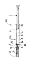
図1を参照すると、収容器具200と本発明による注射針アセンブリー1とを具えた本発明による注射器具100が示されている。収容器具200は、ほぼ筒状の形状を持つバレル8を具えている。ポリプロピレンおよびポリシクロオレフィンおよび/またはこれらを組み合わせたものを含むグループから選択される材料からバレル8を作ることができる。このような材料は、これらが長期間の製品の収容との相性が良いので好ましい。さらに、これらは通常、透明であり、従って収容された製品の量および品質の良好な視覚的評価を可能にする。
Referring to FIG. 1, there is shown an
バレル8は末端部8aと基端部8bとを有し、これは製品4を収容するチャンバ9を画成する。製品4は、患者に注射をするのに適した薬剤の如き任意の製品であってよい。製品4は、これが注射される前に収容器具200内に収容されることが好ましい。
図1の注射器具100はまた、ピストン2も具えており、このピストンは、例えば製品4を注射するために、前記ピストン2に加えられる末端側への力と、注射ストロークに沿ったピストン2の移動とにより、バレル8の末端部8aを通って製品4を押し出すようになっている。この観点において、図1の注射器具100のピストン2は、製品4を注射すべく前記ピストン2が末端方向に移動するように手動で駆動することができる中空のプランジャーロッド3の末端部に対し、例えばねじ止めによって固定される。
The
代わりに、図示しない本発明の一実施形態において、ピストン2をプランジャーロッド3の末端部にスナップ止めすることができる。
Alternatively, the
図1に示した位置から明らかなように、この収容器具200は、製品4を事前充填することができ、ピストン2はバレル8の基端部8bをシールする。
As can be seen from the position shown in FIG. 1, the receiving
図示しない一実施形態において、ピストン2は自立性ピストンである。換言すれば、このような一実施形態において、ピストン2はそのままであって、プランジャーロッドの如き駆動手段には全く結合されていない。好ましくは、この自立性ピストン2は変形可能であり、これを径方向に圧縮する通気管(図示せず)によって、これをバレル8に挿入することができる。これがバレル8に差し込まれて通気管を出ると、径方向の圧力が解放され、自立性ピストン2は、これがバレル8の内壁に対するその側面の摩擦によって動かずに自立するまで、膨張する。このような位置において、自立性ピストン2はバレル8の基端部8bをシールし、製品4をかなりの間、この方法にて収容することができる。
In one embodiment not shown, the
この注射器具100が製品4の長期収容に供されるので、製品4の時間超過および/または製品4の交換のあらゆる損失を阻止するため、すべての接触面が不透過性であることが重要である。特に、このピストン2は、これが自立性であるか否かに拘らず、ASTM標準記号E96-93に従って測定される水蒸気透過率により表されると共に特徴付けられる低水透過割合を持った材料から作られることが好ましい。この材料は、ゴム状材料であってよく、ハロブチルゴムから好ましくは選択される。ハロブチルゴムは、低い水透過割合を示すゴム状材料であり、これらは長期間収容される製品の良好な安定性に寄与する。さらに、ピストン2が室温で1日当たり3g.mm/m2以下、好ましくは室温で1日当たり1g.mm/m2以下、より好ましくは室温で1日当たり0.5g.mm/m2以下の水透過割合を持つ材料で作られていることもまた、好ましい。従って、ピストン2は外部への水蒸気の透過を阻止する。
Since this
このような材料で作られるこのようなピストン2はまた、バレル8の外側への製品4の如何なる漏洩をも阻止する場合に極めて有効である。
Such a
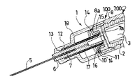
図1の注射器具100の注射針アセンブリー1の特徴は、注射器具100が収容位置から注射器具100を処分する可能性のある使用終了位置まで使用した場合の前記注射針アセンブリー1を構成する要素の相対的位置を示す図2から図5において、より明瞭に表されている。
The
これらの図に示すように、注射針アセンブリー1は、注射針ハブ6を具えている。図示された実施形態に関し、この注射針ハブ6は、注射針5を収容する管の形態による注射針支承部7と、壊れやすい部分7aにより注射針5を収容する管の基端部に結合され、フランジ10の形態による径方向壁部とを有し、壊れやすい部分の使用法は後で説明されよう。図1〜図5の注射針ハブ6のフランジ10は、以下に記述されるシール手段15と共に前記注射針ハブ6の立体投影図である図14において、より明瞭に表されている。
As shown in these figures, the
代わりに、注射針ハブ6の径方向壁部は、複数の、図15に示した実施形態では4つの径方向突起部19の形態を取ることができる。
Alternatively, the radial wall of the
注射針ハブ6が硬質材料で少なくとも部分的に作られていることが好ましい。例えば、注射針ハブ6は、ゴムと、ポリプロピレン,ポリエチレンの如き熱可塑性ポリマーと、その類似物とを含むグループから選択される材料で作られている。上図2〜図5に示した実施形態において、注射針ハブ6は、注射針支承部7と同様に、ポリプロピレンから作られており、ショアDで50以上の硬度を示す。
The
図2から図5に示すように、注射針アセンブリー1はまた、図示実施形態においてプラグ15の形態によるシール手段を具え、このシール手段は、チャンバ9の末端部9aを注射針ハブ6の注射針支承部7に対して緊密にシールするようになっている。このプラグ15は変形可能であって、ゴム状材料から作られていることが好ましく、前記ゴム状材料は、ゴムと、熱可塑性エラストマーと、これらの任意の組み合わせと、これらの類似物とを含むグループから選択されることがより好ましい。図示実施形態において、プラグ15はオレフィンベースの熱可塑性エラストマーで作られており、これはショアAで30から80までに広がる硬度を示す。
As shown in FIGS. 2 to 5, the
従って、注射針支承部7を含む注射針ハブ6およびプラグ15は、異なる特性の硬度と剛性とを有する2種類の異なる材料で作られている。特に、注射針ハブ6および注射針支承部7を構成する第1の材料の硬度および剛性は、プラグ15を構成する第2の材料の硬度および剛性よりも高い。この硬度および剛性の特性の相違は、個々の要素、すなわち一方において注射針支承部7および他方においてプラグ15がそれ自身の機能を最適な方法で発揮することを可能にする。
Accordingly, the
本発明の注射針アセンブリーのシール手段15は、図2に示すように、前記製品4が露出位置に収容されるチャンバ9の末端部9aから注射針支承部7へと注射製品4の漏洩を回避することを可能にする。従って、このシール手段15は、製品4の透過を減少させる。さらに、シール手段15は、チャンバ9内の製品4に対する外部からの汚染を阻止することが可能である。
As shown in FIG. 2, the sealing means 15 of the injection needle assembly of the present invention avoids leakage of the injection product 4 from the
好ましくは、シール手段15は、室温で1日当たり3g.mm/m2以下、好ましくは室温で1日当たり1g.mm/m2以下、より好ましくは室温で1日当たり0.5g.mm/m2以下の水透過割合を持つ材料で作られている。従って、このようなシール手段15は、製品4の長期収容を可能にする。さらに、このシール手段の存在とその特質とのおかげで、製品4を長期に亙り優れた安定性で収容することができる。 Preferably, sealing means 15, per day 3G.Mm/m 2 or less at room temperature, preferably 1 day 1G.Mm/m 2 or less at room temperature, 1 day 0.5G.Mm/m 2 or less and more preferably at room temperature Made of material with a water permeation rate of. Therefore, such a sealing means 15 enables long-term accommodation of the product 4. Furthermore, thanks to the presence and the nature of this sealing means, the product 4 can be accommodated with excellent stability over a long period of time.
シール手段15および注射針ハブ6は、これらの個々の境界の中間にある製品4のあらゆる漏洩を回避するため、相互に物理的に結合されていることが好ましい。例えば、図2〜図5に示した実施形態において、プラグ15および注射針ハブ6は複数材料の同時成形部品である。従って、2つの部品、すなわち一方のプラグ15と他方の注射針ハブ6との境界での製品4の漏洩が回避される。
The sealing means 15 and the
図2から図5に示すように、注射針アセンブリー1はまた、バレル8の末端部8aに適合する先端18を具えている。この先端18は、図2から図4に示すような注射針5の露出位置において、注射針支承部7と、壊れやすい部分7aと、シール手段15とを支持する。この先端18は、その内壁に当接部を形成する環状の凸部11を具えている。この環状の凸部11は、バレル8の末端部8aと共に、注射針ハブ6のフランジ10が図2および図3に示すような露出位置においてスナップ止めされる環状溝14を形成する。従って、バレル8の末端部8aと、注射針ハブ6のフランジ10と、先端18と、その環状の凸部11とは、係合手段を全体として形成し、露出位置において注射針ハブ6をバレル8の末端部8aに固定するようになっている。
As shown in FIGS. 2 to 5, the
代わりに、図示しない本発明の一実施形態において、バレル8は係合手段の環状溝にスナップ止めされるようになっている径方向壁部を具えることができる。例えば、注射針ハブ6は、その内壁に当接部を画成する環状溝を具えることができ、この当接部はバレル8の内壁に設けられた径方向壁部を収容するようになっている。このような実施形態はまた、露出位置におけるバレル8の末端部8aに注射針ハブ6を固定することも確実にする。
Alternatively, in one embodiment of the invention not shown, the
図2から明らかなように、注射針ハブ6の壊れやすい部分7aは、係合手段8a,10,11,18と注射針支承部7との間に配されている。この注射針支承部7は、図2および図3に示した注射針5の露出位置と、前記注射針5がバレル8内に隠される図5に示した格納位置との間を移動可能である。壊れやすい部分7aは、これが破壊された場合、注射針5の前記露出位置と前記格納位置との間の前記係合手段8a,10,11,18に対して前記注射針支承部7の独立した基端側への変位を可能とするようになっている。
As is apparent from FIG. 2, the
図示しない本発明の一実施形態において、壊れやすい部分7aとシール手段15とが一体的に組み合わされ、すなわちこれらは、依然として異なる硬度と剛性との特性を持った1つの要素を形成する。
In an embodiment of the invention not shown, the
図2〜図5の注射針アセンブリー1は、注射針ハブ6の注射針支承部7の注射針5を収容するための管を収容するスリーブ17をさらに具える。このスリーブ17は、壊れやすい部分7aの方を向く切断面16をその基端部に具え、露出位置における前記注射針支承部7に対して固定して配されるようになっている。これらの切断面16は、壊れやすい部分7aの切り離し手段を形成する。
The
図2から図5に示すように、らせん形のばね12がスリーブ17と注射針支承部7との間に配され、前記ばね12の基端部が壊れやすい部分7aに押し当たると共に前記ばね12の末端部が先端18の末端領域の内壁に画成された径方向ストッパ13に押し当たる。
As shown in FIGS. 2 to 5, a
さて、本発明の器具100の使用法が図1から図5を参照して説明されよう。
The use of the
格納位置にある図1および図2に示すような本発明の器具100が使用者に与えられる。この位置において、上記した本発明の注射針アセンブリー1は、露出位置にある注射針5を具えている。あらゆる偶発的な突き刺しを回避するため、注射針アセンブリー1は、注射針5を保護するための注射針カバー24をさらに具えていることが好ましい。注射針カバー24は、注射針5の滅菌状態を維持すると共に製品4が注射針5により画成される通路を通ってチャンバ9からの漏洩するのを阻止するゴムプラグを好ましくは具えている。この位置において、ばね12は圧縮状態にあり、従ってこれは係合手段8a,10,11,18と注射針支承部7との間に配されて、前記注射針支承部7が前記係合手段8a,10,11,18から基端方向に離れて動くようにする付勢手段を構成する。けれども、図1および図2に示した位置において、この付勢手段は機能していない。
A user is provided with the
使用者は注射針カバー24を取り外し、プランジャーロッド3に末端部側への力を加えることにより注射の段階に進み、ピストン2を注射針アセンブリー1の末端部に向けて移動させて製品4の注射を行うようになっている。
The user removes the
注射の終りにて、図3に示すようにピストン2はプラグ15と接触状態になる。壊れやすい部分7aは、注射の終りにてピストン2により、特に注射の終りにて前記ピストン2に加えられる付加的な末端側への力の影響により、末端側に移動可能なようになっている。この付加的な力は、注射針ハブ6のフランジ10を係合手段8a,11から係合解除するために必要であり、壊れやすい部分7aの末端側への変位を可能とする。この付加的な力は、切り離し手段16の早すぎる作動を阻止するのに充分大きい。チャンバ9内の圧力増大に対して係合手段8a,10,11,18がこのシステムのすべての早すぎる作動を阻止するようになっていることに注意すべきである。これらはまた、許容可能な、すなわち実質的に充分であって大きすぎないここに記述された安全システムを作動させるための力をもたらすように設定される。
At the end of the injection, the
従って、使用者はさらにプランジャーロッド3を押圧し、前記壊れやすい部分7aがスリーブ17の切断面16と接触状態になるまで、この壊れやすい部分7aが末端側に移動することをピストン2にもたらす。前記壊れやすい部分7aが図4に示すように末端側に移動するので、切断面16は、壊れやすい部分7aを破壊する切り離し手段として機能する。プランジャーロッド3に、従ってピストン2に加えられるさらなる末端側の力により、シール手段、すなわちプラグ15と、そしてピストン2それ自身は、図4に示すように、切断面16によって連続的に切断される。従って、一度破壊されると、壊れやすい部分7aはバレル8の独立した基端側への変位を可能にする。
Accordingly, the user further presses the
結果として、ばね12の基端部は壊れやすい部分7aによってすでに保持されておらず、それで前記ばね12はその休止位置に戻ろうとする。これは、基端方向に伸張して注射針支承部7と注射針5とを引き込む。従って、注射針5は、図5に示すように、注射針支承部7と共にプランジャーロッド3の内側に引き込まれる。結局、注射針5は格納位置にある。この位置における器具100は安全である。注射針5は、もはや露出しておらず、偶発的な突き刺しが阻止される。注射器具100を処分することができる。
As a result, the proximal end of the
図6および図7には、図1から図5に示した注射針アセンブリー1の変形例が示されており、シール手段15が末端方向に延在する長手方向スカート22を具えている。図1〜図5と同じ要素を示す参照符号が継続して用いられている。
FIGS. 6 and 7 show a variant of the
図6で見ることができるように、スカート22は、注射針ハブ6の基端領域の一部を収容し、これがバレル8の末端部8aに緊密に収容されるようになっている。特に、スカート22は、その末端部に径方向壁部23を具え、この径方向壁部は、バレルの末端部8aと先端18の内壁に画成された環状の凸部11とで形成される環状溝14に対し、図6に示した露出位置にてスナップ止めされる。従って、径方向壁部23と、バレル8の末端部8aと、環状の凸部11と、先端18とは、注射針ハブ6を露出位置にてバレル8の末端部8aに固定する係合手段を形成する。このような一実施形態において、係合手段の一部とシール手段とは一体的に組み合わされている。
As can be seen in FIG. 6, the
スカート22およびその径方向壁部23は、変形可能な材料で作られている。従って、スカート22は、図6に示す露出位置から図7に示す作動位置、すなわち切断位置までそれ自身を折り返すことが可能である。この位置において、ピストン2は、プランジャーロッド3に加えられる末端側への力の作用により、これがスリーブ17の切断面16と接触状態になるまで、注射針ハブ6の壊れやすい部分7aを末端側に動かす。この壊れやすい部分の末端側への変位中に、スカート22は、それ自身を折り返すように動き出し、末端側への力をプランジャーロッド3に加えている間、使用者がことを使用者が克服できるように、滑らかな摩擦力を与え、その結果としてピストン2の変位の良好な制御を可能とする前記末端部の力の減衰をもたらす。ピストン2に対するさらなる末端側への圧力により、切断面16が壊れやすい部分7aを切り離し、そしてシール手段15および最終的にはピストン2を切断し、同時に、スカート22は図7に示すようにそれ自身を完全に折り返す。
The
図7に示した状態に続く最終位置を示していない。これは、ばね12がその休止位置に戻り、注射針支承部7と注射針5とを基端方向に引き込んだ後、注射針5がプランジャーロッド3内に隠れる格納位置に対応する。
The final position following the state shown in FIG. 7 is not shown. This corresponds to a retracted position where the
図示しない本発明の他の一実施形態において、スカート22は基端方向に延在することができる。
In another embodiment of the present invention (not shown), the
図10および図11には図6および図7の実施形態の一変形例が示されており、スカート22は、それ自身が折り返されないけれども、その外壁に環状の突起27が設けられ、この突起は図10に示すような露出位置において、先端18の基端部とバレル8の内壁に画成された当接部28との間にスナップ止めされる。図1〜図7と同じ要素を示す参照符号が継続して用いられている。
FIGS. 10 and 11 show a variant of the embodiment of FIGS. 6 and 7 in which the
図8および図9には本発明の注射針アセンブリー1の一変形例が示されており、係合手段は、バレル8によって少なくとも部分的に画成された環状溝14に露出位置にてスナップ止めされるようになっている径方向壁部を具え、前記径方向壁部は注射針ハブ6に画成した複数の径方向突起部であり、これら径方向突起部は、末端方向に延在する複数の長手方向可撓性脚部21の末端部20を形成している。図1〜図5と同じ要素を示す参照符号が継続して用いられている。
FIGS. 8 and 9 show a variant of the
代わりに、図示しない本発明の一実施形態において、径方向突起部は基端方向に延在する複数の長手方向可撓性脚部の基端部を形成している。 Instead, in one embodiment of the present invention (not shown), the radial protrusions form proximal ends of a plurality of longitudinal flexible legs extending in the proximal direction.
図8および図9から見ることができるように、端部20が変形可能な材料で作られている。図8に示した露出位置において、これらの端部20は、前記先端18とバレル8の末端部8aとで画成される環状の凸部11によって形成された環状溝14にスナップ止めされる。従って、端部20と、環状の凸部11と、バレル8の末端部8aと、先端18とは、注射針ハブ6を露出位置にてバレル8の末端部8aに固定する係合手段を形成する。
As can be seen from FIGS. 8 and 9, the
図9は、切断位置における図8の実施形態を示しており、長手方向可撓性脚部21の端部20は、使用者によりプランジャーロッド3に加えられる末端側への力によって、末端側に押されるピストン2の末端側への圧力により、環状の凸部11をいったん乗り越えている。
FIG. 9 shows the embodiment of FIG. 8 in a cutting position, where the
そして、スリーブ17の切断面16が壊れやすい部分7aを破壊し、シール手段15およびピストン2を切断する。
Then, the
注射針5は、従前の実施形態にて記述したように、その休止位置に戻るばね12の動作によってプランジャーロッド3内に引き込まれる。
The
図12には、図1〜図11の注射器具100のピストン2が前記注射器具100の注射針アセンブリー1の末端に向けて移動して製品4を注射することをもたらす駆動手段として好適であるプランジャーロッド3が示されている。この図のプランジャーロッド3は中空であり、注射針5を例えばすでに図5に示したような格納位置に収容するようになっている。この図に関し、前記プランジャーロッド3の末端部25は開口している。
FIG. 12 shows a plan that is suitable as a driving means for causing the
図13には、図12の中空のプランジャーロッド3の一変形例が示されており、前記プランジャーロッド3の末端部25は、切り離し手段16が注射の終りに前記プランジャーロッド3に加えられる末端側への力の作用により前記ピストン2を切断するため、前記ピストン2がそれ自身を前記プランジャーロッド3内に変形するのを阻止するように、ピストン2のための径方向支承面を形成するようになっている支持手段を具えている。支持手段はまた、ピストン2のきれいな切断をもたらし、従って注射針5のための良好な通路をもたらすことにも役立つ。図13に示した実施形態に関し、支持手段は径方向壁部26を具えており、この実施形態において、これは十字形状を形成する複数の径方向延在部を画成する。壊れやすい部分7aを切断した後、シール手段15と、ピストン2と、切り離し手段の切断面16とは、これらの径方向延在部をも切断し、注射針5がプランジャーロッド3内に引き込まれることを可能にする。
FIG. 13 shows a variation of the
本発明の注射針アセンブリー1は、一体化された安全システムを持つ事前充填可能な注射器具100の製造を可能にする。従って、本発明の注射器具100は、看護婦の如きエンドユーザによる最終製品としても、製薬会社によって例えば充填および/または封止処理中に製造される製品としても、共に安全かつ小型であって取り扱いが容易である。
The
Claims (39)
末端部(8a)および基端部(8b)を有し、前記製品(4)を収容するためのチャンバ(9)を画成するほぼ筒状のバレル(8)と、
末端側への力を加えることにより前記製品(4)が末端部(8a)を通って排出されるようになっているピストン(2)と
を少なくとも具え、この注射針アセンブリー(1)は、
注射針(5)を収容するようになっており、前記注射針(5)が露出する露出位置と前記注射針(5)が前記バレル(8)に隠される格納位置との間を移動可能であり、注射針ハブ(6)により支えられ、前記注射針ハブ(6)と共に第1の材料で作られた注射針支承部(7)と、
前記注射針支承部(7)を少なくとも前記露出位置にて前記バレル(8)の前記末端部(8a)に固定するようになっている係合手段(8a,10,11,18,19,20,23)と
を少なくとも具え、
前記チャンバ(9)の末端部(9a)を前記注射針支承部(7)に対して緊密にシールし、前記チャンバ(9)の末端部(9a)から少なくとも前記露出位置における注射針支承部(7)への前記注射可能な製品(4)のあらゆる漏洩を回避すると共に製品の透過を減らすようになっており、第2の材料で作られたシール手段(15)と、
前記係合手段(8a,10,11,18,19,20,23)と前記注射針支承部(7)との間に配され、破壊された場合に前記露出位置と前記格納位置との間の前記係合手段(8a,10,11,18,19,20,23)に対して前記注射針支承部(7)の基端側への独自の変位を可能にするようになっている壊れやすい部分(7a)と
を具え、前記シール手段(15)が前記チャンバ(9)と前記壊れやすい部分(7a)との間に配され、前記第1の材料が前記第2の材料よりも硬質であることを特徴とする注射針アセンブリー(1)。 A needle assembly (1) adapted to be used in combination with a storage device (200) of a product (4), wherein the storage device (200) has a distal end portion (8a) and a proximal end portion (8b). A substantially cylindrical barrel (8) defining a chamber (9) for containing the product (4);
The needle assembly (1) comprises at least a piston (2) adapted to expel the product (4) through the distal end (8a) by applying a distal force.
The injection needle (5) is accommodated, and is movable between an exposed position where the injection needle (5) is exposed and a storage position where the injection needle (5) is hidden by the barrel (8). A needle support (7) supported by the needle hub (6) and made of a first material together with the needle hub (6);
Engaging means (8a, 10, 11, 18, 19, 20) adapted to fix the injection needle support (7) to the end (8a) of the barrel (8) at least in the exposed position. , 23) and at least
The distal end portion (9a) of the chamber (9) is tightly sealed with respect to the injection needle support portion (7), and the injection needle support portion (at least in the exposed position) from the end portion (9a) of the chamber (9). 7) avoiding any leakage of said injectable product (4) and reducing the permeation of the product, sealing means (15) made of a second material;
Arranged between the engaging means (8a, 10, 11, 18, 19, 20, 23) and the injection needle support portion (7), and when broken, between the exposed position and the retracted position. Breakage adapted to allow a unique displacement of the injection needle support (7) towards the proximal end relative to the engagement means (8a, 10, 11, 18, 19, 20, 23) And the sealing means (15) is disposed between the chamber (9) and the fragile part (7a), and the first material is harder than the second material. A needle assembly (1) characterized in that
前記注射針アセンブリー(1)は、前記壊れやすい部分(7a)の方に向けられ、露出位置の前記注射針支承部(7)に対して固定して配されるようになっている切り離し手段(16)を具え、これが末端側へ移動した場合に前記壊れやすい部分(7a)を破壊し、注射針支承部(7)の基端側への変位を可能にするようになっていることを特徴とする請求項1に記載の注射針アセンブリー(1)。 At least the fragile part (7a) is movable to the end side by the piston (2) at the end of one injection stroke,
The needle assembly (1) is directed to the fragile part (7a) and is detachable means (7) arranged to be fixed to the needle support part (7) in the exposed position. 16), which breaks the fragile portion (7a) when it moves to the distal side, and allows the needle support portion (7) to be displaced toward the proximal side. 2. The needle assembly (1) according to claim 1.
末端部(8a)および基端部(8b)を有し、前記製品(4)を収容するためのチャンバ(9)を画成するほぼ筒状をなすバレル(8)と、
末端側への力を加えることにより前記製品(4)が末端部(8a)を通って排出されるようになっているピストン(2)と
を少なくとも具え、前記収容器具(200)が前記製品(4)を事前充填可能であって、前記ピストン(2)が前記バレル(8)の基端部(8b)をシールしていることを特徴とする請求項28に記載の注射器具(100)。 The container (200) has a distal end (8a) and a proximal end (8b), and a substantially cylindrical barrel (8) defining a chamber (9) for accommodating the product (4) When,
A piston (2) adapted to discharge the product (4) through the distal end (8a) by applying a force to the distal side, and the receiving device (200) comprises the product ( 29. Injection device (100) according to claim 28, characterized in that 4) can be prefilled and the piston (2) seals the proximal end (8b) of the barrel (8).
Applications Claiming Priority (3)
| Application Number | Priority Date | Filing Date | Title |
|---|---|---|---|
| FR06/03720 | 2006-04-26 | ||
| FR0603720A FR2900344B1 (en) | 2006-04-26 | 2006-04-26 | INJECTION DEVICE WITH RETRACTABLE NEEDLE |
| PCT/IB2007/001980 WO2007125419A2 (en) | 2006-04-26 | 2007-04-26 | Injection device with retractable needle |
Publications (3)
| Publication Number | Publication Date |
|---|---|
| JP2009534152A JP2009534152A (en) | 2009-09-24 |
| JP2009534152A5 JP2009534152A5 (en) | 2010-04-15 |
| JP5373600B2 true JP5373600B2 (en) | 2013-12-18 |
Family
ID=37695898
Family Applications (1)
| Application Number | Title | Priority Date | Filing Date |
|---|---|---|---|
| JP2009507194A Active JP5373600B2 (en) | 2006-04-26 | 2007-04-26 | Injection device with retractable needle |
Country Status (7)
| Country | Link |
|---|---|
| US (1) | US9259537B2 (en) |
| EP (1) | EP2012855B1 (en) |
| JP (1) | JP5373600B2 (en) |
| CN (1) | CN101466425B (en) |
| ES (1) | ES2560640T3 (en) |
| FR (1) | FR2900344B1 (en) |
| WO (1) | WO2007125419A2 (en) |
Families Citing this family (21)
| Publication number | Priority date | Publication date | Assignee | Title |
|---|---|---|---|---|
| US8808246B2 (en) | 2009-07-21 | 2014-08-19 | The General Hospital Corporation | Peripheral blood sampling methods and devices |
| US8323249B2 (en) | 2009-08-14 | 2012-12-04 | The Regents Of The University Of Michigan | Integrated vascular delivery system |
| WO2011146769A2 (en) | 2010-05-19 | 2011-11-24 | Tangent Medical Technologies Llc | Integrated vascular delivery system |
| WO2011146772A1 (en) | 2010-05-19 | 2011-11-24 | Tangent Medical Technologies Llc | Safety needle system operable with a medical device |
| US8366685B2 (en) | 2011-04-26 | 2013-02-05 | Creative Vascular, Llc | Systems and methods for phlebotomy through a peripheral IV catheter |
| US10076272B2 (en) | 2011-04-26 | 2018-09-18 | Velano Vascular, Inc. | Systems and methods for phlebotomy through a peripheral IV catheter |
| US9186100B2 (en) | 2011-04-26 | 2015-11-17 | Velano Vascular, Inc. | Systems and methods for phlebotomy through a peripheral IV catheter |
| ITMI20120016A1 (en) * | 2012-01-09 | 2013-07-10 | Biosynth Srl | SYRINGE FOR INJECTIONS OR WITHDRAWALS |
| ES2856216T3 (en) * | 2013-10-28 | 2021-09-27 | Becton Dickinson Co | Leak-free stopper for a syringe assembly that has low breakout and holding forces |
| JP6461174B2 (en) | 2014-02-04 | 2019-01-30 | アイシーユー・メディカル・インコーポレーテッド | Self-priming system and self-priming method |
| US10232110B2 (en) * | 2014-07-08 | 2019-03-19 | Becton, Dickinson And Company | Fluid transfer device or set with retractable needle and septum |
| EP3213786A4 (en) * | 2014-10-30 | 2018-07-11 | Chugai Seiyaku Kabushiki Kaisha | Pre-filled syringe preparation with needle, which is equipped with syringe cap |
| EP3275485A4 (en) * | 2015-03-26 | 2018-06-27 | Terumo Kabushiki Kaisha | Syringe cap, syringe assembly, and prefilled syringe |
| US10369292B2 (en) * | 2016-01-15 | 2019-08-06 | W. L. Gore & Associates, Inc. | Syringe plunger assemblies |
| US10300247B2 (en) | 2016-02-03 | 2019-05-28 | Velano Vascular, Inc. | Devices and methods for fluid transfer through a placed peripheral intravenous catheter |
| FR3052690B1 (en) * | 2016-06-20 | 2018-06-22 | Aptar France Sas | DEVICE FOR DISPENSING FLUID PRODUCT. |
| US9744344B1 (en) | 2016-06-30 | 2017-08-29 | Velano Vascular, Inc. | Devices and methods for catheter placement within a vein |
| EP4059556A1 (en) | 2017-03-21 | 2022-09-21 | Velano Vascular, Inc. | Methods for controlling catheter device size |
| CN110430914B (en) | 2017-03-21 | 2022-03-01 | 威蓝诺血管股份有限公司 | Device for fluid delivery through a placed peripheral venous catheter |
| EP4017571A4 (en) | 2019-08-20 | 2023-11-29 | Velano Vascular, Inc. | Fluid transfer devices with extended length catheters and methods of using the same |
| WO2022115653A1 (en) | 2020-11-26 | 2022-06-02 | Avia Vascular, Llc | Blood collection devices, systems, and methods |
Family Cites Families (9)
| Publication number | Priority date | Publication date | Assignee | Title |
|---|---|---|---|---|
| US5578011A (en) * | 1995-05-11 | 1996-11-26 | Shaw; Thomas J. | Tamperproof retractable syringe |
| US5632733A (en) * | 1995-05-11 | 1997-05-27 | Shaw; Thomas J. | Tamperproof retractable syringe |
| JP3835882B2 (en) * | 1997-03-31 | 2006-10-18 | テルモ株式会社 | Indwelling needle assembly |
| AU723060B3 (en) * | 2000-02-22 | 2000-08-17 | Occupational & Medical Innovations Ltd | A single use syringe |
| US6689106B2 (en) * | 2000-07-31 | 2004-02-10 | Becton Dickinson And Company | Retracting needle assembly for a syringe |
| FR2839892B1 (en) * | 2002-05-27 | 2005-03-18 | Mb Innovation | INJECTION DEVICE FOR SINGLE USE INTENDED FOR PRE-FILLING |
| CA2412409C (en) * | 2002-11-20 | 2007-01-23 | Ming-Jeng Shue | Disposable syringe |
| US7604613B2 (en) * | 2004-01-20 | 2009-10-20 | Beckton, Dickinson And Company | Syringe having a retractable needle |
| CA2584106C (en) * | 2004-10-14 | 2011-09-06 | Safety Medical International, Incorporated | Safety medical syringe with retractable needle |
-
2006
- 2006-04-26 FR FR0603720A patent/FR2900344B1/en active Active
-
2007
- 2007-04-26 JP JP2009507194A patent/JP5373600B2/en active Active
- 2007-04-26 CN CN200780021670XA patent/CN101466425B/en active Active
- 2007-04-26 US US12/298,647 patent/US9259537B2/en active Active
- 2007-04-26 EP EP07734992.6A patent/EP2012855B1/en active Active
- 2007-04-26 ES ES07734992.6T patent/ES2560640T3/en active Active
- 2007-04-26 WO PCT/IB2007/001980 patent/WO2007125419A2/en active Application Filing
Also Published As
| Publication number | Publication date |
|---|---|
| CN101466425A (en) | 2009-06-24 |
| US20110015577A1 (en) | 2011-01-20 |
| ES2560640T3 (en) | 2016-02-22 |
| JP2009534152A (en) | 2009-09-24 |
| CN101466425B (en) | 2013-01-23 |
| WO2007125419A3 (en) | 2008-01-24 |
| EP2012855A2 (en) | 2009-01-14 |
| WO2007125419A2 (en) | 2007-11-08 |
| FR2900344B1 (en) | 2009-02-27 |
| US9259537B2 (en) | 2016-02-16 |
| EP2012855B1 (en) | 2015-11-11 |
| FR2900344A1 (en) | 2007-11-02 |
Similar Documents
| Publication | Publication Date | Title |
|---|---|---|
| JP5373600B2 (en) | Injection device with retractable needle | |
| JP5175838B2 (en) | Automatic injection device | |
| AU779820B2 (en) | Retracting needle syringe | |
| JP5202529B2 (en) | Automatic injection device with temporary means | |
| US6517516B1 (en) | Method of making a retracting needle syringe | |
| CN105324143B (en) | Piston for syringe with sealing structure of specific dimensional proportion | |
| US4378015A (en) | Automatic injecting syringe | |
| US20140288498A1 (en) | Dual Chamber Passive Retraction Needle Syringe | |
| JPH07511A (en) | Syringe assembly with isolating device for needle | |
| KR20050025179A (en) | Safety injectors | |
| JP2002503126A (en) | Improved syringe with wicking means | |
| ES2894827T3 (en) | Automatic injection device with timing means |
Legal Events
| Date | Code | Title | Description |
|---|---|---|---|
| A521 | Request for written amendment filed |
Free format text: JAPANESE INTERMEDIATE CODE: A523 Effective date: 20100225 |
|
| A621 | Written request for application examination |
Free format text: JAPANESE INTERMEDIATE CODE: A621 Effective date: 20100225 |
|
| A977 | Report on retrieval |
Free format text: JAPANESE INTERMEDIATE CODE: A971007 Effective date: 20111222 |
|
| A131 | Notification of reasons for refusal |
Free format text: JAPANESE INTERMEDIATE CODE: A131 Effective date: 20111227 |
|
| A601 | Written request for extension of time |
Free format text: JAPANESE INTERMEDIATE CODE: A601 Effective date: 20120323 |
|
| A602 | Written permission of extension of time |
Free format text: JAPANESE INTERMEDIATE CODE: A602 Effective date: 20120330 |
|
| A601 | Written request for extension of time |
Free format text: JAPANESE INTERMEDIATE CODE: A601 Effective date: 20120425 |
|
| A602 | Written permission of extension of time |
Free format text: JAPANESE INTERMEDIATE CODE: A602 Effective date: 20120507 |
|
| A02 | Decision of refusal |
Free format text: JAPANESE INTERMEDIATE CODE: A02 Effective date: 20121130 |
|
| A521 | Request for written amendment filed |
Free format text: JAPANESE INTERMEDIATE CODE: A523 Effective date: 20130326 |
|
| RD13 | Notification of appointment of power of sub attorney |
Free format text: JAPANESE INTERMEDIATE CODE: A7433 Effective date: 20130327 |
|
| A521 | Request for written amendment filed |
Free format text: JAPANESE INTERMEDIATE CODE: A821 Effective date: 20130327 |
|
| A911 | Transfer to examiner for re-examination before appeal (zenchi) |
Free format text: JAPANESE INTERMEDIATE CODE: A911 Effective date: 20130417 |
|
| A131 | Notification of reasons for refusal |
Free format text: JAPANESE INTERMEDIATE CODE: A131 Effective date: 20130625 |
|
| A521 | Request for written amendment filed |
Free format text: JAPANESE INTERMEDIATE CODE: A523 Effective date: 20130708 |
|
| TRDD | Decision of grant or rejection written | ||
| A01 | Written decision to grant a patent or to grant a registration (utility model) |
Free format text: JAPANESE INTERMEDIATE CODE: A01 Effective date: 20130820 |
|
| A61 | First payment of annual fees (during grant procedure) |
Free format text: JAPANESE INTERMEDIATE CODE: A61 Effective date: 20130919 |
|
| R150 | Certificate of patent or registration of utility model |
Ref document number: 5373600 Country of ref document: JP Free format text: JAPANESE INTERMEDIATE CODE: R150 Free format text: JAPANESE INTERMEDIATE CODE: R150 |
|
| R250 | Receipt of annual fees |
Free format text: JAPANESE INTERMEDIATE CODE: R250 |
|
| R250 | Receipt of annual fees |
Free format text: JAPANESE INTERMEDIATE CODE: R250 |
|
| R250 | Receipt of annual fees |
Free format text: JAPANESE INTERMEDIATE CODE: R250 |
|
| R250 | Receipt of annual fees |
Free format text: JAPANESE INTERMEDIATE CODE: R250 |
|
| R250 | Receipt of annual fees |
Free format text: JAPANESE INTERMEDIATE CODE: R250 |
|
| R250 | Receipt of annual fees |
Free format text: JAPANESE INTERMEDIATE CODE: R250 |
|
| R250 | Receipt of annual fees |
Free format text: JAPANESE INTERMEDIATE CODE: R250 |