JP5371232B2 - Image processing apparatus and image processing method - Google Patents
Image processing apparatus and image processing method Download PDFInfo
- Publication number
- JP5371232B2 JP5371232B2 JP2007307892A JP2007307892A JP5371232B2 JP 5371232 B2 JP5371232 B2 JP 5371232B2 JP 2007307892 A JP2007307892 A JP 2007307892A JP 2007307892 A JP2007307892 A JP 2007307892A JP 5371232 B2 JP5371232 B2 JP 5371232B2
- Authority
- JP
- Japan
- Prior art keywords
- image
- frame
- adaptation
- low
- pass
- Prior art date
- Legal status (The legal status is an assumption and is not a legal conclusion. Google has not performed a legal analysis and makes no representation as to the accuracy of the status listed.)
- Expired - Fee Related
Links
Images


Landscapes
- Image Processing (AREA)
- Color Television Systems (AREA)
- Processing Of Color Television Signals (AREA)
- Compression Or Coding Systems Of Tv Signals (AREA)
Abstract
Description
本発明は画像処理装置および画像処理方法に関し、特に、時分割された複数のフレーム画像からなる動画像を再生する画像処理装置および画像処理方法に関する。 The present invention relates to an image processing apparatus and an image processing method, and more particularly to an image processing apparatus and an image processing method for reproducing a moving image composed of a plurality of time-divided frame images.
一般に人間の色知覚モデルは、人間の色の見えが正しく予測できるように設計されていおり、その代表的なものとしてカラーアピアランスモデルがある。このカラーアピアランスモデルは観察条件の変化に対応しており、観察条件パラメータとして、輝度、白色点、周囲相対輝度などの観察情報を設定できるため、観察条件が変わっても色の見えを適切に再現することができる。 In general, a human color perception model is designed so that the appearance of a human color can be correctly predicted. A typical example is a color appearance model. This color appearance model responds to changes in viewing conditions, and observation information such as brightness, white point, and ambient relative brightness can be set as viewing condition parameters, so that color appearance can be reproduced appropriately even when viewing conditions change. can do.
更に、カラーアピアランスモデルを拡張したモデルとして、人間の空間的視覚特性および時間的視覚特性が反映されたイメージアピアランスモデルが存在し、その代表的なものとしてiCAMが知られている。イメージアピアランスモデルにおいては、特に動画像の見えを予測する場合には、明順応や色順応の時間的視覚特性が反映される必要がある。 Furthermore, as an extended model of the color appearance model, there is an image appearance model reflecting human spatial visual characteristics and temporal visual characteristics, and iCAM is known as a representative one. In the image appearance model, particularly when predicting the appearance of a moving image, it is necessary to reflect the temporal visual characteristics of light adaptation and chromatic adaptation.
例えば、動画像に対しイメージアピアランスモデル(iCAM)を適用する技術が、例えば非特許文献1に記載されている。この文献には、以下のような技術が記載されている。まず、10秒前のフレーム画像から注目フレーム画像までのフレームに対するローパス画像、及びYローパス画像(絶対輝度画像)に対し、以下に示す(1)式によって算出した順応の重みを掛け合わせる。なお、(1)式においてAWは算出された重みを示し、fはフレーム番号を示す。すなわち、例えば1秒間に30フレームであれば、f=0で現在のフレーム番号、f=-300で10秒前のフレーム番号を示す。
For example, a technique for applying an image appearance model (iCAM) to a moving image is described in Non-Patent
次に、それら複数の重み付けられたローパス画像及びYローパス画像をそれぞれ合成することによって、注目フレームのローパス画像及びYローパス画像を生成する。そして、これらをiCAMのフレームワークで利用する事により、空間的かつ時間的な視覚特性を反映させた動画再生を行っている。
一般的な動画像において、被写体オブジェクトが複数存在することは当然であり、それぞれのオブジェクトは異なる特徴を有し、例えばそれぞれの描画時間は異なる。また、再生された動画像を鑑賞する際には通常、注目されるオブジェクト(注目オブジェクト)が存在する。 In a general moving image, there are naturally a plurality of subject objects, and each object has different characteristics. For example, each drawing time is different. In addition, when watching a reproduced moving image, there is usually an object that is noticed (object of interest).
上記非特許文献1に記載された技術によれば、フレーム画像全体に対して一様なアピアランス処理を行っていた。したがって、フレーム画像全体に対して一様に時間的視覚特性等が反映されるため、注目オブジェクトごとに時間的視覚特性を適用することができなかった。
According to the technique described in Non-Patent
この例を図12を用いて説明する。図12において、観察者が車Aを注目オブジェクトとして、iCAMが適用される10秒より前の開始0秒より車Aを見続けているとする。この場合、120秒後のフレーム画像に対する車Aは完全順応に近い状態であり、車Aに対する順応の重みは1に近い高い値になっているはずである。しかしながら、上記非特許文献1に記載された方法によればこの場合、フレーム画像全体に時間的視覚特性が反映され、車Aの位置は移動していくため、順応の重みは低い値となってしまう。更に、図12において車Bを注目オブジェクトとした場合、上記従来の方法によれば、実際の車Bの観察時間よりも長い順応時間が適用され、車Bに対する順応の重みは高い値になってしまう。
This example will be described with reference to FIG. In FIG. 12, it is assumed that the observer keeps watching the car A from the
本発明は上述した問題を解決するためになされたものであり、以下の機能を有する画像処理装置および画像処理方法を提供することを目的とする。すなわち、フレーム画像内のオブジェクト画像ごとに適切な時間的視覚特性を適用した色変換を行う。 SUMMARY An advantage of some aspects of the invention is to provide an image processing apparatus and an image processing method having the following functions. That is, color conversion is performed by applying an appropriate temporal visual characteristic for each object image in the frame image.
上記目的を達成するための一手段として、本発明の画像処理装置は以下の構成を備える。 As a means for achieving the above object, an image processing apparatus of the present invention comprises the following arrangement.
すなわち、人間の空間的視覚特性及び時間的視覚特性を反映させるように、時分割された複数のフレーム画像からなる動画像を再生する画像処理装置であって、前記複数のフレーム画像内の注目フレーム画像からオブジェクト画像を抽出するオブジェクト抽出手段と、前記注目フレームまでの予め定められた処理期間内において、前記抽出したオブジェクト画像ごとのオブジェクト順応時間を取得するオブジェクト順応時間取得手段と、前記オブジェクト画像ごとに、前記オブジェクト順応時間に基づいてオブジェクト順応特徴量を算出するオブジェクト順応特徴量の算出手段と、前記注目フレーム画像に対し、前記オブジェクト画像ごとに前記オブジェクト順応特徴量に基づく色変換を行う色変換手段と、を有することを特徴とする。 That is, an image processing apparatus that reproduces a moving image composed of a plurality of time-divided frame images so as to reflect human spatial visual characteristics and temporal visual characteristics, wherein the frame of interest in the plurality of frame images An object extraction means for extracting an object image from an image, an object adaptation time acquisition means for acquiring an object adaptation time for each of the extracted object images within a predetermined processing period until the frame of interest, and for each object image In addition, an object adaptation feature amount calculating unit that calculates an object adaptation feature amount based on the object adaptation time, and a color conversion that performs color conversion based on the object adaptation feature amount for each object image with respect to the target frame image And means.
以上の構成からなる本発明によれば、フレーム画像内のオブジェクト画像ごとに適切な時間的視覚特性を適用した色変換を行うことが可能となる According to the present invention having the above configuration, it is possible to perform color conversion applying an appropriate temporal visual characteristic for each object image in the frame image.
以下、添付の図面を参照して、本発明をその好適な実施形態に基づいて詳細に説明する。なお、以下の実施形態において示す構成は一例に過ぎず、本発明は図示された構成に限定されるものではない。 Hereinafter, the present invention will be described in detail based on preferred embodiments with reference to the accompanying drawings. The configurations shown in the following embodiments are merely examples, and the present invention is not limited to the illustrated configurations.
<第1実施形態>
●装置構成
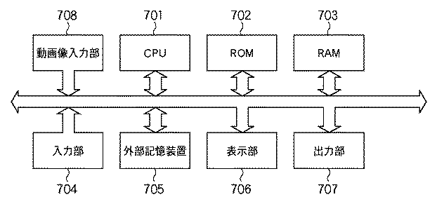
図1は、本実施形態に係る画像処理装置のブロック構成例を示す図である。同図において、CPU701は、ROM702及びハードディスク等の外部記憶装置705、等に格納されたプログラムに従い、RAM703をワークメモリに利用して、装置全体の動作を司る。CPU701はさらに、本実施形態におけるカラーマッチングに関連する処理をはじめとする各種の画像処理を実行する。
<First Embodiment>
Apparatus Configuration FIG. 1 is a diagram illustrating a block configuration example of an image processing apparatus according to the present embodiment. In the figure, a
入力部704は、キーボードやマウスなどの入力デバイス及びその入力インターフェイスを示し、操作者からの入力指示を受け取る。表示部706は、モニタなどの表示デバイス及びビデオインターフェイスを示し、動画像の表示、本実施形態に関わるユーザインターフェィスの画面を表示する。出力部707は、プリンタなどの出力デバイス及び出力デバイスインターフェイスを示す。
The
動画像入力部708は、ビデオカメラやデジタルカメラ、ビデオプレーヤーなどの動画像データを扱うデバイスより、動画像データを入力して加工する処理部である。例えば、一般に動画像データは画像及び音声から構成されるが、まずこれを画像信号及び音声信号に分離する。そして、画像信号をアナログ信号として受け取った場合に、これをアナログからデジタルに変換する画像A/D処理部や、音声信号をアナログ信号として受け取った場合、アナログからデジタルに変換する音声A/D処理部、等を有する。更に、処理されたデジタル画像信号及びデジタル音声信号を圧縮して合成する合成処理部を有する。また、動画像データがMPEG4などのオブジェクト符号化方式で送られた場合、オブジェクト符号をオブジェクト画像に復号する復号処理部も、動画像入力部708に含まれる。動画像入力部708で取得された画像データは、JPEGやTIFF画像などの画像フォーマットに変換されたることによって、カラーマッチングを行うための画像データが得られる。
The moving
●動画像再生処理概要
図2は、本実施形態に係る画像処理装置における動画像再生処理の概要を示すフローチャートであり、夫々の処理の詳細については後述する。
FIG. 2 is a flowchart showing an outline of a moving image reproduction process in the image processing apparatus according to the present embodiment, and details of each process will be described later.
図1に示す動画像入力部708より入力された動画像データは、まずステップS201において、所定の時間間隔にて静止画像に分割される。分割された静止画像を以降、「フレーム画像」と称する。また、本実施形態におけるカラーマッチング処理対象となるフレーム画像を「注目フレーム画像」と称する。ステップS201ではすなわち、動画像データを時分割して注目フレーム画像を生成する。
The moving image data input from the moving
次にステップS202において、注目フレーム画像に対するフレーム画像情報を作成し、さらにステップS203において、注目フレーム画像に対し、本実施形態の特徴でもあるオブジェクトの切り出しを行う。次にステップS204において、切り出されたオブジェクトに対して、本実施形態の特徴である、人間の空間的視覚特性および時間的視覚特性を反映させたカラーマッチング処理に必要となる、オブジェクト情報を生成する。そしてステップS205において、これらのオブジェクト情報により、注目フレーム画像に対するローパス画像を生成する。そしてステップS206において、該生成したローパス画像を利用して、注目フレーム画像に対するカラーマッチング処理を行うことにより、再生する動画像データを作成する。 Next, in step S202, frame image information for the target frame image is created, and in step S203, an object that is also a feature of the present embodiment is extracted from the target frame image. Next, in step S204, object information necessary for color matching processing that reflects the human spatial visual characteristics and temporal visual characteristics, which are features of the present embodiment, is generated for the clipped object. . In step S205, a low-pass image for the target frame image is generated based on the object information. In step S206, color matching processing is performed on the frame image of interest using the generated low-pass image, thereby generating moving image data to be reproduced.
以下、図2に示した各ステップの処理について、詳細に説明する。 Hereinafter, the process of each step shown in FIG. 2 will be described in detail.
●注目フレーム画像分割処理(S201)
動画像入力部708より入力された動画像データは、特定もしくは任意の時間間隔で時分割される。分割されたフレーム画像は、ROM702やRAM703、または外部記憶装置705に保持する。このとき、後述する図3に示すフレーム画像情報テーブルに対し、フレーム画像データアドレス情報403にフレーム画像の格納先を示すアドレスを格納し、さらにフレーム画像サイズ情報404にフレーム画像のデータサイズを格納する。
-Attention frame image division processing (S201)
The moving image data input from the moving
●フレーム画像情報作成処理(S202)
時分割された1フレーム画像に関する情報を、図3に示すようなフレーム画像情報テーブルとして、ROM702やRAM703、または外部記憶装置705に保持する。
● Frame image information creation processing (S202)
Information about one frame image that is time-divided is stored in the
図3に示すように、本実施形態のフレーム画像情報テーブルは、フレーム画像の情報を識別するための番号情報を示すフレーム画像情報識別情報として、フレーム連番401を有する。さらに、フレーム間の時間間隔、すなわちフレーム画像が描画されるインターバルを示す時間情報402、を有する。さらに、記憶装置に格納されているフレーム画像データへのアドレスを示すフレーム画像データアドレス情報403、及びフレーム画像データのデータ長を示すフレーム画像サイズ情報404、を有する。そしてさらに、後述するステップS205で生成される、フレーム画像に対するローパス画像データのアドレスを示すフレームローパス画像アドレス情報405を有する。そしてさらに、フレーム画像内に含まれるオブジェクトの情報を格納しているオブジェクト情報テーブルのアドレスを示すオブジェクト情報テーブルアドレス情報406、及び該テーブルのデータ長を示すオブジェクト情報サイズ情報407、を有する。
As shown in FIG. 3, the frame image information table of this embodiment has a
本実施形態において、フレーム連番401はフレーム画像を再生する順番を示し、フレーム画像が切り出される度にインクリメントされて格納される。また、時間情報402は、フレーム画像が特定の時間間隔で分割されている場合、その分割時間を格納する。これが任意の時間間隔である場合は、注目フレーム画像の前フレーム画像が表示開始された時間から、該注目フレーム画像が表示されるまでの時間を、装置が標準的に備えている時間処理装置(内部クロック)により取得する。
In this embodiment, the
●被写体オブジェクト抽出処理(S203)
ここでは、注目フレーム画像内に含まれる被写体オブジェクトを抽出してオブジェクト画像データを得る。この被写体オブジェクトを抽出する方法としては、周知の方法を適用することが可能であり、以下のような技術が適用される。
Subject object extraction process (S203)
Here, a subject object included in the target frame image is extracted to obtain object image data. As a method of extracting the subject object, a known method can be applied, and the following technique is applied.
例えば、特開2004−248312号公報に記載された技術によれば、連続する複数のフレーム画像により構成される動画像に含まれる被写体の動きを検出するためにブロックマッチング方法の技術を使用している。このブロックマッチング方法とは、フレーム画像をブロック(領域)に分割し、ブロック単位で前画像との類似位置をパターンマッチングにより探索して、一連の画像に含まれる被写体を検出する。検出されたオブジェクトは、オブジェクトと背景の境界を示す領域境界情報により表現される。この領域境界情報より、オブジェクト画像データを生成することができる。 For example, according to the technique described in Japanese Patent Application Laid-Open No. 2004-248312, the technique of the block matching method is used to detect the motion of a subject included in a moving image composed of a plurality of continuous frame images. Yes. In this block matching method, a frame image is divided into blocks (areas), and a similar position to the previous image is searched for in block units by pattern matching to detect a subject included in a series of images. The detected object is expressed by area boundary information indicating the boundary between the object and the background. Object image data can be generated from this region boundary information.
また、動画像において背景、人物などの複数のオブジェクトを分離し、該オブジェクト毎に符号化を行うオブジェクト符号化方式も知られている。このオブジェクト符号化方式は、動画像符号化方式の国際標準(ISO/IEC MPEG4)等でサポートされている。このようなオブジェクト符号化方式の場合、オブジェクトごとに分離されているオブジェクト符号を受け取り、これを復号してオブジェクト画像データを作成することが可能である。 There is also known an object encoding method in which a plurality of objects such as a background and a person are separated from a moving image and encoding is performed for each object. This object encoding method is supported by the international standard (ISO / IEC MPEG4) of the moving image encoding method. In the case of such an object encoding method, it is possible to receive an object code separated for each object and decode it to create object image data.
本実施形態では、注目フレーム画像から何らかの方法によって抽出されたオブジェクトごとに、図4に示すオブジェクト情報テーブルに新規オブジェクト情報として登録する。また、このオブジェクト情報を示すアドレスは、図3に示すフレーム画像情報テーブルのオブジェクト情報テーブルアドレス情報406に格納され、また、オブジェクト情報のサイズが、オブジェクト情報サイズ情報407に格納される。
In the present embodiment, each object extracted from the target frame image by some method is registered as new object information in the object information table shown in FIG. The address indicating the object information is stored in the object information
図4に示すように、本実施形態のオブジェクト情報テーブルには以下に説明する項目が格納される。まず、オブジェクト情報の識別番号を示すオブジェクト番号501、オブジェクトの分類を示すオブジェクト分類情報テーブルへのアドレスを示すオブジェクト分類情報アドレス情報502を有する。ここでオブジェクト分類情報とは、フレーム画像内に存在するオブジェクトの要素を表すものであり、例えば、後述する図9に示す「車A」などが1つの分類となる。このオブジェクト分類情報の詳細については後述する。
As shown in FIG. 4, items described below are stored in the object information table of the present embodiment. First, it has an
さらに、被写体オブジェクトとして抽出されたオブジェクトの座標情報が格納されるオブジェクト画像位置情報503を有する。このオブジェクト画像位置情報503は、フレーム画像の左上を(0,0)とし、オブジェクト画像の左上端を(0,0)としたときの画素の相対位置を示し、オブジェクトの領域境界の座標情報を示す。この座標は、オブジェクトのローパス画像生成の際に利用される。
Furthermore, it has object
さらに、このオブジェクト画像が操作者によって注目されているか否かを示す注目フラグ504を有する。この注目フラグ504は、操作者の視線入力を利用した周知技術に基づき、操作者がどのオブジェクトを注目しているのかを判別する事によって、true(注目している)とfalse(注目していない)を切り替えれば良い。仮に、注目オブジェクトの判別を行わず、全てのオブジェクトに対して同一の処理を行う場合であれば、注目フラグを常にtrueにするか、フラグ自体を使わなければ良い。
Furthermore, it has an
この被写体オブジェクト抽出処理ではすなわち、図4に示すオブジェクト情報テーブルに対し、オブジェクト番号501およびオブジェクト画像位置情報503を格納する。
In this subject object extraction process, the
●オブジェクト情報生成処理(S204)
図5は、ステップS204におけるオブジェクト情報生成処理の流れを示すフローチャートである。まず、ステップS203の被写体オブジェクト抽出処理において抽出されたオブジェクト画像データが、注目フレーム以前のフレーム画像において、後述するオブジェクト分類情報テーブルに既に登録されているか否かを判定する(S301)。この判定は、例えば以下のように行うことができる。まず、フレーム情報テーブルのフレーム連番401を参照して、注目フレーム画像の連番よりも1つ小さいフレーム連番を持つフレーム情報を取得する。そして、該取得したフレーム情報に対するオブジェクト情報テーブルを参照し、そのオブジェクト画像位置情報503に基づいてオブジェクト画像を抽出する。そして、該抽出したオブジェクト画像が、ステップS203の被写体オブジェクト抽出処理で切り出されたオブジェクト画像と一致するか否かを判定し、一致していれば、既に登録済みであると判定できる。
Object information generation process (S204)
FIG. 5 is a flowchart showing the flow of object information generation processing in step S204. First, it is determined whether or not the object image data extracted in the subject object extraction process in step S203 is already registered in an object classification information table described later in a frame image before the frame of interest (S301). This determination can be performed as follows, for example. First, with reference to the
なお、オブジェクト画像の一致判定の方法としては例えば、オブジェクト画像を構成する全ての画素が一致するか否かを調べることはもちろん、さらにオブジェクト画像に対して拡大,縮小及び回転等を施してパターンマッチングを行うことも有効である。また、オブジェクト画像の一致したサイズと、該オブジェクト画像のオリジナルサイズと、の割合に基づいて、該オブジェクト画像が登録済みであるか否かを判定してもよい。また、オブジェクト符号化を用いた動画像については、オブジェクトを識別するためのオブジェクト信号が取得されるため、オブジェクトの一致の判断は容易である。 As a method for determining the coincidence of the object image, for example, it is possible to check whether all the pixels constituting the object image coincide with each other, or to perform pattern matching by enlarging, reducing, rotating, etc. the object image. It is also effective to perform. Further, whether or not the object image has been registered may be determined based on the ratio between the matching size of the object image and the original size of the object image. For moving images using object coding, an object signal for identifying an object is acquired, so it is easy to determine whether the objects match.
ステップS301において、抽出されたオブジェクトがオブジェクト分類情報テーブルに登録されていないと判断された場合、ステップS302において、該オブジェクトの情報を、オブジェクト分類情報テーブルに新規オブジェクト分類情報として登録する。 If it is determined in step S301 that the extracted object is not registered in the object classification information table, information on the object is registered in the object classification information table as new object classification information in step S302.
ここで図6に、オブジェクト分類情報テーブルの構成例を示す。同図に示すように本実施形態のオブジェクト分類情報テーブルは、オブジェクト分類を識別するためのオブジェクト分類番号901を有する。そしてさらに、オブジェクトが描画開始されたフレーム番号を示す描画開始フレーム番号902、およびオブジェクトが描画終了したフレーム番号を示す描画終了フレーム番号903、を有する。
FIG. 6 shows a configuration example of the object classification information table. As shown in the figure, the object classification information table of this embodiment has an
オブジェクト分類情報テーブルに対してオブジェクト分類情報を新規登録する場合、オブジェクト分類番号901の最大値に1を加えて、新たなオブジェクト分類番号901を登録する。そして、描画開始フレーム番号902、及び描画終了フレーム番号903の両方に対して、注目フレーム番号を登録する。そして、登録したオブジェクト分類情報を示すアドレスを、図4に示すオブジェクト情報テーブルのオブジェクト分類情報アドレス情報502に格納する。
When newly registering object classification information in the object classification information table, 1 is added to the maximum value of the
一方、ステップS301においてオブジェクト分類情報が登録済みと判断された場合にはステップS303に進み、登録されていたオブジェクト分類情報を更新する。すなわち、そのオブジェクト分類情報の描画終了フレーム番号903に1を加える。そしてさらに、既に登録されていたオブジェクト分類情報のアドレスを、図4に示すオブジェクト情報テーブルのオブジェクト分類情報アドレス情報502に格納する。
On the other hand, if it is determined in step S301 that the object classification information has been registered, the process proceeds to step S303, where the registered object classification information is updated. That is, 1 is added to the drawing
ステップS302における新規登録処理、またはステップS303における更新処理を終了した後、ステップS304において、フレーム内の全てのオブジェクト画像に対し、オブジェクト情報を生成したか否かを判定する。全ての作成が終了している場合は、オブジェクト情報生成処理を終了するが、作成していない場合は、ステップS301に戻って次のオブジェクト情報を生成する。 After completing the new registration process in step S302 or the update process in step S303, it is determined in step S304 whether object information has been generated for all object images in the frame. If all creations have been completed, the object information generation process is terminated. If not, the process returns to step S301 to generate the next object information.
ステップS204のオブジェクト情報生成処理ではすなわち、図4に示すオブジェクト情報テーブルに対し、オブジェクト分類情報アドレス情報502を格納する。
In the object information generation process of step S204, that is, the object classification
●注目フレームローパス画像生成処理(S205)
図7は、ステップS205における注目フレームローパス画像生成処理の流れを示すフローチャートである。まず、注目フレーム画像に対するフレームローパス画像Aを生成、保存する(S601)。このフレームローパス画像Aは、上記非特許文献1に記載された技術と同様に、XYZ画像として扱われるため、ここでは注目フレーム画像をXYZ画像に変換し、注目フレーム画像にガウシアンフィルタ等のローパスフィルタを適用して生成される。作成されたフレームローパス画像Aは、ROM702やRAM703、または外部記憶装置705に格納され、そのアドレスが、図3に示すフレーム画像情報テーブルのフレームローパス画像アドレス情報405に格納される。
● attention frame low-pass image generation processing (S205)
FIG. 7 is a flowchart showing the flow of the attention frame low-pass image generation processing in step S205. First, a frame low-pass image A for the frame image of interest is generated and stored (S601). Since this frame low-pass image A is handled as an XYZ image, as in the technique described in
次に、後述するフレームローパス画像の生成対象となる開始フレーム・終了フレームのフレーム連番を取得する(S602)。本実施形態では、上記非特許文献1に記載された技術と同様に、注目フレームとその10秒前のフレームまでの処理期間内に存在するフレーム画像に対してフレームローパス画像を生成する。したがって、ローパス画像生成対象の開始フレーム連番に、注目フレームから−10secにあたるフレームのフレーム連番を設定する。また、ローパス画像生成対象の終了フレーム連番に、注目フレームのフレーム連番を設定する。ここで、−10secの時間情報は、図4に示すフレーム画像情報テーブルの時間情報402に基づいて算出する。このとき、−10secちょうどに相当するフレームがない場合は、−10secに最も近いフレームを代わりに用いれば良い。
Next, frame serial numbers of a start frame and an end frame that are targets of generation of a frame low-pass image described later are acquired (S602). In the present embodiment, similarly to the technique described in
そして、ローパス画像生成カウンタiに、ステップS602で設定したローパス画像生成対象の開始フレーム連番を設定する(S603)。 Then, the start frame serial number of the low-pass image generation target set in step S602 is set in the low-pass image generation counter i (S603).
そしてステップS604〜S611において、1フレーム画像に対するフレームローパス画像の生成を行う。以下、この1フレーム画像に対する処理について説明する。 In steps S604 to S611, a frame low-pass image for one frame image is generated. Hereinafter, the process for this one-frame image will be described.
まず、図3に示すフレーム画像情報テーブルに基づいて、注目フレーム画像のフレームローパス画像Aを取得する(S604)。次に、iフレーム画像の順応時間(フレーム順応時間)を取得する(S605)。具体的には、注目フレーム画像からiフレーム画像までの各フレームにおける時間情報を加算することにより、iフレーム画像の順応時間を取得することができる。 First, based on the frame image information table shown in FIG. 3, the frame low-pass image A of the target frame image is acquired (S604). Next, the adaptation time (frame adaptation time) of the i-frame image is acquired (S605). Specifically, the adaptation time of the i frame image can be acquired by adding time information in each frame from the frame image of interest to the i frame image.
以上のようにステップS605におけるフレーム順応時間取得処理が終了すると、次にステップS606において、フレーム順応時間を適用したフレームローパス画像Bを作成する。すなわち、ステップS604で作成したフレームローパス画像Aに対し、フレーム順応特徴量である順応の重みAWを乗じる。このAWは、上記(1)式に対してステップS605で取得したフレーム順応時間を適用することによって算出できる。これにより、フレーム順応時間適用後のフレームローパス画像Bが作成される。 As described above, when the frame adaptation time acquisition process in step S605 is completed, a frame low-pass image B to which the frame adaptation time is applied is created in step S606. That is, the frame low-pass image A created in step S604 is multiplied by an adaptation weight AW that is a frame adaptation feature amount. This AW can be calculated by applying the frame adaptation time acquired in step S605 to the above equation (1). Thereby, the frame low-pass image B after application of the frame adaptation time is created.
次に、ステップS607〜S611において、フレーム画像内のオブジェクトに対し、オブジェクトごとの時間的特徴量を反映したオブジェクトローパス画像の生成を行う。 Next, in steps S607 to S611, an object low-pass image reflecting the temporal feature amount for each object is generated for the objects in the frame image.
まず、図4に示すオブジェクト情報テーブルから、1フレーム画像内の1オブジェクト情報を取得する(S607)。そして、対応する注目フラグ504を判定し(S608)、該フラグがfalseの場合、オブジェクトローパス画像を生成せずに、次のオブジェクト情報へ移行するか否かの判定処理(S612)に移行する。
First, one object information in one frame image is acquired from the object information table shown in FIG. 4 (S607). Then, the corresponding
一方、注目フラグがtrueの場合は、フレームローパス画像生成対象フレーム画像について、当該オブジェクト画像の描画開始フレームから対象フレームすなわちiフレームまでの期間における、オブジェクトの順応時間を求める(S609)。すなわち、図6に示すオブジェクト分類情報テーブルを参照して、当該オブジェクト画像の描画開始フレーム番号902および描画終了フレーム番号903に基づき、時間情報の加算対象となるフレームを制限する。これにより、当該オブジェクトが描画されている期間のみを正しく反映することができる。
On the other hand, when the attention flag is true, the adaptation time of the object in the period from the drawing start frame of the object image to the target frame, i.e., the i-frame is determined for the frame low-pass image generation target frame image (S609). That is, referring to the object classification information table shown in FIG. 6, the frames to which time information is added are limited based on the drawing
以上のようにステップS609におけるオブジェクト順応時間取得処理が終了すると、次にステップS610において、オブジェクト順応時間を適用したオブジェクトローパス画像生成処理を行う。すなわち、ステップS606で作成したフレームローパス画像Bにおいて、オブジェクト画像位置情報503から求められるオブジェクト領域に対し、オブジェクト順応特徴量である順応の重みAWを乗じる。このAWは、上記(1)式に対してステップS609で取得したオブジェクト順応時間を適用することによって算出できる。これにより、オブジェクト順応時間適用後のオブジェクトローパス画像が作成される。このオブジェクトローパス画像はすなわち、フレームローパス画像Bに対してオブジェクト画像領域が更新されたものである。
When the object adaptation time acquisition process in step S609 is completed as described above, in step S610, an object low-pass image generation process using the object adaptation time is performed. That is, in the frame low-pass image B created in step S606, the object area obtained from the object
そして、フレーム内の全てのオブジェクトに対し、それぞれのオブジェクト順応時間を適用しオブジェクトローパス画像を生成したか否か、すなわち、フレームローパス画像Bに対し、全てのオブジェクト画像領域が更新されたか否かを判定する(S611)。全てのオブジェクトに対する処理が終了した場合にはステップS612に移行するが、未終了であればステップS607に戻る。 Then, whether or not the object low-pass image is generated by applying the object adaptation time to all the objects in the frame, that is, whether or not all the object image areas are updated with respect to the frame low-pass image B. Determination is made (S611). If the processing for all objects has been completed, the process proceeds to step S612. If the process has not been completed, the process returns to step S607.
1フレーム画像に対するフレームローパス画像の生成が終了すると、ステップS612において、注目フレーム画像のフレームローパス画像を生成するための対象フレームの全てについて、フレームローパス画像Bを生成したか否か判断する。すなわち、注目フレーム画像の10秒前からの全てのフレーム画像について、フレームローパス画像Bが生成されたか否かを判断する。具体的には、カウンタiがローパス画像生成対象の終了フレーム(すなわち注目フレーム)連番にあたるか否かを判定すれば良い。全ての対象フレームについての処理が終了していた場合はステップS614に移行してローパス画像合成処理を行う。すなわち、作成した全てのフレームローパス画像Bを合成することによって、注目フレーム画像に対して実際に適用される適用ローパス画像を生成する。一方、ローパス画像の作成が終了していない対象フレームがある場合は、ステップS613でiに1を加算した後、ステップS604に戻る。 When the generation of the frame low-pass image for one frame image is completed, it is determined in step S612 whether or not the frame low-pass image B has been generated for all the target frames for generating the frame low-pass image of the target frame image. That is, it is determined whether or not the frame low-pass image B has been generated for all the frame images from 10 seconds before the attention frame image. Specifically, it may be determined whether or not the counter i corresponds to the end frame (that is, the frame of interest) that is a low-pass image generation target. If all the target frames have been processed, the process proceeds to step S614 to perform low-pass image synthesis processing. That is, by combining all the created frame low-pass images B, an applied low-pass image that is actually applied to the frame image of interest is generated. On the other hand, if there is a target frame for which the creation of the low-pass image has not been completed, 1 is added to i in step S613, and the process returns to step S604.
●再生画像生成処理(S206)
図8は、ステップS206における再生画像生成処理の流れを示すフローチャートである。ここでは、上記非特許文献1と同様にiCAMのフレームワークを利用する例を示す。
Reproduction image generation process (S206)
FIG. 8 is a flowchart showing the flow of the reproduction image generation process in step S206. Here, an example in which the iCAM framework is used as in
まず、注目フレーム画像(XYZ画像)及びステップS205で生成したフレームローパス画像に対し、以下の(2),(3)式に基づいて色順応変換処理を行う(S1001)。 First, chromatic adaptation conversion processing is performed on the frame image of interest (XYZ image) and the frame low-pass image generated in step S205 based on the following equations (2) and (3) (S1001).
(2)式により変換された注目フレーム画像の各画素をR,G,Bとし、同じく(2)式により変換されたローパス画像の各画素をRw,Gw,Bwとすると、色順応後のRGB値(Rc,Gc,Bc)は、以下の(4)〜(6)式から算出される。 If each pixel of the target frame image converted by the equation (2) is R, G, B and each pixel of the low-pass image converted by the equation (2) is Rw, Gw, Bw, RGB after chromatic adaptation The values (Rc, Gc, Bc) are calculated from the following equations (4) to (6).
ここで、Dはデバイス白色への順応度合いを表すパラメータであり、0(順応なし)〜1(完全順応)の値をとる。 Here, D is a parameter representing the degree of adaptation to the device white color, and takes a value from 0 (no adaptation) to 1 (complete adaptation).
次に、観察条件係数FLを画素ごとに算出する(S1002)。ここで観察条件FLは、フレームローパス画像のY値(YA)から作成されるYローパス画像(絶対輝度画像)に基づき、以下の(7)式により算出される。 Next, the observation condition coefficient FL is calculated for each pixel (S1002). Here, the observation condition FL is calculated by the following equation (7) based on the Y low-pass image (absolute luminance image) created from the Y value (YA) of the frame low-pass image.
次に、ステップS1001で変換された順応後のRGB値(Rc,Gc,Bc)をIPT空間に変換する(S1003)。ここでIPT空間とは、Iが明暗の度合い、Pが赤−緑の色合い、Tが黄−青の色合い、をそれぞれ表す直方色空間である。以下、このIPT空間への変換処理について具体的に説明する。 Next, the RGB values after adaptation (Rc, Gc, Bc) converted in step S1001 are converted into an IPT space (S1003). Here, the IPT space is a rectangular color space in which I represents the degree of light and darkness, P represents a red-green hue, and T represents a yellow-blue hue. Hereinafter, the conversion process to the IPT space will be specifically described.
まず、順応後のRc,Gc,Bcを、以下に示す(8)〜(10)式にしたがって、錐体応答空間LMSに変換する。 First, Rc, Gc, and Bc after adaptation are converted into a cone response space LMS according to the following equations (8) to (10).
そして次に、以下に示す(11)〜(13)式に従って錐体応答の非線形圧縮を適用するが、その際に、(7)式で算出したFL値を利用する。 Then, non-linear compression of the cone response is applied according to the following equations (11) to (13), and at that time, the FL value calculated by the equation (7) is used.
その後、下記の(14),(15)式を利用して、IPT空間への変換を行う。 Thereafter, conversion to the IPT space is performed using the following equations (14) and (15).
以上のようにIPT空間への変換が終了すると、次に、IPT空間上の色を動画像を表示するモニタのRGB空間に逆変換する(S1004)。IPTからモニタRGBへの変換は、まずIPT値から順応RGB値への逆変換を行い、それをモニタの観察環境に応じたXYZ値に変換し、さらにモニタの特性に基づいてモニタRGB値に変換することによって、行われる。 When the conversion to the IPT space is completed as described above, the color in the IPT space is then inversely converted to the RGB space of the monitor that displays the moving image (S1004). For conversion from IPT to monitor RGB, first, reverse conversion from IPT value to adaptive RGB value is performed, converted to XYZ value according to the monitor's observation environment, and further converted to monitor RGB value based on the characteristics of the monitor Is done by doing.
●注目オブジェクトを考慮した画像再生
ここで図9に、本実施形態において注目オブジェクトに対する時間的視覚特性が反映されて再生される様子を示す。上述した従来例を示した図12においては、全てのフレーム画像に対して一様にローパス画像が生成され、すなわち一様な時間的視覚特性が反映されていた。しかしながら図9によれば、フレーム内の注目オブジェクトである車Aと車Bのオブジェクトに対し、フレーム時間に応じたローパスフィルタ処理を行ってフレームごとのローパス画像を作成する。そして、(1)式の重み付けに基づいて複数フレームのローパス画像を合成することで、注目フレームに対するローパス画像が生成されている。図9によればすなわち、注目オブジェクトに対して背景オブジェクトとは異なる時間的視覚特性が反映されており、注目オブジェクトを考慮した再生が可能となることが分かる。
Image Reproduction Considering Object of Interest Here, FIG. 9 shows a state in which reproduction is performed while reflecting temporal visual characteristics of the object of interest in the present embodiment. In FIG. 12 showing the above-described conventional example, low-pass images are uniformly generated for all frame images, that is, uniform temporal visual characteristics are reflected. However, according to FIG. 9, the low-pass filter process corresponding to the frame time is performed on the object of the car A and the car B, which are the objects of interest in the frame, to create a low-pass image for each frame. Then, a low-pass image for the frame of interest is generated by synthesizing a plurality of frames of low-pass images based on the weighting of equation (1). That is, according to FIG. 9, it can be seen that temporal visual characteristics different from those of the background object are reflected on the target object, and reproduction in consideration of the target object is possible.
以上説明した様に本実施形態によれば、被写体オブジェクトごとに時間的視覚特性を適用することが可能となる。したがって、特に注目すべきオブジェクトに対して適切な時間的視覚特性を適用して再生を行うことが可能になり、観察者にとって違和感のない見えをが実現される。 As described above, according to the present embodiment, temporal visual characteristics can be applied to each subject object. Therefore, it is possible to perform reproduction by applying an appropriate temporal visual characteristic to an object to which attention should be paid particularly, and an uncomfortable appearance can be realized for an observer.
<第2実施形態>
以下、本発明に係る第2実施形態について説明する。上述した第1実施形態では、フレーム画像そのものを記憶手段に保持しておき、フレーム画像内におけるオブジェクト画像を取得するために、図4に示すオブジェクト画像位置情報503を利用する例を示した。第2実施形態では、フレーム画像とは別に、オブジェクト画像を保持することを特徴とする。
Second Embodiment
Hereinafter, a second embodiment according to the present invention will be described. In the first embodiment described above, an example in which the frame image itself is stored in the storage unit and the object
図10に、第2実施形態におけるフレーム画像情報テーブルの例を示す。上述した第1実施形態で図3に示したフレーム画像情報テーブルとの違いは、フレームローパス画像(図3ではフレームローパス画像アドレス情報405)を保持しない点である。
FIG. 10 shows an example of a frame image information table in the second embodiment. The difference from the frame image information table shown in FIG. 3 in the first embodiment described above is that the frame low-pass image (frame low-pass
また図11に、第2実施形態におけるオブジェクト情報テーブルの例を示す。第2実施形態においては、背景画像を含めた全てのオブジェクトについて、図11に示すオブジェクト情報テーブルに、オブジェクト画像及びオブジェクトローパス画像の情報を保持していることを特徴とする。 FIG. 11 shows an example of an object information table in the second embodiment. The second embodiment is characterized in that object information and object low-pass image information are held in the object information table shown in FIG. 11 for all objects including a background image.
第2実施形態における動画像再生処理は、基本的に上述した第1実施形態とほぼ同様であり、オブジェクト画像およびそのローパス画像へのアクセス方法が異なる。そのために、例えば被写体オブジェクト抽出処理において、抽出されたオブジェクト画像をROM702、RAM703または外部記憶装置705に保持し、該オブジェクト画像のアドレスをオブジェクト画像データアドレス情報1203に格納する。そしてさらに、該オブジェクト画像のサイズをオブジェクト画像データサイズ情報1204に格納する。
The moving image reproduction process in the second embodiment is basically the same as that in the first embodiment described above, and the access method to the object image and its low-pass image is different. For this purpose, for example, in the subject object extraction process, the extracted object image is held in the
また、第2実施形態ではさらに、オブジェクトごとにオブジェクトローパス画像を保持する。したがって、オブジェクトに対して作成されたオブジェクトローパス画像を、ROM702、RAM703または外部記憶装置705に保持し、該ローパス画像のアドレスをオブジェクトローパス画像アドレス情報1207に格納する。そして、該ローパス画像のサイズをオブジェクトローパス画像サイズ情報1208に格納する。
Further, in the second embodiment, an object low-pass image is held for each object. Therefore, the object low-pass image created for the object is held in the
なお、図11に示すオブジェクト情報テーブルにおけるオブジェクト画像位置情報1205には、当該オブジェクトの全領域における画素の座標を保持する必要はなく、例えば左上の開始座標のみを保持すればよい。
Note that the object
以上説明した様に第2実施形態によれば、第2実施形態では、オブジェクト画像をフレーム画像とは独立して保持しておくことによっても、上述した第1実施形態と同様に、オブジェクトごとに時間的視覚特性を適用することが可能となる。また、オブジェクトデータへのアクセスが容易となるため、全体としての処理速度が向上する。 As described above, according to the second embodiment, in the second embodiment, the object image can be retained for each object, as in the first embodiment, by holding the object image independently from the frame image. It is possible to apply temporal visual characteristics. Further, since access to the object data becomes easy, the overall processing speed is improved.
<他の実施形態>
以上、実施形態例を詳述したが、本発明は例えば、システム、装置、方法、プログラム若しくは記録媒体(記憶媒体)等としての実施態様をとることが可能である。具体的には、複数の機器(例えば、ホストコンピュータ、インタフェース機器、撮像装置、webアプリケーション等)から構成されるシステムに適用しても良いし、また、一つの機器からなる装置に適用しても良い。
<Other embodiments>
Although the embodiment has been described in detail above, the present invention can take an embodiment as a system, apparatus, method, program, recording medium (storage medium), or the like. Specifically, the present invention may be applied to a system composed of a plurality of devices (for example, a host computer, an interface device, an imaging device, a web application, etc.), or may be applied to a device composed of a single device. good.
尚本発明は、前述した実施形態の機能を実現するソフトウェアプログラムを、システムあるいは装置に直接あるいは遠隔から供給し、そのシステムあるいは装置のコンピュータが該供給されたプログラムコードを読み出して実行することによっても達成される。なお、この場合のプログラムとは、コンピュータ読取可能であり、実施形態において図に示したフローチャートに対応したプログラムである。 The present invention also provides a software program that realizes the functions of the above-described embodiments directly or remotely to a system or apparatus, and the system or apparatus computer reads out and executes the supplied program code. Achieved. The program in this case is a computer-readable program that corresponds to the flowchart shown in the drawing in the embodiment.
従って、本発明の機能処理をコンピュータで実現するために、該コンピュータにインストールされるプログラムコード自体も本発明を実現するものである。つまり、本発明は、本発明の機能処理を実現するためのコンピュータプログラム自体も含まれる。 Accordingly, since the functions of the present invention are implemented by computer, the program code installed in the computer also implements the present invention. In other words, the present invention includes a computer program itself for realizing the functional processing of the present invention.
その場合、プログラムの機能を有していれば、オブジェクトコード、インタプリタにより実行されるプログラム、OSに供給するスクリプトデータ等の形態であっても良い。 In that case, as long as it has the function of a program, it may be in the form of object code, a program executed by an interpreter, script data supplied to the OS, or the like.
プログラムを供給するための記録媒体としては、以下に示す媒体がある。例えば、フロッピー(登録商標)ディスク、ハードディスク、光ディスク、光磁気ディスク、MO、CD-ROM、CD-R、CD-RW、磁気テープ、不揮発性のメモリカード、ROM、DVD(DVD-ROM,DVD-R)などである。 Recording media for supplying the program include the following media. For example, floppy disk, hard disk, optical disk, magneto-optical disk, MO, CD-ROM, CD-R, CD-RW, magnetic tape, nonvolatile memory card, ROM, DVD (DVD-ROM, DVD- R).
プログラムの供給方法としては、以下に示す方法も可能である。すなわち、クライアントコンピュータのブラウザからインターネットのホームページに接続し、そこから本発明のコンピュータプログラムそのもの(又は圧縮され自動インストール機能を含むファイル)をハードディスク等の記録媒体にダウンロードする。また、本発明のプログラムを構成するプログラムコードを複数のファイルに分割し、それぞれのファイルを異なるホームページからダウンロードすることによっても実現可能である。つまり、本発明の機能処理をコンピュータで実現するためのプログラムファイルを複数のユーザに対してダウンロードさせるWWWサーバも、本発明に含まれるものである。 As a program supply method, the following method is also possible. That is, the browser of the client computer is connected to a homepage on the Internet, and the computer program itself (or a compressed file including an automatic installation function) of the present invention is downloaded to a recording medium such as a hard disk. It can also be realized by dividing the program code constituting the program of the present invention into a plurality of files and downloading each file from a different homepage. That is, a WWW server that allows a plurality of users to download a program file for realizing the functional processing of the present invention on a computer is also included in the present invention.
また、本発明のプログラムを暗号化してCD-ROM等の記憶媒体に格納してユーザに配布し、所定の条件をクリアしたユーザに対し、インターネットを介してホームページから暗号化を解く鍵情報をダウンロードさせることも可能である。すなわち該ユーザは、その鍵情報を使用することによって暗号化されたプログラムを実行し、コンピュータにインストールさせることができる。 In addition, the program of the present invention is encrypted, stored in a storage medium such as a CD-ROM, distributed to users, and key information for decryption is downloaded from a homepage via the Internet to users who have cleared predetermined conditions. It is also possible to make it. That is, the user can execute the encrypted program by using the key information and install it on the computer.
また、コンピュータが、読み出したプログラムを実行することによって、前述した実施形態の機能が実現される。さらに、そのプログラムの指示に基づき、コンピュータ上で稼動しているOSなどが、実際の処理の一部または全部を行い、その処理によっても前述した実施形態の機能が実現され得る。 Further, the functions of the above-described embodiments are realized by the computer executing the read program. Furthermore, based on the instructions of the program, an OS or the like running on the computer performs part or all of the actual processing, and the functions of the above-described embodiments can also be realized by the processing.
さらに、記録媒体から読み出されたプログラムが、コンピュータに挿入された機能拡張ボードやコンピュータに接続された機能拡張ユニットに備わるメモリに書き込まれた後、実行されることによっても、前述した実施形態の機能が実現される。すなわち、該プログラムの指示に基づき、その機能拡張ボードや機能拡張ユニットに備わるCPUなどが実際の処理の一部または全部を行うことが可能である。 Further, the program read from the recording medium is written in a memory provided in a function expansion board inserted into the computer or a function expansion unit connected to the computer, and then executed, so that the program of the above-described embodiment can be obtained. Function is realized. That is, based on the instructions of the program, the CPU provided in the function expansion board or function expansion unit can perform part or all of the actual processing.
Claims (10)
前記複数のフレーム画像内の注目フレーム画像からオブジェクト画像を抽出するオブジェクト抽出手段と、
前記注目フレームまでの予め定められた処理期間内において、前記抽出したオブジェクト画像ごとのオブジェクト順応時間を取得するオブジェクト順応時間取得手段と、
前記オブジェクト画像ごとに、前記オブジェクト順応時間に基づいてオブジェクト順応特徴量を算出するオブジェクト順応特徴量の算出手段と、
前記注目フレーム画像に対し、前記オブジェクト画像ごとに前記オブジェクト順応特徴量に基づく色変換を行う色変換手段と、
を有することを特徴とする画像処理装置。 An image processing apparatus for reproducing a moving image composed of a plurality of time-divided frame images so as to reflect human spatial visual characteristics and temporal visual characteristics,
An object extracting means for extracting an object image from the frame image of interest in the plurality of frame images;
Object adaptation time acquisition means for acquiring an object adaptation time for each of the extracted object images within a predetermined processing period until the frame of interest;
Object adaptation feature value calculating means for calculating an object adaptation feature value based on the object adaptation time for each object image;
Color conversion means for performing color conversion on the object frame image based on the object adaptation feature for each object image;
An image processing apparatus comprising:
前記注目フレーム画像に対し、前記フレーム順応時間に基づいてフレーム順応特徴量を算出するフレーム順応特徴量の算出手段と、をさらに有し、
前記色変換手段は、前記注目フレーム画像に対し、前記フレーム順応特徴量と、前記オブジェクト画像ごとの前記オブジェクト順応特徴量と、に基づく色変換を行うことを特徴とする請求項1に記載の画像処理装置。 Frame adaptation time acquisition means for acquiring a frame adaptation time within the processing period for the frame image of interest;
A frame adaptation feature amount calculating unit that calculates a frame adaptation feature amount based on the frame adaptation time with respect to the frame image of interest;
The image according to claim 1, wherein the color conversion unit performs color conversion on the frame image of interest based on the frame adaptation feature value and the object adaptation feature value for each object image. Processing equipment.
前記注目フレームにおける前記オブジェクト画像ごとに、前記オブジェクト順応特徴量に基づいてオブジェクトローパス画像を生成して前記フレームローパス画像に合成するオブジェクトローパス画像生成手段と、をさらに有し、
前記色変換手段は、前記オブジェクトローパス画像が合成されたフレームローパス画像に基づいて、カラーアピアランスモデルによる色順応変換を行うことを特徴とする請求項2に記載の画像処理装置。 Frame low-pass image generation means for generating a frame low-pass image based on the frame adaptation feature value for the frame image of interest;
Object low-pass image generation means for generating an object low-pass image based on the object adaptation feature and combining the frame image with the frame low-pass image for each object image in the frame of interest;
The image processing apparatus according to claim 2, wherein the color conversion unit performs color adaptation conversion based on a color appearance model based on a frame low-pass image obtained by synthesizing the object low-pass image.
前記色変換手段は、前記適用ローパス画像に基づいて、カラーアピアランスモデルによる色順応変換を行うことを特徴とする請求項3に記載の画像処理装置。 Low-pass image combining means for generating an applied low-pass image by combining frame low-pass images obtained by combining the object low-pass images for a plurality of frame images within the processing period;
The image processing apparatus according to claim 3, wherein the color conversion unit performs chromatic adaptation conversion using a color appearance model based on the applied low-pass image.
オブジェクト抽出手段が、前記複数のフレーム画像内の注目フレーム画像からオブジェクト画像を抽出するオブジェクト抽出ステップと、
オブジェクト順応時間取得手段が、前記注目フレームまでの予め定められた処理期間内において、前記抽出したオブジェクト画像ごとのオブジェクト順応時間を取得するオブジェクト順応時間取得ステップと、
オブジェクト順応特徴量の算出手段が、前記オブジェクト画像ごとに、前記オブジェクト順応時間に基づいてオブジェクト順応特徴量を算出するオブジェクト順応特徴量の算出ステップと、
色変換手段が、前記注目フレーム画像に対し、前記オブジェクト画像ごとに前記オブジェクト順応特徴量に基づく色変換を行う色変換ステップと、
を有することを特徴とする画像処理方法。 An image processing method for reproducing a moving image composed of a plurality of time-divided frame images so as to reflect human spatial visual characteristics and temporal visual characteristics,
An object extraction step for extracting an object image from the frame image of interest in the plurality of frame images;
An object adaptation time acquisition means for acquiring an object adaptation time for each of the extracted object images within a predetermined processing period until the frame of interest;
An object adaptation feature value calculating unit that calculates an object adaptation feature value based on the object adaptation time for each object image;
A color conversion step in which color conversion means performs color conversion on the object frame image based on the object adaptation feature amount for each object image;
An image processing method comprising:
Priority Applications (2)
| Application Number | Priority Date | Filing Date | Title |
|---|---|---|---|
| JP2007307892A JP5371232B2 (en) | 2007-11-28 | 2007-11-28 | Image processing apparatus and image processing method |
| US12/323,307 US8817190B2 (en) | 2007-11-28 | 2008-11-25 | Image processing apparatus, image processing method, and computer program |
Applications Claiming Priority (1)
| Application Number | Priority Date | Filing Date | Title |
|---|---|---|---|
| JP2007307892A JP5371232B2 (en) | 2007-11-28 | 2007-11-28 | Image processing apparatus and image processing method |
Publications (2)
| Publication Number | Publication Date |
|---|---|
| JP2009135601A JP2009135601A (en) | 2009-06-18 |
| JP5371232B2 true JP5371232B2 (en) | 2013-12-18 |
Family
ID=40867086
Family Applications (1)
| Application Number | Title | Priority Date | Filing Date |
|---|---|---|---|
| JP2007307892A Expired - Fee Related JP5371232B2 (en) | 2007-11-28 | 2007-11-28 | Image processing apparatus and image processing method |
Country Status (1)
| Country | Link |
|---|---|
| JP (1) | JP5371232B2 (en) |
Families Citing this family (2)
| Publication number | Priority date | Publication date | Assignee | Title |
|---|---|---|---|---|
| JP7085816B2 (en) * | 2017-09-26 | 2022-06-17 | キヤノン株式会社 | Information processing equipment, information providing equipment, control methods, and programs |
| CN111738993B (en) * | 2020-06-05 | 2022-05-03 | 吉林大学 | G-W distance-based ant colony graph matching method |
Family Cites Families (5)
| Publication number | Priority date | Publication date | Assignee | Title |
|---|---|---|---|---|
| JP4515698B2 (en) * | 2002-09-27 | 2010-08-04 | 富士フイルム株式会社 | Moving picture composition method, apparatus, and program |
| JP3882824B2 (en) * | 2004-03-25 | 2007-02-21 | カシオ計算機株式会社 | Image processing apparatus and image processing method |
| US7158680B2 (en) * | 2004-07-30 | 2007-01-02 | Euclid Discoveries, Llc | Apparatus and method for processing video data |
| JP2006350577A (en) * | 2005-06-14 | 2006-12-28 | Fuji Xerox Co Ltd | Operation analyzing device |
| JP4528212B2 (en) * | 2005-06-23 | 2010-08-18 | 日本放送協会 | Trimming control device and trimming control program |
-
2007
- 2007-11-28 JP JP2007307892A patent/JP5371232B2/en not_active Expired - Fee Related
Also Published As
| Publication number | Publication date |
|---|---|
| JP2009135601A (en) | 2009-06-18 |
Similar Documents
| Publication | Publication Date | Title |
|---|---|---|
| US7047412B2 (en) | Digital watermark data embedding method, and digital watermark data embeddability analyzing method | |
| KR101535579B1 (en) | Augmented reality interaction implementation method and system | |
| JP4847184B2 (en) | Image processing apparatus, control method therefor, and program | |
| US10469701B2 (en) | Image processing method that obtains special data from an external apparatus based on information multiplexed in image data and apparatus therefor | |
| US7113613B2 (en) | Watermark information detection method | |
| US20200175770A1 (en) | Information processing system | |
| JP5325267B2 (en) | Object display device, object display method, and object display program | |
| US20090091586A1 (en) | Image display method, image display program, and image display apparatus | |
| EP2596474A1 (en) | Moving image distribution server, moving image reproduction apparatus, control method, program, and recording medium | |
| US20150078723A1 (en) | Method and apparatus for smart video rendering | |
| EP1473731A3 (en) | Reproducing apparatus | |
| US20240107049A1 (en) | Information processing device and information processing method | |
| JP4078085B2 (en) | Magnified image generating apparatus, method, computer program thereof, and computer-readable storage medium | |
| JP5371232B2 (en) | Image processing apparatus and image processing method | |
| KR20110090601A (en) | Method and apparatus of showing additional information of contents | |
| US8817190B2 (en) | Image processing apparatus, image processing method, and computer program | |
| JP2010109567A (en) | Information processor and information processing method | |
| JP2009088944A (en) | Character recognition apparatus, imaging apparatus and video reproducing apparatus | |
| JP5173377B2 (en) | Image processing method and apparatus, program, and storage medium | |
| JP2020101847A (en) | Image file generator, method for generating image file, image generator, method for generating image, image generation system, and program | |
| JP6340675B1 (en) | Object extraction device, object recognition system, and metadata creation system | |
| JP2013214158A (en) | Display image retrieval device, display control system, display control method, and program | |
| JP4946433B2 (en) | Information distribution apparatus and program | |
| JP7132643B2 (en) | Acquisition Equipment, Image Production Method, and Program | |
| JP2008167220A (en) | Image processing apparatus and method, and program and recording medium |
Legal Events
| Date | Code | Title | Description |
|---|---|---|---|
| A621 | Written request for application examination |
Free format text: JAPANESE INTERMEDIATE CODE: A621 Effective date: 20101126 |
|
| A977 | Report on retrieval |
Free format text: JAPANESE INTERMEDIATE CODE: A971007 Effective date: 20121011 |
|
| A131 | Notification of reasons for refusal |
Free format text: JAPANESE INTERMEDIATE CODE: A131 Effective date: 20121022 |
|
| TRDD | Decision of grant or rejection written | ||
| A01 | Written decision to grant a patent or to grant a registration (utility model) |
Free format text: JAPANESE INTERMEDIATE CODE: A01 Effective date: 20130819 |
|
| A61 | First payment of annual fees (during grant procedure) |
Free format text: JAPANESE INTERMEDIATE CODE: A61 Effective date: 20130917 |
|
| R151 | Written notification of patent or utility model registration |
Ref document number: 5371232 Country of ref document: JP Free format text: JAPANESE INTERMEDIATE CODE: R151 |
|
| LAPS | Cancellation because of no payment of annual fees |