JP5367569B2 - Manufacturing method of solar cell module - Google Patents
Manufacturing method of solar cell module Download PDFInfo
- Publication number
- JP5367569B2 JP5367569B2 JP2009523585A JP2009523585A JP5367569B2 JP 5367569 B2 JP5367569 B2 JP 5367569B2 JP 2009523585 A JP2009523585 A JP 2009523585A JP 2009523585 A JP2009523585 A JP 2009523585A JP 5367569 B2 JP5367569 B2 JP 5367569B2
- Authority
- JP
- Japan
- Prior art keywords
- solar cell
- resin adhesive
- receiving surface
- back surface
- light receiving
- Prior art date
- Legal status (The legal status is an assumption and is not a legal conclusion. Google has not performed a legal analysis and makes no representation as to the accuracy of the status listed.)
- Active
Links
- 238000004519 manufacturing process Methods 0.000 title claims abstract description 43
- 239000011347 resin Substances 0.000 claims abstract description 108
- 229920005989 resin Polymers 0.000 claims abstract description 108
- 239000000853 adhesive Substances 0.000 claims abstract description 104
- 230000001070 adhesive effect Effects 0.000 claims abstract description 104
- 238000010438 heat treatment Methods 0.000 claims abstract description 14
- 229920001187 thermosetting polymer Polymers 0.000 claims abstract description 4
- 239000000463 material Substances 0.000 claims description 80
- 238000000034 method Methods 0.000 claims description 45
- 238000003825 pressing Methods 0.000 claims description 4
- 238000006243 chemical reaction Methods 0.000 description 13
- 230000001681 protective effect Effects 0.000 description 11
- 239000002245 particle Substances 0.000 description 9
- 238000002788 crimping Methods 0.000 description 6
- 239000003566 sealing material Substances 0.000 description 6
- 239000004065 semiconductor Substances 0.000 description 6
- 229910000679 solder Inorganic materials 0.000 description 5
- PXHVJJICTQNCMI-UHFFFAOYSA-N Nickel Chemical compound [Ni] PXHVJJICTQNCMI-UHFFFAOYSA-N 0.000 description 4
- FFBHFFJDDLITSX-UHFFFAOYSA-N benzyl N-[2-hydroxy-4-(3-oxomorpholin-4-yl)phenyl]carbamate Chemical compound OC1=C(NC(=O)OCC2=CC=CC=C2)C=CC(=C1)N1CCOCC1=O FFBHFFJDDLITSX-UHFFFAOYSA-N 0.000 description 4
- 239000000758 substrate Substances 0.000 description 4
- RYGMFSIKBFXOCR-UHFFFAOYSA-N Copper Chemical compound [Cu] RYGMFSIKBFXOCR-UHFFFAOYSA-N 0.000 description 3
- 239000000969 carrier Substances 0.000 description 3
- 239000003795 chemical substances by application Substances 0.000 description 3
- 229910052802 copper Inorganic materials 0.000 description 3
- 239000010949 copper Substances 0.000 description 3
- 229920000139 polyethylene terephthalate Polymers 0.000 description 3
- 239000005020 polyethylene terephthalate Substances 0.000 description 3
- 239000004925 Acrylic resin Substances 0.000 description 2
- 229920000178 Acrylic resin Polymers 0.000 description 2
- BQCADISMDOOEFD-UHFFFAOYSA-N Silver Chemical compound [Ag] BQCADISMDOOEFD-UHFFFAOYSA-N 0.000 description 2
- 229910021417 amorphous silicon Inorganic materials 0.000 description 2
- 239000011230 binding agent Substances 0.000 description 2
- 230000015572 biosynthetic process Effects 0.000 description 2
- 239000011248 coating agent Substances 0.000 description 2
- 238000000576 coating method Methods 0.000 description 2
- 230000006835 compression Effects 0.000 description 2
- 238000007906 compression Methods 0.000 description 2
- 239000004020 conductor Substances 0.000 description 2
- 239000003822 epoxy resin Substances 0.000 description 2
- 230000005496 eutectics Effects 0.000 description 2
- 239000000945 filler Substances 0.000 description 2
- 239000011521 glass Substances 0.000 description 2
- PCHJSUWPFVWCPO-UHFFFAOYSA-N gold Chemical compound [Au] PCHJSUWPFVWCPO-UHFFFAOYSA-N 0.000 description 2
- 229910052737 gold Inorganic materials 0.000 description 2
- 239000010931 gold Substances 0.000 description 2
- 238000002844 melting Methods 0.000 description 2
- 230000008018 melting Effects 0.000 description 2
- 229910021421 monocrystalline silicon Inorganic materials 0.000 description 2
- 229910052759 nickel Inorganic materials 0.000 description 2
- 239000004033 plastic Substances 0.000 description 2
- 229920003023 plastic Polymers 0.000 description 2
- 229920000647 polyepoxide Polymers 0.000 description 2
- 229910052709 silver Inorganic materials 0.000 description 2
- 239000004332 silver Substances 0.000 description 2
- 238000005476 soldering Methods 0.000 description 2
- 239000004593 Epoxy Substances 0.000 description 1
- JOYRKODLDBILNP-UHFFFAOYSA-N Ethyl urethane Chemical compound CCOC(N)=O JOYRKODLDBILNP-UHFFFAOYSA-N 0.000 description 1
- 229910001218 Gallium arsenide Inorganic materials 0.000 description 1
- -1 Polyethylene Terephthalate Polymers 0.000 description 1
- XUIMIQQOPSSXEZ-UHFFFAOYSA-N Silicon Chemical compound [Si] XUIMIQQOPSSXEZ-UHFFFAOYSA-N 0.000 description 1
- 239000004809 Teflon Substances 0.000 description 1
- 229920006362 Teflon® Polymers 0.000 description 1
- NIXOWILDQLNWCW-UHFFFAOYSA-N acrylic acid group Chemical group C(C=C)(=O)O NIXOWILDQLNWCW-UHFFFAOYSA-N 0.000 description 1
- 238000006757 chemical reactions by type Methods 0.000 description 1
- 150000001875 compounds Chemical class 0.000 description 1
- 230000007547 defect Effects 0.000 description 1
- 230000000694 effects Effects 0.000 description 1
- 230000005611 electricity Effects 0.000 description 1
- 239000011888 foil Substances 0.000 description 1
- 239000007788 liquid Substances 0.000 description 1
- 239000002184 metal Substances 0.000 description 1
- 229910052751 metal Inorganic materials 0.000 description 1
- 229910021420 polycrystalline silicon Inorganic materials 0.000 description 1
- 229920002635 polyurethane Polymers 0.000 description 1
- 239000004814 polyurethane Substances 0.000 description 1
- 238000010248 power generation Methods 0.000 description 1
- 230000003578 releasing effect Effects 0.000 description 1
- 238000004904 shortening Methods 0.000 description 1
- 229910052710 silicon Inorganic materials 0.000 description 1
- 239000010703 silicon Substances 0.000 description 1
- 238000003860 storage Methods 0.000 description 1
- 229920002803 thermoplastic polyurethane Polymers 0.000 description 1
- XLYOFNOQVPJJNP-UHFFFAOYSA-N water Substances O XLYOFNOQVPJJNP-UHFFFAOYSA-N 0.000 description 1
Images

Classifications
-
- H—ELECTRICITY
- H01—ELECTRIC ELEMENTS
- H01L—SEMICONDUCTOR DEVICES NOT COVERED BY CLASS H10
- H01L31/00—Semiconductor devices sensitive to infrared radiation, light, electromagnetic radiation of shorter wavelength or corpuscular radiation and specially adapted either for the conversion of the energy of such radiation into electrical energy or for the control of electrical energy by such radiation; Processes or apparatus specially adapted for the manufacture or treatment thereof or of parts thereof; Details thereof
- H01L31/18—Processes or apparatus specially adapted for the manufacture or treatment of these devices or of parts thereof
- H01L31/1876—Particular processes or apparatus for batch treatment of the devices
- H01L31/188—Apparatus specially adapted for automatic interconnection of solar cells in a module
-
- H—ELECTRICITY
- H01—ELECTRIC ELEMENTS
- H01L—SEMICONDUCTOR DEVICES NOT COVERED BY CLASS H10
- H01L31/00—Semiconductor devices sensitive to infrared radiation, light, electromagnetic radiation of shorter wavelength or corpuscular radiation and specially adapted either for the conversion of the energy of such radiation into electrical energy or for the control of electrical energy by such radiation; Processes or apparatus specially adapted for the manufacture or treatment thereof or of parts thereof; Details thereof
- H01L31/04—Semiconductor devices sensitive to infrared radiation, light, electromagnetic radiation of shorter wavelength or corpuscular radiation and specially adapted either for the conversion of the energy of such radiation into electrical energy or for the control of electrical energy by such radiation; Processes or apparatus specially adapted for the manufacture or treatment thereof or of parts thereof; Details thereof adapted as photovoltaic [PV] conversion devices
- H01L31/042—PV modules or arrays of single PV cells
- H01L31/05—Electrical interconnection means between PV cells inside the PV module, e.g. series connection of PV cells
- H01L31/0504—Electrical interconnection means between PV cells inside the PV module, e.g. series connection of PV cells specially adapted for series or parallel connection of solar cells in a module
- H01L31/0512—Electrical interconnection means between PV cells inside the PV module, e.g. series connection of PV cells specially adapted for series or parallel connection of solar cells in a module made of a particular material or composition of materials
-
- Y—GENERAL TAGGING OF NEW TECHNOLOGICAL DEVELOPMENTS; GENERAL TAGGING OF CROSS-SECTIONAL TECHNOLOGIES SPANNING OVER SEVERAL SECTIONS OF THE IPC; TECHNICAL SUBJECTS COVERED BY FORMER USPC CROSS-REFERENCE ART COLLECTIONS [XRACs] AND DIGESTS
- Y02—TECHNOLOGIES OR APPLICATIONS FOR MITIGATION OR ADAPTATION AGAINST CLIMATE CHANGE
- Y02E—REDUCTION OF GREENHOUSE GAS [GHG] EMISSIONS, RELATED TO ENERGY GENERATION, TRANSMISSION OR DISTRIBUTION
- Y02E10/00—Energy generation through renewable energy sources
- Y02E10/50—Photovoltaic [PV] energy
- Y02E10/547—Monocrystalline silicon PV cells
Landscapes
- Engineering & Computer Science (AREA)
- Computer Hardware Design (AREA)
- Sustainable Development (AREA)
- Physics & Mathematics (AREA)
- Condensed Matter Physics & Semiconductors (AREA)
- Electromagnetism (AREA)
- General Physics & Mathematics (AREA)
- Life Sciences & Earth Sciences (AREA)
- Microelectronics & Electronic Packaging (AREA)
- Power Engineering (AREA)
- Sustainable Energy (AREA)
- Manufacturing & Machinery (AREA)
- Photovoltaic Devices (AREA)
Abstract
Description
本発明は、複数の太陽電池に樹脂接着剤を介して配線材を接続することにより構成される太陽電池ストリングを備える太陽電池モジュールの製造方法に関する。 The present invention relates to a method for manufacturing a solar cell module including a solar cell string configured by connecting a wiring material to a plurality of solar cells via a resin adhesive.
太陽電池は、クリーンで無尽蔵に供給される太陽光を直接電気に変換することができるため、新しいエネルギー源として期待されている。 Solar cells are expected as a new energy source because they can directly convert clean and inexhaustible sunlight into electricity.
一般的に、太陽電池1枚当りの出力は数W程度である。従って、家屋やビル等の電源として太陽電池を用いる場合には、複数の太陽電池を電気的に接続することにより出力を高めた太陽電池モジュールが用いられる。 Generally, the output per solar cell is about several watts. Therefore, when a solar cell is used as a power source for a house, a building, or the like, a solar cell module whose output is increased by electrically connecting a plurality of solar cells is used.
太陽電池モジュールは、配列方向に従って配列されたn個の太陽電池を配線材によって互いに電気的に接続することにより形成された太陽電池ストリングを備える。配線材は、銅などの低抵抗体の周囲に半田をコーティングすることにより形成されている。 The solar cell module includes a solar cell string formed by electrically connecting n solar cells arranged according to the arrangement direction to each other by a wiring material. The wiring material is formed by coating solder around a low resistance body such as copper.
太陽電池ストリングは、一の太陽電池の受光面に対して、一の太陽電池の一方に隣接する太陽電池の裏面に接続される配線材を半田付けするとともに、一の太陽電池の裏面に対して、一の太陽電池の他方に隣接する太陽電池の受光面に接続される配線材を半田付けする工程を、n個の太陽電池それぞれにおいて繰返し行うことにより形成される(例えば、特開2000−22188号公報参照)。 The solar cell string solders the wiring material connected to the back surface of the solar cell adjacent to one of the one solar cells to the light receiving surface of the one solar cell, and against the back surface of the one solar cell. The step of soldering the wiring material connected to the light receiving surface of the solar cell adjacent to the other of the one solar cell is repeatedly performed in each of the n solar cells (for example, Japanese Patent Laid-Open No. 2000-22188). No. publication).
ここで、配線材の線膨張係数は、太陽電池に用いられる半導体基板の線膨張係数よりも大きいため、太陽電池に半田付けされた配線材は、常温に戻る際に収縮しようとする。その結果、太陽電池の内部には応力が生じるため、太陽電池の反りが発生する。 Here, since the linear expansion coefficient of the wiring material is larger than the linear expansion coefficient of the semiconductor substrate used for the solar cell, the wiring material soldered to the solar cell tends to shrink when returning to room temperature. As a result, since stress is generated inside the solar cell, the solar cell is warped.
そこで、半田の融解温度よりも低い温度で硬化する樹脂接着剤を用いて配線材を太陽電池に接着することにより、配線材が常温に戻る際の収縮度合いを低減することが考えられる。 Therefore, it is conceivable to reduce the degree of shrinkage when the wiring material returns to room temperature by bonding the wiring material to the solar cell using a resin adhesive that cures at a temperature lower than the melting temperature of the solder.
しかしながら、通常、樹脂接着剤を完全に硬化させるには、半田付けに必要な時間よりも長い時間を要する。従って、上述のような太陽電池ストリングの製造方法により樹脂接着剤を用いた太陽電池ストリングを製造すれば、太陽電池モジュールの製造時間が増加する。 However, in general, it takes longer than the time required for soldering to completely cure the resin adhesive. Therefore, if a solar cell string using a resin adhesive is manufactured by the method for manufacturing a solar cell string as described above, the manufacturing time of the solar cell module increases.
そこで、本発明は、上記の問題に鑑みてなされたものであり、製造時間の短縮を可能とする太陽電池モジュールの製造方法を提供することを目的とする。 Then, this invention is made | formed in view of said problem, and it aims at providing the manufacturing method of the solar cell module which enables shortening of manufacturing time.
本発明の第1の特徴に係る太陽電池モジュールの製造方法は、光が入射する受光面と前記受光面の反対側に設けられた裏面とを有する複数の太陽電池と、前記複数の太陽電池それぞれを互いに電気的に接続する配線材とによって構成される太陽電池ストリングを、受光面側保護材と裏面側保護材との間に備える太陽電池モジュールの製造方法であって、前記複数の太陽電池に含まれる一の太陽電池の前記受光面上に、前記一の太陽電池の一方に隣接する太陽電池に接続される前記配線材を、熱硬化性の樹脂接着剤を挟んで配置するとともに、前記一の太陽電池の前記裏面上に、前記一の太陽電池の他方に隣接する太陽電池に接続される前記配線材を、前記樹脂接着剤を挟んで配置する工程Aと、前記樹脂接着剤を軟化温度以上かつ硬化温度より低い温度で加熱することにより、前記配線材を前記一の太陽電池に接着する工程Bと、前記工程Aと前記工程Bとを交互に複数回繰り返し行うことにより、前記複数の太陽電池の全てに前記配線材を接着する工程Cと、前記配線材を前記樹脂接着剤に押し付けながら、前記樹脂接着剤を前記樹脂接着剤の硬化温度以上の温度で加熱することにより前記樹脂接着剤を硬化させる工程Dとを備えることを要旨とする。 The manufacturing method of the solar cell module according to the first feature of the present invention includes a plurality of solar cells each having a light receiving surface on which light is incident and a back surface provided on the opposite side of the light receiving surface, and each of the plurality of solar cells. A solar cell string comprising a wiring material that is electrically connected to each other between a light-receiving surface side protective material and a back surface side protective material, comprising: a plurality of solar cells; The wiring member connected to the solar cell adjacent to one of the one solar cells is disposed on the light receiving surface of the included one solar cell with a thermosetting resin adhesive interposed therebetween, and The wiring material connected to the solar cell adjacent to the other one of the solar cells is disposed on the back surface of the solar cell with the resin adhesive interposed therebetween, and the resin adhesive is softened at a softening temperature. Above and curing temperature By heating at a low temperature, the step B for bonding the wiring material to the one solar cell, and the step A and the step B are alternately repeated a plurality of times. Step C for adhering the wiring material, and step for curing the resin adhesive by heating the resin adhesive at a temperature equal to or higher than the curing temperature of the resin adhesive while pressing the wiring material against the resin adhesive. It is a summary to provide D.
本発明の第1の特徴に係る太陽電池ストリングの製造方法によれば、樹脂接着剤を用いて配線材を一の太陽電池に本圧着することを複数回繰返す場合と比較して、太陽電池ストリングの製造時間を短縮することができる。 According to the method for manufacturing a solar cell string according to the first feature of the present invention, the solar cell string is compared with a case where the resin material is used to repeatedly press-bond the wiring material to one solar cell a plurality of times. The manufacturing time can be shortened.
本発明の第1の特徴では、前記工程Aにおいて、前記樹脂接着剤は、前記配線材のうち前記一の太陽電池の前記裏面上に配置される部分と、前記一の太陽電池の前記受光面とに貼付されていることが好ましい。 In the first feature of the present invention, in the step A, the resin adhesive is a portion of the wiring member disposed on the back surface of the one solar cell, and the light receiving surface of the one solar cell. It is preferable that it is affixed to.
本発明の第1の特徴では、前記工程Aにおいて、前記樹脂接着剤は、前記配線材のうち前記一の太陽電池の前記裏面上に配置される部分と、前記配線材のうち前記一の太陽電池の前記受光面上に配置される部分とに貼付されていることが好ましい。 In the first feature of the present invention, in the step A, the resin adhesive is a portion of the wiring member disposed on the back surface of the one solar cell, and the one solar of the wiring member. It is preferable that the battery is affixed to a portion disposed on the light receiving surface of the battery.
本発明の第1の特徴では、前記工程Aにおいて、前記樹脂接着剤は、前記一の太陽電池の前記裏面と、前記配線材のうち前記一の太陽電池の前記受光面上に配置される部分とに貼付されていることが好ましい。 In the first feature of the present invention, in the step A, the resin adhesive is a portion disposed on the back surface of the one solar cell and the light receiving surface of the one solar cell among the wiring members. It is preferable that it is affixed to.
本発明の第1の特徴では、前記複数の太陽電池それぞれの前記受光面上及び裏面上には、複数本の細線電極が形成されており、前記工程Dにおいて、前記配線材を前記樹脂接着剤に押し付けることにより、前記細線電極の一部を前記配線材中に埋め込むことが好ましい。 In the first feature of the present invention, a plurality of fine wire electrodes are formed on the light receiving surface and the back surface of each of the plurality of solar cells. In the step D, the wiring material is replaced with the resin adhesive. It is preferable to embed a part of the fine wire electrode in the wiring material by pressing the wire.
次に、図面を用いて、本発明の実施形態について説明する。以下の図面の記載において、同一又は類似の部分には、同一又は類似の符号を付している。ただし、図面は模式的なものであり、各寸法の比率等は現実のものとは異なることに留意すべきである。従って、具体的な寸法等は以下の説明を参酌して判断すべきものである。又、図面相互間においても互いの寸法の関係や比率が異なる部分が含まれていることは勿論である。 Next, embodiments of the present invention will be described with reference to the drawings. In the following description of the drawings, the same or similar parts are denoted by the same or similar reference numerals. However, it should be noted that the drawings are schematic and ratios of dimensions and the like are different from actual ones. Accordingly, specific dimensions and the like should be determined in consideration of the following description. Moreover, it is a matter of course that portions having different dimensional relationships and ratios are included between the drawings.
1.第1実施形態
(太陽電池モジュールの構成)
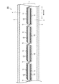
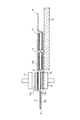
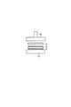
第1実施形態に係る太陽電池モジュール100の概略構成について、図1を参照しながら説明する。図1は、第1実施形態に係る太陽電池モジュール100の側面図である。1. First Embodiment (Configuration of Solar Cell Module)
A schematic configuration of the
太陽電池モジュール100は、太陽電池ストリング1、受光面側保護材2、裏面側保護材3及び封止材4を備える。
The
太陽電池ストリング1は、受光面側保護材2と裏面側保護材3との間に封止材4によって封止される。太陽電池ストリング1の詳細な構成については後述する。 The solar cell string 1 is sealed with a sealing material 4 between the light receiving surface side protective material 2 and the back surface side protective material 3. The detailed configuration of the solar cell string 1 will be described later.
受光面側保護材2は、太陽電池ストリング1の受光面側に配置され、太陽電池モジュール100の表面を保護する。受光面側保護材2としては、透光性及び遮水性を有するガラス、透光性プラスチック等を用いることができる。
The light receiving surface side protection member 2 is disposed on the light receiving surface side of the solar cell string 1 and protects the surface of the
裏面側保護材3は、太陽電池ストリング1の裏面側に配置され、太陽電池モジュール100の背面を保護する。裏面側保護材3としては、PET(Polyethylene Terephthalate)等の樹脂フィルム、Al箔を樹脂フィルムでサンドイッチした構造を有する積層フィルムなどを用いることができる。
The back surface side protective material 3 is disposed on the back surface side of the solar cell string 1 and protects the back surface of the
封止材4は、受光面側保護材2と裏面側保護材3との間で太陽電池ストリング1を封止する。封止材4としては、EVA、EEA、PVB、シリコン、ウレタン、アクリル、エポキシ等の透光性の樹脂を用いることができる。 The sealing material 4 seals the solar cell string 1 between the light receiving surface side protective material 2 and the back surface side protective material 3. As the sealing material 4, a translucent resin such as EVA, EEA, PVB, silicon, urethane, acrylic, or epoxy can be used.
なお、このような太陽電池モジュール100の外周には、Alフレーム(不図示)を取り付けることができる。
An Al frame (not shown) can be attached to the outer periphery of such a
(太陽電池ストリングの構成)
第1実施形態に係る太陽電池ストリング1の構成について、図1を参照しながら説明する。図1は、太陽電池ストリング1の側面図である。(Configuration of solar cell string)
The configuration of the solar cell string 1 according to the first embodiment will be described with reference to FIG. FIG. 1 is a side view of the solar cell string 1.
太陽電池ストリング1は、複数の太陽電池10と、配線材11と、樹脂接着剤12とを備える。太陽電池ストリング1は、配列方向に従って配列された複数の太陽電池10を配線材11によって互いに接続することにより構成されている。
The solar cell string 1 includes a plurality of
太陽電池10は、太陽光が入射する受光面と、受光面の反対側に設けられた裏面とを有する。太陽電池10の受光面と裏面とは、太陽電池10の主面である。太陽電池10の受光面上及び裏面上には集電電極が形成されている。太陽電池10の構成については後述する。
配線材11は、一の太陽電池10の受光面上に形成された集電電極と、一の太陽電池に隣接する他の太陽電池10の裏面上に形成された集電電極とに接合されている。これにより、一の太陽電池10と他の太陽電池10とが、電気的に接続されている。配線材11としては、薄板状或いは縒り線状に成形された銅等の導電材を用いることができる。なお、配線材11には、薄板状の銅等の表面に軟導電体(共晶半田など)がメッキされていてもよい。
The
樹脂接着剤12は、配線材11と太陽電池10との間に配設されている。即ち、配線材11は、樹脂接着剤12を介して太陽電池10に接合されている。樹脂接着剤12は、共晶半田の融点以下、即ち、約200℃以下の温度で硬化することが好ましい。樹脂接着剤12としては、例えば、アクリル樹脂、柔軟性の高いポリウレタン系などの熱硬化性樹脂接着剤の他、エポキシ樹脂、アクリル樹脂、あるいはウレタン樹脂に硬化剤を混合させた2液反応系接着剤などを用いることができる。
The
本実施形態に係る樹脂接着剤12としては、エポキシ樹脂を主成分とする帯状フィルム接着剤を用いる。樹脂接着剤12は、硬化剤を含ませることにより180℃で十数秒加熱することにより完全に硬化される。また、樹脂接着剤12には導電性粒子が含まれている。導電性粒子としては、ニッケル、金コート付きニッケル、或いはプラスチックに導電性金属(金など)をコートした粒子を用いることができる。
As the
(太陽電池の構成)
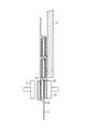
次に、太陽電池10の構成について、図2を参照しながら説明する。図2(a)は、本実施形態に係る太陽電池10の平面図である。図2(b)は、配線材11が樹脂接着剤12を介して太陽電池10に接合された状態を示す。(Configuration of solar cell)
Next, the configuration of the
太陽電池10は、図2(a)に示すように、光電変換部20、細線電極30及び接続用電極40を備えている。
As shown in FIG. 2A, the
光電変換部20は、受光面において太陽光を受けることにより光生成キャリアを生成する。光生成キャリアとは、太陽光が光電変換部20に吸収されることにより生成される正孔と電子とをいう。光電変換部20は、その内部にn型領域とp型領域とを有しており、n型領域とp型領域との界面で半導体接合が形成されている。光電変換部20は、単結晶Si、多結晶Si等の結晶系半導体材料や、GaAs、InP等の化合物半導体材料等の半導体材料などにより構成される半導体基板を用いて形成することができる。なお、光電変換部20は、単結晶シリコン基板と非晶質シリコン層との間に実質的に真性な非晶質シリコン層を挟み、その界面での欠陥を低減し、ヘテロ結合界面の特性を改善した構造、いわゆるHIT構造を有していてもよい。
The
細線電極30は、光電変換部20から光生成キャリアを集電する電極である。図2(a)に示すように、細線電極30は、配列方向に略直交する方向に沿ってライン状に形成されている。細線電極30は、光電変換部20上の略全域にわたって複数本形成されている。細線電極30は、樹脂材料をバインダーとし、銀粒子等の導電性粒子をフィラーとした樹脂型導電性ペーストを用いて形成することができる。
The
図1に示すように、細線電極30は、受光面及び裏面の両面上において同様に形成されている。なお、光電変換部20の裏面に形成される細線電極30は、光電変換部20の裏面全面を覆うように形成されていても良い。
As shown in FIG. 1, the
接続用電極40は、配線材11が接続される電極である。接続用電極40は、複数本の細線電極30から光生成キャリアを集電する。図2(a)に示すように、接続用電極40は、細線電極30と交差するように、配列方向に沿ってライン状に形成されている。接続用電極40は、樹脂材料をバインダーとし、銀粒子等の導電性粒子をフィラーとした樹脂型導電性ペーストを用いて形成することができる。
The
図1に示すように、接続用電極40は、受光面及び裏面の両面上において同様に形成されている。本実施形態に係る太陽電池10は、2本の接続用電極40を備える。光電変換部20の受光面上及び裏面上において、複数の細線電極30と接続用電極40とが格子状に形成されている。なお、接続用電極40の本数は、光電変換部20の大きさなどを考慮して、適当な本数に設定することができる。
As shown in FIG. 1, the
ここで、図2(b)に示すように、樹脂接着剤12は、接続用電極40上において、配列方向に沿って配置される。配線材11は、樹脂接着剤12上において、配列方向に沿って配置される。従って、光電変換部20上には、接続用電極40、樹脂接着剤12及び配線材11が順次積層されている。
Here, as shown in FIG. 2B, the
なお、本実施形態では、帯状の樹脂接着剤12の幅が、接続用電極40の幅よりも大きいが、樹脂接着剤12の幅は、接続用電極40の幅と略同等であってもよく、また、接続用電極40の幅より小さくてもよい。
In this embodiment, the width of the strip-shaped
(太陽電池ストリングの製造方法)
次に、本実施形態に係る太陽電池ストリングの製造方法について、図3乃至図6を用いて説明する。本実施形態において、太陽電池ストリング1は太陽電池10をn個備える。太陽電池10は受光面上及び裏面上それぞれに接続用電極40を2本ずつ有する。(Method for manufacturing solar cell string)
Next, a method for manufacturing a solar cell string according to this embodiment will be described with reference to FIGS. In the present embodiment, the solar cell string 1 includes n
(仮接着工程1)
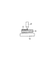
まず、n個の太陽電池10を収納カセット(不図示)内に重ねて収納する。次に、載置台53に一つの太陽電池10を移動する。太陽電池10の受光面上に形成された集電電極(細線電極30、接続用電極40)の形成パターンを確認し、太陽電池10の載置台53上における位置を微調整する。(Temporary bonding process 1)
First, n
次に、上述の樹脂接着剤12を、太陽電池10の受光面上に形成された接続用電極40上に貼付し、第1ツール56によって太陽電池10の受光面上に形成された接続用電極40に圧着する。この際、第1ツール56を加熱しておくことにより、樹脂接着剤12を接続用電極40に円滑に貼り付けることができる。以上により、太陽電池10の受光面上に形成された接続用電極40に樹脂接着剤12が貼付される。
Next, the above-mentioned
このような樹脂接着剤12の貼付は、2本の接続用電極40それぞれについて同時に行うことができる。
Such application of the
以上の工程をn個の太陽電池10それぞれについて繰返し行う。
The above process is repeated for each of the n
(仮接着工程2)
まず、太陽電池10の主面の配列方向における長さの約2倍の長さを有する配線材11を準備する。(Temporary bonding process 2)
First, the
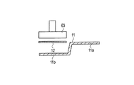
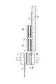
次に、図4に示すように、配線材11の中央付近に、配線材11の厚み方向に段を形成する。このような段を形成することにより、配線材11を、太陽電池10の受光面上に配置される第1部分11aと、太陽電池10の裏面上に配置される第2部分11bとに区別する。なお、段の高さは、太陽電池10の厚みによって適宜設定することができる。
Next, as shown in FIG. 4, a step is formed in the thickness direction of the
次に、第2部分11b上に、上述の樹脂接着剤12を第2ツール63を用いてを圧着する。この際、第2ツール63を加熱しておくことにより、樹脂接着剤12を第2部分11b上に円滑に圧着することができる。
Next, the above-mentioned
以上により、配線材11に樹脂接着剤12が貼付される。このような工程を2(n+1)回繰返して行う。
The
(仮接着工程3)
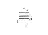
次に、一の太陽電池10の受光面上に形成された接続用電極40上に、樹脂接着剤12を挟んで一の配線材11の第1部分11aを配置するとともに、一の太陽電池10の裏面上に形成された接続用電極40を、樹脂接着剤12を挟んで他の配線材11の第2部分11b上に配置する(工程A)。(Temporary bonding process 3)
Next, the
具体的には、まず、図5に示す第3ツール70上に、2本の配線材11それぞれの第2部分11bを、樹脂接着剤12を上に向けて配置する。
Specifically, first, the
次に、太陽電池10を2本の配線材11それぞれの第2部分11b上に配置する。
Next, the
次に、太陽電池10の受光面上に形成された2本の接続用電極40上に、2本の配線材11それぞれの第1部分11aを配置する。これにより、配線材11、樹脂接着剤12、太陽電池10、樹脂接着剤12及び配線材11が順次積層された積層体が第3ツール70上に形成される。
Next, the
次に、第4ツール71を用いて、上記積層体の上方から積層体を1〜2MPaで1〜3秒間加圧する。この際、第4ツール71を約70〜110℃に加熱しておくことにより、樹脂接着剤12を軟化温度(約50〜90℃)以上かつ硬化温度より低い温度で加熱する(工程B)。これにより、太陽電池10の受光面上及び裏面上それぞれに2本の配線材11が仮接着される。
Next, using the
配線材11が仮接着された太陽電池10を載置台72上に移動させながら、上記工程をn回繰り返し行う(工程C)。これにより、n個の太陽電池10と2(n+1)本の配線材11とを備える仮接着状態の太陽電池ストリング1が形成される。
The above process is repeated n times while moving the
(本圧着工程)
次に、仮接着状態の太陽電池ストリング1を本圧着ステージに移動して、太陽電池10と配線材11との本圧着を行う。本実施形態において、「本圧着」とは、樹脂接着剤12を完全に硬化させることにより、太陽電池10と配線材11とを接合することをいう。(Main crimping process)
Next, the solar cell string 1 in the temporarily bonded state is moved to the final pressure bonding stage, and the final pressure bonding between the
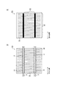
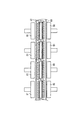
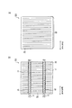
図6に示すように、本圧着ステージでは、上下一対の第5ツール80と第6ツール81とがn組並べられており、仮接着状態の太陽電池ストリング1をn組の第5ツール80と第6ツール81との間に配置する。第5ツール80と仮接着状態の太陽電池ストリング1との間、及び第6ツール81と仮接着状態の太陽電池ストリング1との間には、離型作用のあるテフロン(登録商標)製のシート82,83を配置する。
As shown in FIG. 6, in this crimping stage, n pairs of upper and lower pairs of
次に、n組の第5ツール80と第6ツール81とによって、仮接着状態の太陽電池ストリング1を、上下から2〜3MPaで15〜20秒間加圧する。即ち、配線材11を樹脂接着剤12に押し付ける。この際、n組の第5ツール80と第6ツール81とを約150〜210℃に加熱しておくことにより、樹脂接着剤12を硬化温度(約130〜180℃)以上の温度で加熱する(工程D)。これにより、樹脂接着剤12は完全に硬化され、配線材11が太陽電池10に接合される。
Next, the n sets of the
(太陽電池モジュールの製造方法)
次に、太陽電池ストリング1を備える太陽電池モジュール100の製造方法について説明する。(Method for manufacturing solar cell module)
Next, the manufacturing method of the
まず、ガラス基板(受光面側保護材2)上に、EVA(封止材4)シート、太陽電池ストリング1、EVA(封止材4)シート及びPETシート(裏面側保護材3)を順次積層して積層体とする。続いて、上記積層体を加熱圧着することにより、EVAを硬化させる。 First, an EVA (sealing material 4) sheet, a solar cell string 1, an EVA (sealing material 4) sheet, and a PET sheet (back side protection material 3) are sequentially laminated on a glass substrate (light-receiving surface side protection material 2). To obtain a laminate. Subsequently, EVA is cured by thermocompression bonding of the laminate.
このように製造される太陽電池モジュール100には、端子ボックスやAlフレーム等を取り付けることができる。
A terminal box, an Al frame, or the like can be attached to the
(作用及び効果)
本実施形態に係る太陽電池モジュールの製造方法によれば、n個の太陽電池10それぞれの受光面及び裏面に配線材11を仮接着した後に、n個の太陽電池10を一括して熱圧着することにより樹脂接着剤12を完全に硬化させる。(Function and effect)
According to the method for manufacturing a solar cell module according to the present embodiment, after the
従って、樹脂接着剤12を用いた配線材11の熱圧着を、n個の太陽電池10それぞれに対して繰返し行う場合と比較して、製造時間を短縮することができる。
Accordingly, the manufacturing time can be shortened as compared with the case where the thermocompression bonding of the
具体的には、仮接着工程3において、n個の太陽電池10それぞれに対する配線材11の仮接着を行っている。このため、本圧着工程では、n個の太陽電池10全てについて一括して樹脂接着剤12を硬化させることができる。その結果、短時間で太陽電池ストリング1を製造することができる。
Specifically, in the temporary bonding step 3, the
さらに、太陽電池10と配線材11とが一旦仮接着されているため、本圧着工程において、配線材11が接続用電極40からずれることを抑制することができる。その結果、本圧着工程において配線材11にかかる圧力が太陽電池10の特定の箇所に集中することを回避することができるため、太陽電池10の破損を回避することができる。
Furthermore, since the
また、本実施形態に係る太陽電池ストリング1の製造方法によれば、仮接着工程1において、樹脂接着剤12は太陽電池10の裏面上に配置される配線材11に貼付され、仮接着工程2において、樹脂接着剤12は太陽電池10の受光面に貼付される。
Moreover, according to the manufacturing method of the solar cell string 1 which concerns on this embodiment, in the temporary adhesion process 1, the
従って、上述の仮接着工程3において、配線材11が太陽電池10の受光面上及び裏面上それぞれに対して正確に仮接着されていることを容易に確認することができる。
Therefore, in the temporary bonding step 3 described above, it can be easily confirmed that the
2.第2実施形態
次に、本発明の第2実施形態について、図7及び図8を参照しながら説明する。上記第1実施形態と本実施形態との相違点は、配線材11にのみ樹脂接着剤12を貼付する点である。従って、上記仮接着工程1は行わず、上記仮接着工程2を一の配線材11に対して2回繰返して行う。2. Second Embodiment Next, a second embodiment of the present invention will be described with reference to FIGS. The difference between the first embodiment and the present embodiment is that the
まず、図7に示すように、上記仮接着工程2を経た配線材11を裏返して配置する。
First, as shown in FIG. 7, the
次に、配線材11の第1部分11aに対して、第2ツール63を用いて樹脂接着剤12を圧着する。この際、第2ツール63を加熱しておくことにより、樹脂接着剤12を配線材11上に円滑に貼り付けることができる。
Next, the
以上により、配線材11の第1部分11a及び第2部分11bの両方に対して樹脂接着剤12が貼付される。このような工程を2(n+1)回繰返し行う。
As described above, the
次に、図8に示すように、太陽電池10の受光面上及び裏面上に配線材11を配置する。太陽電池10の受光面上及び裏面上には樹脂接着剤12が貼付されておらず、配線材11に樹脂接着剤12が貼付されている点以外は、上記仮接着工程3と同様である。
Next, as shown in FIG. 8, the
その後、上記本圧着工程を行って、太陽電池ストリング1を作製する。 Then, the said main compression bonding process is performed and the solar cell string 1 is produced.
本実施形態に係る太陽電池ストリングの製造方法によれば、太陽電池10に樹脂接着剤12を圧着する必要がない。
According to the method for manufacturing a solar cell string according to the present embodiment, it is not necessary to press-bond the
その結果、太陽電池10に樹脂接着剤12を接着する際に、太陽電池10が破損することを抑制することができる。また、このような太陽電池10の破損は、太陽電池を薄型化するほど顕著に発生するため、本実施形態に係る太陽電池ストリング1の製造方法によれば、薄型化された太陽電池に対しても歩留まりを低下させることなく太陽電池ストリングを製造することができる。
As a result, the
3.第3実施形態
次に、本発明の第3実施形態について、図9及び図10を参照しながら説明する。上記第1実施形態と本実施形態との相違点は、太陽電池10の受光面上及び裏面上に形成された接続用電極40に樹脂接着剤12を仮接着する点である。従って、上記仮接着工程2を行わず、上記仮接着工程1を太陽電池10の裏面についても行う。3. Third Embodiment Next, a third embodiment of the present invention will be described with reference to FIGS. The difference between the first embodiment and the present embodiment is that the
まず、上記仮接着工程1を経た太陽電池10を裏返して、裏面を上にして載置台53に配置する。
First, the
次に、太陽電池10の受光面上に形成された集電電極(細線電極30、接続用電極40)の形成パターンを確認し、載置台53上における太陽電池10の位置を微調整する。
Next, the formation pattern of the current collecting electrodes (
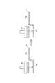
次に、図9に示すように、樹脂接着剤12を、太陽電池10の裏面上に形成された接続用電極上に配置し、第1ツール56によって接続用電極40に圧着する。この際、第1ツール56を加熱しておくことにより、樹脂接着剤12を接続用電極40に円滑に貼り付けることができる。このような樹脂接着剤12の貼付は、2本の接続用電極40それぞれに対して同時に行うことができる。
Next, as shown in FIG. 9, the
以上の工程をn個の太陽電池10それぞれについて繰返し行う。
The above process is repeated for each of the n
次に、図10に示すように、太陽電池10の受光面及び裏面に配線材11を仮接着する。太陽電池10の受光面及び裏面の両面に樹脂接着剤12が貼付されており、配線材11に樹脂接着剤12が貼付されていない点以外は、上記仮接着工程3と同様である。
Next, as shown in FIG. 10, the
その後、上記本圧着工程を行って、太陽電池ストリング1を作製する。 Then, the said main compression bonding process is performed and the solar cell string 1 is produced.
4.第4実施形態
次に、本発明の第4実施形態について、図11を参照しながら説明する。図11(a)は、本実施形態に係る太陽電池15の平面図である。図11(b)は、配線材11が樹脂接着剤16を介して太陽電池10に接合された状態を示す。4). Fourth Embodiment Next, a fourth embodiment of the present invention will be described with reference to FIG. FIG. 11A is a plan view of the
図11(a)に示すように、上記第1実施形態に係る太陽電池10と、本実施形態に係る太陽電池15との相違点は、受光面上及び裏面上に接続用電極40が形成されていない点である。また、上記第1実施形態に係る樹脂接着剤12と、本実施形態に係る樹脂接着剤16との相違点は、樹脂接着剤16が導電性粒子を含んでいない点である。当該相違点以外は、上記第1実施形態と同様である。
As shown in FIG. 11A, the difference between the
本実施形態に係る太陽電池ストリングの製造方法によれば、受光面上及び裏面上に接続用電極40が形成されていないため、仮接着工程1において太陽電池15を配置する位置の微調整を行う必要がなく、また、仮接着工程3において配線材11を配置する位置の微調整を行う必要がない。
According to the method for manufacturing a solar cell string according to the present embodiment, since the
また、太陽電池15は接続用電極40を備えていないため、細線電極30の一部は、本圧着工程において配線材11中に埋め込まれる。従って、細線電極30と配線材11との導通を直接確保することができるため、樹脂接着剤16に導電性粒子を含ませる必要がない。
Further, since the
5.第5実施形態
次に、本発明の第5実施形態について、図面を参照しながら説明する。以下においては、上述した第1実施形態と第5実施形態との相違点について主として説明する。5. Fifth Embodiment Next, a fifth embodiment of the present invention will be described with reference to the drawings. In the following, differences between the above-described first embodiment and the fifth embodiment will be mainly described.
具体的には、第5実施形態では、各配線材11は、各太陽電池10の受光面どうし、又は、各太陽電池10の裏面どうしに接続される。従って、各配線材11は、直線状に形成されており、各太陽電池10どうしの間隙において折り曲げられない。
Specifically, in the fifth embodiment, the
(太陽電池ストリングの構成)
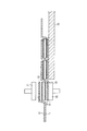
図12は、第5実施形態に係る太陽電池ストリングの側面図である。図12に示すように、太陽電池10aの受光面と太陽電池10bの受光面とは、配線材11cによって接続される。また、太陽電池10aの裏面と太陽電池10bの裏面とは、配線材11dによって接続される。第5実施形態では、太陽電池10aの受光面の極性と太陽電池10bの受光面の極性とが異なっており、太陽電池10aと太陽電池10bとは、配線材11c及び配線材11dによって電気的に直列に接続される。(Configuration of solar cell string)
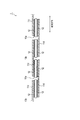
FIG. 12 is a side view of the solar cell string according to the fifth embodiment. As shown in FIG. 12, the light receiving surface of the
(太陽電池ストリングの製造方法)
次に、第5実施形態に係る太陽電池ストリングの製造方法について、図13及び図14を用いて説明する。なお、上記第1実施形態と第5実施形態とは、上記仮接着工程2及び仮接着工程3において相違する。(Method for manufacturing solar cell string)
Next, the manufacturing method of the solar cell string which concerns on 5th Embodiment is demonstrated using FIG.13 and FIG.14. The first embodiment and the fifth embodiment are different in the temporary bonding step 2 and the temporary bonding step 3.
(仮接着工程1)
まず、太陽電池10の受光面上に形成された接続用電極40上に樹脂接着剤12を配置し、第1ツール56によって接続用電極40に圧着する(図3参照)。このような仮接着工程1を太陽電池10a及び太陽電池10bそれぞれについて行う。(Temporary bonding process 1)
First, the
(仮接着工程2)
次に、図13に示すように、太陽電池10aの裏面と太陽電池10bの裏面とに接続される配線材11dに、第2ツール63を用いて樹脂接着剤12を圧着する。具体的には、樹脂接着剤12を、配線材11dのうち、太陽電池10a及び太陽電池10bそれぞれの裏面に形成された接続用電極40に接続される部分に貼付する。(Temporary bonding process 2)
Next, as shown in FIG. 13, the
(仮接着工程3)
次に、太陽電池10a及び太陽電池10bそれぞれを配線材11d上に配置するとともに、配線材11cを太陽電池10a上及び太陽電池10b上に配置する(工程A)。(Temporary bonding process 3)
Next, the
具体的には、図14に示すように、第3ツール70上に、配線材11d、太陽電池10a又は太陽電池10b、配線材11cを順次配置する。
Specifically, as shown in FIG. 14, the
次に、第4ツール71を用いて、配線材11cの上方から1〜2MPaで1〜3秒間加圧する。この際、第4ツール71を約70〜110℃に加熱しておくことにより、樹脂接着剤12を軟化温度(約50〜90℃)以上かつ硬化温度より低い温度で加熱する(工程B)。
Next, using the
配線材11c及び配線材11dが仮接着された太陽電池10a又は太陽電池10bを載置台72上に移動させながら、上記工程を繰り返し行う(工程C)。これにより、仮接着状態の太陽電池ストリングが形成される。
While moving the
(本圧着工程)
次に、仮接着状態の太陽電池ストリングを本圧着ステージに移動して、仮接着状態の太陽電池ストリングを、上下から2〜3MPaで15〜20秒間加圧する(工程D)。これにより、樹脂接着剤12は硬化される。(Main crimping process)
Next, the temporarily adhered solar cell string is moved to the main pressure bonding stage, and the temporarily adhered solar cell string is pressurized from 2 to 3 MPa from the top and bottom for 15 to 20 seconds (step D). Thereby, the
(その他の実施形態)
本発明は上記の実施形態によって記載したが、この開示の一部をなす論述及び図面はこの発明を限定するものであると理解すべきではない。この開示から当業者には様々な代替実施形態、実施例及び運用技術が明らかとなろう。(Other embodiments)
Although the present invention has been described according to the above-described embodiments, it should not be understood that the descriptions and drawings constituting a part of this disclosure limit the present invention. From this disclosure, various alternative embodiments, examples and operational techniques will be apparent to those skilled in the art.
例えば、上記実施形態では、太陽電池の受光面上及び裏面上に、配列方向に略直交する方向に沿って細線電極30を形成したが、配列方向に対して傾きを有する方向にそって形成してもよい。
For example, in the above embodiment, the
また、上記実施形態では、樹脂接着剤12として、帯状フィルム接着剤を用いたが、図15に示すように、液体状の樹脂接着剤12をディスペンサー57によって塗布してもよい。
Moreover, in the said embodiment, although the strip | belt-shaped film adhesive was used as the
また、上記実施形態では第5ツール80と第6ツール81とをn組配置したが、第5ツール80と第6ツール81との組数は、設備投資費を考慮して任意に設定することができる。
In the above embodiment, n sets of the
このように、本発明はここでは記載していない様々な実施形態等を含むことは勿論である。従って、本発明の技術的範囲は上記の説明から妥当な特許請求の範囲に係る発明特定事項によってのみ定められるものである。 As described above, the present invention naturally includes various embodiments not described herein. Therefore, the technical scope of the present invention is defined only by the invention specifying matters according to the scope of claims reasonable from the above description.
なお、日本国特許出願第2007-184962号(2007年7月13日出願)の全内容が、参照により、本願明細書に組み込まれている。 Note that the entire content of Japanese Patent Application No. 2007-184962 (filed on July 13, 2007) is incorporated herein by reference.
以上のように、本発明によると、製造時間の短縮を可能とする太陽電池ストリングの製造方法を提供することができるため、太陽光発電分野において有用である。 As described above, according to the present invention, it is possible to provide a method for manufacturing a solar cell string that enables a reduction in manufacturing time, which is useful in the field of photovoltaic power generation.
Claims (7)
前記複数の太陽電池に含まれる一の太陽電池の前記受光面上に、前記一の太陽電池の一方に隣接する太陽電池の前記裏面上に接続すべき前記配線材を、熱硬化性の樹脂接着剤を挟んで配置するとともに、前記一の太陽電池の前記裏面上に、前記一の太陽電池の他方に隣接する太陽電池の前記受光面上に接続すべき前記配線材を、前記樹脂接着剤を挟んで配置する工程Aと、
前記樹脂接着剤を、前記樹脂接着剤の軟化温度より高く、かつ、前記樹脂接着剤の硬化温度より低い温度で加熱することにより、前記配線材を前記一の太陽電池に接着する工程Bと、
前記工程Aと前記工程Bとを交互に複数回繰り返し行うことにより、前記複数の太陽電池の全てに前記配線材を接着する工程Cと、
前記工程Cの後に前記配線材を前記樹脂接着剤に押し付けながら、前記樹脂接着剤を前記樹脂接着剤の硬化温度以上の温度で加熱することにより前記樹脂接着剤を硬化させる工程Dと
を備えることを特徴とする太陽電池ストリングの製造方法。 Manufacture of a solar cell string comprising a plurality of solar cells having a light receiving surface on which light is incident and a back surface provided on the opposite side of the light receiving surface, and a wiring member electrically connecting each of the plurality of solar cells A method,
The wiring material to be connected to the back surface of the solar cell adjacent to one of the solar cells on the light receiving surface of the solar cell included in the plurality of solar cells, and thermosetting resin adhesion The wiring material to be connected to the light receiving surface of the solar cell adjacent to the other side of the one solar cell on the back surface of the one solar cell, and the resin adhesive Step A that is sandwiched and disposed,
Step B for bonding the wiring material to the one solar cell by heating the resin adhesive at a temperature higher than the softening temperature of the resin adhesive and lower than the curing temperature of the resin adhesive;
Step C for adhering the wiring material to all of the plurality of solar cells by repeatedly performing the step A and the step B a plurality of times alternately;
And the step D of curing the resin adhesive by heating the resin adhesive at a temperature equal to or higher than the curing temperature of the resin adhesive while pressing the wiring member against the resin adhesive after the step C. The manufacturing method of the solar cell string characterized by these.
前記樹脂接着剤は、前記配線材のうち前記一の太陽電池の前記裏面上に配置される部分と、前記一の太陽電池の前記受光面とに貼付されている
ことを特徴とする請求項1に記載の太陽電池ストリングの製造方法。 In step A,
The said resin adhesive is affixed on the part arrange | positioned on the said back surface of the said one solar cell among the said wiring materials, and the said light-receiving surface of the said one solar cell. The manufacturing method of the solar cell string as described in any one of.
前記樹脂接着剤は、前記配線材のうち前記一の太陽電池の前記裏面上に配置される部分と、前記配線材のうち前記一の太陽電池の前記受光面上に配置される部分とに貼付されている
ことを特徴とする請求項1に記載の太陽電池ストリングの製造方法。 In step A,
The resin adhesive is affixed to a portion of the wiring member disposed on the back surface of the one solar cell and a portion of the wiring member disposed on the light receiving surface of the one solar cell. The solar cell string manufacturing method according to claim 1, wherein the solar cell string is manufactured.
前記樹脂接着剤は、前記一の太陽電池の前記裏面と、前記配線材のうち前記一の太陽電池の前記受光面上に配置される部分とに貼付されている
ことを特徴とする請求項1に記載の太陽電池ストリングの製造方法。 In step A,
The said resin adhesive is affixed on the said back surface of the said one solar cell, and the part arrange | positioned on the said light-receiving surface of the said one solar cell among the said wiring materials. The manufacturing method of the solar cell string as described in any one of.
前記工程Dにおいて、
前記配線材を前記樹脂接着剤に押し付けることにより、前記細線電極の一部を前記配線材中に埋め込む
ことを特徴とする請求項1に記載の太陽電池ストリングの製造方法。 On the light receiving surface and the back surface of each of the plurality of solar cells, a plurality of fine wire electrodes are formed,
In step D,
The method for manufacturing a solar cell string according to claim 1, wherein a part of the thin wire electrode is embedded in the wiring material by pressing the wiring material against the resin adhesive.
前記複数の太陽電池を一括して熱圧着することにより前記樹脂接着剤を硬化させることを特徴とする請求項1に記載の太陽電池ストリングの製造方法。 In step D,
The method for producing a solar cell string according to claim 1, wherein the resin adhesive is cured by collectively thermocompression bonding the plurality of solar cells.
前記複数の太陽電池上に離型作用シートを配置して熱圧着することにより前記樹脂接着剤を硬化させることを特徴とする請求項1に記載の太陽電池ストリングの製造方法。 In step D,
The method for producing a solar cell string according to claim 1, wherein the resin adhesive is cured by disposing a release action sheet on the plurality of solar cells and thermocompression bonding.
Priority Applications (1)
| Application Number | Priority Date | Filing Date | Title |
|---|---|---|---|
| JP2009523585A JP5367569B2 (en) | 2007-07-13 | 2008-06-25 | Manufacturing method of solar cell module |
Applications Claiming Priority (4)
| Application Number | Priority Date | Filing Date | Title |
|---|---|---|---|
| JP2007184962 | 2007-07-13 | ||
| JP2007184962 | 2007-07-13 | ||
| PCT/JP2008/061539 WO2009011209A1 (en) | 2007-07-13 | 2008-06-25 | Solar cell module manufacturing method |
| JP2009523585A JP5367569B2 (en) | 2007-07-13 | 2008-06-25 | Manufacturing method of solar cell module |
Related Child Applications (1)
| Application Number | Title | Priority Date | Filing Date |
|---|---|---|---|
| JP2013021383A Division JP2013080982A (en) | 2007-07-13 | 2013-02-06 | Method and apparatus for manufacturing solar cell module |
Publications (2)
| Publication Number | Publication Date |
|---|---|
| JPWO2009011209A1 JPWO2009011209A1 (en) | 2010-09-16 |
| JP5367569B2 true JP5367569B2 (en) | 2013-12-11 |
Family
ID=40259548
Family Applications (2)
| Application Number | Title | Priority Date | Filing Date |
|---|---|---|---|
| JP2009523585A Active JP5367569B2 (en) | 2007-07-13 | 2008-06-25 | Manufacturing method of solar cell module |
| JP2013021383A Pending JP2013080982A (en) | 2007-07-13 | 2013-02-06 | Method and apparatus for manufacturing solar cell module |
Family Applications After (1)
| Application Number | Title | Priority Date | Filing Date |
|---|---|---|---|
| JP2013021383A Pending JP2013080982A (en) | 2007-07-13 | 2013-02-06 | Method and apparatus for manufacturing solar cell module |
Country Status (7)
| Country | Link |
|---|---|
| US (1) | US8298363B2 (en) |
| EP (1) | EP2169725B1 (en) |
| JP (2) | JP5367569B2 (en) |
| KR (1) | KR101476478B1 (en) |
| CN (1) | CN101689576B (en) |
| TW (1) | TWI438916B (en) |
| WO (1) | WO2009011209A1 (en) |
Families Citing this family (49)
| Publication number | Priority date | Publication date | Assignee | Title |
|---|---|---|---|---|
| US20090289097A1 (en) * | 2008-05-21 | 2009-11-26 | Weng-Jin Wu | Wafer Leveling-Bonding System Using Disposable Foils |
| JP5377019B2 (en) * | 2009-03-23 | 2013-12-25 | 三洋電機株式会社 | Manufacturing method of solar cell module |
| JP5436901B2 (en) * | 2009-03-23 | 2014-03-05 | 三洋電機株式会社 | Manufacturing method of solar cell module |
| EP2439782A4 (en) | 2009-06-03 | 2013-07-31 | Shibaura Mechatronics Corp | Lead wire connection apparatus and connection method for semiconductor cells |
| JP5436055B2 (en) * | 2009-06-05 | 2014-03-05 | 芝浦メカトロニクス株式会社 | Lead wire connecting device and connecting method |
| JP5375414B2 (en) * | 2009-07-31 | 2013-12-25 | 信越化学工業株式会社 | Solar cell and manufacturing method thereof |
| JP5053347B2 (en) * | 2009-10-06 | 2012-10-17 | 芝浦メカトロニクス株式会社 | Semiconductor cell, solar cell module, lead wire connecting device and connecting method |
| KR101420547B1 (en) * | 2009-10-15 | 2014-07-17 | 히타치가세이가부시끼가이샤 | Conductive adhesive, solar cell, method for manufacturing solar cell, and solar cell module |
| JP5586273B2 (en) * | 2010-03-08 | 2014-09-10 | 富士機械製造株式会社 | Method and apparatus for manufacturing solar cell module |
| JP5318815B2 (en) * | 2010-04-19 | 2013-10-16 | デクセリアルズ株式会社 | Solar cell module and method for manufacturing solar cell module |
| JP2012015194A (en) * | 2010-06-29 | 2012-01-19 | Npc Inc | Manufacturing apparatus and method for solar battery string and apparatus and method for attaching adhesive agent |
| JP5021080B2 (en) * | 2011-01-20 | 2012-09-05 | 株式会社エヌ・ピー・シー | Solar cell string manufacturing apparatus and manufacturing method, wiring material crimping apparatus, and wiring material crimping method |
| JP5631661B2 (en) | 2010-08-27 | 2014-11-26 | 三洋電機株式会社 | Manufacturing method of solar cell module |
| KR101147232B1 (en) * | 2010-08-30 | 2012-05-18 | 삼성에스디아이 주식회사 | sealing material for solar cell and solar cell comprising thereof |
| US8561878B2 (en) * | 2010-09-27 | 2013-10-22 | Banyan Energy, Inc. | Linear cell stringing |
| JP5356347B2 (en) * | 2010-09-29 | 2013-12-04 | デクセリアルズ株式会社 | Solar cell module and method for manufacturing solar cell module |
| US8196798B2 (en) * | 2010-10-08 | 2012-06-12 | Kulicke And Soffa Industries, Inc. | Solar substrate ribbon bonding system |
| EP2634818B1 (en) * | 2010-10-26 | 2017-02-08 | Panasonic Intellectual Property Management Co., Ltd. | Method for producing solar cell module |
| US9324895B2 (en) | 2010-12-21 | 2016-04-26 | Mitsubishi Electric Corporation | Solar cell module and manufacturing method thereof |
| JP2012142427A (en) * | 2010-12-28 | 2012-07-26 | Npc Inc | Solar cell string manufacturing apparatus |
| CN102683441A (en) * | 2011-03-10 | 2012-09-19 | 阿特斯(中国)投资有限公司 | Solar cell module |
| JP5909667B2 (en) * | 2011-06-30 | 2016-04-27 | パナソニックIpマネジメント株式会社 | Solar cell module and manufacturing method thereof |
| JP2013026611A (en) * | 2011-07-26 | 2013-02-04 | Sanyo Electric Co Ltd | Manufacturing method of solar cell module |
| JP5995007B2 (en) * | 2011-08-31 | 2016-09-21 | パナソニックIpマネジメント株式会社 | Solar cell module |
| JP6037176B2 (en) * | 2011-08-31 | 2016-11-30 | パナソニックIpマネジメント株式会社 | Manufacturing method of solar cell module |
| CN102270707B (en) * | 2011-09-02 | 2014-11-05 | 江西赛维Ldk太阳能高科技有限公司 | Connection method of solar cells |
| CN102509747A (en) * | 2011-11-08 | 2012-06-20 | 江西赛维Ldk太阳能高科技有限公司 | Connecting method for solar cells and bus-bar with conductive adhesives |
| WO2013069425A1 (en) | 2011-11-09 | 2013-05-16 | 三菱電機株式会社 | Solar cell module and manufacturing method therefor |
| CN102544224B (en) * | 2012-01-19 | 2015-04-29 | 浙江师范大学 | Adhesive technology for solar battery module |
| JP5611250B2 (en) * | 2012-01-25 | 2014-10-22 | 三菱電機株式会社 | Method for manufacturing photovoltaic module |
| EP2811532A4 (en) * | 2012-01-31 | 2015-07-01 | Sanyo Electric Co | Solar cell module, and method for manufacturing solar cell module |
| JP5242824B1 (en) * | 2012-02-29 | 2013-07-24 | 株式会社エヌ・ピー・シー | Conductive paste coating mechanism and cell wiring device |
| WO2013132655A1 (en) * | 2012-03-09 | 2013-09-12 | 三洋電機株式会社 | Method for manufacturing solar cell module, and solar cell module |
| WO2013140616A1 (en) * | 2012-03-23 | 2013-09-26 | 三洋電機株式会社 | Solar cell module manufacturing method and solar cell module manufacturing apparatus |
| JP6037245B2 (en) * | 2012-06-28 | 2016-12-07 | パナソニックIpマネジメント株式会社 | Solar cell module manufacturing method and solar cell module manufacturing apparatus |
| US8748212B2 (en) * | 2012-08-31 | 2014-06-10 | Komax Holding Ag | Method and device for producing solar cell strings |
| DE112014000655T5 (en) * | 2013-02-01 | 2015-10-08 | Panasonic Intellectual Property Management Co., Ltd. | A solar cell module manufacturing method and a solar cell module manufacturing apparatus |
| DE102013103837A1 (en) * | 2013-04-16 | 2014-10-16 | Teamtechnik Maschinen Und Anlagen Gmbh | Application of conductive adhesive on solar cells |
| JP2013243415A (en) * | 2013-09-12 | 2013-12-05 | Sanyo Electric Co Ltd | Method of manufacturing solar cell module |
| KR102175893B1 (en) | 2014-02-24 | 2020-11-06 | 엘지전자 주식회사 | Manufacturing method of solar cell module |
| KR101757879B1 (en) * | 2014-08-04 | 2017-07-26 | 엘지전자 주식회사 | Solar cell module |
| US9899546B2 (en) | 2014-12-05 | 2018-02-20 | Tesla, Inc. | Photovoltaic cells with electrodes adapted to house conductive paste |
| US10236406B2 (en) | 2014-12-05 | 2019-03-19 | Solarcity Corporation | Systems and methods for targeted annealing of photovoltaic structures |
| KR102231903B1 (en) * | 2015-06-03 | 2021-03-25 | 엘지전자 주식회사 | Joining apparatus for solar cell and ribbon |
| KR101661859B1 (en) | 2015-09-09 | 2016-09-30 | 엘지전자 주식회사 | Solar cell module and manufacturing method thereof |
| KR101751946B1 (en) * | 2015-12-28 | 2017-06-28 | 엘지전자 주식회사 | Solar cell module |
| CN109877488B (en) * | 2019-01-31 | 2021-11-12 | 泰州隆基乐叶光伏科技有限公司 | Welding method and hot melt adhesive |
| KR102219056B1 (en) * | 2019-02-13 | 2021-02-23 | ㈜에이치엔에스 | Method for adhering ribbon to overlapped solar cell module |
| JP7403343B2 (en) * | 2020-02-18 | 2023-12-22 | パナソニックホールディングス株式会社 | Method for manufacturing solar cell modules |
Citations (10)
| Publication number | Priority date | Publication date | Assignee | Title |
|---|---|---|---|---|
| JPH01212480A (en) * | 1988-02-19 | 1989-08-25 | Sanyo Electric Co Ltd | Modularization of solar battery |
| JPH036867A (en) * | 1989-06-05 | 1991-01-14 | Mitsubishi Electric Corp | Electrode structure of photovoltaic device, forming method, and apparatus for manufacture thereof |
| JPH0846226A (en) * | 1994-07-29 | 1996-02-16 | Canon Inc | Electrode for photovoltaic element, and photovoltaic element |
| JP2001357897A (en) * | 2000-06-14 | 2001-12-26 | Fuji Xerox Co Ltd | Photoelectric conversion module |
| JP2003086822A (en) * | 2001-09-10 | 2003-03-20 | Aisin Seiki Co Ltd | Solar battery module and method for manufacturing the same |
| JP2003133570A (en) * | 2001-10-24 | 2003-05-09 | Fuji Electric Corp Res & Dev Ltd | Method of manufacturing solar battery module |
| JP2004247402A (en) * | 2003-02-12 | 2004-09-02 | Sanyo Electric Co Ltd | Solar cell module and its manufacturing method |
| JP2005101519A (en) * | 2003-09-05 | 2005-04-14 | Hitachi Chem Co Ltd | Solar cell unit and solar cell module |
| JP2005243935A (en) * | 2004-02-26 | 2005-09-08 | Shin Etsu Handotai Co Ltd | Solar cell module and manufacturing method thereof |
| JP2007158302A (en) * | 2005-11-10 | 2007-06-21 | Hitachi Chem Co Ltd | Connection structure and method of manufacturing same |
Family Cites Families (8)
| Publication number | Priority date | Publication date | Assignee | Title |
|---|---|---|---|---|
| AU695669B2 (en) * | 1994-05-19 | 1998-08-20 | Canon Kabushiki Kaisha | Photovoltaic element, electrode structure thereof, and process for producing the same |
| JP2750085B2 (en) * | 1994-06-07 | 1998-05-13 | キヤノン株式会社 | Method for producing current collecting electrode of photovoltaic element |
| JPH08330615A (en) * | 1995-05-30 | 1996-12-13 | Canon Inc | Series solar cell and manufacture thereof |
| JP4046819B2 (en) * | 1997-11-12 | 2008-02-13 | キヤノン株式会社 | Photovoltaic element manufacturing method |
| JP4240587B2 (en) | 1998-07-03 | 2009-03-18 | 株式会社エヌ・ピー・シー | Tab lead soldering equipment |
| JP4738149B2 (en) * | 2005-02-22 | 2011-08-03 | 京セラ株式会社 | Solar cell module |
| JP3123842U (en) * | 2006-05-18 | 2006-07-27 | 京セラケミカル株式会社 | Solar cell module |
| JP5436901B2 (en) * | 2009-03-23 | 2014-03-05 | 三洋電機株式会社 | Manufacturing method of solar cell module |
-
2008
- 2008-06-23 TW TW097123307A patent/TWI438916B/en active
- 2008-06-25 JP JP2009523585A patent/JP5367569B2/en active Active
- 2008-06-25 US US12/668,608 patent/US8298363B2/en active Active
- 2008-06-25 WO PCT/JP2008/061539 patent/WO2009011209A1/en active Application Filing
- 2008-06-25 CN CN2008800236657A patent/CN101689576B/en active Active
- 2008-06-25 KR KR1020107000694A patent/KR101476478B1/en active IP Right Grant
- 2008-06-25 EP EP08790606.1A patent/EP2169725B1/en active Active
-
2013
- 2013-02-06 JP JP2013021383A patent/JP2013080982A/en active Pending
Patent Citations (10)
| Publication number | Priority date | Publication date | Assignee | Title |
|---|---|---|---|---|
| JPH01212480A (en) * | 1988-02-19 | 1989-08-25 | Sanyo Electric Co Ltd | Modularization of solar battery |
| JPH036867A (en) * | 1989-06-05 | 1991-01-14 | Mitsubishi Electric Corp | Electrode structure of photovoltaic device, forming method, and apparatus for manufacture thereof |
| JPH0846226A (en) * | 1994-07-29 | 1996-02-16 | Canon Inc | Electrode for photovoltaic element, and photovoltaic element |
| JP2001357897A (en) * | 2000-06-14 | 2001-12-26 | Fuji Xerox Co Ltd | Photoelectric conversion module |
| JP2003086822A (en) * | 2001-09-10 | 2003-03-20 | Aisin Seiki Co Ltd | Solar battery module and method for manufacturing the same |
| JP2003133570A (en) * | 2001-10-24 | 2003-05-09 | Fuji Electric Corp Res & Dev Ltd | Method of manufacturing solar battery module |
| JP2004247402A (en) * | 2003-02-12 | 2004-09-02 | Sanyo Electric Co Ltd | Solar cell module and its manufacturing method |
| JP2005101519A (en) * | 2003-09-05 | 2005-04-14 | Hitachi Chem Co Ltd | Solar cell unit and solar cell module |
| JP2005243935A (en) * | 2004-02-26 | 2005-09-08 | Shin Etsu Handotai Co Ltd | Solar cell module and manufacturing method thereof |
| JP2007158302A (en) * | 2005-11-10 | 2007-06-21 | Hitachi Chem Co Ltd | Connection structure and method of manufacturing same |
Also Published As
| Publication number | Publication date |
|---|---|
| US8298363B2 (en) | 2012-10-30 |
| KR20100036315A (en) | 2010-04-07 |
| EP2169725B1 (en) | 2014-05-07 |
| JP2013080982A (en) | 2013-05-02 |
| CN101689576B (en) | 2013-01-16 |
| KR101476478B1 (en) | 2014-12-26 |
| EP2169725A1 (en) | 2010-03-31 |
| WO2009011209A1 (en) | 2009-01-22 |
| TWI438916B (en) | 2014-05-21 |
| CN101689576A (en) | 2010-03-31 |
| TW200905902A (en) | 2009-02-01 |
| US20100181011A1 (en) | 2010-07-22 |
| JPWO2009011209A1 (en) | 2010-09-16 |
| EP2169725A4 (en) | 2013-01-16 |
Similar Documents
| Publication | Publication Date | Title |
|---|---|---|
| JP5367569B2 (en) | Manufacturing method of solar cell module | |
| JP4294048B2 (en) | Solar cell module | |
| JP5484663B2 (en) | Manufacturing method of solar cell module | |
| JP5367587B2 (en) | Solar cell module and solar cell | |
| JP5556827B2 (en) | Manufacturing method of solar cell module | |
| JP5861044B2 (en) | Solar cell module | |
| JP6064177B2 (en) | Manufacturing method of solar cell module | |
| JP5046743B2 (en) | Solar cell module and manufacturing method thereof | |
| EP2075852A2 (en) | Solar cell module and method of manufacturing the same | |
| WO2009104627A1 (en) | Solar cell module | |
| JP5100206B2 (en) | Solar cell module | |
| JP5178489B2 (en) | Solar cell module and manufacturing method thereof | |
| JP5377409B2 (en) | Solar cell module and manufacturing method thereof | |
| JP5306353B2 (en) | Solar cell module | |
| JP2011222744A (en) | Tab wire for connecting solar battery, connection method and solar battery module | |
| JP2014175520A (en) | Solar battery module and manufacturing method for the same | |
| JP5490466B2 (en) | Solar cell module | |
| WO2017056363A1 (en) | Method for producing solar cell module |
Legal Events
| Date | Code | Title | Description |
|---|---|---|---|
| A621 | Written request for application examination |
Free format text: JAPANESE INTERMEDIATE CODE: A621 Effective date: 20110531 |
|
| A131 | Notification of reasons for refusal |
Free format text: JAPANESE INTERMEDIATE CODE: A131 Effective date: 20120821 |
|
| A521 | Request for written amendment filed |
Free format text: JAPANESE INTERMEDIATE CODE: A523 Effective date: 20121004 |
|
| A521 | Request for written amendment filed |
Free format text: JAPANESE INTERMEDIATE CODE: A523 Effective date: 20121004 |
|
| A131 | Notification of reasons for refusal |
Free format text: JAPANESE INTERMEDIATE CODE: A131 Effective date: 20121211 |
|
| A521 | Request for written amendment filed |
Free format text: JAPANESE INTERMEDIATE CODE: A523 Effective date: 20130201 |
|
| TRDD | Decision of grant or rejection written | ||
| A01 | Written decision to grant a patent or to grant a registration (utility model) |
Free format text: JAPANESE INTERMEDIATE CODE: A01 Effective date: 20130813 |
|
| A61 | First payment of annual fees (during grant procedure) |
Free format text: JAPANESE INTERMEDIATE CODE: A61 Effective date: 20130911 |
|
| R151 | Written notification of patent or utility model registration |
Ref document number: 5367569 Country of ref document: JP Free format text: JAPANESE INTERMEDIATE CODE: R151 |