JP5367010B2 - X-ray CT system - Google Patents
X-ray CT system Download PDFInfo
- Publication number
- JP5367010B2 JP5367010B2 JP2011091899A JP2011091899A JP5367010B2 JP 5367010 B2 JP5367010 B2 JP 5367010B2 JP 2011091899 A JP2011091899 A JP 2011091899A JP 2011091899 A JP2011091899 A JP 2011091899A JP 5367010 B2 JP5367010 B2 JP 5367010B2
- Authority
- JP
- Japan
- Prior art keywords
- ray tube
- unit
- ray
- power supply
- rotating body
- Prior art date
- Legal status (The legal status is an assumption and is not a legal conclusion. Google has not performed a legal analysis and makes no representation as to the accuracy of the status listed.)
- Expired - Fee Related
Links
- 238000001816 cooling Methods 0.000 description 7
- 238000002591 computed tomography Methods 0.000 description 5
- 238000010586 diagram Methods 0.000 description 5
- 230000005484 gravity Effects 0.000 description 5
- 238000001514 detection method Methods 0.000 description 4
- 239000002826 coolant Substances 0.000 description 3
- 238000003384 imaging method Methods 0.000 description 3
- 238000000034 method Methods 0.000 description 3
- 230000003321 amplification Effects 0.000 description 2
- 238000012423 maintenance Methods 0.000 description 2
- 238000003199 nucleic acid amplification method Methods 0.000 description 2
- 238000004846 x-ray emission Methods 0.000 description 2
- 238000001467 acupuncture Methods 0.000 description 1
- 239000004020 conductor Substances 0.000 description 1
- 230000001747 exhibiting effect Effects 0.000 description 1
- 238000003780 insertion Methods 0.000 description 1
- 230000037431 insertion Effects 0.000 description 1
- 238000009413 insulation Methods 0.000 description 1
- 230000005855 radiation Effects 0.000 description 1
Images


Landscapes
- X-Ray Techniques (AREA)
- Apparatus For Radiation Diagnosis (AREA)
Description
本発明に係る実施形態は、被検体に対してX線管からX線を曝射するX線管ユニットを備えたX線管装置に関するものである。 Embodiments according to the present invention relate to an X-ray tube apparatus including an X-ray tube unit that irradiates a subject with X-rays from an X-ray tube.
従来、X線CT(Computed Tomography)装置のようなX線管装置においては、X線を放射するX線管ユニットやこのX線管ユニットを冷却する冷却ユニット等が架台上に回転可能に設けられている回転体に取り付けられている。 Conventionally, in an X-ray tube apparatus such as an X-ray CT (Computed Tomography) apparatus, an X-ray tube unit that emits X-rays, a cooling unit that cools the X-ray tube unit, and the like are rotatably provided on a gantry. Attached to the rotating body.
ところで、上述したX線管装置においては、近年被検体に対して高速で回転駆動されるX線管ユニットからX線を多重に曝射し、被検体の断層像を高速に収集するマルチスキャン方式が多用されている。 By the way, in the above-described X-ray tube apparatus, in recent years, a multi-scan method in which X-rays are irradiated multiple times from an X-ray tube unit that is rotationally driven at high speed with respect to a subject and a tomographic image of the subject is collected at high speed. Is frequently used.
このようなマルチスキャン方式を採用する場合、従来の単一面をスキャンするスキャン方式に比べ必然的にX線管の大容量化が必要となり、X線管ユニットの重量の増大及び全体寸法の増大となり、この結果、X線管ユニットを取り付けた状態で高速に回転駆動される回転体の回転バランスが悪化し、回転体の回転ブレや架台ブレが生じて、X線管装置の本来の機能を発揮できないという問題、さらには、回転体のX線管ユニットを支持する部分の強度低下によるX線管装置自体の耐久性の劣化を招来していた。 When such a multi-scan method is adopted, it is necessary to increase the capacity of the X-ray tube as compared with the conventional scan method of scanning a single surface, which increases the weight of the X-ray tube unit and the overall size. As a result, the rotational balance of the rotating body that is driven to rotate at high speed with the X-ray tube unit attached deteriorates, causing rotational blurring and shaking of the gantry, and exhibiting the original functions of the X-ray tube device. The problem that the X-ray tube apparatus itself cannot be used, and further, the durability of the X-ray tube apparatus itself is deteriorated due to a decrease in strength of the portion of the rotating body that supports the X-ray tube unit.
また、近年では、X線管装置による被検体に対するX線の曝射による断層像の撮影と並行して、被検体の所定の部位に針を刺して治療する針治療も行われておりこの場合、前記回転体の厚さ(回転軸方向の厚さ)が大きいと、術者の体の一部が回転体に邪魔されて針治療時の作業性が低下してしまうという問題があり、回転体の小型化、特に厚さ寸法の縮減が要請されているところである。 In recent years, acupuncture treatment is also performed in which a needle is inserted into a predetermined part of the subject to be treated in parallel with the tomographic imaging by X-ray exposure on the subject by the X-ray tube apparatus. If the thickness of the rotating body (thickness in the direction of the rotation axis) is large, there is a problem that a part of the operator's body is obstructed by the rotating body and the workability at the time of needle treatment is reduced. There is a demand for miniaturization of the body, particularly reduction in thickness.
本発明に係る実施形態は、上記事情に鑑みてなされたものであり、針治療を行う術者の作業性も良好なX線管装置を提供するものである。 Embodiments according to the present invention have been made in view of the above circumstances, and provide an X-ray tube apparatus with good workability for an operator who performs needle treatment.
上記目的を達成するために、請求項1に記載の発明は、アノードとカソードを収容するインサート部と、当該インサート部を含むハウジングとを有するX線管ユニットと、当該X線管ユニットに電力を供給する電源ユニットとが取り付けられた回転体を有するX線CT装置において、前記アノードは前記インサート部のケースを介して前記電源ユニットの正極側へ接続され、前記カソードが前記電源ユニットの負極側へ接続され、前記電源ユニットの正極側が接地される、ことを特徴とするものである。
To achieve the above object, the invention according to
この発明によれば、前記X線管ユニットのハウジングと、X線管ユニットを収容したインサート部とを絶縁構造としたので、前記ハウジングにX線管へ供給する高電圧が加わったり、管電流が流れたりすることを防止でき、保守作業時の感電を防止できる等、X線管装置の安全性の向上を図ることができる。 According to this invention, since the housing of the X-ray tube unit and the insert portion accommodating the X-ray tube unit have an insulating structure, a high voltage supplied to the X-ray tube is applied to the housing, or a tube current is generated. The safety of the X-ray tube apparatus can be improved, for example, it can be prevented from flowing, and an electric shock during maintenance work can be prevented.
以下、実施の形態を図面を参照して説明する。 Hereinafter, embodiments will be described with reference to the drawings.
(実施の形態1)
図1は本発明の実施の形態1のX線管装置の外観構成を示す図、図2は本発明の実施の形態1のX線管装置の構成を示すブロック図、図3は本発明の実施の形態1のX線管装置の架台に設けられる回転体の構成を示す図である。
(Embodiment 1)
FIG. 1 is a diagram showing an external configuration of an X-ray tube apparatus according to
図1及び図2において、本実施の形態1のX線管装置(X線CT(Computed Tomography)装置)1は、患者等の被検体(図示しない)を載せるための寝台10と、被検体を挿入してX線を曝射するための撮影口5を有し、架台カバー21で覆われている架台20と、X線管装置1全体の動作を制御する制御装置30とを備えている。
1 and 2, an X-ray tube apparatus (X-ray CT (Computed Tomography) apparatus) 1 according to the first embodiment includes a
被検体のX線画像を取得する場合には、図2に示す駆動ユニット11により寝台10を架台20に接近させ、寝台10に載せられている被検体を架台20の撮影口5に挿入する。
When acquiring an X-ray image of the subject, the
制御装置30は、図2に示すように、X線画像を取得するために必要な種々のコマンド等を入力するための入力ユニット31と、X線画像の取得に必要な情報や取得したX線画像などを表示する表示ユニット32と、X線画像の取得に必要な情報や取得したX線画像等を記憶する記憶ユニット33と、X線管装置1の前記各ユニットの動作を制御するシステム制御ユニット34とを備えている。
As shown in FIG. 2, the
図3に示すように、前記架台20内には回転体40が設けられ、図示しないスタンドにより支持されている。回転体40は、ハウジング50を備え、X線を発生するX線管ユニット41と、X線管ユニット41から曝射され被検体を透過したX線を検出するために、被検体を挟んでX線管ユニット41と対向して配置されるX線検出ユニット42と、X線検出ユニット42によって検出された信号を増幅する信号増幅ユニット43と、X線管ユニット41に隣接して設けられ、X線管ユニット41を冷却する冷却ユニット44と、X線管ユニット41に管電圧(管電流)を供給するための電源ユニット45、46と、電源ユニット45、46を制御する電源制御ユニット47と、X線管ユニット41、X線検出ユニット42、信号増幅ユニット43、冷却ユニット44、電源ユニット45、46、電源制御ユニット47が図示しない固定ボルト等を用いて取り付けられている。また、前記回転体40は、回転制御ユニット90、駆動モータ91により駆動されるとともに、各ユニットで発生した熱を外部に放出するための放熱口49を備えている。
As shown in FIG. 3, a rotating
ここで、前記X線管ユニット41の回転体40に対する取り付け状態について図4を参照して説明する。
Here, the attachment state with respect to the
回転体40は、円筒ドラム状で回転軸21の軸周りに回転可能に支持され、前記X線管ユニット41等が前後方向に取り付けられ、かつ円板状で中央部に撮影口5が設けられた遮蔽体48を備えている。
Rotating
本実施の形態1においては、X線管ユニット41の重心Gを、回転体40の回転軸21と直交し、かつ、前記X線放射口51の中心位置(X線ビームの中心位置)を通る中心線CL上に位置させる。
In the first embodiment, the center of gravity G of the
X線管ユニット41の重心Gは、前記中心線CL上に一致又は略一致(±5cm以内程度の範囲内)する位置とする。更にX線管ユニット41の取付面の中心を前記中心線CL上に位置させる。
The center of gravity G of the
前記X線管ユニット41の重心Gの位置の設定は、ハウジング50各部の肉厚を適宜変更したり、X線管ユニット41の各部の構成要素位置を設計変更したりして上述したような位置に設定するものである。
The position of the center of gravity G of the
本実施の形態1の構成によれば、重心Gが上述した如く回転体回転軸21と直交し、かつ、X線放射口51の中心位置を通る中心線CLを通るX線管ユニット41を使用することによって、回転体40の高速回転による被検体の高速スキャン時においても、X線管ユニット41の回転体に対する重量バランスが良好となり、回転体41の回転ブレや架台ブレを防止でき、ひいては、X線管装置1を安定した状態で運転して被検体の断層像の撮影等の本来の性能を十分に発揮させることができる。
According to the configuration of the first embodiment, the
さらに、本実施の形態1によれば、X線管ユニット41の重心Gを上述の通りとするとともに、X線管ユニット41の取付面の中心を前記中心線CL上にすることによって、X線管ユニット41の回転体40に対する重量バランスを向上させることができる。
Furthermore, according to the first embodiment, the center of gravity G of the
(実施の形態2)
次に、本発明の実施の形態2について、図5を参照して説明する。尚、本実施の形態2のX線管装置の全体構成は実施の形態1の場合と同様である。
(Embodiment 2)
Next, a second embodiment of the present invention will be described with reference to FIG. The overall configuration of the X-ray tube apparatus of the second embodiment is the same as that of the first embodiment.
本実施の形態2においては、前記X線管ユニット41に例えば電源ユニット45からの電力供給用として電力ケーブル65が接続可能な屈曲形の高圧コネクタ60を取り付けたことが特徴である。
The second embodiment is characterized in that a bent
この高圧コネクタ60は、例えば図6、図7に示すように、一端に電力ケーブル65を接続した接続体61の他端側を90度屈曲した形状で、かつ、他端側に導電材料に形成したテーパー状の接続端子部66を備えた構造となっている。また、接続体61は接地用端子67も備えている。
For example, as shown in FIGS. 6 and 7, the high-
この実施の形態2の構成によれば、高圧コネクタ60を屈曲形としたので、図9に示す真っ直ぐなストレート型の高圧コネクタ60Aを用いる場合に比べ図8に示すように高圧コネクタ60の寸法低減、さらには、X線管ユニット全体の寸法Lを図9に示す高圧コネクタ60Aの場合の寸法L1より低減でき、これにより、X線管ユニット41を取り付ける回転体40の薄型化が可能となり、針治療を行う術者等の作業性を良好なものとすることができる。また、回転体40の薄型化により、この回転体40のチルト角を±30度程度大きくすることが可能となり、臨床面での作業性の向上を図れる。
According to the configuration of the second embodiment, since the high-
(実施の形態3)
次に、本発明の実施の形態3について、図10の概略図及び図11の概略拡大図を参照して説明する。尚、本実施の形態2のX線管装置の全体構成は実施の形態1の場合と同様である。
(Embodiment 3)
Next, Embodiment 3 of the present invention will be described with reference to the schematic diagram of FIG. 10 and the schematic enlarged view of FIG. The overall configuration of the X-ray tube apparatus of the second embodiment is the same as that of the first embodiment.
本実施の形態3においては、前記X線管ユニット41における前記電源ユニット45からの電力供給用の高圧コネクタ70及び冷却ユニット44との間を接続ホース74を介して循環する冷却媒体の一対の出入部72を、各々このX線管ユニット41の前記回転体40の遮蔽体48に対する取り付け方向に関して手前側に設けたことが特徴である。高圧コネクタ70としては、上述した実施の形態2の高圧コネクタ60と同様な構造のものを使用する。前記一方の出入部72にはバルブ75が配置されている。また、前記高圧コネクタ70には高圧ケーブル73が接続されている。
In the third embodiment, a pair of entrance and exit of a cooling medium that circulates between the high-
本実施の形態3の構成によれば、前記高圧コネクタ70及び前記冷却媒体の出入部72を、X線管ユニット41の前記回転体40に対する取り付け方向に関して手前(前側)側に設けたものであるから、前記X線管ユニット41の奥側(後側)には当然高圧コネクタ70及び前記冷却媒体の出入部72が無くなり、前記遮蔽体48のX線管ユニット取り付け用の開口部の寸法を必要最小限にすることができる。これにより、前記回転体48の強度向上、さらにはX線管装置1自体の耐久性の向上を図ることができる。
According to the configuration of the third embodiment, the high-
(実施の形態4)
次に、本発明の実施の形態4について、図12、図13参照して説明する。
(Embodiment 4)
Next, a fourth embodiment of the present invention will be described with reference to FIGS.
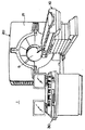
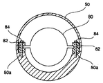
本発明の実施の形態4においては、前記X線管ユニット41のハウジング50とこのハウジング50内に収容したX線管を含むインサート部80とを絶縁構造としたことが特徴である。
The fourth embodiment of the present invention is characterized in that the
即ち、図12に示すように、X線管を含むインサート部80の両側の鍔部80aと、ハウジング50内に設けた対称配置の一対の段部50aとの間に、各々絶縁部材82を介在させて、インサート部80とハウジング50とを電気的に絶縁し、ボルト84により絶縁部材82を一対の段部50aの位置でハウジング50に固定する構造となっている。
That is, as shown in FIG. 12, the insulating
図13はハウジング50内において、アノードA、カソードKからなる陽極接地型のX線管を含むインサート部80と電源ユニット(定格150KV、600mA)45との回路構成例を示すものである。電源ユニット45とインサート部80とは一対のシールドケーブル85により接続されている。
FIG. 13 shows a circuit configuration example of an
図13によれば、インサート部80はそのケース内にアノードAとカソードKを含み、アノードAはそのケースに接続されている。そして、アノードAが接続されたインサート部80のケースは、一方のシールドケーブル85の芯線によって、ハウジング50に接触することとなく、電源ユニット45内で接地されている(これらを「回路系の接地」という。)。この接地は電源の正極側で行われている。
According to FIG. 13, the
カソードKは、インサート部80の外側、かつハウジング50の外側へ引き出され、他方のシールドケーブル85の芯線によって電源ユニット45内で電源の負極側へ接続されている。
The cathode K is pulled out to the outside of the
ハウジング50は、絶縁部材82及びボルト84で、絶縁してインサート部80を、内部に固定、保持している。そして、一対のシールドケーブル85のシールド線によって電源ユニット45のケースに接続され、かつ接地されている(これらを「ハウジング系の接地」と呼ぶ。)。
The
本実施の形態4の構成によれば、いわば、上記のように外側のハウジング系の接地電流が流れ、その内側の回路系の接地電流が流れ、かつ接地系統が、構造的に2重にされていることで、前記ハウジング50にX線管へ供給する高電圧が加わったり、管電流が流れたりすることを防止でき、保守作業時の感電を防止できる等、X線管装置1の安全性の向上を図ることができる。
According to the configuration of the fourth embodiment, the ground current of the outer housing system flows as described above, the ground current of the inner circuit system flows, and the ground system is structurally doubled. Therefore, it is possible to prevent a high voltage supplied to the X-ray tube from being applied to the
1 X線管装置
5 撮影口
10 寝台
11 駆動ユニット
20 架台
21 架台カバー
30 制御装置
40 回転体
41 X線管ユニット
44 冷却ユニット
45 電源ユニット
47 電源制御ユニット
48 回転体
49 放熱口
50 ハウジング
60 高圧コネクタ
70 高圧コネクタ
72 出入部
80 インサート部
DESCRIPTION OF
Claims (2)
前記アノードは前記インサート部のケースを介して前記電源ユニットの正極側へ接続され、
前記カソードが前記電源ユニットの負極側へ接続され、
前記電源ユニットの正極側が接地される、ことを特徴とするX線CT装置。 An insert portion for accommodating the anode and the cathode, the X-ray CT apparatus having an X-ray tube unit including a housing, a rotating body and a power unit for supplying electric power to the X-ray tube unit is mounted, including the insert portion In
The anode is connected to the positive side of the power supply unit through the case of the insert part,
The cathode is connected to the negative side of the power supply unit;
The positive electrode side is grounded, it X-ray CT apparatus according to claim of the power supply unit.
Priority Applications (1)
| Application Number | Priority Date | Filing Date | Title |
|---|---|---|---|
| JP2011091899A JP5367010B2 (en) | 2011-04-18 | 2011-04-18 | X-ray CT system |
Applications Claiming Priority (1)
| Application Number | Priority Date | Filing Date | Title |
|---|---|---|---|
| JP2011091899A JP5367010B2 (en) | 2011-04-18 | 2011-04-18 | X-ray CT system |
Related Parent Applications (1)
| Application Number | Title | Priority Date | Filing Date |
|---|---|---|---|
| JP33827598A Division JP4945020B2 (en) | 1998-11-27 | 1998-11-27 | X-ray tube device |
Related Child Applications (1)
| Application Number | Title | Priority Date | Filing Date |
|---|---|---|---|
| JP2013143040A Division JP5726241B2 (en) | 2013-07-08 | 2013-07-08 | X-ray CT apparatus and X-ray tube apparatus |
Publications (2)
| Publication Number | Publication Date |
|---|---|
| JP2011165673A JP2011165673A (en) | 2011-08-25 |
| JP5367010B2 true JP5367010B2 (en) | 2013-12-11 |
Family
ID=44596056
Family Applications (1)
| Application Number | Title | Priority Date | Filing Date |
|---|---|---|---|
| JP2011091899A Expired - Fee Related JP5367010B2 (en) | 2011-04-18 | 2011-04-18 | X-ray CT system |
Country Status (1)
| Country | Link |
|---|---|
| JP (1) | JP5367010B2 (en) |
Family Cites Families (5)
| Publication number | Priority date | Publication date | Assignee | Title |
|---|---|---|---|---|
| JPH05152093A (en) * | 1990-07-05 | 1993-06-18 | Toshiba Corp | X-ray tube, and x-ray ct scanner system using x-ray tube |
| FR2680938B1 (en) * | 1991-09-03 | 1993-11-26 | General Electric Cgr Sa | RADIOGENIC BLOCK WITH HIGH VOLTAGE SUPPLY DEVICE INTEGRATED IN THE SHEATH. |
| US5490196A (en) * | 1994-03-18 | 1996-02-06 | Metorex International Oy | Multi energy system for x-ray imaging applications |
| US5588035A (en) * | 1995-07-17 | 1996-12-24 | Varian Associates, Inc. | X-ray tube noise and vibration reduction |
| JPH09237694A (en) * | 1996-02-29 | 1997-09-09 | Toshiba Corp | Computerized tomography device |
-
2011
- 2011-04-18 JP JP2011091899A patent/JP5367010B2/en not_active Expired - Fee Related
Also Published As
| Publication number | Publication date |
|---|---|
| JP2011165673A (en) | 2011-08-25 |
Similar Documents
| Publication | Publication Date | Title |
|---|---|---|
| JP4482056B2 (en) | X-ray CT system | |
| CN106924887B (en) | Medical equipment | |
| CN106924889B (en) | Medical equipment | |
| US7933641B2 (en) | Medical examination and/or treatment apparatus with an electromagnet for navigating a medical instrument and an x-ray device for visual inspection during the navigation | |
| JP5911213B2 (en) | X-ray CT system | |
| US10462887B2 (en) | Radiation irradiation device | |
| US10381188B2 (en) | Radiographic image diagnostic apparatus and X-ray tube | |
| WO2014088041A1 (en) | X-ray computed tomography device | |
| JP2018015080A (en) | Radiation irradiation device | |
| US10478146B2 (en) | Radiation irradiation device | |
| KR20150073858A (en) | Rotating frame for the gantry of a computed tompgraphic machine, gantry and computed tompgraphic machine with such a rotating frame | |
| US20130010923A1 (en) | Intraoral radiation type x-ray photographing apparatus and method thereof | |
| US10966677B2 (en) | Radiography apparatus | |
| CN102456527B (en) | Apparatus and method for improved transient response in an electromagnetically controlled X-ray tube | |
| JP5367010B2 (en) | X-ray CT system | |
| JP5726241B2 (en) | X-ray CT apparatus and X-ray tube apparatus | |
| CN113303821A (en) | X-ray digital imaging system | |
| JP4945020B2 (en) | X-ray tube device | |
| JP4761898B2 (en) | X-ray computed tomography system | |
| US9968326B2 (en) | X-ray diagnostic apparatus | |
| CN216962475U (en) | Light X-ray digital imaging system | |
| JPH11188029A (en) | X-ray ct device | |
| JP7171319B2 (en) | X-ray CT device | |
| JPH05152093A (en) | X-ray tube, and x-ray ct scanner system using x-ray tube | |
| JP5388672B2 (en) | X-ray CT system |
Legal Events
| Date | Code | Title | Description |
|---|---|---|---|
| A621 | Written request for application examination |
Free format text: JAPANESE INTERMEDIATE CODE: A621 Effective date: 20110418 |
|
| A131 | Notification of reasons for refusal |
Free format text: JAPANESE INTERMEDIATE CODE: A131 Effective date: 20130219 |
|
| A521 | Request for written amendment filed |
Free format text: JAPANESE INTERMEDIATE CODE: A523 Effective date: 20130417 |
|
| A131 | Notification of reasons for refusal |
Free format text: JAPANESE INTERMEDIATE CODE: A131 Effective date: 20130507 |
|
| A521 | Request for written amendment filed |
Free format text: JAPANESE INTERMEDIATE CODE: A523 Effective date: 20130708 |
|
| TRDD | Decision of grant or rejection written | ||
| A01 | Written decision to grant a patent or to grant a registration (utility model) |
Free format text: JAPANESE INTERMEDIATE CODE: A01 Effective date: 20130820 |
|
| A61 | First payment of annual fees (during grant procedure) |
Free format text: JAPANESE INTERMEDIATE CODE: A61 Effective date: 20130910 |
|
| S111 | Request for change of ownership or part of ownership |
Free format text: JAPANESE INTERMEDIATE CODE: R313117 Free format text: JAPANESE INTERMEDIATE CODE: R313114 Free format text: JAPANESE INTERMEDIATE CODE: R313111 |
|
| R371 | Transfer withdrawn |
Free format text: JAPANESE INTERMEDIATE CODE: R371 |
|
| S111 | Request for change of ownership or part of ownership |
Free format text: JAPANESE INTERMEDIATE CODE: R313113 Free format text: JAPANESE INTERMEDIATE CODE: R313114 Free format text: JAPANESE INTERMEDIATE CODE: R313117 |
|
| R350 | Written notification of registration of transfer |
Free format text: JAPANESE INTERMEDIATE CODE: R350 |
|
| S533 | Written request for registration of change of name |
Free format text: JAPANESE INTERMEDIATE CODE: R313533 |
|
| R350 | Written notification of registration of transfer |
Free format text: JAPANESE INTERMEDIATE CODE: R350 |
|
| LAPS | Cancellation because of no payment of annual fees |