JP5361981B2 - Hot water storage water heater - Google Patents

Hot water storage water heater Download PDF

Info

Publication number
JP5361981B2
JP5361981B2 JP2011274756A JP2011274756A JP5361981B2 JP 5361981 B2 JP5361981 B2 JP 5361981B2 JP 2011274756 A JP2011274756 A JP 2011274756A JP 2011274756 A JP2011274756 A JP 2011274756A JP 5361981 B2 JP5361981 B2 JP 5361981B2
Authority
JP
Japan
Prior art keywords
hot water
water
storage tank
valve
water storage
Prior art date
Legal status (The legal status is an assumption and is not a legal conclusion. Google has not performed a legal analysis and makes no representation as to the accuracy of the status listed.)
Active
Application number
JP2011274756A
Other languages
Japanese (ja)
Other versions
JP2012052803A (en
Inventor
正樹 豊島
宗 平岡
明広 西田
Current Assignee (The listed assignees may be inaccurate. Google has not performed a legal analysis and makes no representation or warranty as to the accuracy of the list.)
Mitsubishi Electric Corp
Original Assignee
Mitsubishi Electric Corp
Priority date (The priority date is an assumption and is not a legal conclusion. Google has not performed a legal analysis and makes no representation as to the accuracy of the date listed.)
Filing date
Publication date
Application filed by Mitsubishi Electric Corp filed Critical Mitsubishi Electric Corp
Priority to JP2011274756A priority Critical patent/JP5361981B2/en
Publication of JP2012052803A publication Critical patent/JP2012052803A/en
Application granted granted Critical
Publication of JP5361981B2 publication Critical patent/JP5361981B2/en
Active legal-status Critical Current
Anticipated expiration legal-status Critical

Links

Images

Abstract

<P>PROBLEM TO BE SOLVED: To provide a storage water heater, suitably discharging expanded water and gas and decreasing energy loss. <P>SOLUTION: The storage water heater having a hot water storage tank 1 for storing hot water, a water supply pipe for supplying water to the hot water storage tank 1, and the hot water supply pipe for supplying high temperature water stored in the hot water storage tank 1 has the pressure releasing valve 20 arranged in the expanded water discharging pipe channel 33b connected to the water supply pipe and a separation membrane 24 for separating water and air arranged in the piping connected to the uppermost part of the hot water storage tank 1, the expanded water is discharged from the pressure releasing valve 20, gas is discharged from the separation membrane 24. <P>COPYRIGHT: (C)2012,JPO&amp;INPIT

Description

本発明は、貯湯式給湯器に関するものである。   The present invention relates to a hot water storage type water heater.

貯湯式給湯器において、貯湯タンク内の湯水を沸き上げると、水(お湯)の温度が上昇するに従って水の体積が膨張する。したがって、貯湯タンク及びこれに接続される配管回路内圧の上昇を防ぐために、膨張した量に相当する湯水(以下、膨張水と称す)を排出する必要がある。また、貯湯タンク内の湯水沸き上げに伴い、水に溶存していた空気も溶存できなくなり、一部ガス状態となる。貯湯タンク内や配管回路内にこのガスが残留すると、腐食の原因となったり、出湯時の給湯水にガスが混ざって給湯端の蛇口で高温の湯が飛び散ったり、周辺の物に飛散して濡れたり、不快な音が発生するなどの利用者に不都合な現象を引き起こす可能性があった。このようなことから、貯湯タンク及び配管回路内から膨張水とガスを排出する必要がある。   When boiling hot water in a hot water storage tank in a hot water storage type water heater, the volume of water expands as the temperature of the water (hot water) rises. Therefore, in order to prevent an increase in the internal pressure of the hot water storage tank and the piping circuit connected thereto, it is necessary to discharge hot water corresponding to the expanded amount (hereinafter referred to as expanded water). In addition, as the hot water in the hot water tank is boiled, the air dissolved in the water cannot be dissolved, and a part of the air is in a gas state. If this gas remains in the hot water storage tank or piping circuit, it may cause corrosion, gas may be mixed with the hot water at the time of hot water, and hot water may be splashed at the hot water tap. It may cause inconveniences to users such as getting wet or unpleasant sounds. For this reason, it is necessary to discharge the expanded water and gas from the hot water storage tank and the piping circuit.

従来より、膨張水及び発生したガスを、貯湯タンク内圧上昇によって開弁する圧力逃し弁により排出する方法が用いられてきた。ところが、圧力逃し弁を貯湯タンク上部に設置すると、沸き上げた高温水も同時に排出してしまうことになり、貯湯エネルギーのロスを招いてしまう。   Conventionally, a method has been used in which the expanded water and the generated gas are discharged by a pressure relief valve that opens when the internal pressure of the hot water storage tank increases. However, if a pressure relief valve is installed in the upper part of the hot water storage tank, the heated hot water will be discharged at the same time, resulting in a loss of hot water storage energy.

高温水をなるべく排出しない貯湯式温水器として、「加熱源により加熱された温水を貯湯する貯湯タンクに接続された配管を介して温水を給湯するようにした貯湯式温水器において、前記貯湯タンクからの高温水とこの貯湯タンク下部からの低温水とを混合する混合弁を介して過圧力逃がし弁を接続した」ものがある。またこの先行文献においては、「前記貯湯タンクへの貯湯運転時間を算出する算出手段と、前記混合弁を初めにこの貯湯タンク下部からの低温水が極力多く流れるような開度に制御すると共に貯湯運転時間が経過する前にこの貯湯タンク上部からの高温水が極力多く流れるような開度に制御する制御装置」を設けている(例えば、特許文献1参照)。   As a hot water type hot water heater that discharges hot water as much as possible, in the hot water type hot water heater that supplies hot water through a pipe connected to a hot water storage tank that stores hot water heated by a heating source, An overpressure relief valve is connected via a mixing valve that mixes the hot water in the hot water and the low temperature water from the lower part of the hot water storage tank. Further, in this prior document, “a calculation means for calculating the hot water storage operation time to the hot water storage tank, and the mixing valve is controlled to an opening degree at which low temperature water from the lower portion of the hot water storage tank first flows as much as possible and hot water storage A control device is provided that controls the opening so that high-temperature water from the upper part of the hot water tank flows as much as possible before the operation time elapses (see, for example, Patent Document 1).

特開2006−145047号公報(第3−6頁、第1図)JP 2006-145047 A (page 3-6, FIG. 1)

しかし、従来の発明では、蛇口とこれに繋がる給湯側混合弁の出口に圧力逃し弁を設けているので、混合弁が高温水側開度大の状態で停電した場合には、混合弁の制御が行えない。そのため、この状態にあるときに使用者が蛇口を開くと、使用者の意に反して高温水が出湯してしまうおそれがあった。また、停電が起きなくとも、膨張水やガスを排出するために混合弁を水側あるいは高温水側開度大に固定しているときに使用者が蛇口から出湯した場合には、水側あるいは高温水側全開の状態から目的の出湯温度となるよう混合弁の制御を行わなければならないため、目標の混合温度に到達するまで時間が長くかかるという不都合があった。   However, in the conventional invention, since the pressure relief valve is provided at the outlet of the faucet and the hot water supply side mixing valve connected to the faucet, the control of the mixing valve is performed in the case of a power failure when the mixing valve is in a high temperature water side opening degree. Cannot be done. For this reason, when the user opens the faucet in this state, there is a risk that high-temperature water will come out against the user's will. Even if a power outage does not occur, if the user discharges hot water from the faucet while the mixing valve is fixed at a large water side or high temperature water side to discharge the expanded water or gas, the water side or Since it is necessary to control the mixing valve so that the target hot water temperature is reached from a state where the hot water side is fully open, it takes a long time to reach the target mixing temperature.

また、従来の発明では、貯湯タンク沸上げ途中で混合弁を水側から高温水側に切り替え、沸上げ最終過程において貯湯回路内のガスを排出していたが、ガスの発生を検知しているわけではないため、制御が不適切な場合にはガスが残留してしまう。また、混合弁の水側から高温水側への切り替えを早めた場合には、ガスを多く排出することができるが、同時に排出される高温水の量が増加し、貯湯エネルギーのロスが増大してしまう。   In the conventional invention, the mixing valve is switched from the water side to the high-temperature water side during boiling of the hot water tank, and the gas in the hot water storage circuit is discharged in the final boiling process, but the generation of gas is detected. This is not to say that gas will remain if control is inadequate. Also, if the mixing valve is switched from the water side to the high temperature water side earlier, more gas can be discharged, but at the same time, the amount of high temperature water discharged increases and the loss of hot water storage energy increases. End up.

また、出湯用混合弁が2系統、すなわち、一般給湯側(給湯端:蛇口)と風呂給湯側(給湯端:浴槽)が存在する貯湯式温水器においては、貯湯タンク最上部から混合弁に至る配管が2系統存在することになる。例えば、貯湯タンク上部から途中で2分岐する、もしくは、貯湯タンク上部から2系統が独立接続される、などの構成がある。この場合、圧力逃し弁を風呂給湯側混合弁出口に設置して風呂側回路からガスを排出したとしても、一般給湯側配管のガスは排出が行われないため、残留してしまうという不都合があった。   In addition, in a hot water storage water heater having two hot water mixing valves, that is, a general hot water supply side (hot water supply end: faucet) and a bath hot water supply side (hot water supply end: bathtub), the hot water tank reaches the mixing valve from the top. Two pipes exist. For example, there are configurations such as two branches on the way from the upper part of the hot water tank, or two systems are independently connected from the upper part of the hot water tank. In this case, even if a pressure relief valve is installed at the outlet of the hot water supply side mixing valve and the gas is discharged from the bath side circuit, the gas in the general hot water supply side piping is not discharged, so there is a disadvantage that it remains. It was.

また、従来の発明の構成において、例えば、制御方法を変更し、混合弁の開度を水側と高温水側の中間開度にすることもできる。この場合、貯湯タンク沸上げ中に、水とガスとを同時に排出することができ、前記混合弁の水側から高温水側への切り替え制御が不要となる。しかし、従来の発明の構成では、圧力逃し弁に繋がる混合弁の入口側に逆止弁が設けられていないため、沸上げ運転時に中間開度の混合弁をバイパスして低温水が貯湯タンク上部へ流入してしまい、高温水と混合することによって貯湯温度が低下し、貯湯エネルギーがロスするという不都合が発生する可能性があった。   Further, in the configuration of the conventional invention, for example, the control method can be changed so that the opening degree of the mixing valve is set to an intermediate opening degree between the water side and the high temperature water side. In this case, water and gas can be discharged simultaneously during boiling of the hot water storage tank, and switching control from the water side to the high temperature water side of the mixing valve is not necessary. However, in the configuration of the conventional invention, since the check valve is not provided on the inlet side of the mixing valve connected to the pressure relief valve, the low-temperature water is bypassed the intermediate opening mixing valve during the boiling operation, Inflow into the water and mixing with high-temperature water may cause a disadvantage that the hot water storage temperature is lowered and the hot water storage energy is lost.

本発明は、上述のような課題を解決するためになされたもので、膨張水及びガスを適切に排出することができ、かつ、エネルギーロスの少ない貯湯式給湯器を提供するものである。   The present invention has been made in order to solve the above-described problems, and provides a hot water storage type hot water heater that can appropriately discharge expanded water and gas and has little energy loss.

本発明に係る貯湯式給湯器は、湯水を貯留する貯湯タンクと、前記貯湯タンクに給水する給水管と、前記貯湯タンクに貯留された高温水を出湯する出湯管とを有する貯湯式給湯器において、前記出湯管からの高温水と前記給水管からの水とを混合する給湯用混合弁と、前記給水管の前記給湯用混合弁よりも上流側に設けられた圧力逃し弁と、前記貯湯タンクの最上部に接続された配管もしくは高温水が流れる高温側配管に設けられた水と空気を分離する分離膜とを有し、前記圧力逃し弁から膨張水を排出し、前記分離膜から気体を排出するものである。 A hot water storage type water heater according to the present invention is a hot water storage type water heater having a hot water storage tank for storing hot water, a water supply pipe for supplying water to the hot water storage tank, and a hot water discharge pipe for discharging hot water stored in the hot water storage tank. A hot water mixing valve for mixing hot water from the hot water pipe and water from the water supply pipe , a pressure relief valve provided upstream of the hot water mixing valve in the water supply pipe , and the hot water storage tank A separation membrane that separates air and water provided in a pipe connected to the top of the pipe or a high-temperature side pipe through which high-temperature water flows, and discharges expanded water from the pressure relief valve, and allows gas to flow from the separation membrane. To be discharged.

本発明に係る貯湯式給湯器は、出湯管とは異なる配管で圧力逃し弁を設けたので、出湯動作とは独立して膨張水排出処理を行うことができる。したがって、膨張水処理中に使用者が蛇口などから湯水を出そうとした場合においても、適切な温度の湯水を供給することができる。   Since the hot water storage type water heater according to the present invention is provided with the pressure relief valve by a pipe different from the hot water discharge pipe, the expanded water discharge process can be performed independently of the hot water discharge operation. Therefore, even when the user tries to take out hot water from a faucet or the like during the expansion water treatment, hot water at an appropriate temperature can be supplied.

本発明の実施の形態1を示す貯湯式給湯器のシステム構成図である。It is a system configuration | structure figure of the hot water storage type water heater which shows Embodiment 1 of this invention. 本発明の実施の形態1を示す制御ブロック図である。It is a control block diagram which shows Embodiment 1 of this invention. 本発明の実施の形態1を示す圧力逃し弁の動作説明図である。It is operation | movement explanatory drawing of the pressure relief valve which shows Embodiment 1 of this invention. 本発明の実施の形態2を示す貯湯式給湯器のシステム構成図である。It is a system block diagram of the hot water storage type water heater which shows Embodiment 2 of this invention. 本発明の実施の形態3を示す貯湯式給湯器のシステム構成図である。It is a system block diagram of the hot water storage type water heater which shows Embodiment 3 of this invention. 本発明の実施の形態4を示す貯湯式給湯器のシステム構成図である。It is a system block diagram of the hot water storage type water heater which shows Embodiment 4 of this invention.

実施の形態1.
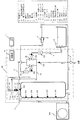
図1は、本発明の実施の形態1に係る貯湯式給湯器全体のシステム構成図である。図1において、本実施の形態1に係る貯湯式給湯器は、貯湯ユニット100と熱源ユニット200とで構成される。貯湯ユニット100には、浴槽5、混合栓6、及びリモコン7が接続されている。浴槽5は、風呂給湯側混合弁2bから供給される湯水を貯留する浴槽である。混合栓6は、一般給湯側混合弁2aから給湯された高温水と水源から供給される市水とを混合して給湯する混合栓であり、例えば、蛇口やシャワーなどが接続される場合がある。リモコン7は、給湯温度の設定や浴槽への給湯操作などの貯湯式給湯器への情報の入力や、運転状況の表示などを行うものである。なお、リモコン7は、風呂用や台所用など、複数個を設置してもよい。
Embodiment 1 FIG.
FIG. 1 is a system configuration diagram of the entire hot water storage type hot water heater according to Embodiment 1 of the present invention. In FIG. 1, a hot water storage type water heater according to the first embodiment includes a hot water storage unit 100 and a heat source unit 200. To the hot water storage unit 100, a bathtub 5, a mixing plug 6, and a remote controller 7 are connected. The bathtub 5 is a bathtub for storing hot water supplied from the hot water supply side mixing valve 2b. The mixing plug 6 is a mixing plug that supplies hot water by mixing hot water supplied from the general hot water supply side mixing valve 2a and city water supplied from a water source. For example, a faucet or a shower may be connected. . The remote controller 7 is used to input information to the hot water storage type water heater such as setting the hot water temperature and hot water supply operation to the bathtub, and to display the operation status. A plurality of remote controllers 7 may be installed, such as for baths and kitchens.

熱源ユニット200は、市水温度の水(以下、水もしくは低温水と称す)を目標の貯湯温度まで昇温加熱する熱交換器などの加熱器(図示せず)を内蔵している。加熱器としては、例えば、HFCやCO2などを冷媒としたヒートポンプを用いる。なお、ヒートポンプに代えて、加熱源を電気ヒータなどに置き換えてもよく、また、加熱源を貯湯タンク1に内蔵する構成としてもよい。   The heat source unit 200 incorporates a heater (not shown) such as a heat exchanger that heats and heats water at a city water temperature (hereinafter referred to as water or low-temperature water) to a target hot water storage temperature. As the heater, for example, a heat pump using HFC or CO2 as a refrigerant is used. Instead of the heat pump, the heating source may be replaced with an electric heater or the like, or the heating source may be built in the hot water storage tank 1.

貯湯ユニット100は、貯湯タンク1、一般給湯側混合弁2a、風呂給湯側混合弁2b(以下、両者を併せて混合弁2a、2bと称す場合がある)、減圧弁3、電磁弁4、圧力逃し弁20が配管接続されて構成される。また、貯湯ユニット100には後述の複数のセンサ(11a、11b、12a〜12d、13a〜13e)が備えられており、制御部10は、これらセンサの検出した値とリモコン7からの指示や熱源ユニット200の運転状況に基づいて、本貯湯式給湯器の制御を行う。
貯湯タンク1は、ステンレスなどの金属製、もしくは樹脂製であり、図示しない断熱材が配置されており、高温の湯(以下、高温水と称す)を長時間に渡って保温できるものである。
The hot water storage unit 100 includes a hot water storage tank 1, a general hot water supply side mixing valve 2a, a bath hot water supply side mixing valve 2b (hereinafter, both may be referred to as mixing valves 2a and 2b), a pressure reducing valve 3, a solenoid valve 4, and a pressure. The relief valve 20 is configured by pipe connection. The hot water storage unit 100 is provided with a plurality of sensors (11a, 11b, 12a to 12d, 13a to 13e) which will be described later, and the controller 10 detects the values detected by these sensors, instructions from the remote controller 7, and heat sources. Based on the operating condition of the unit 200, the hot water storage hot water heater is controlled.
The hot water storage tank 1 is made of metal such as stainless steel or resin, and is provided with a heat insulating material (not shown), which can keep hot hot water (hereinafter referred to as high temperature water) for a long time.

続いて、配管構成について説明する。なお、図1に示す各矢印は、湯水(低温水または高温水)の移動方向を示しており、白抜き矢印は膨張水またはガスの排出を示している。   Next, the piping configuration will be described. In addition, each arrow shown in FIG. 1 has shown the moving direction of hot water (low temperature water or high temperature water), and the white arrow has shown discharge | emission of expansion water or gas.

水源から供給された水は、減圧弁3を通過した後、貯湯タンク1に繋がる配管と、混合弁2a、2bに繋がる配管と、混合栓6に繋がる配管とに3分岐される。   After passing through the pressure reducing valve 3, the water supplied from the water source is branched into three branches: a pipe connected to the hot water storage tank 1, a pipe connected to the mixing valves 2 a and 2 b, and a pipe connected to the mixing plug 6.

貯湯タンク1の下部に導入された水は、熱源ユニット200へ送水され、熱源ユニット200で目標温度まで加熱昇温された後に、貯湯タンク1上部に送水される。ここで、貯湯タンク1と熱源ユニット200間の水の循環は、熱源ユニット200に内蔵される図示しないポンプを動力として行われる。なお、ポンプは熱源ユニット200に内蔵させず、貯湯ユニット100に内蔵する構成としてもよい。   The water introduced into the lower part of the hot water storage tank 1 is sent to the heat source unit 200, heated to the target temperature by the heat source unit 200, and then supplied to the upper part of the hot water storage tank 1. Here, the circulation of water between the hot water storage tank 1 and the heat source unit 200 is performed using a pump (not shown) built in the heat source unit 200 as power. The pump may be built in the hot water storage unit 100 instead of being built in the heat source unit 200.

貯湯タンク1の最上部には、高温水を取り出す取り出し部41が設けられ、分岐部42より分岐して出湯管路31と膨張水排出管路33とが設けられている。出湯管路31は、一般給湯側混合弁2a及び風呂給湯側混合弁2bに高温水を分配する。一般給湯側混合弁2a及び風呂給湯側混合弁2bには、水源からの水配管も接続されており、高温水と低温水とが混合される。一般給湯側混合弁2aを経由した湯水は、混合栓6にて水源からの水と混合され、蛇口やシャワーなどから供給される。風呂給湯側混合弁2bを経由した湯水は、電磁弁4を介して浴槽5に供給される。   At the uppermost part of the hot water storage tank 1, a take-out part 41 for taking out high-temperature water is provided, and a hot water discharge line 31 and an expanded water discharge line 33 are provided by branching from the branch part 42. The hot water supply pipe 31 distributes high temperature water to the general hot water supply side mixing valve 2a and the bath hot water supply side mixing valve 2b. A water pipe from a water source is also connected to the general hot water supply side mixing valve 2a and the bath hot water supply side mixing valve 2b, and high temperature water and low temperature water are mixed. Hot water passing through the general hot water supply side mixing valve 2a is mixed with water from a water source at the mixing tap 6 and supplied from a faucet or a shower. Hot water passing through the bath hot water supply side mixing valve 2 b is supplied to the bathtub 5 via the electromagnetic valve 4.

貯湯タンク1の上方には、膨張水排出管路33を経由して圧力逃し弁20が設けられている。圧力逃し弁20は、出湯管路31よりも高い位置に設けられている。圧力逃し弁20の入口管は分岐部43で分岐し、第一の端部が膨張水排出管路33に、第二の端部が給水管路32に接続されており、圧力逃し弁20の出口側に繋がる配管の端は、大気に開放されている。給水管路32は、水源から供給される水を導く配管である。   Above the hot water storage tank 1, a pressure relief valve 20 is provided via an expanded water discharge pipe 33. The pressure relief valve 20 is provided at a position higher than the outlet hot water pipe 31. The inlet pipe of the pressure relief valve 20 branches off at the branch part 43, the first end is connected to the expansion water discharge pipe 33, and the second end is connected to the water supply pipe 32. The end of the pipe connected to the outlet side is open to the atmosphere. The water supply pipe 32 is a pipe that guides water supplied from a water source.

また、分岐部42から分岐部43に至る配管上には、貯湯タンク1から近い順に、逆止弁22、オリフィス21が設けられている。逆止弁22は、給水管路32から流入する低温水が、貯湯タンク1に流れ込むことを防ぐためのものである。オリフィス21は、膨張水排出管路33の流路抵抗を調節する。なお、オリフィス21を設ける代わりに、該当箇所の配管パイプを一部絞ったり、該当箇所に細管を設けるなど、他の減圧手段を設けてもよい。   In addition, a check valve 22 and an orifice 21 are provided on the piping from the branching portion 42 to the branching portion 43 in order from the hot water storage tank 1. The check valve 22 is for preventing low temperature water flowing from the water supply pipe 32 from flowing into the hot water storage tank 1. The orifice 21 adjusts the flow resistance of the expanded water discharge pipe 33. Instead of providing the orifice 21, other decompression means may be provided, such as partially narrowing the pipe pipe at the corresponding location or providing a narrow tube at the relevant location.

なお、図1では、混合栓6が一つである場合を例に挙げたが、例えば台所や洗面所の蛇口、浴室のカラン兼シャワーなど複数設けてもよい。また、混合弁の数を増やして、それぞれの混合栓に対応する構成としてもよい。また、貯湯タンク1は1本の構成としたが、2本以上の貯湯タンクを直列もしくは並列に接続する構成としてもよい。また、混合弁2a、2bは、例えばサーボモータ等の駆動源により弁体を駆動する電動弁であり、弁体が動くことにより湯と水の混合比率を調整して給湯温度を制御できる構造のものである。   In addition, although the case where the number of the mixing plugs 6 is one was illustrated in FIG. 1, you may provide two or more, such as a faucet of a kitchen or a washroom, a currant / shower of a bathroom, for example. Moreover, it is good also as a structure corresponding to each mixing stopper by increasing the number of mixing valves. Moreover, although the hot water storage tank 1 is configured as one, it may be configured such that two or more hot water storage tanks are connected in series or in parallel. The mixing valves 2a and 2b are electric valves that drive the valve body by a drive source such as a servo motor, for example, and have a structure that can control the hot water supply temperature by adjusting the mixing ratio of hot water and water by moving the valve body. Is.

次に、貯湯ユニット100に設けられたセンサ類と制御部について説明する。
一般給湯側混合弁2aの出口側には流量センサ11aが、風呂給湯側混合弁2bの出口側には流量センサ11bがそれぞれ設けられており、混合弁2a、2bから出る湯水の流量を計測する。
また、配管内を流れる湯水の温度を計測するための温度センサ12a〜12dが設けられている。温度センサ12aは、一般給湯側混合弁2aの出口側の給湯温度を計測し、温度センサ12bは、風呂給湯側混合弁2bの出口側の給湯温度を計測する。
また、水源から混合弁2a、2bに至る配管には、混合弁2a、2bに給水される水の温度を計測するための温度センサ12cが設けられている。
また、貯湯タンク1の取り出し部41の近傍には、給湯温度を計測するための温度センサ12dが設けられている。なお、温度センサ12dは、取り出し部41の配管上に設けるほかに、貯湯タンク1上部の缶体表面に設けてもよく、また、貯湯タンク1上部缶体内部の湯温を直接測定する構成としてもよい。
Next, sensors and a control unit provided in the hot water storage unit 100 will be described.
A flow rate sensor 11a is provided on the outlet side of the general hot water supply side mixing valve 2a, and a flow rate sensor 11b is provided on the outlet side of the bath hot water supply side mixing valve 2b. The flow rate sensor 11b measures the flow rate of hot water from the mixing valves 2a and 2b. .
In addition, temperature sensors 12a to 12d are provided for measuring the temperature of hot water flowing in the pipe. The temperature sensor 12a measures the hot water supply temperature on the outlet side of the general hot water supply side mixing valve 2a, and the temperature sensor 12b measures the hot water supply temperature on the outlet side of the bath hot water supply side mixing valve 2b.
Moreover, the temperature sensor 12c for measuring the temperature of the water supplied to mixing valve 2a, 2b is provided in piping from the water source to mixing valve 2a, 2b.
Further, a temperature sensor 12d for measuring the hot water supply temperature is provided in the vicinity of the take-out portion 41 of the hot water storage tank 1. The temperature sensor 12d may be provided on the surface of the can body at the upper part of the hot water storage tank 1 in addition to being provided on the pipe of the take-out portion 41, and the hot water temperature in the upper body of the hot water storage tank 1 may be directly measured. Also good.

また貯湯タンク1には、貯湯水温を測定するための温度センサ13a〜13eが設けられており、貯湯タンク1内の各箇所の湯温を計測する。これらの温度情報から、貯湯タンク1に蓄熱される貯湯熱量を把握することができる。なお、温度センサ13a〜13eは、配管やタンクの表面にロー付け、溶接、ねじ固定、フォルダ固定するなどの方法や、水温を直接測るように配管やタンクの内部にセンサを内没させる設置方法など、いずれの方法を用いて設置してもよい。   The hot water storage tank 1 is provided with temperature sensors 13 a to 13 e for measuring the hot water temperature, and measures the hot water temperature at each location in the hot water storage tank 1. From these temperature information, the amount of stored hot water stored in the hot water storage tank 1 can be grasped. The temperature sensors 13a to 13e are brazed to the surface of the pipe or tank, welded, screwed, or fixed to the folder, or installed so that the sensor is immersed in the pipe or tank so that the water temperature can be directly measured. You may install using any method.

制御部10は、貯湯ユニット100に内蔵されており、温度や流量などのセンサ類の測定を行う測定部(図示せず)、測定結果に基づき演算、比較、判定などの処理を行う演算部(図示せず)、演算結果に基づいて電磁弁4等の弁類を駆動する駆動部(図示せず)、熱源ユニット200と運転情報などを送受信する送受信部(図示せず)を構成要素に含む。
また、演算部によって得られた結果や、演算に用いる近似式、データテーブルなどを記憶する記憶部(図示せず)も内蔵しており、必要に応じてこれらの記憶内容を参照、書き換えることができる。上記の測定、演算、駆動などの各処理はマイコンにより行われ、記憶部は半導体メモリなどによって構成される。
また、制御部10は、図示しない出力部を備え、マイコンによる処理結果をLEDやモニターなどに表示したり、警告音などを出力したり、電話回線、LAN回線、無線などの通信手段(図示せず)により遠隔地へ情報を出力するなどの出力動作が可能である。
また、制御部10は、図示しない入力部を備え、リモコン7や図示しないスイッチ類からの操作入力、もしくは電話回線、LAN回線、無線などの通信手段(図示せず)からの通信データを入力することができる。
The control unit 10 is built in the hot water storage unit 100, and includes a measurement unit (not shown) that measures sensors such as temperature and flow rate, and a calculation unit that performs processing such as calculation, comparison, and determination based on the measurement result ( The constituent elements include a drive unit (not shown) for driving valves such as the electromagnetic valve 4 based on the calculation result, and a transmission / reception unit (not shown) for transmitting / receiving operation information with the heat source unit 200 based on the calculation result. .
It also has a built-in storage unit (not shown) that stores the results obtained by the calculation unit, approximate expressions used in calculations, data tables, etc., and these stored contents can be referenced and rewritten as necessary. it can. Each processing such as measurement, calculation, and driving is performed by a microcomputer, and the storage unit is configured by a semiconductor memory or the like.
In addition, the control unit 10 includes an output unit (not shown), displays a processing result by the microcomputer on an LED, a monitor, etc., outputs a warning sound, etc., and communication means (not shown) such as a telephone line, a LAN line, and a radio. To output information to a remote location.
The control unit 10 includes an input unit (not shown), and inputs operation data from the remote controller 7 and switches (not shown) or communication data from a communication means (not shown) such as a telephone line, a LAN line, and a radio. be able to.

図2は、本実施の形態1に係る制御ブロック図である。制御部10は、流量センサ11a、11b、温度センサ12a〜12d、13a〜13eと、それぞれ通信ケーブルにより有線接続または無線接続されており、信号の授受が可能である。また、熱源ユニット200、リモコン7と、それぞれ有線接続または無線接続されており、制御信号の送受信が可能である。また、制御部10は、混合弁2a、2b、電磁弁4と有線接続または無線接続されており、センサ類からの情報や熱源ユニット200の運転状況、リモコン7からの運転指示などの情報に基づいて、混合弁2a、2b、電磁弁4の動作制御を行う。
なお、上記構成例では制御部10を貯湯ユニット100に内蔵する構成としたが、貯湯ユニット100にメイン制御部を、熱源ユニット200に制御部の機能の一部をもつサブ制御部を設けて、メイン制御部とサブ制御部間でデータ通信を行うことにより連携処理を行う構成としてもよい。また、リモコン7にこれらの機能を備える構成や、貯湯ユニット100の外部に同等の機能をもつ制御部を別置する構成としてもよく、同等の機能を実現するものであれば、その設置等の構成については問わない。
FIG. 2 is a control block diagram according to the first embodiment. The control unit 10 is wired or wirelessly connected to the flow sensors 11a and 11b and the temperature sensors 12a to 12d and 13a to 13e via communication cables, respectively, and can exchange signals. The heat source unit 200 and the remote controller 7 are wired or wirelessly connected, and can transmit and receive control signals. The control unit 10 is wired or wirelessly connected to the mixing valves 2 a and 2 b and the electromagnetic valve 4, and is based on information such as information from sensors, the operation status of the heat source unit 200, and operation instructions from the remote controller 7. Then, the operation control of the mixing valves 2a and 2b and the electromagnetic valve 4 is performed.
In the above configuration example, the control unit 10 is built in the hot water storage unit 100, but the hot water storage unit 100 is provided with a main control unit, and the heat source unit 200 is provided with a sub-control unit having a part of the function of the control unit. It is good also as a structure which performs a cooperation process by performing data communication between a main control part and a sub control part. Moreover, it is good also as a structure which equips the remote control 7 with these functions, and the structure which separately arrange | positions the control part which has an equivalent function outside the hot water storage unit 100, if an equivalent function is implement | achieved, the installation etc. It does not ask about composition.

上記のように構成した貯湯式給湯器における給湯動作について説明する。
貯湯タンク1への貯湯は、予めリモコン7で目標沸上げ温度を設定しておき、深夜時間帯に熱源ユニット200のヒートポンプ熱源により貯湯タンク1の水温を目標沸上げ温度まで沸き上げることにより行う。また、昼間時間帯に貯湯量が不足する場合は、熱源ユニット200を運転して貯湯タンク1に追加貯湯することも可能である。
The hot water supply operation in the hot water storage type water heater configured as described above will be described.
Hot water storage in the hot water storage tank 1 is performed by setting a target boiling temperature in advance with the remote controller 7 and boiling the water temperature in the hot water storage tank 1 to the target boiling temperature by the heat pump heat source of the heat source unit 200 in the midnight time zone. In addition, when the amount of hot water storage is insufficient during the daytime, it is possible to operate the heat source unit 200 to store additional hot water in the hot water storage tank 1.

このようにして貯湯した貯湯タンク1から一般給湯側へ給湯を行う場合において、使用者は、給湯温度を予めリモコン7で設定しておく。使用者が混合栓6を開くと、制御部10は、一般給湯側の温度センサ12aの検出温度が設定された給湯温度となるように一般給湯側混合弁2aを制御して高温水と水とを指定された給湯温度(例えば42℃)となるように混合する。これにより、混合栓6から指定温度で給湯が開始される。   When hot water is supplied from the hot water storage tank 1 thus stored to the general hot water supply side, the user sets the hot water supply temperature in advance using the remote controller 7. When the user opens the mixing tap 6, the control unit 10 controls the general hot water supply side mixing valve 2 a so that the temperature detected by the temperature sensor 12 a on the general hot water supply side becomes the set hot water temperature. Are mixed to a specified hot water supply temperature (for example, 42 ° C.). As a result, hot water supply is started from the mixing plug 6 at the specified temperature.

また、浴槽5へ給湯を行う場合においては、使用者は、給湯温度及び給湯湯量を予めリモコン7で設定しておく。ここで、浴槽5への給湯方法には、湯張り、高温差し湯、足し湯、注水の4つのパターンがある。   When hot water is supplied to the bathtub 5, the user sets the hot water supply temperature and the amount of hot water supply with the remote controller 7 in advance. Here, the hot water supply method to the bathtub 5 has four patterns of hot water filling, high temperature hot water, additional hot water, and water injection.

まず、湯張り動作について説明する。
使用者がリモコン7の「湯張り」スイッチを押すと、湯張りの指示が制御部10へ出力される。湯張り指示を受けた制御部10は、風呂側の温度センサ12bでの検出温度が設定された給湯温度となるように風呂給湯側混合弁2bを制御し、高温水と水とを、指定された給湯温度となるように混合する。また、電磁弁4を開いて、浴槽5への湯張りを開始する。湯張りを開始した後は、流量センサ11bにより積算流量をカウントし、予め設定された給湯湯量に達するまで湯張りを継続する。積算湯量が設定された給湯湯量に達すると、電磁弁4を閉じて湯張りを完了する。
First, the hot water filling operation will be described.
When the user presses the “hot water” switch on the remote controller 7, a hot water instruction is output to the control unit 10. Upon receiving the hot water filling instruction, the control unit 10 controls the hot water supply side mixing valve 2b so that the temperature detected by the temperature sensor 12b on the bath side becomes the set hot water supply temperature, and high temperature water and water are designated. Mix so that the hot water temperature is high. Moreover, the solenoid valve 4 is opened and the filling of the hot water to the bathtub 5 is started. After the hot water filling is started, the integrated flow rate is counted by the flow sensor 11b, and the hot water filling is continued until a preset hot water supply amount is reached. When the accumulated hot water amount reaches the set hot water amount, the solenoid valve 4 is closed to complete the hot water filling.

次に、高温差し湯動作について説明する。
使用者がリモコン7の「高温差し湯」スイッチを押すと、指示が制御部10へ出力される。高温差し湯指示を受けた制御部10は、浴槽5側の温度センサ12bの検出温度が高温(例えば60℃)となるように、風呂給湯側混合弁2bを制御し、高温水と水とを、指定された給湯温度となるように混合する。また、電磁弁4を開いて、浴槽5への高温差し湯を開始する。浴槽5への高温差し湯を開始した後は、流量センサ11bにより積算流量をカウントし、一定量(例えば20L)に達するまで高温差し湯を継続する。積算湯量が設定された湯量に達すると、電磁弁4を閉じて高温差し湯を完了する。
Next, the hot water hot water operation will be described.
When the user presses the “hot hot water” switch on the remote controller 7, an instruction is output to the control unit 10. Upon receiving the hot water hot water instruction, the control unit 10 controls the hot water supply side mixing valve 2b so that the temperature detected by the temperature sensor 12b on the bathtub 5 side becomes high temperature (for example, 60 ° C.). Mix to the specified hot water temperature. Moreover, the solenoid valve 4 is opened and the hot water supply to the bathtub 5 is started. After the hot water supply to the bathtub 5 is started, the integrated flow rate is counted by the flow sensor 11b, and the hot water supply is continued until a certain amount (for example, 20 L) is reached. When the accumulated hot water amount reaches the set hot water amount, the solenoid valve 4 is closed to complete the hot water supply.

次に、足し湯動作について説明する。
使用者がリモコン7の「足し湯」スイッチを押すと、指示が制御部10へ出力される。足し湯指示を受けた制御部10は、浴槽5側の温度センサ12bの検出温度がリモコン7で設定されている浴槽湯温となるように風呂給湯側混合弁2bを制御するとともに、電磁弁4を開いて浴槽5への足し湯を開始する。浴槽5への足し湯開始後、流量センサ11bにより積算流量をカウントし、一定量(例えば20L)に到達すると、電磁弁4を閉じて足し湯を完了する。
Next, the addition hot water operation will be described.
When the user presses the “Additional hot water” switch on the remote controller 7, an instruction is output to the control unit 10. The control unit 10 that has received the additional hot water instruction controls the hot water supply side mixing valve 2b so that the temperature detected by the temperature sensor 12b on the bathtub 5 side becomes the bathtub hot water temperature set by the remote controller 7, and the electromagnetic valve 4 Is opened to start adding hot water to the bathtub 5. After the start of adding hot water to the bathtub 5, the integrated flow rate is counted by the flow sensor 11b, and when reaching a certain amount (for example, 20L), the solenoid valve 4 is closed to complete the adding hot water.

次に、注水動作について説明する。
使用者がリモコン7の「注水」スイッチを押すと、指示が制御部10へ出力される。注水指示を受けた制御部10は、温度センサ12bの検出温度が市水温となるように風呂給湯側混合弁2bを制御するとともに、電磁弁4を開いて浴槽5への注水を開始する。浴槽5への注水開始後、流量センサ11bにより積算流量をカウントし、一定量(例えば20L)に到達すると、電磁弁4を閉じて注水を完了する。
Next, the water injection operation will be described.
When the user presses the “water injection” switch on the remote controller 7, an instruction is output to the control unit 10. Upon receiving the water injection instruction, the controller 10 controls the bath hot water supply side mixing valve 2b so that the temperature detected by the temperature sensor 12b becomes the city water temperature, and opens the electromagnetic valve 4 to start water injection into the bathtub 5. After the start of water injection into the bathtub 5, the integrated flow rate is counted by the flow sensor 11b, and when reaching a certain amount (for example, 20L), the electromagnetic valve 4 is closed to complete the water injection.

貯湯する際に貯湯タンク1の低温の水を高温に沸き上げると、水の体積が膨張する。これは、水の密度が温度によって異なるためである。例えば20℃の水を85℃に沸き上げると、密度が約3%小さくなり、体積が約3%大きくなることになる。このように水の体積が膨張すると、密閉された貯湯タンク1及び配管等で構成される水回路内の内圧が上昇する。
また、低温の水を高温に沸き上げる際には、水中に溶存していた空気が一部分離してガス状態となる。これは、水に対する空気の溶解度が高温になるほど小さくなるためである。水回路内に発生したガス(空気)は、水回路を構成する貯湯タンク1や配管類などの金属部品に対し腐食を発生させる原因となる。また、給湯水にガスが混じると、出湯時、給湯端である蛇口などから高温の湯が飛び散ったり、周辺のものに湯が飛散して濡れたり、不快な音が発生するなど、使用者によって不都合な現象が生じる可能性がある。
このような理由から、膨張水及びガスを適切に水回路内から排出する必要がある。
When the hot water in the hot water storage tank 1 is boiled to a high temperature during hot water storage, the volume of the water expands. This is because the density of water varies with temperature. For example, when water at 20 ° C. is boiled to 85 ° C., the density is reduced by about 3% and the volume is increased by about 3%. When the volume of water expands in this way, the internal pressure in the water circuit composed of the sealed hot water storage tank 1 and piping and the like increases.
In addition, when boiling low-temperature water to a high temperature, part of the air dissolved in the water is separated into a gas state. This is because the solubility of air in water becomes smaller as the temperature becomes higher. The gas (air) generated in the water circuit causes corrosion to metal parts such as the hot water storage tank 1 and piping constituting the water circuit. In addition, if gas is mixed in hot water, hot water may scatter from the faucet at the end of the hot water, hot water scatters to the surroundings, or unpleasant noise may be generated by the user. Inconvenient phenomena may occur.
For this reason, it is necessary to properly discharge the expanded water and gas from the water circuit.

図3は、圧力逃し弁20から膨張水及びガスを排出する際の要部の模式図であり、この図を用いて膨張水の排水動作について説明する。   FIG. 3 is a schematic view of the main part when discharging the expansion water and gas from the pressure relief valve 20, and the operation of draining the expansion water will be described with reference to FIG.

貯湯タンク1内で発生したガスは、貯湯タンク1の最上部に設けた取り出し部41を通過して膨張水排出管路33に流入する。膨張水排出管路33に流入したガスは湯水より軽いため更に上昇し、図3に示すように高温水とともに逆止弁22、オリフィス21を通過して、圧力逃し弁20の手前に滞留することになる。
一方、分岐部43より分岐する給水管路32からは、低温水が流入してくる。したがって、圧力逃し弁20と逆止弁22との間では、高温水と低温水とが混じり合った状態となっている。
The gas generated in the hot water storage tank 1 passes through the take-out portion 41 provided at the uppermost part of the hot water storage tank 1 and flows into the expanded water discharge pipe 33. Since the gas flowing into the expansion water discharge pipe 33 is lighter than hot water, it rises further, passes through the check valve 22 and the orifice 21 together with the high temperature water and stays in front of the pressure relief valve 20 as shown in FIG. become.
On the other hand, low temperature water flows in from the water supply pipe 32 branched from the branch part 43. Therefore, between the pressure relief valve 20 and the check valve 22, high temperature water and low temperature water are mixed.

以上の構成において、湯水の膨張により水回路内の圧力が上昇して圧力逃し弁20の開弁設定圧力に達すると、圧力逃し弁20が開弁し、膨張水及びガスが排出される。例えば、通常時において、貯湯タンク1及びこれに接続される配管内が、減圧弁3による減圧後の圧力が170kPaに保たれていたときに、水回路内の圧力が上昇して圧力逃し弁20の開弁設定圧力、例えば190kPaに達すると、圧力逃し弁20が開弁してガスと圧力逃し弁20の入口側の湯水とが排出される。   In the above configuration, when the pressure in the water circuit rises due to the expansion of the hot water and reaches the valve opening set pressure of the pressure relief valve 20, the pressure relief valve 20 is opened, and the expansion water and gas are discharged. For example, during normal times, when the pressure in the hot water storage tank 1 and the pipe connected thereto is maintained at 170 kPa after the pressure reduction by the pressure reducing valve 3, the pressure in the water circuit rises and the pressure relief valve 20 Is reached, for example, 190 kPa, the pressure relief valve 20 is opened, and the gas and hot water on the inlet side of the pressure relief valve 20 are discharged.

したがって、湯水が温度上昇により膨張しても、貯湯タンク1及びこれに接続される配管回路内の内圧は、常に圧力逃し弁20の開弁設定圧力より小さく保つことができる。また、圧力逃し弁20の手前に滞留しているガスが優先的に排出されるため、水回路内にガスが残留することはない。   Therefore, even if the hot water expands due to a temperature rise, the internal pressure in the hot water storage tank 1 and the piping circuit connected to the hot water storage tank 1 can always be kept smaller than the valve opening set pressure of the pressure relief valve 20. Further, since the gas staying in front of the pressure relief valve 20 is discharged preferentially, no gas remains in the water circuit.

また、逆止弁22を設けたので、給水管路32から流入する低温水が、貯湯タンク1に流れ込むことを防ぐことができる。   Further, since the check valve 22 is provided, it is possible to prevent low temperature water flowing from the water supply pipe 32 from flowing into the hot water storage tank 1.

また、貯湯タンク1上部から分岐部43へ至る経路にオリフィス21を設けたので、排出される高温水の量を調節することができる。すなわち、オリフィス21の径を小さくして流路抵抗を大きくすることで、膨張水として排出する高温水の割合を小さくすることができる。   Moreover, since the orifice 21 is provided in the path | route from the hot water storage tank 1 upper part to the branch part 43, the quantity of the high temperature water discharged | emitted can be adjusted. That is, by reducing the diameter of the orifice 21 and increasing the flow path resistance, it is possible to reduce the proportion of high-temperature water discharged as expanded water.

以上のように、本実施の形態1によると、貯湯タンク沸き上げ時に発生するガスを残留させることなく完全に排出することができるので、配管回路内にガスが滞留することによる不都合な現象を防ぐことが可能となる。
また、膨張水として排出するのは低温水が多く高温水は少ないため、高温水排出による貯湯エネルギーのロスを最小限に抑えることができ、給湯システムの効率向上に貢献することができる。
As described above, according to the first embodiment, the gas generated when boiling the hot water storage tank can be completely discharged without remaining, so that an inconvenient phenomenon due to the gas remaining in the piping circuit is prevented. It becomes possible.
In addition, since low temperature water is discharged as expanded water and high temperature water is low, loss of hot water storage energy due to high temperature water discharge can be minimized, and this can contribute to improving the efficiency of the hot water supply system.

また、本実施の形態1によれば、圧力逃し機構を構成する膨張水排出管路33と、混合弁2a、2bに繋がる出湯管路31とは完全に独立しており、混合弁2a、2bは圧力逃し弁20による膨張水処理動作とは完全に独立して制御することが可能である。そのため、膨張水排出中であるか否かに拘わらず、混合弁2a、2bの開度は常に給湯温度に適した開度に保たれている。したがって、たとえ停電が発生して混合弁2a、2bの制御ができない状態で使用者が蛇口などから給湯を開始したとしても、高温の湯水やガスが吹き出すおそれはない。また、混合弁2a、2bは膨張水排出目的で制御されることはないので、給湯開始時における目標温度までの安定速度も速い。   In addition, according to the first embodiment, the expansion water discharge pipe 33 constituting the pressure relief mechanism and the tap water pipe 31 connected to the mixing valves 2a, 2b are completely independent, and the mixing valves 2a, 2b Can be controlled completely independently of the expansion water treatment operation by the pressure relief valve 20. Therefore, the opening degree of the mixing valves 2a and 2b is always kept at an opening degree suitable for the hot water supply temperature regardless of whether or not the expansion water is being discharged. Therefore, even if the user starts hot water supply from a faucet or the like in the state where a power failure occurs and the mixing valves 2a and 2b cannot be controlled, there is no possibility that hot hot water or gas will blow out. Further, since the mixing valves 2a and 2b are not controlled for the purpose of discharging the expanded water, the speed of stabilization up to the target temperature at the start of hot water supply is also fast.

なお、上記説明では、取り出し部41に繋がる配管を分岐部42で分岐して出湯管路31と圧力逃し弁20の第一の端部とに接続する構成としたが、圧力逃し弁20の第一の端部を接続する取り出し部と、出湯管路31を接続する取り出し部とを別にして設けてもよい。その際の取り出し部は、圧力逃し弁20の第一の端部を接続する取り出し部の方を高い位置に設け、貯湯タンク1内のガスがすべてこの取り出し部に導かれるようにする必要がある。
また、上記説明では、圧力逃し弁20の第二の端部は給水管路32に接続する構成としたが、第二の端部の接続先は低温水が流れる配管であればよく、減圧弁3から混合弁2a、2bに至る管路のいずれかの場所へ接続してもよい。また、貯湯タンク下部に新たな配管を設け、これに接続してもよい。
In the above description, the pipe connected to the take-out part 41 is branched at the branch part 42 and connected to the hot water discharge line 31 and the first end of the pressure relief valve 20. You may provide separately the taking-out part which connects one edge part, and the taking-out part which connects the hot water discharge pipe line 31. FIG. In this case, it is necessary that the take-out part is provided at a higher position with respect to the take-out part connecting the first end of the pressure relief valve 20 so that all the gas in the hot water storage tank 1 is guided to this take-out part. .
In the above description, the second end of the pressure relief valve 20 is connected to the water supply pipe 32. However, the connection destination of the second end may be a pipe through which low-temperature water flows. You may connect to any place of the pipe line from 3 to the mixing valves 2a and 2b. Further, a new pipe may be provided at the lower part of the hot water storage tank and connected thereto.

また、上記説明では、逆止弁22とオリフィス21の配置について、分岐部42から分岐部43に至る配管上の貯湯タンク1から近い順に逆止弁22、オリフィス21を設ける場合の例について説明した。しかし、逆止弁22については取り出し部41から分岐部43の間に設け、オリフィス21については分岐部42から分岐部43の間に設ける構成であればよく、逆止弁22とオリフィス21の配置が逆であってもよい。   In the above description, the arrangement of the check valve 22 and the orifice 21 has been described with respect to an example in which the check valve 22 and the orifice 21 are provided in order from the hot water storage tank 1 on the pipe from the branching portion 42 to the branching portion 43. . However, the check valve 22 may be provided between the take-out portion 41 and the branch portion 43, and the orifice 21 may be provided between the branch portion 42 and the branch portion 43, and the arrangement of the check valve 22 and the orifice 21 is sufficient. May be reversed.

実施の形態2.
上記実施の形態1では、貯湯タンク1から圧力逃し弁20に至る配管上にオリフィス21と逆止弁22とを設ける例について説明したが、本実施の形態2では、混合弁を用いる場合の例について説明する。なお、膨張水排出に関する箇所以外については、前述の実施の形態1と同様であるので、同一符号を付して説明を省略する。
Embodiment 2. FIG.
In the first embodiment, the example in which the orifice 21 and the check valve 22 are provided on the pipe from the hot water storage tank 1 to the pressure relief valve 20 has been described. However, in the second embodiment, an example in which a mixing valve is used. Will be described. In addition, since it is the same as that of above-mentioned Embodiment 1 except the location regarding expansion water discharge, the same code | symbol is attached | subjected and description is abbreviate | omitted.

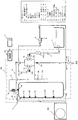
図4は、本実施の形態2に係る貯湯式給湯器のシステム構成図である。図4において、貯湯タンク1の最上部には、高温水を取り出す取り出し部41が設けられ、分岐部42より分岐して出湯管路31と膨張水排出管路33aとが設けられている。膨張水排出管路33aには、貯湯タンクから近い順に、混合弁23、圧力逃し弁20が設けられており、圧力逃し弁20及び混合弁23は、出湯管路31よりも高い場所に位置する。圧力逃し弁20の入口管は、混合弁23の出口側へ接続している。混合弁23は、一方の入口側を分岐部42から繋がる配管に、他方の入口側を給水管路32に接続している。なお、圧力逃し弁20の出口管に繋がる配管の端は、大気に開放されている。   FIG. 4 is a system configuration diagram of the hot water storage type hot water heater according to the second embodiment. In FIG. 4, at the uppermost part of the hot water storage tank 1, a take-out part 41 for taking out high-temperature water is provided, and a hot water discharge line 31 and an expanded water discharge line 33a are provided branched from the branch part 42. The expansion water discharge pipe 33 a is provided with a mixing valve 23 and a pressure relief valve 20 in order from the hot water storage tank, and the pressure relief valve 20 and the mixing valve 23 are positioned higher than the outlet hot water pipe 31. . The inlet pipe of the pressure relief valve 20 is connected to the outlet side of the mixing valve 23. The mixing valve 23 is connected to a pipe connecting one inlet side from the branch portion 42 and the other inlet side to the water supply pipe 32. The end of the pipe connected to the outlet pipe of the pressure relief valve 20 is open to the atmosphere.

貯湯タンク1内で沸き上げられた高温水は、取り出し部41を経て出湯管路31に導かれると同時に、分岐部42より分岐して混合弁23に流入する。また、給水管路32を流れる水も混合弁23に流入し、高温水と水は混合弁23により混合され、混合弁23の出口と圧力逃し弁20の入口との間に流入する。混合弁23において高温水と水とを混合する割合は、制御部10からの指令により弁開度を制御することによって調整する。このとき、高温水側の弁開度を小さくし、水側の弁開度を大きくして、圧力逃し弁20と混合弁23との間の配管内における低温水の割合を増やす。また、貯湯タンク1で発生したガスも高温水と同様に、貯湯タンク1を出て混合弁23を通過し、膨張水排出管路33a内の圧力逃し弁20の手前に滞留する。   The high-temperature water boiled in the hot water storage tank 1 is led to the hot water discharge pipe 31 through the take-out part 41 and is branched from the branch part 42 and flows into the mixing valve 23. Further, water flowing through the water supply pipe 32 also flows into the mixing valve 23, and high temperature water and water are mixed by the mixing valve 23 and flow between the outlet of the mixing valve 23 and the inlet of the pressure relief valve 20. The ratio of mixing high-temperature water and water in the mixing valve 23 is adjusted by controlling the valve opening degree according to a command from the control unit 10. At this time, the valve opening degree on the high temperature water side is decreased and the valve opening degree on the water side is increased to increase the ratio of the low temperature water in the pipe between the pressure relief valve 20 and the mixing valve 23. Similarly to the high-temperature water, the gas generated in the hot water storage tank 1 exits the hot water storage tank 1, passes through the mixing valve 23, and stays in front of the pressure relief valve 20 in the expansion water discharge pipe 33a.

以上の構成において、貯湯タンク1内の沸上げに伴う湯水の膨張により水回路内が圧力逃し弁20の開弁設定圧力に達すると、圧力逃し弁20が開弁し、膨張水及びガスが排出される。   In the above configuration, when the inside of the water circuit reaches the valve opening set pressure of the pressure relief valve 20 due to the expansion of the hot water accompanying boiling in the hot water storage tank 1, the pressure relief valve 20 is opened and the expansion water and gas are discharged. Is done.

したがって、湯水が温度上昇により膨張しても、貯湯タンク1及びこれに接続される配管回路内の内圧は、常に圧力逃し弁20の開弁設定圧力より小さく保つことができる。また、圧力逃し弁20の手前に滞留しているガスが優先的に排出されるため、水回路内にガスが残留することはない。   Therefore, even if the hot water expands due to a temperature rise, the internal pressure in the hot water storage tank 1 and the piping circuit connected to the hot water storage tank 1 can always be kept smaller than the valve opening set pressure of the pressure relief valve 20. Further, since the gas staying in front of the pressure relief valve 20 is discharged preferentially, no gas remains in the water circuit.

また、混合弁23は、高温水側の弁開度の方が小さく設定されているので、膨張水として排出される高温水の割合を小さくすることができる。   Moreover, since the valve opening degree of the high temperature water side is set smaller, the mixing valve 23 can make the ratio of the high temperature water discharged | emitted as expansion water small.

以上のように、本実施の形態2によると、貯湯タンク沸き上げ時に発生するガスを残留させることなく完全に排出することができるので、配管回路内にガスが滞留することによる不都合な現象を防ぐことが可能となる。
また、膨張水として排出するのは低温水が多く高温水は少ないため、膨張水排出による貯湯エネルギーのロスを最小限に抑えることができ、給湯システムの効率向上に貢献することができる。
As described above, according to the second embodiment, the gas generated when boiling the hot water storage tank can be completely discharged without remaining, thereby preventing an inconvenient phenomenon due to the gas remaining in the piping circuit. It becomes possible.
Moreover, since low temperature water is discharged as expansion water and high temperature water is small, loss of hot water storage energy due to discharge of expansion water can be minimized, which can contribute to improving the efficiency of the hot water supply system.

また、本実施の形態2によれば、圧力逃し機構を構成する膨張水排出管路33aと、混合弁2a、2bに繋がる出湯管路31とは完全に独立しており、混合弁2a、2bは圧力逃し弁20による膨張水処理動作とは完全に独立して制御することが可能である。そのため、膨張水排出中であるか否かに拘わらず、混合弁2a、2bの開度は常に給湯温度に適した開度に保たれている。したがって、たとえ停電が発生して混合弁2a、2bの制御ができない状態で使用者が蛇口などから給湯を開始したとしても、高温の湯水やガスが吹き出すおそれはない。また、混合弁2a、2bは膨張水排出目的で制御されることはないので、給湯開始時における目標温度までの安定速度も速い。   Further, according to the second embodiment, the expansion water discharge pipe 33a constituting the pressure relief mechanism and the tapping pipe 31 connected to the mixing valves 2a and 2b are completely independent, and the mixing valves 2a and 2b Can be controlled completely independently of the expansion water treatment operation by the pressure relief valve 20. Therefore, the opening degree of the mixing valves 2a and 2b is always kept at an opening degree suitable for the hot water supply temperature regardless of whether or not the expansion water is being discharged. Therefore, even if the user starts hot water supply from a faucet or the like in the state where a power failure occurs and the mixing valves 2a and 2b cannot be controlled, there is no possibility that hot hot water or gas will blow out. Further, since the mixing valves 2a and 2b are not controlled for the purpose of discharging the expanded water, the speed of stabilization up to the target temperature at the start of hot water supply is also fast.

なお、混合弁23の開度の別の制御方法として、貯湯タンク1の沸上げ終了前の時間帯に高温水側の弁開度を全開にし、これ以外のタイミングでは水側の弁開度を全開とすることもできる。沸上げ終了前の最もガスが発生している段階で高温水側の弁を全開にすることで、ガスを効率的に排出することができる。なお、弁開度の切り替えのタイミングは、例えば、温度センサ13a〜13eから得られる温度情報に基づいて計算される蓄熱量(残湯量)と、目標蓄熱量とを比較して行うことができる。具体例としては、目標蓄熱量に対し、95%まで達成した時点で高温水側の弁開度を全開とするよう制御してもよい。または、温度センサ13a〜13eのうちいずれかの温度が所定の温度に達したとき、高温水側の弁開度を全開とするよう制御してもよい。具体例としては、温度センサ13eの検出値が45℃に達したときに、高温水側の弁開度を全開とするよう制御するものがある。   As another method for controlling the opening of the mixing valve 23, the valve opening on the high temperature water side is fully opened in the time zone before the boiling of the hot water storage tank 1 is finished, and the valve opening on the water side is set at other timings. It can also be fully opened. The gas can be efficiently discharged by fully opening the valve on the high temperature water side at the stage where the most gas is generated before the completion of boiling. In addition, the timing of switching the valve opening can be performed by comparing, for example, a heat storage amount (remaining hot water amount) calculated based on temperature information obtained from the temperature sensors 13a to 13e and a target heat storage amount. As a specific example, the valve opening degree on the high temperature water side may be controlled to be fully opened when the target heat storage amount reaches 95%. Alternatively, when any one of the temperature sensors 13a to 13e reaches a predetermined temperature, the valve opening degree on the high temperature water side may be controlled to be fully opened. As a specific example, when the detected value of the temperature sensor 13e reaches 45 ° C., the valve opening degree on the high temperature water side is controlled to be fully opened.

また、実施の形態1と同様に、貯湯タンク1と混合弁23とを接続する配管の途中に、逆止弁を設けてもよい。逆止弁を設けることで、混合弁23の開度を中間開度に設定している場合においても、貯湯沸上げ運転時や出湯時に、低温水が貯湯タンク1に流れ込むのを防ぐことができる。   Moreover, you may provide a non-return valve in the middle of piping which connects the hot water storage tank 1 and the mixing valve 23 similarly to Embodiment 1. FIG. By providing a check valve, even when the opening of the mixing valve 23 is set to an intermediate opening, it is possible to prevent low-temperature water from flowing into the hot water storage tank 1 during hot water boiling operation or hot water. .

実施の形態3.
本実施の形態3では、圧力逃し弁20と分離膜24を用いて膨張水とガスとを排出する実施例について説明する。なお、膨張水排出に関する箇所以外については、前述の実施の形態1と同様であるので、同一符号を付して説明を省略する。
Embodiment 3 FIG.
In the third embodiment, an example in which expansion water and gas are discharged using the pressure relief valve 20 and the separation membrane 24 will be described. In addition, since it is the same as that of above-mentioned Embodiment 1 except the location regarding expansion water discharge, the same code | symbol is attached | subjected and description is abbreviate | omitted.

図5は、本実施の形態3に係る貯湯式給湯器のシステム構成図である。図5において、貯湯タンク1の最上部には、高温水を取り出す取り出し部41が設けられ、分岐部42より分岐して出湯管路31と分離膜24とが設けられており、分離膜24は、出湯管路31よりも高い場所に位置する。分離膜24には、ガス排出管路34が接続されており、分離膜24の出口管に繋がる配管の端は、大気に開放されている。   FIG. 5 is a system configuration diagram of a hot water storage type water heater according to the third embodiment. In FIG. 5, at the top of the hot water storage tank 1, a take-out part 41 for taking out high-temperature water is provided, branching from a branch part 42, a hot water discharge pipe 31 and a separation membrane 24 are provided. It is located in a place higher than the outlet hot water pipe 31. A gas exhaust pipe 34 is connected to the separation membrane 24, and the end of the pipe connected to the outlet pipe of the separation membrane 24 is open to the atmosphere.

分離膜24は、水と空気を分離する膜である。空気分子は通過できるが水分子は通過できないような孔径の膜であり、例えば、中空糸膜などである。分離膜24は、入口側(水側)が取り出し部41に繋がる配管に、出口側(空気側)がガス排出管路34aとなるよう設けられている。   The separation membrane 24 is a membrane that separates water and air. A membrane having a pore size that allows air molecules to pass but not water molecules, such as a hollow fiber membrane. The separation membrane 24 is provided so that the inlet side (water side) is connected to the take-out portion 41 and the outlet side (air side) is the gas discharge line 34a.

また、水源から繋がる配管に接続されて設けられた膨張水排出管路33bには、圧力逃し弁20が設けられている。圧力逃し弁20の出口管に繋がる端部は、大気に開放されている。   Moreover, the pressure relief valve 20 is provided in the expansion water discharge pipe 33b provided by being connected to the pipe connected from the water source. The end connected to the outlet pipe of the pressure relief valve 20 is open to the atmosphere.

以上の構成において、通常時、分離膜24へは、取り出し部41から繋がる配管により、貯湯タンク1内の水圧が加えられている状態である。
ここで、貯湯タンク1の沸上げに伴ってガスが発生すると、貯湯タンク1の最上部に設けられた取り出し部41を通過し、出湯管路31よりも高い位置にある分離膜24の近傍にガスが集まる。集まったガスは、貯湯タンク1内の水圧により分離膜24を通過し、ガス排出管路34を経て大気中へ排出される。分離膜24はガスのみを通過させるので、高温水が排出されることはない。
In the above configuration, normally, the water pressure in the hot water storage tank 1 is applied to the separation membrane 24 by a pipe connected from the take-out portion 41.
Here, when gas is generated with the boiling of the hot water storage tank 1, it passes through the take-out portion 41 provided at the uppermost part of the hot water storage tank 1, and in the vicinity of the separation membrane 24 at a position higher than the hot water discharge pipe 31. Gas gathers. The collected gas passes through the separation membrane 24 due to the water pressure in the hot water storage tank 1, and is discharged to the atmosphere via the gas discharge pipe 34. Since only the gas passes through the separation membrane 24, high temperature water is not discharged.

また、貯湯タンク1の沸上げに伴って水回路内の圧力が上昇し、圧力逃し弁20の開弁設定圧力に達すると、圧力逃し弁20が開弁して膨張水として低温水が排出される。圧力逃し弁20は、高温水が流れる配管とは接続されていないため、高温水を膨張水として排出することはない。   Further, when the pressure in the water circuit rises with the boiling of the hot water storage tank 1 and reaches the valve opening set pressure of the pressure relief valve 20, the pressure relief valve 20 opens and low temperature water is discharged as expansion water. The Since the pressure relief valve 20 is not connected to the pipe through which the high temperature water flows, the high temperature water is not discharged as expansion water.

したがって、湯水が温度上昇により膨張しても、貯湯タンク1及びこれに接続される配管回路内の内圧は、常に圧力逃し弁20の開弁設定圧力より小さく保つことができる。また、貯湯タンク1の最上部に設けられた取り出し部41に接続して分離膜24を設けたため、分離膜24を通して貯湯タンク1内のガスが排出され、水回路内にガスが残留することはない。   Therefore, even if the hot water expands due to a temperature rise, the internal pressure in the hot water storage tank 1 and the piping circuit connected to the hot water storage tank 1 can always be kept smaller than the valve opening set pressure of the pressure relief valve 20. Further, since the separation membrane 24 is provided in connection with the take-out portion 41 provided at the uppermost portion of the hot water storage tank 1, the gas in the hot water storage tank 1 is discharged through the separation membrane 24, and the gas remains in the water circuit. Absent.

以上のように、本実施の形態3によると、ガスのみを選択的に排出する分離膜24を貯湯タンク1の最上部に接続された配管上に設けたので、水回路内からすべてのガスを排出することができる。また、低温水が流れる配管に圧力逃し弁20を接続したので、膨張水として高温水を排出することがなく、膨張水排出に伴う貯湯エネルギーのロスがない。したがって、給湯システムの効率向上に貢献することができる。   As described above, according to the third embodiment, since the separation membrane 24 that selectively discharges only the gas is provided on the pipe connected to the uppermost part of the hot water storage tank 1, all the gas is discharged from the water circuit. Can be discharged. Further, since the pressure relief valve 20 is connected to the pipe through which the low temperature water flows, the high temperature water is not discharged as the expansion water, and there is no loss of hot water storage energy due to the discharge of the expansion water. Therefore, it can contribute to the efficiency improvement of the hot water supply system.

また、本実施の形態3によれば、圧力逃し機構を構成するガス排出管路34及び膨張水排出管路33bと、混合弁2a、2bに繋がる出湯管路31とは完全に独立している。このため、混合弁2a、2bは、ガス及び膨張水処理動作とは完全に独立して制御することが可能である。したがって、膨張水排出中であるか否かに拘わらず、混合弁2a、2bの開度は常に給湯温度に適した開度に保たれている。したがって、たとえ停電が発生して混合弁2a、2bの制御ができない状態で使用者が蛇口などから給湯を開始したとしても、高温の湯水やガスが吹き出すおそれはない。また、混合弁2a、2bは膨張水排出目的で制御されることはないので、給湯開始時における目標温度までの安定速度も速い。   Further, according to the third embodiment, the gas discharge pipe 34 and the expansion water discharge pipe 33b constituting the pressure relief mechanism and the tap water pipe 31 connected to the mixing valves 2a and 2b are completely independent. . For this reason, the mixing valves 2a and 2b can be controlled completely independently of the gas and expanded water treatment operations. Therefore, the opening degree of the mixing valves 2a and 2b is always kept at an opening degree suitable for the hot water supply temperature regardless of whether or not the expansion water is being discharged. Therefore, even if the user starts hot water supply from a faucet or the like in the state where a power failure occurs and the mixing valves 2a and 2b cannot be controlled, there is no possibility that hot hot water or gas will blow out. Further, since the mixing valves 2a and 2b are not controlled for the purpose of discharging the expanded water, the speed of stabilization up to the target temperature at the start of hot water supply is also fast.

実施の形態4.
本実施の形態4では、圧力逃し弁20とフロート弁25を用いて膨張水とガスとを排出する実施例について説明する。なお、膨張水排出機構に関する部分以外は前述の実施の形態1と同様であるので、同一符号を付して説明を省略する。
Embodiment 4 FIG.
In the fourth embodiment, an example in which expansion water and gas are discharged using the pressure relief valve 20 and the float valve 25 will be described. In addition, since it is the same as that of the above-mentioned Embodiment 1 except the part regarding an expanded water discharge mechanism, the same code | symbol is attached | subjected and description is abbreviate | omitted.

図6は、本実施の形態4に係る貯湯式給湯器のシステム構成図である。図6において、貯湯タンク1の最上部には、高温水を取り出す取り出し部41が設けられ、分岐部42より分岐して出湯管路31とフロート弁25とが設けられており、フロート弁25は、出湯管路31よりも高い場所に位置する。フロート弁25には、ガス排出管路34aが接続されており、フロート弁25の出口管に繋がる配管の端は、大気に開放されている。   FIG. 6 is a system configuration diagram of a hot water storage type water heater according to the fourth embodiment. In FIG. 6, at the top of the hot water storage tank 1, a take-out part 41 for taking out high-temperature water is provided, a hot water pipe 31 and a float valve 25 are provided by branching from a branch part 42, and the float valve 25 is It is located in a place higher than the outlet hot water pipe 31. A gas discharge pipe 34a is connected to the float valve 25, and the end of the pipe connected to the outlet pipe of the float valve 25 is open to the atmosphere.

フロート弁25は、入口流路が取り出し部41に繋がる配管に、出口流路がガス排出管路34aとなるように設けられている。
フロート弁25の内部には、水より軽く水に浮くフロート25aが内蔵されている。フロート弁25は、内部が水で満たされると、フロート25aがフロート弁25内部の上壁に水回路内圧により押しつけられる。フロート25aがフロート弁25内部上壁に押しつけられるとフロート弁25の出口流路を塞ぐので、水が外部へ流出しない。すなわち、フロート弁25の出口流路からは、水が流出しない構造となっている。
The float valve 25 is provided in a pipe where the inlet flow path is connected to the take-out portion 41 so that the outlet flow path is the gas discharge pipe 34a.
A float 25 a that floats in water lighter than water is built in the float valve 25. When the inside of the float valve 25 is filled with water, the float 25a is pressed against the upper wall inside the float valve 25 by water circuit internal pressure. When the float 25a is pressed against the upper wall inside the float valve 25, the outlet flow path of the float valve 25 is closed, so that water does not flow out. That is, the structure is such that water does not flow out from the outlet channel of the float valve 25.

また、水源から繋がる配管に接続されて設けられた膨張水排出管路33cには、圧力逃し弁20が設けられている。圧力逃し弁20の出口管に繋がる端部は、大気に開放されている。   Moreover, the pressure relief valve 20 is provided in the expansion water discharge pipe 33c provided by being connected to the pipe connected from the water source. The end connected to the outlet pipe of the pressure relief valve 20 is open to the atmosphere.

以上の構成において、フロート弁25内にガスが流入した場合には、フロート25aが水に浮き、フロート弁25内部の上部空間がガスで満たされ、フロート25aとフロート弁25内部の上部に設けられた出口部との間隔が広くなってガスが排出される。そして、フロート弁25内のガスがすべて排出されると再びフロート25aが上昇して出口流路が塞がれる。ガスが排出された時点で出口流路が塞がれるので、高温水を排出することはない。   In the above configuration, when the gas flows into the float valve 25, the float 25a floats on the water, the upper space inside the float valve 25 is filled with the gas, and the float 25a and the float valve 25 are provided in the upper part. The gap with the outlet becomes wider and the gas is discharged. And when all the gas in the float valve 25 is discharged | emitted, the float 25a will raise again and the outlet flow path will be block | closed. Since the outlet channel is closed when the gas is discharged, the high temperature water is not discharged.

また、貯湯タンク1の沸上げに伴って水回路内の圧力が上昇し、圧力逃し弁20の開弁設定圧力に達すると、圧力逃し弁20が開弁して膨張水として低温水が排出される。圧力逃し弁20は、高温水が流れる配管とは接続されていないため、高温水を膨張水として排出することはない。   Further, when the pressure in the water circuit rises with the boiling of the hot water storage tank 1 and reaches the valve opening set pressure of the pressure relief valve 20, the pressure relief valve 20 opens and low temperature water is discharged as expansion water. The Since the pressure relief valve 20 is not connected to the pipe through which the high temperature water flows, the high temperature water is not discharged as expansion water.

したがって、湯水が温度上昇により膨張しても、貯湯タンク1及びこれに接続される配管回路内の内圧は、常に圧力逃し弁20の開弁設定圧力より小さく保つことができる。また、貯湯タンク1の最上部に設けられた取り出し部41に接続してフロート弁25を設けたため、フロート弁25を通して貯湯タンク1内のガスが排出され、水回路内にガスが残留することはない。   Therefore, even if the hot water expands due to a temperature rise, the internal pressure in the hot water storage tank 1 and the piping circuit connected to the hot water storage tank 1 can always be kept smaller than the valve opening set pressure of the pressure relief valve 20. Further, since the float valve 25 is provided by connecting to the take-out portion 41 provided at the uppermost part of the hot water storage tank 1, the gas in the hot water storage tank 1 is discharged through the float valve 25, and the gas remains in the water circuit. Absent.

以上のように、本実施の形態4によると、ガスのみを選択的に排出するフロート弁25を貯湯タンク1の最上部に接続された配管上に備えたので、水回路内からすべてのガスを排出することができる。また、低温水が流れる配管に圧力逃し弁20を接続したので、膨張水として高温水を排出することがなく、膨張水排出に伴う貯湯エネルギーのロスがない。したがって、給湯システムの効率向上に貢献することができる。   As described above, according to the fourth embodiment, the float valve 25 for selectively discharging only the gas is provided on the pipe connected to the uppermost part of the hot water storage tank 1, so that all the gas is discharged from the water circuit. Can be discharged. Further, since the pressure relief valve 20 is connected to the pipe through which the low temperature water flows, the high temperature water is not discharged as the expansion water, and there is no loss of hot water storage energy due to the discharge of the expansion water. Therefore, it can contribute to the efficiency improvement of the hot water supply system.

また、本実施の形態4によれば、圧力逃し機構を構成するガス排出管路34a及び膨張水排出管路33cと、混合弁2a、2bに繋がる出湯管路31とは完全に独立している。このため、混合弁2a、2bは、ガス及び膨張水処理動作とは完全に独立して制御することが可能である。したがって、膨張水排出中であるか否かに拘わらず、混合弁2a、2bの開度は常に給湯温度に適した開度に保たれている。したがって、たとえ停電が発生して混合弁2a、2bの制御ができない状態で給湯を開始したとしても、高温の湯水やガスが吹き出すおそれはない。また、混合弁2a、2bは膨張水排出目的で制御されることはないので、給湯開始時における目標温度までの安定速度も速い。   Further, according to the fourth embodiment, the gas discharge pipe 34a and the expansion water discharge pipe 33c constituting the pressure relief mechanism and the tap water pipe 31 connected to the mixing valves 2a and 2b are completely independent. . For this reason, the mixing valves 2a and 2b can be controlled completely independently of the gas and expanded water treatment operations. Therefore, the opening degree of the mixing valves 2a and 2b is always kept at an opening degree suitable for the hot water supply temperature regardless of whether or not the expansion water is being discharged. Therefore, even if hot water supply is started in the state where the power failure occurs and the mixing valves 2a and 2b cannot be controlled, there is no possibility that hot hot water or gas will blow out. Further, since the mixing valves 2a and 2b are not controlled for the purpose of discharging the expanded water, the speed of stabilization up to the target temperature at the start of hot water supply is also fast.

1 貯湯タンク、2a 一般給湯側混合弁、2b 風呂給湯側混合弁、3 減圧弁、4 電磁弁、5 浴槽、6 混合栓、7 リモコン、10 制御部、11a、11b 流量センサ、12a、12b、12c、12d 温度センサ、13a、13b、13c、13d、13e 温度センサ、20 圧力逃し弁、21 オリフィス、22 逆止弁、23 混合弁、24 分離膜、25 フロート弁、25a フロート、31 出湯管路、32 給水管路、33、33a、33b、33c 膨張水排出管路、34、34a ガス排出管路、41 取り出し部、42、43 分岐部、100 貯湯ユニット、200 熱源ユニット。   DESCRIPTION OF SYMBOLS 1 Hot water storage tank, 2a General hot water supply side mixing valve, 2b Bath hot water supply side mixing valve, 3 Pressure reducing valve, 4 Solenoid valve, 5 Bathtub, 6 Mixing plug, 7 Remote control, 10 Control part, 11a, 11b Flow sensor, 12a, 12b, 12c, 12d temperature sensor, 13a, 13b, 13c, 13d, 13e temperature sensor, 20 pressure relief valve, 21 orifice, 22 check valve, 23 mixing valve, 24 separation membrane, 25 float valve, 25a float, 31 outlet pipe , 32 Water supply line, 33, 33a, 33b, 33c Expansion water discharge line, 34, 34a Gas discharge line, 41 Extraction part, 42, 43 Branch part, 100 Hot water storage unit, 200 Heat source unit.

Claims (2)

湯水を貯留する貯湯タンクと、
前記貯湯タンクに給水する給水管と、
前記貯湯タンクに貯留された高温水を出湯する出湯管と
を有する貯湯式給湯器において、
前記出湯管からの高温水と前記給水管からの水とを混合する給湯用混合弁と、
前記給水管の前記給湯用混合弁よりも上流側に設けられた圧力逃し弁と、
前記貯湯タンクの最上部に接続された配管もしくは高温水が流れる高温側配管に設けられた水と空気を分離する分離膜とを有し、
前記圧力逃し弁から膨張水を排出し、前記分離膜から気体を排出する
ことを特徴とする貯湯式給湯器。
A hot water storage tank for storing hot water,
A water supply pipe for supplying water to the hot water storage tank;
A hot water storage water heater having a hot water discharge pipe for discharging hot water stored in the hot water storage tank;
A hot water supply mixing valve for mixing hot water from the hot water pipe and water from the water supply pipe;
A pressure relief valve provided upstream of the hot water supply mixing valve of the water supply pipe;
A separation membrane that separates air and water provided in a pipe connected to the top of the hot water storage tank or a high temperature side pipe through which high temperature water flows;
A hot water storage type hot water heater characterized in that expansion water is discharged from the pressure relief valve and gas is discharged from the separation membrane.
湯水を貯留する貯湯タンクと、
前記貯湯タンクに給水する給水管と、
前記貯湯タンクに貯留された高温水を出湯する出湯管と
を有する貯湯式給湯器において、
前記出湯管からの高温水と前記給水管からの水とを混合する給湯用混合弁と、
前記給水管の前記給湯用混合弁よりも上流側に設けられた圧力逃し弁と、
前記貯湯タンクの最上部に接続された配管もしくは高温水が流れる高温側配管に設けられたフロート弁とを有し、
前記圧力逃し弁から膨張水を排出し、前記フロート弁から気体を排出する
ことを特徴とする貯湯式給湯器。
A hot water storage tank for storing hot water,
A water supply pipe for supplying water to the hot water storage tank;
A hot water storage water heater having a hot water discharge pipe for discharging hot water stored in the hot water storage tank;
A hot water supply mixing valve for mixing hot water from the hot water pipe and water from the water supply pipe;
A pressure relief valve provided upstream of the hot water supply mixing valve of the water supply pipe;
A pipe connected to the top of the hot water storage tank or a float valve provided on a high temperature side pipe through which high temperature water flows,
A hot water storage type hot water heater, characterized in that expansion water is discharged from the pressure relief valve and gas is discharged from the float valve.
JP2011274756A 2011-12-15 2011-12-15 Hot water storage water heater Active JP5361981B2 (en)

Priority Applications (1)

Application Number Priority Date Filing Date Title
JP2011274756A JP5361981B2 (en) 2011-12-15 2011-12-15 Hot water storage water heater

Applications Claiming Priority (1)

Application Number Priority Date Filing Date Title
JP2011274756A JP5361981B2 (en) 2011-12-15 2011-12-15 Hot water storage water heater

Related Parent Applications (1)

Application Number Title Priority Date Filing Date
JP2008092595A Division JP4986911B2 (en) 2008-03-31 2008-03-31 Hot water storage water heater

Publications (2)

Publication Number Publication Date
JP2012052803A JP2012052803A (en) 2012-03-15
JP5361981B2 true JP5361981B2 (en) 2013-12-04

Family

ID=45906304

Family Applications (1)

Application Number Title Priority Date Filing Date
JP2011274756A Active JP5361981B2 (en) 2011-12-15 2011-12-15 Hot water storage water heater

Country Status (1)

Country Link
JP (1) JP5361981B2 (en)

Families Citing this family (2)

* Cited by examiner, † Cited by third party
Publication number Priority date Publication date Assignee Title
JP5859419B2 (en) * 2012-11-29 2016-02-10 日立アプライアンス株式会社 Water heater
JP6551262B2 (en) * 2016-03-02 2019-07-31 株式会社デンソー Water heater

Family Cites Families (6)

* Cited by examiner, † Cited by third party
Publication number Priority date Publication date Assignee Title
JPS534342U (en) * 1976-06-29 1978-01-14
JPH0163882U (en) * 1987-10-16 1989-04-24
JPH01234695A (en) * 1988-03-14 1989-09-19 Tlv Co Ltd Discharge valve using separating membrane
JP2897564B2 (en) * 1992-12-02 1999-05-31 松下電器産業株式会社 Water supply / drainage device for hot water storage type water heater
JPH06313566A (en) * 1993-04-28 1994-11-08 Nepon Kk Air separator for water hammer prevention
JP4502785B2 (en) * 2004-11-16 2010-07-14 三洋電機株式会社 Hot water heater

Also Published As

Publication number Publication date
JP2012052803A (en) 2012-03-15

Similar Documents

Publication Publication Date Title
JP4986911B2 (en) Hot water storage water heater
JP2015001324A (en) Storage type water heater
JP2006308233A (en) Hot water supply apparatus
JP5361981B2 (en) Hot water storage water heater
JP5401116B2 (en) Water heater
JP5401117B2 (en) Water heater
JP5836794B2 (en) Hot water storage system
JP5458967B2 (en) Hot water storage water heater
JP2009002599A (en) Heat pump type water heater
JP6080731B2 (en) Water heater
JP2018099424A (en) Bath device
JP2007292346A (en) Hot water storage type water heater
JP2013133991A (en) Hot water storage system
JP6286312B2 (en) Hot water storage system
JP2006010172A (en) Hot water storage type hot water supply system
JP2009250542A (en) Water heater
JP2015031456A (en) Hot water supply device
JP6312565B2 (en) Hot water storage water heater with bubble function
JP2009074797A (en) Heat pump water heater
JP2009109188A (en) Heat pump water heater
JP2007292345A (en) Hot water storage type water heater
JP2010014316A (en) Hot water supply system
JP2009047374A (en) Hot-water supply device
JP6207411B2 (en) Hot water storage water heater
JP2005315523A (en) Hot-water supply device

Legal Events

Date Code Title Description
A621 Written request for application examination

Free format text: JAPANESE INTERMEDIATE CODE: A621

Effective date: 20111215

A131 Notification of reasons for refusal

Free format text: JAPANESE INTERMEDIATE CODE: A131

Effective date: 20130312

A521 Request for written amendment filed

Free format text: JAPANESE INTERMEDIATE CODE: A523

Effective date: 20130423

TRDD Decision of grant or rejection written
A01 Written decision to grant a patent or to grant a registration (utility model)

Free format text: JAPANESE INTERMEDIATE CODE: A01

Effective date: 20130806

A61 First payment of annual fees (during grant procedure)

Free format text: JAPANESE INTERMEDIATE CODE: A61

Effective date: 20130903

R150 Certificate of patent or registration of utility model

Ref document number: 5361981

Country of ref document: JP

Free format text: JAPANESE INTERMEDIATE CODE: R150

Free format text: JAPANESE INTERMEDIATE CODE: R150

R250 Receipt of annual fees

Free format text: JAPANESE INTERMEDIATE CODE: R250

R250 Receipt of annual fees

Free format text: JAPANESE INTERMEDIATE CODE: R250

R250 Receipt of annual fees

Free format text: JAPANESE INTERMEDIATE CODE: R250

R250 Receipt of annual fees

Free format text: JAPANESE INTERMEDIATE CODE: R250

R250 Receipt of annual fees

Free format text: JAPANESE INTERMEDIATE CODE: R250

R250 Receipt of annual fees

Free format text: JAPANESE INTERMEDIATE CODE: R250

R250 Receipt of annual fees

Free format text: JAPANESE INTERMEDIATE CODE: R250

R250 Receipt of annual fees

Free format text: JAPANESE INTERMEDIATE CODE: R250