JP5359657B2 - Image encoding apparatus and method, recording medium, and program - Google Patents
Image encoding apparatus and method, recording medium, and program Download PDFInfo
- Publication number
- JP5359657B2 JP5359657B2 JP2009179394A JP2009179394A JP5359657B2 JP 5359657 B2 JP5359657 B2 JP 5359657B2 JP 2009179394 A JP2009179394 A JP 2009179394A JP 2009179394 A JP2009179394 A JP 2009179394A JP 5359657 B2 JP5359657 B2 JP 5359657B2
- Authority
- JP
- Japan
- Prior art keywords
- image
- unit
- data
- block
- adaptive filter
- Prior art date
- Legal status (The legal status is an assumption and is not a legal conclusion. Google has not performed a legal analysis and makes no representation as to the accuracy of the status listed.)
- Active
Links
Images


Classifications
-
- H—ELECTRICITY
- H04—ELECTRIC COMMUNICATION TECHNIQUE
- H04N—PICTORIAL COMMUNICATION, e.g. TELEVISION
- H04N19/00—Methods or arrangements for coding, decoding, compressing or decompressing digital video signals
- H04N19/10—Methods or arrangements for coding, decoding, compressing or decompressing digital video signals using adaptive coding
- H04N19/102—Methods or arrangements for coding, decoding, compressing or decompressing digital video signals using adaptive coding characterised by the element, parameter or selection affected or controlled by the adaptive coding
- H04N19/117—Filters, e.g. for pre-processing or post-processing
-
- H—ELECTRICITY
- H04—ELECTRIC COMMUNICATION TECHNIQUE
- H04N—PICTORIAL COMMUNICATION, e.g. TELEVISION
- H04N19/00—Methods or arrangements for coding, decoding, compressing or decompressing digital video signals
- H04N19/10—Methods or arrangements for coding, decoding, compressing or decompressing digital video signals using adaptive coding
- H04N19/134—Methods or arrangements for coding, decoding, compressing or decompressing digital video signals using adaptive coding characterised by the element, parameter or criterion affecting or controlling the adaptive coding
- H04N19/154—Measured or subjectively estimated visual quality after decoding, e.g. measurement of distortion
-
- H—ELECTRICITY
- H04—ELECTRIC COMMUNICATION TECHNIQUE
- H04N—PICTORIAL COMMUNICATION, e.g. TELEVISION
- H04N19/00—Methods or arrangements for coding, decoding, compressing or decompressing digital video signals
- H04N19/10—Methods or arrangements for coding, decoding, compressing or decompressing digital video signals using adaptive coding
- H04N19/169—Methods or arrangements for coding, decoding, compressing or decompressing digital video signals using adaptive coding characterised by the coding unit, i.e. the structural portion or semantic portion of the video signal being the object or the subject of the adaptive coding
- H04N19/17—Methods or arrangements for coding, decoding, compressing or decompressing digital video signals using adaptive coding characterised by the coding unit, i.e. the structural portion or semantic portion of the video signal being the object or the subject of the adaptive coding the unit being an image region, e.g. an object
- H04N19/172—Methods or arrangements for coding, decoding, compressing or decompressing digital video signals using adaptive coding characterised by the coding unit, i.e. the structural portion or semantic portion of the video signal being the object or the subject of the adaptive coding the unit being an image region, e.g. an object the region being a picture, frame or field
-
- H—ELECTRICITY
- H04—ELECTRIC COMMUNICATION TECHNIQUE
- H04N—PICTORIAL COMMUNICATION, e.g. TELEVISION
- H04N19/00—Methods or arrangements for coding, decoding, compressing or decompressing digital video signals
- H04N19/10—Methods or arrangements for coding, decoding, compressing or decompressing digital video signals using adaptive coding
- H04N19/189—Methods or arrangements for coding, decoding, compressing or decompressing digital video signals using adaptive coding characterised by the adaptation method, adaptation tool or adaptation type used for the adaptive coding
- H04N19/196—Methods or arrangements for coding, decoding, compressing or decompressing digital video signals using adaptive coding characterised by the adaptation method, adaptation tool or adaptation type used for the adaptive coding being specially adapted for the computation of encoding parameters, e.g. by averaging previously computed encoding parameters
-
- H—ELECTRICITY
- H04—ELECTRIC COMMUNICATION TECHNIQUE
- H04N—PICTORIAL COMMUNICATION, e.g. TELEVISION
- H04N19/00—Methods or arrangements for coding, decoding, compressing or decompressing digital video signals
- H04N19/46—Embedding additional information in the video signal during the compression process
- H04N19/463—Embedding additional information in the video signal during the compression process by compressing encoding parameters before transmission
-
- H—ELECTRICITY
- H04—ELECTRIC COMMUNICATION TECHNIQUE
- H04N—PICTORIAL COMMUNICATION, e.g. TELEVISION
- H04N19/00—Methods or arrangements for coding, decoding, compressing or decompressing digital video signals
- H04N19/50—Methods or arrangements for coding, decoding, compressing or decompressing digital video signals using predictive coding
- H04N19/593—Methods or arrangements for coding, decoding, compressing or decompressing digital video signals using predictive coding involving spatial prediction techniques
-
- H—ELECTRICITY
- H04—ELECTRIC COMMUNICATION TECHNIQUE
- H04N—PICTORIAL COMMUNICATION, e.g. TELEVISION
- H04N19/00—Methods or arrangements for coding, decoding, compressing or decompressing digital video signals
- H04N19/80—Details of filtering operations specially adapted for video compression, e.g. for pixel interpolation
- H04N19/82—Details of filtering operations specially adapted for video compression, e.g. for pixel interpolation involving filtering within a prediction loop
Landscapes
- Engineering & Computer Science (AREA)
- Multimedia (AREA)
- Signal Processing (AREA)
- Computing Systems (AREA)
- Theoretical Computer Science (AREA)
- Compression Or Coding Systems Of Tv Signals (AREA)
Abstract
Description
本発明は、画像符号化装置および方法、記録媒体、並びにプログラムに関し、特に、符号化時または復号時のフィルタ処理の局所的な制御による符号化効率の低減を抑制することができるようにした画像符号化装置および方法、記録媒体、並びにプログラムに関する。 The present invention relates to an image encoding apparatus and method, a recording medium, and a program , and more particularly to an image that can suppress a reduction in encoding efficiency due to local control of filter processing during encoding or decoding. The present invention relates to an encoding apparatus and method, a recording medium, and a program .
近年、画像情報をデジタルとして取り扱い、その際、効率の高い情報の伝送、蓄積を目的とし、画像情報特有の冗長性を利用して、離散コサイン変換等の直交変換と動き補償により圧縮するMPEG(Moving Picture Experts Group)などの方式に準拠した装置が、放送局などの情報配信、及び一般家庭における情報受信の双方において普及しつつある。 In recent years, image information is handled as digital data, and MPEG (compressed by orthogonal transform such as discrete cosine transform and motion compensation is used for the purpose of efficient transmission and storage of information. A device conforming to a system such as Moving Picture Experts Group) is becoming popular in both information distribution at broadcasting stations and information reception in general households.
特に、MPEG2(ISO(International Organization for Standardization)/IEC(International Electrotechnical Commission)13818-2)は、汎用画像符号化方式として定義されており、飛び越し走査画像及び順次走査画像の双方、並びに標準解像度画像及び高精細画像を網羅する標準で、プロフェッショナル用途及びコンシューマ用途の広範なアプリケーションに現在広く用いられている。MPEG2圧縮方式を用いることにより、例えば720×480画素を持つ標準解像度の飛び越し走査画像であれば4〜8Mbps、1920×1088画素を持つ高解像度の飛び越し走査画像であれば18〜22Mbpsの符号量(ビットレート)を割り当てることで、高い圧縮率と良好な画質の実現が可能である。 In particular, MPEG2 (ISO (International Organization for Standardization) / IEC (International Electrotechnical Commission) 13818-2) is defined as a general-purpose image coding system, and includes both interlaced scanning images and progressive scanning images, as well as standard resolution images and This standard covers high-definition images and is currently widely used in a wide range of professional and consumer applications. By using the MPEG2 compression method, for example, a standard resolution interlaced scanning image having 720 × 480 pixels is 4 to 8 Mbps, and a high resolution interlaced scanning image having 1920 × 1088 pixels is 18 to 22 Mbps. (Bit rate) can be assigned to achieve a high compression rate and good image quality.
MPEG2は主として放送用に適合する高画質符号化を対象としていたが、MPEG1より低い符号量(ビットレート)、つまりより高い圧縮率の符号化方式には対応していなかった。携帯端末の普及により、今後そのような符号化方式のニーズは高まると思われ、これに対応してMPEG4符号化方式の標準化が行われた。画像符号化方式に関しては、1998年12月にISO/IEC14496-2としてその規格が国際標準に承認された。 MPEG2 was mainly intended for high-quality encoding suitable for broadcasting, but did not support encoding methods with a lower code amount (bit rate) than MPEG1, that is, a higher compression rate. With the widespread use of portable terminals, the need for such an encoding system is expected to increase in the future, and the MPEG4 encoding system has been standardized accordingly. Regarding the image coding system, the standard was approved as an international standard as ISO / IEC 14496-2 in December 1998.
更に、近年、当初テレビ会議用の画像符号化を目的として、H.26L(ITU-T(ITU Telecommunication Standardization Sector)Q6/16 VCEG(Video Coding Experts Group))という標準の規格化が進んでいる。H.26LはMPEG2やMPEG4といった従来の符号化方式に比べ、その符号化、復号化により多くの演算量が要求されるものの、より高い符号化効率が実現されることが知られている。また、現在、MPEG4の活動の一環として、このH.26Lをベースに、H.26Lではサポートされない機能をも取り入れ、より高い符号化効率を実現する標準化がJoint Model of Enhanced-Compression Video Codingとして行われている。標準化のスケジュールとしては、2003年3月にはH.264及びMPEG4 Part10(AVC(Advanced Video Coding))という名の元に国際標準となった。 Furthermore, in recent years, the standardization of a standard called H.26L (ITU-T (ITU Telecommunication Standardization Sector) Q6 / 16 VCEG (Video Coding Experts Group)) has been advanced for the purpose of image coding for an initial video conference. H.26L is known to achieve higher encoding efficiency than a conventional encoding method such as MPEG2 or MPEG4, although a large amount of calculation is required for encoding and decoding. Also, as part of MPEG4 activities, standardization to achieve higher coding efficiency based on this H.26L and incorporating functions not supported by H.26L has been carried out as Joint Model of Enhanced-Compression Video Coding. It has been broken. As a standardization schedule, in March 2003, it became an international standard under the names of H.264 and MPEG4 Part 10 (AVC (Advanced Video Coding)).
また、最近、検討されている次世代のビデオ符号化技術として適応ループフィルタ(ALF(Adaptive Loop Filter))がある(例えば、非特許文献1参照)。この適応フィルタにより、フレーム毎に最適なフィルタ処理が行われ、デブロックフィルタで取りきれなかったブロック歪みや量子化による歪みを低減することができる。 In addition, there is an adaptive loop filter (ALF (Adaptive Loop Filter)) as a next-generation video coding technique that has been recently examined (see, for example, Non-Patent Document 1). With this adaptive filter, optimal filter processing is performed for each frame, and block distortion that cannot be removed by the deblocking filter and distortion due to quantization can be reduced.
しかしながら、一般に画像は局所的には様々な特徴をもっているため、局所的には最適なフィルタ係数は異なる。非特許文献1記載の方法では、1フレーム内のすべて画素に対して同じフィルタ係数が適用されるため、フレーム全体では画質を改善するが、局所的には悪化させる恐れがあった。
However, since the image generally has various features locally, the optimum filter coefficient is different locally. In the method described in Non-Patent
そこで、局所的に悪化する領域にはフィルタ処理を行わない方法が考えられた(例えば非特許文献2、および非特許文献3参照)。この方法の場合、画像符号化装置は、画像の領域に、敷き詰めるように隙間無く並べられた複数の制御ブロックを対応させ、その制御ブロック毎に画像にフィルタ処理を行うか否かを制御する。画像符号化装置は、ブロック毎にフラグ情報を設定し、そのフラグ情報にしたがって適応フィルタ処理を行う。画像復号装置も同様に、このフラグ情報に基づいて適応フィルタ処理を行う。 In view of this, there has been considered a method in which the filtering process is not performed on a locally deteriorated region (for example, see Non-Patent Document 2 and Non-Patent Document 3). In the case of this method, the image encoding device associates a plurality of control blocks arranged without gaps so as to be spread over an image area, and controls whether or not to perform filter processing on the image for each control block. The image encoding apparatus sets flag information for each block, and performs adaptive filter processing according to the flag information. Similarly, the image decoding apparatus performs adaptive filter processing based on the flag information.
しかしながら、1フレームを複数のスライスに分割し、そのスライス毎に画像の符号化処理や復号処理を行う方法(マルチスライス)がある。非特許文献2および非特許文献3には、単に1フレーム全体についてブロックを設定し、全ブロックのフラグ情報を生成して送信することが記載されているのみであり、このようなマルチスライスの場合のフラグ情報の処理について記載されておらず、どのようにフラグ情報を生成し、利用するべきか不明であった。 However, there is a method (multi-slice) in which one frame is divided into a plurality of slices and an image encoding process or a decoding process is performed for each slice. Non-Patent Document 2 and Non-Patent Document 3 only describe that blocks are set for one entire frame, and flag information of all blocks is generated and transmitted. It was not described how to generate and use flag information.
非特許文献2および非特許文献3の記載によると、画像符号化装置は、フレーム内の1つのスライスに対して、フレーム内全てのブロックのフラグ情報を生成することしか記載されていない。つまり、マルチスライスの場合であっても、画像符号化装置は、各スライスに対して、フレーム内全てのブロックのフラグ情報を生成することになる。 According to the description of Non-Patent Document 2 and Non-Patent Document 3, the image coding apparatus is only described to generate flag information of all blocks in a frame for one slice in the frame. That is, even in the case of multi-slice, the image encoding device generates flag information of all blocks in the frame for each slice.
しかしながら、処理対象スライス以外の領域のブロックのフラグ情報は不要である。生成されたフラグ情報は画像データとともに符号化され画像圧縮情報に含められる。つまり、非特許文献2および非特許文献3に記載のような方法では、マルチスライスを適用する場合、画像圧縮情報を不要に増大させ符号化効率を悪化させる恐れがあった。 However, the flag information of blocks in areas other than the processing target slice is not necessary. The generated flag information is encoded together with the image data and included in the image compression information. That is, in the methods as described in Non-Patent Document 2 and Non-Patent Document 3, when multi-slice is applied, there is a possibility that image compression information is unnecessarily increased and coding efficiency is deteriorated.
本発明は、このような状況に鑑みて提案されたものであり、符号化時または復号時のフィルタ処理の局所的な制御による符号化効率の低減を抑制することを目的とする。 The present invention has been proposed in view of such a situation, and an object thereof is to suppress a reduction in encoding efficiency due to local control of filter processing at the time of encoding or decoding.
本発明の一側面は、画像データの処理対象のスライスに含まれるクアッドツリー構造の画素ブロック毎に適応フィルタ処理を行うかを制御する制御データと、前記適応フィルタ処理を行うクアッドツリー構造の画素ブロックのサイズを表すサイズデータとを生成する制御データ生成部と、前記制御データ生成部により生成された前記制御データにより処理対象の前記画素ブロックに対して前記適応フィルタ処理を行うように指示され、かつ前記サイズデータにより求められる位置における処理対象の前記画素ブロックの画素が処理対象の前記スライスに含まれる場合、処理対象の前記画素ブロックに対して前記適応フィルタ処理を行う適応フィルタ部と、前記適応フィルタ部により前記制御データに応じて適宜前記適応フィルタ処理が行われた画像データを用いて前記画像データを符号化する符号化部と、前記符号化部により生成された前記画像データの符号化データと、前記制御データと、前記サイズデータとを伝送する伝送部とを備える画像符号化装置である。 One aspect of the present invention provides control data for controlling whether to perform adaptive filter processing for each pixel block having a quad tree structure included in a slice to be processed of image data, and a quad block having a quad tree structure for performing the adaptive filter processing A control data generation unit that generates size data representing the size of the data, and the control data generated by the control data generation unit is instructed to perform the adaptive filter processing on the pixel block to be processed ; and An adaptive filter unit that performs the adaptive filter processing on the pixel block to be processed when the pixel of the pixel block to be processed at the position determined by the size data is included in the slice to be processed; and the adaptive filter The adaptive filter processing is appropriately performed by the unit according to the control data. An encoding unit for encoding the image data by using the image data, the encoded data of the image data generated by the encoding unit, and the control data, and a transmission unit for transmitting said size data An image encoding device provided.
本発明の一側面は、また、画像データの処理対象のスライスに含まれるクアッドツリー構造の画素ブロック毎に適応フィルタ処理を行うかを制御する制御データと、前記適応フィルタ処理を行うクアッドツリー構造の画素ブロックのサイズを表すサイズデータとを生成し、生成された前記制御データにより処理対象の前記画素ブロックに対して前記適応フィルタ処理を行うように指示され、かつ前記サイズデータにより求められる位置における処理対象の前記画素ブロックの画素が処理対象の前記スライスに含まれる場合、処理対象の前記画素ブロックに対して前記適応フィルタ処理を行い、前記制御データに応じて適宜前記適応フィルタ処理が行われた画像データを用いて前記画像データを符号化し、生成された前記画像データの符号化データと、前記制御データと、前記サイズデータとを伝送する画像符号化方法である。 One aspect of the present invention also includes control data for controlling whether to perform adaptive filter processing for each pixel block having a quad tree structure included in a slice to be processed of image data, and a quad tree structure for performing the adaptive filter processing. Size data representing the size of a pixel block, and processing at a position that is instructed to perform the adaptive filter processing on the pixel block to be processed by the generated control data and is obtained from the size data When the pixel of the target pixel block is included in the slice to be processed, the adaptive filter processing is performed on the pixel block to be processed, and the adaptive filter processing is appropriately performed according to the control data The image data is encoded using data, and the encoded data of the generated image data is encoded. A motor, and the control data is an image coding method for transmitting and the size data.
本発明の一側面は、さらに、コンピュータを、画像データの処理対象のスライスに含まれるクアッドツリー構造の画素ブロック毎に適応フィルタ処理を行うかを制御する制御データと、前記適応フィルタ処理を行うクアッドツリー構造の画素ブロックのサイズを表すサイズデータとを生成する制御データ生成部と、前記制御データ生成部により生成された前記制御データにより処理対象の前記画素ブロックに対して前記適応フィルタ処理を行うように指示され、かつ前記サイズデータにより求められる位置における処理対象の前記画素ブロックの画素が処理対象の前記スライスに含まれる場合、処理対象の前記画素ブロックに対して前記適応フィルタ処理を行う適応フィルタ部と、前記適応フィルタ部により前記制御データに応じて適宜前記適応フィルタ処理が行われた画像データを用いて前記画像データを符号化する符号化部と、前記符号化部により生成された前記画像データの符号化データと、前記制御データと、前記サイズデータとを伝送する伝送部として機能させるプログラムを記録したコンピュータが読み取り可能な記録媒体である。 One aspect of the present invention further includes control data for controlling whether the computer performs adaptive filter processing for each pixel block having a quad tree structure included in a slice to be processed of image data, and a quad for performing the adaptive filter processing. A control data generating unit that generates size data representing the size of a pixel block having a tree structure; and the adaptive filter processing is performed on the pixel block to be processed by the control data generated by the control data generating unit. When the pixel of the pixel block to be processed at the position determined by the size data is included in the slice to be processed, the adaptive filter unit that performs the adaptive filter processing on the pixel block to be processed And the adaptive filter unit appropriately according to the control data An encoding unit for encoding said image data using the image data adaptive filter processing is performed, encoded data of the image data generated by the encoding unit, and the control data, and the size data This is a computer-readable recording medium that records a program that functions as a transmission unit that transmits the program.
本発明の一側面は、また、コンピュータを、画像データの処理対象のスライスに含まれるクアッドツリー構造の画素ブロック毎に適応フィルタ処理を行うかを制御する制御データと、前記適応フィルタ処理を行うクアッドツリー構造の画素ブロックのサイズを表すサイズデータとを生成する制御データ生成部と、前記制御データ生成部により生成された前記制御データにより処理対象の前記画素ブロックに対して前記適応フィルタ処理を行うように指示され、かつ前記サイズデータにより求められる位置における処理対象の前記画素ブロックの画素が処理対象の前記スライスに含まれる場合、処理対象の前記画素ブロックに対して前記適応フィルタ処理を行う適応フィルタ部と、前記適応フィルタ部により前記制御データに応じて適宜前記適応フィルタ処理が行われた画像データを用いて前記画像データを符号化する符号化部と、前記符号化部により生成された前記画像データの符号化データと、前記制御データと、前記サイズデータとを伝送する伝送部として機能させるプログラムである。 One aspect of the present invention also provides control data for controlling whether the computer performs adaptive filter processing for each pixel block having a quad tree structure included in a slice to be processed of image data, and a quad for performing the adaptive filter processing. A control data generating unit that generates size data representing the size of a pixel block having a tree structure; and the adaptive filter processing is performed on the pixel block to be processed by the control data generated by the control data generating unit. When the pixel of the pixel block to be processed at the position determined by the size data is included in the slice to be processed, the adaptive filter unit that performs the adaptive filter processing on the pixel block to be processed And the adaptive filter unit according to the control data as appropriate. And encoding unit for filtering process to encode the image data using the image data is performed, encoded data of the image data generated by the encoding unit, and the control data, and the size data This is a program that functions as a transmission unit for transmission.
本発明の一側面においては、画像データの処理対象のスライスに含まれるクアッドツリー構造の画素ブロック毎に適応フィルタ処理を行うかを制御する制御データと、適応フィルタ処理を行うクアッドツリー構造の画素ブロックのサイズを表すサイズデータとが生成され、生成された制御データにより処理対象の画素ブロックに対して適応フィルタ処理を行うように指示され、かつサイズデータにより求められる位置における処理対象の画素ブロックの画素が処理対象のスライスに含まれる場合、処理対象の画素ブロックに対して適応フィルタ処理が行われ、制御データに応じて適宜適応フィルタ処理が行われた画像データを用いて画像データが符号化され、生成された画像データの符号化データと、制御データと、サイズデータとが伝送される。 In one aspect of the present invention, control data for controlling whether to perform adaptive filter processing for each pixel block having a quad tree structure included in a slice to be processed of image data, and a quad block having a quad tree structure for performing adaptive filter processing Size data representing the size of the pixel block, and the generated control data instructs the pixel block to be processed to perform adaptive filter processing , and the pixel of the pixel block to be processed at the position determined by the size data Is included in the slice to be processed, adaptive filter processing is performed on the pixel block to be processed, and image data is encoded using image data that has been appropriately subjected to adaptive filter processing according to control data, and the coded data of the generated image data, and control data, and the size data transmission That.
本発明によれば、画像を符号化することができる。特に、符号化時または復号時のフィルタ処理の局所的な制御による符号化効率の低減を抑制することができる。例えば、画像の各フレームを複数に分けて符号化または復号する場合においても、符号化効率の低減を抑制することができる。 According to the present invention, an image can be encoded . In particular, it is possible to suppress a reduction in encoding efficiency due to local control of filter processing during encoding or decoding. For example, even when each frame of an image is divided into a plurality of pieces for encoding or decoding, a reduction in encoding efficiency can be suppressed.
以下、発明を実施するための形態(以下実施の形態とする)について説明する。なお、説明は以下の順序で行う。
1.第1の実施の形態(画像符号化装置)
2.第2の実施の形態(画像復号装置)
3.第3の実施の形態(フィルタブロックフラグ生成処理の変形例)
4.第4の実施の形態(QALF)
5.第5の実施の形態(パーソナルコンピュータ)
6.第6の実施の形態(テレビジョン受像機)
7.第7の実施の形態(携帯電話機)
8.第8の実施の形態(ハードディスクレコーダ)
9.第9の実施の形態(カメラ)
Hereinafter, modes for carrying out the invention (hereinafter referred to as embodiments) will be described. The description will be given in the following order.
1. First Embodiment (Image Encoding Device)
2. Second embodiment (image decoding apparatus)
3. Third embodiment (variation of filter block flag generation processing)
4). Fourth embodiment (QALF)
5. Fifth embodiment (personal computer)
6). Sixth embodiment (television receiver)
7). Seventh embodiment (cellular phone)
8). Eighth embodiment (hard disk recorder)
9. Ninth embodiment (camera)
<1.第1の実施の形態>
[デバイスの構成]
図1は、本発明を適用した画像処理装置としての画像符号化装置の一実施の形態の構成を表している。
<1. First Embodiment>
[Device Configuration]
FIG. 1 shows a configuration of an embodiment of an image encoding apparatus as an image processing apparatus to which the present invention is applied.
図1に示される画像符号化装置100は、例えば、H.264及びMPEG4 Part10(Advanced Video Coding)(以下H.264/AVCと記す)方式で画像を圧縮符号化する符号化装置であり、さらに、適応ループフィルタを採用している。 An image encoding device 100 shown in FIG. It is an encoding device that compresses and encodes an image using an H.264 and MPEG4 Part 10 (Advanced Video Coding) (hereinafter referred to as H.264 / AVC) method, and further employs an adaptive loop filter.
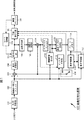
図1の例において、画像符号化装置100は、A/D(Analog / Digital)変換部101、画面並べ替えバッファ102、演算部103、直交変換部104、量子化部105、可逆符号化部106、および蓄積バッファ107を有する。また、画像符号化装置100は、逆量子化部108、逆直交変換部109、演算部110、およびデブロックフィルタ111を有する。さらに、画像符号化装置100は、制御情報生成部112、適応フィルタ処理部113、およびフレームメモリ114を有する。また、画像符号化装置100は、イントラ予測部115、動き補償部116、動き予測部117、および予測画像選択部118を有する。さらに、画像符号化装置100は、レート制御部119を有する。
In the example of FIG. 1, the image encoding device 100 includes an A / D (Analog / Digital)
A/D変換部101は、入力された画像をA/D変換し、画面並べ替えバッファ102に出力し、記憶させる。画面並べ替えバッファ102は、記憶した表示の順番のフレームの画像を、GOP(Group of Picture)構造に応じて、符号化のためのフレームの順番に並べ替える。
演算部103は、画面並べ替えバッファ102から読み出された画像から、予測画像選択部118により選択されたイントラ予測部115からの予測画像または動き補償部116からの予測画像を減算し、その差分情報を直交変換部104に出力する。直交変換部104は、演算部103からの差分情報に対して、離散コサイン変換、カルーネン・レーベ変換等の直交変換を施し、その変換係数を出力する。量子化部105は、直交変換部104が出力する変換係数を量子化する。
The A /
The
量子化部105の出力となる、量子化された変換係数は、可逆符号化部106に入力される。可逆符号化部106は、その量子化された変換係数に対して、可変長符号化、算術符号化等の可逆符号化を施し、圧縮する。
The quantized transform coefficient that is output from the
可逆符号化部106は、イントラ予測を示す情報などをイントラ予測部114から取得し、インター予測モードを示す情報などを動き予測部117から取得する。なお、イントラ予測を示す情報は、以下、イントラ予測モード情報とも称する。また、インター予測を示す情報モードを示す情報は、以下、インター予測モード情報とも称する。
The
可逆符号化部106は、さらに、適応フィルタ処理部113において行われる適応フィルタ処理の制御情報を、制御情報生成部112から取得する。
The
可逆符号化部106は、量子化された変換係数を符号化するとともに、適応フィルタ処理の制御情報、イントラ予測を示す情報やインター予測モードを示す情報、および量子化パラメータなどを符号化し、圧縮画像におけるヘッダ情報の一部とする(多重化する)。可逆符号化部106は、符号化したデータを蓄積バッファ107に供給して蓄積させる。
The
例えば、可逆符号化部106においては、可変長符号化または算術符号化等の可逆符号化処理が行われる。可変長符号化としては、H.264/AVC方式で定められているCAVLC(Context-Adaptive Variable Length Coding)などがあげられる。算術符号化としては、CABAC(Context-Adaptive Binary Arithmetic Coding)などがあげられる。
For example, the
蓄積バッファ107は、可逆符号化部106から供給されたデータを、一時的に保持し、所定のタイミングにおいて、H.264/AVC方式で符号化された圧縮画像として、例えば、後段の図示せぬ記録装置や伝送路などに出力する。
The
また、量子化部105において量子化された変換係数は、逆量子化部108にも入力される。逆量子化部108は、その量子化された変換係数を、量子化部105による量子化に対応する方法で逆量子化し、得られた変換係数を、逆直交変換部109に供給する。
Further, the transform coefficient quantized by the
逆直交変換部109は、供給された変換係数を、直交変換部104による直交変換処理に対応する方法で逆直交変換する。逆直交変換された出力は、演算部110に供給される。演算部110は、逆直交変換部109より供給された逆直交変換結果、すなわち、復元された差分情報に、予測画像選択部118から供給される予測画像を加算し、局部的に復号された画像(復号画像)を得る。その加算結果は、デブロックフィルタ111に供給される。
The inverse
デブロックフィルタ111は、復号画像のブロック歪を除去する。デブロックフィルタ111は、その歪除去結果を制御情報生成部112および適応フィルタ処理部113に供給する。
The
制御情報生成部112は、デブロックフィルタ111から供給される復号画像と、画面並べ替えバッファ102から読み出された現在の入力画像を取得し、それらから、適応フィルタ処理部113において行われる適応フィルタの制御情報を生成する。詳細については後述するが、制御情報には、フィルタ係数、ブロックサイズ、およびフィルタブロックフラグ等が含まれる。
The control
制御情報生成部112は、生成した制御情報を適応フィルタ処理部113に供給する。また、制御情報生成部112は、生成した制御情報を可逆符号化部106にも供給する。上述したように制御情報は、可逆符号化部106により、可逆圧縮処理され、画像圧縮情報に含められる(多重化する)。つまり、制御情報は、画像圧縮情報とともに画像復号装置に送られる。
The control
適応フィルタ処理部113は、制御情報生成部112から供給された制御情報のフィルタ係数、ブロックサイズ指定、およびフィルタブロックフラグ等を用いて、デブロックフィルタ111から供給される復号画像にフィルタ処理を行う。このフィルタとして、例えば、ウィナーフィルタ(Wiener Filter)が用いられる。もちろんウィナーフィルタ以外のフィルタを用いても良い。適応フィルタ処理部113は、フィルタ処理結果をフレームメモリ114に供給し、参照画像として蓄積させる。
The adaptive
フレームメモリ114は、所定のタイミングにおいて、蓄積されている参照画像を動き補償部116および動き予測部117に出力する。
The
この画像符号化装置100においては、例えば、画面並べ替えバッファ102からのIピクチャ、Bピクチャ、およびPピクチャが、イントラ予測(イントラ処理とも称する)する画像として、イントラ予測部115に供給される。また、画面並べ替えバッファ102から読み出されたBピクチャおよびPピクチャが、インター予測(インター処理とも称する)する画像として、動き予測部117に供給される。
In this image encoding device 100, for example, an I picture, a B picture, and a P picture from the
イントラ予測部115は、画面並べ替えバッファ102から読み出されたイントラ予測する画像とフレームメモリ114から供給された参照画像に基づいて、候補となる全てのイントラ予測モードのイントラ予測処理を行い、予測画像を生成する。
The
イントラ予測部115において、当該ブロック/マクロブロックに対して適用されたイントラ予測モードに関する情報は、可逆符号化部106に伝送され、画像圧縮情報におけるヘッダ情報の一部として符号化される。H.264画像情報符号化方式において、輝度信号に対しては、イントラ4×4予測モード、イントラ8×8予測モード及びイントラ16×16予測モードが定義されており、また、色差信号に関しては、それぞれのマクロブロックごとに、輝度信号とは独立した予測モードを定義することが可能である。イントラ4×4予測モードについては、それぞれの4×4輝度ブロックに対して1つのイントラ予測モードが定義されることになる。イントラ8×8予測モードについては、それぞれの8×8輝度ブロックに対して1つのイントラ予測モードが定義されることになる。イントラ16×16予測モード、並びに、色差信号に対しては、1つのマクロブロックに対してそれぞれ1つの予測モードが定義されることになる。
In the
イントラ予測部115は、予測画像を生成したイントラ予測モードに対してコスト関数値を算出し、算出したコスト関数値が最小値を与えるイントラ予測モードを、最適イントラ予測モードとして選択する。イントラ予測部115は、最適イントラ予測モードで生成された予測画像を、予測画像選択部118に供給する。
The
動き予測部117は、インター符号化が行われる画像について、画面並べ替えバッファ102から供給される画像情報(入力画像)とフレームメモリ114から供給される参照フレームとなる画像情報(復号画像)とを取得し、動きベクトルを算出する。動き予測部117は、算出した動きベクトルを示す動きベクトル情報を可逆符号化部106に供給する。この動きベクトル情報は、可逆符号化部106により、可逆圧縮処理され、画像圧縮情報に含められる。つまり、動きベクトル情報は、画像圧縮情報とともに画像復号装置に送られる。
The
また、動き予測部117は、動きベクトル情報を動き補償部116にも供給する。
The
動き補償部116は、動き予測部117から供給された動きベクトル情報に応じて動き補償処理を行い、インター予測画像情報を生成する。動き補償部116は、生成した予測画像情報を、予測画像選択部118に供給する。
The
予測画像選択部118は、イントラ符号化を行う画像の場合、イントラ予測部115の出力を演算部103に供給し、インター符号化を行う画像の場合、動き補償部116の出力を演算部103に供給する。
The predicted
レート制御部119は、蓄積バッファ107に蓄積された圧縮画像に基づいて、オーバーフローあるいはアンダーフローが発生しないように、量子化部105の量子化動作のレートを制御する。
Based on the compressed image stored in the
MPEG(Moving Picture Experts Group)2においては、動き予測・補償処理の単位は、動き補償ブロックであり、動き補償ブロック毎に独立した動きベクトル情報を持つことができる。その動き補償ブロックのサイズには、フレーム動き補償モードの場合は16×16画素、フィールド動き補償モードの場合には第一フィールド、第二フィールドのそれぞれに対し、16×8画素がある。 In MPEG (Moving Picture Experts Group) 2, the unit of motion prediction / compensation processing is a motion compensation block, and each motion compensation block can have independent motion vector information. The size of the motion compensation block is 16 × 16 pixels in the frame motion compensation mode, and 16 × 8 pixels in each of the first field and the second field in the field motion compensation mode.
これに対し、AVC(Advanced Video Coding)においては、図2上側に示すように、16×16画素により構成される一つのマクロブロックを、16×16、16×8、8×16若しくは8×8のいずれかのパーティションに分割し、それぞれ独立した動きベクトル情報を持つことが可能である。更に、8×8パーティションに関しては、図2下側に示されるとおり、8×8、8×4、4×8、4×4のいずれかのサブパーティションに分割し、それぞれ独立した動きベクトル情報を持つことが可能である。この動き補償ブロックを単位として動き予測・補償処理が行なわれる。 On the other hand, in AVC (Advanced Video Coding), as shown in the upper side of FIG. 2, one macro block composed of 16 × 16 pixels is converted into 16 × 16, 16 × 8, 8 × 16, or 8 × 8. It is possible to divide each of the partitions into independent motion vector information. Further, as shown in the lower side of FIG. 2, the 8 × 8 partition is divided into 8 × 8, 8 × 4, 4 × 8, and 4 × 4 subpartitions, and independent motion vector information is obtained. It is possible to have. Motion prediction / compensation processing is performed in units of this motion compensation block.
図3は、制御情報生成部112の主な構成例を示すブロック図である。
FIG. 3 is a block diagram illustrating a main configuration example of the control
制御情報生成部112は、上述したように、適応フィルタ処理部113において行われる、ループフィルタである適応フィルタ(ALF(Adaptive Loop Filter))に用いられる制御情報を生成する。制御情報生成部112は、その制御情報として、例えば、フィルタ係数、ALFブロックサイズ、およびフィルタブロックフラグを生成する。
As described above, the control
制御情報生成部112は、フィルタ係数算出部131、およびブロック情報生成部132を有する。
The control
フィルタ係数算出部131は、デブロックフィルタ111から供給される復号画像と、画面並べ替えバッファ102から読み出された現在の入力画像を取得し、それらから、フレーム毎にALFのフィルタ係数を算出する。
The filter
ブロック情報生成部132は、デブロックフィルタ111から供給される復号画像と、フィルタ係数算出部131により算出されたフィルタ係数に基づいて、ALFブロックサイズを決定し、処理対象スライス内の各ALFブロックについてフィルタブロックフラグを生成する。
The block
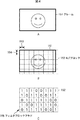
ここで、ALFブロックおよびフィルタブロックフラグについて説明する。図4は、ALFブロックおよびフィルタブロックフラグを説明する図である。 Here, the ALF block and the filter block flag will be described. FIG. 4 is a diagram for explaining the ALF block and the filter block flag.
上述したように、適応フィルタは、フレーム毎にフィルタ係数が設定される。つまり、フレーム単位で最適なフィルタ処理が行われる。しかしながら、一般的に、フレーム画像は、全体が均一でなく、局所的に様々な特徴を有している。そのため、局所的には最適なフィルタ係数が異なる。したがって、上述したようにフレーム毎に決定されるフィルタ係数を用いたフィルタ処理では、フレーム全体では画質を改善するが、局所的には逆に悪化させてしまう恐れがあった。 As described above, in the adaptive filter, a filter coefficient is set for each frame. That is, optimal filter processing is performed on a frame basis. However, in general, the frame image is not uniform as a whole and has various features locally. Therefore, the optimum filter coefficient is locally different. Therefore, as described above, in the filter processing using the filter coefficient determined for each frame, the image quality is improved in the entire frame, but there is a possibility that it may be deteriorated locally.
そこで、局所的に画質が悪化する領域にはフィルタ処理を行わないようにするBALF(Block based Adaptive Loop Filter)が考えられた。 In view of this, a BALF (Block based Adaptive Loop Filter) has been considered in which filter processing is not performed in a region where image quality locally deteriorates.
図4Aのフレーム151は、デブロックフィルタ処理後の復号画像を示す。ブロック情報生成部132は、図4Bに示されるように、それぞれが、局所的に行われる適応フィルタ処理の制御単位となる制御ブロックである、複数のALFブロック152を、このフレーム151の領域全体に敷き詰めるように隙間無く配置する。このALFブロック152が配置される領域は、フレーム151の領域と同一でなくても良いが、少なくともフレームの領域全体を含む。結果として、フレーム151の領域は、各ALFブロック152の領域(複数の領域)に分割される。
A
ブロック情報生成部132は、ALFブロック152の水平方向のサイズ(両矢印153)と、垂直方向のサイズ(両矢印154)とを決定する。ALFブロックのサイズは、例えば、8×8、16×16、24×24、32×32、48×48、64×64、96×96、あるいは128×128のいずれか1つをスライス毎に指定することができる。なお、そのALFブロックのサイズを指定する情報をブロックサイズインデックスと称する。
The block
ブロックサイズが決まれば、フレームサイズは固定であるので、1フレーム当たりのALFブロック数も決定される。 If the block size is determined, the frame size is fixed, so the number of ALF blocks per frame is also determined.
ブロック情報生成部132は、図4Cに示されるように、ALFブロック152毎に、フィルタ処理を行うか否かを制御するフィルタブロックフラグ155を設定する。例えば、適応フィルタにより画質が改善される領域については、値が「1」のフィルタブロックフラグ155が生成され、適応フィルタにより画質が悪化する領域については、値が「0」のフィルタブロックフラグ155が生成される。フィルタブロックフラグ155において、値「1」は、フィルタ処理を行うことを示す値であり、値「0」は、フィルタ処理を行わないことを示す値である。
As illustrated in FIG. 4C, the block
適応フィルタ処理部113は、このフィルタブロックフラグ155の値に基づいて適応フィルタ処理を制御する。例えば、適応フィルタ処理部113は、フィルタブロックフラグ155の値が「1」のALFブロック152の領域にのみフィルタ処理を行い、フィルタブロックフラグ155の値が「0」のALFブロック152の領域にはフィルタ処理を行わない。
The adaptive
また、上述したブロックサイズインデックスとフィルタブロックフラグは、画像圧縮情報のスライスヘッダに含められ、画像符号化装置100から画像復号化装置へ送られる。ALFブロックの数に応じた1個以上のフィルタブロックフラグは、例えばラスタ・スキャンの順序でスライスヘッダに含められる。 The block size index and the filter block flag described above are included in the slice header of the image compression information, and are sent from the image coding apparatus 100 to the image decoding apparatus. One or more filter block flags corresponding to the number of ALF blocks are included in the slice header in the raster scan order, for example.
従って、ALFブロックのサイズが小さい程、より細かなフィルタ制御が可能になり、より適切なALFフィルタが可能となる。ただし、ALFブロックのサイズを小さくすると、フィルタブロックフラグのビット量が増加する。つまり、ALFブロックのサイズが小さい程、画像圧縮情報の符号化効率が低減する。このように、適応フィルタの性能と画像圧縮情報の符号化効率は、トレードオフの関係にある。 Therefore, as the ALF block size is smaller, finer filter control is possible, and a more appropriate ALF filter is possible. However, if the size of the ALF block is reduced, the bit amount of the filter block flag increases. That is, as the size of the ALF block is smaller, the encoding efficiency of the image compression information is reduced. Thus, the performance of the adaptive filter and the coding efficiency of the image compression information are in a trade-off relationship.
ALFブロックの数は次の式(1)のように算出される。 The number of ALF blocks is calculated as in the following equation (1).

式(1)においてNALFBLOCKは、ALFブロックの数を示す。また、NMBwは、ピクチャの水平方向のマクロブロック数を示し、NMBhは、ピクチャの垂直方向のマクロブック数を示す。さらに、NSIZEは、ALFブロックの一辺のサイズを示す。また、floor[x]は、xの少数点以下を切り捨てて、整数にする関数である。 In Formula (1), N ALFBLOCK indicates the number of ALF blocks. N MBw represents the number of macroblocks in the horizontal direction of the picture, and N MBh represents the number of macrobooks in the vertical direction of the picture. Further, N SIZE indicates the size of one side of the ALF block. Floor [x] is a function that rounds off the decimal point of x to an integer.
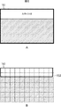
ところで、H.264/AVCでは、1フレームを複数スライスに分割し、そのスライス毎に画像圧縮情報を出力するようにすることができる。図5は、マルチスライスの例を説明する図である。図5の例の場合、フレーム151は、スライス0、スライス1、およびスライス2の3つのスライスに分割されている。
By the way, in H.264 / AVC, one frame can be divided into a plurality of slices, and image compression information can be output for each slice. FIG. 5 is a diagram illustrating an example of multi-slice. In the example of FIG. 5, the
このようなフレームより細かなスライス単位で画像圧縮情報を出力することにより、画像符号化装置は、画像圧縮情報をより短い間隔で生成し、出力することができる。つまり、その画像圧縮情報を復号する画像復号装置は、より早期に画像圧縮情報の復号を開始することができる。つまり、画像が入力されてから、符号化処理および復号処理が行われ、画像が出力されるまでの遅延時間を短くすることができる。 By outputting the image compression information in units of slices smaller than such a frame, the image encoding device can generate and output the image compression information at shorter intervals. That is, an image decoding apparatus that decodes the compressed image information can start decoding the compressed image information earlier. That is, the delay time from when an image is input to when the encoding process and the decoding process are performed and the image is output can be shortened.
BALFについて記載されている非特許文献2には、このマルチスライスについて開示されていない。つまり、ALFブロックをフレーム全体について設定することしか記載されていない。フィルタブロックフラグの生成には、デブロックフィルタされた復号画像が必要になる。したがって、仮にフレーム全体のフィルタブロックフラグを1度に生成するようにすると、フレーム内の全スライスについて画像が符号化されるまで(デブロックフィルタされた復号画像が得られるまで)待機する必要が生じる。この場合、そのために遅延時間が増大し、スライス単位で処理を行う意味が無くなってしまう。 Non-patent document 2 describing BALF does not disclose this multi-slice. That is, only the setting of the ALF block for the entire frame is described. In order to generate the filter block flag, a deblocked decoded image is required. Therefore, if the filter block flag for the entire frame is generated at a time, it is necessary to wait until an image is encoded for all slices in the frame (until a decoded image subjected to deblocking filtering is obtained). . In this case, the delay time increases for this reason, and the meaning of performing processing in units of slices is lost.
したがって、マルチスライスの場合、遅延時間の増大を抑制するために、スライス毎にALFブロックを設定し、フィルタブロックフラグを生成することが望ましい。しかしながら、上述したようにALFブロックは、フレーム全体について設定される。つまり、スライス毎にフレーム全体についてのALFブロックが設定されることになり、スライスの領域外の不要なALFブロックが設定される恐れがあった。 Therefore, in the case of multi-slice, it is desirable to set an ALF block for each slice and generate a filter block flag in order to suppress an increase in delay time. However, as described above, the ALF block is set for the entire frame. That is, an ALF block for the entire frame is set for each slice, and there is a possibility that an unnecessary ALF block outside the slice area is set.
例えば、図5の例において図6Aに示されるようにスライス0を処理する場合、図6Bに示されるように、枠161で示されるスライス0の領域に対して、フレーム151全体についてのALFブロック152が設定される。
For example, when the
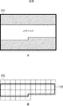
同様に、例えば、図5の例において図7Aに示されるようにスライス1を処理する場合、図7Bに示されるように、枠162で示されるスライス1の領域に対して、フレーム151全体についてのALFブロック152が設定される。
Similarly, for example, in the case of
図6Bおよび図7Bにおいて斜線模様で示されるALFブロック152は、スライス0またはスライス1の領域外のブロックであり、スライス0またはスライス1の領域の処理に対して不要なブロックである。
6B and 7B, the ALF block 152 indicated by hatching is a block outside the area of
上述したように、各ALFブロックには、フィルタブロックフラグ155が設定される。すなわち、マルチスライスの場合、不要なフィルタブロックフラグが発生し、画像圧縮情報のデータ量を増大させ、符号化効率を低減させる恐れがあった。 As described above, the filter block flag 155 is set in each ALF block. That is, in the case of multi-slice, an unnecessary filter block flag is generated, which may increase the data amount of the image compression information and reduce the encoding efficiency.
そこで、図3の制御情報生成部112のブロック情報生成部132は、このような符号化効率の低減を抑制するために、処理対象のスライスの領域を含むALFブロックおよびフィルタブロックフラグを生成する。
Therefore, the block
例えば、図5の例において図8Aに示されるようにスライス1を処理する場合、ブロック情報生成部132は、図8Bに示されるように、枠162で示されるスライス1の領域に対して、その領域を含むALFブロック152のみを設定し、このALFブロック152についてのみフィルタブロックフラグを生成する。
For example, when the
このようにすることにより、画像圧縮情報には、各スライスに必要なフィルタブロックフラグのみが付加されるようになり、上述したように、スライス毎にフレーム全体のフィルタブロックフラグを生成する場合に比べて、フィルタブロックフラグのビット量が低減するので、符号化効率の低減が抑制される。また、スライス毎に制御情報を含む画像圧縮情報が生成されるので、画像復号装置は、スライス単位で画像復号処理を開始することができ、フレーム毎にフィルタブロックフラグを生成する場合に比べて、遅延時間の増大を抑制することができる。 In this way, only the filter block flag necessary for each slice is added to the image compression information. As described above, the filter block flag for the entire frame is generated for each slice. Thus, since the bit amount of the filter block flag is reduced, the reduction in coding efficiency is suppressed. In addition, since image compression information including control information is generated for each slice, the image decoding apparatus can start image decoding processing in units of slices, compared to a case where a filter block flag is generated for each frame. An increase in delay time can be suppressed.
図3に戻り、ブロック情報生成部132は、処理対象スライス領域特定部141、ALFブロック設定部142、処理対象ALFブロック領域特定部143、判定部144、およびフィルタブロックフラグ生成部145を有する。
Returning to FIG. 3, the block
処理対象スライス領域特定部141は、復号画像として供給される処理対象スライスの領域の、フレーム全体における位置を特定する。
The processing target slice
ALFブロック設定部142は、ALFブロックサイズを決定し、フレーム全体のALFブロック152を設定する。フレーム全体の領域の大きさは予め定められているので、ALFブロック設定部142は、決定したALFブロックサイズから、フレーム全体のALFブロック数を特定することができる。
The ALF
処理対象ALFブロック領域特定部143は、ALFブロック設定部142により設定されたALFブロック152から、処理対象とするALFブロックを1つずつ選択し、選択した処理対象ALFブロックの領域の位置を特定する。
The processing target ALF block
判定部144は、処理対象ALFブロックの領域が、処理対象スライスの領域を含むか否かを判定する。フィルタブロックフラグ生成部145は、判定部144によって、「処理対象スライスの領域を含む」と判定されたALFブロックのフィルタブロックフラグを生成する。フィルタブロックフラグ生成部145は、フィルタ係数算出部131により算出されたフィルタ係数を用いて、処理対象ALFブロックの領域に対して適応フィルタ処理を行い、フィルタ処理結果の画質が処理前より改善されているか否かによって、フィルタブロックフラグの値を決定する。
The
フィルタブロックフラグ生成部145は、フィルタブロックフラグおよびALFブロックサイズ等の制御情報を出力する。
The filter block
図9は、図1の適応フィルタ処理部113の主な構成例を示すブロック図である。
FIG. 9 is a block diagram illustrating a main configuration example of the adaptive
適応フィルタ処理部113は、制御情報生成部112から供給される制御情報を用いて、デブロックフィルタ111から供給される復号画像にフィルタ処理を行う。
The adaptive
適応フィルタ処理部113は、図9に示されるように、制御部171、適応フィルタ172、および選択部173を有する。
As illustrated in FIG. 9, the adaptive
制御部171は、適応フィルタ172および選択部173を制御する。例えば、制御部171は、制御情報生成部112から制御情報を取得する。また、制御部171は、取得した制御情報に含まれるフィルタ係数を適応フィルタ172に供給し、設定する。さらに、制御部171は、制御情報に含まれるALFブロックサイズに基づいて、処理対象とするALFブロックの領域の位置を特定する。また、制御部171は、制御情報に含まれるフィルタブロックフラグの値に基づいて、適応フィルタ172を制御し、各ALFブロックの領域を必要に応じてフィルタ処理させるとともに、選択部173の動作を制御する。
The
適応フィルタ172は、デブロックフィルタ111から供給される復号画像の、制御部171から処理対象ALFブロックとして指定される領域を、制御部171により設定されたフィルタ係数を用いてフィルタ処理する。適応フィルタ172は、フィルタ処理結果を選択部173に供給する。
The
選択部173は、制御部171に制御され、デブロックフィルタ111から供給された復号画像(適応フィルタ処理されていない復号画像)と、適応フィルタ172から供給された復号画像(適応フィルタ処理された復号画像)とのうち、いずれか一方を選択し、フレームメモリ114に供給し、参照画像として蓄積させる。
The
つまり、適応フィルタ処理部113は、デブロックフィルタ111から供給される復号画像の、フィルタブロックフラグによってフィルタ処理を行うことが示された領域(フィルタ処理によって画質が改善されると判定された領域)のみフィルタ処理を行う。
That is, the adaptive
[処理の流れ]
次に、以上のように構成される各部を用いた処理の流れについて説明する。最初に、画像符号化装置100により行われる符号化処理の流れの例を、図10のフローチャートを参照して説明する。
[Process flow]
Next, the flow of processing using each unit configured as described above will be described. First, an example of the flow of encoding processing performed by the image encoding device 100 will be described with reference to the flowchart of FIG.
ステップS101において、A/D変換部101は入力された画像をA/D変換する。ステップS102において、画面並べ替えバッファ102は、A/D変換された画像を記憶し、各ピクチャの表示する順番から符号化する順番への並べ替えを行う。
In step S101, the A /
ステップS103において、演算部103は、ステップS102の処理により並び替えられた画像と、予測画像との差分を演算する。予測画像は、インター予測する場合は動き補償部116から、イントラ予測する場合はイントラ予測部115から、それぞれ予測画像選択部118を介して演算部103に供給される。
In step S103, the
差分データは元の画像データに較べてデータ量が小さくなっている。したがって、画像をそのまま符号化する場合に較べて、データ量を圧縮することができる。 The difference data has a smaller data amount than the original image data. Therefore, the data amount can be compressed as compared with the case where the image is encoded as it is.
ステップS104において、直交変換部104は、ステップS103の処理により生成された差分情報を直交変換する。具体的には、離散コサイン変換、カルーネン・レーベ変換等の直交変換が行われ、変換係数が出力される。ステップS105において、量子化部105は変換係数を量子化する。この量子化に際しては、後述するステップS119の処理で説明されるように、レートが制御される。
In step S104, the
以上のようにして量子化された差分情報は、次のようにして局部的に復号される。すなわち、ステップS106において、逆量子化部108は量子化部105により量子化された変換係数を量子化部105の特性に対応する特性で逆量子化する。ステップS107において、逆直交変換部109は逆量子化部108により逆量子化された変換係数を直交変換部104の特性に対応する特性で逆直交変換する。
The difference information quantized as described above is locally decoded as follows. That is, in step S106, the
ステップS108において、演算部110は、予測画像選択部118を介して入力される予測画像を局部的に復号された差分情報に加算し、局部的に復号された画像(演算部103への入力に対応する画像)を生成する。ステップS109においてデブロックフィルタ111は、演算部110より出力された画像をフィルタリングする。これによりブロック歪みが除去される。
In step S108, the
以上の処理が、1スライス分行われると、ステップS110において、制御情報生成部112は、適応フィルタ処理に用いられる制御情報を生成する。制御情報の生成処理の詳細については後述する。
When the above processing is performed for one slice, in step S110, the control
ステップS110の処理により、フィルタ係数、ALFブロックサイズ、およびフィルタブロックフラグ等の制御情報が生成されると、適応フィルタ処理部113は、ステップS111において、その制御情報を用いて、ステップS109の処理によりデブロックフィルタ処理された復号画像に対して適応フィルタ処理を行う。この適応フィルタ処理の詳細については後述する。
When control information such as a filter coefficient, an ALF block size, and a filter block flag is generated by the process in step S110, the adaptive
ステップS112において、フレームメモリ114は、ステップS111において適応フィルタ処理された画像を記憶する。
In step S112, the
ステップS113において、イントラ予測部115は、イントラ予測モードのイントラ予測処理を行う。ステップS114において、動き予測部117および動き補償部116は、インター予測モードのインター動き予測・補償処理を行う。
In step S113, the
ステップS115において、予測画像選択部118は、処理対象フレームの予測モードに応じて、イントラ予測処理により生成された予測画像、または、インター動き予測・補償処理により生成された予測画像のうち、いずれか一方を選択する。予測画像選択部118は、選択した予測画像を演算部103および演算部110に供給する。この予測画像が、上述したように、ステップS103、およびステップS108の演算に利用される。
In step S115, the predicted
ステップS116において、可逆符号化部106は量子化部105より出力された量子化された変換係数を符号化する。すなわち、差分画像が可変長符号化、算術符号化等の可逆符号化され、圧縮される。このとき、可逆符号化部106は、ステップS110において生成された制御情報、ステップS113のイントラ予測処理のイントラ予測モード情報、および、ステップS114のインター動き予測・補償処理のインター予測モード等も符号化する。
In step S116, the
ステップS117において、可逆符号化部106は、符号化した制御情報等のメタデータをスライスヘッダに埋め込む(記述する)。このメタデータは、画像復号時に読み出され利用される。このように復号処理に必要なメタデータをスライスヘッダに含める(多重化する)ことにより、フレーム単位より細かい単位での復号処理の実行が可能になり、遅延時間の増大を抑制することができる。
In step S117, the
ステップS118において蓄積バッファ107は、差分画像を圧縮画像として蓄積する。蓄積バッファ107に蓄積された圧縮画像は、適宜読み出され、伝送路を介して復号側に伝送される。
In step S118, the
ステップS119においてレート制御部119は、蓄積バッファ107に蓄積された圧縮画像に基づいて、オーバーフローあるいはアンダーフローが発生しないように、量子化部105の量子化動作のレートを制御する。
In step S119, the
次に、図10のステップS110において制御情報生成部112により実行される制御情報生成処理の流れの例を、図11のフローチャートを参照して説明する。
Next, an example of the flow of control information generation processing executed by the control
制御情報生成処理が開始されると、制御情報生成部112のフィルタ係数算出部131は、ステップS131において、画面並べ替えバッファ102から供給される入力画像と、デブロックフィルタ111から供給されるデブロックフィルタ処理された復号画像を用いてフィルタ係数を算出する。例えば、フィルタ係数算出部131は、入力画像と復号画像の残差が最小となるようにフィルタ係数の値を決定する。
When the control information generation process is started, the filter
フィルタ係数が算出されると、ブロック情報生成部132は、ステップS132において、ALFブロックサイズやフィルタブロックフラグを含むブロック情報の生成を行う。ブロック情報生成処理の詳細については後述する。ブロック情報が生成されると、図10のステップS110に戻り、ステップS111以降の処理が実行される。
When the filter coefficient is calculated, the block
なお、ステップS131において行われるフィルタ係数の算出は、フレーム単位で行うようにしてもよい。その場合、ステップS131の処理は、フレーム内の所定のスライス(例えば、フレーム内で識別番号が所定の値の(例えば「0」の)スライス、若しくは、フレーム内で最初に処理されるスライス等)においてのみ行われ、その他のスライスにおいては、その値が流用されるようにしてもよい。また、フィルタ係数の算出には、任意の画像を利用することができる。例えば、過去のフレーム画像に基づいて算出するようにしてもよい。
Note that the filter coefficient calculation performed in step S131 may be performed in units of frames. In this case, the process in step S131 is performed for a predetermined slice in the frame (for example, a slice whose identification number has a predetermined value (for example, “0”) or a slice that is processed first in the frame). It may be performed only in
次に、図12のフローチャートを参照して、図11のステップS132において実行されるブロック情報生成処理の流れの例を説明する。 Next, an example of the flow of block information generation processing executed in step S132 of FIG. 11 will be described with reference to the flowchart of FIG.
ブロック情報生成処理が開始されると、処理対象スライス領域特定部141は、ステップS151において、処理対象スライスの領域を特定する。
When the block information generation process is started, the processing target slice
処理対象である当該スライスの領域を知るためには、当該スライスに含まれているマクロブロックを知り、そこからそのマクロブロックに含まれる画素を知ることで分かる。処理対象スライス領域特定部141は、スライスヘッダから当該スライスの先頭マクロブロックアドレスを得る。
In order to know the area of the slice to be processed, it is known by knowing the macroblock contained in the slice and then knowing the pixels contained in the macroblock. The processing target slice
ここで先頭マクロブロックアドレスとは、画面の左上からラスタ・スキャン順序でマクロブロックに対して付けられた番号である。図5に示されるように、画像(フレーム151)の左上のマクロブロックアドレスは0となる。スライス0は、フレーム151の左上から開始されているので、スライス0の先頭マクロブロック156−1のマクロブロックアドレスは0となる。この順序に従ってスライス0の最終マクロブロック156−2のマクロブロックアドレスをE0とする。また、このスライス0と同様に、スライス1の先頭マクロブロック157−1のマクロブロックアドレスをS1とし、最終マクロブロック157−2のマクロブロックアドレスをE1とする。さらに、スライス2の先頭マクロブロック158−1のマクロブロックアドレスをS2とし、最終マクロブロック158−2のマクロブロックアドレスをE2とする。
Here, the head macroblock address is a number assigned to the macroblock in the raster scan order from the upper left of the screen. As shown in FIG. 5, the macro block address at the upper left of the image (frame 151) is 0. Since
当該スライスをデコードしていくと、1つのマクロブロックのデコード処理が完了する毎にマクロブロックアドレスは1追加されてゆき、やがて当該スライスの最終マクロブックに到達する。最終マクロブロックにはスライスの最後のマクロブロックであるフラグがセットされている。これらによって、当該スライスが保有しているマクロブロックアドレスが全て分かる。すなわち、先頭マクロブロックアドレスから、最終マクロブロックアドレスまでとなる。 When the slice is decoded, one macroblock address is added every time decoding processing of one macroblock is completed, and eventually the final macrobook of the slice is reached. A flag which is the last macroblock of the slice is set in the last macroblock. As a result, all the macroblock addresses held by the slice can be known. That is, from the first macro block address to the last macro block address.
ところで、1フレームの画像サイズは、AVCストリーム(画像圧縮情報)のシーケンス・パラメータ・セット(SPS(Sequence Parameter Set))において、マクロブロックの数により示される。pic_height_in_map_units_minus1は、画像の縦方向のマクロブロック数を示す。pic_width_in_mbs_minus1は、画像の横方向のマクロブロック数を示す。 By the way, the image size of one frame is indicated by the number of macroblocks in the sequence parameter set (SPS (Sequence Parameter Set)) of the AVC stream (image compression information). pic_height_in_map_units_minus1 indicates the number of macroblocks in the vertical direction of the image. pic_width_in_mbs_minus1 indicates the number of macroblocks in the horizontal direction of the image.
従って、マクロブロックアドレスからそのマクロブロックの位置は、以下の式(2)および式(3)で示される。 Therefore, the position of the macro block from the macro block address is expressed by the following equations (2) and (3).
mbx=macro block address % pic_width_in_mbs_minus1 ・・・(2)
mby=floor[ macro block address / pic_width_in_mbs_minus1 ] ・・・(3)
mbx = macro block address% pic_width_in_mbs_minus1 (2)
mby = floor [macro block address / pic_width_in_mbs_minus1] (3)
式(2)および式(3)において、mbxは、マクロブロックが左から何番目かを示し、mbyは、マクロブロックが上から何番目かを示す。また、floor[z]は、zの小数点以下を切り捨てて整数にし、A%Bは、AをBで割った余りの数を示す。 In Expression (2) and Expression (3), mbx indicates the number of the macroblock from the left, and mby indicates the number of the macroblock from the top. Further, floor [z] rounds down the decimal part of z to an integer, and A% B indicates the remainder obtained by dividing A by B.
マクロブロックのサイズは16×16画素と決められているとすると、マクロブロックの左上の画素の縦方向および横方向の位置は、(16×mbx,16×mby)となり、そのマクロブロックに含まれる画素は、その左上の画素位置から下方向に16画素および右方向に16画素の範囲に含まれる画素となる。ここまでで、当該スライスの画素が全て分かる。すなわち、処理対象スライスの領域が特定される。 If the size of the macroblock is determined to be 16 × 16 pixels, the vertical and horizontal positions of the upper left pixel of the macroblock are (16 × mbx, 16 × mby) and are included in the macroblock. The pixel is a pixel included in a range of 16 pixels downward from the pixel position at the upper left and 16 pixels rightward. Up to this point, all the pixels of the slice are known. That is, the area of the processing target slice is specified.
図12のステップS152において、ALFブロック設定部142は、ALFブロックサイズを決定する。ステップS153において、ALFブロック設定部142は、フレーム内ALFブロック数を決定する。フレームの画像サイズは予め定められているので、ALFブロックサイズが決定されると、フレームの左上を原点としてALFブロックを敷き詰めるために必要なALFブロックの数(フレーム内ALFブロック数)も算出することができる。ALFブロックの縦方向のサイズ(画素数)と横方向のサイズ(画素数)の設定値は予め用意されているので、ALFブロック設定部142は、その設定値に従って各ALFブロックのサイズとALFブロック数を決定し、ALFブロックを復号画像に対して配置する。
In step S152 of FIG. 12, the ALF
なお、ALFブロックの数は、以下の式(4)および式(5)により算出される。 The number of ALF blocks is calculated by the following formulas (4) and (5).
num_alf_block_x=floor[(16×(pic_width_in_mbs_minus1+1)+(alf_block_size−1))
/alf_block_size] ・・・(4)
num_alf_block_y=floor[(16×(pic_height_in_map_units_minus1+1)
+(alf_block_size−1))/alf_block_size] ・・・(5)
num_alf_block_x = floor [(16 × (pic_width_in_mbs_minus1 + 1) + (alf_block_size−1))
/ Alf_block_size] (4)
num_alf_block_y = floor [(16 × (pic_height_in_map_units_minus1 + 1)
+ (Alf_block_size−1)) / alf_block_size] (5)
式(4)および式(5)において、num_alf_block_xおよびnum_alf_block_yは、それぞれ、画像に含まれるALFブロックの横と縦の数である。また、alf_block_sizeは、ALFブロックの一辺のサイズを示す。ここでは説明の簡略化のため、ALFブロックは正方形であるものとする。もちろん、ALFブロックの縦方向のサイズと横方向のサイズとが互いに異なるようにしてもよい。 In Expression (4) and Expression (5), num_alf_block_x and num_alf_block_y are the horizontal and vertical numbers of ALF blocks included in the image, respectively. Alf_block_size indicates the size of one side of the ALF block. Here, for simplification of description, the ALF block is assumed to be a square. Of course, the vertical size and the horizontal size of the ALF block may be different from each other.
ステップS154において、処理対象ALFブロック領域特定部143は、処理対象ALFブロックを決定する。ステップS155において、処理対象ALFブロック領域特定部143は、その処理対象ALFブロックの領域を特定する。
In step S154, the processing target ALF block
i番目のALFブロックの位置は、以下の式(6)および式(7)で示される。 The position of the i-th ALF block is expressed by the following equations (6) and (7).
alf_block_x=i % (num_alf_block_x−1) ・・・(6)
alf_block_y=floor[i/(num_alf_block_x−1)] ・・・(7)
alf_block_x = i% (num_alf_block_x−1) (6)
alf_block_y = floor [i / (num_alf_block_x−1)] (7)
式(6)および式(7)において、alf_block_xとalf_block_yは、それぞれ、i番目のALFブロックが横方向と縦方向に何番目であるかを示している。i番目のALFブロックの左上の画素の位置は、alf_block_xとalf_block_yのそれぞれに、alf_block_sizeを掛けた位置となる。すなわち、横方向は16×alf_block_xとなり、縦方向は16×alf_block_yとなる。従って、i番目のALFブロックの領域は、左上のその画素からalf_block_size×alf_block_sizeの範囲となる。 In Expression (6) and Expression (7), alf_block_x and alf_block_y indicate the number of the i-th ALF block in the horizontal direction and the vertical direction, respectively. position of the top left pixel of the i-th ALF blocks, each of alf_block_x and alf _Block_y, the position multiplied by Alf_block_size. That is, the horizontal direction is 16 × alf_block_x, and the vertical direction is 16 × alf_block_y. Therefore, the area of the i-th ALF block is a range of alf_block_size × alf_block_size from the upper left pixel.
ステップS156において、判定部144は、以上のように特定された処理対象ALFブロックの領域内に、処理対象スライスの領域が含まれるか否かを判定する。
In step S156, the
処理対象ALFブロックの領域内に処理対象スライスの領域が含まれると判定された場合、ステップS157に進む。ステップS157においてフィルタブロックフラグ生成部145は、処理対象ALFブロックが処理対象スライスにとって必要なALFブロックであるので、そのALFブロックについてフィルタブロックフラグを生成する。ステップS158において、フィルタブロックフラグ生成部145は、生成したフィルタブロックフラグを出力する。
If it is determined that the area of the processing target slice is included in the area of the processing target ALF block, the process proceeds to step S157. In step S157, the filter block
ステップS158の処理が終了するとステップS159に進む。また、ステップS156において、処理対象ALFブロックの領域内に処理対象スライスの領域が含まれないと判定された場合、そのALFブロックは、処理対象スライスにとって不要であるのでステップS159に進む。 When the process of step S158 ends, the process proceeds to step S159. If it is determined in step S156 that the area of the processing target slice is not included in the area of the processing target ALF block, the ALF block is unnecessary for the processing target slice, and the process proceeds to step S159.
ステップS159において、処理対象ALFブロック領域特定部143は、フレーム内ALFブロックを全て処理したか否かを判定し、処理していないと判定された場合、ステップS154に戻り、新たなALFブロックを処理対象とし、それ以降の処理を繰り返す。処理対象ALFブロック領域特定部143は、このループ処理を繰り返す度に、フレームの領域に敷き詰められたALFブロック群の中からALFブロックを、処理対象ALFブロックとして、左上のALFブロックからラスタ・スキャン順に1つずつ選択する。
In step S159, the processing target ALF block
また、ステップS159において、フレーム内ALFブロックを全て処理したと判定された場合、ブロック情報生成処理が終了され、図11のステップS132に戻り、制御情報生成処理が終了され、図10のステップS110に戻り、ステップS111以降の処理が行われる。 If it is determined in step S159 that all the ALF blocks in the frame have been processed, the block information generation process ends, the process returns to step S132 in FIG. 11, the control information generation process ends, and the process proceeds to step S110 in FIG. Returning, the process after step S111 is performed.
なお、以上において、ALFブロックをフレーム画像の領域に敷き詰めるように配置する際に、フレームの左上を原点とするように説明したが、この原点の位置は任意である。例えば、フレームの左下、右下、右上、または中心であってもよい。ただし、この原点の位置およびALFブロックの並べ方は、符号化処理と復号処理とで共通とするように予め取り決めておく必要がある。 In the above description, when the ALF block is arranged so as to cover the frame image area, the upper left corner of the frame is used as the origin, but the position of the origin is arbitrary. For example, it may be the lower left, lower right, upper right, or center of the frame. However, the position of the origin and the way of arranging the ALF blocks need to be determined in advance so as to be common to the encoding process and the decoding process.
また、以上においては、処理対象ALFブロックを選択する順を、左上からラスタ・スキャン順とするように説明したが、この選択順および開始位置は任意である。 In the above description, the order in which the processing target ALF blocks are selected is described as the raster scan order from the upper left, but the selection order and the start position are arbitrary.
次に、図13のフローチャートを参照して、図10のステップS111において実行される適応フィルタ処理の流れの例を説明する。 Next, an example of the flow of adaptive filter processing executed in step S111 in FIG. 10 will be described with reference to the flowchart in FIG.
適応フィルタ処理が開始されると、適応フィルタ172および選択部173には、処理対象スライスの復号画像が供給される。ステップS171において、制御部171は、その処理対象スライスの領域を特定する。制御部171は、図12のステップS151の処理の場合と同様に、スライスヘッダの当該スライスの先頭マクロブロックアドレスを取得し、さらに最終マクロブロックを示すフラグを検出し、先頭のマクロブロックアドレスから最終マクロブロックアドレスまでの領域を処理対象スライスの領域として特定する。
When the adaptive filter process is started, the decoded image of the processing target slice is supplied to the
制御部171は、ステップS172において、制御情報生成部112により生成されたフィルタ係数を取得し、そのフィルタ係数を適応フィルタ172に設定する。ステップS173において、制御部171は、制御情報生成部112により決定されたALFブロックサイズを取得し、フレームの領域全体に対してそのALFブロックサイズのALFブロックを敷き詰めるように設定(配置)する。
In
ステップS174において、制御部171は、このように設定されたALFブロック群のうち、未処理のALFブロックの中から1つを、図12のステップS154の場合と同様に、処理対象ALFブロックに決定する。このALFブロックの選択順は、予め定められており、制御情報生成部112における選択順と共通である。
In step S174, the
ステップS175において、制御部171は、決定した処理対象ALFブロックの領域を、図12のステップS155の場合と同様に特定する。
In step S175, the
ステップS176において、制御部171は、図12のステップS156の場合と同様に、処理対象ALFブロックの領域内に処理対象スライスの領域が含まれるか否かを判定する。含まれると判定された場合、ステップS177に進む。
In step S176, the
ステップS177において、制御部171は、制御情報生成部112において生成された処理対象ALFブロックのフィルタブロックフラグを取得する。制御情報生成部112が、上述したようにフィルタブロックフラグを生成するので、実際には、処理対象スライスの領域を含むALFブロックについてのみフィルタブロックフラグが供給される。ALFブロックの処理順が制御情報生成部112と共通であるので、フィルタブロックフラグは、ALFブロックの処理順に供給される。したがって、制御部171は、その供給順にフィルタブロックフラグを取得(採用)することにより、処理対象ALFブロックのフィルタブロックフラグを取得(採用)することができる。
In step S177, the
なお、フィルタブロックフラグの供給タイミングと、制御部171によるフィルタブロックフラグの取得タイミングは、一致していなくても良い。つまり、制御部171が、制御情報生成部112から供給されたフィルタブロックフラグを、例えば内蔵するバッファ等に一時的に保持し、ステップS177の処理において、そのバッファからフィルタブロックフラグを読み出すようにしてもよい。その場合も、フィルタブロックフラグの読み出し順は、制御情報生成部112から供給される順、すなわち、バッファへの蓄積順と同一となるようにするだけで、制御部171は、処理対象ALFブロックのフィルタブロックフラグを取得することができる。
Note that the supply timing of the filter block flag and the acquisition timing of the filter block flag by the
ステップS178において、制御部171は、フィルタブロックフラグの値が1であるか否かを判定する。フィルタブロックフラグの値が1であり、処理対象ALFブロックの領域についてフィルタ処理を行うように指示されている場合、ステップS179に進む。ステップS179において、適応フィルタ172は、制御部171に制御されて、処理対象ALFブロックにフィルタ処理を行う。ステップS179の処理が終了するとステップS180に進む。この場合、選択部173は、ステップS180において、制御部171に制御されて適応フィルタ172の出力を選択し、フレームメモリ114に出力する。つまり、フィルタ処理された復号画像(の一部の領域)がフレームメモリ114に蓄積される。ステップS180の処理が終了するとステップS181に進む。
In step S178, the
また、ステップS178において、フィルタブロックフラグの値が0であり、処理対象ALFブロックの領域についてフィルタ処理が行われないように指示されている場合、ステップS179の処理を省略し、ステップS180に進む。この場合、選択部173は、ステップS180において、制御部171に制御されてデブロックフィルタ111の出力を選択し、フレームメモリ114に出力する。つまり、フィルタ処理されていない復号画像(の一部の領域)がフレームメモリ114に蓄積される。ステップS180の処理が終了するとステップS181に進む。
In step S178, when the value of the filter block flag is 0, and it is instructed not to perform the filter process for the area of the processing target ALF block, the process of step S179 is omitted, and the process proceeds to step S180. In this case, in step S180, the
また、ステップS176において、処理対象ALFブロックの領域内に処理対象スライスの領域が含まれないと判定された場合、処理対象ALFブロックは処理対象スライスに関係の無いALFブロックであるので、ステップS177乃至ステップS180の処理を省略し、ステップS181に進む。 If it is determined in step S176 that the region of the processing target slice is not included in the region of the processing target ALF block, the processing target ALF block is an ALF block that is not related to the processing target slice, and thus steps S177 to S177 are performed. The process of step S180 is omitted, and the process proceeds to step S181.
ステップS181において、制御部171は、フレーム内ALFブロックを全て処理したか否かを判定する。未処理のALFブロックが存在すると判定された場合、ステップS174に戻り、新たな処理対象ALFブロックについてそれ以降の処理を繰り返す。制御部171は、このループ処理を繰り返す度に、フレームの領域に敷き詰められたALFブロック群の中からALFブロックを、処理対象ALFブロックとして、左上のALFブロックからラスタ・スキャン順に1つずつ選択する。
また、ステップS181において、フレーム内ALFブロックを全て処理したと判定された場合、適応フィルタ処理が終了され、図10のステップS111に戻り、ステップS112以降の処理が行われる。
In step S181, the
If it is determined in step S181 that all the ALF blocks in the frame have been processed, the adaptive filter process is terminated, the process returns to step S111 in FIG. 10, and the processes after step S112 are performed.
以上のように適応フィルタ処理を行うことにより、適応フィルタ処理部113は、フレームに形成される複数のスライスの中の処理対象スライスに必要な、フレーム内の一部のALFブロックのフィルタブロックフラグに基づいて、処理対象スライスに対するフィルタ処理を適切に実行することができる。これにより、適応フィルタ処理部113は、処理対象スライスの、デブロックフィルタにより取りきれなかったブロック歪みや量子化による歪みを低減することができる。
By performing the adaptive filter processing as described above, the adaptive
ALFブロックの配置方法は予め定められている。したがってALFブロックがフレーム全体に敷き詰められるように配置されている状態においては、ALFブロックサイズから各ALFブロックの位置を容易に求めることができる。したがって、従来のように、フレーム内の全てのALFブロックについてフィルタブロックフラグが生成される場合、各フィルタブロックフラグに対応する領域の位置は容易に特定することができる。 The arrangement method of the ALF block is predetermined. Therefore, in the state where the ALF blocks are arranged so as to be spread over the entire frame, the position of each ALF block can be easily obtained from the ALF block size. Therefore, when filter block flags are generated for all ALF blocks in a frame as in the prior art, the position of the area corresponding to each filter block flag can be easily specified.
しかしながら、例えばフレームに複数のスライスが構成されるマルチスライスの場合、フレーム内の一部のALFブロックのフィルタブロックフラグを用いて、処理対象スライスに対するフィルタ処理を制御することが考えられる。このような場合、処理対象スライスの領域の位置によって(すなわち、処理対象スライスが、フレーム内の複数のスライスのいずれであるかによって)、使用されるフィルタブロックフラグが対応する領域の位置が異なる。 However, for example, in the case of a multi-slice in which a plurality of slices are configured in a frame, it is conceivable to control the filter processing for the processing target slice using the filter block flags of some ALF blocks in the frame. In such a case, the position of the region corresponding to the filter block flag to be used differs depending on the position of the region of the processing target slice (that is, whether the processing target slice is a plurality of slices in the frame).
しかしながら、従来の手法では、処理対象スライスやフィルタブロックフラグの位置の特定を行わない。したがって、制御情報生成部112において生成されたフィルタブロックフラグによる制御が適切に作用せず、適応フィルタ処理が適切に行われない恐れがある。
However, the conventional technique does not specify the position of the processing target slice or the filter block flag. Therefore, the control by the filter block flag generated in the control
上述したように適応フィルタ処理部113は、フレーム内の一部の領域である処理対象スライスの領域の位置と、フレーム内の一部のALFブロックのフィルタブロックフラグが対応する領域の位置とを特定するので、適応フィルタ処理を正しく行うことができる。つまり、処理対象スライスの領域を含まないALFブロックの、処理対象スライスに影響を与えないフィルタブロックフラグが不要になるので、適応フィルタ処理部113は、画像圧縮情報の符号化効率の低減を抑制することができる。
As described above, the adaptive
また、制御情報生成部112は、上述したように、処理対象スライスの領域を含むALFブロックについてのみ、フィルタブロックフラグを生成するので、不要なフィルタブロックフラグの生成を抑制し、画像圧縮情報の符号化効率の低減を抑制することができる。
Further, as described above, the control
また、適応フィルタ処理部113は、上述したように、制御情報生成部112と同様の方法を用いることにより、処理対象スライスの領域の位置と、フィルタブロックフラグが対応する領域の位置との特定を容易に行うことができる。
In addition, as described above, the adaptive
また、可逆符号化部106が、ALFブロックサイズおよびフィルタブロックフラグを含むブロック情報を符号化データに付加する(例えばスライスヘッダに埋め込む)ことにより、その符号化データを復号する画像復号装置においても、適応フィルタ処理部113の場合と同様の、ブロック情報に基づいたフィルタ処理を行うことができる。
Also, in the image decoding apparatus in which the
なお、ここで「付加する」とは、任意の形態でブロック情報を符号化データに関連付けることを示す。例えば、符号化データのシンタックスとして記述するようにしてもよいし、ユーザデータとして記述するようにしてもよい。また、ブロック情報をメタデータとして符号化データとリンクされた状態にするようにしてもよい。つまり、「付加」は、「埋め込み」、「記述」、「多重化」、および「連結」等を含む。 Here, “add” indicates that block information is associated with encoded data in an arbitrary form. For example, it may be described as a syntax of encoded data or may be described as user data. Further, block information may be linked to encoded data as metadata. That is, “addition” includes “embedding”, “description”, “multiplexing”, “concatenation”, and the like.
以上のようなブロック情報生成処理や適応フィルタ処理を伴う符号化処理を行うことにより、フィルタブロックフラグを必要なものだけ画像圧縮情報に含めることができるので、画像符号化装置100は、符号化時または復号時のフィルタ処理の局所的な制御による符号化効率の低減を抑制することができる。例えば、画像の各フレームを複数スライスに分け、スライス毎に、適応フィルタを用いた符号化処理を行い、出力する場合においても、画像符号化装置100は、符号化効率の低減を抑制することができる。 By performing the encoding process involving the block information generation process and the adaptive filter process as described above, only the necessary filter block flags can be included in the image compression information. Alternatively, it is possible to suppress a reduction in encoding efficiency due to local control of filter processing during decoding. For example, even when each frame of an image is divided into a plurality of slices, an encoding process using an adaptive filter is performed for each slice, and output, the image encoding device 100 can suppress a decrease in encoding efficiency. it can.
<2.第2の実施の形態>
[デバイスの構成]
次に、第1の実施の形態において説明した画像符号化装置100に対応する画像復号装置について説明する。図14は、本発明を適用した画像処理装置としての画像復号装置の一実施の形態の構成例を示すブロック図である。
<2. Second Embodiment>
[Device Configuration]
Next, an image decoding apparatus corresponding to the image encoding apparatus 100 described in the first embodiment will be described. FIG. 14 is a block diagram showing a configuration example of an embodiment of an image decoding apparatus as an image processing apparatus to which the present invention is applied.
画像復号装置200は、画像符号化装置100より出力される画像圧縮情報を復号し、復号画像を生成する。 The image decoding device 200 decodes the image compression information output from the image encoding device 100 and generates a decoded image.
画像復号装置200は、蓄積バッファ201、可逆復号部202、逆量子化部203、逆直交変換部204、演算部205、およびデブロックフィルタ206を有する。また、画像復号装置200は、適応フィルタ処理部207を有する。さらに、画像復号装置200は、画面並べ替えバッファ208、およびD/A(Digital / Analog l)変換部209を有する。また、画像復号装置200は、フレームメモリ210、イントラ予測部211、動き補償部212、および選択部213を有する。
The image decoding apparatus 200 includes a
蓄積バッファ201は、伝送されてきた画像圧縮情報を蓄積する。可逆復号部202は、蓄積バッファ201より供給された、図1の可逆符号化部106により符号化された情報を、可逆符号化部106の符号化方式に対応する方式で復号する。
The
当該マクロブロックがイントラ符号化されたものである場合、可逆復号部202は、画像圧縮情報のヘッダ部に格納されたイントラ予測モード情報を復号し、その情報をイントラ予測部211へ伝送する。また、当該マクロブロックがインター符号化されたものである場合、可逆復号部202は、画像圧縮情報のヘッダ部に格納された動きベクトル情報を復号し、その情報を動き補償部212へ転送する。
When the macroblock is intra-coded, the
また、可逆復号部202は、画像圧縮情報のスライスヘッダから、適応フィルタ用の制御情報(制御情報生成部112により生成された制御情報)を抽出して復号し、その情報を適応フィルタ処理部207に供給する。
The
逆量子化部203は可逆復号部202により復号された画像を、図1の量子化部105の量子化方式に対応する方式で逆量子化する。逆直交変換部204は、図1の直交変換部104の直交変換方式に対応する方式で逆量子化部203の出力を逆直交変換する。
The
演算部205は、逆直交変換された差分情報に、選択部213から供給される予測画像を加算し、復号画像を生成する。デブロックフィルタ206は、その加算処理されて生成された復号画像のブロック歪を除去する。
The
適応フィルタ処理部207は、可逆復号部202より供給された制御情報に含まれるフィルタ係数、ALFブロックサイズ、およびフィルタブロックフラグ等の情報に基づいて、デブロックフィルタ206より供給される画像に対してフィルタ処理を行う。適応フィルタ処理部207は、図1の適応フィルタ処理部113と同様の適応フィルタ処理を行う。これにより、適応フィルタ処理部207は、デブロックフィルタ206では取りきれなかったブロック歪や量子化による歪を低減することができる。
The adaptive
適応フィルタ処理部207は、フィルタ処理後の画像をフレームメモリ210に供給し、参照画像情報として蓄積させるとともに、画面並べ替えバッファ208に出力する。
The adaptive
画面並べ替えバッファ208は、画像の並べ替えを行う。すなわち、図1の画面並べ替えバッファ102により符号化の順番のために並べ替えられたフレームの順番が、元の表示の順番に並べ替えられる。D/A変換部209は、画面並べ替えバッファ208から供給された画像をD/A変換し、出力する。例えば、D/A変換部209は、D/A変換して得られた出力信号を図示せぬディスプレイに出力し、画像を表示させる。
The
イントラ予測部211は、当該フレームがイントラ符号化されたものである場合、可逆復号部202から供給される情報に基づいて、予測画像を生成し、生成した予測画像を、選択部213に出力する。
The
動き補償部212は、当該フレームがインター符号化されたものである場合、可逆復号部202から供給された動きベクトル情報に基づき、フレームメモリ210に格納された参照画像情報に対して動き補償処理を行う。
When the frame is inter-encoded, the
選択部213は、当該マクロブロックがイントラ符号化されたものである場合、イントラ予測部211に接続し、イントラ予測部211より供給される画像を予測画像として演算部205に供給する。また、当該マクロブロックがインター符号化されたものである場合、選択部213は、動き補償部212に接続し、動き補償部212から供給される画像を予測画像として演算部205に供給する。
When the macroblock is an intra-coded block, the
[処理の流れ]
図15のフローチャートを参照して、この画像復号装置200が実行する復号処理の流れの例を説明する。
[Process flow]
With reference to the flowchart in FIG. 15, an example of the flow of decoding processing executed by the image decoding device 200 will be described.
ステップS201において、蓄積バッファ201は伝送されてきた画像を蓄積する。ステップS202において、可逆復号部202は、蓄積バッファ201から供給される圧縮画像を復号する。すなわち、図1の可逆符号化部106により符号化されたIピクチャ、Pピクチャ、並びにBピクチャが復号される。
In step S201, the
このとき、動きベクトル情報、参照フレーム情報、予測モード情報(イントラ予測モード、またはインター予測モードを示す情報)なども復号される。 At this time, motion vector information, reference frame information, prediction mode information (information indicating an intra prediction mode or an inter prediction mode), and the like are also decoded.
すなわち、予測モード情報がイントラ予測モード情報である場合、予測モード情報は、イントラ予測部211に供給される。予測モード情報がインター予測モード情報である場合、予測モード情報と対応する動きベクトル情報および参照フレーム情報は、動き補償部212に供給される。
That is, when the prediction mode information is intra prediction mode information, the prediction mode information is supplied to the
さらに、可逆復号部202は、ステップS202において、画像圧縮情報のスライスヘッダから適応フィルタ処理用の制御情報を抽出し、復号する。復号された制御情報は、適応フィルタ処理部207に供給される。
In step S202, the
ステップS204において、逆量子化部203は、ステップS202において復号された変換係数を、図1の量子化部105の特性に対応する特性で逆量子化する。ステップS205において逆直交変換部204は、ステップS204の処理により逆量子化された変換係数を、図1の直交変換部104の特性に対応する特性で逆直交変換する。これにより図1の直交変換部104の入力(演算部103の出力)に対応する差分情報が復号されたことになる。
In step S204, the
ステップS206において、演算部205は、後述するステップS212の処理で選択される予測画像を差分情報と加算する。これにより元の画像が復号される。ステップS207において、デブロックフィルタ206は、演算部205より出力された画像をフィルタリングする。これによりブロック歪みが除去される。
In step S206, the
ステップS208において、適応フィルタ処理部207は、デブロックフィルタ処理された画像に、さらに適応フィルタ処理を施す。この適応フィルタ処理は、図1の適応フィルタ処理部113が行う処理と同様である。すなわち、この適応フィルタ処理は、可逆復号部202より供給された制御情報を用いること以外、図13のフローチャートを参照して説明した場合と同様に行われる。ただし、この可逆復号部202より供給される制御情報も、図1の制御情報生成部112が生成したものであり、実質的に図1の適応フィルタ処理部113が利用する、制御情報生成部112より供給される制御情報と同等である。
In step S208, the adaptive
この適応フィルタ処理により、デブロッキングフィルタ処理により取りきれなかったブロック歪みや量子化による歪みを低減することができる。 By this adaptive filter processing, it is possible to reduce block distortion and quantization distortion that could not be removed by deblocking filter processing.
ステップS209において、フレームメモリ210は、フィルタリングされた画像を記憶する。
In step S209, the
イントラ予測モード情報が供給された場合、イントラ予測部211は、ステップS210において、イントラ予測モードのイントラ予測処理を行う。また、インター予測モード情報が供給された場合、動き補償部212は、ステップS211において、インター予測モードの動き補償処理を行う。
When the intra prediction mode information is supplied, the
ステップS212において、選択部213は、予測画像を選択する。すなわち、イントラ予測部211により生成された予測画像、または動き補償部212により生成された予測画像のうちいずれか一方を選択し、選択した予測画像を演算部205に供給する。
In step S212, the
例えば、イントラ符号化された画像の場合、選択部213は、イントラ予測部211により生成された予測画像を選択し、演算部205に供給する。また、インター符号化された画像の場合、選択部213は、動き補償部212により生成された予測画像を選択し、演算部205に供給する。
For example, in the case of an intra-coded image, the
ステップS213において、画面並べ替えバッファ208は、並べ替えを行う。すなわち、図1の画像符号化装置100の画面並べ替えバッファ102により符号化のために並べ替えられたフレームの順序が、元の表示の順序に並べ替えられる。
In step S213, the
ステップS214において、D/A変換部209は、画面並べ替えバッファ208からの画像をD/A変換する。この画像が図示せぬディスプレイに出力され、画像が表示される。
In step S214, the D / A converter 209 D / A converts the image from the
このように、画像復号装置200は、可逆復号部202が、画像符号化装置100から供給された制御情報を抽出して復号し、適応フィルタ処理部207が、その制御情報を用いて、画像符号化装置100の適応フィルタ処理部113と同様に、適応フィルタ処理を行う。
As described above, in the image decoding device 200, the
以上のように適応フィルタ処理を行うことにより、適応フィルタ処理部207は、フレームに形成される複数のスライスの中の処理対象スライスに必要な、フレーム内の一部のALFブロックのフィルタブロックフラグに基づいて、処理対象スライスに対するフィルタ処理を適切に実行することができる。これにより、適応フィルタ処理部207は、処理対象スライスの、デブロックフィルタにより取りきれなかったブロック歪みや量子化による歪みを低減することができる。
By performing the adaptive filter processing as described above, the adaptive
つまり、適応フィルタ処理部207は、適応フィルタ処理部113の場合と同様に、処理対象スライスに必要なALFブロックについてのみ供給されるフィルタブロックフラグに基づいて、処理対象スライスにフィルタ処理を適切に実行することができる。
That is, as in the case of the adaptive
したがって、画像復号装置200は、画像符号化装置100が必要なフィルタブロックフラグのみ含めた画像圧縮情報を適切に復号することができる。つまり、画像復号装置200は、符号化時または復号時のフィルタ処理の局所的な制御による符号化効率の低減を抑制することができる。例えば、画像の各フレームを複数スライスに分け、スライス毎に符号化された画像圧縮情報に対して、適応フィルタを用いた復号処理を行い、出力する場合においても、符号化効率の低減を抑制することができる。 Therefore, the image decoding apparatus 200 can appropriately decode the image compression information including only the filter block flag necessary for the image encoding apparatus 100. That is, the image decoding apparatus 200 can suppress a reduction in encoding efficiency due to local control of filter processing during encoding or decoding. For example, each frame of an image is divided into a plurality of slices, and even when image compression information encoded for each slice is subjected to decoding processing using an adaptive filter and output, the reduction in encoding efficiency is suppressed. be able to.
<3.第3の実施の形態>
[処理対象とするALFブロックの他の例]
なお、以上においては、制御情報生成部112が、処理対象スライスの領域を少しでも含むALFブロックについて全てフィルタブロックフラグを生成し、適応フィルタ処理部113に、処理対象スライスの領域を少しでも含むALFブロックを全てフィルタ処理させるように説明した。
<3. Third Embodiment>
[Other examples of ALF blocks to be processed]
In the above, the control
しかしながら、例えば、ALFブロックに処理対象スライスの領域が1画素しか含まれていない場合、フィルタ処理は、処理対象スライスの画質にほとんど影響を与えない。このように、処理対象スライスの領域の割合が少ないALFブロックにフィルタ処理を行っても、十分な効果が得られず、処理(負荷)が無駄になる恐れがある。 However, for example, if the ALF block includes only one pixel of the processing target slice, the filter processing hardly affects the image quality of the processing target slice. As described above, even if the filtering process is performed on the ALF block having a small area ratio of the processing target slice, a sufficient effect cannot be obtained, and the processing (load) may be wasted.
そこで、処理対象スライスの領域を所定の割合以上含むALFブロックのみを処理対象とするようにしてもよい。この閾値となる所定の割合は、任意である。また、この値が予め定められていても良いし、画像の内容等に応じて可変とするようにしてもよい。 Thus, only ALF blocks that include a predetermined percentage or more of the area of the processing target slice may be set as processing targets. The predetermined ratio serving as the threshold is arbitrary. Further, this value may be determined in advance or may be variable according to the content of the image.
[処理の流れ]
図16のフローチャートを参照して、この場合のブロック情報生成処理の流れの例を説明する。図16のフローチャートは、図12のフローチャートに対応する。
[Process flow]
An example of the flow of block information generation processing in this case will be described with reference to the flowchart of FIG. The flowchart of FIG. 16 corresponds to the flowchart of FIG.
つまり、図16に示されるように、この場合も、ブロック情報生成処理は、図12を参照して説明した場合と基本的に同様に行われる。 That is, as shown in FIG. 16, in this case as well, the block information generation processing is performed basically in the same manner as described with reference to FIG.
従って、この場合の制御情報生成部112の構成は、図3の場合と同様である。
Therefore, the configuration of the control
図16のステップS351乃至ステップS355の各処理は、図12のステップS151乃至ステップS155の各処理と同様に行われる。 Each process of step S351 thru | or step S355 of FIG. 16 is performed similarly to each process of step S151 thru | or step S155 of FIG.
ただし、図16の場合、処理対象ALFブロックの領域が特定されると、ステップS356において、判定部144は、処理対象ALFブロックの領域の所定の割合以上が、処理対象スライスの領域であるか否かを判定する。
However, in the case of FIG. 16, when the area of the processing target ALF block is specified, in step S356, the
処理対象ALFブロックの領域の所定の割合以上が、処理対象スライスの領域である場合、ステップS357に進む。また、ステップS356において、処理対象ALFブロックの領域に含まれる処理対象スライスの領域が所定の割合より少ない場合、ステップS359に進む。 When a predetermined ratio or more of the area of the processing target ALF block is the area of the processing target slice, the process proceeds to step S357. In step S356, when the area of the processing target slice included in the area of the processing target ALF block is smaller than the predetermined ratio, the process proceeds to step S359.
ステップS357乃至ステップS359の各処理は、図12のステップS157乃至ステップS159の各処理と同様に行われる。 Each process of step S357 thru | or step S359 is performed similarly to each process of step S157 thru | or step S159 of FIG.
このように、フィルタブロックフラグを生成する条件を、第1の実施の形態の場合よりも、さらに実質的に有用な範囲に限定することもできる。これにより、画像符号化装置100および画像復号装置200は、符号化効率の低減をさらに抑制することができる。 As described above, the condition for generating the filter block flag can be further limited to a substantially useful range as compared with the case of the first embodiment. Thereby, the image coding apparatus 100 and the image decoding apparatus 200 can further suppress a reduction in coding efficiency.
なお、以上においては、適応フィルタを用いた符号化処理や復号処理の処理単位をスライス単位としたが、これに限らず、フレーム単位より細かいデータ単位であれば何でも良い。 In the above, the processing unit of the encoding process and the decoding process using the adaptive filter is the slice unit. However, the present invention is not limited to this, and any data unit smaller than the frame unit may be used.
<4.第4の実施の形態>
[QALFの説明]
非特許文献3に示されるように、ALFブロックをクアッドツリー構造としてもよい。この技術はQALF(Quad tree-based Adaptive Loop Filter)と称する。クアッドツリー構造とは、下位階層において1つ上位の階層の1つのALFブロックの領域が4分割される階層構造である。
<4. Fourth Embodiment>
[Description of QALF]
As shown in Non-Patent Document 3, the ALF block may have a quadtree structure. This technique is called QALF (Quad tree-based Adaptive Loop Filter). The quad tree structure is a hierarchical structure in which the area of one ALF block in the upper hierarchy in the lower hierarchy is divided into four.
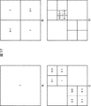
図17にALFブロック分割を最大レイヤ数が3のクアッドツリー構造によって表現し、各ALFブロックにフィルタブロックフラグを指定する例を示す。 FIG. 17 shows an example in which ALF block division is expressed by a quadtree structure with a maximum number of layers of 3, and a filter block flag is designated for each ALF block.
図17Aは、クアッドツリー構造の根になるALFブロックであるレイヤ0を示す。クアッドツリー構造において各ALFブロックは、下位の階層において4分割されるか否かを示すブロックパーティショニングフラグを有している。図17Aに示されるALFブロックのブロックパーティショニングフラグの値は「1」である。つまり、このALFブロックは、下位の階層(レイヤ1)において4分割される。図17Bは、そのレイヤ1を示す。すなわち、レイヤ1には、4つのALFブロックが形成される。
FIG. 17A shows
ブロックパーティショニングフラグが「0」の場合、これより下位の階層において4分割されない。すなわち、これ以上の分割は無く、そのALFブロックに対してフィルタブロックフラグが生成される。つまり、ブロックパーティショニングフラグが「0」のALFブロックは、フィルタブロックフラグも有する。図17Bに示される「0−1」の左の「0」が、そのALFブロックのブロックパーティショニングフラグを示し、右の「1」が、そのALFブロックのフィルタブロックフラグを示す。 When the block partitioning flag is “0”, it is not divided into four in lower layers. That is, there is no further division, and a filter block flag is generated for the ALF block. That is, the ALF block whose block partitioning flag is “0” also has a filter block flag. “0” on the left of “0-1” shown in FIG. 17B indicates the block partitioning flag of the ALF block, and “1” on the right indicates the filter block flag of the ALF block.
レイヤ1のブロックパーティショニングフラグが「1」の2つのALFブロックは、さらに下位の階層(レイヤ2)において4分割される。図17Cは、そのレイヤ2を示す。すなわち、レイヤ2には、10個のALFブロックが形成される。
Two ALF blocks whose layer partitioning flag of
同様に、レイヤ2においてブロックパーティショニングフラグが「0」のALFブロックには、フィルタブロックフラグも割り当てられる。図17Cにおいては、1つのALFブロックのブロックパーティショニングフラグが「1」である。つまり、そのALFブロックは、さらに下位の階層(レイヤ3)において4分割される。図17Dは、そのレイヤ3を示す。すなわち、レイヤ3には、13個のALFブロックが形成される。 Similarly, a filter block flag is also assigned to an ALF block whose block partitioning flag is “0” in layer 2. In FIG. 17C, the block partitioning flag of one ALF block is “1”. That is, the ALF block is divided into four in the lower hierarchy (layer 3). FIG. 17D shows the layer 3. That is, 13 ALF blocks are formed in layer 3.
図17のようにクアッドツリー化することにより、ALFブロックの構成は、最終的に図18に示されるようになる。このように、クアッドツリー構造においては、ALFブロックのサイズは、その階層毎に異なる。つまり、ALFブロックは、クアッドツリー構造をとることにより、フレーム内においてその大きさを互いに異なるものとすることができる。 By forming a quad tree as shown in FIG. 17, the configuration of the ALF block finally becomes as shown in FIG. As described above, in the quadtree structure, the size of the ALF block is different for each hierarchy. That is, ALF blocks can have different sizes within a frame by adopting a quadtree structure.
各ALFブロックにおけるフィルタブロックフラグの制御は、第1の実施の形態の場合と同様である。つまり、フィルタブロックフラグの値が「0」のALFブロックの領域(図18の斜線模様部分)は、フィルタ処理が行われない。 Control of the filter block flag in each ALF block is the same as in the case of the first embodiment. That is, the filter process is not performed on the area of the ALF block (the hatched portion in FIG. 18) whose filter block flag value is “0”.
マルチスライスの場合に符号化効率が低減する恐れがあるという問題は、フレームよりも小さいスライス領域でALFブロックを設定する際に発生するため、ALFブロックの表現を改良したQALFでも同じ問題が生じる。 The problem that the coding efficiency may be reduced in the case of multi-slice occurs when an ALF block is set in a slice area smaller than a frame. Therefore, the same problem occurs in QALF in which the expression of the ALF block is improved.
図19は、図5のスライス1の領域をQALFの技術を使って符号化する例を示している。ここで太線421の領域はスライス1の領域を示す。第1の実施の形態において説明したBALFの場合と同様に、図19の場合も、斜線模様で示されるALFブロックは、スライス1の領域を含んでいないため不要なALFブロックとなる。
FIG. 19 shows an example in which the area of
従来のように、この不要なALFブロックにもフィルタブロックフラグを与えると画像圧縮情報を不要に増大させることになり、符号化効率を悪化させる恐れがある。 If the filter block flag is also given to this unnecessary ALF block as in the prior art, the image compression information is unnecessarily increased, which may deteriorate the coding efficiency.
画像符号化装置100は、QALFの場合も、第1の実施の形態において説明したBALFの場合と同様の方法により、不要なフィルタブロックフラグの生成を抑制し、スライスヘッダに含めないようにすることができる。 In the case of QALF, the image coding apparatus 100 suppresses the generation of unnecessary filter block flags by the same method as in the case of BALF described in the first embodiment so that it is not included in the slice header. Can do.
つまり、画像符号化装置100と画像復号装置200は、図19に示される斜線模様のブロックが当該スライス(図19ではスライス1)を含まないことを認識可能である。そこで、画像符号化装置100が、当該スライスを含む、クアッドツリー構造のALFブロックについてのみフィルタブロックフラグを生成して画像圧縮情報とともに画像復号装置200に供給するようにすることで、不要なフィルタブロックフラグの発生を抑制し、符号化効率の低下を抑制することができる。
That is, the image encoding device 100 and the image decoding device 200 can recognize that the block with the hatched pattern shown in FIG. 19 does not include the slice (
<5.第5の実施の形態>
[パーソナルコンピュータ]
上述した一連の処理は、ハードウエアにより実行させることもできるし、ソフトウエアにより実行させることもできる。この場合、例えば、図20に示されるようなパーソナルコンピュータとして構成されるようにしてもよい。
<5. Fifth embodiment>
[Personal computer]
The series of processes described above can be executed by hardware or can be executed by software. In this case, for example, a personal computer as shown in FIG. 20 may be configured.
図20において、パーソナルコンピュータ500のCPU501は、ROM(Read Only Memory)502に記憶されているプログラム、または記憶部513からRAM(Random Access Memory)503にロードされたプログラムに従って各種の処理を実行する。RAM503にはまた、CPU501が各種の処理を実行する上において必要なデータなども適宜記憶される。
20, the
CPU501、ROM502、およびRAM503は、バス504を介して相互に接続されている。このバス504にはまた、入出力インタフェース510も接続されている。
The
入出力インタフェース510には、キーボード、マウスなどよりなる入力部511、CRT(Cathode Ray Tube)やLCD(Liquid Crystal Display)などよりなるディスプレイ、並びにスピーカなどよりなる出力部512、ハードディスクなどより構成される記憶部513、モデムなどより構成される通信部514が接続されている。通信部514は、インターネットを含むネットワークを介しての通信処理を行う。
The input /
入出力インタフェース510にはまた、必要に応じてドライブ515が接続され、磁気ディスク、光ディスク、光磁気ディスク、或いは半導体メモリなどのリムーバブルメディア521が適宜装着され、それらから読み出されたコンピュータプログラムが、必要に応じて記憶部513にインストールされる。
A
上述した一連の処理をソフトウエアにより実行させる場合には、そのソフトウエアを構成するプログラムが、ネットワークや記録媒体からインストールされる。 When the above-described series of processing is executed by software, a program constituting the software is installed from a network or a recording medium.
この記録媒体は、例えば、図20に示されるように、装置本体とは別に、ユーザにプログラムを配信するために配布される、プログラムが記録されている磁気ディスク(フレキシブルディスクを含む)、光ディスク(CD-ROM(Compact Disc - Read Only Memory),DVD(Digital Versatile Disc)を含む)、光磁気ディスク(MD(Mini Disc)を含む)、もしくは半導体メモリなどよりなるリムーバブルメディア521により構成されるだけでなく、装置本体に予め組み込まれた状態でユーザに配信される、プログラムが記録されているROM502や、記憶部513に含まれるハードディスクなどで構成される。
For example, as shown in FIG. 20, the recording medium is distributed to distribute the program to the user separately from the apparatus main body, and includes a magnetic disk (including a flexible disk) on which the program is recorded, an optical disk ( It only consists of
なお、コンピュータが実行するプログラムは、本明細書で説明する順序に沿って時系列に処理が行われるプログラムであっても良いし、並列に、あるいは呼び出しが行われたとき等の必要なタイミングで処理が行われるプログラムであっても良い。 The program executed by the computer may be a program that is processed in time series in the order described in this specification, or in parallel or at a necessary timing such as when a call is made. It may be a program for processing.
また、本明細書において、記録媒体に記録されるプログラムを記述するステップは、記載された順序に沿って時系列的に行われる処理はもちろん、必ずしも時系列的に処理されなくとも、並列的あるいは個別に実行される処理をも含むものである。 Further, in the present specification, the step of describing the program recorded on the recording medium is not limited to the processing performed in chronological order according to the described order, but may be performed in parallel or It also includes processes that are executed individually.
また、本明細書において、システムとは、複数のデバイス(装置)により構成される装置全体を表すものである。 Further, in this specification, the system represents the entire apparatus composed of a plurality of devices (apparatuses).
また、以上において、1つの装置(または処理部)として説明した構成を分割し、複数の装置(または処理部)として構成するようにしてもよい。逆に、以上において複数の装置(または処理部)として説明した構成をまとめて1つの装置(または処理部)として構成されるようにしてもよい。また、各装置(または各処理部)の構成に上述した以外の構成を付加するようにしてももちろんよい。さらに、システム全体としての構成や動作が実質的に同じであれば、ある装置(または処理部)の構成の一部を他の装置(または他の処理部)の構成に含めるようにしてもよい。つまり、本発明の実施の形態は、上述した実施の形態に限定されるものではなく、本発明の要旨を逸脱しない範囲において種々の変更が可能である。 In addition, in the above description, the configuration described as one device (or processing unit) may be divided and configured as a plurality of devices (or processing units). Conversely, the configurations described above as a plurality of devices (or processing units) may be combined into a single device (or processing unit). Of course, a configuration other than that described above may be added to the configuration of each device (or each processing unit). Furthermore, if the configuration and operation of the entire system are substantially the same, a part of the configuration of a certain device (or processing unit) may be included in the configuration of another device (or other processing unit). . That is, the embodiment of the present invention is not limited to the above-described embodiment, and various modifications can be made without departing from the gist of the present invention.
例えば、上述した画像符号化装置100や画像復号装置200は、任意の電子機器に適用することができる。以下にその例について説明する。 For example, the image encoding device 100 and the image decoding device 200 described above can be applied to any electronic device. Examples thereof will be described below.
<6.第6の実施の形態>
[テレビジョン受像機]
図21は、本発明を適用した画像復号装置200を用いるテレビジョン受像機の主な構成例を示すブロック図である。
<6. Sixth Embodiment>
[Television receiver]
FIG. 21 is a block diagram illustrating a main configuration example of a television receiver using the image decoding device 200 to which the present invention has been applied.
図21に示されるテレビジョン受像機1000は、地上波チューナ1013、ビデオデコーダ1015、映像信号処理回路1018、グラフィック生成回路1019、パネル駆動回路1020、および表示パネル1021を有する。
A
地上波チューナ1013は、地上アナログ放送の放送波信号を、アンテナを介して受信し、復調し、映像信号を取得し、それをビデオデコーダ1015に供給する。ビデオデコーダ1015は、地上波チューナ1013から供給された映像信号に対してデコード処理を施し、得られたデジタルのコンポーネント信号を映像信号処理回路1018に供給する。
The terrestrial tuner 1013 receives a broadcast wave signal of analog terrestrial broadcasting via an antenna, demodulates it, acquires a video signal, and supplies it to the video decoder 1015. The video decoder 1015 performs a decoding process on the video signal supplied from the terrestrial tuner 1013 and supplies the obtained digital component signal to the video
映像信号処理回路1018は、ビデオデコーダ1015から供給された映像データに対してノイズ除去などの所定の処理を施し、得られた映像データをグラフィック生成回路1019に供給する。
The video
グラフィック生成回路1019は、表示パネル1021に表示させる番組の映像データや、ネットワークを介して供給されるアプリケーションに基づく処理による画像データなどを生成し、生成した映像データや画像データをパネル駆動回路1020に供給する。また、グラフィック生成回路1019は、項目の選択などにユーザにより利用される画面を表示するための映像データ(グラフィック)を生成し、それを番組の映像データに重畳したりすることによって得られた映像データをパネル駆動回路1020に供給するといった処理も適宜行う。
The
パネル駆動回路1020は、グラフィック生成回路1019から供給されたデータに基づいて表示パネル1021を駆動し、番組の映像や上述した各種の画面を表示パネル1021に表示させる。
The
表示パネル1021はLCD(Liquid Crystal Display)などよりなり、パネル駆動回路1020による制御に従って番組の映像などを表示させる。
The
また、テレビジョン受像機1000は、音声A/D(Analog/Digital)変換回路1014、音声信号処理回路1022、エコーキャンセル/音声合成回路1023、音声増幅回路1024、およびスピーカ1025も有する。
The
地上波チューナ1013は、受信した放送波信号を復調することにより、映像信号だけでなく音声信号も取得する。地上波チューナ1013は、取得した音声信号を音声A/D変換回路1014に供給する。
The terrestrial tuner 1013 acquires not only the video signal but also the audio signal by demodulating the received broadcast wave signal. The terrestrial tuner 1013 supplies the acquired audio signal to the audio A /
音声A/D変換回路1014は、地上波チューナ1013から供給された音声信号に対してA/D変換処理を施し、得られたデジタルの音声信号を音声信号処理回路1022に供給する。
The audio A /
音声信号処理回路1022は、音声A/D変換回路1014から供給された音声データに対してノイズ除去などの所定の処理を施し、得られた音声データをエコーキャンセル/音声合成回路1023に供給する。
The audio
エコーキャンセル/音声合成回路1023は、音声信号処理回路1022から供給された音声データを音声増幅回路1024に供給する。
The echo cancellation /
音声増幅回路1024は、エコーキャンセル/音声合成回路1023から供給された音声データに対してD/A変換処理、増幅処理を施し、所定の音量に調整した後、音声をスピーカ1025から出力させる。
The
さらに、テレビジョン受像機1000は、デジタルチューナ1016およびMPEGデコーダ1017も有する。
Furthermore, the
デジタルチューナ1016は、デジタル放送(地上デジタル放送、BS(Broadcasting Satellite)/CS(Communications Satellite)デジタル放送)の放送波信号を、アンテナを介して受信し、復調し、MPEG-TS(Moving Picture Experts Group-Transport Stream)を取得し、それをMPEGデコーダ1017に供給する。
The digital tuner 1016 receives a broadcast wave signal of a digital broadcast (terrestrial digital broadcast, BS (Broadcasting Satellite) / CS (Communications Satellite) digital broadcast) via an antenna, demodulates, and MPEG-TS (Moving Picture Experts Group). -Transport Stream) and supply it to the
MPEGデコーダ1017は、デジタルチューナ1016から供給されたMPEG-TSに施されているスクランブルを解除し、再生対象(視聴対象)になっている番組のデータを含むストリームを抽出する。MPEGデコーダ1017は、抽出したストリームを構成する音声パケットをデコードし、得られた音声データを音声信号処理回路1022に供給するとともに、ストリームを構成する映像パケットをデコードし、得られた映像データを映像信号処理回路1018に供給する。また、MPEGデコーダ1017は、MPEG-TSから抽出したEPG(Electronic Program Guide)データを図示せぬ経路を介してCPU1032に供給する。
The
テレビジョン受像機1000は、このように映像パケットをデコードするMPEGデコーダ1017として、上述した画像復号装置200を用いる。なお、放送局等より送信されるMPEG-TSは、画像符号化装置100によって符号化されている。
The
MPEGデコーダ1017は、画像復号装置200の場合と同様に、画像符号化装置100が必要なフィルタブロックフラグのみ含めた画像圧縮情報を適切に復号するので、フィルタ処理の局所的な制御による符号化効率の低減を抑制することができる。例えば、画像の各フレームを複数スライスに分け、スライス毎に符号化された画像圧縮情報に対して、適応フィルタを用いた復号処理を行い、出力する場合においても、符号化効率の低減の抑制が実現可能になる。
As with the image decoding device 200, the
MPEGデコーダ1017から供給された映像データは、ビデオデコーダ1015から供給された映像データの場合と同様に、映像信号処理回路1018において所定の処理が施され、グラフィック生成回路1019において、生成された映像データ等が適宜重畳され、パネル駆動回路1020を介して表示パネル1021に供給され、その画像が表示される。
The video data supplied from the
MPEGデコーダ1017から供給された音声データは、音声A/D変換回路1014から供給された音声データの場合と同様に、音声信号処理回路1022において所定の処理が施され、エコーキャンセル/音声合成回路1023を介して音声増幅回路1024に供給され、D/A変換処理や増幅処理が施される。その結果、所定の音量に調整された音声がスピーカ1025から出力される。
The audio data supplied from the
また、テレビジョン受像機1000は、マイクロホン1026、およびA/D変換回路1027も有する。
The
A/D変換回路1027は、音声会話用のものとしてテレビジョン受像機1000に設けられるマイクロホン1026により取り込まれたユーザの音声の信号を受信し、受信した音声信号に対してA/D変換処理を施し、得られたデジタルの音声データをエコーキャンセル/音声合成回路1023に供給する。
The A /
エコーキャンセル/音声合成回路1023は、テレビジョン受像機1000のユーザ(ユーザA)の音声のデータがA/D変換回路1027から供給されている場合、ユーザAの音声データを対象としてエコーキャンセルを行い、他の音声データと合成するなどして得られた音声のデータを、音声増幅回路1024を介してスピーカ1025より出力させる。
When the audio data of the user (user A) of the
さらに、テレビジョン受像機1000は、音声コーデック1028、内部バス1029、SDRAM(Synchronous Dynamic Random Access Memory)1030、フラッシュメモリ1031、CPU1032、USB(Universal Serial Bus) I/F1033、およびネットワークI/F1034も有する。
The
A/D変換回路1027は、音声会話用のものとしてテレビジョン受像機1000に設けられるマイクロホン1026により取り込まれたユーザの音声の信号を受信し、受信した音声信号に対してA/D変換処理を施し、得られたデジタルの音声データを音声コーデック1028に供給する。
The A /
音声コーデック1028は、A/D変換回路1027から供給された音声データを、ネットワーク経由で送信するための所定のフォーマットのデータに変換し、内部バス1029を介してネットワークI/F1034に供給する。
The
ネットワークI/F1034は、ネットワーク端子1035に装着されたケーブルを介してネットワークに接続される。ネットワークI/F1034は、例えば、そのネットワークに接続される他の装置に対して、音声コーデック1028から供給された音声データを送信する。また、ネットワークI/F1034は、例えば、ネットワークを介して接続される他の装置から送信される音声データを、ネットワーク端子1035を介して受信し、それを、内部バス1029を介して音声コーデック1028に供給する。
The network I /
音声コーデック1028は、ネットワークI/F1034から供給された音声データを所定のフォーマットのデータに変換し、それをエコーキャンセル/音声合成回路1023に供給する。
The
エコーキャンセル/音声合成回路1023は、音声コーデック1028から供給される音声データを対象としてエコーキャンセルを行い、他の音声データと合成するなどして得られた音声のデータを、音声増幅回路1024を介してスピーカ1025より出力させる。
The echo cancellation /
SDRAM1030は、CPU1032が処理を行う上で必要な各種のデータを記憶する。
The
フラッシュメモリ1031は、CPU1032により実行されるプログラムを記憶する。フラッシュメモリ1031に記憶されているプログラムは、テレビジョン受像機1000の起動時などの所定のタイミングでCPU1032により読み出される。フラッシュメモリ1031には、デジタル放送を介して取得されたEPGデータ、ネットワークを介して所定のサーバから取得されたデータなども記憶される。
The
例えば、フラッシュメモリ1031には、CPU1032の制御によりネットワークを介して所定のサーバから取得されたコンテンツデータを含むMPEG-TSが記憶される。フラッシュメモリ1031は、例えばCPU1032の制御により、そのMPEG-TSを、内部バス1029を介してMPEGデコーダ1017に供給する。
For example, the
MPEGデコーダ1017は、デジタルチューナ1016から供給されたMPEG-TSの場合と同様に、そのMPEG-TSを処理する。このようにテレビジョン受像機1000は、映像や音声等よりなるコンテンツデータを、ネットワークを介して受信し、MPEGデコーダ1017を用いてデコードし、その映像を表示させたり、音声を出力させたりすることができる。
The
また、テレビジョン受像機1000は、リモートコントローラ1051から送信される赤外線信号を受光する受光部1037も有する。
The
受光部1037は、リモートコントローラ1051からの赤外線を受光し、復調して得られたユーザ操作の内容を表す制御コードをCPU1032に出力する。
The
CPU1032は、フラッシュメモリ1031に記憶されているプログラムを実行し、受光部1037から供給される制御コードなどに応じてテレビジョン受像機1000の全体の動作を制御する。CPU1032とテレビジョン受像機1000の各部は、図示せぬ経路を介して接続されている。
The
USB I/F1033は、USB端子1036に装着されたUSBケーブルを介して接続される、テレビジョン受像機1000の外部の機器との間でデータの送受信を行う。ネットワークI/F1034は、ネットワーク端子1035に装着されたケーブルを介してネットワークに接続し、ネットワークに接続される各種の装置と音声データ以外のデータの送受信も行う。
The USB I /
テレビジョン受像機1000は、MPEGデコーダ1017として画像復号装置200を用いることにより、画像符号化装置100が必要なフィルタブロックフラグのみ含めた画像圧縮情報を適切に復号することができる。その結果として、テレビジョン受像機1000は、アンテナを介して受信する放送波信号や、ネットワークを介して取得するコンテンツデータの、フィルタ処理の局所的な制御のための符号化効率の低減の抑制を実現させることができる。
By using the image decoding device 200 as the
<7.第7の実施の形態>
[携帯電話機]
図22は、本発明を適用した画像符号化装置および画像復号装置を用いる携帯電話機の主な構成例を示すブロック図である。
<7. Seventh Embodiment>
[Mobile phone]
FIG. 22 is a block diagram illustrating a main configuration example of a mobile phone using the image encoding device and the image decoding device to which the present invention is applied.
図22に示される携帯電話機1100は、各部を統括的に制御するようになされた主制御部1150、電源回路部1151、操作入力制御部1152、画像エンコーダ1153、カメラI/F部1154、LCD制御部1155、画像デコーダ1156、多重分離部1157、記録再生部1162、変復調回路部1158、および音声コーデック1159を有する。これらは、バス1160を介して互いに接続されている。
A cellular phone 1100 shown in FIG. 22 includes a
また、携帯電話機1100は、操作キー1119、CCD(Charge Coupled Devices)カメラ1116、液晶ディスプレイ1118、記憶部1123、送受信回路部1163、アンテナ1114、マイクロホン(マイク)1121、およびスピーカ1117を有する。
The mobile phone 1100 includes an
電源回路部1151は、ユーザの操作により終話および電源キーがオン状態にされると、バッテリパックから各部に対して電力を供給することにより携帯電話機1100を動作可能な状態に起動する。
When the end call and the power key are turned on by the user's operation, the power
携帯電話機1100は、CPU、ROMおよびRAM等でなる主制御部1150の制御に基づいて、音声通話モードやデータ通信モード等の各種モードで、音声信号の送受信、電子メールや画像データの送受信、画像撮影、またはデータ記録等の各種動作を行う。
The mobile phone 1100 transmits and receives voice signals, e-mails and image data, and images in various modes such as a voice call mode and a data communication mode based on the control of the
例えば、音声通話モードにおいて、携帯電話機1100は、マイクロホン(マイク)1121で集音した音声信号を、音声コーデック1159によってデジタル音声データに変換し、これを変復調回路部1158でスペクトラム拡散処理し、送受信回路部1163でデジタルアナログ変換処理および周波数変換処理する。携帯電話機1100は、その変換処理により得られた送信用信号を、アンテナ1114を介して図示しない基地局へ送信する。基地局へ伝送された送信用信号(音声信号)は、公衆電話回線網を介して通話相手の携帯電話機に供給される。
For example, in the voice call mode, the mobile phone 1100 converts the voice signal collected by the microphone (microphone) 1121 into digital voice data by the
また、例えば、音声通話モードにおいて、携帯電話機1100は、アンテナ1114で受信した受信信号を送受信回路部1163で増幅し、さらに周波数変換処理およびアナログデジタル変換処理し、変復調回路部1158でスペクトラム逆拡散処理し、音声コーデック1159によってアナログ音声信号に変換する。携帯電話機1100は、その変換して得られたアナログ音声信号をスピーカ1117から出力する。
Further, for example, in the voice call mode, the cellular phone 1100 amplifies the received signal received by the
更に、例えば、データ通信モードにおいて電子メールを送信する場合、携帯電話機1100は、操作キー1119の操作によって入力された電子メールのテキストデータを、操作入力制御部1152において受け付ける。携帯電話機1100は、そのテキストデータを主制御部1150において処理し、LCD制御部1155を介して、画像として液晶ディスプレイ1118に表示させる。
Further, for example, when transmitting an e-mail in the data communication mode, the mobile phone 1100 receives e-mail text data input by operating the operation key 1119 in the operation
また、携帯電話機1100は、主制御部1150において、操作入力制御部1152が受け付けたテキストデータやユーザ指示等に基づいて電子メールデータを生成する。携帯電話機1100は、その電子メールデータを、変復調回路部1158でスペクトラム拡散処理し、送受信回路部1163でデジタルアナログ変換処理および周波数変換処理する。携帯電話機1100は、その変換処理により得られた送信用信号を、アンテナ1114を介して図示しない基地局へ送信する。基地局へ伝送された送信用信号(電子メール)は、ネットワークおよびメールサーバ等を介して、所定のあて先に供給される。
In addition, the mobile phone 1100 generates e-mail data in the
また、例えば、データ通信モードにおいて電子メールを受信する場合、携帯電話機1100は、基地局から送信された信号を、アンテナ1114を介して送受信回路部1163で受信し、増幅し、さらに周波数変換処理およびアナログデジタル変換処理する。携帯電話機1100は、その受信信号を変復調回路部1158でスペクトラム逆拡散処理して元の電子メールデータを復元する。携帯電話機1100は、復元された電子メールデータを、LCD制御部1155を介して液晶ディスプレイ1118に表示する。
Further, for example, when receiving an e-mail in the data communication mode, the mobile phone 1100 receives and amplifies the signal transmitted from the base station by the transmission /
なお、携帯電話機1100は、受信した電子メールデータを、記録再生部1162を介して、記憶部1123に記録する(記憶させる)ことも可能である。
Note that the mobile phone 1100 can also record (store) the received e-mail data in the
この記憶部1123は、書き換え可能な任意の記憶媒体である。記憶部1123は、例えば、RAMや内蔵型フラッシュメモリ等の半導体メモリであってもよいし、ハードディスクであってもよいし、磁気ディスク、光磁気ディスク、光ディスク、USBメモリ、またはメモリカード等のリムーバブルメディアであってもよい。もちろん、これら以外のものであってもよい。
The
さらに、例えば、データ通信モードにおいて画像データを送信する場合、携帯電話機1100は、撮像によりCCDカメラ1116で画像データを生成する。CCDカメラ1116は、レンズや絞り等の光学デバイスと光電変換素子としてのCCDを有し、被写体を撮像し、受光した光の強度を電気信号に変換し、被写体の画像の画像データを生成する。CCDカメラ1116は、その画像データを、カメラI/F部1154を介して、画像エンコーダ1153で符号化し、符号化画像データに変換する。
Furthermore, for example, when transmitting image data in the data communication mode, the mobile phone 1100 generates image data with the
携帯電話機1100は、このような処理を行う画像エンコーダ1153として、上述した画像符号化装置100を用いる。したがって、画像エンコーダ1053は、画像符号化装置100の場合と同様に、フィルタ処理の局所的な制御による符号化効率の低減を抑制することができる。例えば、画像の各フレームを複数スライスに分け、スライス毎に、適応フィルタを用いた符号化処理を行い、出力する場合においても、画像エンコーダ1053は、符号化効率の低減を抑制することができる。
The cellular phone 1100 uses the above-described image encoding device 100 as the
なお、携帯電話機1100は、このとき同時に、CCDカメラ1116で撮像中にマイクロホン(マイク)1121で集音した音声を、音声コーデック1159においてアナログデジタル変換し、さらに符号化する。
At the same time, the cellular phone 1100 converts the sound collected by the microphone (microphone) 1121 during imaging by the
携帯電話機1100は、多重分離部1157において、画像エンコーダ1153から供給された符号化画像データと、音声コーデック1159から供給されたデジタル音声データとを、所定の方式で多重化する。携帯電話機1100は、その結果得られる多重化データを、変復調回路部1158でスペクトラム拡散処理し、送受信回路部1163でデジタルアナログ変換処理および周波数変換処理する。携帯電話機1100は、その変換処理により得られた送信用信号を、アンテナ1114を介して図示しない基地局へ送信する。基地局へ伝送された送信用信号(画像データ)は、ネットワーク等を介して、通信相手に供給される。
The cellular phone 1100 multiplexes the encoded image data supplied from the
なお、画像データを送信しない場合、携帯電話機1100は、CCDカメラ1116で生成した画像データを、画像エンコーダ1153を介さずに、LCD制御部1155を介して液晶ディスプレイ1118に表示させることもできる。
When image data is not transmitted, the mobile phone 1100 can also display the image data generated by the
また、例えば、データ通信モードにおいて、簡易ホームページ等にリンクされた動画像ファイルのデータを受信する場合、携帯電話機1100は、基地局から送信された信号を、アンテナ1114を介して送受信回路部1163で受信し、増幅し、さらに周波数変換処理およびアナログデジタル変換処理する。携帯電話機1100は、その受信信号を変復調回路部1158でスペクトラム逆拡散処理して元の多重化データを復元する。携帯電話機1100は、多重分離部1157において、その多重化データを分離して、符号化画像データと音声データとに分ける。
Further, for example, when receiving data of a moving image file linked to a simple homepage or the like in the data communication mode, the mobile phone 1100 transmits a signal transmitted from the base station to the transmission /
携帯電話機1100は、画像デコーダ1156において符号化画像データをデコードすることにより、再生動画像データを生成し、これを、LCD制御部1155を介して液晶ディスプレイ1118に表示させる。これにより、例えば、簡易ホームページにリンクされた動画像ファイルに含まれる動画データが液晶ディスプレイ1118に表示される。
The cellular phone 1100 generates reproduced moving image data by decoding the encoded image data in the
携帯電話機1100は、このような処理を行う画像デコーダ1156として、上述した画像復号装置200を用いる。したがって、画像デコーダ1156は、画像復号装置200の場合と同様に、画像符号化装置100が必要なフィルタブロックフラグのみ含めた画像圧縮情報を適切に復号するので、結果としてフィルタ処理の局所的な制御による符号化効率の低減を抑制することができる。例えば、画像の各フレームを複数スライスに分け、スライス毎に符号化された画像圧縮情報に対して、適応フィルタを用いた復号処理を行い、出力する場合においても、符号化効率の低減の抑制が実現可能になる。
The cellular phone 1100 uses the above-described image decoding device 200 as the
このとき、携帯電話機1100は、同時に、音声コーデック1159において、デジタルの音声データをアナログ音声信号に変換し、これをスピーカ1117より出力させる。これにより、例えば、簡易ホームページにリンクされた動画像ファイルに含まれる音声データが再生される。
At this time, the cellular phone 1100 simultaneously converts digital audio data into an analog audio signal in the
なお、電子メールの場合と同様に、携帯電話機1100は、受信した簡易ホームページ等にリンクされたデータを、記録再生部1162を介して、記憶部1123に記録する(記憶させる)ことも可能である。
As in the case of e-mail, the mobile phone 1100 can record (store) the data linked to the received simplified home page in the
また、携帯電話機1100は、主制御部1150において、撮像されてCCDカメラ1116で得られた2次元コードを解析し、2次元コードに記録された情報を取得することができる。
Further, the mobile phone 1100 can analyze the two-dimensional code captured by the
さらに、携帯電話機1100は、赤外線通信部1181で赤外線により外部の機器と通信することができる。
Further, the cellular phone 1100 can communicate with an external device by infrared rays at the
携帯電話機1100は、画像エンコーダ1153として画像符号化装置100を用いることにより、例えばCCDカメラ1116において生成された画像データを符号化して生成する符号化データの、フィルタ処理の局所的な制御による符号化効率の低減を抑制することができる。結果として、携帯電話機1100は、符号化効率のよい符号化データ(画像データ)を、他の装置に提供することができる。
The cellular phone 1100 uses the image encoding device 100 as the
また、携帯電話機1100は、画像デコーダ1156として画像復号装置200を用いることにより、画像符号化装置100が必要なフィルタブロックフラグのみ含めた画像圧縮情報を適切に復号することができる。その結果として、携帯電話機1100は、例えば、簡易ホームページ等にリンクされた動画像ファイルのデータの、フィルタ処理の局所的な制御のための符号化効率の低減を抑制することができる。
Further, by using the image decoding device 200 as the
なお、以上において、携帯電話機1100が、CCDカメラ1116を用いるように説明したが、このCCDカメラ1116の代わりに、CMOS(Complementary Metal Oxide Semiconductor)を用いたイメージセンサ(CMOSイメージセンサ)を用いるようにしてもよい。この場合も、携帯電話機1100は、CCDカメラ1116を用いる場合と同様に、被写体を撮像し、被写体の画像の画像データを生成することができる。
In the above description, the mobile phone 1100 is described as using the
また、以上においては携帯電話機1100として説明したが、例えば、PDA(Personal Digital Assistants)、スマートフォン、UMPC(Ultra Mobile Personal Computer)、ネットブック、ノート型パーソナルコンピュータ等、この携帯電話機1100と同様の撮像機能や通信機能を有する装置であれば、どのような装置であっても携帯電話機1100の場合と同様に、画像符号化装置100および画像復号装置200を適用することができる。 In the above description, the cellular phone 1100 has been described. For example, an imaging function similar to that of the cellular phone 1100 such as a PDA (Personal Digital Assistants), a smartphone, an UMPC (Ultra Mobile Personal Computer), a netbook, a notebook personal computer, or the like. As long as it is a device having a communication function, the image encoding device 100 and the image decoding device 200 can be applied to any device as in the case of the mobile phone 1100.
<8.第8の実施の形態>
[ハードディスクレコーダ]
図23は、本発明を適用した画像符号化装置および画像復号装置を用いるハードディスクレコーダの主な構成例を示すブロック図である。
<8. Eighth Embodiment>
[Hard Disk Recorder]
FIG. 23 is a block diagram illustrating a main configuration example of a hard disk recorder using an image encoding device and an image decoding device to which the present invention is applied.
図23に示されるハードディスクレコーダ(HDDレコーダ)1200は、チューナにより受信された、衛星や地上のアンテナ等より送信される放送波信号(テレビジョン信号)に含まれる放送番組のオーディオデータとビデオデータを、内蔵するハードディスクに保存し、その保存したデータをユーザの指示に応じたタイミングでユーザに提供する装置である。 A hard disk recorder (HDD recorder) 1200 shown in FIG. 23 receives audio data and video data of a broadcast program included in a broadcast wave signal (television signal) transmitted from a satellite or a ground antenna received by a tuner. This is an apparatus for storing in a built-in hard disk and providing the stored data to the user at a timing according to the user's instruction.
ハードディスクレコーダ1200は、例えば、放送波信号よりオーディオデータとビデオデータを抽出し、それらを適宜復号し、内蔵するハードディスクに記憶させることができる。また、ハードディスクレコーダ1200は、例えば、ネットワークを介して他の装置からオーディオデータやビデオデータを取得し、それらを適宜復号し、内蔵するハードディスクに記憶させることもできる。 The hard disk recorder 1200 can extract, for example, audio data and video data from broadcast wave signals, appropriately decode them, and store them in a built-in hard disk. The hard disk recorder 1200 can also acquire audio data and video data from other devices via a network, for example, decode them as appropriate, and store them in a built-in hard disk.
さらに、ハードディスクレコーダ1200は、例えば、内蔵するハードディスクに記録されているオーディオデータやビデオデータを復号してモニタ1260に供給し、モニタ1260の画面にその画像を表示させ、モニタ1260のスピーカよりその音声を出力させることができる。また、ハードディスクレコーダ1200は、例えば、チューナを介して取得された放送波信号より抽出されたオーディオデータとビデオデータ、または、ネットワークを介して他の装置から取得したオーディオデータやビデオデータを復号してモニタ1260に供給し、モニタ1260の画面にその画像を表示させ、モニタ1260のスピーカよりその音声を出力させることもできる。
Further, the hard disk recorder 1200, for example, decodes audio data and video data recorded on the built-in hard disk, supplies them to the
もちろん、この他の動作も可能である。 Of course, other operations are possible.
図23に示されるように、ハードディスクレコーダ1200は、受信部1221、復調部1222、デマルチプレクサ1223、オーディオデコーダ1224、ビデオデコーダ1225、およびレコーダ制御部1226を有する。ハードディスクレコーダ1200は、さらに、EPGデータメモリ1227、プログラムメモリ1228、ワークメモリ1229、ディスプレイコンバータ1230、OSD(On Screen Display)制御部1231、ディスプレイ制御部1232、記録再生部1233、D/Aコンバータ1234、および通信部1235を有する。
As shown in FIG. 23, the hard disk recorder 1200 includes a
また、ディスプレイコンバータ1230は、ビデオエンコーダ1241を有する。記録再生部1233は、エンコーダ1251およびデコーダ1252を有する。
In addition, the
受信部1221は、リモートコントローラ(図示せず)からの赤外線信号を受信し、電気信号に変換してレコーダ制御部1226に出力する。レコーダ制御部1226は、例えば、マイクロプロセッサなどにより構成され、プログラムメモリ1228に記憶されているプログラムに従って、各種の処理を実行する。レコーダ制御部1226は、このとき、ワークメモリ1229を必要に応じて使用する。
The receiving
通信部1235は、ネットワークに接続され、ネットワークを介して他の装置との通信処理を行う。例えば、通信部1235は、レコーダ制御部1226により制御され、チューナ(図示せず)と通信し、主にチューナに対して選局制御信号を出力する。
The communication unit 1235 is connected to a network and performs communication processing with other devices via the network. For example, the communication unit 1235 is controlled by the
復調部1222は、チューナより供給された信号を、復調し、デマルチプレクサ1223に出力する。デマルチプレクサ1223は、復調部1222より供給されたデータを、オーディオデータ、ビデオデータ、およびEPGデータに分離し、それぞれ、オーディオデコーダ1224、ビデオデコーダ1225、またはレコーダ制御部1226に出力する。
The
オーディオデコーダ1224は、入力されたオーディオデータをデコードし、記録再生部1233に出力する。ビデオデコーダ1225は、入力されたビデオデータをデコードし、ディスプレイコンバータ1230に出力する。レコーダ制御部1226は、入力されたEPGデータをEPGデータメモリ1227に供給し、記憶させる。
The
ディスプレイコンバータ1230は、ビデオデコーダ1225またはレコーダ制御部1226より供給されたビデオデータを、ビデオエンコーダ1241により、例えばNTSC(National Television Standards Committee)方式のビデオデータにエンコードし、記録再生部1233に出力する。また、ディスプレイコンバータ1230は、ビデオデコーダ1225またはレコーダ制御部1226より供給されるビデオデータの画面のサイズを、モニタ1260のサイズに対応するサイズに変換し、ビデオエンコーダ1241によってNTSC方式のビデオデータに変換し、アナログ信号に変換し、ディスプレイ制御部1232に出力する。
The
ディスプレイ制御部1232は、レコーダ制御部1226の制御のもと、OSD(On Screen Display)制御部1231が出力したOSD信号を、ディスプレイコンバータ1230より入力されたビデオ信号に重畳し、モニタ1260のディスプレイに出力し、表示させる。
The
モニタ1260にはまた、オーディオデコーダ1224が出力したオーディオデータが、D/Aコンバータ1234によりアナログ信号に変換されて供給されている。モニタ1260は、このオーディオ信号を内蔵するスピーカから出力する。
The
記録再生部1233は、ビデオデータやオーディオデータ等を記録する記憶媒体としてハードディスクを有する。
The recording /
記録再生部1233は、例えば、オーディオデコーダ1224より供給されるオーディオデータを、エンコーダ1251によりエンコードする。また、記録再生部1233は、ディスプレイコンバータ1230のビデオエンコーダ1241より供給されるビデオデータを、エンコーダ1251によりエンコードする。記録再生部1233は、そのオーディオデータの符号化データとビデオデータの符号化データとをマルチプレクサにより合成する。記録再生部1233は、その合成データをチャネルコーディングして増幅し、そのデータを、記録ヘッドを介してハードディスクに書き込む。
For example, the recording / reproducing
記録再生部1233は、再生ヘッドを介してハードディスクに記録されているデータを再生し、増幅し、デマルチプレクサによりオーディオデータとビデオデータに分離する。記録再生部1233は、デコーダ1252によりオーディオデータおよびビデオデータをデコードする。記録再生部1233は、復号したオーディオデータをD/A変換し、モニタ1260のスピーカに出力する。また、記録再生部1233は、復号したビデオデータをD/A変換し、モニタ1260のディスプレイに出力する。
The recording /
レコーダ制御部1226は、受信部1221を介して受信されるリモートコントローラからの赤外線信号により示されるユーザ指示に基づいて、EPGデータメモリ1227から最新のEPGデータを読み出し、それをOSD制御部1231に供給する。OSD制御部1231は、入力されたEPGデータに対応する画像データを発生し、ディスプレイ制御部1232に出力する。ディスプレイ制御部1232は、OSD制御部1231より入力されたビデオデータをモニタ1260のディスプレイに出力し、表示させる。これにより、モニタ1260のディスプレイには、EPG(電子番組ガイド)が表示される。
The
また、ハードディスクレコーダ1200は、インターネット等のネットワークを介して他の装置から供給されるビデオデータ、オーディオデータ、またはEPGデータ等の各種データを取得することができる。 Also, the hard disk recorder 1200 can acquire various data such as video data, audio data, or EPG data supplied from another device via a network such as the Internet.
通信部1235は、レコーダ制御部1226に制御され、ネットワークを介して他の装置から送信されるビデオデータ、オーディオデータ、およびEPGデータ等の符号化データを取得し、それをレコーダ制御部1226に供給する。レコーダ制御部1226は、例えば、取得したビデオデータやオーディオデータの符号化データを記録再生部1233に供給し、ハードディスクに記憶させる。このとき、レコーダ制御部1226および記録再生部1233が、必要に応じて再エンコード等の処理を行うようにしてもよい。
The communication unit 1235 is controlled by the
また、レコーダ制御部1226は、取得したビデオデータやオーディオデータの符号化データを復号し、得られるビデオデータをディスプレイコンバータ1230に供給する。ディスプレイコンバータ1230は、ビデオデコーダ1225から供給されるビデオデータと同様に、レコーダ制御部1226から供給されるビデオデータを処理し、ディスプレイ制御部1232を介してモニタ1260に供給し、その画像を表示させる。
Also, the
また、この画像表示に合わせて、レコーダ制御部1226が、復号したオーディオデータを、D/Aコンバータ1234を介してモニタ1260に供給し、その音声をスピーカから出力させるようにしてもよい。
In accordance with the image display, the
さらに、レコーダ制御部1226は、取得したEPGデータの符号化データを復号し、復号したEPGデータをEPGデータメモリ1227に供給する。
Further, the
以上のようなハードディスクレコーダ1200は、ビデオデコーダ1225、デコーダ1252、およびレコーダ制御部1226に内蔵されるデコーダとして画像復号装置200を用いる。したがって、ビデオデコーダ1225、デコーダ1252、およびレコーダ制御部1226に内蔵されるデコーダは、画像復号装置200の場合と同様に、画像符号化装置100が必要なフィルタブロックフラグのみ含めた画像圧縮情報を適切に復号するので、結果としてフィルタ処理の局所的な制御による符号化効率の低減を抑制することができる。例えば、画像の各フレームを複数スライスに分け、スライス毎に符号化された画像圧縮情報に対して、適応フィルタを用いた復号処理を行い、出力する場合においても、符号化効率の低減の抑制が実現可能になる。
The hard disk recorder 1200 as described above uses the image decoding device 200 as a decoder incorporated in the
したがって、ハードディスクレコーダ1200は、画像符号化装置100が必要なフィルタブロックフラグのみ含めた画像圧縮情報を適切に復号することができる。その結果として、ハードディスクレコーダ1200は、例えば、チューナや通信部1235を介して受信されるビデオデータや、記録再生部1233のハードディスクに記録されるビデオデータの、フィルタ処理の局所的な制御のための符号化効率の低減を抑制することができる。
Therefore, the hard disk recorder 1200 can appropriately decode the image compression information including only the filter block flag necessary for the image encoding device 100. As a result, the hard disk recorder 1200 is used for local control of filter processing of, for example, video data received via the tuner or the communication unit 1235 or video data recorded on the hard disk of the recording /
また、ハードディスクレコーダ1200は、エンコーダ1251として画像符号化装置100を用いる。したがって、エンコーダ1251は、画像符号化装置100の場合と同様に、フィルタ処理の局所的な制御による符号化効率の低減を抑制することができる。例えば、画像の各フレームを複数スライスに分け、スライス毎に、適応フィルタを用いた符号化処理を行い、出力する場合においても、エンコーダ1251は、符号化効率の低減を抑制することができる。 The hard disk recorder 1200 uses the image encoding device 100 as the encoder 1251. Therefore, the encoder 1251 can suppress a reduction in encoding efficiency due to local control of filter processing, as in the case of the image encoding device 100. For example, even when each frame of an image is divided into a plurality of slices and an encoding process using an adaptive filter is performed for each slice and output, the encoder 1251 can suppress a reduction in encoding efficiency.
したがって、ハードディスクレコーダ1200は、例えば、ハードディスクに記録する符号化データの、フィルタ処理の局所的な制御による符号化効率の低減を抑制することができる。その結果として、ハードディスクレコーダ1200は、ハードディスクの記憶領域をより効率よく使用することができる。 Therefore, the hard disk recorder 1200 can suppress, for example, reduction in encoding efficiency due to local control of filter processing of encoded data to be recorded on the hard disk. As a result, the hard disk recorder 1200 can use the storage area of the hard disk more efficiently.
なお、以上においては、ビデオデータやオーディオデータをハードディスクに記録するハードディスクレコーダ1200について説明したが、もちろん、記録媒体はどのようなものであってもよい。例えばフラッシュメモリ、光ディスク、またはビデオテープ等、ハードディスク以外の記録媒体を適用するレコーダであっても、上述したハードディスクレコーダ1200の場合と同様に、画像符号化装置100および画像復号装置200を適用することができる。 In the above description, the hard disk recorder 1200 for recording video data and audio data on the hard disk has been described. Of course, any recording medium may be used. For example, even in a recorder to which a recording medium other than a hard disk such as a flash memory, an optical disk, or a video tape is applied, the image encoding device 100 and the image decoding device 200 are applied as in the case of the hard disk recorder 1200 described above. Can do.
<9.第9の実施の形態>
[カメラ]
図24は、本発明を適用した画像符号化装置および画像復号装置を用いるカメラの主な構成例を示すブロック図である。
<9. Ninth Embodiment>
[camera]
FIG. 24 is a block diagram illustrating a main configuration example of a camera using the image encoding device and the image decoding device to which the present invention is applied.
図24に示されるカメラ1300は、被写体を撮像し、被写体の画像をLCD1316に表示させたり、それを画像データとして、記録メディア1333に記録したりする。
The camera 1300 shown in FIG. 24 images a subject and displays an image of the subject on the
レンズブロック1311は、光(すなわち、被写体の映像)を、CCD/CMOS1312に入射させる。CCD/CMOS1312は、CCDまたはCMOSを用いたイメージセンサであり、受光した光の強度を電気信号に変換し、カメラ信号処理部1313に供給する。
The
カメラ信号処理部1313は、CCD/CMOS1312から供給された電気信号を、Y,Cr,Cbの色差信号に変換し、画像信号処理部1314に供給する。画像信号処理部1314は、コントローラ1321の制御の下、カメラ信号処理部1313から供給された画像信号に対して所定の画像処理を施したり、その画像信号をエンコーダ1341で符号化したりする。画像信号処理部1314は、画像信号を符号化して生成した符号化データを、デコーダ1315に供給する。さらに、画像信号処理部1314は、オンスクリーンディスプレイ(OSD)1320において生成された表示用データを取得し、それをデコーダ1315に供給する。
The camera
以上の処理において、カメラ信号処理部1313は、バス1317を介して接続されるDRAM(Dynamic Random Access Memory)1318を適宜利用し、必要に応じて画像データや、その画像データが符号化された符号化データ等をそのDRAM1318に保持させる。
In the above processing, the camera
デコーダ1315は、画像信号処理部1314から供給された符号化データを復号し、得られた画像データ(復号画像データ)をLCD1316に供給する。また、デコーダ1315は、画像信号処理部1314から供給された表示用データをLCD1316に供給する。LCD1316は、デコーダ1315から供給された復号画像データの画像と表示用データの画像を適宜合成し、その合成画像を表示する。
The
オンスクリーンディスプレイ1320は、コントローラ1321の制御の下、記号、文字、または図形からなるメニュー画面やアイコンなどの表示用データを、バス1317を介して画像信号処理部1314に出力する。
Under the control of the
コントローラ1321は、ユーザが操作部1322を用いて指令した内容を示す信号に基づいて、各種処理を実行するとともに、バス1317を介して、画像信号処理部1314、DRAM1318、外部インタフェース1319、オンスクリーンディスプレイ1320、およびメディアドライブ1323等を制御する。FLASH ROM1324には、コントローラ1321が各種処理を実行する上で必要なプログラムやデータ等が格納される。
The
例えば、コントローラ1321は、画像信号処理部1314やデコーダ1315に代わって、DRAM1318に記憶されている画像データを符号化したり、DRAM1318に記憶されている符号化データを復号したりすることができる。このとき、コントローラ1321は、画像信号処理部1314やデコーダ1315の符号化・復号方式と同様の方式によって符号化・復号処理を行うようにしてもよいし、画像信号処理部1314やデコーダ1315が対応していない方式により符号化・復号処理を行うようにしてもよい。
For example, the
また、例えば、操作部1322から画像印刷の開始が指示された場合、コントローラ1321は、DRAM1318から画像データを読み出し、それを、バス1317を介して外部インタフェース1319に接続されるプリンタ1334に供給して印刷させる。
For example, when the start of image printing is instructed from the
さらに、例えば、操作部1322から画像記録が指示された場合、コントローラ1321は、DRAM1318から符号化データを読み出し、それを、バス1317を介してメディアドライブ1323に装着される記録メディア1333に供給して記憶させる。
Further, for example, when image recording is instructed from the
記録メディア1333は、例えば、磁気ディスク、光磁気ディスク、光ディスク、または半導体メモリ等の、読み書き可能な任意のリムーバブルメディアである。記録メディア1333は、もちろん、リムーバブルメディアとしての種類も任意であり、テープデバイスであってもよいし、ディスクであってもよいし、メモリカードであってもよい。もちろん、非接触ICカード等であっても良い。
The
また、メディアドライブ1323と記録メディア1333を一体化し、例えば、内蔵型ハードディスクドライブやSSD(Solid State Drive)等のように、非可搬性の記憶媒体により構成されるようにしてもよい。
Further, the media drive 1323 and the
外部インタフェース1319は、例えば、USB入出力端子などで構成され、画像の印刷を行う場合に、プリンタ1334と接続される。また、外部インタフェース1319には、必要に応じてドライブ1331が接続され、磁気ディスク、光ディスク、あるいは光磁気ディスクなどのリムーバブルメディア1332が適宜装着され、それらから読み出されたコンピュータプログラムが、必要に応じて、FLASH ROM1324にインストールされる。
The
さらに、外部インタフェース1319は、LANやインターネット等の所定のネットワークに接続されるネットワークインタフェースを有する。コントローラ1321は、例えば、操作部1322からの指示に従って、DRAM1318から符号化データを読み出し、それを外部インタフェース1319から、ネットワークを介して接続される他の装置に供給させることができる。また、コントローラ1321は、ネットワークを介して他の装置から供給される符号化データや画像データを、外部インタフェース1319を介して取得し、それをDRAM1318に保持させたり、画像信号処理部1314に供給したりすることができる。
Furthermore, the
以上のようなカメラ1300は、デコーダ1315として画像復号装置200を用いる。したがって、デコーダ1315は、画像復号装置200の場合と同様に、画像符号化装置100が必要なフィルタブロックフラグのみ含めた画像圧縮情報を適切に復号するので、結果としてフィルタ処理の局所的な制御による符号化効率の低減を抑制することができる。例えば、画像の各フレームを複数スライスに分け、スライス毎に符号化された画像圧縮情報に対して、適応フィルタを用いた復号処理を行い、出力する場合においても、符号化効率の低減の抑制が実現可能になる。
The camera 1300 as described above uses the image decoding device 200 as the
したがって、カメラ1300は、画像符号化装置100が必要なフィルタブロックフラグのみ含めた画像圧縮情報を適切に復号することができる。その結果として、カメラ1300は、例えば、CCD/CMOS1312において生成される画像データや、DRAM1318または記録メディア1333から読み出されるビデオデータの符号化データや、ネットワークを介して取得するビデオデータの符号化データの、フィルタ処理の局所的な制御のための符号化効率の低減を抑制することができる。
Therefore, the camera 1300 can appropriately decode the image compression information including only the filter block flag necessary for the image encoding device 100. As a result, the camera 1300 can, for example, store image data generated in the CCD /
また、カメラ1300は、エンコーダ1341として画像符号化装置100を用いる。したがって、エンコーダ1341は、画像符号化装置100の場合と同様に、フィルタ処理の局所的な制御による符号化効率の低減を抑制することができる。例えば、画像の各フレームを複数スライスに分け、スライス毎に、適応フィルタを用いた符号化処理を行い、出力する場合においても、エンコーダ1341は、符号化効率の低減を抑制することができる。
The camera 1300 uses the image encoding device 100 as the
したがって、カメラ1300は、例えば、DRAM1318や記録メディア1333に記録する符号化データや、他の装置に提供する符号化データの、フィルタ処理の局所的な制御による符号化効率の低減を抑制することができる。その結果として、カメラ1300は、DRAM1318や記録メディア1333の記憶領域をより効率よく使用することができる。また、カメラ1300は、符号化効率のよい符号化データ(画像データ)を、他の装置に提供することもできる。
Therefore, for example, the camera 1300 can suppress a reduction in encoding efficiency due to local control of filter processing of encoded data recorded in the
なお、コントローラ1321が行う復号処理に画像復号装置200の復号方法を適用するようにしてもよい。同様に、コントローラ1321が行う符号化処理に画像符号化装置100の符号化方法を適用するようにしてもよい。
Note that the decoding method of the image decoding device 200 may be applied to the decoding process performed by the
また、カメラ1300が撮像する画像データは動画像であってもよいし、静止画像であってもよい。 The image data captured by the camera 1300 may be a moving image or a still image.
もちろん、画像符号化装置100および画像復号装置200は、上述した装置以外の装置やシステムにも適用可能である。 Of course, the image encoding device 100 and the image decoding device 200 can also be applied to devices and systems other than the devices described above.
また、マクロブロックの大きさも、16×16画素に限らない。例えば図25に示される32×32画素のような、あらゆる大きさのマクロブロックに対して適用することが可能である。 The size of the macroblock is not limited to 16 × 16 pixels. For example, the present invention can be applied to macroblocks of any size such as 32 × 32 pixels shown in FIG.
以上においては、フラグ情報等をビットストリームに多重化(記述)するものとして説明したが、多重化する以外にも、例えば、フラグと画像データ(又はビットストリーム)とを伝送(記録)してもよい。フラグと画像データ(又はビットストリーム)とを連結する(付加する)形態もありうる。 In the above description, the flag information or the like is described as being multiplexed (description) into the bitstream, but in addition to multiplexing, for example, a flag and image data (or bitstream) may be transmitted (recorded). Good. There may be a form in which the flag and the image data (or bit stream) are connected (added).
連結(付加)とは、画像データ(又はビットストリーム)とフラグとが互いにリンクされている状態(対応が取れている状態)を示すものであり、物理的な位置関係は任意である。例えば、画像データ(又はビットストリーム)とフラグとを、別の伝送路で伝送してもよい。また、画像データ(又はビットストリーム)とフラグとを、互いに別の記録媒体(又は同一の記録媒体内の別々の記録エリア)に記録してもよい。なお、画像データ(又はビットストリーム)とフラグとをリンクさせる単位は、任意であり、例えば、符号化処理単位(1フレーム、複数フレーム等)で設定してもよい。 Concatenation (addition) indicates a state in which image data (or bit stream) and a flag are linked to each other (a state in which correspondence is established), and the physical positional relationship is arbitrary. For example, the image data (or bit stream) and the flag may be transmitted through different transmission paths. Further, the image data (or bit stream) and the flag may be recorded on different recording media (or different recording areas in the same recording medium). Note that the unit for linking the image data (or bit stream) and the flag is arbitrary, and may be set, for example, in encoding processing units (one frame, multiple frames, etc.).
100 画像符号化装置, 112 制御情報生成部, 113 適応フィルタ処理部, 132 ブロック情報生成部, 141 処理対象スライス領域特定部, 142 ALFブロック設定部, 143 処理対象ALFブロック領域特定部, 144 判定部, 145 フィルタブロックフラグ生成部, 171 制御部, 172 適応フィルタ, 173 選択部, 200 画像復号装置, 202 可逆復号部, 207 適応フィルタ処理部 DESCRIPTION OF SYMBOLS 100 Image coding apparatus, 112 Control information generation part, 113 Adaptive filter process part, 132 Block information generation part, 141 Processing object slice area | region identification part, 142 ALF block setting part, 143 Processing object ALF block area | region identification part, 144 Determination part , 145 filter block flag generation unit, 171 control unit, 172 adaptive filter, 173 selection unit, 200 image decoding device, 202 lossless decoding unit, 207 adaptive filter processing unit
Claims (4)
前記制御データ生成部により生成された前記制御データにより処理対象の前記画素ブロックに対して前記適応フィルタ処理を行うように指示され、かつ前記サイズデータにより求められる位置における処理対象の前記画素ブロックの画素が処理対象の前記スライスに含まれる場合、処理対象の前記画素ブロックに対して前記適応フィルタ処理を行う適応フィルタ部と、
前記適応フィルタ部により前記制御データに応じて適宜前記適応フィルタ処理が行われた画像データを用いて前記画像データを符号化する符号化部と、
前記符号化部により生成された前記画像データの符号化データと、前記制御データと、前記サイズデータとを伝送する伝送部と
を備える画像符号化装置。 Control data for controlling whether to perform adaptive filter processing for each pixel block having a quad tree structure included in a slice to be processed of image data, and size data representing the size of a quad tree structure pixel block for performing the adaptive filter processing; A control data generation unit for generating
The pixel of the pixel block to be processed at the position that is instructed to perform the adaptive filter processing on the pixel block to be processed by the control data generated by the control data generation unit and is obtained from the size data Is included in the slice to be processed, an adaptive filter unit that performs the adaptive filter processing on the pixel block to be processed;
An encoding unit that encodes the image data using image data that has been appropriately subjected to the adaptive filter processing according to the control data by the adaptive filter unit;
An image encoding device comprising: a transmission unit configured to transmit encoded data of the image data generated by the encoding unit, the control data, and the size data .
生成された前記制御データにより処理対象の前記画素ブロックに対して前記適応フィルタ処理を行うように指示され、かつ前記サイズデータにより求められる位置における処理対象の前記画素ブロックの画素が処理対象の前記スライスに含まれる場合、処理対象の前記画素ブロックに対して前記適応フィルタ処理を行い、
前記制御データに応じて適宜前記適応フィルタ処理が行われた画像データを用いて前記画像データを符号化し、
生成された前記画像データの符号化データと、前記制御データと、前記サイズデータとを伝送する
画像符号化方法。 Control data for controlling whether to perform adaptive filter processing for each pixel block having a quad tree structure included in a slice to be processed of image data, and size data representing the size of a quad tree structure pixel block for performing the adaptive filter processing; Produces
The slice of the pixel block to be processed is instructed to perform the adaptive filter processing on the pixel block to be processed by the generated control data , and the pixel of the pixel block to be processed at the position obtained from the size data The adaptive filter processing is performed on the pixel block to be processed,
The image data is encoded using image data that has been appropriately subjected to the adaptive filter processing according to the control data,
An image encoding method for transmitting encoded data of the generated image data, the control data, and the size data .
画像データの処理対象のスライスに含まれるクアッドツリー構造の画素ブロック毎に適応フィルタ処理を行うかを制御する制御データと、前記適応フィルタ処理を行うクアッドツリー構造の画素ブロックのサイズを表すサイズデータとを生成する制御データ生成部と、
前記制御データ生成部により生成された前記制御データにより処理対象の前記画素ブロックに対して前記適応フィルタ処理を行うように指示され、かつ前記サイズデータにより求められる位置における処理対象の前記画素ブロックの画素が処理対象の前記スライスに含まれる場合、処理対象の前記画素ブロックに対して前記適応フィルタ処理を行う適応フィルタ部と、
前記適応フィルタ部により前記制御データに応じて適宜前記適応フィルタ処理が行われた画像データを用いて前記画像データを符号化する符号化部と、
前記符号化部により生成された前記画像データの符号化データと、前記制御データと、前記サイズデータとを伝送する伝送部と
して機能させるプログラムを記録したコンピュータが読み取り可能な記録媒体。 Computer
Control data for controlling whether to perform adaptive filter processing for each pixel block having a quad tree structure included in a slice to be processed of image data, and size data representing the size of a quad tree structure pixel block for performing the adaptive filter processing; A control data generation unit for generating
The pixel of the pixel block to be processed at the position that is instructed to perform the adaptive filter processing on the pixel block to be processed by the control data generated by the control data generation unit and is obtained from the size data Is included in the slice to be processed, an adaptive filter unit that performs the adaptive filter processing on the pixel block to be processed;
An encoding unit that encodes the image data using image data that has been appropriately subjected to the adaptive filter processing according to the control data by the adaptive filter unit;
A computer-readable recording medium that records a program that functions as a transmission unit that transmits encoded data of the image data generated by the encoding unit, the control data, and the size data .
画像データの処理対象のスライスに含まれるクアッドツリー構造の画素ブロック毎に適応フィルタ処理を行うかを制御する制御データと、前記適応フィルタ処理を行うクアッドツリー構造の画素ブロックのサイズを表すサイズデータとを生成する制御データ生成部と、
前記制御データ生成部により生成された前記制御データにより処理対象の前記画素ブロックに対して前記適応フィルタ処理を行うように指示され、かつ前記サイズデータにより求められる位置における処理対象の前記画素ブロックの画素が処理対象の前記スライスに含まれる場合、処理対象の前記画素ブロックに対して前記適応フィルタ処理を行う適応フィルタ部と、
前記適応フィルタ部により前記制御データに応じて適宜前記適応フィルタ処理が行われた画像データを用いて前記画像データを符号化する符号化部と、
前記符号化部により生成された前記画像データの符号化データと、前記制御データと、前記サイズデータとを伝送する伝送部と
して機能させるプログラム。 Computer
Control data for controlling whether to perform adaptive filter processing for each pixel block having a quad tree structure included in a slice to be processed of image data, and size data representing the size of a quad tree structure pixel block for performing the adaptive filter processing; A control data generation unit for generating
The pixel of the pixel block to be processed at the position that is instructed to perform the adaptive filter processing on the pixel block to be processed by the control data generated by the control data generation unit and is obtained from the size data Is included in the slice to be processed, an adaptive filter unit that performs the adaptive filter processing on the pixel block to be processed;
An encoding unit that encodes the image data using image data that has been appropriately subjected to the adaptive filter processing according to the control data by the adaptive filter unit;
A program that functions as a transmission unit that transmits encoded data of the image data generated by the encoding unit, the control data, and the size data .
Priority Applications (9)
| Application Number | Priority Date | Filing Date | Title |
|---|---|---|---|
| JP2009179394A JP5359657B2 (en) | 2009-07-31 | 2009-07-31 | Image encoding apparatus and method, recording medium, and program |
| US12/820,305 US9215460B2 (en) | 2009-07-31 | 2010-06-22 | Apparatus and method of adaptive block filtering of target slice |
| CN201310654860.2A CN103716626B (en) | 2009-07-31 | 2010-07-21 | Image processing equipment and method |
| CN201010236939.XA CN101990099B (en) | 2009-07-31 | 2010-07-21 | Image processing apparatus and method |
| CN201310654588.8A CN103716625B (en) | 2009-07-31 | 2010-07-21 | Image processing equipment and method |
| US14/032,766 US9210428B2 (en) | 2009-07-31 | 2013-09-20 | Apparatus and method of adaptive block filtering of target slice |
| US14/934,548 US9955161B2 (en) | 2009-07-31 | 2015-11-06 | Apparatus and method of adaptive block filtering of target slice |
| US15/862,222 US10306224B2 (en) | 2009-07-31 | 2018-01-04 | Apparatus and method of adaptive block filtering of target slice based on filter control information |
| US16/299,160 US10841580B2 (en) | 2009-07-31 | 2019-03-12 | Apparatus and method of adaptive block filtering of target slice based on filter control information |
Applications Claiming Priority (1)
| Application Number | Priority Date | Filing Date | Title |
|---|---|---|---|
| JP2009179394A JP5359657B2 (en) | 2009-07-31 | 2009-07-31 | Image encoding apparatus and method, recording medium, and program |
Related Child Applications (1)
| Application Number | Title | Priority Date | Filing Date |
|---|---|---|---|
| JP2013051882A Division JP5573995B2 (en) | 2013-03-14 | 2013-03-14 | Image decoding apparatus and method, recording medium, and program |
Publications (3)
| Publication Number | Publication Date |
|---|---|
| JP2011035619A JP2011035619A (en) | 2011-02-17 |
| JP2011035619A5 JP2011035619A5 (en) | 2012-08-30 |
| JP5359657B2 true JP5359657B2 (en) | 2013-12-04 |
Family
ID=43526965
Family Applications (1)
| Application Number | Title | Priority Date | Filing Date |
|---|---|---|---|
| JP2009179394A Active JP5359657B2 (en) | 2009-07-31 | 2009-07-31 | Image encoding apparatus and method, recording medium, and program |
Country Status (3)
| Country | Link |
|---|---|
| US (5) | US9215460B2 (en) |
| JP (1) | JP5359657B2 (en) |
| CN (3) | CN103716625B (en) |
Families Citing this family (36)
| Publication number | Priority date | Publication date | Assignee | Title |
|---|---|---|---|---|
| US7295609B2 (en) | 2001-11-30 | 2007-11-13 | Sony Corporation | Method and apparatus for coding image information, method and apparatus for decoding image information, method and apparatus for coding and decoding image information, and system of coding and transmitting image information |
| JP5359657B2 (en) | 2009-07-31 | 2013-12-04 | ソニー株式会社 | Image encoding apparatus and method, recording medium, and program |
| JP5344238B2 (en) | 2009-07-31 | 2013-11-20 | ソニー株式会社 | Image encoding apparatus and method, recording medium, and program |
| JP5914962B2 (en) | 2010-04-09 | 2016-05-11 | ソニー株式会社 | Image processing apparatus and method, program, and recording medium |
| US9094658B2 (en) | 2010-05-10 | 2015-07-28 | Mediatek Inc. | Method and apparatus of adaptive loop filtering |
| TWI600318B (en) | 2010-05-18 | 2017-09-21 | Sony Corp | Image processing apparatus and image processing method |
| CN103369320B (en) | 2010-06-04 | 2016-06-22 | 索尼公司 | Image processing equipment and method |
| CN103109531B (en) * | 2010-09-17 | 2016-06-01 | 日本电气株式会社 | Video encoder and video decoding apparatus |
| CA2805722C (en) * | 2010-10-05 | 2016-03-29 | Ching-Yeh Chen | Method and apparatus of region-based adaptive loop filtering |
| BR122020013166B1 (en) | 2010-12-07 | 2021-10-05 | Sony Corporation | IMAGE PROCESSING DEVICE AND METHOD |
| KR101963096B1 (en) | 2010-12-07 | 2019-03-27 | 소니 주식회사 | Image processing device, image processing method and recording medium |
| JP5741076B2 (en) | 2010-12-09 | 2015-07-01 | ソニー株式会社 | Image processing apparatus and image processing method |
| US8630356B2 (en) * | 2011-01-04 | 2014-01-14 | The Chinese University Of Hong Kong | High performance loop filters in video compression |
| KR20190069613A (en) | 2011-02-10 | 2019-06-19 | 벨로스 미디어 인터내셔널 리미티드 | Image processing device and image processing method |
| JP6327435B2 (en) | 2011-03-03 | 2018-05-23 | サン パテント トラスト | Image encoding method, image decoding method, image encoding device, and image decoding device |
| US20120230423A1 (en) * | 2011-03-10 | 2012-09-13 | Esenlik Semih | Line memory reduction for video coding and decoding |
| CN106454381B (en) | 2011-03-11 | 2019-05-28 | 索尼公司 | Image processing apparatus and method |
| TWI530161B (en) | 2011-06-07 | 2016-04-11 | Sony Corp | Image processing apparatus and method |
| RU2608476C2 (en) | 2011-06-28 | 2017-01-18 | Сони Корпорейшн | Image processing apparatus and image processing method |
| JP5907367B2 (en) | 2011-06-28 | 2016-04-26 | ソニー株式会社 | Image processing apparatus and method, program, and recording medium |
| MY193611A (en) * | 2011-07-01 | 2022-10-20 | Samsung Electronics Co Ltd | Method and apparatus for entropy encoding using hierarchical data unit, and method and apparatus for decoding |
| CN103843350A (en) * | 2011-10-14 | 2014-06-04 | 联发科技股份有限公司 | Method and apparatus for loop filtering |
| WO2013053324A1 (en) * | 2011-10-14 | 2013-04-18 | Mediatek Inc. | Method and apparatus for loop filtering |
| JP6034010B2 (en) * | 2011-10-24 | 2016-11-30 | ソニー株式会社 | Encoding apparatus, encoding method, and program |
| US9386305B2 (en) * | 2011-11-28 | 2016-07-05 | Qualcomm Incorporated | Largest coding unit (LCU) or partition-based syntax for adaptive loop filter and sample adaptive offset in video coding |
| US9635359B2 (en) * | 2011-11-28 | 2017-04-25 | Canon Kabushiki Kaisha | Method and apparatus for determining deblocking filter intensity |
| US8792745B2 (en) * | 2011-12-06 | 2014-07-29 | Sony Corporation | Encoder optimization of adaptive loop filters in HEVC |
| WO2014069433A1 (en) * | 2012-11-05 | 2014-05-08 | シャープ株式会社 | Image processing device and image processing method |
| US9554131B1 (en) * | 2013-07-23 | 2017-01-24 | Harmonic, Inc. | Multi-slice/tile encoder with overlapping spatial sections |
| JP2015032916A (en) * | 2013-07-31 | 2015-02-16 | ブラザー工業株式会社 | Program for communication apparatus, and communication apparatus |
| CN104935927A (en) * | 2014-03-17 | 2015-09-23 | 上海京知信息科技有限公司 | HEVC video sequence coding and decoding speed-up method based on assembly line |
| CN105635067B (en) * | 2014-11-04 | 2019-11-15 | 华为技术有限公司 | File transmitting method and device |
| US10057574B2 (en) * | 2015-02-11 | 2018-08-21 | Qualcomm Incorporated | Coding tree unit (CTU) level adaptive loop filter (ALF) |
| US20170102834A1 (en) * | 2015-10-09 | 2017-04-13 | SoukTel, Inc. | Asynchronous survey data collection through mobile devices |
| WO2018022011A1 (en) * | 2016-07-26 | 2018-02-01 | Hewlett-Packard Development Company, L.P. | Indexing voxels for 3d printing |
| CN110089115B (en) * | 2016-08-26 | 2021-07-06 | 夏普株式会社 | Image decoding device and image encoding device |
Family Cites Families (40)
| Publication number | Priority date | Publication date | Assignee | Title |
|---|---|---|---|---|
| JPH06178127A (en) * | 1992-12-04 | 1994-06-24 | Sanyo Electric Co Ltd | Encoder |
| RU2154918C1 (en) * | 1998-08-01 | 2000-08-20 | Самсунг Электроникс Ко., Лтд. | Method and device for loop filtration of image data |
| US7126989B2 (en) * | 2001-09-12 | 2006-10-24 | Matsushita Electric Industrial Co., Ltd. | Image coding method and image decoding method |
| GB2382940A (en) * | 2001-11-27 | 2003-06-11 | Nokia Corp | Encoding objects and background blocks |
| US7295609B2 (en) * | 2001-11-30 | 2007-11-13 | Sony Corporation | Method and apparatus for coding image information, method and apparatus for decoding image information, method and apparatus for coding and decoding image information, and system of coding and transmitting image information |
| WO2004008773A1 (en) * | 2002-07-11 | 2004-01-22 | Matsushita Electric Industrial Co., Ltd. | Filtering intensity decision method, moving picture encoding method, and moving picture decoding method |
| US7127120B2 (en) | 2002-11-01 | 2006-10-24 | Microsoft Corporation | Systems and methods for automatically editing a video |
| HUP0301368A3 (en) * | 2003-05-20 | 2005-09-28 | Amt Advanced Multimedia Techno | Method and equipment for compressing motion picture data |
| JP2005123732A (en) | 2003-10-14 | 2005-05-12 | Matsushita Electric Ind Co Ltd | Apparatus and method for deblocking filter processing |
| JP4533081B2 (en) * | 2004-10-12 | 2010-08-25 | キヤノン株式会社 | Image encoding apparatus and method |
| CN100345450C (en) * | 2005-01-31 | 2007-10-24 | 浙江大学 | Deblocking filtering method and apparatus of video frequency or image |
| CN100488253C (en) * | 2005-02-07 | 2009-05-13 | 上海芯华微电子有限公司 | Decoding method and decoder for video code flow crossing multiple strip bands |
| JP4475196B2 (en) * | 2005-07-21 | 2010-06-09 | 日本ビクター株式会社 | Block noise detection device and block noise detection program |
| CN100435588C (en) * | 2005-09-23 | 2008-11-19 | 逐点半导体(上海)有限公司 | Block effect removing method for video compression |
| JP4649355B2 (en) * | 2006-03-27 | 2011-03-09 | 富士通株式会社 | Block noise detection method and apparatus, and block noise reduction method and apparatus |
| CN101150719B (en) * | 2006-09-20 | 2010-08-11 | 华为技术有限公司 | Parallel video coding method and device |
| JP2008182562A (en) * | 2007-01-25 | 2008-08-07 | Matsushita Electric Ind Co Ltd | Method and device of adaptive deblocking filtering using quantization matrix |
| CN100512442C (en) * | 2007-04-20 | 2009-07-08 | 西安交通大学 | Method of adaptive motion compensation time-domain filter |
| US20090154567A1 (en) | 2007-12-13 | 2009-06-18 | Shaw-Min Lei | In-loop fidelity enhancement for video compression |
| EP2229782A2 (en) * | 2008-01-14 | 2010-09-22 | Thomson Licensing | Methods and apparatus for de-artifact filtering using multi-lattice sparsity-based filtering |
| MX2010009194A (en) * | 2008-03-07 | 2010-09-10 | Toshiba Kk | Dynamic image encoding/decoding method and device. |
| US20090304086A1 (en) * | 2008-06-06 | 2009-12-10 | Apple Inc. | Method and system for video coder and decoder joint optimization |
| US8634456B2 (en) * | 2008-10-03 | 2014-01-21 | Qualcomm Incorporated | Video coding with large macroblocks |
| KR101647376B1 (en) * | 2009-03-30 | 2016-08-10 | 엘지전자 주식회사 | A method and an apparatus for processing a video signal |
| EP2262267A1 (en) * | 2009-06-10 | 2010-12-15 | Panasonic Corporation | Filter coefficient coding scheme for video coding |
| KR20110001990A (en) * | 2009-06-30 | 2011-01-06 | 삼성전자주식회사 | Apparatus and metohd of in loop filtering an image data and encoding/decoding apparatus using the same |
| JP5359657B2 (en) * | 2009-07-31 | 2013-12-04 | ソニー株式会社 | Image encoding apparatus and method, recording medium, and program |
| JP5344238B2 (en) * | 2009-07-31 | 2013-11-20 | ソニー株式会社 | Image encoding apparatus and method, recording medium, and program |
| JP5233897B2 (en) | 2009-07-31 | 2013-07-10 | ソニー株式会社 | Image processing apparatus and method |
| JP5914962B2 (en) * | 2010-04-09 | 2016-05-11 | ソニー株式会社 | Image processing apparatus and method, program, and recording medium |
| TWI600318B (en) * | 2010-05-18 | 2017-09-21 | Sony Corp | Image processing apparatus and image processing method |
| CN103369320B (en) * | 2010-06-04 | 2016-06-22 | 索尼公司 | Image processing equipment and method |
| KR101963096B1 (en) * | 2010-12-07 | 2019-03-27 | 소니 주식회사 | Image processing device, image processing method and recording medium |
| BR122020013166B1 (en) * | 2010-12-07 | 2021-10-05 | Sony Corporation | IMAGE PROCESSING DEVICE AND METHOD |
| JP5741076B2 (en) * | 2010-12-09 | 2015-07-01 | ソニー株式会社 | Image processing apparatus and image processing method |
| KR20190069613A (en) * | 2011-02-10 | 2019-06-19 | 벨로스 미디어 인터내셔널 리미티드 | Image processing device and image processing method |
| CN106454381B (en) * | 2011-03-11 | 2019-05-28 | 索尼公司 | Image processing apparatus and method |
| TWI530161B (en) * | 2011-06-07 | 2016-04-11 | Sony Corp | Image processing apparatus and method |
| JP5907367B2 (en) * | 2011-06-28 | 2016-04-26 | ソニー株式会社 | Image processing apparatus and method, program, and recording medium |
| CN104380752B (en) * | 2012-06-29 | 2018-10-23 | 威勒斯媒体国际有限公司 | Encoding device and coding method |
-
2009
- 2009-07-31 JP JP2009179394A patent/JP5359657B2/en active Active
-
2010
- 2010-06-22 US US12/820,305 patent/US9215460B2/en active Active
- 2010-07-21 CN CN201310654588.8A patent/CN103716625B/en active Active
- 2010-07-21 CN CN201310654860.2A patent/CN103716626B/en active Active
- 2010-07-21 CN CN201010236939.XA patent/CN101990099B/en active Active
-
2013
- 2013-09-20 US US14/032,766 patent/US9210428B2/en active Active
-
2015
- 2015-11-06 US US14/934,548 patent/US9955161B2/en active Active
-
2018
- 2018-01-04 US US15/862,222 patent/US10306224B2/en active Active
-
2019
- 2019-03-12 US US16/299,160 patent/US10841580B2/en active Active
Also Published As
| Publication number | Publication date |
|---|---|
| CN103716625B (en) | 2017-11-07 |
| US20140023150A1 (en) | 2014-01-23 |
| US20110026611A1 (en) | 2011-02-03 |
| US20160065960A1 (en) | 2016-03-03 |
| CN101990099B (en) | 2014-01-08 |
| US20180131935A1 (en) | 2018-05-10 |
| US20190215514A1 (en) | 2019-07-11 |
| US9955161B2 (en) | 2018-04-24 |
| CN103716626B (en) | 2017-11-07 |
| US10306224B2 (en) | 2019-05-28 |
| US9210428B2 (en) | 2015-12-08 |
| CN103716625A (en) | 2014-04-09 |
| JP2011035619A (en) | 2011-02-17 |
| CN101990099A (en) | 2011-03-23 |
| US10841580B2 (en) | 2020-11-17 |
| CN103716626A (en) | 2014-04-09 |
| US9215460B2 (en) | 2015-12-15 |
Similar Documents
| Publication | Publication Date | Title |
|---|---|---|
| JP5359657B2 (en) | Image encoding apparatus and method, recording medium, and program | |
| JP5233897B2 (en) | Image processing apparatus and method | |
| JP5344238B2 (en) | Image encoding apparatus and method, recording medium, and program | |
| JP5604825B2 (en) | Image processing apparatus and method | |
| JP2012147127A (en) | Image processing apparatus and method | |
| JP2018029389A (en) | Image processing apparatus, method, and program | |
| JP6292460B2 (en) | Image processing apparatus and method | |
| JP6137072B2 (en) | Image decoding apparatus and method, recording medium, and program | |
| JP6328076B2 (en) | Image decoding apparatus and method, recording medium, and program | |
| JP2011223357A (en) | Image processing apparatus and method | |
| JP6229770B2 (en) | Image processing apparatus and method, recording medium, and program | |
| JP6620184B2 (en) | Image decoding apparatus, image decoding method, and recording medium | |
| JP6032296B2 (en) | Image processing apparatus and method, recording medium, and program | |
| JP5875565B2 (en) | Image processing apparatus and method, recording medium, and program | |
| JP5573995B2 (en) | Image decoding apparatus and method, recording medium, and program | |
| JP5573997B2 (en) | Image decoding apparatus and method, recording medium, and program | |
| JP5573996B2 (en) | Image encoding apparatus and method, recording medium, and program | |
| JP5429418B2 (en) | Image decoding apparatus and method, recording medium, and program | |
| JP5999773B2 (en) | Image processing apparatus and method, recording medium, and program | |
| JP6241500B2 (en) | Image processing apparatus and method, and program | |
| JP6169056B2 (en) | Image processing apparatus and method, and program | |
| JP2020025345A (en) | Image decoder, image decoding method, and recording medium |
Legal Events
| Date | Code | Title | Description |
|---|---|---|---|
| A521 | Written amendment |
Free format text: JAPANESE INTERMEDIATE CODE: A523 Effective date: 20120713 |
|
| A621 | Written request for application examination |
Free format text: JAPANESE INTERMEDIATE CODE: A621 Effective date: 20120713 |
|
| A977 | Report on retrieval |
Free format text: JAPANESE INTERMEDIATE CODE: A971007 Effective date: 20130218 |
|
| A131 | Notification of reasons for refusal |
Free format text: JAPANESE INTERMEDIATE CODE: A131 Effective date: 20130226 |
|
| A521 | Written amendment |
Free format text: JAPANESE INTERMEDIATE CODE: A523 Effective date: 20130314 |
|
| A131 | Notification of reasons for refusal |
Free format text: JAPANESE INTERMEDIATE CODE: A131 Effective date: 20130409 |
|
| A521 | Written amendment |
Free format text: JAPANESE INTERMEDIATE CODE: A523 Effective date: 20130610 |
|
| TRDD | Decision of grant or rejection written | ||
| A01 | Written decision to grant a patent or to grant a registration (utility model) |
Free format text: JAPANESE INTERMEDIATE CODE: A01 Effective date: 20130806 |
|
| A61 | First payment of annual fees (during grant procedure) |
Free format text: JAPANESE INTERMEDIATE CODE: A61 Effective date: 20130819 |
|
| R151 | Written notification of patent or utility model registration |
Ref document number: 5359657 Country of ref document: JP Free format text: JAPANESE INTERMEDIATE CODE: R151 |
|
| R250 | Receipt of annual fees |
Free format text: JAPANESE INTERMEDIATE CODE: R250 |
|
| R250 | Receipt of annual fees |
Free format text: JAPANESE INTERMEDIATE CODE: R250 |
|
| R250 | Receipt of annual fees |
Free format text: JAPANESE INTERMEDIATE CODE: R250 |
|
| R250 | Receipt of annual fees |
Free format text: JAPANESE INTERMEDIATE CODE: R250 |
|
| R250 | Receipt of annual fees |
Free format text: JAPANESE INTERMEDIATE CODE: R250 |