JP5355409B2 - Sole structure for energy storage and recovery - Google Patents
Sole structure for energy storage and recovery Download PDFInfo
- Publication number
- JP5355409B2 JP5355409B2 JP2009535506A JP2009535506A JP5355409B2 JP 5355409 B2 JP5355409 B2 JP 5355409B2 JP 2009535506 A JP2009535506 A JP 2009535506A JP 2009535506 A JP2009535506 A JP 2009535506A JP 5355409 B2 JP5355409 B2 JP 5355409B2
- Authority
- JP
- Japan
- Prior art keywords
- chamber
- actuator
- sole structure
- region
- elastic membrane
- Prior art date
- Legal status (The legal status is an assumption and is not a legal conclusion. Google has not performed a legal analysis and makes no representation as to the accuracy of the status listed.)
- Active
Links
Images


Classifications
-
- A—HUMAN NECESSITIES
- A43—FOOTWEAR
- A43B—CHARACTERISTIC FEATURES OF FOOTWEAR; PARTS OF FOOTWEAR
- A43B13/00—Soles; Sole-and-heel integral units
- A43B13/14—Soles; Sole-and-heel integral units characterised by the constructive form
- A43B13/18—Resilient soles
-
- A—HUMAN NECESSITIES
- A43—FOOTWEAR
- A43B—CHARACTERISTIC FEATURES OF FOOTWEAR; PARTS OF FOOTWEAR
- A43B13/00—Soles; Sole-and-heel integral units
- A43B13/14—Soles; Sole-and-heel integral units characterised by the constructive form
- A43B13/18—Resilient soles
- A43B13/181—Resiliency achieved by the structure of the sole
-
- A—HUMAN NECESSITIES
- A43—FOOTWEAR
- A43B—CHARACTERISTIC FEATURES OF FOOTWEAR; PARTS OF FOOTWEAR
- A43B13/00—Soles; Sole-and-heel integral units
- A43B13/14—Soles; Sole-and-heel integral units characterised by the constructive form
-
- A—HUMAN NECESSITIES
- A43—FOOTWEAR
- A43B—CHARACTERISTIC FEATURES OF FOOTWEAR; PARTS OF FOOTWEAR
- A43B21/00—Heels; Top-pieces or top-lifts
- A43B21/24—Heels; Top-pieces or top-lifts characterised by the constructive form
- A43B21/26—Resilient heels
Landscapes
- Footwear And Its Accessory, Manufacturing Method And Apparatuses (AREA)
Abstract
Description
[関連出願の相互参照]
本出願は、2006年11月6日付けで提出された米国仮出願番号第60/857,089号の優先権を主張し、その全体が、参照によって本出願に組み込まれる。
[Cross-reference of related applications]
This application claims priority from US Provisional Application No. 60 / 857,089, filed November 6, 2006, which is incorporated by reference in its entirety.
本出願は、一般的に履物の物品に関して、より特に、人間によって発生した運動エネルギーを蓄積するために、運動用履物内に組み込まれる、又は現存する履物及び同様のもの内のインサートとして組み込まれることができるソール構造に関する。ソール構造は、構造的な特徴の組み合わせを有し、該特徴の組み合わせは、レクリエーション活動及びスポーツ活動において当事者の性能を補足し、且つ増大する、着用者の筋力エネルギーの増強された蓄積、回復、及び誘導を可能にする。 This application generally relates to footwear articles, and more particularly to be incorporated into athletic footwear or as an insert within existing footwear and the like to store kinetic energy generated by humans. It is related with the sole structure which can do. The sole structure has a combination of structural features, the combination of features supplementing and increasing the performance of the party in recreational and sports activities, enhanced accumulation, recovery of the wearer's muscular energy, And allow guidance.
従来のウォーキング及びランニングの歩行において、一の足は、スタンスモードにおける(地面などの)支持表面に接触する一方、他の足は、スィングモードにおける空気を通じて移動する。スタンスモード中に、支持表面と接触する足は、3つの連続的な基本的なフェーズ、すなわちヒールストライクフェーズ(heel strike)、ミッドスタンスフェーズ(mid stance)、及びトーオフフェーズ(toe off)を通じて移動する。ヒールストライクフェーズは、より速いペースのランニング、及び好ましいランニングフォームととともに排除される。 In conventional walking and running gait, one foot contacts a support surface (such as the ground) in stance mode while the other foot moves through the air in swing mode. During stance mode, the foot in contact with the support surface moves through three successive basic phases: a heel strike phase, a mid stance phase, and a toe off phase. To do. The heel strike phase is eliminated with faster paced running and the preferred running form.
ランニングシューズの設計者は、走者の足を保護するために十分なクッションを提供することと、走者の足がぐらつき、膝及び下半身の働きが位置合わせされる状態で、同調しないように十分でないクッションを提供することとの間の妥協点に達しようとする。従来の靴の設計は、スタンスモードの各段階中に、走者の足及び足首の必要性を適切に扱わず、ある推定によれば、少なくとも30%の、足の十分な釣合(proportion)及び足首の機能的な能力の損失が生じ、衝撃を吸収し、筋系及び腱システムに負荷をかけ、走者の身体を前方に推進するためのそれらの能力を含んでいる。 Running shoe designers should provide enough cushioning to protect the runner's feet, and not enough cushioning to keep them out of sync with the runner's feet wobble and the knee and lower body work aligned Try to reach a compromise between providing. Conventional shoe designs do not adequately handle the needs of the runner's feet and ankles during each stage of the stance mode, and according to some estimates, at least 30% of the foot's full proportions and Loss of ankle's functional ability occurs, including their ability to absorb shock, load the muscular and tendon systems, and propel the runner's body forward.
他の困惑している問題は、ランニング、ジャンピング、などの間に発生したエネルギーをどのように蓄積するかである。従来の靴の設計は、衝撃を単に減衰させ、それによって、運動エネルギーを散逸させる。運動エネルギーを失うというよりむしろ、そのようなエネルギーを蓄積し、且つ回収することは、有益であると同時に、運動性能を高めるために、はだしのランニングなどのより良い足の感覚認知を可能にする。しかしながら、従来の靴の構造は、この必要性を扱うことができない。 Another perplexing problem is how to store the energy generated during running, jumping, etc. Conventional shoe designs simply dampen the impact, thereby dissipating kinetic energy. Rather than losing kinetic energy, it is beneficial to store and recover such energy, while at the same time enabling better foot sensory perception, such as barefoot running, to improve motor performance To do. However, conventional shoe constructions cannot address this need.
それ故に、十分なクッション性、適切な安定支持、走者の性能を補足し、且つ増大する方法で、走者のエネルギーの増強された蓄積、回復、及び誘導を提供するであろう靴用のソールの必要性が存在する。 Therefore, the sole of a shoe sole that will provide enhanced storage, recovery, and guidance of the runner's energy in a manner that complements and increases the cushioning, adequate stability support, and the runner's performance. There is a need.
この出願は、特定の実施形態において、圧縮の重量がその上に配置される場合にエネルギーを蓄積し、重量が取り去られる場合に、そのエネルギーを解放するソール構造に関する。ソール構造は、ソール構造が、着用者の足のかかと領域、中足領域、及びつま先領域の下あるように、靴の上部の下にある全体的な構造を備えることができ、又はソールの正しい部分を備えることができる。ソール構造は、所望される性質を提供するために、様々な組み合わせで以下に記載される1つ又は複数の実施形態を備える。本明細書に記載されるように、製造中に組み込まれた、又はインサートとして使用される、1つ又は複数のソール構造を使用する靴は、本出願の技術的範囲内にあるので、熟慮される。 This application relates in certain embodiments to a sole structure that stores energy when a weight of compression is placed thereon and releases that energy when the weight is removed. The sole structure can comprise an overall structure that is under the upper part of the shoe, such that the sole structure is under the heel area, the midfoot area, and the toe area of the wearer's foot, or the correct structure of the sole A portion can be provided. The sole structure comprises one or more embodiments described below in various combinations to provide the desired properties. As described herein, shoes that use one or more sole structures incorporated during manufacture or used as inserts are contemplated as being within the scope of this application. The
一の実施形態において、ヒール領域を緩衝し、ヒール領域を支持し、且つヒール領域にエネルギー回復を提供するためのソール又はソール部分は、基本層と、1つ又は複数のアクチュエータと、その第1の側にアクチュエータによって係合された弾性膜と、弾性膜の第2の側に1つ又は複数のチャンバーを有するヒール層と、を含む。ソールは、基本層の上に剛性トッププレートをさらに含むことができる。基本層は、アクチュエータが基本層からの低減された抵抗とともに作動されることを可能にするように、中央開口部を有することができる。基本層は、1つ又は複数のアクチュエータを受容するための1つ又は複数の凹所を有することができる。例えば、中央アクチュエータは、内側アクチュエータ及び外側アクチュエータとともに使用され、一の実施形態において、弾性膜の上に位置付けられることができる。1つ又は複数のアクチュエータは、僅かにドーム形状の底面を有することができる。弾性膜は、1つ又は複数のアクチュエータによってプレテンション(pretension)されることができる。 In one embodiment, the sole or sole portion for buffering the heel region, supporting the heel region, and providing energy recovery to the heel region includes a base layer, one or more actuators, and a first thereof. And an heel layer having one or more chambers on the second side of the elastic membrane. The sole can further include a rigid top plate over the base layer. The base layer can have a central opening to allow the actuator to be operated with reduced resistance from the base layer. The base layer can have one or more recesses for receiving one or more actuators. For example, the central actuator can be used with the inner and outer actuators and in one embodiment can be positioned over the elastic membrane. The one or more actuators can have a slightly dome-shaped bottom surface. The elastic membrane can be pretensioned by one or more actuators.
一の実施形態において、中足領域を緩衝し、中足領域を支持し、且つ中足領域にエネルギー回復を提供するためのソール又はソール部分は、チャンバーを有する裏当て層の上にある基本層と、チャンバーを覆っている弾性膜と、弾性膜を通じてチャンバーを係合しているアクチュエータと、を含む。チャンバーは、中足領域の下にあり、又は実質的に下にあり、かつ基本層内に画定された少なくとも1部とされる場合がある。ソールは、基本層の上に剛性トッププレートをさらに含むことができる。ソールは、各アクチュエータ内に、又は各アクチュエータと弾性膜との間に配置された剛性化要素をさらに含むことができる。 In one embodiment, the sole or sole portion for buffering the midfoot region, supporting the midfoot region, and providing energy recovery to the midfoot region is a base layer overlying a backing layer having a chamber. And an elastic membrane covering the chamber and an actuator engaging the chamber through the elastic membrane. The chamber may be at least a portion below or substantially below the midfoot region and defined in the base layer. The sole can further include a rigid top plate over the base layer. The sole may further include a stiffening element disposed within each actuator or between each actuator and the elastic membrane.
一の実施形態において、つま先領域を緩衝し、つま先領域を支持し、且つつま先領域にエネルギー回復を提供するためのソールは、チャンバーを有する裏当て層の上にある基本層と、チャンバーを覆っている弾性膜と、弾性膜を通じてチャンバーを係合しているアクチュエータと、を含む。 In one embodiment, a sole for buffering the toe region, supporting the toe region, and providing energy recovery to the toe region includes a base layer overlying a backing layer having a chamber, and covering the chamber. And an actuator engaging the chamber through the elastic membrane.
つま先領域を緩衝し、つま先領域を支持し、且つつま先領域にエネルギー回復を提供するためのソールの他の実施形態は、中足領域からの滑らかな伝達を提供するために構成された略くさび形状のパッドを有する基本層を含む。 Other embodiments of the sole for buffering the toe region, supporting the toe region, and providing energy recovery to the toe region are generally wedge shaped configured to provide smooth transmission from the midfoot region Including a base layer having a plurality of pads.
一の実施形態において、足を緩衝し、足を支持し、且つ足にエネルギー回復を提供するためのソール又はソール部分は、中足領域とつま先領域との間で湾曲領域を含む。 In one embodiment, the sole or sole portion for cushioning the foot, supporting the foot, and providing energy recovery to the foot includes a curved region between the midfoot region and the toe region.
一の実施形態において、足を緩衝し、足を支持し、且つ足にエネルギー回復を提供するためのソール又はソール部分は、他の領域に対して増加された硬さの一の領域を有する可変密度の基本層を含む。 In one embodiment, the sole or sole portion for cushioning the foot, supporting the foot, and providing energy recovery to the foot is variable with one region of increased stiffness relative to other regions. Includes a base layer of density.
一の実施形態において、足を緩衝し、足を支持し、且つ足にエネルギー回復を提供するためのソール構造は、中央凹所及び周辺凹所を画定する基本層を備える。中央アクチュエータは、基本層の中央凹所に位置付けられる。周辺アクチュエータは、基本層の周辺凹所に位置付けられる。弾性膜は、その第1の側で中央アクチュエータ及び周辺アクチュエータによって係合される。ヒール層は、弾性膜の第2の側に複数のチャンバーを有し、前記チャンバーは、中央アクチュエータ及び周辺アクチュエータと垂直方向に位置合わせされている。 In one embodiment, a sole structure for cushioning the foot, supporting the foot, and providing energy recovery to the foot comprises a base layer defining a central recess and a peripheral recess. The central actuator is located in the central recess of the base layer. Peripheral actuators are positioned in the peripheral recesses of the base layer. The elastic membrane is engaged on its first side by a central actuator and a peripheral actuator. The heel layer has a plurality of chambers on the second side of the elastic membrane, the chambers being vertically aligned with the central and peripheral actuators.
一の実施形態において、足の一の領域を緩衝し、足の一の領域を支持し、且つ足の一の領域にエネルギー回復を提供するためのソール構造は、略前後方向に細長くされた、底面に面する複数のチャンバーを画定する基本層を有する。弾性膜は、チャンバーを覆う。複数のアクチュエータは、弾性膜を通じて前記チャンバーを係合する。複数のアクチュエータは、前記略前後方向に細長くされる。 In one embodiment, the sole structure for buffering a region of the foot, supporting the region of the foot, and providing energy recovery for the region of the foot has been elongated in a generally longitudinal direction. Having a base layer defining a plurality of chambers facing the bottom surface; The elastic membrane covers the chamber. A plurality of actuators engage the chamber through an elastic membrane. The plurality of actuators are elongated in the substantially front-rear direction.
一の実施形態において、ソール構造は、少なくとも1つの弾性膜と、少なくとも1つの弾性膜の第1の側に位置付けられた少なくとも1つのチャンバーと、少なくとも1つのチャンバーに対応し、且つ少なくとも1つの弾性膜の第2の側に位置付けられる少なくとも1つのアクチュエータと、を備える。少なくとも1つのアクチュエータ及び少なくとも1つのチャンバーは、少なくとも1つのアクチュエータが少なくとも1つの弾性膜に対して圧縮される場合に、少なくとも1つのチャンバーが少なくとも1つの弾性膜の一部を少なくとも部分的に受容するように、寸法決めされ、且つ位置決めされる。少なくとも1つのチャンバーは、約5mm以上の深さを有する。 In one embodiment, the sole structure corresponds to at least one elastic membrane, at least one chamber positioned on a first side of the at least one elastic membrane, at least one chamber, and at least one elastic At least one actuator positioned on the second side of the membrane. The at least one actuator and the at least one chamber receive at least partially a portion of the at least one elastic membrane when the at least one actuator is compressed against the at least one elastic membrane. As such, it is dimensioned and positioned. At least one chamber has a depth of about 5 mm or more.
一の実施形態において、ソール構造は、少なくとも1つの弾性膜と、少なくとも1つの弾性膜の第1の側に位置付けられた少なくとも1つのチャンバーと、少なくとも1つのチャンバーに対応し、且つ少なくとも1つの弾性膜の第2の側に位置付けられる少なくとも1つのアクチュエータと、を備える。少なくとも1つのアクチュエータは、細長くされ、第1の端部と、第2の端部と、を有する。少なくとも1つのアクチュエータ及び少なくとも1つのチャンバーは、少なくとも1つのアクチュエータが前記少なくとも1つの弾性膜に対して圧縮される場合に、少なくとも1つのチャンバーが少なくとも1つの弾性膜の一部を少なくとも部分的に受容するように、寸法決めされ、且つ位置付けされ、少なくとも1つのアクチュエータの第1の端部は、少なくとも1つのアクチュエータの第2の端部より前に少なくとも1つのチャンバーに入れ、第1の端部は、圧力が使用者の足の一の領域から他の領域へ伝達されるにつれて、第2の端部より前に少なくとも1つのチャンバーから外へ回復する。 In one embodiment, the sole structure corresponds to at least one elastic membrane, at least one chamber positioned on a first side of the at least one elastic membrane, at least one chamber, and at least one elastic At least one actuator positioned on the second side of the membrane. At least one actuator is elongated and has a first end and a second end. The at least one actuator and the at least one chamber at least partially receive a portion of the at least one elastic membrane when the at least one actuator is compressed against the at least one elastic membrane. So that the first end of the at least one actuator is placed in the at least one chamber before the second end of the at least one actuator, the first end being As the pressure is transferred from one region of the user's foot to the other, it recovers out of the at least one chamber prior to the second end.
一の実施形態において、ソール構造は、基本層と、基本層の一部に亘って延在し、且つ少なくとも1つのチャンバーを有する裏当て層と、少なくとも1つの弾性膜と、を備える。基本層及び裏当て層が少なくとも1つの弾性膜の第1の側に位置付けられる。少なくとも1つのアクチュエータは、少なくとも1つのチャンバーに対応し、少なくとも1つの弾性膜の第2の側に位置付けられる。少なくとも1つのアクチュエータ及び少なくとも1つのチャンバーは、少なくとも1つのアクチュエータが少なくとも1つの弾性膜に対して圧縮される場合に、前記少なくとも1つのチャンバーが少なくとも1つの弾性膜の一部を少なくとも部分的に受容するように、寸法決めされ、且つ位置付けられる。 In one embodiment, the sole structure comprises a base layer, a backing layer extending over a portion of the base layer and having at least one chamber, and at least one elastic membrane. A base layer and a backing layer are positioned on the first side of the at least one elastic membrane. At least one actuator corresponds to the at least one chamber and is positioned on the second side of the at least one elastic membrane. At least one actuator and at least one chamber receive at least partially a portion of the at least one elastic membrane when the at least one actuator is compressed against the at least one elastic membrane. To be dimensioned and positioned.
一の実施形態において、ソール構造は、少なくとも1つの弾性膜と、少なくとも1つの弾性膜の第1の側に位置付けられた少なくとも1つのチャンバーと、少なくとも1つのチャンバーに対応し、且つ少なくとも1つのチャンバーの第2の側に位置付けられた少なくとも1つのアクチュエータと、を備える。少なくとも1つのアクチュエータ及び少なくとも1つのチャンバーは、少なくとも1つのアクチュエータが少なくとも1つの弾性膜に対して圧縮される場合に、少なくとも1つのチャンバーが弾性膜の一部を少なくとも部分的に受容するように、寸法決めされ、且つ位置付けられる。前記少なくとも1つのアクチュエータは、前記少なくとも1つの弾性膜を係合し、且つプレテンションする。 In one embodiment, the sole structure corresponds to at least one chamber, at least one chamber positioned on the first side of the at least one elastic membrane, at least one chamber, and at least one chamber. At least one actuator positioned on the second side of the actuator. The at least one actuator and the at least one chamber such that the at least one chamber at least partially receives a portion of the elastic membrane when the at least one actuator is compressed against the at least one elastic membrane; Dimensioned and positioned. The at least one actuator engages and pretensions the at least one elastic membrane.
一の実施形態において、ソール構造は、少なくとも1つの弾性膜と、少なくとも1つの弾性膜の第1の側に位置付けられた中央チャンバー及び1つ又は複数の周辺チャンバーと、中央チャンバー及び1つ又は複数の周辺チャンバーに対応し、且つ少なくとも1つの弾性膜の第2の側に位置付けられる中央アクチュエータ及1つ又は複数の周辺アクチュエータと、を備える。アクチュエータ及びチャンバーは、アクチュエータが少なくとも1つの弾性膜に対して圧縮される場合に、チャンバーが少なくとも1つの弾性膜の一部を少なくとも部分的に受容するように、寸法決めされ、且つ位置付けられる。1つ又は複数の周辺チャンバー及び1つ又は複数の周辺アクチュエータは、中央チャンバー及び中央アクチュエータから離隔して、1つ又は複数の周辺チャンバー及び1つ又は複数の周辺アクチュエータに向けた方向で、足の回転を妨げるように構成される。 In one embodiment, the sole structure includes at least one elastic membrane, a central chamber and one or more peripheral chambers positioned on a first side of the at least one elastic membrane, a central chamber and one or more. A central actuator and one or more peripheral actuators corresponding to the peripheral chambers and positioned on the second side of the at least one elastic membrane. The actuator and chamber are sized and positioned such that the chamber at least partially receives a portion of the at least one elastic membrane when the actuator is compressed against the at least one elastic membrane. The one or more peripheral chambers and the one or more peripheral actuators are spaced apart from the central chamber and the central actuator in a direction toward the one or more peripheral chambers and the one or more peripheral actuators. Configured to prevent rotation.
一の実施形態において、ソールは、少なくとも1つのチャンバーを有し、且つ弾性膜と一体に形成される層を備える。少なくとも1つのチャンバーは、少なくとも1つの弾性膜の第1の側に位置付けられる。少なくとも1つのアクチュエータは、少なくとも1つのチャンバーに対応し、且つ少なくとも1つの弾性膜の第2の側に位置付けられる。少なくとも1つのアクチュエータ及び少なくとも1つのチャンバーは、少なくとも1つのアクチュエータが少なくとも1つの弾性膜に対して圧縮される場合に、少なくとも1つのチャンバーが少なくとも1つの弾性膜の一部を少なくとも部分的に受容するように、寸法決めされ、且つ位置付けられる。 In one embodiment, the sole comprises a layer having at least one chamber and formed integrally with the elastic membrane. At least one chamber is positioned on the first side of the at least one elastic membrane. At least one actuator corresponds to the at least one chamber and is positioned on the second side of the at least one elastic membrane. The at least one actuator and the at least one chamber receive at least partially a portion of the at least one elastic membrane when the at least one actuator is compressed against the at least one elastic membrane. As such, it is dimensioned and positioned.
一の実施形態において、ソール構造は、少なくとも1つの弾性膜と、少なくとも1つのチャンバーを有する基本層と、を備える。少なくとも1つのチャンバーは、少なくとも1つの弾性膜の第1の側に位置付けられる。少なくとも1つのアクチュエータは、少なくとも1つのチャンバーに対応し、少なくとも1つの弾性膜の第2の側に位置付けられる。少なくとも1つのアクチュエータ及び少なくとも1つのチャンバーは、少なくとも1つのアクチュエータが少なくとも1つの弾性膜に対して圧縮される場合に、少なくとも1つのチャンバーが少なくとも1つの弾性膜の一部を少なくとも部分的に受容するように、寸法決めされ、且つ位置付けられる。基本層は、少なくとも1つの上部溝及び少なくとも1つの下部溝を備える湾曲領域を有する。少なくとも1つの上部溝及び少なくとも下部溝は、略外内方法に延在する。 In one embodiment, the sole structure comprises at least one elastic membrane and a base layer having at least one chamber. At least one chamber is positioned on the first side of the at least one elastic membrane. At least one actuator corresponds to the at least one chamber and is positioned on the second side of the at least one elastic membrane. The at least one actuator and the at least one chamber receive at least partially a portion of the at least one elastic membrane when the at least one actuator is compressed against the at least one elastic membrane. As such, it is dimensioned and positioned. The base layer has a curved region with at least one upper groove and at least one lower groove. At least one upper groove and at least the lower groove extend in a generally outer-inner way.
本発明のさらなる目的、特徴、及び利点は、本発明の実施形態の図解的に示される添付された図面と併せて、以下の詳細な説明から明らかになるであろう。 Further objects, features, and advantages of the present invention will become apparent from the following detailed description, taken in conjunction with the accompanying drawings, shown diagrammatically of embodiments of the present invention.
以下に記載された実施形態は、圧縮圧力がソール構造に載置される場合にエネルギーを蓄積し、重量が取り除かれる場合にそのエネルギーを解放するソール構造に関する。いくつかの実施形態は、本明細書に記載された1つ又は複数の実施形態に関連して記載された1つ又は複数の特徴を含むことができる。有益で、本明細書に記載されたソール構造と組み合わされることができる特徴を有しているソール構造は、特許文献1、特許文献2、及び特許文献3、並びに特許文献4に見つけられることができ、それらのそれぞれ全体が参照によって本明細書に組み込まれる。以下の説明において、類似の参照符号は、異なる実施形態における類似の構成要素を示すために使用される。さらに、いくつかの実施形態は、本明細書に記載された1つ又は複数の実施形態に関連して記載された1つ又は複数の特徴を含むことができる。 The embodiments described below relate to a sole structure that accumulates energy when compression pressure is placed on the sole structure and releases that energy when weight is removed. Some embodiments can include one or more features described in connection with one or more embodiments described herein. Sole structures that are useful and have features that can be combined with the sole structures described herein can be found in US Pat. Each of which is incorporated herein by reference in its entirety. In the following description, like reference numerals are used to indicate like components in different embodiments. Further, some embodiments can include one or more features described in connection with one or more embodiments described herein.
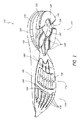
一の実施形態において、ソール110は、図1に示されるように、ヒール領域112と、中足領域114と、つま先領域116と、を含む。図3A及び図3Bを参照して、ヒール領域312は、好ましくは、基本層318と、該基本層の下の、又は基本層内のアクチュエータ320、322、324と、アクチュエータの下の弾性膜326と、弾性膜の下のヒール層328と、ヒール層内に、又はヒール層によって画定されるチャンバー330、332、334と、ヒール層の下の地面係合要素336と、を含む。任意に、トッププレート338は、図3Bに示されるように、基本層上に設けられることができる。ヒール領域は、好ましくは、着用者の足のかかとの幅の全体の下にあり、又は、かかとの幅の略全体の下にある。
In one embodiment, the sole 110 includes a
基本層318は、着用者の足を受容し、且つ着用者の足を支持するように寸法決めされ、且つ構成される上面(図3Bに図示される)を含み、好ましくは、中央開口部340と、凹所342及び344を有することができ、フォーム又は他の弾性材料からなることができる。一の実施形態において、中央開口部340は、中央アクチュエータ320が、基本層318から抵抗を減少させた状態で、中央開口部340内で作動されることを可能にする。外側凹所342及び内側凹所344は、好ましくは、内側アクチュエータ322及び外側アクチュエータ324をそれぞれ受容する。一の実施形態における中央開口部340は、略長楕円形状を有し、外側凹所342及び内側凹所344に開口することができ、外側凹所342及び内側凹所344は、図3Aで示されるように、基本層の側部で開口し、略三角形形状を有することができる。
The
図3A及び図3Bを参照して、中央アクチュエータ320は、かかと骨の下にあり、上面346及び底面348を含む。上面346は、略平坦であることができ、又は、いくつかの実施形態において、湾曲を付けて形成されることができる。底面348は、凸形状又は僅かにドーム形状であることができるが、いくつかの実施形態において、さもなければ、等高で形成される又は平坦とされることができる。一の実施形態において、底面348のドーム形状は、アクチュエータが、下にある表面との骨の相互作用を模擬することを可能にし、それによって足首システムの固有感覚を改善する。一の実施形態において、中央アクチュエータ320は、弾性膜326を係合し、且つ好ましくは、以下に記載されるように、弾性膜326をプレテンションすることができる。
Referring to FIGS. 3A and 3B, the
中央アクチュエータ320及び周辺アクチュエータ322及び324は、製造コストを低減するために、一体型の構成要素として製造されることができるが、中央アクチュエータ320及び周辺アクチュエータ322及び324は、複数の部品からなることもできる。周辺アクチュエータ322及び324は、図3A及び図3Bに図示されるように、各凹所342及び344と一般的に組み合させるために、略三角形状であることができる。好ましくは、中央アクチュエータ及び周辺アクチュエータは、本来の人間の足の幅の略全体的に及ぶ。かかと骨からの圧力の下で、アクチュエータ322及び324は、弾性膜326と係合し、それぞれチャンバー332及び324に移動する。さらに、アクチュエータ322及び324は、弾性膜326にプレテンションすることができる。
The
一の実施形態において、周辺アクチュエータ322及び324は、かかと骨が中央からあまりに遠方に内側へ又は外側へ回転する場合に、さらなる回転を抑制することによって、歩行サイクルの地面係合モード中に、足及び足首に安定性を提供する。例えば、周辺チャンバー332及び334と協働する周辺アクチュエータ322及び324並びに弾性膜326の対応領域は、中央アクチュエータ320、中央チャンバー330、及び弾性膜326の対応領域より広い作動に抵抗することができ、それによって、かかと骨の内側又は外側への回転を妨げるために傾向がある。図3A及び図3Bに示された一の実施形態において、外側アクチュエータ322は、中央アクチュエータ320から前方に配置されることができ、ミッドフットストライク(midfoot strike)中、外側方向で足の過剰な回転を妨げる。内側アクチュエータ324は、中央アクチュエータ320から後方に配置されることができ、ヒールストライク(heel strike)及びミッドスタンス(mid stance)を通じて移動するにつれて、足及び足首に追加の案内を提供する。
In one embodiment, the
いくつかの実施形態において、周辺アクチュエータの数、配置、寸法、及び形状は、上記の説明から変更し、内側の安定性及び外側の安定性に依存し、特定の履物が扱うことを必要とするであろう。1つの周辺アクチュエータより多いアクチュエータは、外側側部又は内側側部のいずれか、又は両方に使用されることができる。例えば、一の実施形態において、ソールは、内側側部に2つのアクチュエータと、外側側部に2つのアクチュエータとを有することができる。 In some embodiments, the number, arrangement, dimensions, and shape of the peripheral actuators vary from the above description and depend on the inner and outer stability and require a particular footwear to handle Will. More than one peripheral actuator can be used on either the outer side or the inner side, or both. For example, in one embodiment, the sole can have two actuators on the inner side and two actuators on the outer side.
弾性膜326は、図3A及び図3Bに示されるように、アクチュエータ320、322、及び324の下にあり、自然の人間の足の全体的な幅又は略全体的な幅に及ぶことができる。弾性膜326はまた、好ましくは、左右方向及び前後方向の両方で、本来の人間のかかとのすべて又は実質的にすべての下にある。弾性膜は、ゴム、合成ゴム、及びデュポン社製のハイトレル(登録商標)などの高弾性の弾性材料及び高弾性の弾性フォームからなることができる。弾性膜326の弾性応答は、そのデュロメーター及び厚さに依存する。好ましい実施形態において、弾性膜326は、デュポン社製のハイトレル(登録商標)で厚さ1.5mmである。
The
弾性膜326は、弾性膜326の中央部分が図6Aで示されるように、ソールが構成される場合に下向きに伸張されるように、中央アクチュエータ320によってプレテンションされることができる。プレテンションは、衝撃に応じて素早い弾性応答を提供するように、ヒールストライクの前に、弾性膜326と中央アクチュエータ320との接触を確実にする。代替案として、又は追加として、周辺アクチュエータは、弾性膜でプレテンションされることができる。いくつかの実施形態において、弾性膜326の厚さは、約0.5mm以下と4mm以上との間の範囲であることができ、1mm、2mm、及び3mmを含む。弾性膜326は、ショアD硬度約320からショアD硬度約45までの硬度の範囲であることができ、ショアD硬度25、35、及び40を含む。硬度及び厚さの選択は、着用者の重量及びチャンバーへのアクチュエータの移動の所望される範囲を含んでいる、靴の特定の適用に依存する。さらに、弾性膜326の厚さは、その長さ及び幅とともに変化することができる。
The
いくつかの実施形態において、弾性膜326は、増加された厚さの領域392を含むことができる。例えば、領域392は、チャンバーの形状及び配置に対応することができ、弾性膜326の他の領域より厚くなることができる。弾性膜326の厚くされた領域392は、均一の厚さ、又は領域の長さ又は横幅、又は両方とともに変化することができる厚さのいずれか、であることができる。
In some embodiments, the
一の実施形態において、弾性膜326及びヒール層328は、図3A及び図3Bに示されるように、別個の部材である。弾性膜326は、弾性膜326が伸張されると、周囲の移動に抵抗するために、弾性膜326の周囲の周りに延在するリムを含むことができる。このリムは、ヒール層を囲む弾性膜の下向きに延在する壁又は厚くされた周囲、又は基本層を囲む上向きに延在する壁又は厚くされた周囲、又は両方を含むことができる。図4A及び図4Bに示される他の実施形態において、弾性膜426及びヒール層428は、ショアC硬度約50以下からショアC硬度約65以上の硬さを有することができる高い応答性のエラストマーフォーム及びEVAを使用して一体に形成されることができる。弾性膜426を備えている領域は、約1mm以下から約3mm以上の厚さの範囲であることができる。他の実施形態において、弾性膜526は、2つの別個の部分を備えることができ、図5A及び図5Bで一の実施形態に従って示されるような、周辺チャンバー532及び534などの1つ又は複数のチャンバーを覆っている第1の部分であって、ヒール層と一体に形成されることができる第1の部分と、中央チャンバー530などの1つ又は複数の他のチャンバーを覆うことができる弾性膜526の第2の部分と、を備えることができる。
In one embodiment, the
図3A及び図3Bを再び参照して、ヒール層328は、1つ又は複数の部品を備え、フォーム又は他の弾性材料からなることができる。一の実施形態において、ヒール層328は、EVAフォームからなる。いくつかの実施形態において、ヒール層328の硬さは、ショアC硬度約50以下からショアC硬度約70以上までの範囲であり、ショアC硬度55、60、及び65を含むことができる。いくつかの実施形態において、ヒール層328の硬さは、基本層318の硬さと略等しい場合がある。他の実施形態において、ヒール層328は、基本層318より硬い、又はより軟らかい場合もある。一の好ましい実施形態において、ヒール層328は、ショアC硬度約65の硬さを有する一方、基本層318は、ショアC硬度約58の硬さを有する。
Referring again to FIGS. 3A and 3B, the
ヒール層328は、略環状形状を有することができ、且つ中央チャンバー330並びに周辺チャンバー332及び334を提供することができる。チャンバー330、332、及び334は、弾性膜326が、アクチュエータ320、322、及び324によって移動される場合に、チャンバー330、332、及び334を入れるように、弾性膜326に隣接して配置されることができる。重量を低減するために、チャンバー330、332、及び334は、底部に開口する。しかしながら、いくつかの実施形態において、チャンバー330、332、334は、底部に近接される場合がある。ヒール層は、好ましくは、着用者のかかとの幅の全体又は幅の略全体に及ぶ。
The
中央チャンバー330は、周辺チャンバー332及び334が略三角形状であり、かつ側部に開口する状態で、一の実施形態で略長楕円形状を有することができる。圧力がヒール領域312に適用されるにつれて、1つ又は複数のアクチュエータ320、322、及び324は、好ましくは、弾性膜326を移動させる。足が前方に移動するにつれて、圧力は、ヒール領域312から解放され、弾性膜326は、好ましくは、そのオリジナル位置に戻って回復するために十分な弾力性を有する。
The
図3Bに示されるように、トッププレート338は、好ましくは、基本層318の上に配置される。図示されるように、中央アクチュエータ320は、基本層の上面を通じて可視することができるのに対し、周辺アクチュエータ322及び324は、基本層の材料によって周辺アクチュエータ322及び324の上面に沿って覆われることができる。トッププレート338は、炭素繊維、熱可塑性ウレタン(TPU)又は、他の剛性を有するが、可撓性である材料、又は低剛性であり、伸張可能な材料からなることができる。比較的に剛性を有する材料は、伸張を強制することによってエネルギー回復及び一歩一歩進んでいくためのエネルギー回復を改善するために使用されることができ、低剛性を有し、伸張可能な材料がクッションを改善するために使用されることができる。他の実施形態において、トッププレート338は、重量を低減するために省略される場合がある。
As shown in FIG. 3B, the
地面係合要素336は、ヒール層328の底面で1つ又は複数の位置で適用されることができる。地面係合要素336は、ゴム又は他の耐久性材料からなることができ、且つ単一の部品又は複数の部品として形成されることができる。いくつかの実施形態において、地面係合要素336は、省略されることができ、又はヒール層328と一体に形成されることができる。
The
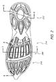
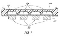
図5A〜図5B及び図7〜図8を参照して、ソール510は、ヒール領域512の前方又は前側に位置付けられた中足領域514を含む。より好ましくは、中足領域514は、左右及び前後の両方で、着用者の足の中足骨の下にある、又は実質的に中足骨の下にあるように位置付けられる。中足領域514は、好ましくは、基本層550と、裏当て層552と、基本層におけるチャンバー554と、裏当て層におけるチャンバー554’と、チャンバー554及びチャンバー554’の下にある弾性膜556と、チャンバー554及び554’に対応し、且つ弾性膜の下にあるアクチュエータ558と、ウェッビング560と、基本層の上のトッププレート562と、を含む。
With reference to FIGS. 5A-5B and FIGS. 7-8, the sole 510 includes a midfoot region 514 positioned in front of or in front of the
基本層550は、フォーム又は他の弾性材料からなることができる。いくつかの実施形態において、エラストマー粘性フォーム又はゲルは、使用されることができる。好ましい実施形態において、基本層550は、約3mmの厚さである。代替案として、基本層は、約1mm以下から約5mm以上の厚さである場合がある。基本層550の硬さは、ショアC硬度約50以下からショアC硬度約70以上の範囲であることができ、ショアC硬度55、60、及び65を含んでいる。一の実施形態において、基本層550は、ショアC硬度約58の硬さを有しているEVAからなる。図示されるように、基本層550は、上記のヒール領域の一部を形成して基本層518と一体であることができる。
The
裏当て層552は、図5A及び図7に図示されるように、基本層550の底面の一部に亘って形成されることができ、ペバックス(PEBAX)(登録商標)、ナイロン、炭素繊維、グラファイト、又はEVAなどの高剛性材料から形成されることができる。裏当て層552は、以下に記載されるように、チャンバー554を支持し、且つ補強する。いくつかの実施形態において、裏当て層は、チャンバー554の結合性を維持するようにチャンバーの間でビーム状の断面を有することができる。それらの断面は、中実である場合があり、又は例えば、略I字形状の断面、略V字形状の断面、又は略U字形状の断面を有している部分的に中空である場合がある。一の実施形態において、裏当て層552は、クリアな成形された高剛性のEVAシートから形成され、約1.5mmの厚さである場合がある。裏当て層552は、いくつかの実施形態において省略されることができ、チャンバー554は、基本層550内に形成され、基本層550によって画定される。
The
チャンバー554(図5A及び図7〜8に示される)は、略前後方向で細長くされ、中足領域514の下にある、又は実質的に下にあることができる。いくつかの実施形態において、チャンバー554はまた、つま先領域516の下にあることができる。
Chamber 554 (shown in FIGS. 5A and 7-8) is elongated in a generally anteroposterior direction and can be below or substantially below the midfoot region 514. In some embodiments, the
チャンバー554は、基本層550の底面内に窪みを形成されることができる。チャンバー554は、ソール510が中足領域514でより適合可能とされることを可能にして、互いから独立している。一の実施形態において、4つの略平行なチャンバー554は、中足領域514の実質的に下にある。いくつかの実施形態において、4つ以上又は4つ以下のチャンバーは、使用される場合がある。一の実施形態において、チャンバーのそれぞれは、各チャンバーの間で基本層の幅と略一定の幅とともに、一般的に矩形状である。チャンバーは、形状において類似である場合があり、いくつかの実施形態において、ソールの内側側部に向けているチャンバーは、外側側部にあるチャンバーより長い場合がある。チャンバーの長さは、着用者の足の寸法に依存し、チャンバーは、中足領域514、つま先領域516、又は両方のいずれかの下にある、又は実質的に下にあるであろう。例えば、いくつかの実施形態において、チャンバー554の長さは、約32mm以下から約46mm以上である場合がある。一の実施形態において、チャンバーは、より多くの垂直方向の移動並びにより良いエネルギー蓄積及びエネルギー回復を提供するために、約5mm以上又は約6mm以上の深さである。他の実施形態において、チャンバー554の深さは、履物の用途及び所望される垂直方向の移動量に依存して、約2mm以下から約12mm以上の範囲である場合がある。
The
弾性膜556は、好ましくは、チャンバー554の下にあり、且つ好ましくは、着用者の足の幅の全体又は幅の略全体に及ぶ。弾性膜は、ゴム、合成ゴム、及びデュポン社製のハイトレル(登録商標)などの高弾性の弾性材料及び高弾性の弾性フォームからなることができる。弾性膜556の弾性応答は、そのデュロメーター(durometer)及びその厚さに依存する。一の実施形態において、弾性膜556の厚さは、好ましくは、デュポン社製のハイトレル(登録商標)で約1.2mmの厚さである。他の実施形態において、弾性膜556は、約0,5mm以下と約4mm以上の間の範囲であることができ、1mm、1.5mm、2mm、3mm、及び3.5mmを含んでいる。弾性膜556は、ショアD硬度約20からショアD硬度約45までの硬さの範囲であることができ、ショアD硬度25、ショアD硬度30、ショアD硬度35、及びショアD硬度40を含んでいる。硬さ及び厚さの選択は、着用者の重量及びチャンバーへのアクチュエータの移動の所望される範囲を含んでいる、靴の特定の用途に依存する。いくつかの実施形態において、弾性膜556の厚さは、その長さ及び幅に亘って変化することができる。例えば、図3A及び図4Aに示されるように、アクチュエータ358、458の周囲に実施的に対応する弾性膜356、456の一の領域は、チャンバー354、354’、454、454’とアクチュエータ358、458との適切な位置合わせを確実にするために、弾性膜356、456の他の領域より厚い場合ある。弾性膜は、適所で弾性膜を保持するために、チャンバー554を超えて基本層で幅方向の溝(width−wise groove)を係合するその上面に幅方向の突出部を含むことができ、突出部の領域で、弾性膜の効果的な湾曲を容易にするために、その下面に対応する溝を含むこともできる。いくつかの実施形態において、弾性膜556は、他のチャンバー554に対応する弾性膜556の領域で、一のチャンバー554に弾性膜556の領域を伸張する効果を低減するために、チャンバー554の間の領域において、裏当て層552及び/基本層550に取り付けられることができる。
The
一の実施形態において、4つのアクチュエータ558は、4つのチャンバー554の下にある、又は実質的に下にある。アクチュエータ558は、弾性膜556を作用的に係合し、弾性膜556に直接的に取り付けることができる。アクチュエータ558は、例えば、接着剤によって、弾性膜556に直接的に取り付けられることができる。各アクチュエータ558は、独立チャンバー554の下に中央に配置されることができる。一の実施形態において、アクチュエータ558は、後方からフォアフット(forefoot)へ細長くされ、矩形状である。他の実施形態において、(チャンバーと同じような)アクチュエータ558は、ソールのための特定の用途に依存して、丸みを帯びる場合があり、鋭く尖らせる場合があり、又は他の形状を有することができる。いくつかの実施形態において、アクチュエータ158は、圧力が適用されると、アクチュエータが湾曲することを可能にするために、アクチュエータ558と交差して横方向に延在して、(図1に示され、図2には示されていない)湾曲溝を有することができる。
In one embodiment, the four
一の実施形態において、アクチュエータ558は、好ましくは、約7.2mmの厚さである。他の実施形態において、アクチュエータ558は、好ましくは、約6.5mmの厚さである。他の実施形態において、アクチュエータ558は、履物の用途及び所望される垂直方向の移動量に依存して、約2mm以下から約12mm以上までの厚さの範囲である場合がある場合がある。
In one embodiment, the
一の実施形態におけるアクチュエータ558は、前方へのてこ動作(levering action)を提供するために、チャンバー554と協働する。圧力がヒール領域512から中足領域514へ移動されると、アクチュエータ558は、好ましくは、チャンバー554内に垂直方向に移動する。アクチュエータ558の後方端部566は、好ましくは、アクチュエータ558の前方端部568の圧縮によって追従されて第1に圧縮される。圧力は、さらに前方へ移動され続け、アクチュエータ558の後方端部566は、好ましくは、アクチュエータ558の前方端部568より前に回復するであろう。アクチュエータ558の前方斜縁部570と連動して、このてこ動作は、好ましくは、前方への推進に対するより少ない抵抗を生み出し、蓄積されたエネルギーが前方方向で移動されることを可能にする。
ウェッビング560はまた、中足領域に設けられることができる。ウェッビング560は、ゴム又は他の耐久性材料からなることができる。図5A及び図5Bに図示されるように、ウェッビング560は、アクチュエータ558のそばに、後方に、及び前方に延在して、ともにアクチュエータを間接的に接続して、アクチュエータ558と一体であることができる。ウェッビングは、好ましくは、アクチュエータ558より薄く、アクチュエータ558は、図示された実施形態において、地面と直接的に接触し、それによって、アクチュエータ558がチャンバー554内に延在することを可能にする。一の実施形態において、ウェッビング560の厚さは一般的に、約1.5mmであり、その厚さを通じて、ウェッビングの長さ及び幅に亘って変化することができる。さらに以下に記載され、且つ図3A及び図3Bに図示されるように、ウェッビング360は、つま先領域316で示されるように、地面係合要素378と一体に形成されることができる。図5A及び図5Bを係属して参照して、ウェッビング560は、可撓性を有する弾性膜556を露出するアクチュエータ558の間に配置された開口部を有する場合がある。アクチュエータ558の間のそれらの開口部は、アクチュエータ558の独立動作を容易にするために、隣接するアクチュエータ558の間の相互作用を低減することができる。以下にさらに記載されるように、いくつかの実施形態において、ウェッビング560は、開口部594を有することができ、該開口部594を通じて、つま先パッド574が延在することができる。ウェッビング560におけるそれらの開口部は、ソールの重量が低減させることを可能にする。いくつかの実施形態において、ウェッビングは、弾性膜を完全に覆うことができる。
Webbing 560 can also be provided in the midfoot region. The
図5Bで図示されるように、フォアフットのバイオメカニクストッププレート562は、いくつかの実施形態において、チャンバー554が配置される領域に実質的に亘って延在して、中足領域514における基本層550の上に配置されることができる。トッププレート562は、炭素繊維又は熱可塑性ウレタン(TPU)などの、高剛性であるが、可撓性を有する材料からなることができる。トッププレート562は、有利には、ソール510中に圧力を分配し、フォアフットにおける中足骨を安定し、一歩一歩進んでいくために伸張及びエネルギー回復を強制し、且つ中央神経システムへの求心性フィードバック(afferent feedback)を改善する。
As illustrated in FIG. 5B, the forefoot biomechanics
いくつかの実施形態において、ソールは、1つ又は複数の剛性化要素(図示せず)を含むことができる。剛性化材料は、アクチュエータ内に配置されることができ、又はアクチュエータと弾性膜との間に配置されることができる。剛性化材料は、金属、硬質樹脂、炭素繊維、又は、他の高剛性材料からなることができる。剛性化要素は、好ましくは、チャンバーの内外への高速移動によって、てこ動作を改善するように、アクチュエータを剛性化する。剛性化要素は、透明な材料の使用とともに、フォアフットで可視されることができる。 In some embodiments, the sole can include one or more stiffening elements (not shown). The stiffening material can be placed in the actuator, or can be placed between the actuator and the elastic membrane. The stiffening material can be made of metal, hard resin, carbon fiber, or other highly rigid material. The stiffening element preferably stiffens the actuator so as to improve leverage by rapid movement in and out of the chamber. The stiffening element can be visible at the forefoot with the use of a transparent material.
一の実施形態において、中足領域に似たつま先領域は、チャンバーと、弾性膜によって分離されたアクチュエータと、を有することができる。他の実施形態において、チャンバー及びアクチュエータは、ソール510の重量を低減するために使用されない。つま先領域516は、基本層572を含むことができる。該基本層572は、着用者の足の左右及び前後のつま先領域の下にある、又は実質的に下にある。基本層572は、上記の基本層550及び518から分離されており、又は基本層550及び518と一体であることができる。図5A及び図8に示された基本層572は、好ましくは、中足領域514におけるアクチュエータ558とともに位置合わせされたパッド574を有する。パッド574は、圧力が中足領域514からつま先領域516へ移動されるにつれて、滑らかな移行を可能にする僅かな略楔形状である。パッドは、基本層がパッドの配置でより薄くなるように、基本層572の底面から下向きに延在する。各パッドは、好ましくは、互いから分離されており、且つ示された実施形態において、4つの略矩形状のパッドである。パッドは、ソールがかかとからつま先へ移動するにつれて、滑らかな処理を提供するために、パッドの前縁部に沿って傾斜されることができる。パッドの厚さは一般的に、中足領域514の下にあるアクチュエータ558の寸法及び移動の範囲に依存する。いくつかの実施形態において、パッドは、それらの最も厚いポイント、約1mm以下から約8mm以上の厚さである。一の実施形態において、パッドは、それらの最も厚いポイントで、約3.7mmの厚さである。他の実施形態において、パッド574は、地面と直接的に接触するために、ウェッビング560における開口部594を通じて延在することができる。
In one embodiment, a toe region similar to the midfoot region can have a chamber and an actuator separated by an elastic membrane. In other embodiments, the chamber and actuator are not used to reduce the weight of the sole 510.
一の実施形態において、図3A及び図3Bに示されるように、つま先領域316は、パッド374のそれぞれの下にあることができる地面係合要素378をさらに含むことができる。地面係合要素378は、中足領域でウェッビング360と一体に形成されることができ、且つ同様に、ゴム又は他の耐久性材料からなることができる。一の実施形態において、地面係合要素378の厚さは、約1.5mmである。地面係合要素378及びウェッビング360が一体に形成される場合に、一体に形成された構成要素は、各地面係合要素378の両側部に開口部を含むことができる。いくつかの実施形態において、図4A及び図5Aに図示されたそれらのような、ウェッビング460、560は、1つ又は複数の開口部494、594を有することができる。パッド474、574は、該開口部494、594を通じて延在し、ソールの重量を低減することができる。
In one embodiment, as shown in FIGS. 3A and 3B, the
一の実施形態において、図5A及び図5Bに図示されるように、ソール510は、下部屈曲溝582を有している屈曲領域580を含み、下部屈曲溝582は、中足領域514とつま先領域516との間に配置され、左右に延在している。下部屈曲溝582は、人間の足の中足骨頭とつま先との間の領域の実質的に下にあるように湾曲されることができる。ウェッビング560は、いくつかの実施形態において、下部屈曲溝582の一部に延在することができる。他の実施形態において、図3A及び図3Bに図示されるように、ウェッビング360は、下部屈曲溝382の略全長に沿って下部屈曲溝382内に延在することができる。屈曲領域580はまた、図5B及び図8に示されるように、基本層の上面に上部屈曲溝584を含むことができる。上部屈曲溝584は、下部湾曲溝582の実質的に上にあることができる。一の実施形態における屈曲領域580は、足からの最終的な推進の自然な移動を可能にし、且つ靴における湾曲からのエネルギー消費を制限するように、湾曲を容易にする。一の実施形態において、図9に示されるように、ソールは、着用者のつま先の下に押圧している屈曲溝986を含むことができる。
In one embodiment, as illustrated in FIGS. 5A and 5B, the sole 510 includes a bent region 580 having a lower
一の実施形態において、図9−11を参照して、可変密度フォームは、基本層988のために使用されることができる。基本層988は、着用者の足の全体の下にあるが、必要に応じ、所望される支持を提供するために異なる密度を含む。例えば、より硬い又はより高密度のフォームは、ヒール領域とつま先領域との間に延在する足の内側側部などの、1つ又は複数の領域990で使用されることができる。図10で示されるように、より硬く、より高密度であり、又は異なるフォームは、中足領域の1つ又は複数のチャンバーを通じて延在することができる。他の実施形態において、より硬い又はより高密度のフォームは、歩行サイクルの推進部分中に、後期の回内運動又は回外運動(late stage pronation or supination)に抵抗するように、様々な外側領域又は内側領域で使用されることができる。より硬いフォームは、いくつかの実施形態において、ショアC硬度約65以下からショアC硬度約75以上までの硬さの範囲である場合がある。さらなる他の実施形態において、異なる構成要素は、異なる硬さ又は密度でなされることができる。例えば、中足領域及び/又はヒール領域の弾性膜は、所望される性質を提供するために異なる領域で異なる密度でなされることができる。
In one embodiment, referring to FIGS. 9-11, a variable density foam can be used for the
上述された様々な実施形態は、本発明を実施するための複数の方法を提供し、様々な組み合わせで利用されることができる。例えば、一の実施形態において、ソールは、図5A、図5B、及び図6Cで示されたヒール領域と、図7に示された中足領域とを有して構成されることができる。他の実施形態において、ソールは、図5A、図5B、及び図6Cに示されたヒール領域と、図7に示された中足領域と、図9−11に示される基本層と、を有して構成されることができる。他の実施形態において、ソールは、図4A、図4B、及び図6Bのヒール領域と、図7の中足領域とを有して構成されることができる。他の実施形態において、ソールは、図4A、図4B、及び図6Bのヒール領域と、図7の中足領域と、図9−11の基本層と、を有して構成されることができる。他の変形は、同様に予想される。 The various embodiments described above provide multiple ways to implement the invention and can be utilized in various combinations. For example, in one embodiment, the sole can be configured with the heel region shown in FIGS. 5A, 5B, and 6C and the midfoot region shown in FIG. In other embodiments, the sole has the heel region shown in FIGS. 5A, 5B, and 6C, the midfoot region shown in FIG. 7, and the base layer shown in FIGS. 9-11. Can be configured. In other embodiments, the sole can be configured with the heel region of FIGS. 4A, 4B, and 6B and the midfoot region of FIG. In other embodiments, the sole can be configured with the heel region of FIGS. 4A, 4B, and 6B, the midfoot region of FIG. 7, and the base layer of FIGS. 9-11. . Other variations are anticipated as well.
もちろん、必ずしも、記載された全ての目的又は利点が本明細書に記載されたいずれかの特定の実施形態に従って、達成されることができることがないことは、理解されるべきである。また、本発明が特定の実施形態及び実施例の関連で開示されるけれども、本発明が特に開示された実施形態を超えて、他の代替的な実施形態、及び/又は使用、並びにそれらの明らかな改良及び相当物まで延在することは、当業者によって理解されるであろう。それ故に、本発明は、好ましい実施形態の特定の開示によって制限されるように意図されない。 Of course, it is to be understood that not necessarily all objects or advantages described may be achieved in accordance with any particular embodiment described herein. Also, although the invention is disclosed in the context of particular embodiments and examples, the invention is beyond the specifically disclosed embodiments, and other alternative embodiments and / or uses, and obvious It will be understood by those skilled in the art that the present invention extends to other improvements and equivalents. Accordingly, the present invention is not intended to be limited by the specific disclosures of preferred embodiments.
110 ソール
112 ヒール領域
114 中足領域
116 つま先領域
312 ヒール領域
316 つま先領域
318 基本層
320 中央アクチュエータ
322 内側アクチュエータ
324 外側アクチュエータ
326 弾性膜
328 ヒール層
330 中央チャンバー
332 周辺チャンバー
334 周辺チャンバー
336 地面係合要素
338 トッププレート
340 中央開口部
342 内側凹所
344 外側凹所
346 上面
348 底面
360 ウェッビング
378 地面係合要素
382 下部屈曲溝
392 領域
426 弾性膜
428 ヒール層
474 パッド
494 開口部
510 ソール
512 ヒール領域
514 中足領域
516 つま先領域
518 基本層
526 弾性膜
530 中央チャンバー
532 周辺チャンバー
534 周辺チャンバー
550 基本層
552 裏当て層
554 チャンバー
554’ チャンバー
556 弾性膜
558 アクチュエータ
560 ウェッビング
562 トッププレート
566 後方端部
568 前方端部
570 前方斜縁部
572 基本層
574 パッド
582 下部屈曲溝
584 上部屈曲溝
594 開口部
986 屈曲溝
988 基本層
990 領域
110 sole 112 heel region 114
Claims (13)
底面に面する複数の独立したチャンバーを画定する基本層であって、各チャンバーが略前後方向で細長く形成される、基本層と、
前記複数のチャンバーを覆う少なくとも1つの弾性膜と、
前記足の中足領域の下にあるように寸法決めされ、且つ位置付けられる複数のアクチュエータであって、前記複数のアクチュエータが略前後方向で細長く形成されており、前記複数のアクチュエータが前記少なくとも1つの弾性膜に対して圧縮される場合に、前記複数のチャンバーが前記少なくとも1つの弾性膜の部分を少なくとも部分的に受容するように、前記複数のアクチュエータ及び前記複数のチャンバーが寸法決めされ、且つ位置付けられる、複数のアクチュエータと、
を備えることを特徴とするソール構造。 A sole structure for buffering a region of a foot, supporting a region of the foot, and providing energy recovery to the region of the foot,
A basic layer defining a plurality of independent chambers facing the bottom surface, wherein each chamber is elongated in a substantially front-rear direction;
At least one elastic membrane covering the plurality of chambers;
A plurality of actuators dimensioned and positioned to be below the midfoot region of the foot, wherein the plurality of actuators are elongated in a generally longitudinal direction, wherein the plurality of actuators are the at least one The plurality of actuators and the plurality of chambers are sized and positioned such that, when compressed against an elastic membrane, the plurality of chambers at least partially receive a portion of the at least one elastic membrane. A plurality of actuators,
A sole structure comprising:
圧力が使用者の足の一の領域から他の領域へ伝達されるにつれて、前記第1の端部は、前記第2の端部より前に対応するチャンバー内に入り、前記第1の端部は、前記第2の端部より前に前記対応するチャンバーから戻ることを特徴とする請求項1〜4のいずれか一項に記載のソール構造。 The at least one actuator has a first end and a second end;
As pressure is transmitted from one region of the user's foot to another region, the first end enters the corresponding chamber prior to the second end, and the first end The sole structure according to claim 1, wherein the sole structure returns from the corresponding chamber before the second end.
前記少なくとも1つの上部溝及び前記少なくとも1つの下部溝は、略外内方向に延在していることを特徴とする請求項1〜6のいずれか一項に記載のソール構造。 The base layer has a bent region having at least one upper groove and at least one lower groove;
The sole structure according to any one of claims 1 to 6, wherein the at least one upper groove and the at least one lower groove extend in a substantially outer-inward direction.
前記ソール構造は、
前記基本層の前記少なくとも1つの中央凹所内に位置付けられる少なくとも1つの中央アクチュエータと、
前記中央アクチュエータの第1の側に中央アクチュエータによって係合された弾性膜部分と、
前記弾性膜部分の第2の側に中央チャンバーを有しているチャンバー層であって、該チャンバー層の前記中央チャンバーが前記少なくとも1つの中央アクチュエータと垂直方向に位置合わせされる、チャンバー層と、
を備えることを特徴とする請求項1又は2に記載のソール構造。 The base layer defines at least one central recess;
The sole structure is
At least one central actuator positioned in the at least one central recess of the base layer;
An elastic membrane portion engaged by a central actuator on a first side of the central actuator;
A chamber layer having a central chamber on a second side of the elastic membrane portion, wherein the central chamber of the chamber layer is vertically aligned with the at least one central actuator;
The sole structure according to claim 1, further comprising:
前記ソール構造は、前記基本層における前記周辺凹所内に位置付けられた複数の周辺アクチュエータをさらに備えており、
前記弾性膜部分は、前記周辺アクチュエータの第1の側で前記周辺アクチュエータによってさらに係合され、
前記チャンバー層は、前記弾性膜部分の前記第2の側で複数の周辺チャンバーを有し、
前記チャンバー層の前記周辺チャンバーは、前記周辺アクチュエータと垂直方向に位置合わせされることを特徴とする請求項9に記載のソール構造。 The base layer further defines a plurality of peripheral recesses,
The sole structure further comprises a plurality of peripheral actuators positioned in the peripheral recesses in the base layer;
The elastic membrane portion is further engaged by the peripheral actuator on a first side of the peripheral actuator;
The chamber layer may include a plurality of peripheral chambers at the second side of the elastic-membrane portion,
The sole structure according to claim 9, wherein the peripheral chamber of the chamber layer is aligned in a direction perpendicular to the peripheral actuator.
Applications Claiming Priority (3)
| Application Number | Priority Date | Filing Date | Title |
|---|---|---|---|
| US85708906P | 2006-11-06 | 2006-11-06 | |
| US60/857,089 | 2006-11-06 | ||
| PCT/US2007/083818 WO2008058147A2 (en) | 2006-11-06 | 2007-11-06 | Sole construction for energy storage and rebound |
Publications (3)
| Publication Number | Publication Date |
|---|---|
| JP2010508913A JP2010508913A (en) | 2010-03-25 |
| JP2010508913A5 JP2010508913A5 (en) | 2011-01-06 |
| JP5355409B2 true JP5355409B2 (en) | 2013-11-27 |
Family
ID=39327001
Family Applications (1)
| Application Number | Title | Priority Date | Filing Date |
|---|---|---|---|
| JP2009535506A Active JP5355409B2 (en) | 2006-11-06 | 2007-11-06 | Sole structure for energy storage and recovery |
Country Status (6)
| Country | Link |
|---|---|
| US (2) | US9578922B2 (en) |
| EP (2) | EP2807939A1 (en) |
| JP (1) | JP5355409B2 (en) |
| KR (1) | KR20090109530A (en) |
| CN (1) | CN101573058A (en) |
| WO (1) | WO2008058147A2 (en) |
Cited By (1)
| Publication number | Priority date | Publication date | Assignee | Title |
|---|---|---|---|---|
| US9578922B2 (en) | 2006-11-06 | 2017-02-28 | Newton Running Company, Inc. | Sole construction for energy storage and rebound |
Families Citing this family (50)
| Publication number | Priority date | Publication date | Assignee | Title |
|---|---|---|---|---|
| US20020157280A1 (en) * | 2000-12-01 | 2002-10-31 | Russell Brian A. | Sole construction for energy storage and rebound |
| US8099880B2 (en) * | 2009-01-05 | 2012-01-24 | Under Armour, Inc. | Athletic shoe with cushion structures |
| CA2764304A1 (en) * | 2009-06-02 | 2010-12-09 | Forme Limited | Wellness shoe and method |
| US10952493B1 (en) * | 2011-03-28 | 2021-03-23 | Jeffrey Brian Downard | Flexible forefoot protection for insoles and shoes |
| US8732981B2 (en) | 2011-04-20 | 2014-05-27 | John E. Cobb | Eccentric toe-off cam lever |
| US9149087B2 (en) | 2011-08-05 | 2015-10-06 | Newton Running Company, Inc. | Shoe soles for shock absorption and energy return |
| KR101447260B1 (en) * | 2012-05-21 | 2014-10-08 | 정주민 | Shoe soles consisting of cushion materials a production method thereof |
| US9282784B2 (en) * | 2012-09-06 | 2016-03-15 | Nike, Inc. | Sole structures and articles of footwear having a lightweight midsole with segmented protective elements |
| EP2914143A4 (en) * | 2012-11-05 | 2016-07-20 | Feet2 Oy | Midsole structure for a sports shoe and sports shoe |
| US9930928B2 (en) | 2013-02-13 | 2018-04-03 | Adidas Ag | Sole for a shoe |
| DE102013202306B4 (en) | 2013-02-13 | 2014-12-18 | Adidas Ag | Sole for a shoe |
| KR101414554B1 (en) | 2013-02-28 | 2014-07-01 | 권경철 | Sole for functional walking shoes |
| KR101414555B1 (en) | 2013-02-28 | 2014-07-01 | 권경철 | Sole for functional walking shoes including shank |
| US20140259746A1 (en) * | 2013-03-14 | 2014-09-18 | Newton Running | Sole Construction for Elastic Energy Return |
| US9386820B2 (en) | 2013-03-15 | 2016-07-12 | Rikco International Llc | Pressure relief system for footwear |
| US20140310981A1 (en) * | 2013-04-23 | 2014-10-23 | Newton Running Company, Inc. | Sole construction for biomechanical stability and afferent feedback |
| US9629414B2 (en) * | 2013-07-11 | 2017-04-25 | Nike, Inc. | Sole structure for an article of footwear |
| US9456656B2 (en) * | 2013-09-18 | 2016-10-04 | Nike, Inc. | Midsole component and outer sole members with auxetic structure |
| USD748902S1 (en) * | 2013-12-31 | 2016-02-09 | Brooks Sports, Inc. | Shoe |
| US9955749B2 (en) * | 2014-01-14 | 2018-05-01 | Nike, Inc. | Footwear having sensory feedback outsole |
| US10602799B2 (en) * | 2014-04-03 | 2020-03-31 | Nfinity Ip, Llc | Athletic shoe with energy return system |
| JP6679363B2 (en) | 2015-03-23 | 2020-04-15 | アディダス アーゲー | Soles and shoes |
| EP3112492A1 (en) | 2015-06-29 | 2017-01-04 | Vallourec Oil And Gas France | Corrosion resistant steel, method for producing said steel and its use thereof |
| USD804793S1 (en) * | 2015-08-28 | 2017-12-12 | Chinook Asia Llc | Boot outsole |
| USD801658S1 (en) * | 2015-09-17 | 2017-11-07 | Wolverine Outdoors, Inc. | Footwear sole |
| USD793047S1 (en) * | 2015-10-19 | 2017-08-01 | Nike, Inc. | Shoe outsole |
| USD791454S1 (en) * | 2015-11-17 | 2017-07-11 | Nike, Inc. | Shoe outsole |
| USD796799S1 (en) * | 2015-11-17 | 2017-09-12 | Nike, Inc. | Shoe midsole |
| USD814755S1 (en) * | 2016-03-23 | 2018-04-10 | Under Armour, Inc. | Shoe sole |
| USD802897S1 (en) * | 2016-03-23 | 2017-11-21 | Under Armour, Inc. | Shoe sole |
| USD788428S1 (en) * | 2016-06-03 | 2017-06-06 | Skechers U.S.A., Inc. Ii | Shoe outsole bottom |
| USD812878S1 (en) * | 2016-11-16 | 2018-03-20 | Nike, Inc. | Shoe outsole |
| USD811717S1 (en) * | 2016-11-30 | 2018-03-06 | Nike, Inc. | Shoe |
| USD849381S1 (en) * | 2017-02-02 | 2019-05-28 | Under Armour, Inc. | Sole structure |
| USD853096S1 (en) * | 2017-03-07 | 2019-07-09 | Under Armour, Inc. | Sole structure |
| USD844958S1 (en) * | 2017-03-09 | 2019-04-09 | Under Armour, Inc. | Sole structure |
| CN106937771A (en) * | 2017-03-10 | 2017-07-11 | 福建起步儿童用品有限公司 | A kind of ventilated breathing shoes bottom and its footwear |
| US11284671B2 (en) | 2017-03-24 | 2022-03-29 | Nike, Inc. | Article of footwear incorporating particulate matter |
| USD840650S1 (en) * | 2017-03-30 | 2019-02-19 | Under Armour, Inc. | Sole structure |
| USD831316S1 (en) * | 2017-05-26 | 2018-10-23 | Under Armour, Inc. | Shoe sole |
| USD858061S1 (en) * | 2017-07-06 | 2019-09-03 | Mylissa C. Couch | Shoes |
| IT201700089835A1 (en) * | 2017-08-03 | 2019-02-03 | Base Prot S R L | Active system with variable geometry with damping, energy dissipation and stabilization functions, which can be integrated into the soles of footwear |
| KR101898076B1 (en) * | 2017-09-19 | 2018-10-04 | 안태훈 | Outsole of shoes |
| TWI721226B (en) * | 2017-11-03 | 2021-03-11 | 寶成工業股份有限公司 | Shoe and shoe composite structure manufacturing method |
| US10986896B2 (en) * | 2018-01-22 | 2021-04-27 | Adidas Ag | Article of footwear with ribbed outsole and notched midsole |
| US11583029B2 (en) | 2018-01-22 | 2023-02-21 | Adidas Ag | Article of footwear with ribbed outsole and notched midsole |
| USD896492S1 (en) * | 2018-11-30 | 2020-09-22 | Under Armour, Inc. | Sole structure |
| US11122857B2 (en) * | 2019-06-12 | 2021-09-21 | Wolverine Outdoors, Inc. | Footwear cushioning sole assembly |
| DE102019131377B3 (en) * | 2019-11-20 | 2021-03-11 | Betterguards Technology Gmbh | Device for stabilizing movements of two parts of a human body area that can move relative to one another and / or of a sports device with a pivotable force transmission element, as well as shoe and shoe sole comprising the device |
| USD936348S1 (en) * | 2020-12-22 | 2021-11-23 | Nike, Inc. | Shoe |
Family Cites Families (117)
| Publication number | Priority date | Publication date | Assignee | Title |
|---|---|---|---|---|
| US904891A (en) | 1908-08-27 | 1908-11-24 | Henry Otterstedt | Ventilating-sole. |
| US1382180A (en) * | 1919-12-22 | 1921-06-21 | Elias J Emery | Sole-tap for boots and shoes |
| US1778089A (en) * | 1929-07-09 | 1930-10-14 | Pomerantz Joseph | Rubber-heel-attaching plate for shoes |
| US1993208A (en) * | 1930-06-28 | 1935-03-05 | Cohn Abraham | Shoe |
| US1993028A (en) | 1932-03-14 | 1935-03-05 | Hercules Powder Co Ltd | Composition of matter and method of producing |
| US2058975A (en) * | 1936-07-01 | 1936-10-27 | Ernest A Gray | Shoemaking |
| US2549343A (en) * | 1949-02-17 | 1951-04-17 | Stoiner Stephen | Cushion sole |
| US2811791A (en) | 1956-12-24 | 1957-11-05 | Ivan E Cox | Weight distributing shoe shank |
| US3086532A (en) * | 1961-09-13 | 1963-04-23 | Mistarz Marion | Contoured sole for footwear |
| US3100354A (en) * | 1962-12-13 | 1963-08-13 | Lombard Herman | Resilient shoe sole |
| DE1485580A1 (en) | 1964-07-01 | 1969-02-20 | Alfred Bente | Sports shoe, in particular jumping shoe |
| US3402485A (en) * | 1966-05-13 | 1968-09-24 | United Shoe Machinery Corp | Animal track footwear soles |
| US3834046A (en) * | 1973-04-09 | 1974-09-10 | D Fowler | Shoe sole structure |
| US4372058A (en) * | 1977-11-21 | 1983-02-08 | Stubblefield Jerry D | Shoe sole construction |
| DE2753205C3 (en) * | 1977-11-29 | 1985-12-12 | Michael W. Dipl.-Kfm. 5100 Aachen Schmohl | Full outsole for sports shoes |
| US4187620A (en) * | 1978-06-15 | 1980-02-12 | Selner Allen J | Biomechanical shoe |
| ZA784637B (en) * | 1978-08-15 | 1979-09-26 | J Halberstadt | Footware |
| USRE33066E (en) * | 1980-05-06 | 1989-09-26 | Avia Group International, Inc. | Shoe sole construction |
| US4335530A (en) * | 1980-05-06 | 1982-06-22 | Stubblefield Jerry D | Shoe sole construction |
| GB2272759B (en) * | 1983-12-23 | 1994-11-23 | Gec Ferranti Defence Syst | Detector apparatus for detecting coherent point-source radiation |
| JPS60150701A (en) * | 1984-01-17 | 1985-08-08 | 株式会社アシックス | Middle sole for sports shoes |
| DE3507295A1 (en) | 1985-03-01 | 1986-09-04 | LICO - Sportschuhfabriken Link & Co GmbH, 8620 Lichtenfels | Sole |
| US4785557A (en) | 1986-10-24 | 1988-11-22 | Avia Group International, Inc. | Shoe sole construction |
| US4798009A (en) * | 1987-05-11 | 1989-01-17 | Colonel Richard C | Spring apparatus for shoe soles and the like |
| US4843735A (en) * | 1987-06-12 | 1989-07-04 | Kabushiki Kaisha Cubic Engineering | Shock absorbing type footwear |
| US4897937A (en) * | 1987-09-23 | 1990-02-06 | Colgate-Palmolive Company | Non-slip insole base |
| US4922631A (en) * | 1988-02-08 | 1990-05-08 | Adidas Sportschuhfabriken Adi Dassier Stiftung & Co. Kg | Shoe bottom for sports shoes |
| CA1338369C (en) * | 1988-02-24 | 1996-06-11 | Jean-Pierre Vermeulen | Shock absorbing system for footwear application |
| US5185943A (en) * | 1988-07-29 | 1993-02-16 | Avia Group International, Inc. | Athletic shoe having an insert member in the outsole |
| US5083910A (en) * | 1988-08-11 | 1992-01-28 | Abshire Danny P | Insole assembly base component molding pad |
| US4888887A (en) | 1988-11-09 | 1989-12-26 | Solow Terry S | Suction-ventilated shoe system |
| US4956927A (en) * | 1988-12-20 | 1990-09-18 | Colgate-Palmolive Company | Monolithic outsole |
| GB8909021D0 (en) | 1989-04-20 | 1989-06-07 | Trisport Ltd | Footwear |
| USD321975S (en) | 1989-04-26 | 1991-12-03 | Salomon S.A. | Sole section of a sport shoe |
| IT1226514B (en) * | 1989-05-24 | 1991-01-24 | Fila Sport | SPORTS FOOTWEAR INCORPORATING, IN THE HEEL, AN ELASTIC INSERT. |
| US5005299A (en) * | 1990-02-12 | 1991-04-09 | Whatley Ian H | Shock absorbing outsole for footwear |
| DE4015138A1 (en) | 1990-05-11 | 1991-11-14 | Reinhold Vogl | Footwear with healthy action - has textile covered hard elastic multi-section shell forming intermediate sole |
| US5224277A (en) * | 1990-05-22 | 1993-07-06 | Kim Sang Do | Footwear sole providing ventilation, shock absorption and fashion |
| US5595003A (en) * | 1990-08-21 | 1997-01-21 | Snow; A. Ray | Athletic shoe with a force responsive sole |
| WO1993003639A1 (en) | 1991-08-20 | 1993-03-04 | Albert Ray Snow | Athletic shoe with a force responsive sole |
| WO1992003069A1 (en) | 1990-08-21 | 1992-03-05 | Albert Ray Snow | Athletic shoe with a force responsive sole |
| USD326956S (en) * | 1990-10-10 | 1992-06-16 | Damianoe Joseph R | Billiard shoe sole |
| USD331832S (en) | 1991-01-30 | 1992-12-22 | H. H. Brown Shoe Company, Inc. | Shoe sole |
| US5195257A (en) * | 1991-02-05 | 1993-03-23 | Holcomb Robert R | Athletic shoe sole |
| JP2807939B2 (en) | 1991-07-18 | 1998-10-08 | 株式会社 東京商会 | Powder take-out device |
| US5353523A (en) * | 1991-08-02 | 1994-10-11 | Nike, Inc. | Shoe with an improved midsole |
| US5319866A (en) * | 1991-08-21 | 1994-06-14 | Reebok International Ltd. | Composite arch member |
| JP3471011B2 (en) * | 1991-09-26 | 2003-11-25 | スカイデックス・テクノロジーズ・インコーポレーテッド | Shoe sole components |
| US5311680A (en) * | 1991-11-07 | 1994-05-17 | Comparetto John E | Dynamic orthotic |
| US5598645A (en) * | 1992-01-02 | 1997-02-04 | Adidas Ab | Shoe sole, in particular for sports shoes, with inflatable tube elements |
| US5440826A (en) * | 1992-04-08 | 1995-08-15 | Whatley; Ian H. | Shock absorbing outsole for footwear |
| US6065229A (en) * | 1992-05-26 | 2000-05-23 | Wahrheit; Gerhard Maximilian | Multiple-part foot-support sole |
| IT1265768B1 (en) | 1992-06-05 | 1996-12-02 | Menghi Shoes Srl | SELF-ASSASSING INSOLE INSOLE FOR SLIPPERS OR CLOGS |
| USD343272S (en) * | 1992-10-19 | 1994-01-18 | Guess?, Inc. | Shoe sole |
| US5384973A (en) | 1992-12-11 | 1995-01-31 | Nike, Inc. | Sole with articulated forefoot |
| US5367791A (en) | 1993-02-04 | 1994-11-29 | Asahi, Inc. | Shoe sole |
| US5615497A (en) * | 1993-08-17 | 1997-04-01 | Meschan; David F. | Athletic shoe with improved sole |
| US5560126A (en) * | 1993-08-17 | 1996-10-01 | Akeva, L.L.C. | Athletic shoe with improved sole |
| US5918384A (en) | 1993-08-17 | 1999-07-06 | Akeva L.L.C. | Athletic shoe with improved sole |
| USD347105S (en) * | 1993-09-01 | 1994-05-24 | Nike, Inc. | Shoe sole |
| US5465507A (en) | 1994-04-13 | 1995-11-14 | Osage Footwear, Inc. | Integral sole with footprint embossing |
| US5461800A (en) * | 1994-07-25 | 1995-10-31 | Adidas Ag | Midsole for shoe |
| US6266897B1 (en) * | 1994-10-21 | 2001-07-31 | Adidas International B.V. | Ground-contacting systems having 3D deformation elements for use in footwear |
| US5625963A (en) * | 1994-11-01 | 1997-05-06 | American Sporting Goods Corp. | Sole construction for footwear |
| US5647145A (en) | 1995-06-05 | 1997-07-15 | Russell; Brian | Sculptured athletic footwear sole construction |
| US5718063A (en) * | 1995-07-17 | 1998-02-17 | Asics Corporation | Midsole cushioning system |
| US5806210A (en) | 1995-10-12 | 1998-09-15 | Akeva L.L.C. | Athletic shoe with improved heel structure |
| IT1277026B1 (en) | 1995-12-04 | 1997-11-04 | Global Sports Tech Inc | SPORTS SHOES WITH SOLE HAVING AT LEAST ONE PARTLY INTERESTING LAYER, THE SOLE ITSELF IN COMPOSITE MATERIAL |
| IT1283052B1 (en) * | 1996-05-22 | 1998-04-07 | Brue S P A | SOLE-INSOLE SET, BREATHABLE IN A SINGLE DIRECTION, FOR FORCED AREA SHOES |
| US6219939B1 (en) * | 1997-04-18 | 2001-04-24 | Mizuno Corporation | Athletic shoe midsole design and construction |
| US6314664B1 (en) | 1997-04-18 | 2001-11-13 | Mizuno Corporation | Athletic shoe midsole design and construction |
| US5815949A (en) | 1997-06-10 | 1998-10-06 | Sessa; Raymond V. | Footwear insert providing air circulation |
| US6327795B1 (en) * | 1997-07-30 | 2001-12-11 | Britek Footwear Development, Llc | Sole construction for energy storage and rebound |
| RU2238016C2 (en) | 1997-07-30 | 2004-10-20 | Бритек Футвэр Девелопмент Ллс | Sole structure for accumulating and releasing of energy |
| US5937544A (en) * | 1997-07-30 | 1999-08-17 | Britek Footwear Development, Llc | Athletic footwear sole construction enabling enhanced energy storage, retrieval and guidance |
| US6330757B1 (en) * | 1998-08-18 | 2001-12-18 | Britek Footwear Development, Llc | Footwear with energy storing sole construction |
| WO1999035928A1 (en) | 1998-01-20 | 1999-07-22 | Snow A Ray | Shoe with force responsive sole |
| US20020121031A1 (en) * | 1998-01-30 | 2002-09-05 | Steven Smith | 2a improvements |
| DE29801638U1 (en) * | 1998-01-31 | 1998-05-20 | Danza S R L | Shoes, in particular sports or dance shoes |
| US6038790A (en) * | 1998-02-26 | 2000-03-21 | Nine West Group, Inc. | Flexible sole with cushioned ball and/or heel regions |
| US6519876B1 (en) * | 1998-05-06 | 2003-02-18 | Kenton Geer Design Associates, Inc. | Footwear structure and method of forming the same |
| US6061929A (en) * | 1998-09-04 | 2000-05-16 | Deckers Outdoor Corporation | Footwear sole with integrally molded shank |
| JP3258628B2 (en) * | 1998-09-08 | 2002-02-18 | 株式会社アシックス | Athletic shoes |
| JP3238132B2 (en) * | 1998-10-02 | 2001-12-10 | 美津濃株式会社 | Midsole structure for sports shoes |
| US6438870B2 (en) * | 1998-11-05 | 2002-08-27 | Asics Corporation | Shoe sole with shock absorber structure |
| US6412196B1 (en) * | 1999-03-26 | 2002-07-02 | Alexander L. Gross | Contoured platform and footwear made therefrom |
| US6354020B1 (en) * | 1999-09-16 | 2002-03-12 | Reebok International Ltd. | Support and cushioning system for an article of footwear |
| JP3542756B2 (en) * | 2000-02-25 | 2004-07-14 | 美津濃株式会社 | Midsole structure for sports shoes |
| US20020157280A1 (en) | 2000-12-01 | 2002-10-31 | Russell Brian A. | Sole construction for energy storage and rebound |
| US6457261B1 (en) | 2001-01-22 | 2002-10-01 | Ll International Shoe Company, Inc. | Shock absorbing midsole for an athletic shoe |
| FR2823955B1 (en) | 2001-04-27 | 2004-01-16 | Jean Jacques Durand | SOLE WITH AN EXPANDABLE STRUCTURE, ARTICLE OF FOOTWEAR PROVIDED WITH SUCH A SOLE AND ITS ASSEMBLY METHOD |
| JP4906153B2 (en) | 2001-06-28 | 2012-03-28 | 美津濃株式会社 | Midsole structure for sports shoes |
| US6694642B2 (en) * | 2001-09-28 | 2004-02-24 | American Sporting Goods Corporation | Shoe incorporating improved shock absorption and stabilizing elements |
| US6598320B2 (en) * | 2001-09-28 | 2003-07-29 | American Sporting Goods Corporation | Shoe incorporating improved shock absorption and stabilizing elements |
| US6964120B2 (en) | 2001-11-02 | 2005-11-15 | Nike, Inc. | Footwear midsole with compressible element in lateral heel area |
| US6851204B2 (en) | 2001-11-15 | 2005-02-08 | Nike, Inc. | Footwear sole with a stiffness adjustment mechanism |
| US6898870B1 (en) * | 2002-03-20 | 2005-05-31 | Nike, Inc. | Footwear sole having support elements with compressible apertures |
| AU2003203502B2 (en) * | 2002-04-10 | 2005-05-19 | Wolverine World Wide, Inc. | Footwear Sole |
| US6745499B2 (en) * | 2002-05-24 | 2004-06-08 | Reebok International Ltd. | Shoe sole having a resilient insert |
| US20040123493A1 (en) * | 2002-06-12 | 2004-07-01 | Russell Brian A. | Sole construction for footwear having metal components |
| DE10234913B4 (en) * | 2002-07-31 | 2005-11-10 | Adidas International Marketing B.V. | sole |
| DE10244435B4 (en) | 2002-09-24 | 2006-02-16 | Adidas International Marketing B.V. | Sliding element and shoe sole |
| US7080467B2 (en) * | 2003-06-27 | 2006-07-25 | Reebok International Ltd. | Cushioning sole for an article of footwear |
| US7331124B2 (en) * | 2003-08-22 | 2008-02-19 | Akeva L.L.C. | Plate support for athletic shoe |
| US7020988B1 (en) * | 2003-08-29 | 2006-04-04 | Pierre Andre Senizergues | Footwear with enhanced impact protection |
| US7096605B1 (en) * | 2003-10-08 | 2006-08-29 | Nike, Inc. | Article of footwear having an embedded plate structure |
| US7386945B2 (en) * | 2003-10-30 | 2008-06-17 | Reebok International Ltd. | Sole for increased circulation |
| US7100310B2 (en) * | 2003-12-23 | 2006-09-05 | Nike, Inc. | Article of footwear having a fluid-filled bladder with a reinforcing structure |
| US7020990B2 (en) * | 2004-01-13 | 2006-04-04 | M. Steven Khoury | Orthopedic device for distributing pressure |
| US20050193589A1 (en) | 2004-01-23 | 2005-09-08 | Kevin Bann | Sole for a shoe, boot or sandal |
| US7200955B2 (en) | 2004-06-04 | 2007-04-10 | Nike, Inc. | Article of footwear incorporating a sole structure with compressible inserts |
| US7334349B2 (en) * | 2004-08-24 | 2008-02-26 | Nike, Inc. | Midsole element for an article of footwear |
| US7441346B2 (en) * | 2004-12-28 | 2008-10-28 | Saucony, Inc. | Athletic shoe with independent supports |
| US7726042B2 (en) * | 2005-03-23 | 2010-06-01 | Meschan David F | Athletic shoe with removable resilient element |
| US7380353B2 (en) * | 2005-07-22 | 2008-06-03 | Ariat International, Inc. | Footwear sole with forefoot stabilizer, ribbed shank, and layered heel cushioning |
| US7555845B2 (en) | 2006-08-10 | 2009-07-07 | Cooper Brands, Inc. | Automatic locking tape measure |
| KR20090109530A (en) | 2006-11-06 | 2009-10-20 | 뉴톤 러닝 컴퍼니, 인크. | Sole construction for energy storage and rebound |
-
2007
- 2007-11-06 KR KR1020097011587A patent/KR20090109530A/en not_active Application Discontinuation
- 2007-11-06 CN CNA2007800492343A patent/CN101573058A/en active Pending
- 2007-11-06 WO PCT/US2007/083818 patent/WO2008058147A2/en active Application Filing
- 2007-11-06 EP EP14176724.4A patent/EP2807939A1/en not_active Withdrawn
- 2007-11-06 US US12/513,833 patent/US9578922B2/en active Active
- 2007-11-06 EP EP07863992A patent/EP2091372A2/en not_active Withdrawn
- 2007-11-06 JP JP2009535506A patent/JP5355409B2/en active Active
-
2012
- 2012-11-26 US US13/685,197 patent/US10045589B2/en active Active
Cited By (2)
| Publication number | Priority date | Publication date | Assignee | Title |
|---|---|---|---|---|
| US9578922B2 (en) | 2006-11-06 | 2017-02-28 | Newton Running Company, Inc. | Sole construction for energy storage and rebound |
| US10045589B2 (en) | 2006-11-06 | 2018-08-14 | Newton Running Company, Inc. | Sole construction for energy storage and rebound |
Also Published As
| Publication number | Publication date |
|---|---|
| EP2091372A2 (en) | 2009-08-26 |
| EP2807939A1 (en) | 2014-12-03 |
| US10045589B2 (en) | 2018-08-14 |
| WO2008058147A3 (en) | 2008-06-26 |
| JP2010508913A (en) | 2010-03-25 |
| US20130081304A1 (en) | 2013-04-04 |
| US20100031530A1 (en) | 2010-02-11 |
| WO2008058147A2 (en) | 2008-05-15 |
| US9578922B2 (en) | 2017-02-28 |
| CN101573058A (en) | 2009-11-04 |
| KR20090109530A (en) | 2009-10-20 |
Similar Documents
| Publication | Publication Date | Title |
|---|---|---|
| JP5355409B2 (en) | Sole structure for energy storage and recovery | |
| US8732983B2 (en) | Shoes, devices for shoes, and methods of using shoes | |
| JP3990308B2 (en) | Shoe sole | |
| EP2132999B1 (en) | Shoe sole element | |
| US8959798B2 (en) | Shoe sole element | |
| US6860034B2 (en) | Energy return sole for footwear | |
| US7900376B2 (en) | Shoe spring and shock absorbing system | |
| US8205357B2 (en) | Interchangeable midsole system | |
| US8387279B2 (en) | Shoe sole for increasing instability | |
| US8474154B2 (en) | Footwear for walking or running with rolling action | |
| US7793431B2 (en) | Energy recycling footwear | |
| JP2014521463A (en) | Shoe sole for shock absorption and energy return | |
| KR20090082292A (en) | Reinforcing cage for shoes | |
| KR20060069352A (en) | Improved dorsiflexion shoe | |
| JPH0449401B2 (en) | ||
| KR100825435B1 (en) | A midsole for masai walking health footwear having a barefoot technology | |
| US20120233881A1 (en) | Foot-bed for a shoe | |
| JP2021053376A (en) | Sole element | |
| EP3119229B1 (en) | Improvements in or relating to footwear | |
| JP3229584U (en) | Shoe sole | |
| KR20070110858A (en) | Mechanical cushioning system for footwear | |
| JP2022155582A (en) | Sole structure | |
| WO2010117966A1 (en) | Shoes, devices for shoes, and methods of using shoes |
Legal Events
| Date | Code | Title | Description |
|---|---|---|---|
| A521 | Request for written amendment filed |
Free format text: JAPANESE INTERMEDIATE CODE: A523 Effective date: 20101105 |
|
| A621 | Written request for application examination |
Free format text: JAPANESE INTERMEDIATE CODE: A621 Effective date: 20101105 |
|
| A131 | Notification of reasons for refusal |
Free format text: JAPANESE INTERMEDIATE CODE: A131 Effective date: 20121127 |
|
| A977 | Report on retrieval |
Free format text: JAPANESE INTERMEDIATE CODE: A971007 Effective date: 20121130 |
|
| A601 | Written request for extension of time |
Free format text: JAPANESE INTERMEDIATE CODE: A601 Effective date: 20130219 |
|
| A602 | Written permission of extension of time |
Free format text: JAPANESE INTERMEDIATE CODE: A602 Effective date: 20130226 |
|
| A601 | Written request for extension of time |
Free format text: JAPANESE INTERMEDIATE CODE: A601 Effective date: 20130327 |
|
| A602 | Written permission of extension of time |
Free format text: JAPANESE INTERMEDIATE CODE: A602 Effective date: 20130403 |
|
| A521 | Request for written amendment filed |
Free format text: JAPANESE INTERMEDIATE CODE: A523 Effective date: 20130426 |
|
| A131 | Notification of reasons for refusal |
Free format text: JAPANESE INTERMEDIATE CODE: A131 Effective date: 20130528 |
|
| A521 | Request for written amendment filed |
Free format text: JAPANESE INTERMEDIATE CODE: A523 Effective date: 20130701 |
|
| TRDD | Decision of grant or rejection written | ||
| A01 | Written decision to grant a patent or to grant a registration (utility model) |
Free format text: JAPANESE INTERMEDIATE CODE: A01 Effective date: 20130730 |
|
| A61 | First payment of annual fees (during grant procedure) |
Free format text: JAPANESE INTERMEDIATE CODE: A61 Effective date: 20130827 |
|
| R150 | Certificate of patent or registration of utility model |
Ref document number: 5355409 Country of ref document: JP Free format text: JAPANESE INTERMEDIATE CODE: R150 Free format text: JAPANESE INTERMEDIATE CODE: R150 |
|
| R250 | Receipt of annual fees |
Free format text: JAPANESE INTERMEDIATE CODE: R250 |
|
| R250 | Receipt of annual fees |
Free format text: JAPANESE INTERMEDIATE CODE: R250 |
|
| R250 | Receipt of annual fees |
Free format text: JAPANESE INTERMEDIATE CODE: R250 |
|
| R250 | Receipt of annual fees |
Free format text: JAPANESE INTERMEDIATE CODE: R250 |
|
| R250 | Receipt of annual fees |
Free format text: JAPANESE INTERMEDIATE CODE: R250 |
|
| R250 | Receipt of annual fees |
Free format text: JAPANESE INTERMEDIATE CODE: R250 |
|
| R250 | Receipt of annual fees |
Free format text: JAPANESE INTERMEDIATE CODE: R250 |
|
| R250 | Receipt of annual fees |
Free format text: JAPANESE INTERMEDIATE CODE: R250 |