JP5355387B2 - Encoding apparatus and encoding method - Google Patents
Encoding apparatus and encoding method Download PDFInfo
- Publication number
- JP5355387B2 JP5355387B2 JP2009508902A JP2009508902A JP5355387B2 JP 5355387 B2 JP5355387 B2 JP 5355387B2 JP 2009508902 A JP2009508902 A JP 2009508902A JP 2009508902 A JP2009508902 A JP 2009508902A JP 5355387 B2 JP5355387 B2 JP 5355387B2
- Authority
- JP
- Japan
- Prior art keywords
- channel
- signal
- frequency coefficient
- encoding
- residual signal
- Prior art date
- Legal status (The legal status is an assumption and is not a legal conclusion. Google has not performed a legal analysis and makes no representation as to the accuracy of the status listed.)
- Expired - Fee Related
Links
Images


Classifications
-
- G—PHYSICS
- G10—MUSICAL INSTRUMENTS; ACOUSTICS
- G10L—SPEECH ANALYSIS OR SYNTHESIS; SPEECH RECOGNITION; SPEECH OR VOICE PROCESSING; SPEECH OR AUDIO CODING OR DECODING
- G10L19/00—Speech or audio signals analysis-synthesis techniques for redundancy reduction, e.g. in vocoders; Coding or decoding of speech or audio signals, using source filter models or psychoacoustic analysis
- G10L19/04—Speech or audio signals analysis-synthesis techniques for redundancy reduction, e.g. in vocoders; Coding or decoding of speech or audio signals, using source filter models or psychoacoustic analysis using predictive techniques
- G10L19/16—Vocoder architecture
- G10L19/18—Vocoders using multiple modes
- G10L19/24—Variable rate codecs, e.g. for generating different qualities using a scalable representation such as hierarchical encoding or layered encoding
-
- G—PHYSICS
- G10—MUSICAL INSTRUMENTS; ACOUSTICS
- G10L—SPEECH ANALYSIS OR SYNTHESIS; SPEECH RECOGNITION; SPEECH OR VOICE PROCESSING; SPEECH OR AUDIO CODING OR DECODING
- G10L19/00—Speech or audio signals analysis-synthesis techniques for redundancy reduction, e.g. in vocoders; Coding or decoding of speech or audio signals, using source filter models or psychoacoustic analysis
- G10L19/008—Multichannel audio signal coding or decoding using interchannel correlation to reduce redundancy, e.g. joint-stereo, intensity-coding or matrixing
-
- G—PHYSICS
- G10—MUSICAL INSTRUMENTS; ACOUSTICS
- G10L—SPEECH ANALYSIS OR SYNTHESIS; SPEECH RECOGNITION; SPEECH OR VOICE PROCESSING; SPEECH OR AUDIO CODING OR DECODING
- G10L19/00—Speech or audio signals analysis-synthesis techniques for redundancy reduction, e.g. in vocoders; Coding or decoding of speech or audio signals, using source filter models or psychoacoustic analysis
- G10L19/04—Speech or audio signals analysis-synthesis techniques for redundancy reduction, e.g. in vocoders; Coding or decoding of speech or audio signals, using source filter models or psychoacoustic analysis using predictive techniques
- G10L19/06—Determination or coding of the spectral characteristics, e.g. of the short-term prediction coefficients
-
- G—PHYSICS
- G10—MUSICAL INSTRUMENTS; ACOUSTICS
- G10L—SPEECH ANALYSIS OR SYNTHESIS; SPEECH RECOGNITION; SPEECH OR VOICE PROCESSING; SPEECH OR AUDIO CODING OR DECODING
- G10L19/00—Speech or audio signals analysis-synthesis techniques for redundancy reduction, e.g. in vocoders; Coding or decoding of speech or audio signals, using source filter models or psychoacoustic analysis
Landscapes
- Engineering & Computer Science (AREA)
- Physics & Mathematics (AREA)
- Audiology, Speech & Language Pathology (AREA)
- Computational Linguistics (AREA)
- Signal Processing (AREA)
- Health & Medical Sciences (AREA)
- Human Computer Interaction (AREA)
- Acoustics & Sound (AREA)
- Multimedia (AREA)
- Quality & Reliability (AREA)
- Mathematical Physics (AREA)
- Spectroscopy & Molecular Physics (AREA)
- Compression, Expansion, Code Conversion, And Decoders (AREA)
- Reduction Or Emphasis Of Bandwidth Of Signals (AREA)
- Error Detection And Correction (AREA)
Abstract
Description
本発明は、移動体通信システムまたはインターネットプロトコル(IP:Internet Protocol)を用いたパケット通信システム等において、ステレオ音声信号やステレオ・オーディオ信号の符号化を行う際に用いられる符号化装置および符号化方法に関する。 The present invention relates to an encoding apparatus and encoding method used when encoding a stereo audio signal or a stereo audio signal in a mobile communication system or a packet communication system using the Internet Protocol (IP). About.
移動体通信システムまたはIPを用いたパケット通信システム等において、DSP(Digital Signal Processor)によるディジタル信号処理速度と帯域幅の制限は徐々に緩和されつつある。伝送レートのさらなる高ビットレート化が進めば、複数チャネルを伝送するだけの帯域を確保できるようになるため、現在はモノラル方式が主流となる音声通信においても、ステレオ方式による通信(ステレオ通信)が普及することが期待される。 In a mobile communication system or a packet communication system using IP or the like, restrictions on digital signal processing speed and bandwidth by a DSP (Digital Signal Processor) are being gradually relaxed. If the transmission rate is further increased, a band sufficient to transmit multiple channels can be secured. Therefore, even in voice communication, where the monaural system is currently the mainstream, stereo communication (stereo communication) is available. It is expected to spread.
現在の携帯電話は既に、ステレオ機能を有するマルチメディアプレイヤやFMラジオの機能を搭載することができる。従って、第4世代の携帯電話およびIP電話等にステレオ・オーディオ信号だけでなく、ステレオ音声による音声通信やステレオ音声信号の録音、再生等の機能を追加するのは自然なことである。 The current mobile phone can already be equipped with a multimedia player having a stereo function and an FM radio function. Therefore, it is natural to add functions such as voice communication by stereo voice and recording / playback of stereo voice signal as well as stereo audio signal to 4th generation mobile phones and IP phones.
ステレオ音声信号を符号化する1つの一般的な方法は、モノラル音声コーデックに基づく信号予測手法を使用することによる。すなわち、基本チャネル信号を公知のモノラル音声コーデックを使用して送信し、この基本チャネル信号から、追加の情報およびパラメータを使用して左チャネルまたは右チャネルを予測する。多くのアプリケーションでは、基本チャネル信号として、ミックスされたモノラル信号が選択される。 One common method of encoding a stereo audio signal is by using a signal prediction technique based on a mono audio codec. That is, the basic channel signal is transmitted using a known monaural audio codec, and the left channel or the right channel is predicted from the basic channel signal using additional information and parameters. In many applications, a mixed monaural signal is selected as the basic channel signal.
従来、ステレオ信号を符号化する方法としてISC(Intensity Stereo Coding:強度ステレオ符号化)、BCC(Binaural Cue Coding:バイノーラル・キュー符号化)、およびICP(Inter-Channel Prediction:チャネル間予測)などがある。これらのパラメトリックなステレオ符号化方式は、それぞれ異なる長所および短所を持ち、それぞれ異なる音源(source materials)の符号化に適している。 Conventional methods for encoding stereo signals include ISC (Intensity Stereo Coding), BCC (Binaural Cue Coding), and ICP (Inter-Channel Prediction). . These parametric stereo coding schemes have different strengths and weaknesses and are suitable for coding different source materials.
非特許文献1には、これらの符号化方法を用いて、モノラルコーデックに基づきステレオ信号を予測する技術が開示されている。具体的には、ステレオ信号を構成するチャネル信号、例えば、左チャネル信号と右チャネル信号とを用いた合成によりモノラル信号を生成し、得られるモノラル信号を公知の音声コーデックを使用して符号化/復号し、さらに予測パラメータを用いてモノラル信号から左チャネルと右チャネルの差信号(サイド信号(side signal))を予測する。このような符号化方法において、符号化側は、モノラル信号とサイド信号との関係を時間依存性の適応フィルタを使用してモデル化し、フレーム毎に算出されたフィルタ係数を復号側に送信する。復号側では、モノラルコーデックによって送信された高品質なモノラル信号をフィルタリングすることによって、差信号を再生成し、再生成した差信号とモノラル信号から、左チャネル信号および右チャネル信号を算出する。 Non-Patent Document 1 discloses a technique for predicting a stereo signal based on a monaural codec using these encoding methods. Specifically, a monaural signal is generated by synthesis using a channel signal constituting a stereo signal, for example, a left channel signal and a right channel signal, and the obtained monaural signal is encoded / coded using a known audio codec. Then, the difference signal (side signal) between the left channel and the right channel is predicted from the monaural signal using the prediction parameter. In such an encoding method, the encoding side models the relationship between the monaural signal and the side signal using a time-dependent adaptive filter, and transmits the filter coefficient calculated for each frame to the decoding side. On the decoding side, the difference signal is regenerated by filtering the high quality monaural signal transmitted by the monaural codec, and the left channel signal and the right channel signal are calculated from the regenerated difference signal and the monaural signal.
また、非特許文献2には、チャネル間相関キャンセラー(Cross-Channel Correlation Canceller)と呼ばれる符号化方法が開示されており、ICP方式の符号化方法においてチャネル間相関キャンセラーの技術を適用する場合、一方のチャネルから他方のチャネルを予測することができる。 Also, Non-Patent Document 2 discloses an encoding method called cross-channel correlation canceller, and when applying the inter-channel correlation canceller technique in the ICP encoding method, The other channel can be predicted from one channel.
また、近年、オーディオ圧縮技術が急速に発展し、その中で、変形離散コサイン変換(
MDCT)方式が、高品質のオーディオ符号化における主要な手法となっている(非特許文献3、非特許文献4参照)。
In recent years, audio compression technology has been developed rapidly.
MDCT) has become a major technique in high-quality audio encoding (see Non-Patent Document 3 and Non-Patent Document 4).
MDCTでは、エネルギを集中させる能力に加えて、クリティカルサンプリング(critical sampling)と、ブロック効果(block effect)低減と、柔軟な窓切り替えとが同時に達成され得る。MDCTでは、時間領域エイリアス除去(TDAC:time domain alias cancellation)と、周波数領域エイリアス除去(frequency domain alias cancellation)というコンセプトを使用する。MDCTは、完全な再生成が達成されるように設計されている。 In MDCT, in addition to the ability to concentrate energy, critical sampling, block effect reduction, and flexible window switching can be achieved simultaneously. MDCT uses the concepts of time domain alias cancellation (TDAC) and frequency domain alias cancellation (frequency domain alias cancellation). MDCT is designed so that complete regeneration is achieved.
MDCTは、オーディオ符号化のパラダイムにおいて幅広く使用されている。適切な窓ウィンドウ(例:正弦窓)が使用される場合、MDCTは、聴覚上大きな問題が生じることなくオーディオ圧縮に適用されてきた。最近では、MDCTは、マルチモード変換予測符号化(multimode transform predictive coding)のパラダイムにおいて重要な役割を果たしている。 MDCT is widely used in the audio coding paradigm. MDCT has been applied to audio compression without significant auditory problems when appropriate window windows (eg, sine windows) are used. Recently, MDCT has played an important role in the paradigm of multimode transform predictive coding.
マルチモード変換予測符号化とは、音声符号化の原理とオーディオ符号化の原理とをひとつの符号化体系としてまとめるものである(非特許文献4)。ただし、非特許文献4における、MDCTに基づく符号化構造およびその適用は、1つのチャネルの信号のみを符号化するように設計され、異なる周波数領域におけるMDCT係数を、異なる量子化方式を使用して量子化している。
非特許文献2において使用されている符号化方式の場合、2つのチャネル間の相関が高いときには、ICPのパフォーマンスは十分なものである。しかしながら、相関が低いときには、より高い次数の適応フィルタ係数が必要であり、場合によっては、予測利得を高めるためのコストがかかりすぎる。フィルタ次数を増やさないと、予測誤差のエネルギレベルが基準信号のエネルギレベルと変わらないことがあり、そのような状況ではICPは有用ではない。 In the case of the encoding method used in Non-Patent Document 2, when the correlation between two channels is high, the performance of ICP is sufficient. However, when the correlation is low, higher order adaptive filter coefficients are required, and in some cases, it is too expensive to increase the prediction gain. Without increasing the filter order, the energy level of the prediction error may not be different from the energy level of the reference signal, and ICP is not useful in such situations.
音声信号の品質にとっては、周波数帯域の低帯域部分が本質的に重要である。復号化した音声の低帯域部分におけるわずかな誤りによって、音声全体の品質が大きく損なわれる。音声符号化におけるICPの予測性能の限界のため、2つのチャネル間の相関が高くないときには、低帯域部分について満足なパフォーマンスを達成することが難しく、別の符号化方式を採用した方が望ましい。 For the quality of the audio signal, the lower part of the frequency band is essentially important. Minor errors in the low-band part of the decoded speech will greatly impair the quality of the overall speech. Due to the limitation of ICP prediction performance in speech coding, when the correlation between the two channels is not high, it is difficult to achieve satisfactory performance in the low-band part, and it is desirable to adopt another coding method.
非特許文献1では、時間領域において高帯域部分の信号に対してのみICPを適用している。これは、上記の問題に対する1つの解決策である。しかしながら、非特許文献1では、符号器におけるICP予測に、入力モノラル信号を使用している。好ましくは、復号
されたモノラル信号を使用すべきである。なぜなら、復号器側において、再生成されたステレオ信号はICP合成フィルタによって得られ、このICP合成フィルタは、モノラル復号器によって復号されたモノラル信号を使用するためである。しかしながら、モノラル符号器が、特に広帯域(7kHz以上)オーディオ符号化に幅広く使用されているMDCT変換符号化などの変換符号化タイプの符号器である場合、符号器側において時間領域で復号されたモノラル信号を取得するためには、何らかの追加のアルゴリズム遅延が発生する。
In Non-Patent Document 1, ICP is applied only to the signal in the high band part in the time domain. This is one solution to the above problem. However, Non-Patent Document 1 uses an input monaural signal for ICP prediction in the encoder. Preferably, a decoded mono signal should be used. This is because, on the decoder side, the regenerated stereo signal is obtained by the ICP synthesis filter, and this ICP synthesis filter uses the monaural signal decoded by the monaural decoder. However, when the monaural encoder is an encoder of a transform coding type such as MDCT transform coding widely used for wideband (7 kHz or higher) audio coding, the monaural decoded in the time domain on the encoder side. In order to acquire the signal, some additional algorithm delay occurs.
本発明の目的は、MDCTおよびICPを使用してスケーラブルなステレオ音声符号化を実行する場合において、符号化・復号の高効率化と復号音声の高品質化の両方を実現することができる符号化装置および符号化方法を提供することである。 An object of the present invention is to perform encoding that can realize both high efficiency of encoding / decoding and high quality of decoded speech when performing scalable stereo speech encoding using MDCT and ICP. An apparatus and an encoding method are provided.
本発明の符号化装置は、ステレオ信号の第1チャネル信号および第2チャネル信号に対する線形予測残差信号である第1チャネル残差信号および第2チャネル残差信号を取得する残差信号取得手段と、前記第1チャネル残差信号および前記第2チャネル残差信号をそれぞれ周波数領域に変換し、第1チャネル周波数係数および第2チャネル周波数係数を得る周波数領域変換手段と、相対的に高い精度の符号化方法を用いて、前記第1チャネル周波数係数および第2チャネル周波数係数の閾値周波数未満の帯域部分に対して符号化を行う第1符号化手段と、相対的に低い精度の符号化方法を用いて、前記第1チャネル周波数係数および第2チャネル周波数係数の前記閾値周波数以上の帯域部分に対して符号化を行う第2符号化手段と、を具備する構成を採る。 An encoding apparatus according to the present invention includes a residual signal acquisition unit that acquires a first channel residual signal and a second channel residual signal, which are linear prediction residual signals for a first channel signal and a second channel signal of a stereo signal. A frequency domain transforming means for transforming the first channel residual signal and the second channel residual signal into frequency domains, respectively, to obtain a first channel frequency coefficient and a second channel frequency coefficient; Using a first encoding means for encoding a band portion of the first channel frequency coefficient and the second channel frequency coefficient that is less than a threshold frequency, and a relatively low accuracy encoding method. And second encoding means for encoding a band portion of the first channel frequency coefficient and the second channel frequency coefficient that are equal to or higher than the threshold frequency. A configuration.
本発明の符号化方法は、ステレオ信号の第1チャネル信号および第2チャネル信号に対する線形予測残差信号である第1チャネル残差信号および第2チャネル残差信号を取得する残差信号取得ステップと、前記第1チャネル残差信号および前記第2チャネル残差信号をそれぞれ周波数領域に変換し、第1チャネル周波数係数および第2チャネル周波数係数を得る周波数領域変換ステップと、相対的に高い精度の符号化方法を用いて、前記第1チャネル周波数係数および第2チャネル周波数係数の閾値周波数未満の帯域部分に対して符号化を行う第1符号化ステップと、相対的に低い精度の符号化方法を用いて、前記第1チャネル周波数係数および第2チャネル周波数係数の前記閾値周波数以上の帯域部分に対して符号化を行う第2符号化ステップと、を有する方法を採る。 The encoding method of the present invention includes a residual signal acquisition step of acquiring a first channel residual signal and a second channel residual signal which are linear prediction residual signals for the first channel signal and the second channel signal of a stereo signal. A frequency domain transform step for transforming the first channel residual signal and the second channel residual signal into frequency domains to obtain a first channel frequency coefficient and a second channel frequency coefficient, respectively, and a relatively high accuracy code A first encoding step for encoding a band portion of the first channel frequency coefficient and the second channel frequency coefficient that is less than a threshold frequency using an encoding method, and a relatively low accuracy encoding method A second encoding step for encoding a band portion of the first channel frequency coefficient and the second channel frequency coefficient that is equal to or higher than the threshold frequency. Take the method having a flop, the.
本発明によれば、聴感上、重要度が相対的に高い低帯域部分に対して高い量子化精度の符号化方法を用い、重要度が相対的に低い高帯域部分に対してICPを用いた効率の高い符号化方法を用いることにより、符号化・復号の高効率化と復号音声の高品質化の両方を実現することができる。 According to the present invention, in terms of hearing, an encoding method with high quantization accuracy is used for a low-band part having a relatively high importance, and ICP is used for a high-band part having a relatively low importance. By using a highly efficient encoding method, it is possible to realize both high efficiency of encoding / decoding and high quality of decoded speech.
また、MDCT変換符号化器によってMDCT領域で復号されたモノラル信号をICPプロセスに使用することにより、ICPがMDCT領域において直接実行されるため、アルゴリズムに起因する追加の遅延が発生しない。 Further, by using the monaural signal decoded in the MDCT domain by the MDCT transform encoder in the ICP process, ICP is directly executed in the MDCT domain, so that no additional delay due to the algorithm occurs.
(実施の形態1)
以下、本発明の実施の形態1について、図面を用いて説明する。なお、以下の説明において、左チャネル信号、右チャネル信号、モノラル信号、およびそれらの再生成信号を、それぞれ、L、R、M、L’、R’、M’として表す。また、以下の説明では、各フレームの長さをN、モノラル、左、右の各信号に対するMDCT領域信号(周波数係数と称する)を、それぞれ、m(f)、l(f)、r(f)として表す。なお、信号名と記号との対応関係は、上記記載に限定されるものではない。
(Embodiment 1)
Embodiment 1 of the present invention will be described below with reference to the drawings. In the following description, the left channel signal, the right channel signal, the monaural signal, and their regenerated signals are represented as L, R, M, L ′, R ′, and M ′, respectively. Also, in the following description, the length of each frame is N, and the MDCT domain signals (referred to as frequency coefficients) for the monaural, left, and right signals are m (f), l (f), and r (f, respectively). ). Note that the correspondence between signal names and symbols is not limited to the above description.
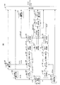
図1は、本実施の形態に係る符号化装置の構成を示すブロック図である。図1に示す符号化装置100には、PCM(Pulse Code Modulation)形式における左チャネル信号と右チャネル信号とからなるステレオ信号がフレーム毎に入力される。
FIG. 1 is a block diagram showing the configuration of the encoding apparatus according to the present embodiment. A stereo signal composed of a left channel signal and a right channel signal in a PCM (Pulse Code Modulation) format is input to the
モノラル信号合成部101は、左チャネル信号L、右チャネル信号Rを以下の式(1)により合成し、モノラル音声信号Mを生成する。モノラル信号合成部101は、左チャネル信号Lおよび右チャネル信号RをLP(Linear Prediction:線形予測)分析・量子化部102およびLP逆フィルタ103に出力し、モノラル音声信号Mをモノラル符号化部104に出力する。
![]()
![]()
この式(1)において、nは、フレームにおける時間インデックス(time index)である。なお、モノラル信号を生成するためのミックス方法は、式(1)に限定されない。例えば、適応的に重み付けしてミックスする方法等、他の方法を使用して、モノラル信号を生成することもできる。 In this equation (1), n is a time index in the frame. Note that the mixing method for generating a monaural signal is not limited to Equation (1). For example, the monaural signal can also be generated using other methods such as adaptively weighted and mixed.
LP分析・量子化部102は、左チャネル信号Lおよび右チャネル信号Rに対してLP分析(線形予測分析)によるLPパラメータの算出および算出LPパラメータの量子化を行い、得られたLPパラメータの符号化データを多重部120に出力し、LP係数AL/ARをLP逆フィルタ103に出力する。
The LP analysis /
LP逆フィルタ103は、LP係数AL/ARを用いて、左チャネル信号Lおよび右チャネル信号Rに対してLP逆フィルタリングを行い、得られた左チャネル/右チャネルの残差信号Lres/Rresをピッチ分析・量子化部105およびピッチ逆フィルタ106に出力する。
The LP
モノラル符号化部104は、モノラル信号Mを符号化し、得られた符号化データを多重部120に出力する。一方、モノラル符号化部104は、モノラル残差信号Mresをピッチ分析部107およびピッチ逆フィルタ108に出力する。なお、残差信号は励振信号ともいう。この残差信号は、ほとんどのモノラル音声符号化装置(例:CELPベースの符号化装置)において、あるいは、LP残差信号またはローカルに復号化される残差信号を生成するプロセスが含まれるタイプの符号化装置において取り出すことが可能である。
The
ピッチ分析・量子化部105は、左チャネル/右チャネルの残差信号Lres/Rresに対してピッチ分析および量子化を行い、得られた左チャネル/右チャネル残差信号のピッチパラメータ(ピッチ周期PL/PRおよびピッチ利得GL/GR)をピッチ逆フィルタ106に出力し、ピッチパラメータの符号化データを多重部120に出力する。
The pitch analysis /
ピッチ逆フィルタ106は、ピッチパラメータを用いて、左チャネル/右チャネルの残差信号Lres/Rresに対してピッチ逆フィルタリングを行い、ピッチ周期成分を除去した左チャネル/右チャネルの残差信号excL/excRを窓掛け部109に出力する。
The pitch
ピッチ分析部107は、モノラル残差信号Mresに対してピッチ分析を行い、モノラル残差信号のピッチ周期PMをピッチ逆フィルタ108に出力する。ピッチ逆フィルタ108は、ピッチ周期PMを用いて、モノラル残差信号Mresに対してピッチ逆フィルタリングを行い、ピッチ周期成分を除去したモノラル残差信号excMを窓掛け部110に出力する。
窓掛け部109は、左チャネル/右チャネルの残差信号excL/excRに対して窓掛け処理(windowing)を行い、MDCT変換部111に出力する。窓掛け部110は、モノラル残差信号excMに対して窓掛け処理を行い、MDCT変換部112に出力する。窓掛け部109および窓掛け部110の窓かけ処理に必要な正弦窓h(k)は、先行技術において幅広く使用されており、以下の式(2)によって計算される。

MDCT変換部111は、窓掛け処理後の左チャネル/右チャネルの残差信号excL/excRに対してMDCT変換を実行し、得られた左チャネル/右チャネル残差信号の周波数係数l(f)/r(f)を相関計算部113およびスペクトル分割部115に出力する。MDCT変換部112は、窓掛け処理後のモノラル残差信号excMに対してMDCT変換を実行し、得られたモノラル残差信号の周波数係数m(f)を相関計算部113およびスペクトル分割部116に出力する。なお、MDCT変換により得られた周波数係数は、一般に「MDCT係数」と呼ばれる。
The
MDCT変換部111におけるMDCT変換により得られる左チャネル残差信号の周波数係数l(f)は、以下の式(3)によって算出される。なお、この式(3)において、s(k)は長さ2Nの窓掛けされた残差信号である。なお、右チャネル残差信号の周波数係数r(f)も同様に算出される。
相関計算部113は、左チャネル残差信号の周波数係数l(f)とモノラル残差信号の周波数係数m(f)との相関値c1、右チャネル残差信号の周波数係数r(f)とモノラル残差信号の周波数係数m(f)との相関値c2をそれぞれ計算し、相関値の絶対値をICP次数割り当て部114に出力する。そして、相関計算部113は、計算結果を使用して、以下の式(4)により、分割周波数FTHを決定し、分割周波数を示す情報をスペクトル分割部115およびスペクトル分割部116に出力する。なお、式(4)により、相関が高いほど分割周波数FTHは低くなる。また、以下の説明で、分割周波数FTHより低い周波数帯域を低帯域部分、分割周波数FTH以上の周波数帯域を高帯域部分という。
式(4)において、Fsはサンプリング周波数を表す。サンプリング周波数は、16kHz、24kHz、32kHz、または48kHzとすることができる。なお、式(4)における定数「1k」および「32」は一例であり、本実施の形態では、これらの値を任意に設定することができる。 In Expression (4), Fs represents a sampling frequency. The sampling frequency can be 16 kHz, 24 kHz, 32 kHz, or 48 kHz. Note that the constants “1k” and “32” in Expression (4) are examples, and in the present embodiment, these values can be arbitrarily set.
なお、分割周波数FTHは、ビットレートに基づいて計算することもできる。例えば、所定のビットレートで符号化するために、左チャネル残差信号の周波数係数l(f)および右チャネル残差信号の周波数係数r(f)の低帯域部分について符号化できるMDCT係数の合計がX個のみであるとする。モノラル周波数係数m(f)との相関が高い方のチャネルは、符号化に必要なMDCT係数の数が少なくて済む。相関計算部113は、左チャネル残差信号の周波数係数l(f)の低帯域部分の周波数係数の数を、X×c2/(c1+c2)によって計算し、右チャネル残差信号の残差信号の周波数係数r(f)の低帯域部分の周波数係数の数を、X×c1/(c1+c2)によって計算する。
Note that the division frequency FTH can also be calculated based on the bit rate. For example, to encode at a predetermined bit rate, the sum of the MDCT coefficients that can be encoded for the low band portion of the frequency coefficient l (f) of the left channel residual signal and the frequency coefficient r (f) of the right channel residual signal Is only X. A channel having a higher correlation with the monaural frequency coefficient m (f) requires a smaller number of MDCT coefficients necessary for encoding. The
左右のチャネルのICPの次数の合計は、通常では一定である。ICP次数割り当て部114は、相関が高いほどICP次数が小さくなるように、相関値に基づいて左チャネルに割り当てるICPの次数を計算する。ICPの次数の合計をICPorとすれば、ICP次数割り当て部114は、左チャネルのICPの次数を、ICPor×c2/(c1+c2)によって計算する。なお、右チャネルのICPの次数は、ICPor×c1/(c1+c2)によって計算することができる。ICP次数割り当て部114は、左チャネルのICP次数を示す情報を、ICP分析部117および多重部120に出力する。
The sum of the ICP orders of the left and right channels is usually constant. The ICP
スペクトル分割部115は、分割周波数FTHを境として左チャネル/右チャネル残差信号の周波数係数l(f)/r(f)の帯域を分割し、その低帯域部分の周波数係数lL(f)/rL(f)を低帯域符号化部119に出力し、その高帯域部分の周波数係数lH(f)/rH(f)をICP分析部117に出力する。また、スペクトル分割部115は、低帯域符号化部119において符号化するMDCT係数の数を示す分割フラグを量子化し、多重部120に出力する。
The
スペクトル分割部116は、分割周波数FTHを境としてモノラル残差信号の周波数係数m(f)の帯域を分割し、その高帯域部分の周波数係数mH(f)をICP分析部117に出力する。
The
ICP分析部117は、適応フィルタからなり、左チャネル残差信号の高帯域部分の周波数係数lH(f)とモノラル残差信号の高帯域部分の周波数係数mH(f)との相関関係を用いてICP分析を行い、左チャネル残差信号のICPパラメータを生成する。同様に、ICP分析部117は、右チャネル残差信号の高帯域部分の周波数係数rH(f)とモノラル残差信号の高帯域部分の周波数係数mH(f)との相関関係を用いてICP分析を行い、右チャネル残差信号のICPパラメータを生成する。なお、各ICPパラメータの次数は、ICP次数割り当て部114で計算されたものとなる。ICP分析部117は、各ICPパラメータをICPパラメータ量子化部118に出力する。
The
ICPパラメータ量子化部118は、ICP分析部117から出力された各ICPパラメータを量子化し、多重部120に出力する。なお、ICPパラメータ量子化部118においてICPパラメータの量子化に使用されるビットの数も、モノラルと各チャネルとの相関によって調整することができる。この場合、相関が高いほど、ICPビット数を少なくする。総ビット数をBITと表すと、左チャネル残差信号のICPパラメータ量子化のビット数は、BIT×c2/(c1+c2)によって計算することができる。同様に、右チャネル残差信号のICPパラメータ量子化のビット数は、BIT×c1/(c1+c2
)によって計算することができる。
The ICP
) Can be calculated.
低帯域符号化部119は、左チャネル/右チャネル残差信号の低帯域部分の周波数係数lL(f)/rL(f)を符号化し、得られた符号化データを多重部120に出力する。
The low
多重部120は、LP分析・量子化部102から出力されたLPパラメータの符号化データ、モノラル符号化部104から出力されたモノラル信号の符号化データ、ピッチ分析・量子化部105から出力されたピッチパラメータの符号化データ、ICP次数割り当て部114から出力された左チャネル残差信号のICP次数を示す情報、スペクトル分割部115から出力された量子化分割フラグ、ICPパラメータ量子化部118から出力された量子化ICPパラメータ、および低帯域符号化部119から出力された左チャネル/右チャネル残差信号の低帯域部分の周波数係数の符号化データを多重し、得られたビットストリームを出力する。
The
図2は、ICP分析部117を構成する適応フィルタの構成および動作を説明するための図である。この図において、H(z)は、H(z)=b0+b1(z−1)+b2(z−2)+…+bk(z−k)であり、適応フィルタ、例えばFIR(Finite Impulse Response)フィルタのモデル(伝達関数)を示す。ここで、kは適応フィルタ係数の次数を示し、b=[b0,b1,…,bk]は適応フィルタ係数を示す。x(n)は適応フィルタの入力信号、y’(n)は適応フィルタの出力信号(予測信号)、y(n)は適応フィルタの基準信号を示す。ICP分析部117において、x(n)はmH(f)に相当し、y(n)はlH(f)またはrH(f)に相当する。
FIG. 2 is a diagram for explaining the configuration and operation of the adaptive filter that constitutes the
適応フィルタは、下記の式(5)に従って、予測信号と基準信号との平均二乗誤差(MSE)が最小となるような、適応フィルタパラメータb=[b0,b1,…,bk]を求めて出力する。なお、式(5)において、Eは統計的期待演算子(statistical expectation operator)を表し、E{.}はアンサンブル平均演算(ensemble average operation)、Kはフィルタ次数、e(n)は予測誤差を示す。
なお、図2におけるH(z)には、多数の別の構造が存在する。図3は、そのうちの1つを示している。図3に示したフィルタ構造は、従来のFIRフィルタである。 There are many other structures in H (z) in FIG. FIG. 3 shows one of them. The filter structure shown in FIG. 3 is a conventional FIR filter.
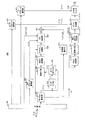
図4は、本実施の形態に係る復号装置の構成を示すブロック図である。図1に示した符号化装置100から送信されたビットストリームは、図4に示す復号装置400に受信される。
FIG. 4 is a block diagram showing a configuration of the decoding apparatus according to the present embodiment. The bit stream transmitted from the
分離部401は、復号装置400に受信されたビットストリームを分離し、LPパラメータの符号化データをLPパラメータ復号部417に出力し、ピッチパラメータの符号化データをピッチパラメータ復号部415に出力し、量子化ICPパラメータをICPパラメータ復号部403に出力し、モノラル信号の符号化データをモノラル復号部402に出力し、左チャネル残差信号のICP次数を示す情報をICP合成部409に出力し、量子化分割フラグをスペクトル分割部408に出力し、左チャネル/右チャネル残差信号の低帯域部分の周波数係数の符号化データを低帯域復号部410に出力する。
Separating
モノラル復号部402は、モノラル信号の符号化データを復号してモノラル信号M’お
よびモノラル残差信号M'resを得る。モノラル復号部402は、得られたモノラル残差信号M'resをピッチ分析部404およびピッチ逆フィルタ405に出力する。
The
ICPパラメータ復号部403は、量子化ICPパラメータを復号し、得られた左チャネル/右チャネルICPパラメータをICP合成部409に出力する。
The ICP
ピッチ分析部404は、モノラル残差信号M'resに対してピッチ分析を行い、モノラル残差信号のピッチ周期P'Mをピッチ逆フィルタ405に出力する。ピッチ逆フィルタ405は、ピッチ周期P'Mを用いて、モノラル残差信号M'resに対してピッチ逆フィルタリングを行い、ピッチ周期成分を除去したモノラル残差信号exc'Mを窓掛け部406に出力する。
窓掛け部406は、モノラル残差信号exc'Mに対して窓掛け処理を行い、MDCT変換部407に出力する。なお、窓掛け部406の窓掛け処理における窓関数は上記式(2)によって与えられる。
The
MDCT変換部407は、窓掛け処理後のモノラル残差信号exc'Mに対してMDCT変換を実行し、得られたモノラル残差信号の周波数係数m'(f)をスペクトル分割部408に出力する。なお、MDCT変換部407におけるMDCT変換の計算は上記式(3)によって与えられる。
The MDCT conversion unit 407 performs MDCT conversion on the monaural residual signal exc ′ M after the windowing process, and outputs the frequency coefficient m ′ (f) of the obtained monaural residual signal to the
スペクトル分割部408は、分割周波数FTHを境として全帯域を分割した後、モノラル残差信号の高帯域部分の周波数係数m'H(f)をICP合成部409に出力する。
The
ICP合成部409は、適応フィルタからなり、左チャネルのICPパラメータを用いてモノラル残差信号の高帯域部分の周波数係数m'H(f)をフィルタリングすることにより、左チャネル残差信号の高帯域部分の周波数係数l'H(f)を計算する。同様に、ICP合成部409は、右チャネルのICPパラメータを用いてモノラル残差信号の高帯域部分の周波数係数m'H(f)をフィルタリングすることにより、右チャネル残差信号の高帯域部分の周波数係数r'H(f)を計算する。ICP合成部409は、左チャネル/右チャネル残差信号の高帯域部分の周波数係数l'H(f)/r'H(f)を加算部411に出力する。
The
なお、左チャネル残差信号の高帯域部分の周波数係数l'H(f)は、以下の式(6)によって計算することができる。なお、式(6)において、bi Lは、左チャネルの再生成されたICPパラメータの第i次の要素である。Kは、左チャネルのICP次数を示す情報によって得られる。なお、右チャネル残差信号の高帯域部分の周波数係数r'H(f)も同様に計算することができる。
低帯域復号部410は、左チャネル/右チャネル残差信号の低帯域部分の周波数係数の符号化データを復号し、得られた左チャネル/右チャネル残差信号の低帯域部分の周波数係数lL'(f)/rL'(f)を加算部411に出力する。
The low
加算部411は、左チャネル/右チャネル残差信号の低帯域部分の周波数係数lL'(f)/rL'(f)と左チャネル/右チャネル残差信号の高帯域部分の周波数係数l'H(f)/r'H(f)とを結合し、得られた左チャネル/右チャネル残差信号の周波数係数
l'(f)/r'(f)をIMDCT変換部412に出力する。
The
IMDCT変換部412は、左チャネル/右チャネル残差信号の周波数係数l'(f)/r'(f)に対してIMDCT変換を実行する。左チャネル残差信号の周波数係数l'(f)に対するIMDCT変換の計算は、以下の式(7)によって行われる。ここで、式(7)において、s(k)は、時間領域エイリアシングを含んでいるIMDCT係数である。なお、右チャネル残差信号の周波数係数r'(f)に対するIMDCT変換の計算も同様に行われる。
左チャネル/右チャネル残差信号を再生成するため、窓掛け部413が、IMDCT変換部412の出力信号に対して窓掛け処理を行い、重ね合わせ加算部414が、窓掛け部413の出力信号に対して重ね合わせ加算(overlap and add)を行い、左チャネル/右チャネルの残差信号exc'L/exc'Rを得る。再生成された左チャネル/右チャネルの残差信号exc'L/exc'Rは、ピッチ合成部416に出力される。
In order to regenerate the left channel / right channel residual signal, the
ピッチパラメータ復号部415は、ピッチパラメータの符号化データを復号し、得られた左チャネル/右チャネル残差信号のピッチパラメータ(ピッチ周期PL/PRおよびピッチ利得GL/GR)をピッチ合成部416に出力する。
Pitch parameter decoding section 415 decodes the encoded data of pitch parameter, pitch parameter obtained left channel / right channel residual signal (pitch period P L / P R and pitch gain G L / G R) pitch The data is output to the combining
ピッチ合成部416は、左チャネル/右チャネルの残差信号exc'L/exc'Rに対して、ピッチ周期PL/PRおよびピッチ利得GL/GRを用いてピッチ合成フィルタリングを行い、得られた左チャネル/右チャネル残差信号L'res/R'resをLP合成フィルタ418に出力する。
LPパラメータ復号部417は、LPパラメータの符号化データを復号し、得られたLP係数AL/ARをLP合成フィルタ418に出力する。
The LP
LP合成フィルタ418は、左チャネル/右チャネル残差信号L'res/R'resに対して、LP係数AL/ARを用いてLP合成フィルタリングを行い、左チャネル信号L'および右チャネル信号R'を得る。
The
このように、図4の復号装置400は、受信した図1の符号化装置100の信号に対して復号処理を行うことにより、モノラル信号M’とステレオ音声信号L'/R'の両方を得ることができる。
As described above, the
以上のように、本実施の形態によれば、聴感上、重要度が相対的に高い低帯域部分に対して高い量子化精度の符号化方法を用い、重要度が相対的に低い高帯域部分に対してICPを用いた効率の高い符号化方法を用いることにより、符号化・復号の高効率化と復号音声の高品質化の両方を実現することができる。 As described above, according to the present embodiment, an encoding method with high quantization accuracy is used for a low-band portion that is relatively high in terms of audibility, and a high-band portion that is relatively low in importance. On the other hand, by using a highly efficient encoding method using ICP, it is possible to realize both high efficiency of encoding / decoding and high quality of decoded speech.
また、本実施の形態によれば、MDCT変換符号化器によってMDCT領域で復号されたモノラル信号をICPプロセスに使用することにより、ICPがMDCT領域において直接実行されるため、アルゴリズムに起因する追加の遅延が発生しない。 In addition, according to the present embodiment, since the monaural signal decoded in the MDCT domain by the MDCT transform encoder is used in the ICP process, the ICP is directly executed in the MDCT domain. There is no delay.
(その他の実施の形態)
本発明は、実施の形態1において、ピッチ分析およびピッチフィルタリングに関連する
図1のブロック105、106、107、108、図4のブロック404、405、415、416を省いても、依然として使用することができる。
(Other embodiments)
In the first embodiment, the present invention is still used even if the
また、実施の形態1において、スペクトル分割部115、116で使用される適応的な周波数分割器を、分割周波数が固定のものに変更することができる。この場合、分割周波数を、例えば1kHz等、任意に設定する。
In Embodiment 1, the adaptive frequency divider used in
また、実施の形態1において、ICP次数割り当て部114における適応的なICP次数の計算、ICPパラメータ量子化部118におけるICPパラメータの適応的なビット割り当てを、それぞれ、固定のICP次数、固定のビット割り当てに変更することができる。
Further, in the first embodiment, the calculation of the adaptive ICP order in the ICP
また、実施の形態1において、モノラル符号器がMDCT変換符号化などの変換符号化である場合、MDCT領域における復号モノラル信号(または復号モノラル残差信号)を、符号器側においてはモノラル符号器から、復号器側においてはモノラル復号器から、直接得ることができる。すなわち、実施の形態1において、符号器側では、図1のブロック107、108、110、112を省略し、MDCT変換部112からの出力であるモノラル残差信号の周波数係数m(f)の代わりに、モノラル符号化部104から復号モノラル残差信号の周波数係数を直接得るようにすることができる。また、復号器側では、図4のブロック404、405、406、407を省略し、MDCT変換部407からの出力であるモノラル残差信号の周波数係数m'(f)の代わりに、モノラル復号部402から復号モノラル残差信号の周波数係数を直接得るようにすることができる。
In the first embodiment, when the monaural encoder is transform coding such as MDCT transform coding, the decoded monaural signal (or decoded monaural residual signal) in the MDCT domain is transmitted from the monaural encoder on the encoder side. On the decoder side, it can be obtained directly from the monaural decoder. That is, in the first embodiment, the
また、上述したように、本発明は、PCM形式の音声信号に適用することができる。そして、本発明は、LPフィルタリングおよびピッチフィルタリングを省いても、依然として使用することができる。この場合、窓掛けされたモノラルおよび左/右チャネルの音声信号をMDCT領域に変換する。MDCT係数の高帯域部分をICPによって符号化する。低帯域部分は、高精度の符号器によって符号化する。復号器側において、伝送された低帯域部分と、ICP合成により再生成された高帯域部分とを結合して、左/右のチャネルの音声信号のMDCT係数を再生成する。その後、IMDCT、窓掛け、重ね合わせ加算することにより、合成された音声信号を得ることができる。 Further, as described above, the present invention can be applied to a PCM format audio signal. The present invention can still be used even if LP filtering and pitch filtering are omitted. In this case, the windowed monaural and left / right channel audio signals are converted to the MDCT domain. The high band part of the MDCT coefficient is encoded by ICP. The low band part is encoded by a high precision encoder. On the decoder side, the transmitted low band part and the high band part regenerated by ICP synthesis are combined to regenerate the MDCT coefficients of the audio signal of the left / right channel. Thereafter, the synthesized speech signal can be obtained by IMDCT, windowing, and overlay addition.
また、上記実施の形態1において説明した符号化方式は、モノラル残差信号を使用して左/右のチャネルの残差信号を再生成する方式であり、この方式をM−LR符号化方式と呼ぶことができる。本発明は、これとは別のM−S符号化方式と呼ばれる符号化方式を採用することができる。この代替方式においては、モノラル残差信号を使用してサイド残差信号を再生成することができる。この場合の符号器側の構成は、実施の形態1におけるM−LR符号化方式の符号器側ブロック図1とほぼ同じであるが、左右のチャンネル信号に対する処理ブロックである102、103、105、106、109、111、115、119を、サイドチャンネル信号用の処理に置き換えたものになる。また、サイド音声信号S(n)は、モノラル信号合成部101において、以下の式(8)によって計算することによって算出する。なお、式(8)において、nは長さNのフレームにおける時間インデックスである。また、復号器側の構成は、実施の形態1における図4とほぼ同じであるが、左右のチャンネル信号に対する処理ブロックである409、410、411、412、413、415、416、417、418を、サイドチャンネル信号用の処理に置き換えたものになる。
![]()
![]()
さらに、復号器において、左右のチャネルの合成された音声信号(L’およびR’)は、再生成されたサイド信号S’と、再生成されたモノラル信号M’とを使用することによって、以下の式(9)によって算出される。
![]()
![]()
また、本発明は、MDCT計算によって得られた全帯域の周波数係数すべてに対して、共通な1つのICPプロセスを適用することができる。この場合、ICP予測誤差信号(特に低帯域部分における予測誤差信号)を符号化して送信することが望ましい。 Further, the present invention can apply one common ICP process to all the frequency coefficients of the entire band obtained by MDCT calculation. In this case, it is desirable to encode and transmit an ICP prediction error signal (especially a prediction error signal in a low band portion).
また、本発明は、MDCT計算の後、周波数係数をk(>2)個のサブ帯域に分割し、サブ帯域それぞれに対してICP分析を個々に行うことができる。各サブ帯域に対するICPパラメータ数(ICP次数)は異なっていてよい。この数は、相関値やサブ帯域の位置に依存する。一般的には、高い周波数サブ帯域ほど、ICPパラメータ数を少なくする。あるいは、本発明は、各サブ帯域のビット割り当てを適応的に制御するようにしてもよい。 In addition, according to the present invention, after MDCT calculation, the frequency coefficient is divided into k (> 2) subbands, and ICP analysis can be individually performed on each of the subbands. The number of ICP parameters (ICP order) for each subband may be different. This number depends on the correlation value and the position of the sub-band. In general, the higher the frequency sub-band, the smaller the number of ICP parameters. Alternatively, the present invention may adaptively control the bit allocation of each subband.
また、上記実施の形態1では、ICPの計算を上記式(5)によって行い、フィルタの構造として図3に示したものを使用している。本発明は、これに代えて、この片側ICPを両側ICPに変更し、式(5)における予測信号y’(n)の計算を、以下の式(10)に置き換えることができる。この場合、ICP次数はN1+N2となる(N1、N2はいずれも正の定数)。
また、上記本実施の形態では、MDCT変換を用いて周波数領域への変換を行う場合について説明したが、本発明はこれに限られず、MDCT変換の代わりに、高速フーリエ変換(FFT)等の他の周波数変換方式を用いて周波数領域への変換を行っても良い。 In the above-described embodiment, the case where the conversion to the frequency domain is performed using the MDCT transform has been described. However, the present invention is not limited to this, and other than the MDCT transform, such as Fast Fourier Transform (FFT). Conversion to the frequency domain may be performed using this frequency conversion method.
また、本発明では、ICP分析部117において使用するICP計算において誤差重み付けを適用して、心理音響(Psychoacoustic)を考慮することができる。これは、上記式(5)においてE[e2(f)]の代わりにE[e2(f)×w(f)]を最小化することで実現することができる。ここで、w(f)は心理音響モデルから導かれる重み付け係数である。この重み付け係数は、エネルギの高い周波数(または帯域)に対しては小さい重み、エネルギの低い周波数(または帯域)に対しては大きい重みを乗ずることによって、予測誤差を調整するように使用する。例えば、w(f)は、mH(f)のエネルギに反比例する重み付け係数とすることができる。従って、w(f)の1つの可能な形式は、以下の式(11)である(α,βは調整パラメータ)。
なお、上記各実施の形態に係る復号装置は、上記各実施の形態に係る符号化装置が送信したビットストリームを受信して処理を行う場合を例にとって説明したが、本発明はこれに限定されず、上記各実施の形態に係る復号装置が受信して処理するビットストリームは
、この復号装置で処理可能なビットストリームを生成可能な符号化装置が送信したものであれば良い。
Note that the decoding apparatus according to each of the above embodiments has been described with respect to an example in which the bitstream transmitted by the encoding apparatus according to each of the above embodiments is received and processed, but the present invention is not limited thereto. Instead, the bitstream received and processed by the decoding apparatus according to each of the above embodiments may be any bitstream transmitted by an encoding apparatus that can generate a bitstream that can be processed by this decoding apparatus.
なお、以上の説明は本発明の好適な実施の形態の例証であり、本発明の範囲はこれに限定されることはない。本発明は、符号化装置、復号装置を有するシステムであればどのような場合にも適用することができる。 The above description is an illustration of a preferred embodiment of the present invention, and the scope of the present invention is not limited to this. The present invention can be applied to any system as long as the system includes an encoding device and a decoding device.
また、本発明に係る符号化装置および復号装置は、移動体通信システムにおける通信端末装置および基地局装置に搭載することが可能であり、これにより上記と同様の作用効果を有する通信端末装置、基地局装置、および移動体通信システムを提供することができる。 Also, the encoding device and the decoding device according to the present invention can be mounted on a communication terminal device and a base station device in a mobile communication system, whereby a communication terminal device and a base having the same operational effects as described above. A station apparatus and a mobile communication system can be provided.
また、ここでは、本発明をハードウェアで構成する場合を例にとって説明したが、本発明をソフトウェアで実現することも可能である。例えば、本発明に係るアルゴリズムをプログラミング言語によって記述し、このプログラムをメモリに記憶しておいて情報処理手段によって実行させることにより、本発明に係る符号化装置と同様の機能を実現することができる。 Further, here, the case where the present invention is configured by hardware has been described as an example, but the present invention can also be realized by software. For example, a function similar to that of the encoding apparatus according to the present invention can be realized by describing the algorithm according to the present invention in a programming language, storing the program in a memory, and causing the information processing means to execute the program. .
また、上記実施の形態の説明に用いた各機能ブロックは、典型的には集積回路であるLSIとして実現される。これらは個別に1チップ化されても良いし、一部または全てを含むように1チップ化されても良い。 Each functional block used in the description of the above embodiment is typically realized as an LSI which is an integrated circuit. These may be individually made into one chip, or may be made into one chip so as to include a part or all of them.
また、ここではLSIとしたが、集積度の違いによって、IC、システムLSI、スーパーLSI、ウルトラLSI等と呼称されることもある。 Although referred to as LSI here, it may be called IC, system LSI, super LSI, ultra LSI, or the like depending on the degree of integration.
また、集積回路化の手法はLSIに限るものではなく、専用回路または汎用プロセッサで実現しても良い。LSI製造後に、プログラム化することが可能なFPGA(Field Programmable Gate Array)や、LSI内部の回路セルの接続もしくは設定を再構成可能なリコンフィギュラブル・プロセッサを利用しても良い。 Further, the method of circuit integration is not limited to LSI's, and implementation using dedicated circuitry or general purpose processors is also possible. An FPGA (Field Programmable Gate Array) that can be programmed after manufacturing the LSI or a reconfigurable processor that can reconfigure the connection or setting of circuit cells inside the LSI may be used.
さらに、半導体技術の進歩または派生する別技術により、LSIに置き換わる集積回路化の技術が登場すれば、当然、その技術を用いて機能ブロックの集積化を行っても良い。バイオ技術の適用等が可能性としてあり得る。 Further, if integrated circuit technology comes out to replace LSI's as a result of the advancement of semiconductor technology or a derivative other technology, it is naturally also possible to carry out function block integration using this technology. Biotechnology can be applied as a possibility.
2007年3月30日出願の特願2007−092751の日本出願に含まれる明細書、図面および要約書の開示内容は、すべて本願に援用される。 The disclosure of the specification, drawings and abstract contained in the Japanese application of Japanese Patent Application No. 2007-092751 filed on Mar. 30, 2007 is incorporated herein by reference.
本発明に係る符号化装置および符号化方法は、携帯電話、IP電話、テレビ会議等に用いるに好適である。 The encoding apparatus and encoding method according to the present invention are suitable for use in mobile phones, IP phones, video conferences, and the like.
Claims (5)
前記第1チャネル残差信号および前記第2チャネル残差信号をそれぞれ周波数領域に変換し、第1チャネル周波数係数および第2チャネル周波数係数を得る周波数領域変換手段と、
第1の符号化方法を用いて、前記第1チャネル周波数係数および第2チャネル周波数係数の閾値周波数未満の帯域部分に対して符号化を行う第1符号化手段と、
チャネル間予測分析および前記第1の符号化方法より効率の高い第2の符号化方法を用いて、前記第1チャネル周波数係数および第2チャネル周波数係数の前記閾値周波数以上の帯域部分に対して符号化を行う第2符号化手段と、
を具備する符号化装置。 Residual signal acquisition means for acquiring a first channel residual signal and a second channel residual signal, which are linear prediction residual signals for the first channel signal and the second channel signal of the stereo signal;
Frequency domain transforming means for transforming the first channel residual signal and the second channel residual signal into frequency domains, respectively, to obtain a first channel frequency coefficient and a second channel frequency coefficient;
First encoding means for performing encoding on a band portion of the first channel frequency coefficient and the second channel frequency coefficient that are less than a threshold frequency using a first encoding method;
Code is applied to band portions of the first channel frequency coefficient and the second channel frequency coefficient that are equal to or higher than the threshold frequency using inter-channel prediction analysis and a second encoding method that is more efficient than the first encoding method. Second encoding means for performing
An encoding device comprising:
前記第2符号化手段は、前記第1チャネル周波数係数と前記モノラル周波数係数との相関関係および前記第2チャネル周波数係数と前記モノラル周波数係数との相関関係に基づいて前記チャネル間予測分析を行い、前記チャネル間予測分析によって得られた前記第1チャネルおよび前記第2チャネルの予測パラメータを量子化する、
請求項1記載の符号化装置。 Further comprising second frequency domain transform means for transforming a linear prediction residual signal for a monaural signal generated from the stereo signal into a frequency domain to obtain a monaural frequency coefficient;
Said second coding means performs prediction analysis between the channel based on the correlation between the monaural frequency coefficient correlation and the second channel frequency coefficient between the said first channel frequency coefficient monaural frequency coefficients, quantizes the prediction parameters obtained the first channel and the second channel by the predictive analysis between said channel,
The encoding device according to claim 1.
請求項2記載の符号化装置。 The second encoding means calculates the threshold frequency based on a first correlation value between the first channel frequency coefficient and the monaural frequency coefficient and a second correlation value between the second channel frequency coefficient and the monaural frequency coefficient. Comprising threshold frequency setting means for setting;
The encoding device according to claim 2.
請求項2記載の符号化装置。 Prediction codes of the first channel and the second channel based on a first correlation value between the first channel frequency coefficient and the monaural frequency coefficient and a second correlation value between the second channel frequency coefficient and the monaural frequency coefficient Further comprising an order assigning means for assigning the order of the optimization parameters;
The encoding device according to claim 2.
前記第1チャネル残差信号および前記第2チャネル残差信号をそれぞれ周波数領域に変換し、第1チャネル周波数係数および第2チャネル周波数係数を得る周波数領域変換ステップと、
第1の符号化方法を用いて、前記第1チャネル周波数係数および第2チャネル周波数係数の閾値周波数未満の帯域部分に対して符号化を行う第1符号化ステップと、
チャネル間予測分析および前記第1の符号化方法より効率の高い第2の符号化方法を用いて、前記第1チャネル周波数係数および第2チャネル周波数係数の前記閾値周波数以上の帯域部分に対して符号化を行う第2符号化ステップと、
を有する符号化方法。
A residual signal acquisition step of acquiring a first channel residual signal and a second channel residual signal which are linear prediction residual signals for the first channel signal and the second channel signal of the stereo signal;
A frequency domain transforming step of transforming the first channel residual signal and the second channel residual signal into frequency domains, respectively, to obtain a first channel frequency coefficient and a second channel frequency coefficient;
A first encoding step of performing encoding on a band portion of the first channel frequency coefficient and the second channel frequency coefficient that are less than a threshold frequency using a first encoding method;
Code is applied to band portions of the first channel frequency coefficient and the second channel frequency coefficient that are equal to or higher than the threshold frequency using inter-channel prediction analysis and a second encoding method that is more efficient than the first encoding method. A second encoding step for performing
An encoding method comprising:
Priority Applications (1)
| Application Number | Priority Date | Filing Date | Title |
|---|---|---|---|
| JP2009508902A JP5355387B2 (en) | 2007-03-30 | 2008-03-28 | Encoding apparatus and encoding method |
Applications Claiming Priority (4)
| Application Number | Priority Date | Filing Date | Title |
|---|---|---|---|
| JP2007092751 | 2007-03-30 | ||
| JP2007092751 | 2007-03-30 | ||
| JP2009508902A JP5355387B2 (en) | 2007-03-30 | 2008-03-28 | Encoding apparatus and encoding method |
| PCT/JP2008/000808 WO2008126382A1 (en) | 2007-03-30 | 2008-03-28 | Encoding device and encoding method |
Publications (2)
| Publication Number | Publication Date |
|---|---|
| JPWO2008126382A1 JPWO2008126382A1 (en) | 2010-07-22 |
| JP5355387B2 true JP5355387B2 (en) | 2013-11-27 |
Family
ID=39863542
Family Applications (1)
| Application Number | Title | Priority Date | Filing Date |
|---|---|---|---|
| JP2009508902A Expired - Fee Related JP5355387B2 (en) | 2007-03-30 | 2008-03-28 | Encoding apparatus and encoding method |
Country Status (6)
| Country | Link |
|---|---|
| US (1) | US8983830B2 (en) |
| EP (1) | EP2133872B1 (en) |
| JP (1) | JP5355387B2 (en) |
| AT (1) | ATE547786T1 (en) |
| BR (1) | BRPI0809940A2 (en) |
| WO (1) | WO2008126382A1 (en) |
Families Citing this family (9)
| Publication number | Priority date | Publication date | Assignee | Title |
|---|---|---|---|---|
| BRPI0809940A2 (en) * | 2007-03-30 | 2014-10-07 | Panasonic Corp | CODING DEVICE AND CODING METHOD |
| WO2009153995A1 (en) * | 2008-06-19 | 2009-12-23 | パナソニック株式会社 | Quantizer, encoder, and the methods thereof |
| EP2434483A4 (en) * | 2009-05-20 | 2016-04-27 | Panasonic Ip Corp America | Encoding device, decoding device, and methods therefor |
| JP5581449B2 (en) * | 2010-08-24 | 2014-08-27 | ドルビー・インターナショナル・アーベー | Concealment of intermittent mono reception of FM stereo radio receiver |
| CN102208188B (en) | 2011-07-13 | 2013-04-17 | 华为技术有限公司 | Audio signal encoding-decoding method and device |
| CN102522092B (en) * | 2011-12-16 | 2013-06-19 | 大连理工大学 | Device and method for expanding speech bandwidth based on G.711.1 |
| US10217468B2 (en) * | 2017-01-19 | 2019-02-26 | Qualcomm Incorporated | Coding of multiple audio signals |
| WO2018189414A1 (en) * | 2017-04-10 | 2018-10-18 | Nokia Technologies Oy | Audio coding |
| US10431231B2 (en) * | 2017-06-29 | 2019-10-01 | Qualcomm Incorporated | High-band residual prediction with time-domain inter-channel bandwidth extension |
Citations (2)
| Publication number | Priority date | Publication date | Assignee | Title |
|---|---|---|---|---|
| JPH0787033A (en) * | 1993-09-17 | 1995-03-31 | Sharp Corp | Stereo audio signal coder |
| JPH0865169A (en) * | 1994-06-13 | 1996-03-08 | Sony Corp | Coding method and coder, decoder and recording medium |
Family Cites Families (36)
| Publication number | Priority date | Publication date | Assignee | Title |
|---|---|---|---|---|
| DE3276651D1 (en) * | 1982-11-26 | 1987-07-30 | Ibm | Speech signal coding method and apparatus |
| US5172415A (en) * | 1990-06-08 | 1992-12-15 | Fosgate James W | Surround processor |
| DE4320990B4 (en) | 1993-06-05 | 2004-04-29 | Robert Bosch Gmbh | Redundancy reduction procedure |
| EP0688113A2 (en) | 1994-06-13 | 1995-12-20 | Sony Corporation | Method and apparatus for encoding and decoding digital audio signals and apparatus for recording digital audio |
| EP0820624A1 (en) * | 1995-04-10 | 1998-01-28 | Corporate Computer Systems, Inc. | System for compression and decompression of audio signals for digital transmission |
| US5774837A (en) * | 1995-09-13 | 1998-06-30 | Voxware, Inc. | Speech coding system and method using voicing probability determination |
| US5812971A (en) | 1996-03-22 | 1998-09-22 | Lucent Technologies Inc. | Enhanced joint stereo coding method using temporal envelope shaping |
| SE512719C2 (en) * | 1997-06-10 | 2000-05-02 | Lars Gustaf Liljeryd | A method and apparatus for reducing data flow based on harmonic bandwidth expansion |
| DE19730130C2 (en) * | 1997-07-14 | 2002-02-28 | Fraunhofer Ges Forschung | Method for coding an audio signal |
| DE69836785T2 (en) * | 1997-10-03 | 2007-04-26 | Matsushita Electric Industrial Co., Ltd., Kadoma | Audio signal compression, speech signal compression and speech recognition |
| GB9811019D0 (en) * | 1998-05-21 | 1998-07-22 | Univ Surrey | Speech coders |
| SE519552C2 (en) | 1998-09-30 | 2003-03-11 | Ericsson Telefon Ab L M | Multichannel signal coding and decoding |
| FR2791167B1 (en) * | 1999-03-17 | 2003-01-10 | Matra Nortel Communications | AUDIO ENCODING, DECODING AND TRANSCODING METHODS |
| US6446037B1 (en) * | 1999-08-09 | 2002-09-03 | Dolby Laboratories Licensing Corporation | Scalable coding method for high quality audio |
| JP2002052798A (en) | 2000-08-08 | 2002-02-19 | Riso Kagaku Corp | Stencil printer |
| US6937978B2 (en) * | 2001-10-30 | 2005-08-30 | Chungwa Telecom Co., Ltd. | Suppression system of background noise of speech signals and the method thereof |
| CN100508026C (en) * | 2002-04-10 | 2009-07-01 | 皇家飞利浦电子股份有限公司 | Coding of stereo signals |
| US7191136B2 (en) * | 2002-10-01 | 2007-03-13 | Ibiquity Digital Corporation | Efficient coding of high frequency signal information in a signal using a linear/non-linear prediction model based on a low pass baseband |
| US7809579B2 (en) * | 2003-12-19 | 2010-10-05 | Telefonaktiebolaget Lm Ericsson (Publ) | Fidelity-optimized variable frame length encoding |
| US20050159942A1 (en) * | 2004-01-15 | 2005-07-21 | Manoj Singhal | Classification of speech and music using linear predictive coding coefficients |
| DE102004009954B4 (en) * | 2004-03-01 | 2005-12-15 | Fraunhofer-Gesellschaft zur Förderung der angewandten Forschung e.V. | Apparatus and method for processing a multi-channel signal |
| US8204261B2 (en) * | 2004-10-20 | 2012-06-19 | Fraunhofer-Gesellschaft Zur Foerderung Der Angewandten Forschung E.V. | Diffuse sound shaping for BCC schemes and the like |
| SE0402651D0 (en) * | 2004-11-02 | 2004-11-02 | Coding Tech Ab | Advanced methods for interpolation and parameter signaling |
| BRPI0607303A2 (en) | 2005-01-26 | 2009-08-25 | Matsushita Electric Ind Co Ltd | voice coding device and voice coding method |
| ATE521143T1 (en) * | 2005-02-23 | 2011-09-15 | Ericsson Telefon Ab L M | ADAPTIVE BIT ALLOCATION FOR MULTI-CHANNEL AUDIO ENCODING |
| US9626973B2 (en) * | 2005-02-23 | 2017-04-18 | Telefonaktiebolaget L M Ericsson (Publ) | Adaptive bit allocation for multi-channel audio encoding |
| ES2623551T3 (en) | 2005-03-25 | 2017-07-11 | Iii Holdings 12, Llc | Sound coding device and sound coding procedure |
| KR101259203B1 (en) | 2005-04-28 | 2013-04-29 | 파나소닉 주식회사 | Audio encoding device and audio encoding method |
| RU2007139784A (en) | 2005-04-28 | 2009-05-10 | Мацусита Электрик Индастриал Ко., Лтд. (Jp) | AUDIO ENCODING DEVICE AND AUDIO ENCODING METHOD |
| US20070055510A1 (en) * | 2005-07-19 | 2007-03-08 | Johannes Hilpert | Concept for bridging the gap between parametric multi-channel audio coding and matrixed-surround multi-channel coding |
| US7765104B2 (en) * | 2005-08-30 | 2010-07-27 | Lg Electronics Inc. | Slot position coding of residual signals of spatial audio coding application |
| US7523602B2 (en) | 2005-09-27 | 2009-04-28 | United Technologies Corporation | Turbine exhaust catalyst |
| US8112286B2 (en) * | 2005-10-31 | 2012-02-07 | Panasonic Corporation | Stereo encoding device, and stereo signal predicting method |
| US8285556B2 (en) * | 2006-02-07 | 2012-10-09 | Lg Electronics Inc. | Apparatus and method for encoding/decoding signal |
| EP1990800B1 (en) | 2006-03-17 | 2016-11-16 | Panasonic Intellectual Property Management Co., Ltd. | Scalable encoding device and scalable encoding method |
| BRPI0809940A2 (en) * | 2007-03-30 | 2014-10-07 | Panasonic Corp | CODING DEVICE AND CODING METHOD |
-
2008
- 2008-03-28 BR BRPI0809940-5A2A patent/BRPI0809940A2/en not_active Application Discontinuation
- 2008-03-28 AT AT08720675T patent/ATE547786T1/en active
- 2008-03-28 WO PCT/JP2008/000808 patent/WO2008126382A1/en active Application Filing
- 2008-03-28 US US12/593,033 patent/US8983830B2/en not_active Expired - Fee Related
- 2008-03-28 EP EP08720675A patent/EP2133872B1/en not_active Not-in-force
- 2008-03-28 JP JP2009508902A patent/JP5355387B2/en not_active Expired - Fee Related
Patent Citations (2)
| Publication number | Priority date | Publication date | Assignee | Title |
|---|---|---|---|---|
| JPH0787033A (en) * | 1993-09-17 | 1995-03-31 | Sharp Corp | Stereo audio signal coder |
| JPH0865169A (en) * | 1994-06-13 | 1996-03-08 | Sony Corp | Coding method and coder, decoder and recording medium |
Non-Patent Citations (2)
| Title |
|---|
| CSNG200501445001; 鎌本 優: 'チャネル間相関を用いた多チャネル信号の可逆圧縮符号化' 情報処理学会論文誌 第46巻 第5号 , 2005, 社団法人情報処理学会 * |
| JPN6013018257; 鎌本 優: 'チャネル間相関を用いた多チャネル信号の可逆圧縮符号化' 情報処理学会論文誌 第46巻 第5号 , 2005, 社団法人情報処理学会 * |
Also Published As
| Publication number | Publication date |
|---|---|
| EP2133872A4 (en) | 2010-12-22 |
| EP2133872A1 (en) | 2009-12-16 |
| ATE547786T1 (en) | 2012-03-15 |
| WO2008126382A1 (en) | 2008-10-23 |
| JPWO2008126382A1 (en) | 2010-07-22 |
| US20100106493A1 (en) | 2010-04-29 |
| US8983830B2 (en) | 2015-03-17 |
| BRPI0809940A2 (en) | 2014-10-07 |
| EP2133872B1 (en) | 2012-02-29 |
Similar Documents
| Publication | Publication Date | Title |
|---|---|---|
| JP5355387B2 (en) | Encoding apparatus and encoding method | |
| JP5413839B2 (en) | Encoding device and decoding device | |
| JP6705787B2 (en) | Decoding device, decoding method, and computer program | |
| JP6170520B2 (en) | Audio and / or speech signal encoding and / or decoding method and apparatus | |
| KR101340233B1 (en) | Stereo encoding device, stereo decoding device, and stereo encoding method | |
| CN105702258B (en) | Method and apparatus for encoding and decoding audio signal | |
| JP5096468B2 (en) | Free shaping of temporal noise envelope without side information | |
| JP5404412B2 (en) | Encoding device, decoding device and methods thereof | |
| WO2012066727A1 (en) | Stereo signal encoding device, stereo signal decoding device, stereo signal encoding method, and stereo signal decoding method | |
| JP2009527017A (en) | Apparatus for perceptual weighting in audio encoding / decoding | |
| KR20090007396A (en) | Method and apparatus for lossless encoding of a source signal, using a lossy encoded data stream and a lossless extension data stream | |
| CN102150202A (en) | Method and apparatus to encode and decode an audio/speech signal | |
| WO2013168414A1 (en) | Hybrid audio signal encoder, hybrid audio signal decoder, method for encoding audio signal, and method for decoding audio signal | |
| WO2006041055A1 (en) | Scalable encoder, scalable decoder, and scalable encoding method | |
| US20100121632A1 (en) | Stereo audio encoding device, stereo audio decoding device, and their method | |
| WO2009048239A2 (en) | Encoding and decoding method using variable subband analysis and apparatus thereof | |
| JPWO2006129615A1 (en) | Scalable encoding apparatus and scalable encoding method | |
| JPWO2008132826A1 (en) | Stereo speech coding apparatus and stereo speech coding method | |
| JPWO2008090970A1 (en) | Stereo encoding apparatus, stereo decoding apparatus, and methods thereof | |
| WO2022009505A1 (en) | Coding apparatus, decoding apparatus, coding method, decoding method, and hybrid coding system | |
| Herre et al. | Perceptual audio coding of speech signals | |
| Herre et al. | 18. Perceptual Perceptual Audio Coding of Speech Signals | |
| KR20120089230A (en) | Apparatus for decoding a signal | |
| KR20130012972A (en) | Method of encoding audio/speech signal |
Legal Events
| Date | Code | Title | Description |
|---|---|---|---|
| A131 | Notification of reasons for refusal |
Free format text: JAPANESE INTERMEDIATE CODE: A131 Effective date: 20130423 |
|
| A521 | Request for written amendment filed |
Free format text: JAPANESE INTERMEDIATE CODE: A523 Effective date: 20130620 |
|
| TRDD | Decision of grant or rejection written | ||
| A01 | Written decision to grant a patent or to grant a registration (utility model) |
Free format text: JAPANESE INTERMEDIATE CODE: A01 Effective date: 20130806 |
|
| A61 | First payment of annual fees (during grant procedure) |
Free format text: JAPANESE INTERMEDIATE CODE: A61 Effective date: 20130827 |
|
| R150 | Certificate of patent or registration of utility model |
Free format text: JAPANESE INTERMEDIATE CODE: R150 |
|
| S111 | Request for change of ownership or part of ownership |
Free format text: JAPANESE INTERMEDIATE CODE: R313113 |
|
| R350 | Written notification of registration of transfer |
Free format text: JAPANESE INTERMEDIATE CODE: R350 |
|
| S111 | Request for change of ownership or part of ownership |
Free format text: JAPANESE INTERMEDIATE CODE: R313113 |
|
| R350 | Written notification of registration of transfer |
Free format text: JAPANESE INTERMEDIATE CODE: R350 |
|
| LAPS | Cancellation because of no payment of annual fees |