JP5353232B2 - Electronic blood pressure monitor - Google Patents
Electronic blood pressure monitor Download PDFInfo
- Publication number
- JP5353232B2 JP5353232B2 JP2008331054A JP2008331054A JP5353232B2 JP 5353232 B2 JP5353232 B2 JP 5353232B2 JP 2008331054 A JP2008331054 A JP 2008331054A JP 2008331054 A JP2008331054 A JP 2008331054A JP 5353232 B2 JP5353232 B2 JP 5353232B2
- Authority
- JP
- Japan
- Prior art keywords
- measurement
- voltage
- consumption
- battery
- measurable
- Prior art date
- Legal status (The legal status is an assumption and is not a legal conclusion. Google has not performed a legal analysis and makes no representation as to the accuracy of the status listed.)
- Active
Links
Images


Landscapes
- Measuring Pulse, Heart Rate, Blood Pressure Or Blood Flow (AREA)
Abstract
Description
本発明は、電子血圧計に関し、特に、電池を備えた電子血圧計に関する。 The present invention relates to an electronic sphygmomanometer, and more particularly to an electronic sphygmomanometer including a battery.
毎日血圧を測定することは、健康管理の上で非常に重要である。そのために、院外でも血圧を測定できる家庭用の電子血圧計が普及している。 Measuring blood pressure daily is very important for health care. For this reason, home-use electronic blood pressure monitors that can measure blood pressure outside the hospital have become widespread.
電子血圧計は、一次電池(以下「乾電池」という)、AC(Alternating Current)アダプタ、または二次電池(以下「充電池」という)によって駆動している。 The electronic sphygmomanometer is driven by a primary battery (hereinafter referred to as “dry battery”), an AC (Alternating Current) adapter, or a secondary battery (hereinafter referred to as “rechargeable battery”).
乾電池および充電池のうちどちらか一方の電池を使用する場合は、測定途中で容量(残量)不足となり測定できないといった問題点があった。 When either one of the dry battery and the rechargeable battery is used, there is a problem that the capacity (remaining amount) is insufficient during the measurement and the measurement cannot be performed.
そこで、従来より、特開2001−245857号(特許文献1)に示されるように、公報電池を使用する血圧計において、残りの測定可能回数(測定残回数)を報知する技術が提案されている。具体的には、電圧値からアルカリ電池またはマンガン電池のどちらかの放電特性に当てはめることで、測定可能回数を算出している。
しかしながら、上記従来の技術では、電池の放電特性から測定可能回数を算出しているので、この特性に当てはまらないと精確に算出できない。つまり、電池の個体差を吸収出来ない。 However, in the above-described conventional technique, since the number of measurable times is calculated from the discharge characteristics of the battery, it cannot be accurately calculated unless this characteristic is applied. That is, the individual difference of a battery cannot be absorbed.
また、電池の種類をアルカリかマンガンか判定し、放電特性に当てはめ算出しているので想定外の種類の電池に対応できない。 In addition, since the battery type is determined to be alkaline or manganese and is calculated by applying to the discharge characteristics, it is not possible to deal with an unexpected type of battery.
また、従来の技術では、電圧値の降下量は一定としている。しかしながら、被測定者の腕の太さの違いにより、電池を消費するポンプの駆動時間が異なる。また、被測定者の最高血圧付近まで加圧する仕様の血圧計の場合、被測定者の最高血圧値に応じて、ポンプの駆動時間が異なる。そのため、電圧値の降下量は一定と限らない。したがって、従来の技術では、被測定者に応じて精度の高い測定可能回数を報知することができない。 In the conventional technique, the amount of voltage drop is constant. However, the driving time of the pump that consumes the battery varies depending on the thickness of the arm of the person being measured. Further, in the case of a sphygmomanometer that is designed to pressurize to the vicinity of the highest blood pressure of the person to be measured, the drive time of the pump varies depending on the highest blood pressure value of the person to be measured. Therefore, the amount of voltage value drop is not always constant. Therefore, according to the conventional technique, it is impossible to notify the number of times that the measurement can be performed with high accuracy according to the person to be measured.
本発明は、上記のような問題を解決するためになされたものであって、その目的は、被測定者に応じて精確に残りの測定可能回数を報知することのできる電子血圧計を提供することである。 The present invention has been made to solve the above-described problems, and an object thereof is to provide an electronic sphygmomanometer that can accurately notify the remaining number of measurable times according to the measurement subject. That is.
この発明のある局面に従う電子血圧計は、被測定者の血圧を測定するための電子血圧計であって、被測定者の所定の身体部位に巻き付けるためのカフと、カフ内の圧力を検知するための圧力検知手段と、圧力検知手段からの信号に基づいて、被測定者の血圧を測定するための制御を行なうための測定制御手段と、電池手段と、電池手段の電圧を検出するための電圧検出手段と、測定制御手段による測定前後における電圧の消費量に関する消費量データを記憶するための記憶手段と、電池手段の現在の電圧値と、1回分の消費量とに基づいて、測定可能回数を算出するための算出手段と、算出された測定可能回数を報知するための報知手段とを備える。 An electronic sphygmomanometer according to an aspect of the present invention is an electronic sphygmomanometer for measuring a blood pressure of a measurement subject, and detects a cuff for winding around a predetermined body part of the measurement subject and a pressure in the cuff. For detecting the voltage of the battery means, the measurement control means for performing the control for measuring the blood pressure of the person to be measured based on the signal from the pressure detection means, the battery means, and the battery means Measurement is possible based on voltage detection means, storage means for storing consumption data relating to voltage consumption before and after measurement by the measurement control means, current voltage value of battery means, and consumption for one time. Calculation means for calculating the number of times and notification means for notifying the calculated measurable number of times are provided.
好ましくは、1回分の消費量は、前回分の消費量と、過去の消費量の統計値とのうちのいずれかであることが予め定められる。 Preferably, the consumption amount for one time is determined in advance to be one of the previous consumption amount and the statistical value of the past consumption amount.
好ましくは、記憶手段は、消費量データを、被測定者を特定するための識別情報と対応付けて記憶し、1回分の消費量は、対応する被測定者についての消費量データに基づく値である。 Preferably, the storage unit stores the consumption data in association with identification information for specifying the measurement subject, and the consumption for one time is a value based on the consumption data for the corresponding measurement subject. is there.
好ましくは、消費量データは、測定開始前における第1の電圧データと、測定後における第2の電圧データとを含み、算出手段は、さらに、前回の第2の電圧データが示す電圧値と現在の電圧値との差を表わす回復量に基づいて、測定可能回数を算出する。 Preferably, the consumption data includes first voltage data before the start of measurement and second voltage data after the measurement, and the calculation means further includes a voltage value indicated by the previous second voltage data and a current value. The number of measurable times is calculated based on the recovery amount representing the difference from the voltage value.
好ましくは、算出手段は、現在の電圧値と電池手段の下限電圧値との差を、1回分の消費量と回復量との和で除算することにより、測定可能回数を算出する。 Preferably, the calculating means calculates the measurable number of times by dividing the difference between the current voltage value and the lower limit voltage value of the battery means by the sum of the consumption and the recovery amount for one time.
好ましくは、温度を検出するための温度検出手段をさらに備え、下限電圧値は、温度検出手段により検出された温度に応じて設定される。 Preferably, a temperature detection unit for detecting the temperature is further provided, and the lower limit voltage value is set according to the temperature detected by the temperature detection unit.
好ましくは、下限電圧値は、被測定者の腕の太さに応じて設定される。
好ましくは、報知手段は、測定可能回数が特定回数より多い場合に、測定可能回数を所定回数おきに報知し、測定可能回数が特定回数以下の場合には、測定可能回数を1回単位で報知する。
Preferably, the lower limit voltage value is set according to the thickness of the arm of the measurement subject.
Preferably, the notifying means notifies the measurable frequency every predetermined number when the measurable frequency is greater than the specific frequency, and notifies the measurable frequency in units of one when the measurable frequency is less than the specific frequency. To do.
好ましくは、電池手段は、一次電池および二次電池のうち少なくとも一方を含む。
好ましくは、報知手段は、測定可能回数を表示するための表示手段を含む。
Preferably, the battery means includes at least one of a primary battery and a secondary battery.
Preferably, the notification means includes display means for displaying the number of measurable times.
本発明によると、精確に残りの測定可能回数を算出および報知することができる。 According to the present invention, the remaining number of measurable times can be accurately calculated and notified.
本発明の実施の形態について図面を参照しながら詳細に説明する。なお、図中同一または相当部分には同一符号を付してその説明は繰返さない。 Embodiments of the present invention will be described in detail with reference to the drawings. In the drawings, the same or corresponding parts are denoted by the same reference numerals and description thereof will not be repeated.
<外観および構成について>
(外観について)
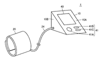
はじめに図1および図2を参照して、本実施の形態における電子血圧計(以下「血圧計」と略す)1の外観について説明する。
<Appearance and configuration>
(About appearance)
First, an external appearance of an electronic sphygmomanometer (hereinafter referred to as “blood pressure monitor”) 1 according to the present embodiment will be described with reference to FIGS. 1 and 2.
図1は、本発明の実施の形態における血圧計1の外観を示す図である。
図1を参照して、血圧計1は、本体部10と、被測定者のたとえば上腕に巻付けるためのカフ20と、本体部10とカフ20とを接続するためのエアチューブ24とを備える。
FIG. 1 is a diagram showing an appearance of a
Referring to FIG. 1,
図2は、本発明の実施の形態における本体部10を後方から見た斜視図である。
図1および図2を参照して、本体部10は、5面体であり、机などの台と接する設置面と、設置面と所定の角度をなす表面10Aと、設置面に対して垂直な面である2つの側面10B,10Cおよび背面10Dとを有している。
FIG. 2 is a perspective view of
Referring to FIGS. 1 and 2,
本体部10の表面10Aには、測定結果などを表示するための表示部40と、ユーザ(代表的に被測定者)からの指示の入力を受付けるための操作部41とが配置される。操作部41は、たとえば、電源のON/OFFを切替えるための電源スイッチ41A、測定開始の指示を入力するための測定スイッチ41B、および、過去の測定結果を読出して表示する指示を入力するためのメモリスイッチ41Cとを含む。操作部41は、さらに、使用するユーザの識別情報(ユーザID)を特定するために操作されるIDスイッチ(図示せず)を含んでもよい。
On the
表示部40は、たとえば液晶等のディスプレイにより構成される。
本体部10の左側面10Bには、上述のエアチューブ24が接続されている。
The
The
本体部10の背面10Dには、太陽電池(ソーラーパネル)50が配置される。これにより、血圧計1を室内の窓際など外光が差す場所に置くと、太陽電池50が太陽光を受光し、受光した光エネルギーを電気エネルギーに変換する。つまり、太陽電池50は、受光量に応じて、電気エネルギーを発生する。発生した電気エネルギーは、本体部10に内蔵された充電池(二次電池)51(図3参照)に出力される。
A solar cell (solar panel) 50 is disposed on the
本体部10の右側面10Cには、ACアダプタ55がさらに接続可能であってもよい。
なお、血圧計1の本体部10の形状はこのような例に限定されない。
An
In addition, the shape of the main-
(ハードウェア構成について)
図3は、本発明の実施の形態における血圧計1のハードウェア構成を示すブロック図である。
(About hardware configuration)
FIG. 3 is a block diagram showing a hardware configuration of
図3を参照して、血圧計1のカフ20は、空気が内包される空気袋21を含む。空気袋21は、エアチューブ24を介して、本体部10に内蔵されたエア系25と接続される。
Referring to FIG. 3,
エア系25は、空気袋21内の圧力(以下、「カフ圧」という)を検出するための圧力センサ32と、空気袋21に空気を供給するためのポンプ33と、空気袋21の空気を排出しまたは封入するために開閉される排気弁34とを含む。
The
本体部10は、各部を集中的に制御および監視するためのCPU(Central Processing Unit)100と、不揮発性のメモリ39と、表示部40と、操作部41と、電源部60と、時刻を計測するための計時部43と、アラーム音を発生するためのブザー44と、血圧計1の周辺の温度(以下「環境温度」という)を検出するための温度センサ45とを備える。また、本体部10は、エア系25に関連して、発振回路35と、ポンプ33を駆動するためのポンプ駆動回路36と、排気弁34を駆動するための弁駆動回路37とをさらに備える。
The
ポンプ駆動回路36は、CPU100から与えられる制御信号に基づいて、ポンプ33の駆動を制御する。弁駆動回路37は、CPU100から与えられる制御信号に基づいて、排気弁34の開閉制御を行なう。
The
圧力センサ32は、カフ圧により容量値が変化する。発振回路35は、圧力センサ32の容量値に応じた発振周波数の信号をCPU100に出力する。CPU100は、発振回路35から得られる信号を圧力に変換し圧力を検知する。
The capacitance value of the
メモリ39は、各種プログラムや各種データを記憶する。メモリ39は、血圧の測定結果を記憶するための測定結果記憶領域(図6参照)を含む。
The
電源部60は、太陽電池50が発電した電気エネルギーを蓄えるための充電池51と、着脱可能な乾電池(一次電池)52と、電源制御回路53とを含む。
The
電源制御回路53は、充電池51および乾電池52と電気的に接続され、両者が蓄えている電力を、選択的にポンプ駆動回路36や弁駆動回路37などの各種デバイスに供給する。電源制御回路53は、CPU100と電気的に接続され、CPU100との間で信号の送受信を行なう。電源制御回路53の構成例については後述する。
The power
充電池51は、たとえばニッケル水素電池である。乾電池52は、たとえばアルカリ電池である。
The
なお、本体部10は、ACアダプタ55を接続するためのコネクタ部54を含んでもよい。ACアダプタ55がコネクタ部54に接続されている場合、コネクタ部54を通って、ACアダプタ55からの電力が充電池51に供給される。なお、本実施の形態において、ACアダプタ55は、交流電流を直流電流に変換するための変換部(図示せず)を有しているものとする。
The
本実施の形態では、血圧計1は、充電池51および乾電池52の両方を備えるものとして説明するが、いずれか一方のみを備えてもよい。その場合、切替部58や切替制御部102の機能は不要である。
In the present embodiment,
また、血圧計1が充電池51を備えていない場合には、ACアダプタ55からの直流電流が電源制御回路53に直接供給されるようにしてもよい。
Further, when the
また、本実施の形態では、温度センサ45は含まれなくてもよい。
(機能構成について)
図4は、本発明の実施の形態における血圧計1の機能ブロック図である。
In the present embodiment, the
(About functional configuration)
FIG. 4 is a functional block diagram of the
図4を参照して、電源制御回路53は、充電池51の電圧を検出するための電圧検出部56と、乾電池52の電圧を検出するための電圧検出部57と、充電池51および乾電池52の出力を切替えるための切替部58とを含む。
Referring to FIG. 4, power
切替部58は、たとえばスイッチにより構成される。
なお、本実施の形態では、電圧検出部56,57は、電源部60の電源制御回路53内に含まれることとしたが、これらは、電源部60とは独立して設けられてもよい。
The switching
In the present embodiment,
CPU100は、その機能として、切替制御部102と、算出部104と、測定制御部106とを含む。
The
切替制御部102は、充電池51および乾電池52の切替制御を行なう。より具体的には、切替部58に制御信号を送信することで、切替部58に充電池51および乾電池52のいずれか一方を選択させる。
The switching
切替制御部102は、たとえば、ユーザからの指示に応じて、電池の切替制御を行なう。あるいは、電圧検出部56,57が検出する充電池51および乾電池52の電圧値に基づいて、切替制御を行なってもよい。たとえば、デフォルトまたはユーザからの指定により充電池51を優先する充電池優先モードが選択されていたとする。その場合、充電池51の電圧値がたとえば所定の閾値以下となった場合に、乾電池52に電源を切替えるよう制御してもよい。
For example, the switching
算出部104は、切替制御部102によって選択されている電池手段の現在の電圧値と、1回分の消費量とに基づいて、測定可能回数を算出する。算出された測定可能回数は、たとえば表示部40に表示される。
The
本実施の形態において、「1回分の消費量」とは、過去の1回の測定前後における電圧の消費量(=電圧の変化量(降下量))に基づく値である。「1回分の消費量」は、たとえば前回の測定における電圧消費量、すなわち、前回の測定における測定開始時の電圧値と測定終了時の電圧値との差を表わす。なお、前回の測定における電圧消費量に限定されず、過去の消費量の統計値(たとえば、平均値、最大値など)であってもよい。この場合、記憶されている全ての消費量データを用いてもよいし、一部の(たとえば、最新の所定回数分)消費量データのみを用いてもよい。 In the present embodiment, the “consumption amount for one time” is a value based on the consumption amount of voltage (= voltage change amount (drop amount)) before and after the past one measurement. “One-time consumption” represents, for example, the voltage consumption in the previous measurement, that is, the difference between the voltage value at the start of measurement and the voltage value at the end of measurement in the previous measurement. In addition, it is not limited to the voltage consumption in the last measurement, The statistical value (for example, average value, maximum value, etc.) of the past consumption may be sufficient. In this case, all stored consumption data may be used, or only a part (for example, the latest predetermined number of times) of consumption data may be used.
なお、血圧計1が、ユーザを特定して測定できる仕様である場合には、現在選択されているユーザについての過去の消費量を、測定可能回数の算出に用いることが望ましい。
When the
また、算出部104は、1回分の消費量に加え、さらに回復量を考慮して測定可能回数を算出してもよい。「回復量」とは、前回の測定終了時における電圧値と現在の電圧値との差を表わす。血圧測定の際、ポンプ33を駆動するため電池電圧は急激に降下する。その後、徐々に電圧値は回復するが、測定終了時においても電圧値の回復は完全には終わらず、測定終了後も電圧値の回復が継続される。そのため、前回の測定終了時からの電圧の変化量を回復量と表わしている。このような回復量をさらに考慮することで、一時的な電圧の降下の影響を除去することもできる。その結果、さらに精確な測定可能回数を算出することができる。
The
なお、前回の測定における電圧消費量と電圧の回復量とに基づいて測定可能回数を算出するのは、前回測定したユーザと同じユーザである場合に限定される。そのため、血圧計1が、ユーザを特定して測定できる仕様である場合には、前回測定したユーザと同じユーザであると判定された場合にのみ、電圧の回復量を考慮した算出が行なわれることとする。
Note that the number of measurable times is calculated based on the voltage consumption and the voltage recovery amount in the previous measurement only when the user is the same user as the previous measurement. Therefore, when the
具体的な測定可能回数の算出方法については、後述する。
測定制御部106は、ポンプ駆動回路36および弁駆動回路37を制御する。測定制御部106は、たとえばオシロメトリック法に従い、発振回路35からの信号(カフ圧信号)に基づいて、血圧値(たとえば最高血圧、最低血圧)を算出する。また、公知の手法に従い、脈拍数を算出する。算出された測定値は、後に詳述する消費量データと対応付けられてメモリ39に記憶される。
A specific method for calculating the number of measurable times will be described later.
The
なお、切替制御部102は、算出部104により算出された残りの測定可能回数に応じて、電池の切替制御を行なってもよい。たとえば、充電池51が選択されている場合、残りの測定可能回数が一定値(たとえば2回)以下となった場合に、電源を充電池51から乾電池52に切替えてもよい。
Note that the switching
なお、図4に示した各機能ブロックの動作は、メモリ39中に格納されたソフトウェアを実行することで実現されてもよいし、これらの機能ブロックのうち少なくとも1つについては、ハードウェアで実現されてもよい。
The operation of each functional block shown in FIG. 4 may be realized by executing software stored in the
<血圧計の動作の概要について>
本実施の形態における血圧計1の動作の概要について説明する。
<Outline of operation of blood pressure monitor>
An outline of the operation of the
図5は、本発明の実施の形態における電圧計1の動作を示すフローチャートである。図5のフローチャートに示す処理は、予めプログラムとしてメモリ39に格納されており、CPU100がこのプログラムを読み出して実行する。
FIG. 5 is a flowchart showing the operation of the
図5に示すフローチャートは、電源スイッチ41Aが押下された場合に開始されるものとする。また、説明の簡単のために、以下の説明においては、充電池51が電源として選択されているものと仮定する。
The flowchart shown in FIG. 5 is started when the
始めに、ユーザにより、測定を開始するユーザのユーザIDが選択される(ステップS2)。CPU100は、選択されたユーザIDを内部メモリに一時記録する。
First, the user ID of the user who starts measurement is selected by the user (step S2). The
ここで、選択されたユーザIDが、最新(前回)の測定日時の測定データに対応付けられたユーザIDと同じか否かがCPU100によって判断され、その結果が保持されるものとする。たとえば、最新の測定者と同じである場合にのみ、最新の測定者との同一性を示すための測定者フラグが“1”にセットされる。
Here, it is assumed that the
次に、測定可能回数表示処理が実行される(ステップS4)。測定可能回数表示処理については後に詳述する。 Next, a measurable number of times display process is executed (step S4). The measurable number display process will be described in detail later.
測定可能回数表示処理が継続されている際に、ユーザより測定開始の指示が入力されたとする。そうすると、算出部104は、電圧検出部56から得られる充電池51の現在の電圧値を、今回の測定開始時における電圧値Vsとして内部メモリに一時記録する(ステップS6)。
It is assumed that a measurement start instruction is input from the user when the measurable number of times display process is continued. Then, the
その後、測定制御部106による血圧測定処理が実行される。具体的には、測定制御部106は、まず、ポンプ33を駆動開始し、空気袋21の圧力を徐々に上昇(加圧)させる(ステップS8)。本例では、電源制御回路53の切替部58に充電池51が選択されているので、充電池51に蓄えられた電力がポンプ33の駆動源となる。
Thereafter, blood pressure measurement processing by the
カフ圧が血圧測定のための所定レベル(たとえば180mmHg)にまで達すると、測定制御部106はポンプ33を停止し、閉じていた排気弁34を徐々に開いて、空気袋21の空気を徐々に排気する。これにより、カフ圧は徐々に減圧される(ステップS10)。
When the cuff pressure reaches a predetermined level for blood pressure measurement (for example, 180 mmHg), the
なお、本実施の形態では、カフ圧が所定レベルになるまで加圧を継続することとした。しかしながら、加圧中に得られる脈波情報より最高血圧を推定し、推定された最高血圧+所定値(たとえば40mmHg)になるまで加圧を継続することとしてもよい。 In the present embodiment, pressurization is continued until the cuff pressure reaches a predetermined level. However, the systolic blood pressure may be estimated from the pulse wave information obtained during pressurization, and pressurization may be continued until the estimated systolic blood pressure + a predetermined value (for example, 40 mmHg).
測定制御部106は、公知の手法により血圧(最高血圧、最低血圧)および脈波数を算出する(ステップS12)。具体的には、カフ圧が徐々に減圧する過程において、測定制御部106は、発振回路35から得られる発振周波数に基づき脈波情報を抽出する。そして、抽出された脈波情報により血圧を算出する。
The
なお、本実施の形態では、減圧過程で得られる脈波情報に基づいて血圧を算出することとしたが、加圧過程で得られる脈波情報に基づいて血圧を算出してもよい。 In the present embodiment, the blood pressure is calculated based on the pulse wave information obtained in the decompression process, but the blood pressure may be calculated based on the pulse wave information obtained in the pressurization process.
次に、測定制御部106は、測定結果すなわち、ステップS12で算出された血圧値および脈拍数を表示部40に表示する(ステップS14)。
Next, the
続いて、算出部104は、電圧検出部56から得られる充電池51の現在の電圧値を、今回の測定終了時における電圧値Veとして内部メモリに一時記録する(ステップS16)。
Subsequently, the
最後に、測定制御部106は、測定結果をメモリ39内の測定結果記憶領域に格納する(ステップS18)。具体的には、一時記録していたユーザIDと対応付けて、測定値、電圧値Vs,Veを格納する。さらに、当該測定において選択されていた電池を特定するための電池IDを、電圧値Vs,Veと対応付けて格納することが好ましい。
Finally, the
以上で血圧計1の動作は終了(電源OFF)される。
本実施の形態においては、測定結果の表示が終わった時点を、「測定終了時(測定後)」であることとしたが、限定的ではない。たとえば、加圧(ステップS8)が終了した時点、減圧(ステップS10)が終了した時点、あるいは、血圧算出(ステップS12)が終了した時点であってもよい。
Thus, the operation of the
In the present embodiment, the time point when the display of the measurement result is ended is “at the end of measurement (after measurement)”, but is not limited. For example, it may be the time when pressurization (step S8) ends, the time when pressure reduction (step S10) ends, or the time when blood pressure calculation (step S12) ends.
<データ構造例について>
図6は、本発明の実施の形態における測定結果記憶領域390のデータ構造例を示す図である。
<About data structure example>
FIG. 6 is a diagram showing an example of the data structure of the measurement
図6を参照して、測定結果記憶領域390には、測定毎に、測定データMDj(j=1,2,…,n)がレコード単位で格納される。測定結果記憶領域390は、メモリ39内の予め定められた領域でってよい。
Referring to FIG. 6, measurement data MDj (j = 1, 2,..., N) is stored in the measurement
図7は、本発明の実施の形態における各測定データMDjのデータ構造例を示す図である。 FIG. 7 is a diagram showing a data structure example of each measurement data MDj in the embodiment of the present invention.
図7を参照して、各測定データMDjには、測定日時を示すデータと、ユーザIDを示すデータと、測定値すなわち、最高血圧(SBP)、最低血圧(DBP)および脈波数(PLS)を示すデータと、電池IDを示すデータと、測定開始時の電圧値Vsを示すデータと、測定終了時の電圧値Veを示すデータとが含まれる。測定日時は、たとえば測定スイッチ41Bが押下された時点の日時である。
Referring to FIG. 7, each measurement data MDj includes data indicating measurement date and time, data indicating a user ID, and measurement values, that is, maximum blood pressure (SBP), minimum blood pressure (DBP), and pulse wave number (PLS). Data indicating data, data indicating battery ID, data indicating voltage value Vs at the start of measurement, and data indicating voltage value Ve at the end of measurement are included. The measurement date and time is, for example, the date and time when the
なお、本実施の形態では、測定ごとの消費量データつまり、測定前後の電圧値Vs,Veも、測定データに含めることとしたが、限定的ではない。消費量データが、ユーザIDおよび測定日時と対応付けられて記憶されていれば、このような格納形態に限定されない。 In the present embodiment, the consumption data for each measurement, that is, the voltage values Vs and Ve before and after the measurement are also included in the measurement data, but this is not restrictive. As long as the consumption data is stored in association with the user ID and the measurement date and time, the storage form is not limited to such a storage form.
または、ユーザIDごとに記憶領域が設けられ、対応するユーザIDの記憶領域に、ユーザID以外のデータが格納されてもよい。 Alternatively, a storage area may be provided for each user ID, and data other than the user ID may be stored in the storage area of the corresponding user ID.
<測定可能回数表示処理について>
図5のステップS4における測定可能回数表示処理について、図8および図9を参照して詳細に説明する。なお、図5のステップS2において、測定者フラグが1にセットされている場合を想定して説明する。
<About measurable number of times display processing>
The measurable number display process in step S4 of FIG. 5 will be described in detail with reference to FIGS. Note that description will be made assuming that the measurer flag is set to 1 in step S2 of FIG.
図8は、本発明の実施の形態における測定可能回数表示処理を示すフローチャートである。図9は、本発明の実施の形態において測定可能回数の算出に用いられる電圧の検出タイミングを示すタイミングチャートである。 FIG. 8 is a flowchart showing the measurable number display process in the embodiment of the present invention. FIG. 9 is a timing chart showing the detection timing of the voltage used for calculating the measurable number of times in the embodiment of the present invention.
なお、図9には、特定のタイミングにおける電圧値のみを表わしており、実際の電圧の変化の軌跡を示すものではない。 Note that FIG. 9 shows only the voltage value at a specific timing, and does not show the locus of actual voltage change.
図8を参照して、算出部104は、測定結果記憶領域390から、選択されたユーザの前回の測定前後における電圧値Vs,Veを読出す(ステップS102)。具体的には、たとえば、まず、図5のステップS2で選択されたユーザID、および、現在選択中の電池の電池IDを含む測定データのうち、最新の測定日時の測定データを検索する。そして、検索された測定データに含まれる電圧値Vs,Veを読出す。
Referring to FIG. 8,
図9に示されるように、電圧値Vsは前回の測定開始時(t0)における電圧値を、電圧値Veは前回の測定終了時(t1)における電圧値を示している。 As shown in FIG. 9, the voltage value Vs indicates the voltage value at the start of the previous measurement (t0), and the voltage value Ve indicates the voltage value at the end of the previous measurement (t1).
次に、算出部104は、1回分の消費量として、前回測定の電圧消費量VAを算出する(ステップS104)。具体的には、測定終了時の電圧値Veから測定開始時の電圧値Vsを減算することにより、電圧消費量VAが算出される。
Next, the
次に、算出部104は、電圧検出部56から得られる充電池51の現在の電圧Vcrを検出する(ステップS106)。図9に示されるように、この時点での現在(時間t3)は、今回電源がONされてから(時間t2)、測定開始の指示が入力されるまでの間に位置している。
Next,
続いて、算出部104は、回復量VBを算出する(ステップS108)。回復量VBは、現在の電圧値Vcrから前回の測定終了時の電圧値Veを減算することにより算出される。
Subsequently, the
算出部104は、続いて、電圧降下量VCを算出する(ステップS110)。電圧降下量VCは、ステップS104で算出された電圧消費量VAとステップS108で算出された回復量VBとを加算することにより算出される。本実施の形態では、前回の電圧消費量を用いているため、電圧降下量VCは、前回の測定開始時の電圧値からの降下量を表わしている。
Subsequently, the
算出部104は、残りの測定可能回数Nを算出する(ステップS112)。測定可能回数Nは、現在の電圧値Vcrと、充電池51のバッテリロー閾値Vthとの差を、ステップS110で算出された電圧降下量VCで除算することにより算出される。
The
バッテリーロー閾値は、電池ごとにメモリ39に予め記憶されているものとする。算出部104は、選択中の電池に対応するバッテリーロー閾値をメモリ39から読出すことで、電池の種類に応じた閾値を用いて測定可能回数を算出する。
It is assumed that the battery low threshold is stored in advance in the
測定可能回数Nが算出されると、CPU100は、表示部40に測定可能回数を表示する(ステップS114)。これにより、ユーザは、現時点での測定可能回数を把握することができる。なお、CPU100は、測定可能回数Nが、特定回数(たとえば20回)よりも多い場合には、所定回数おきに報知してもよい。
When the measurable number N is calculated, the
次に、CPU100は、ユーザより、測定開始の指示が入力されたか否かを判断する(ステップS116)。測定開始の指示が入力されるまで(ステップS116においてNO)、ステップS106〜ステップS114の処理が繰返される。
Next, the
測定開始の指示が入力されると(ステップS116においてYES)、処理はメインルーチンに戻される。 When a measurement start instruction is input (YES in step S116), the process returns to the main routine.
なお、電源がONされた後であって測定が開始される前に、ユーザによりメモリスイッチ41Cが押下された場合には、別ルーチンの処理(測定データ表示処理)が並行して実行されてよい。測定データ表示処理は、公知の手法により実現されてよい。 If the user presses the memory switch 41C after the power is turned on and before the measurement is started, another routine process (measurement data display process) may be executed in parallel. . The measurement data display process may be realized by a known method.
このように、測定データ表示処理の実行中にも、測定可能回数表示処理が実行されることにより、過去の測定データを表示中にも、現在の電圧を監視し、測定可能回数が算出および報知される。そのため、ユーザは、常に最新の測定可能回数を知ることができる。 As described above, the measurement possible number display process is executed even during the measurement data display process, so that the current voltage is monitored and the measurement possible number is calculated and notified while the past measurement data is being displayed. Is done. Therefore, the user can always know the latest measurable number of times.
図8および図9では、上述のように、測定者フラグがセットされている場合の例を示したが、測定者フラグがセットされていない場合は、算出部104は、たとえば次のようにして測定可能回数を算出する。なお、算出部104は、たとえば、ステップS102の前または後に、測定者フラグが1か否かを判断するものとする。
FIGS. 8 and 9 show examples in which the measurer flag is set as described above. However, when the measurer flag is not set, the
測定者フラグの値が0の場合、算出部104は、ステップS108(VBの算出)およびステップS110(VA+VBの加算)の処理を行なわない。そのため、ステップS112の処理に代えて、算出部104は、残りの有効電圧値(現在の電圧値Vcr−閾値Vth)を前回測定での電圧消費量VAで除算することにより、測定可能回数Nを算出する。
When the value of the measurer flag is 0, the
または、測定者フラグの値が0の場合、算出部104は、ステップS110に代えて、前回測定での電圧消費量VAに予め定められた値を加算した値を、電圧降下量VC#として算出してもよい。この場合、ステップS112に代えて、算出部104は、残りの有効電圧値(現在の電圧値Vcr−閾値Vth)を、電圧降下量VC#で除算することにより、測定可能回数Nを算出すればよい。
Alternatively, when the value of the measurer flag is 0, the
<測定可能回数の表示例について>
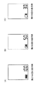
図10は、測定可能回数の表示例を示す図である。つまり、図10には、図8のステップS114において表示部40に表示される画面の一例が示されている。
<Example of display of measurable number of times>
FIG. 10 is a diagram illustrating a display example of the measurable number of times. That is, FIG. 10 shows an example of a screen displayed on the
図10(A)には、残りの測定可能回数がたとえば100回である場合の表示例が示されている。図10(B)には、残りの測定可能回数がたとえば50回である場合の表示例が示されている。図10(C)には、残りの測定可能回数がたとえば30回である場合の表示例が示されている。 FIG. 10A shows a display example when the remaining measurable number of times is 100, for example. FIG. 10B shows a display example when the remaining measurable number of times is, for example, 50 times. FIG. 10C shows a display example when the remaining measurable number of times is, for example, 30 times.
図10に示されるように、本実施の形態では、測定可能回数を数値で示すとともに、電池の残量を表わすアイコンが表示される。 As shown in FIG. 10, in the present embodiment, the number of measurable times is indicated by a numerical value, and an icon representing the remaining battery level is displayed.
なお、測定可能回数の情報の表示方法は、数値を表示するものに限定されず、たとえば、グラフ等によって表示されてもよい。 In addition, the display method of the information of the measurable frequency | count is not limited to what displays a numerical value, For example, you may display by a graph etc.
また、本実施の形態では、表示によって測定可能回数を報知した。しかしながら、表示に限定されず、たとえば、ブザー44が発する音の発振パターンや、モータ(ポンプ駆動回路36)の振動パターンなどによって報知してもよい。
In the present embodiment, the number of measurable times is notified by display. However, the present invention is not limited to the display, and notification may be made by, for example, an oscillation pattern of sound generated by the
<実施の形態の効果>
上述のように、本実施の形態によると、ユーザごとに、前回の測定開始時からの電圧の降下量を捉えることで、ユーザの電圧の消費傾向を捉えることができる。そして、残りの有効電圧値(現在の電圧からバッテリーロー閾値に達するまでの電圧値)に対するユーザの電圧の降下量の割合を算出することにより、測定可能回数を精確に算出することができる。
<Effect of Embodiment>
As described above, according to the present embodiment, for each user, the user's voltage consumption tendency can be grasped by grasping the amount of voltage drop from the start of the previous measurement. Then, by calculating the ratio of the amount of voltage drop of the user to the remaining effective voltage value (the voltage value from the current voltage until reaching the battery low threshold), the number of measurable times can be accurately calculated.
つまり、本実施の形態では、電池の放電特性に依存することなく測定可能回数が算出される。したがって、電池の個体差や電池の種類によらず、正確な測定可能回数を算出することができる。 That is, in the present embodiment, the measurable number of times is calculated without depending on the discharge characteristics of the battery. Therefore, it is possible to calculate the exact number of times that can be measured regardless of the individual difference between the batteries and the type of the battery.
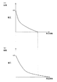
また、ユーザごとに、腕の太さが異なるため、ユーザごとにポンプの駆動時間は異なる。その結果、ユーザごとに1回の測定に要する電圧の消費量が異なる。その結果、同じ容量かつ同じ種類の電池を使用したとしても、測定回数は異なる。ポンプの駆動時間が測定回数に与える影響を図11を参照して説明する。 Moreover, since the thickness of an arm differs for every user, the drive time of a pump differs for every user. As a result, the voltage consumption required for one measurement differs for each user. As a result, the number of measurements is different even if batteries of the same capacity and type are used. The influence of the pump driving time on the number of measurements will be described with reference to FIG.
図11は、被測定者の腕の太さの違いによる、電圧値と測定回数との関係を示す電圧−回数特性の違いを示す図である。 FIG. 11 is a diagram illustrating a difference in voltage-number characteristics indicating a relationship between a voltage value and the number of measurements due to a difference in the arm thickness of the measurement subject.
図11(A)には、標準よりも太い腕のユーザの電圧−回数特性の典型例が示されている。図11(B)には、標準よりも腕の細いユーザの電圧−回数特性の典型例が示されている。 FIG. 11A shows a typical example of the voltage-frequency characteristics of the user with a thicker arm than the standard. FIG. 11B shows a typical example of the voltage-frequency characteristics of a user whose arm is narrower than the standard.
図11(A),(B)を参照して、同じ電圧V0の時点から測定を開始したとしても、腕が太いユーザの方がポンプ駆動時間が長いため、測定回数は少なくなる。 Referring to FIGS. 11A and 11B, even if the measurement is started from the same voltage V0, the pump driving time is longer for a user with a thick arm, so the number of measurements is reduced.
本実施の形態では、固定的な電圧の閾値を用いて測定可能回数を算出するものではなく、対応するユーザ(被測定者)についての1回分の消費量を用いるため、ユーザの腕の太さの違いによる回数の誤差をなくすことができる。 In the present embodiment, since the number of measurable times is not calculated using a fixed voltage threshold value, the consumption amount for one time for the corresponding user (measured person) is used. The error of the number of times due to the difference of can be eliminated.
また、最高血圧+所定値まで加圧する場合にも、最高血圧の違いによりポンプ駆動時間は異なる。この場合にも、ユーザの最高血圧の違いによる回数の誤差をなくすことができる。 Even when pressurizing to the maximum blood pressure + predetermined value, the pump driving time varies depending on the difference in the maximum blood pressure. Also in this case, the error in the number of times due to the difference in the user's systolic blood pressure can be eliminated.
つまり、本実施の形態によると、選択中の電池の電圧が同じ値であっても、選択されたユーザに応じた最適な測定可能回数を報知することができる(つまり、測定可能回数がユーザにより異なりえる)。 That is, according to the present embodiment, even if the voltage of the selected battery is the same value, the optimum measurable number of times according to the selected user can be notified (that is, the measurable number of times is determined by the user). Different).
なお、ユーザを規定しない場合(ユーザIDを使用しない場合)であっても、家庭用の血圧計であれば同一のユーザが測定する場合がほとんどである。したがって、この場合にも、過去の1回分の消費量を使用することで、的確な測定可能回数を報知することができる。 Even when the user is not defined (when the user ID is not used), the same user often measures the blood pressure monitor for home use. Therefore, also in this case, it is possible to notify the accurate number of measurable times by using the past consumption.
また、本実施の形態によると、前回の測定終了時からの電圧の回復量も用いられる。そのため、非測定時、すなわち、モードの設定や過去の測定データの表示だけをする場合であっても、電圧値を定期的に監視し、測定可能回数の算出および更新が行なわれる。LCDを表示している時間はユーザによって異なるが、このように電圧値の定期的な監視が行なわれることにより、常に、信頼性の高い値をユーザに提示することができる。また、その結果、ユーザビリティを向上させることができる。 Further, according to the present embodiment, the amount of voltage recovery from the end of the previous measurement is also used. Therefore, even when not measuring, that is, when only setting the mode or displaying past measurement data, the voltage value is regularly monitored, and the number of measurable times is calculated and updated. Although the time during which the LCD is displayed varies depending on the user, a highly reliable value can always be presented to the user by regularly monitoring the voltage value in this way. As a result, usability can be improved.
また、環境温度によって電池の消費する割合は異なる。つまり、環境温度によって電池の放電特性が異なる。本実施の形態では、実際の電圧の降下量を検出することによって、測定可能回数を算出するため、環境温度の違いによる回数のずれを低減することができる。 Further, the battery consumption rate varies depending on the environmental temperature. That is, the discharge characteristics of the battery vary depending on the environmental temperature. In this embodiment, since the number of measurable times is calculated by detecting the actual voltage drop amount, the deviation in the number of times due to the difference in environmental temperature can be reduced.
上述のように、本実施の形態によると、ユーザは、精確な残りの測定可能回数を把握することができる。その結果、測定途中で電力不足になることがなくなる。 As described above, according to the present embodiment, the user can grasp the accurate remaining measurable number of times. As a result, there will be no power shortage during measurement.
また、ユーザは、測定可能回数に応じて新しい乾電池52を用意したり、充電池51を充電したりする準備を事前にすることができる。
In addition, the user can prepare in advance a new
また、充電池51の場合、ユーザは残量を十分に使い切ってから充電することができるので、充電池51の性能を十分に活かすことができる。つまり、充電池51の寿命を延ばすことができる。
Further, in the case of the
また、乾電池52の場合にも、ユーザは残量を十分に使い切ってから新しい電池に交換することができる。そのため、消費する電池量が減り、環境に良い。
In the case of the
<変形例1>
上記実施の形態では、測定ごとの電圧消費量を示す消費量データとして、測定前後の電圧値Vs,Veが測定データに格納されることとしたが、限定的ではない。たとえば、消費量データとして、測定前後の電圧消費量VA、および、測定終了時の電圧値Veが格納されてもよい。または、回復量を用いた算出を行なわないような場合には、測定前後の電圧消費量VAのみが、消費量データとして格納されてもよい。
<
In the above embodiment, the voltage values Vs and Ve before and after the measurement are stored in the measurement data as the consumption data indicating the voltage consumption for each measurement. However, the present invention is not limited to this. For example, voltage consumption VA before and after measurement and voltage value Ve at the end of measurement may be stored as consumption data. Or, when the calculation using the recovery amount is not performed, only the voltage consumption VA before and after the measurement may be stored as consumption data.
また、図8に示したような測定可能回数表示処理を行なう場合、測定者フラグの値が1の場合(前回と同様の測定者である場合)の電圧降下量VCは、“前回の測定開始時の電圧値Vs−現在の電圧値Vcr”とも表わすことができる。そのため、ユーザIDによるユーザの特定を行なわず、同一ユーザによる使用が想定される家庭用の血圧計の場合であり、かつ、前回測定での電圧消費量を用いる場合には、消費量データとして、測定開始時の電圧値Vsのみが格納されてもよい。 When the measurable number of times display processing as shown in FIG. 8 is performed, when the value of the measurer flag is 1 (when the measurer is the same as the previous measurer), the voltage drop VC is “the start of the previous measurement”. It can also be expressed as voltage value Vs of time−current voltage value Vcr ″. Therefore, in the case of a home sphygmomanometer that is assumed to be used by the same user without specifying the user by the user ID, and when using the voltage consumption in the previous measurement, as consumption data, Only the voltage value Vs at the start of measurement may be stored.
また、このような場合、測定可能回数表示処理として、次のような処理が行なわれてよい。図8のステップS102において、選択されたユーザの前回の電圧値Vsのみが読み出される。そして、ステップS104およびS108の処理は削除され、ステップS110において、現在の電圧値Vcrから前回の測定開始時の電圧値Vsが減算された値が、前回の測定開始時からの電圧降下量VCとして導出される。 In such a case, the following process may be performed as the measurable number of times display process. In step S102 of FIG. 8, only the previous voltage value Vs of the selected user is read out. Then, the processing of steps S104 and S108 is deleted, and in step S110, the value obtained by subtracting the voltage value Vs at the start of the previous measurement from the current voltage value Vcr is the voltage drop VC from the start of the previous measurement. Derived.
または、本実施の形態では、回復量は、現在の電圧値Vcrから前回の測定終了時の電圧値Veを減算した値として導出された。しかしながら、特に、測定者フラグの値が0の場合(今回の測定者が直近の測定者と同一ではない場合)には、過去の消費量データを用いて算出されてもよい。つまり、一度、連続して同一のユーザが測定した場合、消費量データとして、上述の測定前後の電圧値Vs,Veに加え、最終的にステップS108で算出された回復量VBの値(すなわち、前回の測定終了時から今回の測定開始時点の電圧の回復量)がさらに格納されてもよい。 Alternatively, in the present embodiment, the recovery amount is derived as a value obtained by subtracting the voltage value Ve at the end of the previous measurement from the current voltage value Vcr. However, in particular, when the value of the measurer flag is 0 (when the current measurer is not the same as the latest measurer), it may be calculated using past consumption data. That is, once the same user measures continuously, in addition to the voltage values Vs and Ve before and after the measurement described above as consumption data, the value of the recovery amount VB finally calculated in step S108 (ie, A voltage recovery amount from the end of the previous measurement to the current measurement start time) may be further stored.
そして、測定者フラグの値が0の場合には、図8のステップS108の処理の代わりに、過去の回復量を読み出してもよい。そして、読み出された過去の回復量を用いて、今回の測定開始時における電圧降下量VC#を推定してもよい。なお、電圧降下量VC#の算出に用いられる回復量は、直近のものであってもよいし、対象のユーザの全てのものまたは一部のものであってもよい。 If the value of the measurer flag is 0, the past recovery amount may be read instead of the process of step S108 in FIG. Then, the voltage drop amount VC # at the start of the current measurement may be estimated using the read past recovery amount. Note that the recovery amount used for the calculation of the voltage drop amount VC # may be the most recent amount, or all or a part of the target user.
<変形例2>
上述の実施の形態では、バッテリロー閾値Vthは、固定的な値であった。しかしながら、環境温度またはユーザの身体的条件に基づいて、バッテリーロー閾値を変えてもよい。
<
In the above-described embodiment, the battery low threshold value Vth is a fixed value. However, the battery low threshold may be varied based on environmental temperature or user physical conditions.
本実施の形態の変形例では、たとえば、温度センサ45が検出する環境温度に基づいて、バッテリロー閾値Vthを設定する。
In the modification of the present embodiment, for example, the battery low threshold Vth is set based on the environmental temperature detected by the
図12は、環境温度の違いによる充電池51の放電特性を示す図である。
図12を参照して、環境温度が標準的な温度である場合の充電池51の放電特性が曲線63で示されている。
FIG. 12 is a diagram showing the discharge characteristics of the
Referring to FIG. 12, the discharge characteristic of
環境温度が高いと、放電特性は、曲線63Aで示されるように、標準的な曲線63よりも上方にずれ、測定実施回数は増える。つまり、相対的に、1回分の電圧の変化量は、標準よりも小さい。したがって、環境温度が標準よりも高い部屋に血圧計1が設置されていた場合には、バッテリロー閾値は、標準の場合の閾値よりも低い値を設定する。
When the environmental temperature is high, the discharge characteristic shifts upward from the
これに対し、環境温度が低い場合には、放電特性は、曲線63Bで示されるように、標準的な曲線63よりも下方にずれ、測定実施回数は減る。つまり、相対的に、1回分の電圧の変化量は、標準よりも大きい。したがって、環境温度が標準よりも低い部屋に血圧計1が設置されていた場合には、バッテリロー閾値は、標準の場合の閾値よりも高い値を設定する。
On the other hand, when the environmental temperature is low, the discharge characteristic shifts downward from the
本変形例では、メモリ39には、たとえば、電池ごとに、環境温度とバッテリーロー閾値とを予め対応付けたデータテーブルが記憶されている。
In the present modification, the
算出部104は、図8のステップS112において、測定可能回数を算出する際に、本変形例では、次のような処理をさらに行なう。すなわち、算出部104は、温度センサ45から環境温度を検知する。そして、メモリ39に記憶された上記データテーブルを参照して、検知した環境温度に対応するバッテリーロー閾値を検索する。このようにして検索されたバッテリーロー閾値を、ステップS112における閾値Vthに代入し、測定可能回数を算出する。
When calculating the measurable number of times in step S112 of FIG. 8, the
このように、環境温度の違いにより、バッテリーロー閾値を変えることで、十分に回数のずれを低減することができる。 As described above, the difference in the number of times can be sufficiently reduced by changing the battery low threshold according to the difference in environmental temperature.
なお、他の例として、ユーザの腕の太さや最高血圧の違いによって、バッテリーロー閾値を変えてもよい。ユーザの腕の太さや最高血圧の違いによって、1回の測定で消費される電圧が異なる。血圧計1がユーザを規定しない仕様である場合には、複数のユーザによって血圧計1が使用されることも想定されるため、精確な測定可能回数を算出するために、バッテリーロー閾値を変えてもよい。
As another example, the battery low threshold may be changed depending on the thickness of the user's arm or the maximum blood pressure. The voltage consumed in one measurement varies depending on the thickness of the user's arm and the maximum blood pressure. When the
この場合、メモリ39には、たとえば、電池ごとに、腕の太さとバッテリーロー閾値とを予め対応付けたデータテーブルが記憶されている。また/または、メモリ39には、たとえば、電池ごとに、最高血圧値とバッテリーロー閾値とを予め対応付けたデータテーブルが記憶されている。
In this case, the
ユーザの腕の太さおよび/または最高血圧の情報は、電源ON時に、ユーザにより入力されてよい。 Information on the thickness of the user's arm and / or systolic blood pressure may be input by the user when the power is turned on.
腕の太さの情報の入力は、たとえば、次のようにして行なわれてよい。電源がONされると、CPU100は、表示部40に、「太腕」、「標準」、「細腕」それぞれを示すボタンを表示する。ユーザが操作部41を操作することにより、いずれか1つが選択される。CPU100は、ユーザにより選択された1つを、対象のユーザの腕の太さの情報として一時記録する。
The input of the arm thickness information may be performed as follows, for example. When the power is turned on, the
腕の太さの情報が入力されると、算出部104は、メモリ39に記憶された上記データテーブルを参照して、入力された腕の太さに対応するバッテリーロー閾値を検索する。このようにして検索されたバッテリーロー閾値を、ステップS112における閾値Vthに代入し、測定可能回数を算出する。
When the arm thickness information is input, the
最高血圧の情報の入力は、たとえば、次のようにして行なわれてよい。電源がONされると、CPU100は、表示部40に、最高血圧の入力領域を表示する。ユーザが操作部41を操作することにより、自身の最高血圧を入力する。CPU100は、ユーザにより入力された1つを、対象のユーザの最高血圧の情報として一時記録する。
The input of the systolic blood pressure information may be performed as follows, for example. When the power is turned on, the
最高血圧の情報が入力されると、算出部104は、環境温度や腕の太さの場合と同様の処理を行なう。
When the information on the maximum blood pressure is input, the
このように、腕の太さや最高血圧の違いにより、バッテリーロー閾値を変えることで、ユーザを規定しない場合でも、従来よりも精確に測定可能回数を算出することができる。 As described above, by changing the battery low threshold depending on the difference in arm thickness and systolic blood pressure, the number of measurable times can be calculated more accurately than in the past even when the user is not specified.
なお、血圧計1が、ユーザを規定しない(ユーザIDによりユーザを特定しない)仕様である場合には、血圧計1を使用するユーザが1人であるか複数人であるかをユーザに選択させてもよい。そして、複数人であることが選択された場合にのみ、上述のように、腕の太さや最高血圧の違いによって、バッテリーロー閾値を変更するモードで動作させるようにしてもよい。
When the
上述の実施の形態およびその変形例1,2では、自動的に加圧および減圧するための自動加圧機構(たとえば、ポンプ33、排気弁34など)を備えた血圧計を例に説明したが、手動で加圧および減圧するための自動加圧機構(たとえば、ゴム球)を備えた血圧計であってもよい。手動加圧機構を備えている場合には、図3に示したポンプ33、排気弁34、ポンプ駆動回路36および弁駆動回路37が不要である。その代わり、血圧計は、チューブ24を介して空気袋21と接続されるゴム球(不図示)を備えていればよい。
In the above-described embodiment and the first and second modifications thereof, the sphygmomanometer including an automatic pressurization mechanism (for example, the
今回開示された実施の形態はすべての点で例示であって制限的なものではないと考えられるべきである。本発明の範囲は上記した説明ではなくて特許請求の範囲によって示され、特許請求の範囲と均等の意味および範囲内でのすべての変更が含まれることが意図される。 The embodiment disclosed this time should be considered as illustrative in all points and not restrictive. The scope of the present invention is defined by the terms of the claims, rather than the description above, and is intended to include any modifications within the scope and meaning equivalent to the terms of the claims.
1 電子血圧計、10 本体部、20 カフ、21 空気袋、24 エアチューブ、25 エア系、32 圧力センサ、33 ポンプ、34 排気弁、35 発振回路、36 ポンプ駆動回路、37 弁駆動回路、39 メモリ、40 表示部、41 操作部、41A 電源スイッチ、41B 測定スイッチ、41C メモリスイッチ、43 計時部、44 ブザー、45 温度センサ、50 太陽電池、51 充電池、52 乾電池、53 電源制御回路、54 コネクタ部、55 ACアダプタ、56,57 電圧検出部、58 切替部、60 電源部、100 CPU、102 切替制御部、104 算出部、106 測定制御部、390 測定結果記憶領域。 1 Electronic Blood Pressure Monitor, 10 Main Body, 20 Cuff, 21 Air Bag, 24 Air Tube, 25 Air System, 32 Pressure Sensor, 33 Pump, 34 Exhaust Valve, 35 Oscillation Circuit, 36 Pump Drive Circuit, 37 Valve Drive Circuit, 39 Memory, 40 Display section, 41 Operation section, 41A Power switch, 41B Measurement switch, 41C Memory switch, 43 Timekeeping section, 44 Buzzer, 45 Temperature sensor, 50 Solar battery, 51 Rechargeable battery, 52 Dry battery, 53 Power control circuit, 54 Connector section, 55 AC adapter, 56, 57 Voltage detection section, 58 switching section, 60 power supply section, 100 CPU, 102 switching control section, 104 calculation section, 106 measurement control section, 390 measurement result storage area.
Claims (8)
被測定者の所定の身体部位に巻き付けるためのカフと、
前記カフ内の圧力を検知するための圧力検知手段と、
前記圧力検知手段からの信号に基づいて、前記被測定者の血圧を測定するための制御を行なうための測定制御手段と、
電池手段と、
前記電池手段の電圧を検出するための電圧検出手段と、
前記測定制御手段による測定前後における電圧の消費量に関する消費量データを記憶するための記憶手段と、
前記電池手段の現在の電圧値と、1回分の消費量とに基づいて、測定可能回数を算出するための算出手段と、
算出された前記測定可能回数を報知するための報知手段とを備え、
前記1回分の消費量は、対応する被測定者についての前記消費量データに基づく値であって、且つ前回分の消費量と、過去の消費量の統計値とのうちのいずれかであることが予め定められ、
前記記憶手段は、前記消費量データを、被測定者を特定するための識別情報と対応付けて記憶する、電子血圧計。 An electronic sphygmomanometer for measuring a subject's blood pressure,
A cuff for wrapping around a predetermined body part of the subject,
Pressure detecting means for detecting the pressure in the cuff;
Measurement control means for performing control for measuring the blood pressure of the measurement subject based on a signal from the pressure detection means;
Battery means;
Voltage detecting means for detecting the voltage of the battery means;
Storage means for storing consumption data relating to voltage consumption before and after measurement by the measurement control means;
A calculating means for calculating a measurable number of times based on a current voltage value of the battery means and a consumption for one time;
An informing means for informing the calculated measurable number of times ,
The one-time consumption is a value based on the consumption data for the corresponding person to be measured, and is either a previous consumption or a statistical value of past consumption. Is predetermined,
Said storage means, said consumption data, you stored in association with identification information for identifying a person to be measured, the electronic sphygmomanometer.
前記算出手段は、さらに、前回の前記第2の電圧データが示す電圧値と前記現在の電圧値との差を表わす回復量に基づいて、前記測定可能回数を算出する、請求項1に記載の電子血圧計。 The consumption data includes first voltage data before the start of measurement and second voltage data after the measurement,
The calculating means further based on the recovery amount representing the difference between the voltage value indicated by the last of said second voltage data and the current voltage value, calculates the measurement allowable number of times, according to claim 1 Electronic blood pressure monitor.
前記下限電圧値は、前記温度検出手段により検出された温度に応じて設定される、請求項3に記載の電子血圧計。 A temperature detecting means for detecting the temperature;
The electronic sphygmomanometer according to claim 3 , wherein the lower limit voltage value is set according to a temperature detected by the temperature detection means.
Priority Applications (1)
| Application Number | Priority Date | Filing Date | Title |
|---|---|---|---|
| JP2008331054A JP5353232B2 (en) | 2008-12-25 | 2008-12-25 | Electronic blood pressure monitor |
Applications Claiming Priority (1)
| Application Number | Priority Date | Filing Date | Title |
|---|---|---|---|
| JP2008331054A JP5353232B2 (en) | 2008-12-25 | 2008-12-25 | Electronic blood pressure monitor |
Publications (2)
| Publication Number | Publication Date |
|---|---|
| JP2010148712A JP2010148712A (en) | 2010-07-08 |
| JP5353232B2 true JP5353232B2 (en) | 2013-11-27 |
Family
ID=42568482
Family Applications (1)
| Application Number | Title | Priority Date | Filing Date |
|---|---|---|---|
| JP2008331054A Active JP5353232B2 (en) | 2008-12-25 | 2008-12-25 | Electronic blood pressure monitor |
Country Status (1)
| Country | Link |
|---|---|
| JP (1) | JP5353232B2 (en) |
Families Citing this family (2)
| Publication number | Priority date | Publication date | Assignee | Title |
|---|---|---|---|---|
| JP6926399B2 (en) | 2016-04-05 | 2021-08-25 | オムロンヘルスケア株式会社 | Diagnostic support device, diagnostic support method, and diagnostic support program |
| JP7045832B2 (en) * | 2017-10-31 | 2022-04-01 | フクダ電子株式会社 | Biometric information measuring device |
Family Cites Families (11)
| Publication number | Priority date | Publication date | Assignee | Title |
|---|---|---|---|---|
| JPH0375035A (en) * | 1989-08-17 | 1991-03-29 | Terumo Corp | Electronic blood pressure gauge |
| JPH0462488A (en) * | 1990-06-29 | 1992-02-27 | Matsushita Electric Works Ltd | Rest capacity display device for storage battery |
| JPH07146345A (en) * | 1993-11-25 | 1995-06-06 | Canon Inc | Charged amount display device for secondary battery |
| JPH0817477A (en) * | 1994-06-28 | 1996-01-19 | Mitsuoka Denki Seisakusho:Kk | Secondary battery capacity estimating method, deterioration diagnostic method, and battery charging device |
| JPH11500900A (en) * | 1995-12-14 | 1999-01-19 | フィリップス エレクトロニクス ネムローゼ フェンノートシャップ | Apparatus having a rechargeable battery and means for calculating and displaying the number of remaining sessions of a use session |
| JP2001008372A (en) * | 1999-06-21 | 2001-01-12 | Japan Storage Battery Co Ltd | Electrical apparatus |
| JP2001245857A (en) * | 2000-03-02 | 2001-09-11 | Matsushita Electric Ind Co Ltd | Biological data measuring device |
| JP2002320336A (en) * | 2001-04-20 | 2002-10-31 | Toshitaka Takei | Battery driving apparatus for displaying battery residual time |
| JP2003156548A (en) * | 2001-11-21 | 2003-05-30 | Hitachi Koki Co Ltd | Display of remainder in battery |
| JP3701664B2 (en) * | 2004-08-11 | 2005-10-05 | 九州日立マクセル株式会社 | Electric razor |
| JP2007282031A (en) * | 2006-04-10 | 2007-10-25 | Canon Inc | Energy information management device, energy-related information management method, computer program for executing the method, and recording medium with computer program recorded thereon |
-
2008
- 2008-12-25 JP JP2008331054A patent/JP5353232B2/en active Active
Also Published As
| Publication number | Publication date |
|---|---|
| JP2010148712A (en) | 2010-07-08 |
Similar Documents
| Publication | Publication Date | Title |
|---|---|---|
| JP5228880B2 (en) | Electronic blood pressure monitor | |
| RU2311119C2 (en) | Arterial pressure electron monitor and arterial pressure measuring system | |
| JP5853587B2 (en) | Electronic blood pressure monitor | |
| JP2010057817A (en) | Electronic sphygmomanometer | |
| JP4134234B1 (en) | Electronic blood pressure monitor | |
| JP5353232B2 (en) | Electronic blood pressure monitor | |
| US10987002B2 (en) | Biological information measurement device, and biological information measurement device operating method | |
| JP2013132326A (en) | Bioimpedance measuring device and bioimpedance measurement method | |
| JP2009273611A (en) | Bioinformation detecting device | |
| US7072791B2 (en) | Pedometer for use with pregnant woman | |
| JP2001245857A (en) | Biological data measuring device | |
| CN201831887U (en) | Electronic sphygmomanometer | |
| JP5993013B2 (en) | Body moisture meter, body moisture meter control method, and storage medium | |
| CN105246546B (en) | automatic power management for external defibrillator | |
| JP2009225842A (en) | Electronic sphygmomanometer and charging guide method | |
| JP2009195599A (en) | Electronic sphygmomanometer | |
| JP2009219704A (en) | Electronic sphygmomanometer | |
| JP2009195598A (en) | Biological information measuring apparatus | |
| JP2013132325A (en) | Bioimpedance measuring device and bioimpedance measurement method | |
| KR200328014Y1 (en) | A blood pressure pulsation recorder | |
| JP2001174533A (en) | Battery remaining capacity calculating device and battery remaining capacity calculating method | |
| JPH10314143A (en) | Subcutaneous fat meter | |
| JP3009306B2 (en) | Electronic thermometer | |
| JPH10314144A (en) | Subcutaneous fat meter and its control method | |
| JPH10314145A (en) | Adipometer |
Legal Events
| Date | Code | Title | Description |
|---|---|---|---|
| A621 | Written request for application examination |
Free format text: JAPANESE INTERMEDIATE CODE: A621 Effective date: 20111128 |
|
| A977 | Report on retrieval |
Free format text: JAPANESE INTERMEDIATE CODE: A971007 Effective date: 20130531 |
|
| A131 | Notification of reasons for refusal |
Free format text: JAPANESE INTERMEDIATE CODE: A131 Effective date: 20130611 |
|
| A521 | Written amendment |
Free format text: JAPANESE INTERMEDIATE CODE: A523 Effective date: 20130709 |
|
| TRDD | Decision of grant or rejection written | ||
| A01 | Written decision to grant a patent or to grant a registration (utility model) |
Free format text: JAPANESE INTERMEDIATE CODE: A01 Effective date: 20130730 |
|
| A61 | First payment of annual fees (during grant procedure) |
Free format text: JAPANESE INTERMEDIATE CODE: A61 Effective date: 20130812 |
|
| R150 | Certificate of patent or registration of utility model |
Ref document number: 5353232 Country of ref document: JP Free format text: JAPANESE INTERMEDIATE CODE: R150 Free format text: JAPANESE INTERMEDIATE CODE: R150 |