JP5341815B2 - Mobile phone, power saving control program, and power saving control method - Google Patents
Mobile phone, power saving control program, and power saving control method Download PDFInfo
- Publication number
- JP5341815B2 JP5341815B2 JP2010099614A JP2010099614A JP5341815B2 JP 5341815 B2 JP5341815 B2 JP 5341815B2 JP 2010099614 A JP2010099614 A JP 2010099614A JP 2010099614 A JP2010099614 A JP 2010099614A JP 5341815 B2 JP5341815 B2 JP 5341815B2
- Authority
- JP
- Japan
- Prior art keywords
- power saving
- display
- time
- state
- setting
- Prior art date
- Legal status (The legal status is an assumption and is not a legal conclusion. Google has not performed a legal analysis and makes no representation as to the accuracy of the status listed.)
- Expired - Fee Related
Links
- 238000000034 method Methods 0.000 title claims description 67
- 230000007704 transition Effects 0.000 claims description 9
- 230000008569 process Effects 0.000 description 50
- 238000004891 communication Methods 0.000 description 20
- 230000006870 function Effects 0.000 description 17
- 230000005236 sound signal Effects 0.000 description 8
- 230000005540 biological transmission Effects 0.000 description 7
- 230000001413 cellular effect Effects 0.000 description 6
- 230000004397 blinking Effects 0.000 description 4
- 230000008859 change Effects 0.000 description 4
- 238000013500 data storage Methods 0.000 description 4
- 230000004044 response Effects 0.000 description 4
- 238000001514 detection method Methods 0.000 description 3
- 238000012790 confirmation Methods 0.000 description 2
- 230000001419 dependent effect Effects 0.000 description 2
- 230000005389 magnetism Effects 0.000 description 2
- 230000007246 mechanism Effects 0.000 description 2
- 230000007103 stamina Effects 0.000 description 2
- 125000002066 L-histidyl group Chemical group [H]N1C([H])=NC(C([H])([H])[C@](C(=O)[*])([H])N([H])[H])=C1[H] 0.000 description 1
- HBBGRARXTFLTSG-UHFFFAOYSA-N Lithium ion Chemical compound [Li+] HBBGRARXTFLTSG-UHFFFAOYSA-N 0.000 description 1
- FKNQFGJONOIPTF-UHFFFAOYSA-N Sodium cation Chemical compound [Na+] FKNQFGJONOIPTF-UHFFFAOYSA-N 0.000 description 1
- 229910052771 Terbium Inorganic materials 0.000 description 1
- ZRXYMHTYEQQBLN-UHFFFAOYSA-N [Br].[Zn] Chemical compound [Br].[Zn] ZRXYMHTYEQQBLN-UHFFFAOYSA-N 0.000 description 1
- 239000002253 acid Substances 0.000 description 1
- 238000010586 diagram Methods 0.000 description 1
- 239000000446 fuel Substances 0.000 description 1
- 238000009434 installation Methods 0.000 description 1
- 229910001416 lithium ion Inorganic materials 0.000 description 1
- 230000007774 longterm Effects 0.000 description 1
- 229910052751 metal Inorganic materials 0.000 description 1
- 239000002184 metal Substances 0.000 description 1
- 229910052987 metal hydride Inorganic materials 0.000 description 1
- 238000010295 mobile communication Methods 0.000 description 1
- 229910052759 nickel Inorganic materials 0.000 description 1
- PXHVJJICTQNCMI-UHFFFAOYSA-N nickel Substances [Ni] PXHVJJICTQNCMI-UHFFFAOYSA-N 0.000 description 1
- -1 nickel metal hydride Chemical class 0.000 description 1
- 229910001415 sodium ion Inorganic materials 0.000 description 1
- 239000000758 substrate Substances 0.000 description 1
- 229910052715 tantalum Inorganic materials 0.000 description 1
Images


Classifications
-
- Y—GENERAL TAGGING OF NEW TECHNOLOGICAL DEVELOPMENTS; GENERAL TAGGING OF CROSS-SECTIONAL TECHNOLOGIES SPANNING OVER SEVERAL SECTIONS OF THE IPC; TECHNICAL SUBJECTS COVERED BY FORMER USPC CROSS-REFERENCE ART COLLECTIONS [XRACs] AND DIGESTS
- Y02—TECHNOLOGIES OR APPLICATIONS FOR MITIGATION OR ADAPTATION AGAINST CLIMATE CHANGE
- Y02D—CLIMATE CHANGE MITIGATION TECHNOLOGIES IN INFORMATION AND COMMUNICATION TECHNOLOGIES [ICT], I.E. INFORMATION AND COMMUNICATION TECHNOLOGIES AIMING AT THE REDUCTION OF THEIR OWN ENERGY USE
- Y02D30/00—Reducing energy consumption in communication networks
- Y02D30/70—Reducing energy consumption in communication networks in wireless communication networks
Landscapes
- Telephone Function (AREA)
Description
この発明は、携帯電話機、省電力制御プログラムおよび省電力制御方法に関し、特に消費電力を抑える省電力モードが設定可能な、携帯電話機に関する。 The present invention relates to a mobile phone, a power saving control program, and a power saving control method, and more particularly to a mobile phone capable of setting a power saving mode for suppressing power consumption.
従来、特にたとえば消費電力を抑える省電力モードが設定可能な携帯電話機は広く知られており、この種の装置の一例が特許文献1に開示されている。この背景技術の携帯情報端末装置は、省電力モードにおける装置各部の各パラメータとして、キーLEDおよびLCDバックライトの点灯のオン/オフと持続時間、バイブレータのオン/オフおよびLCDパーシャルモードまでの時間などを記憶するメモリを備える。そして、携帯情報端末装置の筐体にはスタミナモード設定キーが設けられており、スタミナモード設定キーが操作されると、CPUはメモリに記憶された各パラメータの設定内容を読み出し、省電力モードを設定する。
ところが、背景技術の携帯情報端末装置の省電力モードでは、省電力モードの設定が優先されてしまい、ユーザが個別に設定したパラメータが優先されるようなことは無かった。 However, in the power saving mode of the portable information terminal device of the background art, the setting of the power saving mode is prioritized, and the parameters individually set by the user are not prioritized.
それゆえに、この発明の主たる目的は、新規な、携帯電話機、省電力制御プログラムおよび省電力制御方法を提供することである。 Therefore, a main object of the present invention is to provide a novel mobile phone, a power saving control program, and a power saving control method.
この発明の他の目的は、省電力モードであっても、使用者の設定を優先することができる、携帯電話機、省電力制御プログラムおよび省電力制御方法を提供することである。 Another object of the present invention is to provide a mobile phone, a power saving control program, and a power saving control method that can prioritize user settings even in the power saving mode.
この発明は、上記の課題を解決するために、以下の構成を採用した。なお、括弧内の参照符号および補足説明等は、この発明の理解を助けるために記述する実施形態との対応関係を示したものであって、この発明を何ら限定するものではない。 The present invention employs the following configuration in order to solve the above problems. The reference numerals in parentheses, supplementary explanations, and the like indicate the corresponding relationship with the embodiments described in order to help understanding of the present invention, and do not limit the present invention.
第1の発明は、消費電力を抑える省電力モードが設定でき、特定状態で特定時間が経過すると省電力状態に遷移する、携帯電話機であって、省電力モードにおいて、省電力状態に遷移させるための時間を第1設定時間として記憶する第1記憶部、任意に設定された時間を、省電力状態に遷移させるための第2設定時間として記憶する第2記憶部、省電力モードが設定され、さらに特定状態のとき、第2設定時間が第1設定時間よりも短いか否かを判断する判断部、および判断部によって第2設定時間が第1設定時間よりも短いと判断されたとき、第2設定時間を特定時間として設定する設定部を備える、携帯電話機である。 A first aspect of the present invention is a mobile phone that can set a power saving mode that suppresses power consumption, and that transitions to a power saving state when a specific time elapses in a specific state, in order to shift to a power saving state in the power saving mode A first storage unit that stores the time as the first set time, a second storage unit that stores the arbitrarily set time as the second set time for transitioning to the power saving state, and the power saving mode are set, Further, in the specific state, when the determination unit determines whether the second setting time is shorter than the first setting time and the determination unit determines that the second setting time is shorter than the first setting time, 2 is a mobile phone including a setting unit that sets a set time as a specific time.
第1の発明では、携帯電話機(10:実施例において対応する部分を例示する参照符号。以下、同じ。)は、使用者による操作に応じて、消費電力を抑える省電力モードが設定される。また、携帯電話機は、電力消費が大きい特定状態で特定時間が経過すると、消費電力を抑えるために省電力状態に遷移する。第1記憶部(38)は、たとえばRAMなどの記憶装置であり、電力モードにおいて省電力状態に遷移させるための時間として、第1設定時間(省電力設定値)を記憶する。また、第2記憶部(24,S11)は、たとえば使用者によって任意に設定された時間を、省電力状態に遷移させるための第2設定時間(ユーザ設定値)として記憶する。判断部(24,S23)は、たとえば、携帯電話機に省電力モードが設定され、特定状態に遷移すると、第2設定時間が第1設定時間よりも短いか否かを判断する。設定部(24,S27)は、第2設定時間が第1設定時間よりも短いと判断されると、第2設定時間を特定時間として設定する。 In the first invention, the cellular phone (10: reference numerals exemplifying corresponding parts in the embodiment; the same applies hereinafter) is set in a power saving mode for suppressing power consumption in accordance with an operation by a user. In addition, when a specific time elapses in a specific state where power consumption is large, the mobile phone transitions to a power saving state in order to suppress power consumption. The first storage unit (38) is a storage device such as a RAM, for example, and stores a first set time (power saving set value) as a time for shifting to the power saving state in the power mode. Moreover, a 2nd memory | storage part (24, S11) memorize | stores the time arbitrarily set, for example by the user as 2nd setting time (user setting value) for changing to a power saving state. For example, the determination unit (24, S23) determines whether or not the second set time is shorter than the first set time when the power saving mode is set in the mobile phone and the state is changed to the specific state. When it is determined that the second setting time is shorter than the first setting time, the setting unit (24, S27) sets the second setting time as the specific time.
第1の発明によれば、第1設定時間よりも短い第2設定時間が特定時間として設定されるため、第1設定時間が特定時間として設定される場合に比べて消費電力が抑えられる。そのため、省電力モードの設定よりも、使用者による設定の方が消費電力を抑えることができれば、使用者の設定を優先することができる。 According to the first aspect, since the second set time that is shorter than the first set time is set as the specific time, the power consumption can be suppressed compared to the case where the first set time is set as the specific time. Therefore, if the setting by the user can suppress power consumption rather than the setting of the power saving mode, the setting by the user can be prioritized.
第2の発明は、第1の発明に従属し、ディスプレイ、およびディスプレイを高輝度表示または低輝度表示に切り替える切換部をさらに備え、特定状態は、ディスプレイが高輝度表示に切り替えられた状態を含み、省電力状態では、ディスプレイが低輝度表示に切り替えられる。 A second invention is dependent on the first invention and further includes a display and a switching unit that switches the display to a high luminance display or a low luminance display, and the specific state includes a state in which the display is switched to a high luminance display. In the power saving state, the display is switched to the low luminance display.
第2の発明では、携帯電話機は、ディスプレイ(30)を備え、切換部(32)は、ディスプレイの高輝度表示、またはディスプレイの消費電力が高輝度表示よりも低い低輝度表示を切り替える。たとえば、ディスプレイが高輝度表示に切り替えられてから特定時間が経過すると、ディスプレイが低輝度表示に切り替えられる。 In the second invention, the mobile phone includes a display (30), and the switching unit (32) switches between high luminance display of the display or low luminance display whose power consumption of the display is lower than that of the high luminance display. For example, when a specific time elapses after the display is switched to the high luminance display, the display is switched to the low luminance display.
第2の発明によれば、消費電力が大きいディスプレイが、省電力状態では低輝度表示に切り替えられるため、効果的に消費電力を抑えることができる。 According to the second aspect of the invention, a display with high power consumption can be switched to low-brightness display in a power saving state, so that power consumption can be effectively suppressed.
第3の発明は、第2の発明に従属し、入力操作が行われる入力部(26)をさらに備え、特定状態は、ディスプレイが高輝度表示に切り替えられ、入力部に対して入力操作が行われない状態をさらに含む。 The third invention is dependent on the second invention and further includes an input unit (26) in which an input operation is performed. In the specific state, the display is switched to a high luminance display, and the input operation is performed on the input unit. It also includes a state that is not broken.
第3の発明では、入力部(26)は、キー入力装置とも呼ばれ、使用者によって入力操作が行われる。そして、特定状態には、ディスプレイが高輝度表示に切り替えられ、入力部に対して入力操作が行われない状態が含まれる。 In the third invention, the input unit (26) is also called a key input device, and an input operation is performed by the user. The specific state includes a state in which the display is switched to high luminance display and no input operation is performed on the input unit.
第3の発明によれば、消費電力が大きい状態で、携帯電話機が使用されないまま放置されると、省電力状態に遷移する。 According to the third aspect of the invention, when the mobile phone is left unused while the power consumption is large, the state transits to the power saving state.
第4の発明は、消費電力を抑える省電力モードが設定でき、特定状態で特定時間が経過すると省電力状態に遷移し、省電力モードにおいて、省電力状態に遷移させるための時間を第1設定時間として記憶する、携帯電話機(10)のプロセッサ(24)を、任意に設定された時間を、省電力状態に遷移させるための第2設定時間として記憶する記憶部(S11)、省電力モードが設定され、さらに特定状態のとき、第2設定時間が第1設定時間よりも短いか否かを判断する判断部(S23)、および判断部によって第2設定時間が第1設定時間よりも短いと判断されたとき、第2設定時間を特定時間として設定する設定部(S27)として機能させる、省電力制御プログラムである。 4th invention can set the power saving mode which suppresses power consumption, when specific time passes in a specific state, it changes to a power saving state, and in power saving mode, the time for changing to a power saving state is set to 1st A storage unit (S11) that stores the time set as the second set time for causing the processor (24) of the mobile phone (10) to store the arbitrarily set time to the power saving state, and stores the time as the time. When the second setting time is shorter than the first setting time by the determination unit (S23) that determines whether or not the second setting time is shorter than the first setting time when set and further in the specific state When it is determined, the power saving control program causes the second setting time to function as a setting unit (S27) that sets the specific time.
第4の発明でも、第1の発明と同様に、省電力モードの設定よりも、使用者による設定の方が消費電力を抑えることができれば、使用者の設定を優先することができる。 In the fourth invention, similarly to the first invention, if the setting by the user can suppress power consumption rather than the setting of the power saving mode, the setting of the user can be prioritized.
第5の発明は、消費電力を抑える省電力モードが設定でき、特定状態で特定時間が経過すると省電力状態に遷移し、省電力モードにおいて、省電力状態に遷移させるための時間を第1設定時間として記憶する、携帯電話機(10)の省電力制御方法であって、任意に設定された時間を、省電力状態に遷移させるための第2設定時間として記憶し(S11)、省電力モードが設定され、さらに特定状態のとき、第2設定時間が第1設定時間よりも短いか否かを判断し(S23)、そして第2設定時間が第1設定時間よりも短いと判断されたとき、第2設定時間を特定時間として設定する(S27)、省電力制御方法である。 According to a fifth aspect of the present invention, a power saving mode for suppressing power consumption can be set. When a specific time elapses in a specific state, the power saving mode is entered, and in the power saving mode, a time for making a transition to the power saving state is first set. A power saving control method for the mobile phone (10), which is stored as time, wherein an arbitrarily set time is stored as a second set time for transitioning to a power saving state (S11), and the power saving mode is When it is set and is in a specific state, it is determined whether or not the second setting time is shorter than the first setting time (S23), and when it is determined that the second setting time is shorter than the first setting time, This is a power saving control method in which the second set time is set as the specific time (S27).
第5の発明でも、第1の発明と同様に、省電力モードの設定よりも、使用者による設定の方が消費電力を抑えることができれば、使用者の設定を優先することができる。 In the fifth invention, similarly to the first invention, if the setting by the user can suppress the power consumption rather than the setting of the power saving mode, the setting of the user can be prioritized.
この発明によれば、省電力モードの設定よりも、使用者による設定の方が、消費電力を抑えることができれば、使用者の設定が優先される。 According to the present invention, setting by the user has priority over setting by the user if the power consumption can be suppressed rather than setting by the power saving mode.
この発明の上述の目的、その他の目的、特徴および利点は、図面を参照して行う以下の実施例の詳細な説明から一層明らかとなろう。 The above object, other objects, features, and advantages of the present invention will become more apparent from the following detailed description of embodiments with reference to the drawings.
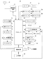
図1を参照して、この実施例の携帯電話機10は携帯端末の一種であり、CPUまたはコンピュータと呼ばれるプロセッサ24を含む。このプロセッサ24には、無線通信回路14、A/D16、第1D/A20a、第2D/A20b、キー入力装置26、表示ドライバ28、BL(Back Light:バックライト)制御回路32、フラッシュメモリ36、RAM38、LED制御回路40、磁気センサ44および電源回路48が接続される。また、無線通信回路14にはアンテナ12が接続され、A/D16にはマイク18が接続され、第1D/A20aおよび第2D/A20bにはアンプ(図示せず)を介して、第1スピーカ22aおよび第2スピーカ22bが接続される。また、表示ドライバ28にはディスプレイ30が接続され、BL制御回路32にはディスプレイ30の視認性を向上させるためのバックライト34が接続される。また、LED制御回路40には第1LED42aおよび第2LED42bが接続され、電源回路48には二次電池50が接続される。
Referring to FIG. 1, a mobile phone 10 of this embodiment is a kind of mobile terminal, and includes a
プロセッサ24は、携帯電話機10の全体制御を司る。第1記憶部であるRAM38は、プロセッサ24の作業領域(描画領域を含む)ないしバッファ領域として用いられる。フラッシュメモリ36には、携帯電話機10の文字、画像、音声、音および映像のようなコンテンツのデータなどが記録される。
The
A/D16は、当該A/D16に接続されたマイク18を通して入力される音声ないし音についてのアナログ音声信号を、デジタル音声信号に変換する。第1D/A20aおよび第2D/A20bは、デジタル音声信号をアナログ音声信号に変換(復号)して、アンプを介して第1スピーカ22aおよび第2スピーカ22bに与える。したがって、アナログ音声信号に対応する音声ないし音が第1スピーカ22aおよび第2スピーカ22bから出力される。
The A /
入力部であるキー入力装置26は、通話キーおよび終話キーなどを備えるとともに、「0」−「9」キー、「*」キーおよび「#」キーを含むダイヤルキーも備える。そして、使用者が操作したキーの情報(キーデータ)がプロセッサ24に入力される。
The
なお、キー入力装置26に含まれる各キーが操作されると、フィードバック処理が実行され、第2スピーカ22bからフィードバック音が出力される。そのため、使用者は、フィードバック音を聞くことで、キー入力操作に対する操作感を得ることができる。
When each key included in the
表示ドライバ28は、プロセッサ24の指示の下、当該表示ドライバ28に接続されたディスプレイ30の表示を制御する。なお、表示ドライバ28は表示する画像データを一時的に記憶するビデオメモリ(図示せず)を含む。
The
BL制御回路32は、プロセッサ24の指示の下、当該BL制御回路32に接続されたバックライト34の輝度を制御する。また、バックライト34は、ディスプレイ30に含まれる表示パネルに対してエッジライト方式に基づいて設置される。つまり、BL制御回路32は、バックライト34を制御することで、ディスプレイ30を高輝度表示または低輝度表示に切り替えることができる。そのため、BL制御回路32は切換部と呼ばれることもある。
The
ただし、ディスプレイ30の高輝度表示が維持されると、消費電力が高くなる。そのため、ディスプレイ30が高輝度表示に切り替えられ、キー入力装置26に対してキー入力操作されない状態(無操作状態)のまま特定時間が経過すると、ディスプレイ30が低輝度表示に切り替えられる。つまり、携帯電話機10は、ディスプレイ30を低輝度表示に切り替えることで、省電力状態に遷移することができる。なお、バックライト34の光源としては、LEDが採用されるが、冷陰極管などが採用されてもよい。また、本実施例の省電力状態には、ディスプレイ30およびバックライト34の電源がオフにされる状態も含まれる。
However, when the high-brightness display on the
LED制御回路40は、プロセッサ24の指示の下、当該LED制御回路32に接続された第1LED42aの輝度および第2LED42bの発光色を制御する。第1LED42aはキー入力装置26に含まれるキーの背面に取り付けられている。そのため、第1LED42aが発光すると、キーの視認性が向上する。また、第2LED42bは、携帯電話機10の状態を、発光色や点滅の間隔によって通知することができる。たとえば、本実施例では、第2LED42bの発光色や点滅によって、音声着信の状態を通知できる。
The
磁気センサ44は、磁石46が発する磁気を検知し、磁気の値をプロセッサ24に出力する。そして、プロセッサ24は、磁気センサ44が出力する磁気の値に応じて、携帯電話機10の開閉(図2参照)を検知する。
The
電源回路48は、二次電池50の電圧に基づく電源をシステム全体に供給する。ここで、電源回路48が電源をシステム全体に供給している場合には、電源オン状態と言うことにする。一方、電源回路48が電源をシステム全体に供給していない場合には、電源オフ状態と言うことにする。電源回路48は、電源オフ状態で、キー入力装置26によって電源オン操作がされると起動され、電源オフ状態で、キー入力装置26による電源オフ操作がされると停止される。さらに、電源オフ状態であっても、電源回路48は、二次電池50の充電を検出すると起動し、二次電池50の充電が完了するのに応答して停止する。また、二次電池50が充電されている状態を充電状態と言う。さらに、「充電」とは、端子Ta,Tbが外部電源と接続され外部電源から電力の供給を受け、二次電池50が電気エネルギーを蓄えることを言う。
The
なお、端子Taは+端子であり、端子Tbは−端子である。また、電源回路48は、二次電池50の電流値を測定することで、充電を検出する。さらに、プロセッサ24は、充電回路48から充電状態が通知されると、第2LED42bを、たとえば赤色に発光させる。
The terminal Ta is a + terminal and the terminal Tb is a-terminal. Further, the
無線通信回路14は、CDMA方式での無線通信を行うための回路である。たとえば、使用者がキー入力装置26を用いて音声発信を指示すると、無線通信回路14は、プロセッサ24の指示の下、音声発信処理を実行し、アンテナ12を介して音声発信信号を出力する。音声発信信号は、基地局および通信網(図示せず)を経て相手の電話機に送信される。そして、相手の電話機において着信処理が行われると、接続状態(通信可能状態)が確立され、プロセッサ24は通話処理を実行する。
The
通常の通話処理について具体的に説明すると、相手の電話機から送られてきた変調音声信号(高周波信号)はアンテナ12によって受信される。受信された変調音声信号には、無線通信回路14によって復調処理および復号処理が施される。そして、これらの処理によって得られた受話音声信号は、第1D/A20aによってアナログ音声信号に変換された後、第1スピーカ22aから出力される。一方、マイク18を通して取り込まれた送話音声信号は、A/D16によってデジタル音声信号に変換された後、プロセッサ24に与えられる。デジタル音声信号に変換された送話信号には、プロセッサ24の指示の下、無線通信回路14によって符号化処理および変調処理が施され、アンテナ12を介して出力される。したがって、変調音声信号は、基地局および通信網を介して相手の電話機に送信される。
The normal call processing will be specifically described. A modulated voice signal (high frequency signal) transmitted from the other party's telephone is received by the
また、相手の電話機からの発信信号がアンテナ12によって受信されると、無線通信回路14は、着呼(音声着信ともいう)をプロセッサ24に通知する。これに応じて、プロセッサ24は、表示ドライバ28を制御して、着信通知に記述された発信元情報(電話番号)をディスプレイ30に表示する。また、これとほぼ同時に、プロセッサ24は、第2スピーカ22bから着信音(着信メロディ、着信音声と言うこともある。)を出力させ、第2LED42bを、たとえば緑色で点滅させる。さらに、プロセッサ24は、図示しないモータを駆動(回転)させることで携帯電話機10を振動させる。
In addition, when a transmission signal from the other party's telephone is received by the
そして、使用者が、通話キーを用いて応答操作を行うと、無線通信回路14は、プロセッサ24の指示の下、音声着信処理を実行し、接続状態(通信可能状態)が確立され、プロセッサ24は上述した通常の通話処理を実行する。
When the user performs a response operation using the call key, the
そして、通話可能状態に移行した後に終話キーによって通話終了操作が行われると、プロセッサ24は、無線通信回路14を制御して、通話相手に通話終了信号を送信する。そして、通話終了信号の送信後、プロセッサ24は、通話処理を終了する。また、先に通話相手から通話終了信号を受信した場合も、プロセッサ24は、通話処理を終了する。さらに、通話相手によらず、移動通信網から通話終了信号を受信した場合も、プロセッサ24は通話処理を終了する。
Then, when a call end operation is performed with the call end key after shifting to the call ready state, the
また、携帯電話機10は、消費電力を抑えるための省電力モードを任意に設定できる、省電力機能を有する。たとえば、携帯電話機10に省電力モードが設定されると、省電力状態に遷移するための特定時間、第2スピーカ22bによるフィードバック処理、第1LED42aおよび第2LED42bの点灯および点滅のタイミングなどに関する設定がまとめて変更される。そして、使用者は、キー入力装置26に対する操作によって、省電力モードを容易に設定できる。
In addition, the mobile phone 10 has a power saving function that can arbitrarily set a power saving mode for suppressing power consumption. For example, when the power saving mode is set in the mobile phone 10, settings related to a specific time for transitioning to the power saving state, feedback processing by the second speaker 22b, timings of lighting and blinking of the
なお、携帯電話機10は、ネットワーク(図示せず)に接続されるサーバとのデータ通信を確立することで、メール機能およびブラウザ機能を実行することができる。さらに、RAM38に記憶されているアドレス帳データを管理するアドレス帳機能も実行することができる。
Note that the cellular phone 10 can execute a mail function and a browser function by establishing data communication with a server connected to a network (not shown). Furthermore, an address book function for managing address book data stored in the
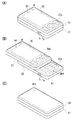
図2(A)は、スライド型の携帯電話機の閉状態の外観を示す外観図であり、図2(B)は、スライド型の携帯電話機の開状態の外観を示す外観図であり、図2(C)は、スライド型の携帯電話機の閉状態の外観の裏面を示す外観図である。図2(A)−(C)を参照して、携帯電話機10は、各々が平面矩形の第1筐体C1および第2筐体C2を有する。また、第1筐体C1および第2筐体C2の厚みは略同じである。 2A is an external view showing an external appearance of the slide type mobile phone in a closed state, and FIG. 2B is an external view showing an external appearance of the slide type mobile phone in an open state. (C) is an external view showing the back of the external appearance of the slide type mobile phone in the closed state. 2A to 2C, the mobile phone 10 includes a first casing C1 and a second casing C2 each having a planar rectangular shape. The thickness of the first casing C1 and the second casing C2 is substantially the same.
第1筐体C1は第2筐体C2の上に重ねられた状態で、図示しないスライド機構によって連結される。したがって、図2(B)に示すように、第1筐体C1は第2筐体C2の長さ方向にスライド可能である。また、端子Taおよび端子Tbのそれぞれは、第2筐体C2の側面に設けられる。なお、第1筐体C1および第2筐体C2にそれぞれ内蔵される基板は、フレキシブル・プリント配線基板によって電気的に接続されている。 The first casing C1 is connected to the second casing C2 by a slide mechanism (not shown) in a state of being overlaid on the second casing C2. Therefore, as shown in FIG. 2B, the first casing C1 can slide in the length direction of the second casing C2. In addition, each of the terminal Ta and the terminal Tb is provided on a side surface of the second casing C2. In addition, the board | substrate each incorporated in the 1st housing | casing C1 and the 2nd housing | casing C2 is electrically connected by the flexible printed wiring board.
図示しないマイク18は第2筐体C2に内蔵され、内蔵されたマイク18に通じる開口OP2は第2筐体C2の長さ方向一方の上面に設けられる。また、図示しない第1スピーカ22aは第1筐体C1に内蔵され、内蔵された第1スピーカ22aに通じる開口OP1は第1筐体C1の長さ方向一方の上面に設けられる。さらに、図示しない第2スピーカ22bは第2筐体C2に内蔵され、内蔵された第2スピーカ22bに通じる開口OP3は第2筐体の長さ方向他方の下面に設けられる。
A microphone 18 (not shown) is built in the second housing C2, and an opening OP2 leading to the built-in
キー入力装置26は、複数のキーを含む第1キー群26aと第2キー群26bとを含む。第1キー群26aは、方向キー、通話キー、終話キー、メニューおよび確定キーから構成されており、第1筐体C1の上面に設けられる。また、第2キー群26bは、テンキーなどから構成されており、第2筐体C2の上面に設けられる。また、ディスプレイ30は、モニタ画面が第1筐体C1の上面に露出するように取り付けられる。
The
たとえば、使用者は、ディスプレイ30を確認しながら、テンキーを操作して電話番号を入力し、通話キーによって発呼操作を行い、終話キーによって通話終了操作を行う。また、使用者は、メニューキーを操作することでメニュー画面を表示し、方向キーなどによって任意のメニューを選択することができる。さらに、使用者は、確定キーを操作することで、選択されたメニューを確定することができる。そして、使用者は、終話キーを長押しすることで携帯電話機10の電源をオン/オフする。
For example, the user operates the numeric keypad to input a telephone number while confirming the
また、第1筐体C1の長さ方向一方の上面には、第2LED42bに通じる窓Wが設けられ、この窓W1には、可視光を透過するプラスチックがはめ込まれている。これにより、使用者は、第1筐体C1の上面を視認することで、第2LED42bの発光色および点滅も確認できる。
In addition, a window W that communicates with the
磁気センサ44は第1筐体C1の長さ方向他方に内蔵され、磁石46は、図2(A)に示す閉状態で、磁気センサ44と最も近い状態となるように、第2筐体C2の長さ方向一方に内蔵される。そして、磁気センサ44は、図2(A)に示す状態では最大値を出力し、図2(B)に示す状態では最小値を出力する。つまり、プロセッサ24は、磁気センサ44が最大値を出力すると開状態を検出し、磁気センサ44が最小値を出力すると閉状態を検出する。
The
また、携帯電話機10は開閉の検出に応じてディスプレイ30の表示を変化させるオープン機能およびクローズ機能を有している。たとえば、携帯電話機10が閉状態から開状態にされると、オープン機能により、ディスプレイ30は高輝度表示に切り替えられる。また、携帯電話機10が開状態から閉状態にされ、さらに無操作状態が2秒間維持されると、クローズ機能によりディスプレイ30の表示は消去され、ディスプレイ30およびバックライト34の電源がオフにされる。
In addition, the mobile phone 10 has an open function and a close function that change the display of the
なお、本実施例における無操作状態には、充電の開始/終了による状態変化および音声着信が無い状態も含まれる。 The no-operation state in the present embodiment includes a state change due to the start / end of charging and a state where there is no incoming voice call.
また、磁気センサ44および磁石46は検出部と呼ばれることもある。また、検出部として、磁気センサ44および磁石46を用いた場合に限定されるものではなく、その他にも、たとえば、開閉の状態に応じて筐体の一方に設けられた押下部が、他方の筐体に設けられた筐体の被押下部を機械的に押下することにより、この押下状態による通電状態の変化などを検出して開閉を検出する機構であってもよい。
Moreover, the
さらに、アンテナ12、無線通信回路14、プロセッサ24、表示ドライバ28、BL制御回路32、バックライト34、フラッシュメモリ36、RAM38、LED制御回路40、第1LED42a、電源回路48および二次電池50は、第1筐体C1または第2筐体C2に内蔵されており、図2(A)−(C)では図示されない。
Further, the
図3(A),(B)は、ディスプレイ30、第2スピーカ22b、第2LED42bに対する設定を示す図解図である。図3(A)を参照して、通常モードにおける各種設定は、ユーザ設定テーブルに記憶され、ユーザ設定テーブルは「項目」と「詳細」との行から構成される。たとえば、「ディスプレイ(BL点灯)」に対応して、「30秒」が記録される。これは、ディスプレイ30の高輝度表示は、無操作状態で30秒間維持されることを示す。
3A and 3B are illustrative views showing settings for the
また、「ディスプレイ(微灯)」に対応して、「5秒」が記録される。これは、ディスプレイ30の低輝度表示(微灯状態)が無操作状態で5秒間維持されることを示す。なお、低輝度表示が無操作状態で5秒維持されると、ディスプレイ30およびバックライト34の電源がオフにされる。
Also, “5 seconds” is recorded corresponding to “display (light)”. This indicates that the low-intensity display (slight light state) of the
つまり、携帯電話機10は、ディスプレイ30が高輝度表示に切り替えられ、無操作状態のまま30秒経過すると、省電力状態に遷移する。また、省電力状態に遷移してから、無操作状態が5秒経過すると、ディスプレイ30の表示は消去され、さらに消費電力が少ない省電力状態となる。つまり、本実施例では、高輝度状態から低輝度状態に移行した際の当該低輝度状態(微灯状態)を省電力状態と定義するとともに、この省電力状態である低輝度状態(微灯状態)からディスプレイ30の表示が消去された状態も省電力状態と定義する。
That is, the mobile phone 10 transitions to the power saving state when the
また、「ランプ(通話中ランプ)」に対応して、「ON」が記録される。これは、通話中に第2LED42bが発光することを示す。また、「ランプ(お知らせランプ)」に対応して、「2秒間隔」が記録される。これは、携帯電話機10の状態を通知するための第2LED42bが、「2秒間隔」で点滅することを示す。なお、第2LED42bが点滅しないように設定されると、「2秒間隔」の代わりに「OFF」が記憶される。
In addition, “ON” is recorded in correspondence with “Lamp (calling lamp)”. This indicates that the
さらに、「キー操作音」に対応して、「ON」が記録される。これは、フィードバック音が第2スピーカ22bから出力されるように設定されていることを示す。そして、「クローズ」に対応して、「OFF」が表示される。これは、クローズ機能が「OFF」に設定されていることを示す。この場合、携帯電話機10が開状態から閉状態にされ、無操作状態が2秒維持されても、ディスプレイ30およびバックライト34の電源はオフにされない。
Furthermore, “ON” is recorded corresponding to “key operation sound”. This indicates that the feedback sound is set to be output from the second speaker 22b. Then, “OFF” is displayed in correspondence with “Close”. This indicates that the close function is set to “OFF”. In this case, even if the cellular phone 10 is changed from the open state to the closed state and the non-operation state is maintained for 2 seconds, the power of the
なお、ユーザ設定テーブルは、携帯電話機10が工場から出荷された状態では、初期値(デフォルト値)が設定されている。また、ユーザ設定テーブルの内容は、図示しない設定GUIによって任意に変更できる。ただし、他の実施例では、一部の設定は変更できないこともある。 In the user setting table, an initial value (default value) is set when the mobile phone 10 is shipped from the factory. Further, the contents of the user setting table can be arbitrarily changed by a setting GUI (not shown). However, in other embodiments, some settings may not be changed.
図3(B)を参照して、省電力モードにおける各種設定は、省電力テーブルに記憶され、その構成はユーザ設定テーブルと同じである。ただし、省電力テーブルでは、「ディスプレイ(BL点灯)」および「ディスプレイ(微灯)」に対応して、「10秒」および「5秒」が記録される。つまり、ディスプレイ30の高輝度表示は無操作状態で10秒維持され、低輝度表示は無操作状態で5秒維持される。つまり、省電力モードの携帯電話機10は、通常モードの携帯電話機10に比べて、20秒早く省電力状態に遷移する。そのため、省電力モードが設定された携帯電話機10の消費電力は、通常モードが設定された携帯電話機10に比べて低くなる。
Referring to FIG. 3B, various settings in the power saving mode are stored in the power saving table, and the configuration thereof is the same as that of the user setting table. However, in the power saving table, “10 seconds” and “5 seconds” are recorded in correspondence with “display (BL lighting)” and “display (light)”. That is, the high luminance display of the
また、「ランプ(通話中ランプ)」および「ランプ(お知らせランプ)」に対応して、「OFF」および「5秒間隔」が記憶される。つまり、第2LED42bは、通話中は電源がオフにされ、携帯電話機10の状態を通知する場合には「5秒間隔」で点滅する。
Further, “OFF” and “5-second interval” are stored in correspondence with “lamp (calling lamp)” and “lamp (notification lamp)”. That is, the
さらに、「キー操作音」に対応して「OFF」が記憶され、「クローズ」に対応して「ON」が記憶される。つまり、省電力モードが設定された携帯電話機10では、キー入力操作に対応するフィードバック音は出力されないように設定され、先のクローズ機能がオンにされる。 Furthermore, “OFF” is stored corresponding to “key operation sound”, and “ON” is stored corresponding to “close”. That is, in the mobile phone 10 in which the power saving mode is set, the feedback sound corresponding to the key input operation is set not to be output, and the previous close function is turned on.
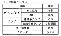
ここで、本実施例では、省電力モードの設定内容より、使用者によって任意に設定された内容の方が、消費電力を抑えることができる場合には、使用者の設定が優先される。たとえば、使用者が、設定GUIに対して、ディスプレイ30の高輝度表示を無操作状態で維持する時間として「5秒」を設定し、低輝度表示(微灯)を維持する時間として「0秒」を設定すると、ユーザ設定テーブルは図4のように更新される。
Here, in the present embodiment, when the content arbitrarily set by the user can suppress the power consumption, the user's setting is given priority over the content set in the power saving mode. For example, the user sets “5 seconds” as the time for maintaining the high-intensity display on the
図4を参照して、使用者によって設定されたユーザ設定テーブルでは、「ディスプレイ(BL点灯)」として「5秒」が記憶され、「ディスプレイ(微灯)」として「0秒」が記憶される。この場合、ディスプレイ30の高輝度表示が無操作状態のまま5秒経過すると、ディスプレイ30は高輝度表示から低輝度表示に切り替わり、直後にディスプレイ30およびバックライト34の電源がオフにされる。つまり、ディスプレイ30の高輝度表示が維持される時間に着目すれば、使用者によって設定された時間の方が短い。つまり、省電力モードの設定よりも、使用者の設定の方が消費電力を抑えることができる。
Referring to FIG. 4, in the user setting table set by the user, “5 seconds” is stored as “display (BL lighting)”, and “0 seconds” is stored as “display (light)”. . In this case, when 5 seconds elapses while the high luminance display of the
そのため、図4に示すユーザ設定テーブルがRAM38に記憶され、省電力モードが設定されていれば、ディスプレイ30の高輝度表示は、無操作状態で5秒間経過すると、低輝度表示に切り替わる。このように、本実施例では、省電力モードであっても、ユーザ設定値を特定時間として設定することができる。
Therefore, if the user setting table shown in FIG. 4 is stored in the
また、本実施例では、省電力状態では、消費電力が大きいディスプレイ30が低輝度表示に切り替えられるため、消費電力を効果的に抑えることができる。また、本実施例の携帯電話機10では、消費電力が大きい状態で、携帯電話機10が使用されないまま放置されると、省電力状態に遷移する。
Further, in this embodiment, in the power saving state, the
なお、省電力テーブルも任意に設定できる場合、使用者は、消費電力が抑えられるように設定するだけで、通常モードおよび省電力モードのどちらでも、自身の設定を反映させることができる。つまり、使用者は、省電力モードおよび通常モードを意識せずに設定することができるため、使用者の利便性が向上する。 When the power saving table can also be set arbitrarily, the user can reflect his / her setting in both the normal mode and the power saving mode only by setting so that the power consumption can be suppressed. That is, since the user can set without being conscious of the power saving mode and the normal mode, the convenience for the user is improved.
図5は、RAM38のメモリマップ300を示す図解図である。RAM38のメモリマップ300には、プログラム記憶領域302およびデータ記憶領域304が含まれる。また、プログラムおよびデータの一部は、フラッシュメモリ36から一度に全部または必要に応じて部分的かつ順次的に読み出され、RAM38に記憶されてからプロセッサ24によって処理される。
FIG. 5 is an illustrative view showing a memory map 300 of the
プログラム記憶領域302には、携帯電話機10を動作させるためのプログラムが記憶されている。たとえば、携帯電話機10を動作させるためのプログラムは、ユーザ設定プログラム310、高輝度表示制御プログラム312および低輝度表示制御プログラム314などから構成されている。
The
ユーザ設定プログラム310は、ユーザ設定テーブルの内容を任意に設定するためのプログラムである。高輝度表示制御プログラム312は、高輝度表示のディスプレイ30を制御するためのプログラムである。低輝度表示制御プログラム314は、低輝度表示のディスプレイ30を制御するためのプログラムである。
The
なお、図示は省略するが、携帯電話機10を動作させるためのプログラムには、省電力機能を制御するためのプログラム、文字入力を行うためのプログラム、二次電池50の充電を制御するためのプログラムおよび電源回路48を制御するためのプログラムなどが含まれる。
Although not shown, the program for operating the mobile phone 10 includes a program for controlling the power saving function, a program for inputting characters, and a program for controlling charging of the
続いて、データ記憶領域304には、閾値バッファ330が設けられるとともに、ユーザ設定テーブルデータ332、省電力テーブルデータ334が記憶される。さらに、データ記憶領域304には、省電力フラグ336、キー操作フラグ338、高輝度フラグ340、低輝度フラグ342、開閉フラグ344および充電フラグ346が設けられるとともに、高輝度カウンタ348も設けられる。
Subsequently, a
閾値バッファ330は、高輝度表示制御プログラム312おける、高輝度表示から低輝度表示に切り替える判断処理の閾値を一時的に記憶するバッファである。なお、閾値バッファ330に格納される閾値は、特定時間に対応する。ユーザ設定テーブルデータ332は、図3(A)または図4に示す構成のテーブルデータである。また、省電力テーブルデータ334は、図3(B)に示す構成のテーブルデータである。
The
省電力フラグ336は、省電力モードが設定されているか否かを判断するためのフラグである。たとえば、省電力フラグ336は1ビットのレジスタで構成される。たとえば、省電力フラグ336がオン(成立)にされると、レジスタにはデータ値「1」が設定される。一方、省電力フラグ336がオフ(不成立)にされると、レジスタにはデータ値「0」が設定される。そして、省電力フラグ336は、使用者が省電力モードを設定する操作を行うと、オンにされる。以下、他のフラグでも同じ構成であるため、フラグの構成の詳細な説明は省略する。
The
キー操作フラグ338は、キー入力装置26が出力するキーデータに基づいてオン/オフが切り替えられるフラグであり、キー入力操作が行われたか否かを判断するために利用される。また、高輝度フラグ340および低輝度フラグ342は、BL制御回路32を制御する命令に応じてオン/オフが切り替えられるフラグである。また、高輝度フラグ340はディスプレイ30が高輝度表示に切り替えられているか否かを判断するために利用され、ディスプレイ30が低輝度表示に切り替えられているか否かを判断するために利用される。
The
開閉フラグ344は、磁気センサ44が出力する値に基づいてオン/オフが切り替えられるフラグである。そのため、開閉フラグ344がオンであれば携帯電話機10が開状態であることを示し、オフであれば携帯電話機10が閉状態であることを示す。充電フラグ346は、電源回路48を制御する命令によってオン/オフが切り替えられるフラグであり、二次電池50が充電されているか否かを判断するために利用される。高輝度カウンタ348は、ディスプレイ30が高輝度表示であるときに、時間をカウントするためのカウンタである。たとえば、高輝度カウンタ348は無操作状態でカウントされ、キー入力操作、音声着信および二次電池50の充電開始/終了が検出されるとリセットされる。
The open /
なお、図示は省略するが、データ記憶領域304には、待受画像のデータなどが記憶されると共に、携帯電話機10の動作に必要なカウンタや、フラグも設けられる。
Although not shown, the
プロセッサ24は、Android(登録商標)およびREXなどのLinux(登録商標)ベースのOSや、その他のOSの制御下で、図6に示すユーザ設定処理および図7に示す高輝度表示制御処理などを含む、複数のタスクを並列的に処理する。
The
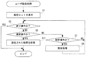
図6はユーザ設定処理のフロー図である。たとえば、使用者が図3(A)に示されるユーザ設定テーブルの内容を変更する操作を行うと、プロセッサ24はステップS1で設定GUIを表示させる。つまり、プロセッサ24は、ユーザ設定テーブルの各項目を設定可能にするGUIを、ディスプレイ30に表示する。続いて、ステップS3で終了操作か否かを判断する。つまり、ユーザ設定処理を終了する操作が、キー入力装置26に対して行われたか否かを判断する。ステップS3で“YES”であれば、つまり終了操作が行われていれば、ユーザ設定処理を終了する。
FIG. 6 is a flowchart of the user setting process. For example, when the user performs an operation of changing the contents of the user setting table shown in FIG. 3A, the
一方、ステップS3で“NO”であれば、つまり終了操作が行われていなければ、ステップS5で確定操作か否かを判断する。つまり、設定GUIに対する設定操作の結果を、確定する操作が行われたか否かを判断する。ステップS5で“NO”であれば、確定操作が行われていなければ、ステップS7で設定操作か否かを判断する。たとえば、図3(A)に示す「ディスプレイ(BL点灯)」の項目を設定するための操作が、キー入力装置26に対して行われたか否かを判断する。ステップS7で“NO”であれば、つまり設定操作が行われていなければ、ステップS3に戻る。一方、ステップS7で“YES”であれば、たとえば「ディスプレイ(BL点灯)」の項目を設定するための操作が行われていれば、ステップS9で設定処理を実行し、ステップS3に戻る。たとえば、キー入力装置26によって「5」が入力されていれば、図4に示すように、「ディスプレイ(BL点灯)」の項目が「5秒」に設定される。
On the other hand, if “NO” in the step S3, that is, if the ending operation is not performed, it is determined whether or not the confirming operation is performed in a step S5. That is, it is determined whether or not an operation for determining the result of the setting operation for the setting GUI has been performed. If “NO” in the step S5, if the confirming operation is not performed, it is determined whether or not the setting operation is performed in a step S7. For example, it is determined whether or not an operation for setting the item “display (BL lighting)” shown in FIG. If “NO” in the step S7, that is, if the setting operation is not performed, the process returns to the step S3. On the other hand, if “YES” in the step S7, for example, if an operation for setting the item “display (BL lighting)” is performed, the setting process is executed in a step S9, and the process returns to the step S3. For example, if “5” is input by the
また、ステップS5で“YES”であれば、つまり確定操作が行われていれば、ステップS11で設定された結果を記憶し、ユーザ設定処理を終了する。たとえば、「ディスプレイ(BL点灯)」の項目が「5秒」に設定されていれば、図4に示すユーザ設定テーブルをRAM38に記憶する。なお、ステップS11の処理を実行するプロセッサ24は第2記憶部として機能する。
If “YES” in the step S5, that is, if a confirming operation is performed, the result set in the step S11 is stored, and the user setting process is ended. For example, if the item “Display (BL is lit)” is set to “5 seconds”, the user setting table shown in FIG. The
図7は高輝度表示制御処理のフロー図である。プロセッサ24は、ディスプレイ30が高輝度表示に切り替えられ、高輝度フラグ340がオンにされると、ステップS21で省電力モードか否かを判断する。つまり、省電力フラグ336がオンであるか否かを判断する。ステップS21で“NO”であれば、つまり省電力モードが設定されていなければ、ステップS27に進む。一方、ステップS21で“YES”であれば、つまり省電力モードが設定されていれば、ステップS23でユーザ設定値が省電力設定値よりも小さいか否かを判断する。ステップS23では、まずユーザ設定テーブルにおける、「ディスプレイ(BL点灯)」の数値をユーザ設定値(第2設定時間)として読み出し、省電力テーブルにおける、「ディスプレイ(BL点灯)」の数値を省電力設定値(第1設定時間)として読み出す。そして、読み出したユーザ設定値が省電力設定値よりも小さいか否かを判断する。すなわち、プロセッサ24は、読み出したユーザ設定値による携帯電話機10の動作による消費電力が、省電力設定値による携帯電話機10の動作による消費電力より少ない消費電力となるか否かを判断する。なお、ステップS23の処理を実行するプロセッサ24は判断部として機能する。
FIG. 7 is a flowchart of the high luminance display control process. When the
たとえば、図3(A)および図3(B)のテーブルの「ディスプレイ(BL点灯)」に着目すると、ユーザ設定値は「30」となり、省電力設定値は「10」となる。そのため、ステップS23では“NO”と判断され、ステップS25で省電力設定値に基づいて閾値を設定する。つまり、ステップS25では、省電力設定値である「10」に基づいて、ディスプレイ30を低輝度表示(微灯状態)に切り替える判断を行うための閾値を算出し、算出された値を閾値バッファ330に格納する。つまり、ステップS25では、省電力テーブルから読み出された省電力設定値を特性時間として設定する。
For example, when attention is paid to “display (BL lighting)” in the tables of FIGS. 3A and 3B, the user setting value is “30” and the power saving setting value is “10”. Therefore, “NO” is determined in step S23, and a threshold is set based on the power saving setting value in step S25. That is, in step S25, based on “10” that is the power saving setting value, a threshold value for determining to switch the
また、図3(B)および図4のテーブルの「ディスプレイ(BL点灯)」に着目すれば、ユーザ設定値が「5」となり、省電力設定値が「10」となる。そのため、ステップS23では、“YES”と判断され、ステップS27でユーザ設定値に基づいて閾値を設定する。つまり、ステップS27では、ユーザ設置値である「5」に基づいて閾値を算出し、算出された値を閾値バッファ330に格納する。つまり、ステップS27では、ユーザ設定テーブルから読み出されたユーザ設定値を特定時間として設定する。なお、ステップS25の処理を実行するプロセッサ24は設定部として機能する。
If attention is paid to “display (BL lighting)” in the tables of FIGS. 3B and 4, the user setting value is “5” and the power saving setting value is “10”. Therefore, “YES” is determined in step S23, and a threshold is set based on the user set value in step S27. That is, in step S <b> 27, the threshold value is calculated based on “5” that is the user installation value, and the calculated value is stored in the
ステップS29では、操作されたか否かを判断する。つまり、キー入力装置26に対してキー入力操作が行われることで、キー操作フラグ338がオンにされたか否かを判断する。ステップS29で“YES”であれば、つまりキー入力操作が行われていれば、ステップS43に進む。一方、ステップS29で“NO”であれば、つまりキー入力操作が行われていなければ、ステップS31で着信したか否かを判断する。たとえば、無線通信回路14から音声着信が通知されたか否かを判断する。ステップS31で“YES”であれば、つまり無線通信回路14から着信が通知されていれば、ステップS43に進む。一方、ステップS31で“NO”であれば、つまり着信していなければステップS33に進む。
In step S29, it is determined whether or not an operation has been performed. That is, it is determined whether or not the
続いて、ステップS33では、充電フラグ346が変化したか否かを判断する。たとえば、携帯電話機10の端子Taおよび端子Tbに外部電源が接続されることで、二次電池50が充電状態となり、充電フラグ346がオンとなったか否かを判断する。ステップS33で“YES”であれば、たとえば二次電池50が充電状態となれば、ステップS43に進む。一方、ステップS33で“NO”であれば、つまり二次電池50に変化がなければ、ステップS35に進む。なお、二次電池50の充電が完了することで充電フラグ346がオンからオフに切り替わっても、ステップS33では“YES”と判断される。つまり、ステップS33では、二次電池50の充電が完了または終了すれば、“YES”と判断される。
Subsequently, in step S33, it is determined whether or not the
ステップS35では、閉状態にされたか否かを判断する。つまり、開閉フラグ344がオンからオフに切り替わったか否かを判断する。ステップS35で“YES”であれば、つまり携帯電話機10が開状態から閉状態にされると、ステップS45に進む。一方、ステップS35で“NO”であれば、たとえば携帯電話機10が開状態のままであれば、ステップS37で高輝度カウンタ348をインクリメントする。つまり、無操作状態でディスプレイ30の高輝度表示が維持される時間をカウントするために、高輝度カウンタ348はインクリメントされる。
In step S35, it is determined whether or not the closed state is established. That is, it is determined whether the open /
続いて、ステップS39では、高輝度カウンタ348の値が閾値よりも大きいか否かを判断する。たとえば、閾値が5秒に相当する値であれば、高輝度カウンタ348の値が5秒に相当する値よりも大きいか否かを判断する。つまり、ステップS39では、ディスプレイ30の高輝度状態が、無操作状態で特定時間(ここでは、5秒)より長い時間維持されたか否かを判断する。ステップS39で“YES”であれば、つまり高輝度カウンタ348の値が5秒に相当する値よりも大きければ、ステップS41でディスプレイ30を微灯状態に設定する。つまり、プロセッサ24は、ディスプレイ30を低輝度表示に切り替える命令をBL制御回路32に発行する。そして、ステップS41の処理が終了すると高輝度表示処理を終了する。なお、ステップS41の処理によってディスプレイ30が低輝度表示に切り替えられると、低輝度フラグ342がオンにされる。
Subsequently, in step S39, it is determined whether or not the value of the
また、ステップS39で“NO”であれば、つまりディスプレイ30が高輝度表示にされてから、無操作状態で5秒間経過していなければステップS29に戻る。つまり、ステップS29以降の処理を繰り返す。また、ステップS29-S33のいずれかで“YES”であれば、つまりディスプレイ30が高輝度表示にされ、キー入力操作、音声着信または二次電池50の充電開始/終了が検出されれば、ステップS43で高輝度カウンタ348の値をリセットする。つまり、使用者によって携帯電話機10が操作されている途中に、ディスプレイ30が低輝度表示に切り替わらないようにするために、高輝度カウンタ348はリセットされる。そして、プロセッサ24は、ステップS43の処理が終了すると、ステップS21に戻る。これは、キー入力操作によって省電力モードの設定が変更される可能性があるため、高輝度カウンタ348がリセットされると、プロセッサ24はステップS21の処理に戻る。
On the other hand, if “NO” in the step S39, that is, if the
また、ステップS29−S39の処理が繰り返して実行されている途中に、携帯電話機10が開状態から閉状態にされるとステップS35で“YES”と判断され、ステップS45でクローズが有効であるか否かを判断する。たとえば、省電力モードが設定されていなければ、図4に示す「クローズ」の項目が「ON」であるか否かを判断する。つまり、ステップS45ではクローズ機能が有効にされているか否かを判断する。ステップS45で“NO”であれば、つまりクローズ機能が有効にされていなければ、ステップS37に戻る。一方、ステップS45で“YES”であれば、つまりクローズ機能が有効にされていれば、ステップS47でタイマ処理を実行する。つまり、携帯電話機10が閉状態になると同時にディスプレイ30およびバックライト34の電源がオフにされないようにするため、2秒間のタイマ処理が実行される。そして、ステップS45で2秒間のタイマ処理が実行されると、ステップS49でディスプレイ30およびバックライト34の電源をオフにして、高輝度表示制御処理を終了する。つまり、ステップS49の処理が実行されると、ディスプレイ30の表示が消去される。
Further, if the mobile phone 10 is changed from the open state to the closed state while the processes of steps S29 to S39 are being repeatedly executed, “YES” is determined in step S35, and whether the close is valid in step S45. Judge whether or not. For example, if the power saving mode is not set, it is determined whether or not the “close” item shown in FIG. 4 is “ON”. That is, in step S45, it is determined whether or not the close function is enabled. If “NO” in the step S45, that is, if the close function is not enabled, the process returns to the step S37. On the other hand, if “YES” in the step S45, that is, if the close function is enabled, a timer process is executed in a step S47. That is, a 2-second timer process is executed to prevent the power of the
なお、ステップS29−S39の処理は、約10ms毎に繰り返される。そのため、高輝度カウンタ348は10ms毎にカウント(インクリメント)される。したがって、特定時間が5秒であれば、閾値は「500」となる。ただし、他の実施例では、ステップS29-S39の繰り返しが1秒毎に行われるようにタイマ処理を実行することで、ユーザ設定値または省電力設定値をそのまま閾値として設定できるようにしてもよい。
In addition, the process of step S29-S39 is repeated about every 10 ms. Therefore, the
また、低輝度表示処理は、高輝度表示処理のフロー図とおおむね同じであるため、フローの図示は省略する。低輝度表示処理において、ステップS23に相当する処理では、各テーブルの「ディスプレイ(微灯)」の項目が比較され、ステップS25,S27に相当する処理では、上記項目の数値に基づいて特定時間が設定される。また、ステップS37,S39,S43に相当する処理では、高輝度カウンタ348に代えて低輝度カウンタ(図示せず)の値がインクリメント、比較またはリセットされる。そして、ステップS39で“YES”と判断された場合には、ステップS41の処理ではなく、ステップS49に相当する処理が実行される。つまり、ディスプレイ30が低輝度表示の場合に、特定時間が経過すると、ディスプレイ30およびバックライト34の電源がオフにされる。
Further, the low luminance display process is almost the same as the flow chart of the high luminance display process, and thus the flow is not shown. In the low luminance display process, in the process corresponding to step S23, the item of “display (light)” in each table is compared. In the process corresponding to steps S25 and S27, the specific time is based on the numerical value of the above item. Is set. In the processing corresponding to steps S37, S39, and S43, the value of a low luminance counter (not shown) is incremented, compared, or reset instead of the
以上の説明から分かるように、携帯電話機10は、キー入力装置26、ディスプレイ30およびRAM38などを備える。また、省電力モードが設定可能な携帯電話機10は、ディスプレイ30が高輝度表示で、キー入力操作が行われないまま、特定時間が経過すると、省電力状態に遷移する。RAM38には、ユーザ設定値および省電力設定値が読み出される2つのテーブルが記憶される。使用者によって任意に設定された時間は、ユーザ設定値としてRAM38のユーザ設定テーブルに記憶される。そして、携帯電話機10に省電力モードが設定され、ディスプレイ30が高輝度表示に切り替えられると、プロセッサ24はユーザ設定値が省電力設定値より短ければ、ユーザ設定値を特定時間として設定する。
As can be seen from the above description, the cellular phone 10 includes the
たとえば、各テーブルの「ディスプレイ(BL点灯)」に着目する場合には、ユーザ設定値として「5秒」が読み出され、省電力設定値として「10秒」が読み出される。そして、特定時間は「10秒」に設定される。 For example, when paying attention to “display (BL lighting)” of each table, “5 seconds” is read as the user setting value, and “10 seconds” is read as the power saving setting value. The specific time is set to “10 seconds”.
これにより、省電力モードの設定よりも、使用者による設定の方が消費電力を抑えることができれば、使用者の設定が優先される。 As a result, if the setting by the user can suppress the power consumption rather than the setting of the power saving mode, the setting by the user is given priority.
なお、他の実施例では、ユーザ設定テーブルおよび省電力テーブルに、メール着信時の鳴動設定などが含まれていてもよい。 In other embodiments, the user setting table and the power saving table may include ringing settings for incoming mail.
また、メール着信時の鳴動設定や、ランプの設定などでも、高輝度表示処理と同様、使用者による設定が優先されてもよい。 In addition, the setting by the user may be given priority in the ringing setting at the time of incoming mail, the lamp setting, etc., as in the high-intensity display process.
また、音声着信音や、フィードバック音などの出力を禁止するマナーモードが設定可能な場合、キー操作音が「ON」にされていても、フィードバック音を出力せずに、マナーモードの設定が優先される。 In addition, if the manner mode that prohibits the output of voice ringtones and feedback sounds can be set, the manner mode setting is given priority without outputting the feedback sound even if the key operation sound is set to “ON”. Is done.
また、携帯電話機10の通信方式はCDMA方式に限らず、LTE(Long Term Evolution)方式、W-CDMA方式、GSM方式、TDMA方式、FDMA方式およびPHS方式などを採用してもよい。さらに、ディスプレイ30にはLCDモニタが利用されるが、有機ELパネルなどの他の表示装置が利用されてもよい。
Further, the communication method of the mobile phone 10 is not limited to the CDMA method, and an LTE (Long Term Evolution) method, a W-CDMA method, a GSM method, a TDMA method, an FDMA method, a PHS method, or the like may be adopted. Furthermore, although an LCD monitor is used for the
また、二次電池50としてリチウムイオン電池を採用したが、鉛蓄電池、ニッケル水素電池、ナトリウムイオン電池、金属空気電池および亜鉛臭素電池などであってもよい。また、二次電池50に代えて、アルカリ電池などの1次電池または燃料電池などが採用されてもよい。
Moreover, although the lithium ion battery was employ | adopted as the
また、携帯電話機10の形状は、2つの筐体のスライド型であったが、3つ以上の筐体のスライド型であってもよい。さらに、携帯電話機10の形状は、1軸の折り畳み型、2軸の折り畳み型や、ストレート型およびリボルバー型などであってもよい。 Further, the shape of the mobile phone 10 is a slide type with two casings, but may be a slide type with three or more casings. Furthermore, the shape of the mobile phone 10 may be a uniaxial folding type, a biaxial folding type, a straight type, a revolver type, or the like.
さらに、本願発明は、携帯電話機10のみに限らず、スマートフォン、PDA(Personal Digital Assistant)およびノート型PC(ネットブックなども含む)に適用されてもよい。 Furthermore, the present invention may be applied not only to the mobile phone 10 but also to a smartphone, a PDA (Personal Digital Assistant), and a notebook PC (including a netbook).
そして、本明細書中で挙げた、時間および閾値などの具体的な数値は、いずれも単なる一例であり、製品の仕様などの必要に応じて適宜変更可能である。 The specific numerical values such as the time and the threshold value given in the present specification are merely examples, and can be appropriately changed according to the specifications of the product.
10 … 携帯電話機
12 … アンテナ
14 … 無線通信回路
24 … プロセッサ
26 … キー入力装置
30 … ディスプレイ
32 … BL制御回路
34 … バックライト
48 … 電源回路
50 … 二次電池
DESCRIPTION OF SYMBOLS 10 ...
Claims (3)
前記省電力モードにおいて、前記省電力状態に遷移させるための時間を第1設定時間として記憶する第1記憶部、
任意に設定された時間を、前記省電力状態に遷移させるための第2設定時間として記憶する第2記憶部、
前記省電力モードが設定され、さらに前記特定状態のとき、前記第2設定時間が前記第1設定時間よりも短いか否かを判断する判断部、および
前記判断部によって前記第2設定時間が前記第1設定時間よりも短いと判断されたと
き、前記第2設定時間を前記特定時間として設定する設定部を備える、携帯電話機。 A mobile phone that can set a power saving mode that reduces power consumption, and transitions to a power saving state when a specific time elapses in a specific state,
In the power saving mode, a first storage unit that stores a time for shifting to the power saving state as a first set time;
A second storage unit that stores an arbitrarily set time as a second set time for transitioning to the power saving state;
When the power saving mode is set and in the specific state, the determination unit determines whether the second setting time is shorter than the first setting time, and the determination unit determines the second setting time A mobile phone comprising a setting unit that sets the second set time as the specific time when it is determined that the set time is shorter than the first set time.
任意に設定された時間を、前記省電力状態に遷移させるための第2設定時間として記憶する記憶部、
前記省電力モードが設定され、さらに前記特定状態のとき、前記第2設定時間が前記第1設定時間よりも短いか否かを判断する判断部、および
前記判断部によって前記第2設定時間が前記第1設定時間よりも短いと判断されたと
き、前記第2設定時間を前記特定時間として設定する設定部として機能させる、省電力制御プログラム。 A power saving mode that suppresses power consumption can be set. When a specific time elapses in a specific state, the power saving mode is entered. In the power saving mode, a time for changing to the power saving state is stored as a first setting time. Mobile phone processor,
A storage unit that stores an arbitrarily set time as a second set time for transitioning to the power saving state,
When the power saving mode is set and in the specific state, the determination unit determines whether the second setting time is shorter than the first setting time, and the determination unit determines the second setting time A power saving control program for causing a function to function as a setting unit that sets the second set time as the specific time when it is determined that the set time is shorter than the first set time.
任意に設定された時間を、前記省電力状態に遷移させるための第2設定時間として記憶し、
前記省電力モードが設定され、さらに前記特定状態のとき、前記第2設定時間が前記第1設定時間よりも短いか否かを判断し、そして
前記第2設定時間が前記第1設定時間よりも短いと判断されたとき、前記第2設定時間を前記特定時間として設定する、省電力制御方法。 A power saving mode that suppresses power consumption can be set. When a specific time elapses in a specific state, the power saving mode is entered. In the power saving mode, a time for changing to the power saving state is stored as a first setting time. A power saving control method for a mobile phone,
An arbitrarily set time is stored as a second set time for transitioning to the power saving state,
When the power saving mode is set and the specific state is set, it is determined whether the second set time is shorter than the first set time, and the second set time is shorter than the first set time. A power saving control method for setting the second set time as the specific time when it is determined to be short.
Priority Applications (1)
| Application Number | Priority Date | Filing Date | Title |
|---|---|---|---|
| JP2010099614A JP5341815B2 (en) | 2010-04-23 | 2010-04-23 | Mobile phone, power saving control program, and power saving control method |
Applications Claiming Priority (1)
| Application Number | Priority Date | Filing Date | Title |
|---|---|---|---|
| JP2010099614A JP5341815B2 (en) | 2010-04-23 | 2010-04-23 | Mobile phone, power saving control program, and power saving control method |
Publications (3)
| Publication Number | Publication Date |
|---|---|
| JP2011233948A JP2011233948A (en) | 2011-11-17 |
| JP2011233948A5 JP2011233948A5 (en) | 2013-03-21 |
| JP5341815B2 true JP5341815B2 (en) | 2013-11-13 |
Family
ID=45322875
Family Applications (1)
| Application Number | Title | Priority Date | Filing Date |
|---|---|---|---|
| JP2010099614A Expired - Fee Related JP5341815B2 (en) | 2010-04-23 | 2010-04-23 | Mobile phone, power saving control program, and power saving control method |
Country Status (1)
| Country | Link |
|---|---|
| JP (1) | JP5341815B2 (en) |
Cited By (2)
| Publication number | Priority date | Publication date | Assignee | Title |
|---|---|---|---|---|
| US9879898B2 (en) | 2005-05-18 | 2018-01-30 | Whirlpool Corporation | Insulated ice compartment for bottom mount refrigerator with controlled damper |
| JP7159781B2 (en) | 2018-10-17 | 2022-10-25 | 三菱電機株式会社 | refrigerator |
Families Citing this family (4)
| Publication number | Priority date | Publication date | Assignee | Title |
|---|---|---|---|---|
| JP2013132126A (en) * | 2011-12-21 | 2013-07-04 | Canon Inc | Electronic apparatus |
| JP5883363B2 (en) * | 2012-08-10 | 2016-03-15 | 株式会社中電工 | Power supply for lighting and polarity test |
| JP5901479B2 (en) * | 2012-09-13 | 2016-04-13 | シャープ株式会社 | Portable information terminal, its control method, and computer program for portable information terminal |
| JP6068283B2 (en) * | 2013-07-29 | 2017-01-25 | 京セラ株式会社 | Mobile terminal device |
Family Cites Families (1)
| Publication number | Priority date | Publication date | Assignee | Title |
|---|---|---|---|---|
| JP2009168866A (en) * | 2008-01-11 | 2009-07-30 | Kyocera Mita Corp | Image forming apparatus and power saving management system |
-
2010
- 2010-04-23 JP JP2010099614A patent/JP5341815B2/en not_active Expired - Fee Related
Cited By (2)
| Publication number | Priority date | Publication date | Assignee | Title |
|---|---|---|---|---|
| US9879898B2 (en) | 2005-05-18 | 2018-01-30 | Whirlpool Corporation | Insulated ice compartment for bottom mount refrigerator with controlled damper |
| JP7159781B2 (en) | 2018-10-17 | 2022-10-25 | 三菱電機株式会社 | refrigerator |
Also Published As
| Publication number | Publication date |
|---|---|
| JP2011233948A (en) | 2011-11-17 |
Similar Documents
| Publication | Publication Date | Title |
|---|---|---|
| JP5341815B2 (en) | Mobile phone, power saving control program, and power saving control method | |
| US6959208B2 (en) | Portable terminal | |
| JP5487575B2 (en) | Mobile phone with key backlight and information notification method using key backlight | |
| CN102646018A (en) | Method and device for controlling display size of mobile terminal screen | |
| JP5663138B2 (en) | Mobile terminal, incoming notification method and program for mobile terminal | |
| JP4240915B2 (en) | Communication terminal | |
| JP5443830B2 (en) | Mobile terminal and slide control program | |
| JP2009219163A (en) | Electronic equipment | |
| JP2011066754A (en) | Mobile communication terminal, display control program, and display control method | |
| JP5416035B2 (en) | Mobile communication terminal, flashing cycle control program, and flashing cycle control method | |
| JP2004104245A (en) | Mobile terminal | |
| JP2004153756A (en) | Portable apparatus | |
| JP2002101193A (en) | Portable telephone | |
| JP4411352B2 (en) | Communication terminal | |
| JP2003273970A (en) | Communication terminal | |
| JP2013207419A (en) | Portable terminal device and notification method | |
| JP5093193B2 (en) | Wireless communication terminal and mobile phone | |
| JP4804519B2 (en) | Mobile communication terminal and control method | |
| TWI449029B (en) | Display device and method for using the same | |
| JP2009147777A (en) | Mobile terminal device | |
| JP4514815B2 (en) | Portable electronic device and display control method thereof | |
| JP4338027B2 (en) | Portable terminal device and display control method thereof | |
| KR100681192B1 (en) | Low Power Consumption Mobile Communication Terminal and Informing Method of Receipt Using the same | |
| JP2002353882A (en) | Portable information terminal equipment | |
| JP2012010230A (en) | Mobile terminal, brightness control program and brightness control method |
Legal Events
| Date | Code | Title | Description |
|---|---|---|---|
| A521 | Request for written amendment filed |
Free format text: JAPANESE INTERMEDIATE CODE: A523 Effective date: 20130201 |
|
| A621 | Written request for application examination |
Free format text: JAPANESE INTERMEDIATE CODE: A621 Effective date: 20130215 |
|
| A977 | Report on retrieval |
Free format text: JAPANESE INTERMEDIATE CODE: A971007 Effective date: 20130716 |
|
| TRDD | Decision of grant or rejection written | ||
| A01 | Written decision to grant a patent or to grant a registration (utility model) |
Free format text: JAPANESE INTERMEDIATE CODE: A01 Effective date: 20130723 |
|
| A61 | First payment of annual fees (during grant procedure) |
Free format text: JAPANESE INTERMEDIATE CODE: A61 Effective date: 20130808 |
|
| R150 | Certificate of patent or registration of utility model |
Ref document number: 5341815 Country of ref document: JP Free format text: JAPANESE INTERMEDIATE CODE: R150 Free format text: JAPANESE INTERMEDIATE CODE: R150 |
|
| LAPS | Cancellation because of no payment of annual fees |