JP5339667B2 - Information processing apparatus and method - Google Patents
Information processing apparatus and method Download PDFInfo
- Publication number
- JP5339667B2 JP5339667B2 JP2006100389A JP2006100389A JP5339667B2 JP 5339667 B2 JP5339667 B2 JP 5339667B2 JP 2006100389 A JP2006100389 A JP 2006100389A JP 2006100389 A JP2006100389 A JP 2006100389A JP 5339667 B2 JP5339667 B2 JP 5339667B2
- Authority
- JP
- Japan
- Prior art keywords
- character object
- information processing
- area
- processing apparatus
- structured document
- Prior art date
- Legal status (The legal status is an assumption and is not a legal conclusion. Google has not performed a legal analysis and makes no representation as to the accuracy of the status listed.)
- Expired - Fee Related
Links
Images


Classifications
-
- G—PHYSICS
- G06—COMPUTING; CALCULATING OR COUNTING
- G06T—IMAGE DATA PROCESSING OR GENERATION, IN GENERAL
- G06T11/00—2D [Two Dimensional] image generation
- G06T11/60—Editing figures and text; Combining figures or text
Description
本発明は、構造化文書で記述された複数のオブジェクトからなるベクタ画像を処理可能な情報処理装置及びその方法に関するものである。 The present invention relates to an information processing apparatus and method capable of processing a vector image composed of a plurality of objects described in a structured document.
ベクタ形式の画像は、解像度によらず高品位な表示が得られる等のメリットがある。このようなベクタ形式の画像を作成、編集するグラフィックス描画アプリケーションソフトとして、例えばAdobe Systems社のイラストレータ(登録商標)が挙げられる。このAdobe Systems社のイラストレータ(登録商標)は、その指定領域内のオブジェクトを移動させて編集することが可能である。例えば、ベクタ画像を高速に描画する技術として、特許文献1がある。
XMLベースでベクタ画像を表現するための言語として、SVGが存在する。例えば、図1に示すベクタ画像を記述したSVGファイルを、処理能力の低い機器に通信ネットワークを介して転送した場合を想定する。この場合、本来送信する必要のあるグラフィック領域が領域1003だとしても、図1のオブジェクト1000〜1002のすべてをグラフィック化しなければならず機器に負担がかかってしまう。また、機器のメモリの容量もその分必要となり、転送時間もかかってしまう。特に図2乃至図4のように、指定領域2000,3000,4001に含まれる図形や文字のオブジェクトの部分が少ない場合には、不要なデータで多くの記憶容量を消費する場合が考えられる。
SVG exists as a language for expressing vector images based on XML. For example, it is assumed that the SVG file describing the vector image shown in FIG. 1 is transferred to a device with low processing capability via a communication network. In this case, even if the graphic area that should originally be transmitted is the
本発明は、上記従来技術の欠点を解決することにある。 The present invention is to solve the above-mentioned drawbacks of the prior art.
また本願発明の特徴は、複数のオブジェクトを含むベクタ画像において、指定領域に含まれるグラフィックスデータだけをベクトルデータとして抽出して保存する情報処理装置及びその方法を提供することにある。 A feature of the present invention is to provide an information processing apparatus and method for extracting and storing only graphics data included in a designated area as vector data in a vector image including a plurality of objects.
上記目的を達成するために本発明の一態様に係る情報処理装置は以下のような構成を備える。即ち、ベクタ画像を記述した構造化文書を処理する情報処理装置であって、
前記構造化文書を解析して得られた前記ベクタ画像を表示部に表示させる表示手段と、前記表示部においてユーザにより指定された領域を検出する検出手段と、前記ベクタ画像に含まれる文字オブジェクトの一部が前記指定された領域に含まれるか否かを判定する判定手段と、前記判定手段によって前記指定された領域に含まれると判定された前記文字オブジェクトと前記指定された領域の外縁との交差点の座標を、前記文字オブジェクトの種類および前記文字オブジェクトの前記ベクタ画像の座標に基づいて決定する決定手段と、前記決定手段によって決定された前記交差点の座標に基づき前記文字オブジェクトの記述を変更することにより、(i)前記判定手段によって前記指定された領域に含まれないと判定された文字オブジェクトの記述が削除され前記指定された領域内のベクタ画像を記述し且つ(ii)前記指定された領域内に含まれると判定された文字オブジェクトの少なくとも一部を曲線で近似することによって得られる文字オブジェクトを記述した構造化文書を作成する作成手段と、を有することを特徴とする。
In order to achieve the above object, an information processing apparatus according to an aspect of the present invention has the following arrangement. That is, an information processing apparatus that processes a structured document describing a vector image,
Display means for displaying the vector image obtained by analyzing the structured document on a display section, detection means for detecting an area designated by the user in the display section, and character objects included in the vector image A determination means for determining whether or not a part is included in the specified area; and the character object determined to be included in the specified area by the determination means and an outer edge of the specified area change intersection coordinates, and determining means for determining based on the coordinates of the vector image image of the character object type and the character object, the description of the character object based on the coordinate of the intersection determined by the determination means (I) The character object determined to be not included in the designated area by the determination means Character obtained by approximating at least a portion of the write vector image in description is given prior SL is deleted regions and (ii) determined character objects to be included in the designated region in the curve And a creation means for creating a structured document describing the object .
尚、この課題を解決するための手段は、本願発明の特徴の全てを列挙しているものではなく、特許請求の範囲に記載された他の請求項及びそれら特徴群の組み合わせも発明になり得る。 The means for solving this problem does not enumerate all the features of the present invention, and other claims described in the claims and combinations of these feature groups can also be the invention. .
本発明によれば、複数のオブジェクトを含むベクタ画像において、指定領域に含まれるベクタ画像を抽出し、抽出したベクタ画像に対応する構造化文書を作成して保存できるという効果がある。その結果、機器の処理の負担が軽減される。 According to the present invention, there is an effect that a vector image included in a designated area can be extracted from a vector image including a plurality of objects, and a structured document corresponding to the extracted vector image can be created and stored. As a result, the processing burden on the device is reduced.
以下、添付図面を参照して本発明の好適な実施の形態を詳しく説明する。尚、以下の実施の形態は特許請求の範囲に係る本発明を限定するものでなく、また本実施の形態で説明されている特徴の組み合わせの全てが本発明の解決手段に必須のものとは限らない。 Hereinafter, preferred embodiments of the present invention will be described in detail with reference to the accompanying drawings. The following embodiments do not limit the present invention according to the claims, and all combinations of features described in the present embodiments are essential to the solution means of the present invention. Not exclusively.
図5は、本発明の実施の形態に係るシステムの概要を示した構成図である。 FIG. 5 is a configuration diagram showing an outline of the system according to the embodiment of the present invention.
図5において、スキャナ101はLAN102に接続されている。LAN102には、クライアントとしてのPC103、ネットワークプリンタ104、ファイルサーバ105が接続されている。
In FIG. 5, the
図6は、本実施の形態に係る情報処理装置(PC)103の構成を示すブロック図である。 FIG. 6 is a block diagram showing a configuration of the information processing apparatus (PC) 103 according to the present embodiment.
図6において、CPU201はシステム制御部であり、この情報処理装置103の全体を制御している。ROM202は、CPU201の制御プログラムや各種固定データを格納している。RAM203は、SRAMやDRAM等で構成され、CPU201による制御処理の実行時にプログラム制御変数等を格納する。また各種設定パラメータ、各種ワーク用バッファも、このRAM203に格納される。記憶部204はハードディスク(HD)等で構成され、文書や画像等のスキャン画像を格納する。操作パネル206は、キーボード、タッチパネル等で構成され、オペレータが各種入力操作を行うのに使用される。表示部207は、液晶等で構成され、オペレータに提示するメッセージやメニューコマンド等を表示する。LANi/f208は、LAN209に接続するためのインターフェースである。USBi/f210は、USB回線211に接続するためのインターフェースである。
In FIG. 6, a
以上の構成において、ユーザは、操作パネル206を用いて、表示部207に表示されているベクタ画像画像内の一部分の範囲を領域指定する。そして、その指定領域の位置に基づいて得られたベクタ画像を、LAN102を介してプリンタ104、ファイルサーバ105に転送することができる。
In the above configuration, the user uses the
ここでは構造化文書としてXMLベースで記述されたSVGを取り上げ、スキャナ101によって読み取った画像をベクトルデータであるSVG形式で保存し、そのベクタ画像から指定範囲の画像を抽出する例について説明する。
Here, an example will be described in which an SVG described in an XML base is taken as a structured document, an image read by the
図7(A)(B)は、本実施の形態に係るベクタ画像(A)とそのSVG形式の構造化文書(B)の一例を示す図である。 FIGS. 7A and 7B are diagrams showing an example of a vector image (A) and a structured document (B) in the SVG format according to the present embodiment.
図7(A)に示すベクタ画像には、図形や文字、イメージのオブジェクトが複数含まれている。例えば、このベクタ画像から図7(A)の点線の矩形700で示した指定した領域のベクタ画像を記述した構造化文書データを新たに作成する例を説明する。図7(A)のベクタ画像は、オブジェクトとして、図形701、文字702、ラスタ画像703を有している。なお、ラスタ画像703はもちろんベクタ画像として直接SVG形式で記述することはできないが、ラスタ画像を外部参照する記述を行うことでききるので、1つのオブジェクトとしてラスタ画像を取り上げることとする。
The vector image shown in FIG. 7A includes a plurality of graphics, characters, and image objects. For example, an example will be described in which structured document data in which a vector image of a specified area indicated by a
図7(B)において、構造化文書データ710は図形701の円を記述したものであり、構造化文書データ711は画像703を記述したものであり、構造化文書データ712は文字702を記述したものであり、そして構造化文書データ713は図形701の矩形を記述したものである。
In FIG. 7B, structured
図8は、例えば図7(A)に示すようなSVG形式で記述されたベクタ画像から、ユーザによって指定された領域700の画像を抽出する手順を説明するフローチャートである。
FIG. 8 is a flowchart illustrating a procedure for extracting an image of the
図9は、図8のステップS104の各オブジェクトの処理手順を説明するフローチャートである。 FIG. 9 is a flowchart for explaining the processing procedure of each object in step S104 of FIG.
まず図8において、ステップS102で、CPU201は、図7(B)のベクタ画像の構造化文書データからオブジェクト化した構造化データを生成してRAM203に保存する。この構造化データは図10に示すDOM形式のオブジェクトデータである。
First, in FIG. 8, in step S <b> 102, the
図10は、図7(A)に示すベクタ画像に配置されるオブジェクトをDOM形式のデータとして構造的に表した図である。 FIG. 10 is a diagram structurally representing the objects arranged in the vector image shown in FIG. 7A as DOM format data.
DOM形式のデータをメモリに保存する際に、CPU201は、構造化文書データに記述されているオブジェクトの色や座標のデータも同様にRAM203に保存する。なお、CPU201は、DOM形式のデータを生成しないで、構造化文書データが記述してあるファイルを直接読み込むことで処理する場合も考えられる。尚、図10において、「circle」は、図7(A)の円に、「image」は図7(A)の画像703に、「text」は文字702に、そして「g」に属している「rect」はそれぞれ図形701の矩形に対応している。
When the DOM format data is stored in the memory, the
次にステップS103で、CPU201は、図7(A)に示す領域700のように、オペレータが操作パネル206を用いて領域を指定したことを検出する。そしてCPU201は、指定された領域のベクタ画像内の座標位置に関する情報(具体的には左上の座標位置情報および領域の高さと幅に関する情報)を取得する。次にステップS104で、CPU201は、DOM形式のデータとなった各図形に対して図9に示す処理を行う。
In step S103, the
図9では、まずステップS202で、CPU201は、指定領域700にオブジェクトの全部又は一部分が含まれるか否かを判定する。この判定は、オペレータが指定した領域700の座標位置情報とベクタ画像上に配置されているオブジェクトの座標位置情報に基づいて判定される。そのCPU201は、ここで指定された領域700内に含まれないと判定したオブジェクトを、図10のDOM形式のデータから削除する。図11は、変更後のDOM形式のデータである(S203)。
In FIG. 9, first, in step S <b> 202, the
図7(A)の例では、図形701の円と、一番右上の矩形が領域700に含まれていない。そのため、図11では、図形701の円に対応する「circle」と右上の矩形に対応する「rect」とが図10から除去されて図11に示されている。
In the example of FIG. 7A, the circle of the graphic 701 and the upper right rectangle are not included in the
ステップS204では、CPU201は、指定領域内にオブジェクトの全部が含まれていると判定するとそのまま処理を終了する。一方、全部ではなく一部分だけが含まれている場合はステップS205に処理が進む。ステップS205では、CPU201は、そのオブジェクトが図形のオブジェクトか否か判定する。ここで図形のオブジェクトであればステップS207に処理が進み、CPU201は、そのオブジェクトの指定領域内に含まれる形状に、そのオブジェクトを加工する。図7(A)の例では、図形701の矩形の一部が指定領域700に含まれている。
In step S204 , if the
図12(A)(B)及び図13(A)(B)は、本実施の形態に係る図形オブジェクトの加工例を説明する図である。 FIGS. 12A and 12B and FIGS. 13A and 13B are diagrams for explaining a processing example of the graphic object according to the present embodiment.
図12(A)は、図形オブジェクト1200と指定領域1201との関係を示す図、図12(B)は、この図形のオブジェクト1200を記述した構造化文書データを示している。
FIG. 12A shows the relationship between the
ここで、この図形1200は、座標位置情報として、点(100,100)、点(200,300)、点(300,100)、点(400,300)、点(500,100)、点(600,300)を結ぶ線分で構成されたオブジェクトを示している。 Here, the figure 1200 includes, as coordinate position information, a point (100, 100), a point (200, 300), a point (300, 100), a point (400, 300), a point (500, 100), a point ( 600, 300) shows an object composed of line segments.
図13(A)(B)は、この図形オブジェクト1200を指定領域1201で抽出した例を示している。
FIGS. 13A and 13B show an example in which this
図13(B)は、指定された領域内に含まれる図形1202を記述した構造化文書データを示している。ここでは、指定された領域を基準とした座標位置情報などを用いて、点(0,200)、点(50,100)、そして点(150,300)を結ぶ線で表されている。例えば、図13(A)における点Aの座標は、図形オブジェクト1200と指定領域1201の相対関係からそれらの座標位置情報を用いることにより求めることができる。点Aは指定領域の左上の座標(450,0)を基準としているため、点AのX座標は0となる。なお、点AのY座標は200となる。
FIG. 13B shows structured document data describing a graphic 1202 included in a designated area. Here, it is represented by a line connecting the point (0, 200), the point (50, 100), and the point (150, 300) using coordinate position information based on the designated area. For example, the coordinates of the point A in FIG. 13A can be obtained from the relative relationship between the
図14は、四角形の図形オブジェクトの加工例を示す図である。 FIG. 14 is a diagram illustrating an example of processing a rectangular graphic object.
図14に示すように、矩形の図形オブジェクト1400の内、指定領域1401に含まれる図形1402が抽出される。ここで、図14における点Aと点Bの座標は、ベクタ画像内で図形オブジェクト1400が配置されている座標位置情報と、指定領域1401の座標位置情報とを用いることにより求られる。そして、これら点Aと点Cとをつないだ直線と、直線CDと、直線DBの3本の直線を形成することにより、抽出された図形のオブジェクト1402の形状を求められる。
As shown in FIG. 14, a graphic 1402 included in a designated area 1401 is extracted from a rectangular
なお、図14に示す図形オブジェクト1400のSVG形式の記述は、
<svg>
<rect x=“10” y=“10” width=“100” height=“30” stroke=“black”
stroke-width=“10” fill=“none”/>
</svg>
であり、抽出された図形オブジェクト1402のSVG形式の記述は、
<svg>
<polyline fill=“none” stroke=“black” stroke-width=“10”
points=“0,60 30,60 30,90 0,90”/>
</svg>
となる。
The description in the SVG format of the
<Svg>
<Rect x = “10” y = “10” width = “100” height = “30” stroke = “black”
stroke-width = “10” fill = “none” / >
</ Svg>
The description of the extracted
<Svg>
<Polyline fill = “none” stroke = “black” stroke-width = “10”
points = “0,60 30,60 30,90 0,90” / >
</ Svg>
It becomes.
なお、図14に示す例では、ベクタ画像内における指定領域1401の左上の座標位置は(80,−40)であり、幅130,高さ130としている。 In the example shown in FIG. 14, the upper left coordinate position of the designated area 1401 in the vector image is (80, −40), and the width is 130 and the height is 130.
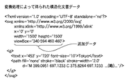
図15は、円の図形オブジェクトの加工例を説明する図である。 FIG. 15 is a diagram for explaining a processing example of a circular graphic object.
図15のように、円の図形オブジェクト1500のうち、指定領域1501に含まれる形状を部分的に抽出したオブジェクトが作成される。ここで図15における点Aと点Bの座標は、図形オブジェクト1500を描画している座標と、指定領域1501の座標とを用いることにより求められる。そして、これら点Aと点Bとを端点とし、図15のように円オブジェクト1500の中心と反対側の外側方向の方向点をもつ3次のベジェ曲線1502が形成される。こうして円オブジェクト1500の形状の内、指定領域1501で抽出された図形の形状を求めることができる。
As shown in FIG. 15, an object in which a shape included in the designated area 1501 is partially extracted from a circular
なお、図15に示す図形オブジェクト1500のSVG形式の記述は、
<svg>
<circle fill=“none” stroke=“black” stroke-width=“10” cx=“144.5” cy=“147” r=“144”/>
</svg>
であり、抽出された図形オブジェクト1502のSVG形式の記述は、
<svg>
<path fill=“none” stroke=“black” stroke-width=“10”
d=“M185, 247c0-79.5-64.5-144-144-144c-15.7, 0-30.8, 2.5-45, 7.2”/>
</svg>
となる。
In addition, the description of the SVG format of the
<Svg>
<Circle fill = “none” stroke = “black” stroke-width = “10” cx = “144.5” cy = “147” r = “144” />
</ Svg>
The description of the extracted
<Svg>
<Path fill = “none” stroke = “black” stroke-width = “10”
d = “M185, 247c0-79.5-64.5-144-144-144c-15.7, 0-30.8, 2.5-45, 7.2” />
</ Svg>
It becomes.
なお、図15に示す例では、ベクタ画像内における指定領域1401の左上の座標位置は(80,−100)であり、幅200,高さ200としている。 In the example shown in FIG. 15, the upper left coordinate position of the designated area 1401 in the vector image is (80, −100), and the width is 200 and the height is 200.
ステップS205で、CPU201は、オブジェクトが図形のオブジェクトではないと判定するとステップS206に処理が進む。そして、ステップS206において、CPU201は、文字のオブジェクトを含むか否か判定する。ここでもしCPU201は、文字のオブジェクトを含むと判定した場合ステップS209に処理が進む。ステップS209において、CPU201は、そのオブジェクトの指定領域内に含まれる形状にオブジェクトを加工する。
If the
図16は、文字オブジェクト加工を説明する図である。 FIG. 16 is a diagram illustrating character object processing.
図16において、SVGフォントで描かれた文字オブジェクト1600の内、指定領域1601に含まれる文字部分のオブジェクトを抽出する。
16, in the
なお、図16に示す文字オブジェクト1600のSVG形式の記述は、
<svg>
<path fill=“none” stroke=“black” stroke−width=“10”
d=“M93, 137C189 95, 155, 3.5, 78, 8C18, 12-17.5, 83, 30, 119.5
c11, 8, 33-6, 43-47.5c10-42, 6-60, 6-60”/>
</svg>
である。
The description in the SVG format of the
<Svg>
<Path fill = “none” stroke = “black” stroke-width = “10”
d = “M93, 137C189 95, 155, 3.5, 78, 8C18, 12-17.5, 83, 30, 119.5
c11, 8, 33-6, 43-47.5c10-42, 6-60, 6-60 ”/ >
</ Svg>
It is.
図17は、この文字部分の抽出処理を説明する図である。 FIG. 17 is a diagram illustrating the character part extraction processing.
ここで文字は複数のベジェ曲線で構成されている。従って、前述した図形の場合と同様に、文字を描画している線と指定領域との交点を求め、それら交点との間をベジェ曲線で近似することにより、指定領域1601の含まれる文字の一部分が、近似ベジェ曲線した新しいオブジェクトとして生成される。また文字のオブジェクトは、文字コードも含んでいる。ここでオブジェクトの抽出後も文字コードを保持したいならば、ユーザは、文字オブジェクトの加工を行わないという選択もできる。
このようにして抽出された文字部分のオブジェクトのSVG形式の記述は、
<svg>
<path fill=“none” stroke=“black” stroke-width=“10”
d=“M0, 58c69, 4.5, 95, 89, 4, 129.5C94.2, 147, 69, 63, -1, 58”/>
</svg>
となる。
Here, the characters are composed of a plurality of Bezier curves. Accordingly, as in the case of the graphic described above, the intersection of the line on which the character is drawn and the designated area is obtained, and by approximating the intersection with a Bezier curve, one of the characters included in the designated
In this way, the description of the SVG format objects of the extracted character part,
<Svg>
<Path fill = “none” stroke = “black” stroke-width = “10”
d = “M0, 58c69, 4.5, 95, 89, 4, 129.5C94.2, 147, 69, 63, -1, 58” / >
</ Svg>
It becomes.
なお、指定領域の左上の座標位置は(89,−50)であり、幅300,高さ300である。 Note that the upper left coordinate position of the designated area is (89, −50), and the width is 300 and the height is 300.
また文字のオブジェクトが文字列の場合であれば、CPU201は、その文字列に含まれる1つ1つの文字を描画している座標を用いて指定領域に含まれるか否か判定して、指定領域内に入る文字列を抽出する。例えば図7(A)の文字列「ABCDEF」において、文字列「DEF」が指定領域700の外になる場合は、構造化文書データの「<text>ABCDEF</text>」は、「<text>ABC</text>」に変換される。
If the character object is a character string, the
ステップS206で、CPU201は、オブジェクトが文字のオブジェクトではないと判定するとステップS208に処理が進む。ステップS208において、CPU201は、ラスタ形式の画像オブジェクトか否か判定する。ここでCPU201が、ラスタ形式の画像オブジェクトでないと判定下場合、処理が終了する。ラスタ形式の画像オブジェクトが存在するとCPU201によって判定された場合、ステップS210に処理が進む。ステップS210において、CPU201は、そのオブジェクトの指定領域内に含まれる形状にオブジェクトを加工する。このイメージデータの加工処理において、例えば後述する図19に示すように、CPU201は、図7のイメージ703のラスタ形式の画像オブジェクトに対応するイメージファイル「image.png」のデータの内、指定領域700に含まれる右半分の幅「50」の画像オブジェクトに対応する画像データを抽出する。そして、CPU201は、新たなイメージファイルを作成して別ディレクトリに保存する処理を行う。このとき、元のイメージファイルと同じディレクトリに新たなイメージファイルを保存する場合、新たなイメージファイルのファイル名称が「image1.png」などと変更される必要がある。
If the
このようにして、指定した領域内のイメージのみを切り出すことにより、本実施の形態における処理は、その指定領域内のオブジェクトを記憶する記憶容量を削減できる。また画像データのビットマップ等データ量が大きい場合には、解像度変換を行うことによりデータ量を小さくすることもできる。 In this way, by cutting out only the image in the designated area, the processing in the present embodiment can reduce the storage capacity for storing the object in the designated area. When the amount of data such as a bitmap of image data is large, the amount of data can be reduced by performing resolution conversion.
尚、上述した図形、文字,およびイメージのオブジェクト加工処理において、オブジェクトを加工する前の各オブジェクトのデータ量がRAM203に保存しておいてもよい。そして、この各オブジェクトのデータ量を参照し、オブジェクトの種類によって加工前よりも加工後の方が構造化文書のデータ量が増加する場合には、ユーザがそのオブジェクトの加工を行わないように選択できる設定画面を設けることができる。
In the above-described object processing for graphics, characters, and images, the data amount of each object before processing the object may be stored in the
また、オブジェクトの加工処理に時間がかかる場合には、ユーザは、そのオブジェクトの加工を行わないように選択できるようにしても良い。 Further, when it takes time to process an object, the user may be able to select not to process the object.
図18は、他のオブジェクトの加工例を説明する図である。 FIG. 18 is a diagram for explaining a processing example of another object.
加工前よりも加工後のオブジェクトのデータ量が増加してしまう例として、3次ベジェ曲線のオブジェクトが考えられる。CPU201は、前述のような指定された領域内のみを残したオブジェクトの加工処理を行なうことにより、ベジェ曲線のオブジェクトの一部分として、点C,Dの区間のベジェ曲線のオブジェクトを生成する。この場合、データ量が増えてしまい、加工処理においても時間がかかる場合があると考えられる。そこで、CPU201は、点B,D,Cの区間のベジェ曲線のオブジェクトを生成する。この処理によって、少ないデータ量でオブジェクトの一部分の抽出が可能となる。
As an example in which the data amount of an object after processing increases more than that before processing, an object of a cubic Bezier curve can be considered. The
こうして図8のステップS104における処理が完了すると、ステップS105に進み、CPU201は、DOMが所定の仕様を満たしているか否か判定する。ここでもしDOMが所定の仕様を満たしていないと判定するとステップS107に進み、仕様を満たすように不足している記述や不要な記述を編集する。またステップS105で、DOMが所定の仕様を満たしている場合、或はステップS107を実行するとステップS106に進み、CPU201は、その編集した構造化文書データを書き出す。
When the processing in step S104 in FIG. 8 is completed in this way, the process proceeds to step S105, and the
図19は、元のベクタ画像から一部のベクタ画像を抽出した構造化文書データの一例を示す図である。 FIG. 19 is a diagram illustrating an example of structured document data obtained by extracting a part of vector images from the original vector image.
図19における1900は、図7(A)に示すオブジェクトに対応する構造化文書データである。 1900 in FIG. 19 is a structured document data corresponding to the object shown in FIG. 7 (A).
ここでは図7(A)に示すように、指定領域700でイメージ703の一部(右半分:座標(150,500)から幅50、高さ100のイメージ)と文字列の「ABC」が抽出されたオブジェクトデータとして、図19の構造化文書データ1901が示される。このオブジェクト抽出後の構造化文書データ1901において、オブジェクトをグループ化する機能をもつグループ要素<g fill=“blue”>は1つも子要素を持っていない。すなわち、グループ要素の子要素が存在しなくなった場合、グループ要素の記述が不要となるため、削除する処理を実行してもよい。
Here, as shown in FIG. 7A, a part of the image 703 (right half: image having a width of 50 and a height of 100 from the coordinates (150, 500)) and the character string “ABC” are extracted in the designated
そしてステップS108で、CPU201は、その構造化文書データを外部機器(プリンタ等)に転送して処理を終了する。ここでLAN102に接続されているネットワークプリンタ104、ファイルサーバ105等の外部機器に対して、その抽出したベクタ画像を転送する。プリンタやスキャナの処理能力により1ページ全体の画像の転送が不可能なときには、転送可能なデータ容量となるように範囲を決め順次抽出して転送することにより、画像の全体の転送が可能となる。
In step S108, the
尚、本実施の形態では、PC103を用いて処理を実行する例を示したが、スキャナ101における処理においても本実施の形態を適用することができる。この場合、スキャナ101に読み込まれた画像をベクタ画像化する。その後上述した処理を同様に行うことになる。
In the present embodiment, an example in which processing is executed using the
また、オペレータが操作パネルで指定する領域は、矩形に限らず円やフリーハンドで描いた領域であっても良い。またタッチパネルにより領域を指定しても良い。 The area designated by the operator on the operation panel is not limited to a rectangle, but may be an area drawn with a circle or freehand. An area may be specified by a touch panel.
また、プリンタやコピー機、FAX等の機器に転送する際には、それら機器の処理能力に応じた指定領域の選択を、オペレータ又は機器の制御部が行う場合が考えられる。 In addition, when transferring to a device such as a printer, a copier, or a fax machine, the operator or the control unit of the device may select a designated area according to the processing capability of the device.
以上説明した処理によって以下に示すような効果が得られる。例えば、SVGなどのベクタ画像で描画された地図において、ユーザが必要とする地域のみを範囲指定して切り出すことによって、ユーザが必要としない地域の地図情報を削除する。その後、ユーザは切り出した地図に対応する構造化文書データをリソースの少ない携帯電話などに転送しても描画することが可能となり、その描画処理もより短い時間で可能になる。 The following effects can be obtained by the processing described above. For example, in a map drawn with a vector image such as SVG, map information of an area not required by the user is deleted by designating and cutting out only the area required by the user. Thereafter, the user can draw the structured document data corresponding to the clipped map even if the structured document data is transferred to a mobile phone or the like having few resources, and the drawing process can be performed in a shorter time.
[実施の形態2]
図23は、小さくて見づらい文字や図形、画像を拡大表示し、その拡大状態を保持してデータの複製を行う手順を説明するフローチャートである。
[Embodiment 2]
FIG. 23 is a flowchart for explaining a procedure for enlarging and displaying a small, hard-to-see character, figure, or image, and duplicating data while maintaining the enlarged state.
例えば、図20(A)に示すウィンドウ内の描画領域のうち所望の矩形領域を指定すると、図20(B)に示すように、その指定された矩形領域内のオブジェクトを拡大表示する処理が知られている。この場合、前述の実施の形態1に係る処理を実行すると、図21に示すような描画処理が実行される構造化文書データが得られる。本実施の形態2は、この実施の形態1の発展形として、図20(B)に示すように、指定された矩形領域内のオブジェクトの拡大を維持した構造化文書に変換するものである。このような処理を用いることによって、あるユーザが友人に画像の一部を電子メールなどで知らせたい場合、拡大画像を適切に提示することができる。 For example, when a desired rectangular area is designated in the drawing area in the window shown in FIG. 20A, a process for enlarging and displaying an object in the designated rectangular area as shown in FIG. 20B is known. It has been. In this case, when the process according to the first embodiment is executed, structured document data on which a drawing process as shown in FIG. 21 is executed is obtained. In the second embodiment, as a development of the first embodiment, as shown in FIG. 20B, the document is converted into a structured document in which the enlargement of the object in the designated rectangular area is maintained. By using such a process, when a certain user wants to notify a friend of a part of an image by e-mail or the like, an enlarged image can be appropriately presented.
まず、図22(A)のように、ユーザがマウスを用いることによって、拡大表示したい領域を指定する。CPU201は、この指定された領域を検出する(S301)。次に、CPU201は、この指定を検出し、図22(B)に示すようにウィンドウ上で指定された領域を拡大表示する(S302)。図22(B)は、図22(A)を部分的に拡大表示した地図である。拡大表示される地図情報の領域には、文字データや図形データ、画像データなどが含まれる。
First, as shown in FIG. 22A, the user designates an area to be enlarged and displayed by using the mouse. The
次にCPU201は、ユーザがマウスを用いてその拡大された矩形領域内の描画データの保存の指示を実行したことを検出する(S303)。この操作の検出に応じて、CPU201は、ウィンドウ上で拡大表示している矩形領域の情報として、図22(A)の領域を基準とした左上の座標(340,594)と、幅230px、高さ230pxをRAM203に保存する(S304)。また、ユーザが指定した拡大表示倍率に関する情報(2倍)をRAM203に保存する(S305)。尚、実際には、図22(B)に示す地図の図22(A)に示す地図の表示倍率の2倍ではないが、本実施の形態2では、2倍であるものとして説明する。
Next, the
次に、ユーザがマウスなどのポインティングデバイスを用いることによって、選択したデータをRAM203に保存する方法について説明する。
Next, a method for storing selected data in the
図25は、図22(A)に示すオブジェクトを記述した構造化文書データを示す図である。図25の構造化文書データは、標準化団体W3Cで仕様が策定されているScalable Vector Graphics(SVG)を用いて記述したものである。 FIG. 25 is a diagram showing structured document data describing the object shown in FIG. The structured document data in FIG. 25 is described using Scalable Vector Graphics (SVG) whose specifications are formulated by the standardization organization W3C.
図25に示す構造化文書データは、各都道府県に関する地図情報を有する。具体的には、都道府県名や市町村名を表す文字オブジェクトや、都道府県や市町村の形状を表すパスオブジェクトデータ(輪郭データ)を含む。なお、画像データに関するイメージオブジェクトを用いることによって、都道府県や市町村の形状を表す場合も考えられる。更に、幹線道路や鉄道の路線などの情報を示すパスオブジェクトデータを有してもよい。 The structured document data shown in FIG. 25 has map information regarding each prefecture. Specifically, it includes a character object representing the name of the prefecture and the municipality, and path object data (contour data) representing the shape of the prefecture and the municipality. In addition, the case where the shape of a prefecture or a municipality is represented by using the image object regarding image data is also considered. Furthermore, you may have the path object data which show information, such as a main road and a railroad route.
そして、図22(A)に示す地図を描画するにあたり、図25の構造化文書データに対応するW3Cで仕様が定められたDOMツリーがRAM203に記憶されているが、CPU201は、このDOMのツリーを参照する(S306)。
When the map shown in FIG. 22A is drawn, a DOM tree whose specifications are defined in W3C corresponding to the structured document data in FIG. 25 is stored in the
図26は、図25の構造化文書データから生成されたDOMツリーを示す図である。 FIG. 26 is a diagram showing a DOM tree generated from the structured document data of FIG.
そして、CPU201は、図26の日本全体の地図に関するDOMツリーと同じものをRAM203の内部に複製する(S307)。次にCPU201は、その複製して得られたDOMツリーから、ユーザが指定した領域である東京都に関する地図データのノードを抽出するとともに、その他の全ての都道府県に関する地図データのノードを削除する(S308)。更にCPU201は、その複製して得られたDOMツリーにおいて、拡大表示の矩形領域に一部分が含まれる文字や図形、画像の各オブジェクトのノードを抽出して、抽出されたノードに対応するオブジェクトの加工を行う(S309)。
Then, the
図24は、図23のステップS309の処理の詳細な処理手順を示すフローチャートである。図25の構造化文書データ内の<g>要素の各子要素のオブジェクトについて、それぞれ以下の処理を実行する。 FIG. 24 is a flowchart showing a detailed processing procedure of the processing in step S309 in FIG. The following processing is executed for each child element of the <g> element in the structured document data of FIG.
まずCPU201は、あるオブジェクトに対して、ユーザが設定した矩形領域内に全部含まれるかどうか判断する(S401)。もし、矩形領域に全部のオブジェクトが含まれていると判断したならば、CPU201は、すべてのオブジェクトを削除せずに処理を終了する。もし、矩形領域に全部含まれないと判断したならば、CPU201は、対象のオブジェクトが文字のオブジェクトであるかどうか判断する(S402)。ここでもし、文字のオブジェクトであると判断したならば、CPU201は、その文字のオブジェクトのうち矩形領域に入らない文字列を削除して、文字オブジェクトの加工を行う(S405)。一方、ステップS402で、文字のオブジェクトでないと判断した場合はステップS403に進み、CPU201は、図形のオブジェクトであるかどうか判断する。ここで図形のオブジェクトであると判断するとステップS406で、CPU201は、その図形オブジェクトのうち矩形領域に含まれる部分を抽出してRAM203に保存し、図形オブジェクトを更新することによって加工を行う。
First, the
またステップS403で、図形のオブジェクトでないと判断した場合はステップS404に進み、CPU201は、画像のオブジェクトであるかどうか判断する。ここで画像のオブジェクトであると判断するとステップS407で、CPU201は、加工処理として、その画像オブジェクトのうち矩形領域に含まれる画像データを抽出してRAM203に保存する。そしてCPU201は、画像オブジェクトを更新する。
If it is determined in step S403 that the object is not a graphic object, the process advances to step S404, and the
これらステップS401〜S407の処理をCPU201は、各オブジェクトについて実行する。
The
図27は、ユーザが指定した矩形領域に含まれるオブジェクトの加工を行うことによって得られた構造化文書データで表した図である。また、図28は、図27の東京都のみの地図データを含む構造化文書データをDOMツリーで表した図である。 FIG. 27 is a diagram showing structured document data obtained by processing an object included in a rectangular area designated by the user. FIG. 28 is a diagram showing structured document data including map data of only Tokyo in FIG. 27 as a DOM tree.
この一連の構造化文書データ(DOMツリー)に含まれるオブジェクトの加工処理によって、ユーザが選択した東京都以外に関するオブジェクトは削除される。そして、矩形領域からはみ出していた文字や図形、画像オブジェクトの部分が除かれるように更新される。尚、携帯機器などリソースが限られる機器においては、図23のステップS309の処理の変形例として、オブジェクトの加工を行わずに、矩形領域に一部分でも含まれている場合には、複製したDOMから削除しない処理を実行してもよい。 By the processing of the objects included in the series of structured document data (DOM tree), the objects other than Tokyo selected by the user are deleted. And it is updated so that the character, figure, and image object part which protruded from the rectangular area may be removed. Note that in a device with limited resources, such as a portable device, as a modification of the processing in step S309 in FIG. 23, if a part of the rectangular area is included without processing the object, the copied DOM is used. Processing that is not deleted may be executed.
尚、図24のステップS401における矩形領域と各文字オブジェクトとの内外判定は、以下の通りである。即ち、図25に示される文字オブジェクトの座標位置およびフォントのサイズ(および種類)より画素単位で決定される各描画位置が矩形領域に含まれるかどうかを判定することにより決定される。同様に、図形のオブジェクト,画像のオブジェクトに関しても、構造化文書データ内のオブジェクトデータに基づいて決定される画素単位で決定される描画位置が矩形領域に含まれるかどうかを判定することにより決定される。 Note that the inside / outside determination of the rectangular area and each character object in step S401 in FIG. 24 is as follows. That is, it is determined by determining whether or not each drawing position determined in pixel units is included in the rectangular area from the coordinate position of the character object and the font size (and type) shown in FIG. Similarly, graphics objects and image objects are determined by determining whether or not a rectangular area includes a drawing position determined in pixel units determined based on object data in structured document data. The
再び、図23に示す処理の説明に戻る。前述のステップS309に続いてCPU201は、図27に示す東京都の地図データが図22(B)に示す拡大表示時の地図データとして描画される構造化文書データを取得するための処理を行う。CPU201は、図27の構造化文書データを、図22(B)の拡大表示倍率に関する情報を含む構造化文書データに変換する(S310)。この1つ目の方法として、アフィン変換を行うことによって前記構造化文書データを更新する方法が考えられる。
Returning to the description of the processing shown in FIG. Subsequent to step S309 described above, the
まず、RAM203に保存された拡大表示の矩形領域の左上の座標(340,594)と幅230px、高さ230pxに基づいて、その矩形領域の中心位置を原点座標(0,0)に重なるように平行移動する。そして、内部メモリに保存している拡大倍率2倍に基づいて拡大し、拡大した矩形領域の左上の座標が原点(0,0)になるように平行移動する。
First, based on the upper left coordinates (340, 594), the width 230 px, and the height 230 px of the enlarged rectangular area stored in the
以上の一連の手続きを示す属性値は、
「transform=“translate(230, 230), scale(2, 2), translate(-455, -709)”」
である。このtranform属性をsvg要素の子要素であるg要素の属性として追加する。
The attribute value indicating the above series of procedures is
“Transform =“ translate (230, 230), scale (2, 2), translate (-455, -709) ””
It is. This tranform attribute is added as an attribute of the g element that is a child element of the svg element.
この属性値を一般化すると、拡大表示の際に地図の領域内においてユーザが指定した矩形領域の左上の座標を(x,y)、幅をw、高さをhとし、拡大倍率をvとすると、trasform属性の属性値は、
「translate(w/2*v, h/2*v), scale(v,v), translate(-x-w/2, -y-h/2)」
となる。そして、このtransform属性をg要素に付加することによって、図27に示す構造化文書データが図29に示す構造化文書データに変換される。
When this attribute value is generalized, the upper left coordinate of the rectangular area specified by the user in the map area at the time of enlarged display is (x, y), the width is w, the height is h, and the magnification is v. Then, the attribute value of trasform attribute is
"Translate (w / 2 * v, h / 2 * v), scale (v, v), translate (-xw / 2, -yh / 2)"
It becomes. Then, by adding this transform attribute to the g element, the structured document data shown in FIG. 27 is converted into the structured document data shown in FIG.
また、第2の方法として、地図データが描画される初期の中心位置を、拡大表示領域に合わせるアフィン変換を用いた方法が考えられる。具体的には、SVGにおけるsvg要素に、空白又はコンマで区切られた4個の数値のリストの属性値を有するviewBox属性データを追加する処理が実行される。 As a second method, a method using affine transformation for matching the initial center position where map data is drawn to the enlarged display area can be considered. Specifically, a process of adding viewBox attribute data having attribute values of a list of four numerical values separated by blanks or commas to the svg element in SVG is executed.
まず、CPU201は、地図領域に対する、RAM203に保存された拡大表示される矩形領域の左上の座標(340,594)をviewBox属性の属性値における最初の2つの数値として指定する。そして、拡大表示領域の幅230pxと高さ230pxに対して、RAM203に保存している拡大倍率2を掛けることによって求めたものを、残り2つの数値リストとして指定する。即ち、「viewBox=“340 594 460 460”」のviewBox属性をsvg要素に追加することになる。
First, the
一般的には、拡大表示の際にユーザの設定した矩形領域の左上の座標を(x,y)、幅をw、高さをhとし、拡大倍率をvとすると、viewBox属性の属性値は
「x y w*v h*v」
となる。そして、このviewBox属性をsvg要素に付け加えることによって、図30のような構造化文書データとなる。
In general, assuming that the upper left coordinate of the rectangular area set by the user during enlargement display is (x, y), the width is w, the height is h, and the enlargement magnification is v, the attribute value of the viewBox attribute is "Xyw * vh * v"
It becomes. Then, by adding this viewBox attribute to the svg element, structured document data as shown in FIG. 30 is obtained.
第3の方法として、文字オブジェクトのフォントサイズと位置座標、また、パスオブジェクト(輪郭オブジェクト)のx,y座標に関するd属性の属性値を更新する方法が考えられる。 As a third method, a method of updating the attribute value of the d attribute relating to the font size and position coordinates of the character object and the x and y coordinates of the path object (contour object) can be considered.
まず、文字オブジェクトの更新方法について説明する。フォントサイズは、RAM203に保存された拡大表示倍率2倍に基づいて、フォントサイズが2倍とされる。また、文字オブジェクトの位置座標は、地図領域を基準とした拡大表示される矩形領域の左上の座標(340,594)から地図領域を基準とした文字オブジェクトの位置情報の差分によって求められる。すなわち、文字オブジェクトについては、
<text x=“113” y=“126” font-size=“20”>Tokyo</text>
となる。
First, a method for updating a character object will be described. As for the font size, the font size is doubled based on the enlargement display magnification of 2 stored in the
<Text x = “113” y = “126” font-size = “20”> Tokyo </ text>
It becomes.
次に、東京都の輪郭を表すパスオブジェクトの更新方法について説明する。まず、東京都の形状を表すパスオブジェクトを含む拡大表示枠の矩形領域の中心位置を原点座標(0,0)に重なるように並行移動する。そして、RAM203に保存された拡大倍率2倍に基づいて拡大し、拡大した矩形領域の左上の座標が原点(0,0)になるように平行移動する。即ち、東京都の輪郭を表すd属性の属性値については、前記アフィン変換を用いた手段におけるtransform属性を用いた手段と同様の変換を用いた計算が行われる。また、パスオブジェクトの線の太さに関する属性stroke−widthの属性値については、拡大倍率2倍に基づいて求めることができる。よって、パスオブジェクトは、
<path fill=“none” stroke=“black” stroke−width=“4.0”
d=“M 118.1902 206.2466 C 71.6528 206.2466 …(略)…”/>
となる。このようにして図27の構造化文書データから変換された構造化文書データを図31に示す。
Next, a method for updating a path object representing the outline of Tokyo will be described. First, the center position of the rectangular area of the enlarged display frame including the path object representing the shape of Tokyo is moved in parallel so as to overlap the origin coordinates (0, 0). Then, the image is enlarged based on the enlargement magnification of 2 stored in the
<Path fill = “none” stroke = “black” stroke-width = “4.0”
d = “M 118.1902 206.2466 C 71.6528 206.2466… (omitted)…” />
It becomes. FIG. 31 shows structured document data converted from the structured document data in FIG. 27 in this way.
以上の操作によって、予め拡大表示された小さくて見づらい地図や図面などの描画データを保存操作する際に、拡大表示状態を保持した構造化文書データを変換しているので、拡大表示状態を維持した描画データの保存を行うことが可能となる。 By the above operation, the structured document data having the enlarged display state is converted when the drawing data such as the small and hard-to-see map or drawing that has been enlarged and displayed in advance is converted, so that the enlarged display state is maintained. Drawing data can be saved.
なお本発明は、前述した実施の形態の機能を実現するソフトウェアのプログラムを、システム或いは装置に直接或いは遠隔から供給し、そのシステム或いは装置のコンピュータが、その供給されたプログラムコードを読み出して実行することによっても達成される場合を含む。その場合、プログラムの機能を有していれば、その形態はプログラムである必要はない。従って、本発明の機能処理をコンピュータで実現するために、該コンピュータにインストールされるプログラムコード自体も本発明を実現するものである。つまり、本発明には、本発明の機能処理を実現するためのコンピュータプログラム自体も含まれる。その場合、プログラムの機能を有していれば、オブジェクトコード、インタプリタにより実行されるプログラム、OSに供給するスクリプトデータ等、プログラムの形態を問わない。 In the present invention, a software program that realizes the functions of the above-described embodiments is supplied directly or remotely to a system or apparatus, and the computer of the system or apparatus reads and executes the supplied program code. In some cases, it can be achieved by In that case, as long as it has the function of a program, the form does not need to be a program. Accordingly, since the functions of the present invention are implemented by computer, the program code installed in the computer also implements the present invention. That is, the present invention includes a computer program itself for realizing the functional processing of the present invention. In this case, the program may be in any form as long as it has a program function, such as an object code, a program executed by an interpreter, or script data supplied to the OS.
プログラムを供給するための記憶媒体としては、例えば、フロッピー(登録商標)ディスク、ハードディスク、光ディスク、光磁気ディスク、MO、CD−ROM、CD−R、CD−RW、磁気テープ、不揮発性のメモリカード、ROM、DVD(DVD−ROM,DVD−R)などがある。その他のプログラムの供給方法としては、クライアントコンピュータのブラウザを用いてインターネットのホームページに接続し、該ホームページから本発明のコンピュータプログラムそのもの、もしくは圧縮され自動インストール機能を含むファイルをハードディスク等の記憶媒体にダウンロードすることによっても供給できる。また本発明のプログラムを構成するプログラムコードを複数のファイルに分割し、それぞれのファイルを異なるホームページからダウンロードすることによっても実現可能である。つまり本発明の機能処理をコンピュータで実現するためのプログラムファイルを複数のユーザに対してダウンロードさせるWWWサーバも、本発明のクレームに含まれるものである。 As a storage medium for supplying the program, for example, floppy (registered trademark) disk, hard disk, optical disk, magneto-optical disk, MO, CD-ROM, CD-R, CD-RW, magnetic tape, nonvolatile memory card ROM, DVD (DVD-ROM, DVD-R) and the like. As another program supply method, a client computer browser is used to connect to an Internet homepage, and the computer program itself of the present invention or a compressed file including an automatic installation function is downloaded from the homepage to a storage medium such as a hard disk. Can also be supplied. It can also be realized by dividing the program code constituting the program of the present invention into a plurality of files and downloading each file from a different homepage. That is, a WWW server that allows a plurality of users to download a program file for realizing the functional processing of the present invention on a computer is also included in the claims of the present invention.
また、本発明のプログラムを暗号化してCD−ROM等の記憶媒体に格納してユーザに配布し、所定の条件を満足するユーザに対してインターネットを介してホームページから暗号化を解く鍵情報をダウンロードさせ、その鍵情報を使用することにより暗号化されたプログラムを実行してコンピュータにインストールさせて実現することも可能である。 In addition, the program of the present invention is encrypted, stored in a storage medium such as a CD-ROM, distributed to users, and key information for decryption is downloaded from a homepage via the Internet to users who satisfy predetermined conditions. It is also possible to execute the encrypted program by using the key information and install the program on a computer.
またコンピュータが、読み出したプログラムを実行することによって、前述した実施形態の機能が実現される他、そのプログラムの指示に基づき、コンピュータ上で稼動しているOSなどが、実際の処理の一部又は全部を行ない、その処理によっても前述した実施形態の機能が実現され得る。 In addition to the functions of the above-described embodiments being realized by the computer executing the read program, the OS running on the computer based on the instruction of the program may be part of the actual processing or The functions of the above-described embodiment can also be realized by performing all the processing and performing the processing.
さらに、記録媒体から読み出されたプログラムが、コンピュータに挿入された機能拡張ボードやコンピュータに接続された機能拡張ユニットに備わるメモリに書き込まれた後、そのプログラムの指示に基づき、その機能拡張ボードや機能拡張ユニットに備わるCPUなどが実際の処理の一部又は全部を行ない、その処理によっても前述した実施形態の機能が実現される。 Furthermore, after the program read from the recording medium is written in a memory provided in a function expansion board inserted into the computer or a function expansion unit connected to the computer, the function expansion board or The CPU or the like provided in the function expansion unit performs part or all of the actual processing, and the functions of the above-described embodiments are realized by the processing.
201 CPU(処理ユニット)
202 ROM
203 RAM
204 記憶部
206 操作パネル
207 表示部
201 CPU (processing unit)
202 ROM
203 RAM
Claims (16)
前記構造化文書を解析して得られた前記ベクタ画像を表示部に表示させる表示手段と、
前記表示部においてユーザにより指定された領域を検出する検出手段と、
前記ベクタ画像に含まれる文字オブジェクトの一部が前記指定された領域に含まれるか否かを判定する判定手段と、
前記判定手段によって前記指定された領域に含まれると判定された前記文字オブジェクトと前記指定された領域の外縁との交差点の座標を、前記文字オブジェクトの種類および前記文字オブジェクトの前記ベクタ画像の座標に基づいて決定する決定手段と、
前記決定手段によって決定された前記交差点の座標に基づき前記文字オブジェクトの記述を変更することにより、(i)前記判定手段によって前記指定された領域に含まれないと判定された文字オブジェクトの記述が削除され前記指定された領域内のベクタ画像を記述し且つ(ii)前記指定された領域内に含まれると判定された文字オブジェクトの少なくとも一部を曲線で近似することによって得られる文字オブジェクトを記述した構造化文書を作成する作成手段と、
を有することを特徴とする情報処理装置。 An information processing apparatus for processing a structured document describing a vector image,
Display means for displaying on the display unit the vector image obtained by analyzing the structured document;
Detecting means for detecting an area designated by the user in the display unit ;
Determining means for determining whether or not a part of the character object included in the vector image is included in the designated area;
The coordinates of the intersection of the outer edge of the specified the character object and the specified area which is determined to be included in the area is by the determination means, of the vector image image of the character object type and the character object coordinate A determination means for determining based on
By changing the description of the character object based on the coordinates of the intersection determined by the determining means, (i) The description of the character object determined not to be included in the designated area by the determining means is deleted. is and describe the vector image before SL designated area (ii) writes a character object obtained by approximating a curve at least part of said designated determined literal objects to be included in the area Creating means for creating structured documents ,
An information processing apparatus comprising:
前記構造化文書を解析して得られた前記ベクタ画像を表示部に表示させる表示ステップと、
前記表示部においてユーザにより指定された領域を検出する検出ステップと、
前記ベクタ画像に含まれる文字オブジェクトの一部が前記指定された領域に含まれるか否かを判定する判定ステップと、
前記判定ステップにおいて前記指定された領域に含まれると判定された前記文字オブジェクトと前記指定された領域の外縁との交差点の座標を、前記文字オブジェクトの種類および前記文字オブジェクトの前記ベクタ画像の座標に基づいて決定する決定ステップと、
前記決定ステップにおいて決定された前記交差点の座標に基づき前記文字オブジェクトの記述を変更することにより、(i)前記判定ステップにおいて前記指定された領域に含まれないと判定された文字オブジェクトの記述が削除され前記指定された領域内のベクタ画像を記述し且つ(ii)前記指定された領域内に含まれると判定された文字オブジェクトの少なくとも一部を曲線で近似することによって得られる文字オブジェクトを記述した構造化文書を作成する作成ステップと、
を有することを特徴とする情報処理装置の情報処理方法。 An information processing method of an information processing apparatus for processing a structured document describing a vector image,
A display step of causing the display unit to display the vector image obtained by analyzing the structured document;
A detection step of detecting an area designated by the user in the display unit ;
A determination step of determining whether a part of a character object included in the vector image is included in the designated area;
Wherein the intersection coordinates of the outer edge of the specified the character object and the specified area which is determined to be included in the region is in the determination step, the vector image image of the character object type and the character object coordinate A decision step based on
By changing the description of the character object based on the coordinates of the intersection determined in the determining step, (i) deleting the description of the character object determined not to be included in the designated area in the determining step Describing a vector image in the specified area, and (ii) describing a character object obtained by approximating at least a part of the character object determined to be included in the specified area with a curve. A creation step to create a structured document ;
An information processing method for an information processing apparatus, comprising:
Priority Applications (2)
| Application Number | Priority Date | Filing Date | Title |
|---|---|---|---|
| JP2006100389A JP5339667B2 (en) | 2005-06-10 | 2006-03-31 | Information processing apparatus and method |
| US11/423,222 US8269791B2 (en) | 2005-06-10 | 2006-06-09 | Information processing apparatus and method for processing a vector image composed of a plurality of objects described by structured document data |
Applications Claiming Priority (3)
| Application Number | Priority Date | Filing Date | Title |
|---|---|---|---|
| JP2005171657 | 2005-06-10 | ||
| JP2005171657 | 2005-06-10 | ||
| JP2006100389A JP5339667B2 (en) | 2005-06-10 | 2006-03-31 | Information processing apparatus and method |
Publications (3)
| Publication Number | Publication Date |
|---|---|
| JP2007017945A JP2007017945A (en) | 2007-01-25 |
| JP2007017945A5 JP2007017945A5 (en) | 2009-05-14 |
| JP5339667B2 true JP5339667B2 (en) | 2013-11-13 |
Family
ID=37524153
Family Applications (1)
| Application Number | Title | Priority Date | Filing Date |
|---|---|---|---|
| JP2006100389A Expired - Fee Related JP5339667B2 (en) | 2005-06-10 | 2006-03-31 | Information processing apparatus and method |
Country Status (2)
| Country | Link |
|---|---|
| US (1) | US8269791B2 (en) |
| JP (1) | JP5339667B2 (en) |
Families Citing this family (9)
| Publication number | Priority date | Publication date | Assignee | Title |
|---|---|---|---|---|
| US20090063998A1 (en) * | 2007-09-05 | 2009-03-05 | Jinchao Huang | Method, system, and program product for collaborative diagram editing |
| JP5478936B2 (en) * | 2009-05-13 | 2014-04-23 | キヤノン株式会社 | Information processing apparatus and information processing method |
| JP5371560B2 (en) | 2009-06-09 | 2013-12-18 | キヤノン株式会社 | Layout editing apparatus, layout editing method and program |
| JP5058357B1 (en) * | 2011-04-27 | 2012-10-24 | 株式会社東芝 | Electronic device, control method of electronic device, and program |
| KR101990450B1 (en) * | 2012-03-08 | 2019-06-18 | 삼성전자주식회사 | Method and apparatus for body extracting on web pages |
| JP5976825B2 (en) * | 2012-10-10 | 2016-08-24 | エスケー プラネット カンパニー、リミテッド | User terminal device and scroll method for supporting high-speed web scrolling of web documents |
| CN103955549A (en) * | 2014-05-26 | 2014-07-30 | 重庆大学 | Web GIS system based on SVG and data input and search method thereof |
| KR20200079849A (en) * | 2018-12-26 | 2020-07-06 | 주식회사 피제이팩토리 | Multi-depth Image Generation and Viewing |
| JP7476201B2 (en) * | 2019-07-19 | 2024-04-30 | 株式会社半導体エネルギー研究所 | Text generation method and text generation system |
Family Cites Families (9)
| Publication number | Priority date | Publication date | Assignee | Title |
|---|---|---|---|---|
| US6449639B1 (en) * | 1998-12-23 | 2002-09-10 | Doxio, Inc. | Method and system for client-less viewing of scalable documents displayed using internet imaging protocol commands |
| JP2000242484A (en) * | 1999-02-24 | 2000-09-08 | Hitachi Ltd | Change method for control program |
| JP2001209369A (en) * | 2000-01-25 | 2001-08-03 | Mitsubishi Electric Corp | Data generation method and recording medium for three- dimensional graphics |
| JP2001312736A (en) * | 2000-02-21 | 2001-11-09 | Fujitsu Ltd | Image processor, medium and program |
| US6826726B2 (en) * | 2000-08-18 | 2004-11-30 | Vaultus Mobile Technologies, Inc. | Remote document updating system using XML and DOM |
| JP2003303091A (en) * | 2002-04-11 | 2003-10-24 | Canon Inc | Image communication device and image communication method |
| EP1502080B1 (en) * | 2002-04-30 | 2013-05-22 | Telmap Ltd. | Navigation system using corridor maps |
| JP2005056039A (en) * | 2003-08-01 | 2005-03-03 | Sony Corp | Information processing system and method, program, and recording medium |
| US20050147312A1 (en) * | 2004-01-06 | 2005-07-07 | Chen Aubrey K. | Method and apparatus for creating vector representation |
-
2006
- 2006-03-31 JP JP2006100389A patent/JP5339667B2/en not_active Expired - Fee Related
- 2006-06-09 US US11/423,222 patent/US8269791B2/en not_active Expired - Fee Related
Also Published As
| Publication number | Publication date |
|---|---|
| US8269791B2 (en) | 2012-09-18 |
| US20060280373A1 (en) | 2006-12-14 |
| JP2007017945A (en) | 2007-01-25 |
Similar Documents
| Publication | Publication Date | Title |
|---|---|---|
| JP5339667B2 (en) | Information processing apparatus and method | |
| US6901427B2 (en) | Font sharing system in which data representing a character string can be communicated between a client computer and a server wherein only layout frames are displayed in a preview area of a display screen | |
| US7791589B2 (en) | Method and apparatus for displaying electronic document including handwritten data | |
| JP4329750B2 (en) | Print control program | |
| JP5149690B2 (en) | Image processing apparatus, image processing method, and image processing program | |
| JP3963614B2 (en) | Data communication system and server and client computer constituting data communication system | |
| US6397233B1 (en) | Document processing apparatus and computer program product therefor | |
| JP2007109179A (en) | Image processing apparatus, its control method, and program | |
| JPH0512402A (en) | Character edition processing method for electronic filing system | |
| JP6414475B2 (en) | Computer program and control device | |
| JP2003046746A (en) | Method and apparatus for processing image | |
| JP5528410B2 (en) | Viewer device, server device, display control method, electronic comic editing method and program | |
| JP2005151455A (en) | Image processor, information processor, these control method, and program | |
| JP4334987B2 (en) | DTP editing apparatus having area designation function and data cutout function | |
| JPH1186017A (en) | Apparatus and method for information processing | |
| JP2011146852A (en) | Control apparatus and control method | |
| JP4297815B2 (en) | Information processing apparatus, processing method, program, and recording medium | |
| JP4365965B2 (en) | Information processing apparatus, information processing method, and storage medium | |
| JP2005038164A (en) | System, program and method for comic edition | |
| JP4309987B2 (en) | Raster data editing method and apparatus | |
| JP4574347B2 (en) | Image processing apparatus, method, and program | |
| JP2800254B2 (en) | Image single character processing device | |
| JPH04177294A (en) | Vector font developing device | |
| JP4515108B2 (en) | Plotter | |
| JP2000076472A (en) | Program storage medium |
Legal Events
| Date | Code | Title | Description |
|---|---|---|---|
| A521 | Request for written amendment filed |
Free format text: JAPANESE INTERMEDIATE CODE: A523 Effective date: 20090326 |
|
| A621 | Written request for application examination |
Free format text: JAPANESE INTERMEDIATE CODE: A621 Effective date: 20090326 |
|
| A131 | Notification of reasons for refusal |
Free format text: JAPANESE INTERMEDIATE CODE: A131 Effective date: 20120622 |
|
| A521 | Request for written amendment filed |
Free format text: JAPANESE INTERMEDIATE CODE: A523 Effective date: 20120815 |
|
| A131 | Notification of reasons for refusal |
Free format text: JAPANESE INTERMEDIATE CODE: A131 Effective date: 20121009 |
|
| A521 | Request for written amendment filed |
Free format text: JAPANESE INTERMEDIATE CODE: A523 Effective date: 20121126 |
|
| A02 | Decision of refusal |
Free format text: JAPANESE INTERMEDIATE CODE: A02 Effective date: 20130222 |
|
| A521 | Request for written amendment filed |
Free format text: JAPANESE INTERMEDIATE CODE: A523 Effective date: 20130521 |
|
| A911 | Transfer to examiner for re-examination before appeal (zenchi) |
Free format text: JAPANESE INTERMEDIATE CODE: A911 Effective date: 20130528 |
|
| TRDD | Decision of grant or rejection written | ||
| A01 | Written decision to grant a patent or to grant a registration (utility model) |
Free format text: JAPANESE INTERMEDIATE CODE: A01 Effective date: 20130726 |
|
| A61 | First payment of annual fees (during grant procedure) |
Free format text: JAPANESE INTERMEDIATE CODE: A61 Effective date: 20130806 |
|
| R151 | Written notification of patent or utility model registration |
Ref document number: 5339667 Country of ref document: JP Free format text: JAPANESE INTERMEDIATE CODE: R151 |
|
| LAPS | Cancellation because of no payment of annual fees |