JP5336475B2 - Optical recycling hollow cavity type display backlight - Google Patents
Optical recycling hollow cavity type display backlight Download PDFInfo
- Publication number
- JP5336475B2 JP5336475B2 JP2010509493A JP2010509493A JP5336475B2 JP 5336475 B2 JP5336475 B2 JP 5336475B2 JP 2010509493 A JP2010509493 A JP 2010509493A JP 2010509493 A JP2010509493 A JP 2010509493A JP 5336475 B2 JP5336475 B2 JP 5336475B2
- Authority
- JP
- Japan
- Prior art keywords
- light
- backlight
- reflector
- film
- axis
- Prior art date
- Legal status (The legal status is an assumption and is not a legal conclusion. Google has not performed a legal analysis and makes no representation as to the accuracy of the status listed.)
- Active
Links
Images


Classifications
-
- F—MECHANICAL ENGINEERING; LIGHTING; HEATING; WEAPONS; BLASTING
- F21—LIGHTING
- F21V—FUNCTIONAL FEATURES OR DETAILS OF LIGHTING DEVICES OR SYSTEMS THEREOF; STRUCTURAL COMBINATIONS OF LIGHTING DEVICES WITH OTHER ARTICLES, NOT OTHERWISE PROVIDED FOR
- F21V7/00—Reflectors for light sources
- F21V7/04—Optical design
-
- G—PHYSICS
- G02—OPTICS
- G02F—OPTICAL DEVICES OR ARRANGEMENTS FOR THE CONTROL OF LIGHT BY MODIFICATION OF THE OPTICAL PROPERTIES OF THE MEDIA OF THE ELEMENTS INVOLVED THEREIN; NON-LINEAR OPTICS; FREQUENCY-CHANGING OF LIGHT; OPTICAL LOGIC ELEMENTS; OPTICAL ANALOGUE/DIGITAL CONVERTERS
- G02F1/00—Devices or arrangements for the control of the intensity, colour, phase, polarisation or direction of light arriving from an independent light source, e.g. switching, gating or modulating; Non-linear optics
- G02F1/01—Devices or arrangements for the control of the intensity, colour, phase, polarisation or direction of light arriving from an independent light source, e.g. switching, gating or modulating; Non-linear optics for the control of the intensity, phase, polarisation or colour
- G02F1/13—Devices or arrangements for the control of the intensity, colour, phase, polarisation or direction of light arriving from an independent light source, e.g. switching, gating or modulating; Non-linear optics for the control of the intensity, phase, polarisation or colour based on liquid crystals, e.g. single liquid crystal display cells
- G02F1/133—Constructional arrangements; Operation of liquid crystal cells; Circuit arrangements
- G02F1/1333—Constructional arrangements; Manufacturing methods
- G02F1/1335—Structural association of cells with optical devices, e.g. polarisers or reflectors
-
- G—PHYSICS
- G02—OPTICS
- G02B—OPTICAL ELEMENTS, SYSTEMS OR APPARATUS
- G02B27/00—Optical systems or apparatus not provided for by any of the groups G02B1/00 - G02B26/00, G02B30/00
- G02B27/28—Optical systems or apparatus not provided for by any of the groups G02B1/00 - G02B26/00, G02B30/00 for polarising
- G02B27/286—Optical systems or apparatus not provided for by any of the groups G02B1/00 - G02B26/00, G02B30/00 for polarising for controlling or changing the state of polarisation, e.g. transforming one polarisation state into another
-
- G—PHYSICS
- G02—OPTICS
- G02B—OPTICAL ELEMENTS, SYSTEMS OR APPARATUS
- G02B5/00—Optical elements other than lenses
- G02B5/30—Polarising elements
-
- G—PHYSICS
- G02—OPTICS
- G02B—OPTICAL ELEMENTS, SYSTEMS OR APPARATUS
- G02B5/00—Optical elements other than lenses
- G02B5/30—Polarising elements
- G02B5/3025—Polarisers, i.e. arrangements capable of producing a definite output polarisation state from an unpolarised input state
- G02B5/3033—Polarisers, i.e. arrangements capable of producing a definite output polarisation state from an unpolarised input state in the form of a thin sheet or foil, e.g. Polaroid
- G02B5/3041—Polarisers, i.e. arrangements capable of producing a definite output polarisation state from an unpolarised input state in the form of a thin sheet or foil, e.g. Polaroid comprising multiple thin layers, e.g. multilayer stacks
- G02B5/305—Polarisers, i.e. arrangements capable of producing a definite output polarisation state from an unpolarised input state in the form of a thin sheet or foil, e.g. Polaroid comprising multiple thin layers, e.g. multilayer stacks including organic materials, e.g. polymeric layers
-
- G—PHYSICS
- G02—OPTICS
- G02B—OPTICAL ELEMENTS, SYSTEMS OR APPARATUS
- G02B5/00—Optical elements other than lenses
- G02B5/30—Polarising elements
- G02B5/3083—Birefringent or phase retarding elements
-
- G—PHYSICS
- G02—OPTICS
- G02B—OPTICAL ELEMENTS, SYSTEMS OR APPARATUS
- G02B6/00—Light guides; Structural details of arrangements comprising light guides and other optical elements, e.g. couplings
-
- G—PHYSICS
- G02—OPTICS
- G02B—OPTICAL ELEMENTS, SYSTEMS OR APPARATUS
- G02B6/00—Light guides; Structural details of arrangements comprising light guides and other optical elements, e.g. couplings
- G02B6/0001—Light guides; Structural details of arrangements comprising light guides and other optical elements, e.g. couplings specially adapted for lighting devices or systems
- G02B6/0096—Light guides; Structural details of arrangements comprising light guides and other optical elements, e.g. couplings specially adapted for lighting devices or systems the lights guides being of the hollow type
-
- G—PHYSICS
- G02—OPTICS
- G02F—OPTICAL DEVICES OR ARRANGEMENTS FOR THE CONTROL OF LIGHT BY MODIFICATION OF THE OPTICAL PROPERTIES OF THE MEDIA OF THE ELEMENTS INVOLVED THEREIN; NON-LINEAR OPTICS; FREQUENCY-CHANGING OF LIGHT; OPTICAL LOGIC ELEMENTS; OPTICAL ANALOGUE/DIGITAL CONVERTERS
- G02F1/00—Devices or arrangements for the control of the intensity, colour, phase, polarisation or direction of light arriving from an independent light source, e.g. switching, gating or modulating; Non-linear optics
- G02F1/01—Devices or arrangements for the control of the intensity, colour, phase, polarisation or direction of light arriving from an independent light source, e.g. switching, gating or modulating; Non-linear optics for the control of the intensity, phase, polarisation or colour
- G02F1/13—Devices or arrangements for the control of the intensity, colour, phase, polarisation or direction of light arriving from an independent light source, e.g. switching, gating or modulating; Non-linear optics for the control of the intensity, phase, polarisation or colour based on liquid crystals, e.g. single liquid crystal display cells
- G02F1/133—Constructional arrangements; Operation of liquid crystal cells; Circuit arrangements
- G02F1/1333—Constructional arrangements; Manufacturing methods
- G02F1/1335—Structural association of cells with optical devices, e.g. polarisers or reflectors
- G02F1/1336—Illuminating devices
- G02F1/13362—Illuminating devices providing polarized light, e.g. by converting a polarisation component into another one
Landscapes
- Physics & Mathematics (AREA)
- Optics & Photonics (AREA)
- General Physics & Mathematics (AREA)
- Nonlinear Science (AREA)
- Crystallography & Structural Chemistry (AREA)
- Chemical & Material Sciences (AREA)
- Mathematical Physics (AREA)
- Engineering & Computer Science (AREA)
- General Engineering & Computer Science (AREA)
- Liquid Crystal (AREA)
- Planar Illumination Modules (AREA)
- Optical Elements Other Than Lenses (AREA)
- Instruments For Viewing The Inside Of Hollow Bodies (AREA)
Abstract
Description
(関連出願の相互参照)
以下の共有及び同時係属のPCT特許出願、即ち、「有益な設計特徴を有する薄型中空バックライト(THIN HOLLOW BACKLIGHTS WITH BENEFICIAL DESIGN CHARACTERISTICS)」と題するPCT特許出願第XXXX/XXXXXX号(代理人整理番号63031WO003)、「半鏡面構成要素を有するリサイクリングバックライト(RECYCLING BACKLIGHTS WITH SEMI-SPECULAR COMPONENTS)」と題するPCT特許出願第XXXX/XXXXXX号(代理人整理番号63032WO003)、「有色LED光源を効率的に利用する白色光バックライト等(WHITE LIGHT BACKLIGHTS AND THE LIKE WITH EFFICIENT UTILIZATION OF COLORED LED SOURCES)」と題するPCT特許出願第XXXX/XXXXXX号(代理人整理番号63033WO004)、及び「エッジリットバックライト用の平行光注入器(COLLIMATING LIGHT INJECTORS FOR EDGE-LIT BACKLIGHTS)」と題するPCT特許出願第XXXX/XXXXXX号(代理人整理番号63034WO004)を、引用により本明細書に組み込む。
(Cross-reference of related applications)
The following shared and co-pending PCT patent application, namely PCT patent application XXXXXX / XXXXXXX (Attorney Docket No. 63031 WO003) entitled “THIN HOLLOW BACKLIGHTS WITH BENEFICIAL DESIGN CHARACTERISTICS” ), PCT Patent Application No. XXXX / XXXXXXX (Attorney Docket No. 63032WO003) entitled “RECYCLING BACKLIGHTS WITH SEMI-SPECULAR COMPONENTS”, “Efficient use of colored LED light sources PCT patent application No. XXXXXX / XXXXXX (Attorney Docket No. 63033WO004) entitled “WHITE LIGHT BACKLIGHTS AND THE LIKE WITH EFFICIENT UTILIZATION OF COLORED LED SOURCES”, and “Parallel Light for Edge-lit Backlight” Injector (COLLIMATING LIGHT PCT Patent Application No. XXXXXX / XXXXXX (Attorney Docket No. 63034 WO004) entitled “INJECTORS FOR EDGE-LIT BACKLIGHTS” is incorporated herein by reference.
(発明の分野)
本開示は、一般にバックライトと呼ばれる表示又は他の図形を後方から照明するのに適した広範な面積の光源に関する。この開示は、特に、実質的に1つの偏光状態の可視光だけを放射するバックライトに関するが必ずしもこれに限定されない。
(Field of Invention)
The present disclosure relates to a wide area light source suitable for illuminating a display or other graphic, commonly referred to as a backlight, from the back. This disclosure particularly relates to, but is not necessarily limited to, a backlight that emits substantially only one polarization state of visible light.
従来、単純なバックライト装置は、光源又はランプ、背面反射体及び前面拡散体の3つの主要構成要素だけを含んでいた。このようなシステムは、相変わらず汎用広告看板及び屋内照明用途に使用されている。 Traditionally, simple backlight devices have included only three main components: a light source or lamp, a back reflector and a front diffuser. Such systems are still used for general advertising billboards and indoor lighting applications.
ここ数年、この基本的なバックライト設計に対して、他の構成要素を追加して輝度を高めるか又は消費電力を節減し、均一性を高め、及び/又は厚さを薄くすることにより改良が行われてきた。この改良は、高成長する家電業界において、コンピュータ・モニタ、テレビ・モニタ、携帯電話、デジタル・カメラ、ポケットサイズMP3音楽プレーヤ、携帯情報端末(PDA)、及び他の携帯端末装置などの液晶ディスプレイ(LCD)を実装する製品の需要によって促進されてきた。本明細書では、極めて薄いバックライトの設計を可能にする固体光導体の使用や、軸上の輝度(on-axis brightness)を高める直線的プリズムフィルムや反射偏光フィルムなどの光処理フィルムの使用などの改良の幾つかを、液晶表示装置に関する更に詳しい背景情報と関連して言及する。 Over the past few years, this basic backlight design has been improved by adding other components to increase brightness or reduce power consumption, increase uniformity, and / or reduce thickness Has been done. This improvement is expected in the fast-growing consumer electronics industry for liquid crystal displays such as computer monitors, television monitors, mobile phones, digital cameras, pocket-sized MP3 music players, personal digital assistants (PDAs), and other mobile terminal devices ( LCD) has been driven by the demand for products that implement. In this document, the use of a solid light guide that allows the design of extremely thin backlights, the use of light processing films such as linear prism films and reflective polarizing films that increase on-axis brightness, etc. Some of the improvements are mentioned in connection with more detailed background information on liquid crystal displays.
上記製品の幾つかは、通常の周囲光を使用して表示を見ることができるが、ほとんどの製品は、表示を目に見えるようにするバックライトを備える。これは、液晶表示装置の場合、液晶表示パネル自体では発光せず、したがって照明アセンブリ又はバックライトを使用して通常表示されるからである。バックライトは、観察者から見て液晶表示パネルの反対側にあり、したがって、バックライトによって生成された光は、液晶表示パネルを透過して観察者に達する。バックライトは、冷陰極蛍光ランプ(CCFL)又は発光ダイオード(LED)などの1つ以上の光源を内蔵し、光源からの光を液晶表示パネルの可視領域と一致する出力領域全体に分散させる。バックライトによって放射される光は、液晶表示パネルによって生成された画像を満足な状態でユーザに表示できるようにバックライトの出力領域全体にわたって十分な輝度と十分な空間均一性を有することが望ましい。 Some of the products can see the display using normal ambient light, but most products have a backlight that makes the display visible. This is because in the case of a liquid crystal display device, the liquid crystal display panel itself does not emit light, and thus is normally displayed using a lighting assembly or a backlight. The backlight is on the opposite side of the liquid crystal display panel as viewed from the viewer, and thus the light generated by the backlight passes through the liquid crystal display panel and reaches the viewer. The backlight incorporates one or more light sources, such as a cold cathode fluorescent lamp (CCFL) or a light emitting diode (LED), and disperses the light from the light source over the entire output region that matches the visible region of the liquid crystal display panel. It is desirable that the light emitted by the backlight has sufficient brightness and sufficient spatial uniformity over the entire output area of the backlight so that an image generated by the liquid crystal display panel can be satisfactorily displayed to the user.
液晶表示パネルは、その動作方法のために、1つの偏光状態の光だけを利用しており、したがって、液晶表示用途では、偏光されていない可能性のある光の輝度と均一性を知るよりも、適正又は使用可能な偏光状態の光に関するバックライトの輝度と均一性を知ることが重要である。その点で、他の全ての要素が等しい場合、使用可能な偏光状態の光を主にすなわち独占的に放射するバックライトは、液晶表示用途において非偏光を放射するバックライトより効率的である。しかしながら、使用可能な偏光状態だけではない光を放射するバックライトは、ランダムに偏光された光を放射するという点で、液晶表示パネルの後方に設けられた吸収偏光子によって使用できない偏光状態を容易に除去できるので、液晶表示用途でまだ十分使用可能である。 Liquid crystal display panels use only one polarization state of light because of their method of operation, and therefore, in liquid crystal display applications, rather than knowing the brightness and uniformity of light that may not be polarized. It is important to know the brightness and uniformity of the backlight with respect to light in the proper or usable polarization state. In that regard, if all other elements are equal, a backlight that emits predominantly or exclusively light in the usable polarization state is more efficient than a backlight that emits unpolarized light in liquid crystal display applications. However, a backlight that emits light, not just the usable polarization state, easily emits a polarization state that cannot be used by an absorptive polarizer provided behind the liquid crystal display panel in that it emits randomly polarized light. Therefore, it can still be used sufficiently for liquid crystal display applications.
液晶表示装置は、一般に、3つの分類のいずれかに入り、バックライトは、これらの分類のうちの2つの分類で使用される。「透過型」として知られる第1の分類では、照射されたバックライトの支援によってしか液晶表示パネルを見ることができない。即ち、液晶表示パネルは、バックライトからの光が途中で液晶表示パネルを介して観察者まで透過されている状態の「透過状態」でのみ見えるように構成される。「反射型」として知られる第2の分類では、バックライトは除去され反射材料に置き換えられ、液晶表示パネルは、光源が液晶表示パネルの観察者側にある場合にだけ見えるように構成される。外部光源(例えば、周囲の室内灯)からの光は、液晶表示パネルの前方から後方に通過し、反射材料で反射し、再び途中過程で液晶表示を通過して、観察者まで進む。「半透過型(transflective-type)」として知られる第3の分類では、バックライトと部分的に反射する材料の両方が液晶表示パネルの後方に配置され、液晶表示パネルは、バックライトが点灯された場合には透過状態で見え、バックライトが消えて十分な周囲光がある場合には反射状態で見えるように構成される。 Liquid crystal display devices generally fall into one of three categories, and backlights are used in two of these categories. In the first classification known as “transmission type”, the liquid crystal display panel can be viewed only with the assistance of an illuminated backlight. That is, the liquid crystal display panel is configured to be visible only in a “transmission state” in which light from the backlight is transmitted to the observer through the liquid crystal display panel. In a second class, known as “reflective”, the backlight is removed and replaced with a reflective material, and the liquid crystal display panel is configured to be visible only when the light source is on the viewer side of the liquid crystal display panel. Light from an external light source (for example, an ambient room light) passes from the front to the back of the liquid crystal display panel, is reflected by a reflective material, passes through the liquid crystal display in the middle of the process, and travels to the viewer. In the third category, known as “transflective-type”, both the backlight and the partially reflective material are placed behind the LCD panel, and the LCD panel is backlit. If the backlight is turned off, the backlight is turned off. If the backlight is turned off and there is sufficient ambient light, the light is reflected.
後に詳細な説明で示されるバックライトは、一般に、透過型液晶表示ディスプレイと半透過型(transflective-type)液晶表示ディスプレイの両方で使用することができる。 The backlight, which will be described in detail later, can generally be used in both a transmissive liquid crystal display and a transflective-type liquid crystal display.
上記の3つの分類の液晶表示ディスプレイの他に、バックライトは、また、内部光源がバックライトの出力領域に対してどこに位置するかにより2つの分類のうちのいずれかに入ることができ、ここで、バックライトの「出力領域」は、表示装置の可視地域すなわち可視領域に対応する。バックライトの「出力領域(output area)」は、本明細書では、領域又は表面自体とその領域又は表面の面積(area)(平方メートル、平方ミリメートル、平方インチなどの単位を有する数量)を区別するために、「出力領域」又は「出力面」と呼ぶことがある。 In addition to the above three categories of liquid crystal display, the backlight can also enter one of two categories depending on where the internal light source is located relative to the output area of the backlight, where The “output area” of the backlight corresponds to the visible area of the display device, that is, the visible area. The “output area” of the backlight, as used herein, distinguishes between the area or surface itself and the area or surface area (a quantity having units such as square meters, square millimeters, square inches, etc.) Therefore, it may be called an “output area” or “output surface”.
「エッジリット(edge-lit)」バックライトにおいて、1つ以上の光源が、平面的な視点から見れば一般に出力領域に対応する領域又はゾーンの外側に、バックライト構造の外側境界又は周囲に沿って配置される。多くの場合、光源は、バックライトの出力領域と接するフレームすなわちベゼルによって視線から隠される。光源は、典型的には、特にラップトップ・コンピュータ・ディスプレイのように極めて薄いバックライトが必要とされる場合、「光導体」と呼ばれる構成要素内に光を放射する。光導体は、透明な固体の比較的薄い板であり、その長さ及び幅寸法は、ほぼバックライトの出力領域と同じである。光導体は、内部全反射(TIR)を使用して、バックライトの縁に取り付けられたランプから光導体の全長又は全幅を横切ってバックライトの反対側の縁まで光を伝播又は誘導し、この誘導された光の一部分を光導体からバックライトの出力領域に向きを変えるために、光導体の表面に局所的な抽出構造の不均一なパターンが設けられる。(他の段階的な抽出方法には、テーパ付き固体導光体を使用する方法があり、その場合、上面の傾斜により、光が光源から離れて伝わるときに、より多くの光線が平均的に全反射角度に達するようになるので、光が段階的に抽出される。)そのようなバックライトは、通常、光導体の後方又は下方に配置された反射材料、軸上の輝度を高めるために光導体の前方又は上方に配置された反射偏光フィルム及びプリズム輝度強化フィルム(BEF)フィルム等の光処理フィルムを含む。 In an “edge-lit” backlight, one or more light sources are generally outside the region or zone corresponding to the output region, as seen from a planar viewpoint, along the outer boundary or perimeter of the backlight structure. Arranged. In many cases, the light source is hidden from view by a frame or bezel in contact with the output area of the backlight. The light source typically emits light into a component called a “light guide”, particularly when a very thin backlight is required, such as a laptop computer display. The light guide is a transparent solid relatively thin plate whose length and width are approximately the same as the output area of the backlight. The light guide uses total internal reflection (TIR) to propagate or guide light from a lamp attached to the edge of the backlight across the entire length or width of the light guide to the opposite edge of the backlight. In order to redirect a portion of the guided light from the light guide to the output area of the backlight, a non-uniform pattern of local extraction structures is provided on the surface of the light guide. (Another step-wise extraction method is to use a tapered solid light guide, where more light rays are averaged as the light travels away from the light source due to the slope of the top surface. The light is extracted in stages because the total reflection angle is reached.) Such a backlight is usually a reflective material placed behind or below the light guide, to increase the on-axis brightness. Includes light processing films such as a reflective polarizing film and a prism brightness enhancement film (BEF) film placed in front of or above the light guide.
出願人の見地では、既存のエッジリット・バックライトの欠点すなわち制限として、特にバックライトのサイズが大きい場合に光導体と関連した質量又は重量が比較的大きいこと、特定のバックライト・サイズと特定の光源構造用に光導体を射出成形や他の方法で製造しなければならないので、バックライト間で互換性のない構成要素を使用しなければならないこと、既存の抽出構造パターンと同様にバックライト内の位置に応じて実質的に空間上の不均一を必要とする構成要素を使用しなければならないこと、並びにバックライト・サイズが大きくなるほど、長方形の面積に対する周囲の長さの比率が、特徴的な面内寸法L(例えば、所定の縦横比の長方形では、バックライトの出力領域の長さ、幅、又は対角線寸法)と共に線形(1/L)に低下するので、表示装置の縁に沿った空間すなわち「占有体積」が制限されるため十分な照明を提供するのが困難になることがある。 From the applicant's point of view, the disadvantages or limitations of existing edge-lit backlights are that the mass or weight associated with the light guide is relatively large, especially when the backlight size is large, the specific backlight size and specific Because light guides must be manufactured by injection molding or other methods for the light source structure, the incompatible components between the backlights must be used, as well as the existing extraction structure pattern Must use components that require substantially spatial non-uniformity depending on their position within, and the larger the backlight size, the more the ratio of perimeter to rectangular area is characterized In-plane dimension L (for example, for a rectangle with a predetermined aspect ratio, the length, width, or diagonal dimension of the output area of the backlight) as well as linear (1 / L Since drops, it may be to provide adequate lighting for the space along the edge of the display device, or "occupied volume" is restricted difficult.
「ダイレクトリット(direct-lit)」バックライトでは、1つ以上の光源が、平面的な視点から見れば実質的に出力領域に対応する領域又はゾーンの内側に、通常はゾーン内で規則的な配列又はパターンで配置される。あるいは、ダイレクトリット・バックライトの光源が、バックライトの出力領域の後方に直接配置されてもよい。光源が出力領域を介して直接見える可能性があるので、出力領域の上で光を拡散させて光源を直接見えなくするために、通常、光源の上に強力な拡散板が取り付けられる。この場合も、拡散板の上に反射偏光子フィルムやプリズムBEFフィルム等の光処理フィルムを配置して、軸上の輝度と効率を改善することができる。広域面積の液晶表示用途では、エッジリット・バックライトの1/L制限を受けないように、また固体光導体と関連した重量のために、ダイレクトリット・バックライトを使用する傾向がある。 In a “direct-lit” backlight, one or more light sources are viewed within a zone or zone substantially corresponding to the output zone from a planar viewpoint, usually regular within the zone. Arranged in an array or pattern. Alternatively, the light source of the direct lit backlight may be disposed directly behind the output area of the backlight. Since the light source may be visible directly through the output region, a powerful diffuser plate is usually attached over the light source to diffuse the light over the output region and make it invisible directly. Also in this case, an on-axis luminance and efficiency can be improved by arranging a light processing film such as a reflective polarizer film or a prism BEF film on the diffusion plate. In wide area liquid crystal display applications, there is a tendency to use direct lit backlights to avoid the 1 / L limit of edgelit backlights and because of the weight associated with solid light guides.
既存のダイレクトリット・バックライトの欠点又は制限には、強力な拡散板と関連した効率の低さ、LED光源の場合、十分な均一性と輝度を得るためのそのような光源が多数必要なこと及びそれと関連した高い部品コストと発熱、並びに光源が不均一で望ましくない「突き抜け現象」(各光源の上の外側領域に明るい点が現れる)を発生させないバックライトの達成可能な薄さへの制限が挙げられる。 The shortcomings or limitations of existing direct-lit backlights are the low efficiency associated with powerful diffusers, and in the case of LED light sources, a large number of such light sources are required to obtain sufficient uniformity and brightness. And the associated high component cost and heat generation, and the limitation to the achievable thinness of the backlight that does not cause uneven and undesirable "punch-through" light sources (bright spots appear in the outer area above each light source) Is mentioned.
場合によって、ダイレクトリット・バックライトは、バックライトの周囲に1つ又は幾つかの光源を備えることもあり、エッジリット・バックライトは、出力領域の真後方に1つ又は幾つかの光源を備えることもある。そのような場合、バックライトは、ほとんどの光がバックライトの出力領域の後方から直接発生する場合は「ダイレクトリット」と見なされ、ほとんどの光がバックライトの出力領域の周囲から発生する場合は「エッジリット」と見なされる。 In some cases, a direct lit backlight may include one or several light sources around the backlight, and an edge lit backlight may include one or several light sources directly behind the output area. Sometimes. In such cases, the backlight is considered “direct lit” when most of the light comes directly from behind the backlight output area, and when most of the light comes from around the backlight output area. Considered “edge lit”.
一態様において、本開示は、出力面を有する中空の光リサイクリング・キャビティーを形成する前面反射体と背面反射体を含むバックライトを提供する。バックライトは、また、光リサイクリング・キャビティー内に光を放射するように配置された1つ以上の光源を含む。前面反射体は、第1の平面内で偏光された可視光に関して少なくとも90%の軸上の平均反射率と、第1の平面と垂直な第2の平面内で偏光された可視光に関して少なくとも25%かつ90%未満の軸上の平均反射率と、を有する。 In one aspect, the present disclosure provides a backlight including a front reflector and a back reflector that form a hollow light recycling cavity having an output surface. The backlight also includes one or more light sources arranged to emit light within the light recycling cavity. The front reflector has an on-axis average reflectance of at least 90% for visible light polarized in the first plane and at least 25 for visible light polarized in the second plane perpendicular to the first plane. % And an average reflectance on the axis of less than 90%.
別の態様では、本開示は、第1の平面内で偏光された可視光に関して少なくとも90%の軸上の平均反射率と、第1の平面と垂直な第2の平面内で偏光された可視光に関して少なくとも25%かつ90%未満の軸上の平均反射率と、を提供するように調整された構成及び屈折率を有する高分子の交互層を含む非対称の反射フィルムを提供する。 In another aspect, the present disclosure provides at least 90% on-axis average reflectivity for visible light polarized in a first plane and visible polarized in a second plane perpendicular to the first plane. Provided is an asymmetric reflective film comprising alternating layers of polymer having a configuration and refractive index adjusted to provide an on-axis average reflectivity of at least 25% and less than 90% for light.
別の態様では、本開示は、表示パネルと、表示パネルに光を提供するように配置されたバックライトとを有する表示システムを提供する。バックライトは、出力面を有する中空の光リサイクリング・キャビティーを形成する前面反射体と背面反射体を含む。バックライトは、更に、光を光リサイクリング・キャビティー内に放射するように配置された1つ以上の光源を含む。前面反射体は、第1の平面内で偏光された可視光に関して少なくとも90%の軸上の平均反射率と、第1の平面と垂直な第2の平面内で偏光された可視光に関して少なくとも25%かつ90%未満の軸上の平均反射率と、を有する。 In another aspect, the present disclosure provides a display system having a display panel and a backlight arranged to provide light to the display panel. The backlight includes a front reflector and a back reflector that form a hollow light recycling cavity having an output surface. The backlight further includes one or more light sources arranged to emit light into the light recycling cavity. The front reflector has an on-axis average reflectance of at least 90% for visible light polarized in the first plane and at least 25 for visible light polarized in the second plane perpendicular to the first plane. % And an average reflectance on the axis of less than 90%.
別の態様では、本開示は、出力面を有する中空の光リサイクリング・キャビティーを形成する前面反射体と背面反射体を含むバックライトを提供する。前面反射体は、キャビティー内の第1の角度分布を有する全ての光を実質的に反射し、かつキャビティー内の第1の角度分布と異なる第2の角度分布を有する光を部分的に反射しかつ部分的に透過するように構成される。バックライトは、更に、キャビティー内に光を放射するように配置された1つ以上の光源と、キャビティー内の第1の角度分布を有する光の少なくとも一部分を第2の角度分布を有する光に変換し、キャビティー内の第2の角度分布を有する光の少なくとも一部分を第1の角度分布を有する光に変換するために、キャビティー内に配置された変換構造と、を有する。 In another aspect, the present disclosure provides a backlight including a front reflector and a back reflector that form a hollow light recycling cavity having an output surface. The front reflector substantially reflects all light having a first angular distribution in the cavity and partially reflects light having a second angular distribution different from the first angular distribution in the cavity. It is configured to reflect and partially transmit. The backlight further includes one or more light sources arranged to emit light into the cavity and at least a portion of the light having the first angular distribution in the cavity with light having the second angular distribution. And a conversion structure disposed in the cavity for converting at least a portion of the light having the second angular distribution in the cavity to light having the first angular distribution.
本出願のこれら及び他の態様は、以下の「発明を実施するための形態」から明らかとなるであろう。しかし、上記要約は、請求された主題に関する限定として決して解釈されるべきでなく、請求の主題は、添付の特許請求の範囲によってのみ規定され、出願手続きの間に補正されてもよい。 These and other aspects of the present application will become apparent from the following Detailed Description. However, the above summary should in no way be construed as a limitation on the claimed subject matter, which is defined solely by the appended claims and may be amended during the application process.
本明細書全体にわたって、類似の参照数字が類似の要素を指す添付図面が参照される。
一般に、本開示は、対象用途に適切な輝度及び空間の均一性を提供するバックライトについて述べる。そのようなバックライトは、いずれの適切な照明用途(例えば、表示装置、看板、全般照明など)に使用することができる。ある実施形態では、記載されるバックライトは、前面反射体と背面反射体によって構成された中空の光導体を有する。前面反射体は、部分的に透過性でよく、それにより、所望の光学特性又は光学特性の組み合わせを有する光の放射が可能になる。ある実施形態では、所望の光学特性には、特定の偏光状態を挙げることができ、他の実施形態では、所望の光学特性には、選定された視野角を有する放射光を挙げることができる。 In general, this disclosure describes a backlight that provides brightness and spatial uniformity appropriate for the intended application. Such a backlight can be used for any suitable lighting application (eg, display device, signage, general lighting, etc.). In certain embodiments, the described backlight has a hollow light guide composed of a front reflector and a back reflector. The front reflector may be partially transmissive, thereby allowing the emission of light having a desired optical property or combination of optical properties. In some embodiments, the desired optical property can include a specific polarization state, and in other embodiments, the desired optical property can include emitted light having a selected viewing angle.
例示的な実施形態では、開示されたバックライトは、1)所望の偏光状態のリサイクリング量、2)キャビティー内の光の散乱度、及び3)キャビティー内に導かれる光の角度及び空間分布、の特性を平衡化する。この平衡/調整により、リサイクリングと必要に応じ制御された量の拡散とを使用して、光で実質的にキャビティーを(空間的かつ角度的に)満たすことができる。リサイクリングの量は、バックライトの効率と輝度との低下が最小の状態で所望のバックライト均一性を達成するのに十分である。また、この平衡により、高性能表示用途と適合した輝度と均一性を有するバックライトを提供することができるが、このバックライトは、また、これまで達成できなかった物理的プロポーション(例えば、薄型設計)又は光学特性(例えば、所定の光源放射面積のための大きな出力領域)を有する。 In an exemplary embodiment, the disclosed backlight includes 1) the amount of recycling of the desired polarization state, 2) the degree of light scattering in the cavity, and 3) the angle and space of the light guided into the cavity. Equilibrate the characteristics of the distribution. This balancing / tuning allows light to substantially fill the cavity (spatially and angularly) using recycling and a controlled amount of diffusion as needed. The amount of recycling is sufficient to achieve the desired backlight uniformity with minimal degradation in backlight efficiency and brightness. This balance can also provide a backlight with brightness and uniformity that is compatible with high performance display applications, but this backlight also has a physical proportion that has not previously been achieved (eg, low profile design). ) Or optical properties (eg, a large output area for a given light source radiation area).
ある実施形態では、この平衡化は、通過状態で中間の軸上の平均反射率を有する前面反射体を使用することにより得られる。例示的な実施形態では、前面反射体は、第1の平面内で偏光された可視光に関して少なくとも90%の軸上の平均反射率と、第1の平面と垂直な第2の平面内で偏光された可視光に関して少なくとも25%かつ90%未満の軸上の平均反射率と、を有する。 In some embodiments, this balancing is obtained by using a front reflector that has an average reflectance on the middle axis in the pass state. In an exemplary embodiment, the front reflector is at least 90% on-axis average reflectance for visible light polarized in the first plane and polarized in a second plane perpendicular to the first plane. With an average reflectance on the axis of at least 25% and less than 90% for the visible light produced.
従来のバックライトでは、電球と拡散体の間隔、電球と電球の間隔、及び拡散体透過率は、輝度と照明不均一性が一定値の場合にバックライトを設計する際に考慮すべき重要な要素である。一般に、強力な拡散体(即ち、入射光線の大部分を拡散する拡散体)は、均一性を改善するが、拡散レベルが高いと逆拡散(即ち、反射)が強くなるので輝度が低下することになる。また、そのような強力な拡散体は、バックライトの全体的な厚さプロファイルを増大させる可能性がある。 In conventional backlights, the distance between the bulb and the diffuser, the gap between the bulb and the bulb, and the diffuser transmittance are important factors to consider when designing a backlight when the brightness and illumination non-uniformity are constant. Is an element. In general, a strong diffuser (ie, a diffuser that diffuses most of the incident light) improves uniformity, but a higher diffusion level results in lower back-diffusion (ie, reflection) and lower brightness. become. Such powerful diffusers can also increase the overall thickness profile of the backlight.
本開示の幾つかの実施形態によれば、部分的に透過性の前面反射体が、強力な拡散体を必要としないで、より高い照度均一性及び/又は色混合を実現することができ、それによりバックライトの全体的な厚さプロファイルを減少させる。 According to some embodiments of the present disclosure, a partially transmissive front reflector can achieve higher illumination uniformity and / or color mixing without the need for a strong diffuser, This reduces the overall thickness profile of the backlight.
バックライトが、異なるピーク波長又は色を有する光を生成できる光源(例えば、赤色LED、緑色LED及び青色LEDの配列)を含む実施形態では、高リサイクリング・キャビティーが、装置の外に向けられた光の色と強度がより均一になるように光を分散させる働きをする。例えば、白色照明光が望ましい場合に、開示されたキャビティーは、液晶パネルの外観がより均一な白色光のものになるように個別の色付き光源からの光を混合することができる。そのようなリサイクリング・キャビティーは、例えば液晶ディスプレイで使用される標準的なバックライトよりかなり薄くなる。 In embodiments where the backlight includes a light source (eg, an array of red, green and blue LEDs) that can generate light having different peak wavelengths or colors, the high recycling cavity is directed out of the device. It works to disperse the light so that the color and intensity of the light is more uniform. For example, if white illumination light is desired, the disclosed cavities can mix light from individual colored light sources so that the appearance of the liquid crystal panel is that of a more uniform white light. Such recycling cavities are considerably thinner than standard backlights used, for example, in liquid crystal displays.
本開示のバックライトは、表示システム(例えば、液晶ディスプレイ)用のバックライトとして利用することができるが、本明細書に記載したバックライトは、液晶表示パネルの照明に使用することに限定されない。開示されたバックライトは、個別の光源を利用して光を生成し、1つ以上の個別の光源を含むパネルから均一照明を得たい場合にも使用することができる。したがって、記載されたバックライトは、ソリッドステートの空間照明用途、看板、照明パネルなどに有効な場合がある。 The backlight of the present disclosure can be used as a backlight for a display system (for example, a liquid crystal display), but the backlight described in the present specification is not limited to being used for lighting a liquid crystal display panel. The disclosed backlight can also be used when a separate light source is used to generate light and uniform illumination is desired from a panel containing one or more individual light sources. Thus, the described backlight may be useful for solid-state spatial lighting applications, signage, lighting panels, and the like.
一般に、次世代バックライトにとって、対象用途に適正な輝度と空間均一性を提供すると同時に、プロファイルが薄いこと、最小数のフィルム構成要素や最小数の光源などの設計が単純で光源配置が好都合であること、重量が軽いこと、バックライト内の位置による実質上の空間的不均一性を有するフィルム構成要素の不使用又は不必要、LED光源との適合、全て名目的に同じ色であるLED光源間の色のばらつきと関連した問題の影響を受けないこと、LED光源の一部分の焼損や他の故障の影響をできる限り受けないこと、及び「背景技術」の箇所で述べた制限と欠点のうちの少なくとも幾つかが解消又は低減されること、の上記特徴のうちの幾つか又は全てを組み合わせることが有益になる。 In general, next-generation backlights provide the right brightness and spatial uniformity for the intended application, while having a thin profile, a simple design with a minimum number of film components and a minimum number of light sources, and a convenient light source arrangement. LED light source that is light, does not need or need film components with substantial spatial non-uniformity due to position in the backlight, compatible with LED light source, all the same color for nominal purposes Among the limitations and disadvantages mentioned in the “Background” section, being unaffected by the problems associated with color variations between them, being not subject to burnout of other parts of the LED light source and other failures as much as possible It would be beneficial to combine some or all of the above features that at least some of the are eliminated or reduced.
これらの特徴をバックライトに首尾良く組み込むことができるかどうかは、ある程度バックライトを照明するために使われる光源のタイプによる。例えば、CCFLは、その細長い放射領域全体にわたって白色光を放射し、そのような放射領域は、また、リサイクリング・キャビティー内で起こるのと同じように、CCFLに当たる一部の光を散乱させる働きをすることもできる。しかしながら、CCFLからの通常の放射は、実質的にランバーシアン(Lambertian)の角度分布を有し、これは、所定のバックライト設計では効率的でなく又は他の点で望ましくない場合がある。また、CCFLの放射面は、ある程度拡散的に反射するが、高性能リサイクリング・キャビティーが要求される場合に顕著になる吸収損失も通常有する。 Whether these features can be successfully incorporated into a backlight depends to some extent on the type of light source used to illuminate the backlight. For example, a CCFL emits white light throughout its elongated emission region, which also serves to scatter some light that strikes the CCFL, just as it occurs in a recycling cavity. You can also However, normal radiation from a CCFL has a substantially Lambertian angular distribution, which may not be efficient or otherwise desirable for a given backlight design. The CCFL radiation surface also reflects diffusely to some extent, but usually also has absorption losses that become noticeable when high performance recycling cavities are required.
LEDダイは、光をランバーシアンに近い方法で放射するが、サイズがCCFLよりかなり小さいので、例えば得られたパッケージLEDを前方発光源、側方放射源、又は他の非ランバーシアン・プロファイルにするために、LED光分布を一体封止レンズ、反射体又は抽出器を用いて容易に修正することができる。そのようなプロファイルは、開示されたバックライトに大きな利点を提供することができる。しかしながら、LED光源はCCFLよりもサイズが小さく強度が高いので、LEDを使用して空間的に均一なバックライト出力を生成することはより難しくなる可能性がある。これは、特に、赤色/緑色/青色(RGB)のLEDアレイなどの個々の色付きLEDを使用して白色光を生成する場合に当てはまり、その理由は、そのような光の横方向の伝搬又は混合を十分に実現できないと、望ましくない色付き帯又は領域が生じる可能性があるからである。そのような色の不均一性を減少させるために、白色発光LEDを使用することができ、白色発光LEDでは、蛍光体が青色又は紫外線発光LEDダイによって励起されてLEDダイと同等の小さい面積又は体積から強い白色光が出力される。しかし、白色LEDは、現在、個々の色付きLEDアレイで実現できるほど広い液晶表示色域を提供することができず、したがって必ずしも全ての最終用途に望ましいわけではない。 LED dies emit light in a manner close to Lambertian, but are much smaller in size than CCFLs, so for example make the resulting packaged LED a forward-emitting source, a side-emitting source, or other non-Lambertian profile Therefore, the LED light distribution can be easily corrected by using an integrally sealed lens, a reflector, or an extractor. Such a profile can provide significant advantages to the disclosed backlight. However, since LED light sources are smaller and stronger than CCFLs, it can be more difficult to generate spatially uniform backlight output using LEDs. This is especially true when white light is generated using individual colored LEDs, such as red / green / blue (RGB) LED arrays, because the lateral propagation or mixing of such light. This is because an undesirable colored band or region may occur if this is not sufficiently realized. In order to reduce such color non-uniformities, white light emitting LEDs can be used, where the phosphor is excited by a blue or ultraviolet light emitting LED die and has a small area equivalent to the LED die or Strong white light is output from the volume. However, white LEDs currently cannot provide a liquid crystal display color gamut that is as wide as can be achieved with individual colored LED arrays and is therefore not necessarily desirable for all end uses.
本出願人は、LED光源照明と適合し、少なくとも幾つかの点において現況技術の市販の液晶表示装置に見られるバックライトよりも優れたバックライト設計を生成することができるバックライト設計における特性の組み合わせを発見した。これらのバックライト設計特性は、以下のうちの幾つか又は全てを含む。 Applicants have found that the characteristics of the backlight design are compatible with LED light source illumination and can produce a backlight design that is superior in at least some respect to the backlights found in state-of-the-art commercial liquid crystal displays. Found a combination. These backlight design characteristics include some or all of the following:
A.光の大部分が、部分的に透過性で部分的に反射性の前面反射体から出る前に実質的に同一の広がりをもつ前面反射体と背面反射体の間で複数の反射を行うリサイクリング光学キャビティー。 A. Recycling where most of the light undergoes multiple reflections between the front and back reflectors that are substantially coextensive before exiting from the partially transmissive and partially reflective front reflector Optical cavity.
B.リサイクリング・キャビティー内で伝搬する光の総合損失は、例えば、低損失の前面反射体、背面反射体及び側面反射体を含む低吸収損失の実質的に閉じたキャビティーを提供し、かつ光源と関連した損失を極めて低く維持することによって(例えば、全ての光源の累積放射領域が、バックライト出力領域の小さな部分であるようにすることによって)、極めて低く維持される。 B. The total loss of light propagating in the recycling cavity provides a substantially closed cavity with low absorption loss including, for example, a low-loss front reflector, a back reflector, and a side reflector, and a light source Is kept very low (eg, by ensuring that the cumulative emission area of all light sources is a small part of the backlight output area).
C.中空であるリサイクリング光学キャビティーであって、即ち、キャビティー内の光の横方向の伝播が、主に、アクリル樹脂やガラスなどの光学的に密な媒体ではない空気中や真空中などで行われるリサイクリング光学キャビティー。 C. Recycling optical cavity that is hollow, i.e., the lateral propagation of light in the cavity is mainly in air or vacuum, which is not an optically dense medium such as acrylic resin or glass Recycling optical cavity performed.
D.特定の(使用可能な)偏光状態の光だけを放射するように設計されたバックライトの場合、前面反射体は、そのような使用可能な光が横方向に伝播又は拡散し易くするのに十分でかつバックライト出力の適切な空間均一性を達成するための光線の角度ランダム化に十分な高い反射率を有するが、バックライトの利用輝度が十分に高くなるようにするために用途に適切な使用角度に十分高い透過率を有する。 D. For backlights designed to emit only light in a particular (usable) polarization state, the front reflector is sufficient to facilitate such propagation or diffusion in the lateral direction. And with a high enough reflectivity to randomize the angle of the rays to achieve the proper spatial uniformity of the backlight output, but suitable for the application to ensure that the backlight utilization brightness is sufficiently high It has a sufficiently high transmittance at the working angle.
E.リサイクリング光学キャビティーは、キャビティーに鏡面特性と拡散特性の平衡化を提供する構成要素を収容し、この構成要素は、伝搬角度の狭い範囲でだけキャビティーに光を注入するときでも、キャビティー内の顕著な横方向の光伝播又は混合を支援するのに十分な鏡面性を有するが、キャビティー内の安定した状態の光の角度分布を実質的に均質化するのに十分な拡散性も有する。更に、キャビティー内のリサイクリングによって、反射光の偏光状態が入射光の偏光状態に対してある程度ランダム化する可能性がある。これにより、リサイクリングによって使用できない偏光を使用できる偏光に変換することができる機構が可能になる。 E. Recycling optical cavities contain components that provide a balance between specular and diffusive properties in the cavities, and these components can be used even when injecting light into the cavity only in a narrow range of propagation angles. Has sufficient specularity to support significant lateral light propagation or mixing within the tee, but sufficient diffusivity to substantially homogenize the steady state angular distribution of light within the cavity Also have. Furthermore, recycling within the cavity can cause the polarization state of the reflected light to be randomized to some extent with respect to the polarization state of the incident light. This allows a mechanism that can convert polarized light that cannot be used by recycling into usable polarized light.
F.リサイクリング・キャビティーの前面反射体は、一般に入射角と共に増大する反射率と、一般に入射角と共に減少する透過率とを有し、ここで、反射率と透過率は、非偏光の可視光に、及びいかなる入射面に関するものであり、及び/又は使用可能な偏光状態の傾斜光がp偏光された平面に入射する使用可能な偏光状態の光のためのものである。更に、前面反射体は、高い半球反射率値を有し、同時に使用可能な光の十分に高い光透過値を有する。 F. The front reflector of the recycling cavity generally has a reflectivity that increases with the angle of incidence and a transmittance that generally decreases with the angle of incidence, where the reflectivity and transmissivity are those for unpolarized visible light. And / or for any plane of incidence and / or for light in a usable polarization state where tilted light in a usable polarization state is incident on a p-polarized plane. Furthermore, the front reflector has a high hemispherical reflectance value and at the same time a sufficiently high light transmission value of the usable light.
G.リサイクリング・キャビティーに最初に注入された光を、例えば0〜90度、又は0〜60度又は0〜30度の範囲で半値出力(FWHM)で最大角度幅(横断面に関する)を有する注入ビームを横断面(バックライトの出力領域と平行な横断面)に近い伝搬方向に部分的に平行化又は制限する光を注入する光学素子。ある例では、注入光の最大出力が、横断面と40度以下の角度で横断面より下の下方投射を有することが望ましい場合があり、他の例では、注入光の最大出力が、横断面と40度以下の角度で前面反射体の方への横断面より上の上方投射を有することが望ましい場合がある。 G. Injection of light initially injected into the recycling cavity with maximum angular width (with respect to cross section) at half power (FWHM), for example in the range of 0-90 degrees, or 0-60 degrees or 0-30 degrees An optical element that injects light that partially collimates or restricts the beam in the direction of propagation close to the cross section (cross section parallel to the output region of the backlight). In some examples, it may be desirable for the maximum output of the injected light to have a downward projection below the cross section at an angle of 40 degrees or less with the cross section, and in other examples, the maximum output of the injected light is It may be desirable to have an upward projection above the cross section towards the front reflector at an angle of 40 degrees or less.
液晶表示パネル用のバックライトは、その最も単純な形態で、LEDダイの能動放射面やCCFL電球の外側蛍光体層などの発光面と、バックライト出力領域と呼ばれる拡張又は広域面積照明面又は領域を生成するようにこの光を分布又は分散させる幾何学的及び光学的機構とからなり、バックライト出力領域は、少なくとも幾つかの実施形態では、放射される光度において空間的に均一である。一般に、極めて高輝度の局所的光源を広域面積の均一出力面に変換するこのプロセスは、バックライト・キャビティー表面との相互作用による、及び発光面との相互作用による、光の損失の原因になる。特定のLEDレンズを有するダイレクトリット光源のアーキテクチャを使用して前面反射体に入射する第1の反射フラックスを均一にするような他の手法により、バックライト出力面からの輝度を効率的で均一にすることができるが、この手法は、全てのバックライト構成要素の厳密な幾何学形状の影響を受けやすい。第一近似として、このプロセスによって、前面反射体と関連付けられた出力領域又は表面を介して、要求の用途での観察者のコーン(存在する場合)内に、特定のフィルタリング状態(例えば、液晶表示パネルで使用可能な偏光又はカラー)で伝播されない光は、「損失」の光である。リサイクリング・キャビティーを含むいずれのバックライトを2つの本質的パラメータによって特徴付ける技術は、「有益な設計特性を有する薄型中空バックライト(THIN HOLLOW BACKLIGHTS WITH BENEFICIAL DESIGN CHARACTERISTICS)」と題するPCT特許出願第XXXX/XXXXXX号(代理人整理番号63031WO003号)に記載されている。 A backlight for a liquid crystal display panel, in its simplest form, is a light emitting surface such as an active emitting surface of an LED die or an outer phosphor layer of a CCFL bulb, and an extended or wide area illumination surface or region called a backlight output region. The backlight output region is spatially uniform in the emitted light intensity, at least in some embodiments, with a geometric and optical mechanism that distributes or disperses this light to produce In general, this process of converting a very bright local light source into a large area uniform output surface is responsible for the loss of light by interaction with the backlight cavity surface and by interaction with the light emitting surface. Become. Efficient and uniform brightness from the backlight output surface through other techniques such as using a direct lit light source architecture with a specific LED lens to make the first reflected flux incident on the front reflector uniform. This approach can be sensitive to the exact geometry of all backlight components. As a first approximation, this process allows a particular filtering state (eg, a liquid crystal display) within the viewer's cone (if any) in the required application via the output region or surface associated with the front reflector. Light that is not propagated with the polarization or color that can be used in the panel is "lossy" light. The technology that characterizes any backlight, including a recycling cavity, by two essential parameters is PCT Patent Application No. XXXX entitled “THIN HOLLOW BACKLIGHTS WITH BENEFICIAL DESIGN CHARACTERISTICS” / XXXXXXX (Attorney Docket No. 63031 WO003).
この特性化は、特に、平面バックライト・キャビティーにおいて直進することであり、平面バックライト・キャビティー内で、バックライトの背面反射体(本明細書ではバックプレーンと呼ぶことがある)とバックライトの出力領域の両方が、平面的で、互いに平行で、ほぼ等しい面積で、ほぼ同一の広がりを有する。しかしながら、この2つのパラメータの特性化は、平行な平面のバックライト形状に全く限定されるべきでなく、前面反射体、前面反射体と光リサイクリング・キャビティーを形成する背面反射体、及びキャビティー内に配置されるかキャビティーに光学的に接続された1つ以上の光源群と関連付けられた出力面の基本要素を有するいずれのバックライト形状に一般化されてもよい。 This characterization is, in particular, going straight in the planar backlight cavity, in which the backlight's back reflector (sometimes referred to herein as the backplane) and the backlight. Both of the light output regions are planar, parallel to each other, have approximately the same area, and have substantially the same extent. However, the characterization of these two parameters should not be limited in any way to a parallel planar backlight shape, but a front reflector, a back reflector that forms an optical recycling cavity with the front reflector, and a cavity. It may be generalized to any backlight shape having a basic element of the output surface associated with one or more light sources arranged in the tee or optically connected to the cavity.
本明細書で使用されるとき、用語「許容可能な空間均一性」とは、全体的な強度とカラーの両方の許容可能な均一性を指す。何が許容可能な輝度と空間均一性と見なされるかは、バックライトが使用される特定の用途に依存する。例えば、液晶表示の均一性に関する共通参照基準は、66%を超える許容限界輝度比を指定するTCO 05(スウェーデン事務労働者連絡会(The Swedish Confederation of Professional Employees)バージョン2.0、2005−09−21、P.9)である。特定技術の初期の商業化では、均一性基準はこれより低い場合があり、例えば、ノートブック・コンピュータが最初に導入されたとき、許容可能な均一性は50〜60%であった。更に、例えば、輝度均一性が重要な性能判定基準の別の用途は、内部照明されたチャネル文字である。この場合、人的要因の研究から、ほとんどの人々が、輝度比が50%を超える場合にチャネル文字の均一性が許容可能であると判断することが分かった。例えば、フレイシニア(Freyssinier)他による「標識用の発光ダイオードの評価(Evaluation of light emitting diodes for signage applications)」Third International Conference of Solid State Lighting,Proceedings of SPIE 5187:309〜317(2004)を参照されたい。発光パネルの更に別のよく見られる用途は、緊急標識である。均一性の仕様例は、出口標識用のエネルギー・スター・プログラムである。「出口標識ドラフト1用のエネルギー・スター・プログラム要件、適格基準バージョン3.0(Energy Star Program Requirements for Exit Signs Draft 1, Eligibility Criteria Version 3.0)」を参照されたい。エネルギー・スター 指定 (Energy Star designation)にふさわしい出口標識用には、標識は 20:1未満(すなわち5%よりも大きい)の輝度不均一性を有するべきである。
As used herein, the term “acceptable spatial uniformity” refers to acceptable uniformity of both overall intensity and color. What is considered acceptable brightness and spatial uniformity depends on the particular application in which the backlight is used. For example, a common reference standard for liquid crystal display uniformity is TCO 05 (The Swedish Confederation of Professional Employees Version 2.0, 2005-09-, which specifies an acceptable marginal luminance ratio of greater than 66%. 21, P.9). In the early commercialization of certain technologies, the uniformity criteria could be lower, for example, when notebook computers were first introduced, acceptable uniformity was 50-60%. Furthermore, another application of performance criteria, for example where brightness uniformity is important, is internally illuminated channel letters. In this case, human factors studies have found that most people determine that channel character uniformity is acceptable when the luminance ratio exceeds 50%. See, for example, “Evaluation of light emitting diodes for signage applications”, Third International Conference of Solid State Lighting, Proceedings of SPIE 5187: 309-317 (2004) by Freyssinier et al. I want. Yet another common use for luminescent panels is emergency signs. An example of a uniformity specification is the energy star program for exit signs. See “Energy Star Program Requirements for
本明細書で参照される空間均一性の1つの測定値は、VESA(Video Electronics Standards Association)の平面パネル・ディスプレイ測定基準(Flat Panel Display Measurements Standard)v.2.0(2001年6月1日発行)規格306−1「サンプル均一性と白色(Sampled Uniformity and Color of White)」(本明細書ではVESA 9ポイント(9pt)均一性規格と呼ばれる)に従って決定された輝度と色の不均一性である。ここで報告されたVESA 9ポイント輝度均一性は、次のようなバックライトの外側面上の規格によって定義されたような位置を有する「サンプル点」と呼ばれる9つの指定された円形領域から決定される。 One measure of spatial uniformity referenced herein is the Video Electronics Standards Association (VESA) Flat Panel Display Measurements Standard v. 2.0 (issued June 1, 2001) determined according to standard 306-1 “Sampled Uniformity and Color of White” (referred to herein as the VESA 9-point (9pt) uniformity standard) Brightness and color non-uniformity. The reported VESA 9-point brightness uniformity is determined from 9 specified circular areas called “sample points” with positions as defined by the standards on the outer surface of the backlight as follows: The

ここで、L最小は、9ポイントの輝度の最小値であり、L最大は、9ポイントの輝度の最大値である。VESA 9ポイント輝度均一性の値が大きいほど、より均一性なシステムであることを示す。 Here, L minimum is a minimum value of 9 points of luminance, and L maximum is a maximum value of 9 points of luminance. A larger VESA 9-point brightness uniformity value indicates a more uniform system.
VESA 9ポイント色不均一性は、いずれの2対の9つのサンプル点間の色差の最大値として決定される。色差u’v’は、次の通りである。
The
ここで、下付き文字1及び2は、比較される2つの領域を示す。VESA 9ポイント色不均一性の値が小さいほど、より均一なシステムであることを示す。
Here,
本明細書で言及されるとき、本開示のバックライトを表示システムのバックライトとして利用することができる。図1に、ダイレクトリット表示システム100の一実施形態の概略断面図を示す。このような表示システム100は、例えば、液晶モニタ又は液晶テレビで使用されてもよい。表示システム100は、表示パネル150と、パネル150に光を提供するように位置決めされた照明アセンブリ101とを含む。示した実施形態では、表示パネル150は、液晶パネルを含む(以後、液晶パネル150と呼ぶ)。液晶パネル150は、一般に、パネル板154間に配置された液晶層152を含む。パネル板154は、ガラスで形成されることが多く、その内側面に液晶層152の液晶の配向を制御するための電極構造とアラインメント層を有することがある。これらの電極構造は、一般に、液晶パネル画素、即ち液晶の配向を隣接領域と関係なく制御することができる液晶層の領域を画定するように構成される。また、1つ以上の板152と共に、液晶パネル150によって表示された画像に色付けするためのカラー・フィルタが含まれてもよい。
As referred to herein, the backlight of the present disclosure can be utilized as a backlight of a display system. FIG. 1 shows a schematic cross-sectional view of one embodiment of a direct lit
液晶パネル150は、上側吸収偏光子156と下側吸収偏光子158との間に位置する。示した実施形態では、上側吸収偏光子156と下側吸収偏光子158は、液晶パネル150の外側にある。吸収偏光子156,158と液晶パネル150は組み合わせで、バックライト110から表示システム100を介して観察者までの光の透過を制御する。例えば、吸収偏光子156、158は、その透過軸が互いに垂直な状態で配列されてもよい。液晶層152の画素は、非活動状態で、通過する光の偏光を変化させないことがある。したがって、下側吸収偏光子158を通過する光は、上側吸収偏光子156に吸収される。画素が活動化されたとき、通過する光の偏光は、下側吸収偏光子158を透過する光の少なくとも一部分が上側吸収偏光子156も透過すように回転される。例えば制御装置104が液晶層152の異なる画素を選択的に活動化すると、光が表示システム100の特定の所望の位置から出て、それにより観察者が見ることができる画像が形成される。制御装置104は、例えば、コンピュータ、又はテレビ画像を受信して表示するテレビ制御装置を含み得る。
The
表示面の機械的保護及び/又は環境的保護を提供するために、例えば、上側吸収偏光子156の近くに1つ以上の選択的な層157が提供されてもよい。一つの例示的な実施形態では、層157は、上側吸収偏光子156の上のハードコートを含むことがある。
One or more
幾つかの液晶ディスプレイは上述の方式とは異なった方式で作動できることは理解されよう。例えば、吸収偏光子156、158は、平行に位置合わせされてもよく、液晶パネルは、非活動状態のときに、光の偏光を回転させてもよい。これと関係なく、そのような表示装置の基本構造は、本明細書での基本構造と類似したまま残存する。
It will be appreciated that some liquid crystal displays can operate in a manner different from that described above. For example, the absorbing
照明アセンブリ101は、バックライト110を含み、必要に応じて、バックライト110と液晶パネル150との間に位置する1つ以上の光処理フィルム140を含む。バックライト110は、本明細書で述べるいずれかのバックライト、例えば図2のバックライト200を含むことができる。
The
光処理ユニットと呼ばれることもある光処理フィルムの配列140は、バックライト110と液晶パネル150との間に位置する。光処理フィルム140は、バックライト110から伝搬する照明光に作用する。例えば、光処理フィルムの配列140は、拡散体148を含むことがある。拡散体148は、バックライト110から受け取った光を拡散するために使用される。
An array 140 of light processing films, sometimes referred to as a light processing unit, is located between the
拡散層148は、いずれの好適な拡散被膜又はプレートであってもよい。例えば、拡散層148は、いずれの好適な拡散材を含んでいてもよい。ある実施形態では、拡散層148は、ガラス、ポリスチレンビーズ、及びCaCO3粒子を含むさまざまな分散相を有するポリメチルメタクリレート(PMMA)の高分子マトリックスを含んでもよい。例示的な拡散体には、ミネソタ州セントポールの3M社から入手可能な3M(登録商標)Scotchcal(登録商標)拡散フィルム、タイプ3635−30、3635−70及び3635−100がある。
The
いずれの光処理ユニット140は、反射偏光子142を含んでもよい。反射偏光子142には、例えば、多層光学フィルム(MOF)反射偏光子、連続/分散相偏光子などの拡散反射偏光フィルム(DRPF)、ワイヤ・グリッド反射偏光子、又はコレステリック反射偏光子などのいずれの適切なタイプの反射偏光子を使用することができる。
Any light processing unit 140 may include a
MOF及び連続/分散相反射偏光子の双方は、直交に偏光した状態で光を透過しながら、選択的に1つの偏光状態の光を反射するために、少なくとも2つの材料、通常、高分子材料間の屈折率の差に依存する。MOFの反射偏光子の幾つかの例は、共有米国特許第5,882,774号(ジョンザ(Jonza)他)に示されている。MOF反射偏光子の市販の例には、3M Companyから入手可能な拡散面を含むVikuiti(登録商標)DBEF−D200及びDBEF−D440多層反射偏光子がある。 Both MOFs and continuous / dispersed phase reflective polarizers are at least two materials, typically polymeric materials, to selectively reflect light in one polarization state while transmitting light in orthogonal polarizations Depends on the difference in refractive index between. Some examples of MOF reflective polarizers are shown in co-owned US Pat. No. 5,882,774 (Jonza et al.). Commercial examples of MOF reflective polarizers include Vikuiti® DBEF-D200 and DBEF-D440 multilayer reflective polarizers that include diffusing surfaces available from 3M Company.
本開示と関連した有用なDRPFの例には、例えば共有米国特許第5,825,543号(オーダカーク(Ouderkirk)他)に記載された連続/分散相反射偏光子と、例えば共有米国特許第5,867,316号(カールソン(Carlson)他)に記載された拡散反射多層偏光子がある。他の適切なタイプのDRPFが、米国特許第5,751,388号(ラーソン(Larson))に記載されている。 Examples of useful DRPF in connection with the present disclosure include continuous / dispersed phase reflective polarizers described, for example, in commonly owned US Pat. No. 5,825,543 (Ouderkirk et al.) 867, 316 (Carlson et al.). Another suitable type of DRPF is described in US Pat. No. 5,751,388 (Larson).
本開示と関連して使用できるワイヤ・グリッド偏光子の幾つかの例には、例えば米国特許第6,122,103号(パーキンス(Perkins)他)に記載されたものがある。ワイヤ・グリッド偏光子は、とりわけユタ州オレムのMoxtek Inc.から市販されている。 Some examples of wire grid polarizers that can be used in connection with the present disclosure include those described, for example, in US Pat. No. 6,122,103 (Perkins et al.). Wire grid polarizers are available from Motekk Inc. of Orem, Utah, among others. Commercially available.
本開示と関連して役立つコレステリック偏光子の幾つかの例には、例えば米国特許第5,793,456号(ブロエ(Broer)他)と米国特許公開第2002/0159019号(ポコルニー(Pokorny)他)に記載されたものがある。コレステリック偏光子は、コレステリック偏光子を透過した光が直線偏光に変換されるように、出力側に4分の1波長の遅延層と共に提供されることが多い。 Some examples of cholesteric polarizers useful in connection with this disclosure include, for example, US Pat. No. 5,793,456 (Broer et al.) And US Patent Publication No. 2002/0159019 (Pokorny et al.). ). Cholesteric polarizers are often provided with a quarter-wave retardation layer on the output side so that light transmitted through the cholesteric polarizer is converted to linearly polarized light.
ある実施形態では、拡散体板148と反射偏光子142との間に偏光制御層144が提供されることがある。偏光制御層144の例には、4分の1波長の遅延層と、液晶偏光回転層などの偏光回転層がある。偏光制御層144は、反射偏光子142を透過するリサイクリング光の一部が増えるように反射偏光子142から反射される光の偏光を変化させるために使用されてもよい。
In some embodiments, a
光処理フィルムの選択的な配列140は、1つ以上の輝度強化層を含んでもよい。輝度強化層は、軸から外れた光の向きをディスプレイの軸に近い方向に変化させることができる。これは、液晶層152を通って軸上を伝播する光の量を増やし、それにより観察者が見る画像の輝度が高まる。輝度強化層の一例は、照明光を屈折と反射で変化させる幾つかのプリズム隆起部を有するプリズム輝度強化層である。表示システム100で使用されることがあるプリズム輝度強化層の例には、BEF II 90/24、BEF II 90/50、BEF IIIM 90/50及びBEF IIITを含む、3M Companyから入手可能なVikuiti(登録商標)BEF II及びBEF III系のプリズムフィルムが入手可能である。輝度強化は、本明細書で更に詳しく説明される前面反射体の実施形態の幾つかによって提供しすることが可能である。
The optional array of light processing films 140 may include one or more brightness enhancement layers. The brightness enhancement layer can change the direction of off-axis light in a direction closer to the display axis. This increases the amount of light propagating on the axis through the
図1に示した例示的な実施形態は、反射偏光子142と液晶パネル150との間に配置された第1の輝度強化層146aを示す。プリズム輝度強化層は、一般に、一次元の光学利得を提供する。また、光処理層の配列140には、第1の輝度強化層146aのプリズム構造に直角に向けられたプリズム構造を有する選択的な第2の輝度強化層146bが含まれてもよい。そのような構成は、表示システム100の光学利得を二次元で増大させる。他の例示的な実施形態では、輝度強化層146a、146bは、バックライト110と反射偏光子142との間に配置されてもよい。
The exemplary embodiment shown in FIG. 1 shows a first brightness enhancement layer 146 a disposed between the
いずれの光処理ユニット140内の様々な層は独立していてもよい。他の実施形態では、例えば共有米国特許出願第10/966,610号(コー(Ko)他)で言及されているように、光処理ユニット140内の2つ以上の層が積層されてもよい。他の例示的な実施形態では、例えば共有米国特許出願第10/965,937号(ゲルセン(Gehlsen)他)に記載されているように、選択的な光処理ユニット140が、ギャップで分離された2つの半組立体を含んでもよい。 The various layers in any light processing unit 140 may be independent. In other embodiments, two or more layers in the light processing unit 140 may be stacked, for example as mentioned in co-owned US patent application Ser. No. 10 / 966,610 (Ko et al.). . In other exemplary embodiments, selective light processing units 140 are separated by a gap, as described, for example, in commonly owned US patent application Ser. No. 10 / 965,937 (Gehlsen et al.). Two subassemblies may be included.
図1に示された実施形態の表示システム100は、本明細書に記載された適切ないずれのバックライトを含むことができる。例えば、図2は、エッジリット・バックライト200の一実施形態の概略断面図である。特に指示しない限り、「バックライト」に関する言及は、その対象用途において名目的に均一な照明を提供する他の広範な面積照明装置にも当てはまる。また、バックライト200は、中空の光リサイクリング・キャビティー202を形成する前面反射体210と背面反射体220を含む。キャビティー202は、出力面204を有する。また、バックライト200は、キャビティー202内に光を放射するように配置された1つ以上の光源230を含む。バックライト200は、必要に応じて、光源を含まない側に、光リサイクリング・キャビティー200の周囲を取り囲む側面又は反射体250を含んでもよい。
The
図示したように、バックライト200は、1つ以上の光源230からの光を光リサイクリング・キャビティー202に導くのに役立つ注入器240を含む。バックライト200と共に、いずれかの適切な注入器、例えば、「エッジリットバックライト用の平行光注入器(COLLIMATING LIGHT INJECTORS FOR EDGE-LIT BACKLIGHTS)」と題するPCT特許出願第XXXX/XXXXXX号(代理人整理番号63034WO004)に記載された注入器を使用することができる。
As shown, the
バックライト200の1つの辺に沿って1つ以上の光源230が配置されているように説明したが、バックライト200の2つの辺、3つの辺、4つの辺、又はそれ以上の辺に沿って光源が配置されてもよい。例えば、矩形のバックライトの場合、1つ以上の光源がバックライトの四辺それぞれに沿って配置され得る。
Although it has been described that one or more
幾つかの実施形態では、光源が、1つ以上の縁に沿って配置されかつ背面反射体を横切って配置された複合構成が可能である。そのような例では、RGB光源を縁に沿って配置し白色光源を背面反射体に沿って配置することが有益であり得る。白色光源は、効率が高く、白色光を提供するために色混合が不要である。RGB光源は、より高い色域を有し、白色光源より効率が低いことがあり得る。これは、高効率の白色光源を使用して必要な電力消費量を減らし、同時にRGB光源を追加して色域を高めるという利点を有する。縁に沿ってRGB光を注入することによって、色混合が横方向に行われ、これによりバックライトを一層薄くすることができる。 In some embodiments, a composite configuration is possible in which the light sources are disposed along one or more edges and across the back reflector. In such an example, it may be beneficial to place the RGB light source along the edge and the white light source along the back reflector. White light sources are highly efficient and do not require color mixing to provide white light. RGB light sources have a higher color gamut and may be less efficient than white light sources. This has the advantage of using a highly efficient white light source to reduce the required power consumption and at the same time adding an RGB light source to increase the color gamut. By injecting RGB light along the edges, color mixing is done laterally, which can make the backlight thinner.
前面反射体210は、少なくとも可視光を部分的に透過しかつ部分的に反射する。前面反射体210の部分透過により、キャビティー202内の光の少なくとも一部分をキャビティー202の出力面204から放射させることができる。前面反射体210は、キャビティー202内から前面反射体210に入射する光の部分透過と部分反射を実現するいかなる適切なフィルム及び/又は層を含んでもよい。ある実施形態では、前面反射体210は、少なくとも65%の軸上の平均反射率を有する。他の実施形態では、前面反射体210は、少なくとも75%の全半球反射率を有する。更に、他の実施形態では、前面反射体210は、少なくとも65%の軸上の平均反射率と少なくとも75%の全半球反射率を有する。本明細書で使用されるとき、用語「軸上の平均反射率」は、反射体の表面に実質的に垂直な方向に入射する光の平均反射率を指す。更に、用語「全半球反射率」(即ち、Rhemi)は、反射体の法線を中心とする半球内の全ての方向からの反射体に入射する光(対象とする波長範囲の光)に関する反射体の全反射率を指す。
前面反射体210は、偏光を放射する働きをする。そのような実施形態では、前面反射体210は、第1の平面内で偏光された可視光に関しても少なくとも90%の軸上の平均反射率と、第1の平面と平行な第2の平面内で偏光された可視光に関しても少なくとも25%かつ90%未満の軸上の平均反射率とを有する。当業者は、第2の平面内で偏光された光を有効な偏光状態であると見なし、即ち、そのような偏光は、液晶パネルの下側吸収偏光子(例えば、図1の下側吸収偏光子158)を通って、液晶パネルに入射することになる。更に、当業者は、第1の平面が遮断軸(block axis)と平行であり、第2の平面が、偏光前面反射体210の通過軸(pass axis)と平行であると見なす。偏光を提供する本開示のバックライトは、有効な光が放射光の空間均一性を許容可能なレベルにするのに十分な横方向の伝播又は拡散を実現できるだけの高い反射率を示すが、有効な光がキャビティー内の有効な偏光状態の総合損失を扱い易いレベルに維持できるだけの低い反射率を示し、それにより放射光の許容可能な高い輝度が実現される。
The
更に、ある実施形態では、キャビティー202からの出力が、実質的に所望の偏光状態であるようにするために、有効な偏光状態の軸上の平均透過度が、無効な偏光状態の透過度の数倍大きいことが望ましいことがある。これは、また、キャビティーからの有効な光の全損失を減少させるのに役立つ。ある実施形態では、前面反射体は、第1の平面内で偏光された可視光の第1の軸上の平均透過率と、第2の平面内で偏光された可視光の第2の軸上の平均透過率を含み、ここで、第1の軸上の透過率に対する第2の軸上の透過率の比率は、少なくとも7である。他の実施形態では、この比率は、少なくとも10、20、又はいずれの適切な比率である。
Further, in some embodiments, the average transmission on the axis of the effective polarization state is equal to the transmission of the invalid polarization state so that the output from the
前面反射体210は、前面反射体が、所望の光学特性を有する放射光を提供するようにいずれの適切なフィルム及び/又は層を有することができる。一つの例示的な実施形態では、前面反射体210は、1つ以上の複屈折多層光学フィルムを含むことができる。例えば、「光学フィルム(OPTICAL FILM)」と題する米国特許第5,882,774号(ジョンザ(Jonza)他)、「多層光学フィルム反射体を有するバックライトシステム(BACKLIGHT SYSTEM WITH MULTILAYER OPTICAL FILM REFLECTOR)」と題する米国特許第6,905,220号(ウォルトマン(Wortman)他)、「高効率光学素子(HIGHT EFFICIENCY OPTICAL DEVICES)」と題する米国特許第6,210,785号(ウェーバー(Weber)他)、及び「多層光学フィルムの製造装置(APPARATUS FOR MAKING MULTILAYER OPTICAL FILMS)」と題する米国特許第6,783,349号(ネービン(Neavin)他)を参照されたい。
The
多層光学フィルム、即ち、屈折率の異なるミクロ層を配列することによって望ましい透過特性及び/又は反射特性を少なくとも部分的にもたらすフィルムが知られている。一連の無機材料を真空槽内で基材上の光学的に薄い層(「ミクロ層」)に堆積させることによって、そのような多層光学フィルムを製作することが知られている。無機多層光学フィルムは、例えば、H.A.マクロード(H. A. Macleod)「薄膜光学フィルタ(Thin-Film Optical Filters)」2nd Ed.,Macmillan Publishing Co.(1986)と、A.テラン(A. Thelan)「光干渉フィルタの設計(Design of Optical Interference Filters)」McGraw−Hill,Inc.(1989)に記載されている。 Multilayer optical films are known, ie films that at least partially provide desirable transmission and / or reflection characteristics by arranging microlayers with different refractive indices. It is known to make such multilayer optical films by depositing a series of inorganic materials in an optically thin layer (“microlayer”) on a substrate in a vacuum chamber. Examples of the inorganic multilayer optical film include H.264. A. H. A. Macleod “Thin-Film Optical Filters” 2nd Ed. , Macmillan Publishing Co. (1986) and A.A. A. Thelan “Design of Optical Interference Filters” McGraw-Hill, Inc. (1989).
最近、多層光学フィルムの作製が、高分子の交互層の同時押出成形によって実証された。例えば、米国特許第3,610,724号(ロジャー(Rogers))、同第4,446,305号(ロジャー(Rogers)他)、同第4,540,623号(イム(Im)他)、同第5,448,404号(シュレンク(Schrenk)他)、及び同第5,882,774号(ジョンザ(Jonza)他)を参照されたい。これらの高分子多層光学フィルムでは、個別の層を作製する際に高分子材料が主に又は排他的に使用される。そのようなフィルムは、大量生産工程と適合し、大きなシート及びロール状の織物で作製することができる。 Recently, the production of multilayer optical films has been demonstrated by coextrusion of alternating layers of polymer. For example, U.S. Pat. Nos. 3,610,724 (Rogers), 4,446,305 (Rogers et al.), 4,540,623 (Im et al.), See, 5,448,404 (Schrenk et al.) And 5,882,774 (Jonza et al.). In these polymeric multilayer optical films, polymeric materials are used primarily or exclusively in making individual layers. Such films are compatible with mass production processes and can be made from large sheets and rolls of fabric.
光学フィルタで使用される高分子多層光学フィルムは、例えば、PCT公開WO95/17303号、同WO95/17691号、同WO95/17692号、同WO95/17699号、同WO96/19347号、及び同WO99/36262号に記載されている。多層反射偏光子の、1つの市販されている形態は、ミネソタ州セントポールの3M社から入手可能な、輝度上昇フィルム(DBEF)である。高分子多層光学フィルムは一般に、異なる屈折率を有する高分子材料の交互層を使用して形成される。通常、いかなる高分子であっても、その高分子が透過の波長領域にわたって比較的透明である限り使用することができる。偏光用途のために、第1の光学層、第2の光学層、又はこれらの両方が、複屈折高分子又は複屈折に製造された高分子を使用して形成され、この高分子の屈折率は、高分子の直角デカルト軸に沿って異なる値を有する。一般に、複屈折高分子ミクロ層は、X軸とY軸が層平面内にある状態で、層平面の法線(Z軸)によって定義された直角デカルト軸を有する。又、複屈折性の高分子は、偏光でない用途においても使用することができる。 The polymer multilayer optical film used in the optical filter is, for example, PCT Publication WO95 / 17303, WO95 / 17691, WO95 / 17692, WO95 / 17699, WO96 / 19347, and WO99 / No. 36262. One commercially available form of multilayer reflective polarizer is a brightness enhancement film (DBEF), available from 3M Company of St. Paul, Minnesota. Polymer multilayer optical films are generally formed using alternating layers of polymeric materials having different refractive indices. In general, any polymer can be used as long as the polymer is relatively transparent over the wavelength region of transmission. For polarization applications, the first optical layer, the second optical layer, or both are formed using a birefringent polymer or a birefringent polymer, and the refractive index of the polymer. Have different values along the Cartesian Cartesian axis of the polymer. In general, a birefringent polymer microlayer has a Cartesian Cartesian axis defined by the normal (Z axis) of the layer plane, with the X and Y axes in the layer plane. Birefringent polymers can also be used in applications that are not polarized.
多層光学フィルムは、通常、異なる屈折率特性を有する個別のミクロ層を含み、その結果一部の光が隣接ミクロ層間の境界面で反射される。ミクロ層は、複数の境界面で反射された光が、発展的又は破壊的干渉を受けて多層光学フィルムに所望の反射又は透過特性を提供できるほど薄い。紫外線波長、可視光波長、又は近赤外線波長の光を反射するように設計された多層光学フィルムの場合、各ミクロ層は、一般に、約1μm未満の光学厚さ(物理的厚さ×屈折率)を有する。しかしながら、多層光学フィルムの外側表面の表皮層、又は多層光学フィルム間に配置され干渉性なミクロ層群を分離する保護境界層(PBL)などのもっと厚い層を含むこともできる。そのような多層光学フィルム本体は、積層体内の2つ以上の多層光学フィルムを接合するために1つ以上の厚い接着層を含むこともできる。 Multilayer optical films typically include individual microlayers having different refractive index characteristics so that some light is reflected at the interface between adjacent microlayers. The microlayer is thin enough that the light reflected at the multiple interfaces can undergo the developmental or destructive interference to provide the desired reflective or transmissive properties for the multilayer optical film. In the case of multilayer optical films designed to reflect light in the ultraviolet, visible, or near infrared wavelengths, each microlayer typically has an optical thickness (physical thickness x refractive index) of less than about 1 μm. Have However, it may also include thicker layers such as a skin layer on the outer surface of the multilayer optical film, or a protective boundary layer (PBL) that is disposed between the multilayer optical films and separates the coherent microlayers. Such a multilayer optical film body can also include one or more thick adhesive layers to join two or more multilayer optical films in the laminate.
単純な実施形態では、ミクロ層は、1/4波のスタック(即ち、等しい光学厚さの2つの隣接したミクロ層(焦点比=50%)をそれぞれ含む光学繰り返し単位又は単位セルで配列されたスタック)に対応する厚さと屈折率値を有することができ、そのような光学繰り返し単位は、光学繰り返し単位の全光学厚さの2倍の波長λを有する発展的干渉によって反射するのに有効である。フィルムの厚さ方向の軸(例えばz軸)に沿った厚さ勾配を使用すると、反射帯域を拡大することができる。米国特許第6,157,490号(ホリートリー(Wheatley)他)で言及されているように、(高反射と高透過の間の波長遷移において)そのような帯域端を鋭角にするように調整された厚さ勾配を使用することもできる。高分子多層光学フィルムの場合、鋭角な帯域端と「上が平坦な」反射帯域を有するように反射帯域を設計することができ、反射特性は、応用波長範囲全体にわたって本質的に一定である。50%ではない焦点比を有する2つのミクロ層光学繰り返し単位を有する多層光学フィルムや、光学繰り返し単位が3つ以上のミクロ層を含むフィルムなどの他の層配列も意図される。これらの代替の光学繰り返し単位の設計は、特定のもっと高次の反射を減少又は励起するように構成されてもよい。例えば、米国特許第5,360,659号(アーレンズ(Arends)他)及び同第5,103,337号(シュレンク(Schrenk)他)を参照されたい。 In a simple embodiment, the microlayers were arranged in optical repeat units or unit cells each comprising a quarter wave stack (ie, two adjacent microlayers of equal optical thickness (focus ratio = 50%)). The optical repeat unit is effective to reflect by evolutionary interference having a wavelength λ that is twice the total optical thickness of the optical repeat unit. is there. Using a thickness gradient along the film thickness axis (eg, the z-axis) can increase the reflection band. As mentioned in US Pat. No. 6,157,490 (Wheatley et al.), Adjusted to sharpen such band edges (at the wavelength transition between high reflection and high transmission). Thickness gradients can also be used. In the case of polymeric multilayer optical films, the reflection band can be designed to have sharp band edges and a “flat on top” reflection band, and the reflection characteristics are essentially constant over the entire application wavelength range. Other layer arrangements are also contemplated, such as multilayer optical films having two microlayer optical repeat units with a focus ratio that is not 50%, or films containing three or more microlayers with optical repeat units. These alternative optical repeat unit designs may be configured to reduce or excite certain higher order reflections. See, for example, US Pat. Nos. 5,360,659 (Arends et al.) And 5,103,337 (Schrenk et al.).
多層光学フィルムは、少なくとも1つの帯域幅にわたって光の一方又は両方の偏光を反射するように設計されてもよい。種々のフィルム軸に沿ったこれらの層厚さと屈折率を慎重に操作することにより、多層光学フィルムを、1つの偏光軸では高反射ミラーとして、また直交する偏光軸ではもっと弱い低反射ミラーとして挙動するように作製することができる。これにより、例えば、多層光学フィルムは、スペクトルの可視領域内で光の1つの偏光を強く反射し、同時に直交する偏光軸では弱く反射する(実質的に透明)ように調整されてもよい。高分子ミクロ層の複屈折を適切に選択し、ミクロ層の厚さを適切に選択することにより、多層光学フィルムを、その2つの直交面内軸のいずれかに沿った偏光の反射強さをいずれに変化させるように設計することができる。 The multilayer optical film may be designed to reflect one or both polarizations of light over at least one bandwidth. By carefully manipulating these layer thicknesses and refractive indices along the various film axes, the multilayer optical film behaves as a high reflection mirror at one polarization axis and a weaker low reflection mirror at orthogonal polarization axes. Can be made. Thereby, for example, a multilayer optical film may be adjusted to strongly reflect one polarization of light within the visible region of the spectrum and at the same time weakly reflect (substantially transparent) at orthogonal polarization axes. By appropriately selecting the birefringence of the polymer microlayer and appropriately selecting the thickness of the microlayer, the multilayer optical film can be made to have a reflection intensity of polarized light along one of its two orthogonal in-plane axes. It can be designed to change anyway.
ポリマー多層光学フィルムの作製の際に用いることができる代表的な材料は、PCT公開WO99/36248号(ネービン(Neavin)他)で見ることができる。十分な屈折率の差と十分な層間粘着性の両方を提供する例示的な2つの高分子の組み合わせは、(1)主に単軸延伸を含む工程を使用して作製された偏光多層光学フィルムのために、PEN/coPEN、PET/coPET、PEN/sPS、PET/sPS、PEN/Eastar(登録商標)PET/Eastar(登録商標)PEN/FN007)を含み、ここで、「PEN」は、ポリエチレンナフタレートを指し、「coPEN」は、ナフタリン・ジカルボン酸系のコポリマー又は混合物を指し、「PET」は、ポリエチレン・テレフタレートを指し、「coPET」は、テレフタル酸系のコポリマー又は混合物を指し、「sPS」は、シンジオタクチック・ポリスチレン及びその誘導体を指し、Eastar(登録商標)は、Eastman Chemical Co.から市販されているポリエステル又はコポリエステル(シクロヘキサンジメチレン・ジオール単位とテレフタル酸塩単位を含むと考えられる)であり、「FN007」(Neostar)は、Eastman Chemical Co.から市販されているコポリエステル・エーテルであり、(2)2軸延伸工程の加工条件を操作することによって作製された偏光多層光学フィルムのために、PEN/coPEN、PEN/PET、PEN/PBT、PEN/PETG、及びPEN/PETcoPBTを含み、ここで、「PBT」は、ポリブチレン・テレフタレートを指し、「PETG」は、第2のエチレングリコール(通常シクロヘキサンジメタノール)使用するPETのコポリマーを指し、「PETcoPBT」は、エチレングリコールと1,4ブタンジオールの混合物を有するテレフタル酸又はそのエステルのコポリエステルを指し、(3)ミラー・フィルム(有色ミラー・フィルムを含む)のために、PEN/PMMA、coPEN/PMMA、PET/PMMA、PEN/Ecdel(登録商標)PET/Ecdel(登録商標)PEN/sPS、PET/sPS、PEN/coPET、PEN/PETG及びPEN/THV(登録商標)を含み、ここで、「PMMA」は、ポリエステル・メタクリレートを指し、Ecdel(登録商標)は、Eastman Chemical Co.から市販されている熱可塑性ポリエステル又はコポリエステル(シクロヘキサンジカルボキシレート単位、ポリテトラメチレン・エーテル・エチレングリコール単位、及びシクロヘキサンジメタノールユ単位を含むと考えられる)であり、THV(登録商標)は、3M Companyから市販されているフッ素高分子である。 Exemplary materials that can be used in making polymer multilayer optical films can be found in PCT Publication No. WO 99/36248 (Neavin et al.). An exemplary two polymer combination that provides both a sufficient refractive index difference and sufficient interlayer tack is: (1) a polarizing multilayer optical film made using a process involving primarily uniaxial stretching For PEN / coPEN, PET / coPET, PEN / sPS, PET / sPS, PEN / Eastar® PET / Eastar® PEN / FN007), where “PEN” is polyethylene Naphthalate refers to “coPEN” refers to naphthalene dicarboxylic acid copolymer or mixture, “PET” refers to polyethylene terephthalate, “coPET” refers to terephthalic acid copolymer or mixture, “sPS "Refers to syndiotactic polystyrene and its derivatives, and Eastar® is E stman Chemical Co. Polyesters or copolyesters (supplied to contain cyclohexane dimethylene diol units and terephthalate units), "FN007" (Neostar) is available from Eastman Chemical Co. (2) For polarizing multilayer optical films made by manipulating the processing conditions of the biaxial stretching process, PEN / coPEN, PEN / PET, PEN / PBT, PEN / PETG and PEN / PETcoPBT, where “PBT” refers to polybutylene terephthalate, “PETG” refers to a copolymer of PET using a second ethylene glycol (usually cyclohexanedimethanol), “ “PETcoPBT” refers to a copolyester of terephthalic acid or its ester having a mixture of ethylene glycol and 1,4 butanediol. (3) For mirror film (including colored mirror film), PEN / PMMA, coPEN / PMMA, PET / PMMA, P N / Ecdel (R) PET / Ecdel (R) PEN / sPS, PET / sPS, PEN / coPET, PEN / PETG and PEN / THV (R), where "PMMA" Refers to methacrylate, Ecdel® is a trademark of Eastman Chemical Co. Is a thermoplastic polyester or copolyester (considered to contain cyclohexane dicarboxylate units, polytetramethylene ether ethylene glycol units, and cyclohexane dimethanol units), and THV (registered trademark) is It is a fluoropolymer commercially available from 3M Company.
適切な多層光学フィルム及び関連設計及び構造の更なる詳細は、米国特許第5,882,774号(ジョンザ(Jonza)他)、同第6,531,230号(ウェーバー(Weber)他)、PCT公開WO95/17303号(オーダカーク(Ouderkirk)他)、同WO99/39224号(オーダカーク(Ouderkirk)他)、及び「多層高分子ミラーにおける巨大複屈折光学素子(Giant Birefringent Optics in Multilayer Polymer Mirrors)」サイエンス(Science)、Vol.287、March 2000(ウェーバー(Weber)他)に見ることができる。 For further details of suitable multilayer optical films and related designs and structures, see US Pat. Nos. 5,882,774 (Jonza et al.), 6,531,230 (Weber et al.), PCT Published WO 95/17303 (Ouderkirk et al.), WO 99/39224 (Ouderkirk et al.), And “Giant Birefringent Optics in Multilayer Polymer Mirrors” Science ( Science), Vol. 287, March 2000 (Weber et al.).
多層光学フィルム及びフィルム体は、光学的、機械的又は化学的特性が選択された付加的な層及び被覆を含むことができる。例えば、光学要素の入射側に紫外線吸収層を追加して、紫外線によって引き起こされる劣化から構成要素を守ることができる。付加的な層及び被覆は、耐擦傷層、耐裂性層、及び硬化剤を含んでもよい。例えば、米国特許第6,368,699号(ギルバート(Gilbert)他)を参照されたい。 Multilayer optical films and film bodies can include additional layers and coatings with selected optical, mechanical, or chemical properties. For example, an ultraviolet absorbing layer can be added on the incident side of the optical element to protect the component from degradation caused by ultraviolet light. Additional layers and coatings may include an abrasion resistant layer, a tear resistant layer, and a curing agent. See, for example, US Pat. No. 6,368,699 (Gilbert et al.).
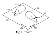
図3は、従来の多層光学フィルム300を示す。フィルム300は、個別のミクロ層302,304を含む。ミクロ層は、隣接するミクロ層間の境界面で一部の光が反射されるように異なる屈折率特性を有する。ミクロ層は、複数の境界面で反射された光が、発展的又は破壊的干渉を受けて膜に所望の反射又は透過特性を提供できるような薄さである。光を紫外線波長、可視光波長、又は近赤外線波長で反射するように設計された光学フィルムの場合、各ミクロ層は、一般に、約1μm未満の光学厚さ(即ち、物理的厚さ×屈折率)を有する。しかしながら、フィルムの外側表面における表皮層、又はミクロ層のパケットを分離する、フィルム内に配置された保護境界層などのより厚い層も含むことができる。
FIG. 3 shows a conventional multilayer
多層光学フィルム300の反射特性と透過特性は、それぞれのミクロ層の屈折率の関数である各ミクロ層は、少なくともフィルムの局所的位置で、面内の屈折率nx、nyと、フィルムの厚さ方向の軸に付随する屈折率nzとによって特徴付けることができる。これらの屈折率は、それぞれ互いに直交するx軸、y軸及びz軸に沿って偏光された光の対象材料の屈折率を表わす(図3参照)。
The reflection and transmission properties of the multilayer
実際には、屈折率は、賢明な材料選択及び加工条件によって制御される。フィルム300は、典型的には数十又は数百の2つの高分子の交互層A、Bを同時押出形成し、その後で、必要に応じて多層押出物を1つ以上の倍増ダイに通し、次に押出物を伸張又は他の方法で延伸させて最終フィルムを形成することによって作製することができる。得られたフィルムは、典型的には数十又は数百の個々のミクロ層で構成されており、その厚み及び屈折率は、可視又は近赤外などの所望のスペクトル領域において1つ以上の反射バンドをもたらすように調整されている。妥当な数の層で高い反射率を達成するために、隣接ミクロ層のX軸の方向に偏光された光の屈折率の差(Δnx)は少なくとも0.05でよい。2つの直交する偏光に高い反射率が必要な場合、隣接ミクロ層のY軸の方向に偏光された光の屈折率の差(Δny)は少なくとも0.05でよい。
In practice, the refractive index is controlled by sensible material selection and processing conditions. The
必要に応じて、Z軸方向に偏光された光の隣接ミクロ層間の屈折率差(Δnz)を調整して、斜めに入射した光のp偏光成分に望ましい反射率特性を達成することができる。説明を容易にするために、X軸は、多層光学フィルム上のいずれの対象ポイントで、Δnxの大きさが最大になるようにフィルムの平面内で向けられると考えられる。したがって、Δnyの大きさは、Δnxの大きさと等しいか又はそれより小さくてもよい(Δnxの大きさを超えない)。更に、差Δnx、Δny、Δnzの計算を始める材料層の選択は、Δnxが負にならないように決定される。換言すると、境界をなす2つの層の屈折率の差は、Δnj=n1j−n2jであり、ここで、j=x、y又はzであり、層の名称1、2は、n1x≧n2x(即ち、Δnx≧0)になるように選択される。
If necessary, the refractive index difference (Δn z ) between adjacent micro-layers of light polarized in the Z-axis direction can be adjusted to achieve desirable reflectance characteristics for the p-polarized component of obliquely incident light. . For ease of description, X-axis, at any point of interest on a multilayer optical film it is considered that the magnitude of [Delta] n x is directed within the plane of the film to maximize. Thus, the magnitude of [Delta] n y is (not exceed the size of [Delta] n x) may be the size and equal to or smaller than that of [Delta] n x. Furthermore, selection of the difference [Delta] n x, [Delta] n y, the material layer to begin the calculation of [Delta] n z is determined so [Delta] n x is not negative. In other words, the difference in refractive index between the two bordering layers is Δn j = n 1j −n 2j , where j = x, y or z and the
斜めの入射角でのp偏光の高い反射率を維持するために、Δnz≦0.5*Δnxとなるように、ミクロ層間のz屈折率の不整合Δnzを制御して、最大面内屈折率の差Δnxより実質的に小さくすることができる。より好ましくは、Δn≦0.25*Δnxである。ゼロ又はほぼゼロの大きさのz屈折率の不一致が、p偏光に対する反射率が入射角の関数として一定又はほぼ一定である界面をミクロ層の間にもたらす。更に、z屈折率の不整合Δnzを、面内屈折率の差Δnxと反対の極性を有するように、即ちΔnz<0となるように制御することができる。この条件により、s偏光の場合と同じのように、入射角が大きくなるほどp偏光の反射率が高くなる境界面が得られる。 To maintain high reflectivity of p-polarized light at an oblique angle of incidence, so that the Δn z ≦ 0.5 * Δn x, controls the mismatch [Delta] n z z-index of the microlayers, the maximum surface it can be substantially less than the difference [Delta] n x of the inner refractive index. More preferably Δn ≦ 0.25 * Δn x. A zero or nearly zero magnitude z-index mismatch results in an interface between the microlayers where the reflectivity for p-polarized light is constant or nearly constant as a function of incident angle. Furthermore, the mismatch [Delta] n z z-index, so as to have a polarity opposite to that of the difference [Delta] n x of the in-plane refractive index, i.e., can be controlled so that [Delta] n z <0. Under this condition, as in the case of s-polarized light, a boundary surface is obtained in which the reflectance of p-polarized light increases as the incident angle increases.
あるいは、多層光学フィルムは、ポリマーミクロ層の全てが本来等方性である、即ち各々の層についてnx=ny=nzであるような、より簡単な構造を有することもできる。更に、コレステリック反射偏光子及びある種のブロックコポリマーなどの既知の自己組立周期構造を、本出願の目的のための多層光学フィルムと考えることができる。左手及び右手キラル・ピッチ素子の組み合わせを使用してコレステリック・ミラーを作製することができる。 Alternatively, the multilayer optical film, all of the polymer microlayers are inherently isotropic, i.e. for each of the layers such that n x = n y = n z , may also have a simpler structure. Furthermore, known self-assembled periodic structures such as cholesteric reflective polarizers and certain block copolymers can be considered multilayer optical films for the purposes of this application. Cholesteric mirrors can be made using a combination of left-handed and right-handed chiral pitch elements.
従来の偏光フィルムに関しても、光は直交する2つの平面内で偏光されると考えることができ、この場合、光の伝搬方向と交差する光の電気ベクトルが、特定の偏光平面内にある。次に、所定の光の偏光状態を2つの異なる偏光状態(p偏光とs偏光)に分解することができる。p偏光は、光線の入射平面と所定の表面で偏光された光であり、この場合、入射平面は、局所表面法線ベクトルと光線伝搬方向すなわち伝搬ベクトルの両方を含む平面である。 With conventional polarizing films as well, light can be considered to be polarized in two orthogonal planes, where the electrical vector of light that intersects the light propagation direction is in a particular polarization plane. Next, the polarization state of a given light can be decomposed into two different polarization states (p-polarization and s-polarization). p-polarized light is light that is polarized at the plane of incidence and a given surface of the ray, where the plane of incidence is a plane that includes both the local surface normal vector and the ray propagation direction or propagation vector.
例えば、図4は、偏光子402に入射角θで入射し、それにより入射面412が形成される光線410を示す。偏光子402は、Y軸と平行な通過軸404と、X軸と平行な遮断軸406とを有する。光線410の入射面412は、遮断軸406と平行である。光線410は、入射面412内にあるp偏光成分と、入射面412と直交するs偏光成分とを有する。光線410のp偏光は、偏光子402の遮断軸406と平行であり、したがって、偏光子によって実質的に反射され、光線410のs偏光は、偏光子402の通過軸404と平行であり、少なくとも一部分が透過される。
For example, FIG. 4 shows a
更に、図4は、偏光子402の通過軸404と平行な入射面422内の偏光子402に入射する光線420を示す。したがって、光線420のp偏光は、偏光子402の通過軸404と平行であり、光線420のs偏光は、偏光子402の遮断軸406と平行である。その結果、偏光子402が、遮断軸で偏光された光に関しても全ての入射角で100%の反射率を有し、また通過軸で偏光された光に関しても全ての入射角で0%の反射率を有する完全な偏光子であると仮定すると、偏光子は、光線410のs偏光と光線420のp偏光を透過し、更に光線410のp偏光と光線420のs偏光を反射する。即ち、偏光子402は、p偏光とs偏光の組み合わせを透過する。本明細書で更に詳しく説明されるように、p偏光とs偏光の透過量と反射量は、偏光子の特性に依存する。
Further, FIG. 4 shows a
一般に、前面反射体(例えば、図2の前面反射体210)として使用する種々の非対称の反射フィルムは、低屈折率材料の面内屈折率の整合の相対的な程度を、隣接した複屈折の高屈折率材料のz軸の屈折率によって変化させることによって、提供することができる。ある実施形態では、非対称の反射フィルムの両方の面内光学軸に沿って比較的大きい面内屈折率の不整合が必要とされるが、この不整合は、互いに大きく異なり、したがって垂直入射の透過特性と反射特性が非対称になる。これは、面内屈折率が通過軸に沿って実質的に整合された従来の反射偏光フィルムと対照的である。そのようなフィルムの例は、光が垂直入射で面内軸に沿って偏光された光に関して低い反射率を有するDBEF(3M Companyから入手可能)である。
In general, various asymmetrical reflective films used as front reflectors (eg,
例えば、本開示の前面反射体に使用することができる例示的な非対称の反射フィルムは、nx1=1.82とny1=1.62の面内屈折率値と、nz1=1.50のZ軸屈折率を有する高屈折率層(即ち、最も高い屈折率を含む層)と、nx2=ny2=nz2=1.56の面内屈折率を有する等方性の低屈折率層とを有することができる。これらの屈折率を有するフィルムは、標準フィルム・テンターのような限定一軸延伸を使用してcoPEN/PETG共押出多層フィルムを使用して形成することができる。約300個の層を使用して、y−z平面と平行な偏光ベクトル(「通過」軸)を有する400〜870nmの光に関して図5に示した反射率を達成することができる。X軸に沿った屈折率の差が大きくブルースター角がないため、x−z平面と平行な偏光ベクトルを有する光の約98%が反射される。図5は、p偏光(曲線502)とs偏光(曲線504)の空気中の異なる入射角における通過軸に関する光の反射率を示す。図示したように、そのようなフィルムは、ある偏光では可視光の約29%の軸上の平均反射率を有することができ、遮断軸ではそれよりはるかに高い約98%の反射率を有することができる。 For example, exemplary asymmetric reflective films that can be used in the front reflector of the present disclosure include in-plane refractive index values of nx1 = 1.82 and ny1 = 1.62, and a Z-axis of nz1 = 1.50. A high refractive index layer having a refractive index (that is, a layer including the highest refractive index) and an isotropic low refractive index layer having an in-plane refractive index of nx2 = ny2 = nz2 = 1.56. it can. Films with these refractive indices can be formed using coPEN / PETG coextruded multilayer films using limited uniaxial stretching such as standard film tenter. About 300 layers can be used to achieve the reflectivity shown in FIG. 5 for 400-870 nm light having a polarization vector (“pass” axis) parallel to the yz plane. Since the refractive index difference along the X axis is large and there is no Brewster angle, approximately 98% of light having a polarization vector parallel to the xz plane is reflected. FIG. 5 shows the light reflectance for the pass axis at different angles of incidence in air for p-polarized light (curve 502) and s-polarized light (curve 504). As shown, such a film can have an average reflectance on the axis of about 29% of visible light for some polarized light and a much higher reflectance of about 98% on the blocking axis. Can do.
一般に、図5に示したような高屈折率の二軸複屈折材料を使用することにより、第1の(遮断)軸と平行に偏光されたほとんどの可視光成分を遮りかつ直交(通過)軸と合わされた制御量のs偏光成分とp偏光成分両方を通す非対称の反射体の設計が可能になる。この通過軸に沿ったs偏光とp偏光の相対反射率は、第2の材料の等方性屈折率n2をny1〜nz1の何からの値に変化させることによって調整することができる。 In general, by using a biaxial birefringent material with a high refractive index as shown in FIG. 5, most visible light components polarized parallel to the first (blocking) axis are blocked and orthogonal (passing) axes. It is possible to design an asymmetric reflector that passes both a controlled amount of s-polarized components and p-polarized components. The relative reflectances of the s-polarized light and the p-polarized light along the passing axis can be adjusted by changing the isotropic refractive index n2 of the second material from any value of ny1 to nz1.
前面反射体に利用される非対称の反射フィルムは、nx1>>ny1>>nz1の屈折率を有する極めて2軸複屈折性の高屈折率材料を含むことができる。これは、幾つかの材料の制約された単軸の伸張によって達成することもでき、同一材料若しくは他の材料の非対称の配向によって達成することもできる。この関係により、以下の基準を同時に満たすフィルムを設計することができる。 Asymmetric reflective film to be used in the front reflector can include the n x1 >> n y1 very biaxially birefringent properties of the high refractive index material having a refractive index of >> n z1. This can be achieved by constrained uniaxial stretching of several materials, or by asymmetric orientation of the same or other materials. This relationship makes it possible to design a film that simultaneously satisfies the following criteria.
・Δnyの値は、有効数の層で通過軸の実質的反射率(例えば、25%〜90%)を達成できるほど大きい。この制限は、本明細書で更に詳述するような低カラーフィルムに必要なスペクトル制御に関連する。ある実施形態では、これは、Δny≧約0.05であることが好ましいことがある。 The value of [Delta] n y is substantially reflectance pass axis with a layer of effective number (e.g., 25% to 90%) large enough can be achieved. This limitation is related to the spectral control required for low color films as detailed further herein. In certain embodiments, it may be preferred that Δn y ≧ about 0.05.
・Δnxの値は、遮断軸が通過軸よりかなり少ない光しか透過しないことを保証するように、Δnyよりかなり大きくてもよい。一般に、Δnx≧2Δnyであることが好ましいことがある。 The value of [Delta] n x is to ensure that the block axis light only passes through considerably less than shaft passes, may be considerably larger than [Delta] n y. In general, it may be preferred that Δn x ≧ 2Δn y.
・Δnzは、Δnxよりかなり小さくてもよく、ある実施形態では、反対符号である。これは、特に斜め入射角で、遮断軸に沿って偏光された光が漏れるのを防ぐのに役立つ。 Δn z may be significantly smaller than Δn x , and in some embodiments are opposite signs. This helps to prevent leakage of polarized light along the blocking axis, particularly at oblique incidence angles.
偏光出力を提供し通過状態の少なくとも一部の光を反射する前面反射体は、光リサイクリング・キャビティー内の光のリサイクリングを増やすことによって、1つ以上の光源を含むバックライトからの放射光の空間均一性を許容可能なレベルにすることができる。このタイプのバックライトの一部分の概略表現は、図6に示され、バックライト600は、中空の光リサイクリング・キャビティー602を形成する前面反射体610と背面反射体620を含む。キャビティー602内の光660は、前面反射体610に入射する光を表し、第1の偏光状態(a)及びそれと直交する第2の偏光状態(b)の光を含む。前面反射体610は、偏光状態(a)を有する光662の一部分を透過し、状態(a)を有する光の第2の部分664を反射し、偏光状態(b)を有する全ての光666を実質的に反射する。反射光664,666は、背面反射体620によって反射され、前面反射体610に向けられ、この場合も、状態(a)の一部分668が透過され、状態(a)の第2の部分と状態(b)の実質的に全てが反射される。偏光状態(a)及び(b)の両方の光のこの反射の結果として、キャビティー602内で光を方向670に横方向に伝えることができる。典型的なバックライトでは、偏光状態(a)の光は、第1の通過でバックライトを実質的に透過し、それによりキャビティー内で横方向に伝達される光の量が減少することがある。二次元で示されているが、本開示のバックライトは、キャビティー内の直交する両方の方向の光の横方向の伝達を提供することができ、その結果、光が実質的にキャビティーを満たし、キャビティーから放射される光の空間均一性が許容可能なものになる。
A front reflector that provides a polarized output and reflects at least some of the light in the pass state, emits light from a backlight that includes one or more light sources by increasing light recycling in the light recycling cavity. The spatial uniformity of light can be made to an acceptable level. A schematic representation of a portion of this type of backlight is shown in FIG. 6, where the
本開示の前面反射体は、許容可能な空間均一性を提供するのに役立つだけでなく、前面反射体の実施形態によっては、有効な光を例えば表示装置に角度選択的に透過させることができる。 The front reflector of the present disclosure not only helps provide acceptable spatial uniformity, but in some embodiments of the front reflector, effective light can be transmitted angle-selectively, for example, to a display device. .
一般に、前面反射体の少なくとも幾つかの実施形態は、一般に光の入射角と共に増大する反射率と、一般に入射角と共に減少する透過率を示し、ここで、反射率と透過率は、偏光された可視光といずれの入射平面に関するものでありかつ/又は有効な偏光状態の斜めの光がp偏光される平面に入射する有効な偏光状態の光に関するものである。例えば、図5と図7A、Bは、本開示の前面反射体の種々の実施形態の通過軸での入射角と反射率との関係を示す。 In general, at least some embodiments of the front reflector generally exhibit a reflectance that increases with the angle of incidence of light and a transmittance that generally decreases with the angle of incidence, where the reflectance and transmittance are polarized. It relates to visible light and any plane of incidence and / or to light in an effective polarization state where oblique light in an effective polarization state is incident on a plane that is p-polarized. For example, FIG. 5 and FIGS. 7A and B show the relationship between the angle of incidence and reflectance at the pass axis of various embodiments of the front reflector of the present disclosure.
図5は、標準モデリング法を用いてモデル化された前面反射体の一実施形態に関する通過軸反射率と空気中の可視光の入射角との関係を示す。図5に示した反射率を有する前面反射体は、標準フィルム・テンダーのような制約された一軸の配向を使用してcoPEN/PETG共押出多層フィルムを用いて形成することができる。約300個の層を使用して、図5に示した反射率は、y−z平面と平行な偏光ベクトル(即ち、通過軸)を有する400〜870nmの可視光に関して達成することができる。 FIG. 5 shows the relationship between pass axis reflectivity and incident angle of visible light in air for one embodiment of a front reflector modeled using standard modeling methods. A front reflector having the reflectivity shown in FIG. 5 can be formed using a coPEN / PETG coextruded multilayer film using a constrained uniaxial orientation such as a standard film tender. Using about 300 layers, the reflectivity shown in FIG. 5 can be achieved for 400-870 nm visible light having a polarization vector (ie, pass axis) parallel to the yz plane.
曲線502は、通過軸でのp偏光の反射率を表わし、曲線504は、通過軸でのs偏光の反射率を表わす。反射率値は、多層フィルムからの反射と空気/フィルム境界での表面反射を含む。図5で分かるように、s偏光とp偏光の両方の反射率は、入射角が増大するほど増えることになる。X軸に沿った屈折率差が大きくブルースター角がないため、x−z平面と平行な偏光ベクトル(即ち、遮断軸)を有する光の約98%が反射される。したがって、この単一フィルムは、通過軸と平行に偏光された制御量の光を透過する前面反射体を形成する複数フィルムの役割を果たすことができる。通過軸に関して計算された60度でのs偏光とp偏光の平均反射率は、約50%である。更に、遮断軸と平行な平面内で偏光された全ての光の反射率は、約99%より大きくてもよい。
一般に、図5に関して述べた非対称の反射フィルムのような高屈折率の二軸複屈折材料を使用することにより、1つの軸に平行に偏光された光成分ほとんどを遮断し、かつ直交(通過)軸と整合された、制御量のs偏光成分とp偏光成分の両方を通す非対称の反射体を設計することができる。この通過軸に沿ったs偏光とp偏光の相対反射率は、第2の材料の等方性屈折率n2をny1〜nz1の間の何らかの値に変化させることによって調整することができる。 In general, by using a high refractive index biaxial birefringent material such as the asymmetric reflective film described with respect to FIG. 5, most of the light component polarized parallel to one axis is blocked and orthogonal (passed). An asymmetric reflector that is aligned with the axis and passes both a controlled amount of the s and p polarization components can be designed. The relative reflectances of the s-polarized light and the p-polarized light along the pass axis can be adjusted by changing the isotropic refractive index n2 of the second material to some value between ny1 and nz1.
屈折率の関係、それらの数値、及び多層スタック設計は全て、ある実施形態では、一つの軸(即ち、通過軸)に沿った中間透過値と、その約10倍以下で垂直入射において他方の(遮断)軸に沿った透過値とを有する前面反射体を作製すると考えられるべきである。更に、遮断軸が、どの入射角でもあまり光を漏らさないことが好ましく、したがって、そのような実施形態は、遮断軸に関して大きなブルースター角を必要とするか又はブルースター角を必要としない。通過軸は、使用されるシステムが、直角からずらされた光の角度分布を受け入れることができる場合にブルースター角を有することができる。 The refractive index relationships, their numerical values, and the multilayer stack design are all in one embodiment an intermediate transmission value along one axis (ie, the pass axis) and the other ( It should be considered to produce a front reflector having a transmission value along the cutoff axis. Furthermore, it is preferred that the blocking axis does not leak much light at any angle of incidence, so such embodiments require a large Brewster angle or no Brewster angle with respect to the blocking axis. The pass axis can have a Brewster angle if the system used can accept an angular distribution of light shifted from a right angle.
最高の面内屈折率を有する材料として規定される「高」屈折率材料は、nx1>>ny1>>nz1の順番で2軸の高い複屈折性にすることができる。これは、幾つかの材料の制約された単軸の伸張又は同一若しくは他の材料の非対称の配向によって達成することができる。この関係により、以下の3つの基準を同時に満たすフィルムを設計することができる。 A “high” index material, defined as the material having the highest in-plane index of refraction, can be biaxially high birefringence in the order of n x1 >> n y1 >> n z1 . This can be achieved by constrained uniaxial stretching of several materials or asymmetric orientation of the same or other materials. This relationship makes it possible to design a film that simultaneously satisfies the following three criteria.
1)通過軸で偏光された可視光の反射率が少なくとも25%かつ90%未満の場合、Δnyの値は、有効数の層で通過軸に関して実質的反射率を達成できるほど大きくなければならない。実際の材料と処理システムにおいて、Δny≧約0.05が要求される。 1) If the reflectivity of visible light polarized at the pass axis is at least 25% and less than 90%, the value of Δny must be large enough to achieve a substantial reflectivity with respect to the pass axis in an effective number of layers. In actual materials and processing systems, Δn y ≧ about 0.05 is required.
2)遮断軸での光の透過が少なくなるように、Δnxの値は、Δnyより著しく大きくなければならない。一般に、Δnx≧2*Δnyであることが好ましいことがある。更に、Δnzが、Δnxより小さく逆符号のものであることが好ましいことがある。 2) As the transmission of light is reduced in block axis, the value of [Delta] n x has to be significantly greater than the [Delta] n y. In general, there may be preferred a Δn x ≧ 2 * Δn y. Further, [Delta] n z is, it may be preferable that smaller than the opposite sign [Delta] n x.
本明細書に示したように、前面反射体は、s偏光とp偏光両方の反射率を入射角の関数として高めることができる。この効果は、プリズムBEFフィルム、又は一般に当業界で使用される利得拡散フィルムの効果と類似の、バックライト表示装置における角度「利得」を生成する。前面反射体により、斜角での高い反射率は、バックライト内でより高い透過可能性を有する低角度の光線に変換される斜光線をリサイクルする。この方法で、多くの光が、高角度でのときよりほぼ垂直入射で光リサイクリング・キャビティーから放射される。 As shown herein, the front reflector can increase the reflectivity of both s-polarized light and p-polarized light as a function of incident angle. This effect produces an angular “gain” in the backlight display, similar to the effect of prism BEF film, or gain diffusion film commonly used in the industry. Due to the front reflector, the high reflectivity at the oblique angle recycles the oblique light which is converted into a low angle light with a higher transmission possibility in the backlight. In this way, more light is emitted from the light recycling cavity at approximately normal incidence than at high angles.
典型的な液晶表示パネルでは、下側吸収偏光子(即ち、図1の下側吸収偏光子156)の通過軸は、液晶表示パネル上で水平方向に向けられることが多い。この構成の場合、p偏光は水平面に入射し、s偏光は垂直面に入射する。そのようなパネルの横方向の視角は、一般に、垂直視角より大幅に広いことが望ましいが、それらの相対値を制御することが望ましいことがある。したがって、s偏光とp偏光の反射率及びその後の角度利得の相対量は、制御されることが望ましいパラメータである。一般に、下側吸収偏光子の通過軸は、観察者に対するいずれの適切な配向、例えば、水平や垂直などに対するいかなる角度にも向けることができる。
In a typical liquid crystal display panel, the pass axis of the lower absorbing polarizer (ie, the lower absorbing
図7Aは、標準モデリング法を使用してモデル化された前面反射体の別の実施形態に関する通過軸反射率と空気中の光の入射角との関係を示す。図7Aに示した反射率を有する前面反射体は、標準フィルム・テンターと同じような制約された一軸の配向を使用して、coPEN/PMMA共押出多層フィルムを用いて形成することができる。約300の層を使用して、図7Aに示した反射率は、y−z平面に平行な偏光ベクトル(即ち、通過軸)を有する400〜870nmの光に関して達成することができる。coPENのミクロ層の屈折率は、nx1=1.82、ny1=1.61、及びnz1=1.52である。また、PMMAのミクロ層の屈折率は、nx2=ny2=nz2=1.49である。曲線706は、通過軸でのp偏光の反射率を表わし、曲線708は、通過軸でのs偏光の反射率を表わす。曲線710は、遮断軸でのp偏光とs偏光両方の反射率を表わす。反射率値は、多層フィルムからの反射と空気/フィルム境界での表面反射を含む。s偏光では、この実施形態の材料及び屈折率を多層スタック設計で使用して、角度利得又はコリメーションを作製することができるが、この前面反射体の通過軸によって透過されるp偏光では使用できない。
FIG. 7A shows the relationship between pass axis reflectivity and incident angle of light in air for another embodiment of a front reflector modeled using standard modeling methods. A front reflector having the reflectivity shown in FIG. 7A can be formed with a coPEN / PMMA coextruded multilayer film using a constrained uniaxial orientation similar to a standard film tenter. Using about 300 layers, the reflectivity shown in FIG. 7A can be achieved for 400-870 nm light with a polarization vector (ie, pass axis) parallel to the yz plane. The refractive index of the microlayer of coPEN is nx1 = 1.82, ny1 = 1.61, and nz1 = 1.52. The refractive index of the microlayer of PMMA is nx2 = ny2 = nz2 = 1.49.
図7Aに示したように、屈折率n2は、nz1より僅かに小さく、p偏光の通過軸の反射率は、入射角が増大するほど減少する。水平通過軸を有する液晶表示パネルでのこのようなフィルムの場合、キャビティーから垂直入射以外のどちらかの側により多くの光が出ることになり、即ち、パネルは、垂直入射以外の側から見たときに、明るくなる。利得拡散フィルム又は垂直方向の溝を有するBEFフィルムを追加して、法線(垂直)観察方向により多くの光を導くことができる。あるいは、低屈折率材料をnz1より高い屈折率を有するように変更することができる。垂直面内のキャビティーから出る光は、主に、s偏光である。図7Aに示したように、s偏光の反射率は、入射角の関数として実質的に増大することになる。したがって、この前面反射体は、垂直面に入射する高角度光の多くをリサイクルし、それにより、垂直方向の実質的な角度利得が生成されることになる。 As shown in FIG. 7A, the refractive index n2 is slightly smaller than nz1, and the reflectivity of the pass axis of p-polarized light decreases as the incident angle increases. In the case of such a film in a liquid crystal display panel having a horizontal pass axis, more light will be emitted from the cavity to either side other than normal incidence, i.e. the panel is viewed from the side other than normal incidence. When it gets brighter. A gain diffusing film or a BEF film with vertical grooves can be added to guide more light in the normal (vertical) viewing direction. Alternatively, the low refractive index material can be modified to have a refractive index higher than nz1. The light exiting from the cavity in the vertical plane is mainly s-polarized light. As shown in FIG. 7A, the reflectivity of s-polarized light will substantially increase as a function of incident angle. Thus, this front reflector will recycle much of the high angle light incident on the vertical surface, thereby creating a substantial vertical angular gain.
要約すると、図5と図7Aを参照すると、低屈折率材料の屈折率値を、高屈折率材料のny1〜nz1の値で選択することによって、s偏光とp偏光の反射率の相対的強度を角度の関数として制御することができる。このようにして、各方向のバックライト・キャビティーからの偏光の角度利得又はコリメーションを制御することができる。屈折率ny2をnz1より低くすることができるが、ny2をそのように低くすることは、通過軸に沿ってブルースター角が生成され高い入射角度でp偏光入射が漏れることになるので望ましくないことがある。そのような設計は、負の角度利得を作り出す。ny2をny1より大きくすると同じ結果となり得る。更に、ny2をny1より大きくすると、反射体の遮断軸での反射率が低下し、それにより、望ましくない偏光状態を有する光の漏れを防ぐためにフィルムに付加的な層が必要になる可能性がある。 In summary, referring to FIGS. 5 and 7A, the relative intensities of the s-polarized and p-polarized reflectances are selected by selecting the refractive index value of the low refractive index material with the values of ny1 to nz1 of the high refractive index material. Can be controlled as a function of angle. In this way, the angular gain or collimation of the polarization from the backlight cavity in each direction can be controlled. Refractive index ny2 can be lower than nz1, but making ny2 so low is undesirable because it creates a Brewster angle along the pass axis and leaks p-polarized light at high incidence angles. There is. Such a design creates a negative angular gain. The same result can be obtained by making ny2 larger than ny1. Furthermore, if ny2 is greater than ny1, the reflectivity at the reflector's cutoff axis is reduced, which may require an additional layer on the film to prevent leakage of light having an undesirable polarization state. is there.
また、高屈折率材料と低屈折率材料の両方からなる複屈折の場合、s偏光とp偏光の角度利得の相対量を調整することができる。低屈折率層用のそのような材料を、高屈折率層と同じか又は逆の複屈折を有するように選択することができ、ny2とnz2の相対値を、s偏光とp偏光の反射率の相対的な大きさを決定するように選択することができる。 Further, in the case of birefringence composed of both a high refractive index material and a low refractive index material, the relative amount of the angular gain of s-polarized light and p-polarized light can be adjusted. Such a material for the low refractive index layer can be selected to have the same or opposite birefringence as the high refractive index layer, and the relative values of ny2 and nz2 are the reflectance of s-polarized light and p-polarized light. Can be selected to determine the relative magnitude of.
例えば、図7Bは、標準モデリング法を使用してモデル化された前面反射体の別の実施形態の通過軸反射率と空気中の光の入射角の関係を示す。図7Bに示した反射率を有する前面反射体は、高屈折率材料のcoPEN及び低屈折率材料のシンジオタクチック・ポリスチレン(sPS)又はポリビニル・ナフタリン(PVN)又は他の適切な材料を使用して形成することができる。これらの材料は、標準フィルム・テンターのような制約された一軸の配向を使用して共押出多層フィルムを形成することが可能である。約275の層を使用して、図7Bに示した反射率は、y−z平面と平行な偏光ベクトル(即ち、通過軸)を有する400〜870nmの光に関して達成することができる。coPENのミクロ層の屈折率は、nx1=1.82、ny1=1.61、及びnz1=1.50である。また、sPS(又は他の適切な材料)のミクロ層の屈折率は、nx2=1.52、ny2=1.57、及びnz2=1.65である。曲線712は、通過軸でのp偏光の反射率を表わし、曲線714は、通過軸でのs偏光の反射率を表わす。反射率値は、多層フィルムからの反射と、空気/フィルム境界での表面反射を含む。
For example, FIG. 7B shows the relationship between the pass axis reflectivity and the incident angle of light in air for another embodiment of a front reflector modeled using standard modeling methods. The front reflector having the reflectivity shown in FIG. 7B uses high refractive index material coPEN and low refractive index material syndiotactic polystyrene (sPS) or polyvinyl naphthalene (PVN) or other suitable material. Can be formed. These materials are capable of forming coextruded multilayer films using a constrained uniaxial orientation, such as a standard film tenter. Using about 275 layers, the reflectivity shown in FIG. 7B can be achieved for 400-870 nm light having a polarization vector (ie, pass axis) parallel to the yz plane. The refractive index of the microlayer of coPEN is nx1 = 1.82, ny1 = 1.61, and nz1 = 1.50. Also, the refractive index of the microlayer of sPS (or other suitable material) is nx2 = 1.52, ny2 = 1.57, and nz2 = 1.65.
一般に、両方の材料が複屈折性のとき、低屈折率材料が高屈折率材料と反対の複屈折性を有する場合は、Δnyの値を減少(又は維持)させながらΔnzを増大させることができる。低屈折率材料が、高屈折率材料と同じ符号の複屈折性を有する場合は、Δnyの値を維持又は減少させながらΔnzを減少させることができる。図7Bに示したように、p偏光(曲線712)は、s偏光(曲線714)よりも大きな割合で入射角の関数として増加する。その結果、p偏光は、s偏光よりはるかに大きな角度利得又はコリメーションを示す。 In general, when both materials are birefringent, if the low index material has the opposite birefringence as the high index material, Δnz can be increased while decreasing (or maintaining) the value of Δny. . When the low refractive index material has the same birefringence as the high refractive index material, Δnz can be decreased while maintaining or decreasing the value of Δny. As shown in FIG. 7B, p-polarized light (curve 712) increases as a function of incident angle at a greater rate than s-polarized light (curve 714). As a result, p-polarized light exhibits much greater angular gain or collimation than s-polarized light.
一般に、プリズム輝度強化フィルムは、軸上の光を反射し軸を外れた光を屈折させることにより光の部分的なコリメータの役割をする。例えば、図28は、プリズム輝度強化フィルム2800の一部分の概略断面図である。フィルム2800に、平滑面2802と構造化面2804を有する。構造化面2804は、複数の三角柱2806を有する。光線2810は、グレージング角(即ち、法線に対して90度に近い角度)で平滑面2802に入射し、屈折される。光線2810は、構造化面2804に達すると再び屈折される。光線2812は、光線2810よりも平滑面2802の法線に近い角度で平滑面2802に近づく。また、光線2812は、平滑面2802と構造化面2804の両方を通るときに、屈折される。更に、光線2814は、光線2838より平滑面2802の法線に更に近い角度で平滑面2802に入射し、構造化面2804によって2回内部全反射される。
In general, the prism brightness enhancement film acts as a partial collimator of light by reflecting light on the axis and refracting off-axis light. For example, FIG. 28 is a schematic cross-sectional view of a portion of the prism
図示したように、比較的大きい角度で輝度強化フィルム2800上に入射する光線(即ち、光線2810)は、プリズム面によって法線の方に屈折される傾向があり、一方、比較的小さい角度で入射する光線(即ち、光線2814)は、(プリズム面でTIRによって)入射方向の方に後方反射される傾向がある。このプロセスによって、リサイクリング・キャビティーなどの角度混合光源(angle-mixed source)からの光線は、構造化面2804を介して直角の方に収束される。プリズム面でTIRプロセスからキャビティー内に後方反射された光は、典型的な光リサイクリング・キャビティー内の背面反射体によって反射され得る。背面反射体が、少なくとも部分的に拡散する反射性である場合は、その反射光は、再び角度混合され、リサイクリング・プロセスにより、直角観察者円錐のまわりの輝度は、輝度強化フィルム2800なしの観察者円錐内への輝度よりも高くなることがある。
As shown, light rays that are incident on the
利得立方体を使用して種々の前面反射体の角度性能を測定することができる。例えば、「複合拡散板及びそれを使用したダイレクトリット液晶ディスプレイ(COMPOSITE DIFFUSER PLATES AND DIRECT-LIT LIQUID CRYSTAL DISPLAYS USING SAME)」と題する米国特許公開第2006/0082700号(ゲルセン(Gehlsen)他)を参照されたい。以下の前面反射体の実施形態を測定するために使用される利得立方体は、側面の厚さ1.59cm(5/8インチ)で上部の厚さ0.635cm(1/4インチ)のTeflon(登録商標)(PTFE)の壁で作製された12.7cm(5インチ)Teflon(登録商標)立方体を含んでいた。この立方体は、アルミニウム底板を備えたTeflon(登録商標)を有していた。この板に、サーマル・テープを使用して回路基板上のLEDを取り付けた。2xTIPS(説明の例を参照)を使用して、LED用に穴が空けられた底をライニングした。このリサイクリング・キャビティーの構成によって、(バックプレーン全体にわたって)空間的に均一に拡散する照明と、適度に反射性で高い拡散性を持つリサイクリング・キャビティーが得られ、それにより、種々の前面反射体の実施形態のリサイクリングバックライト・キャビティーの輝度変化を測定するために使用できる単純なリサイクリング・キャビティー・デバイスが提供される。 The gain cube can be used to measure the angular performance of various front reflectors. For example, see US Patent Publication No. 2006/0082700 (Gehlsen et al.) Entitled "COMPOSITE DIFFUSER PLATES AND DIRECT-LIQUID CRYSTAL DISPLAYS USING SAME". I want. The gain cube used to measure the following front reflector embodiment is a Teflon with a side thickness of 1.59 cm (5/8 inch) and a top thickness of 0.635 cm (1/4 inch). It contained a 12.7 cm (5 inch) Teflon® cube made of (PTFE) walls. The cube had Teflon® with an aluminum bottom plate. The LED on the circuit board was attached to this board using thermal tape. 2xTIPS (see example description) was used to line the bottom perforated for the LED. This recycling cavity configuration provides a spatially and evenly diffused illumination (over the entire backplane) and a reasonably reflective and highly diffusive recycling cavity, which allows a variety of A simple recycling cavity device is provided that can be used to measure the brightness change of the recycling backlight cavity of the front reflector embodiment.
以下の実施形態では、利得立方体の上にSanritz、モデルHLC2−5618S吸収偏光子が配置され、ドイツ国カールスルーエ(Karlsruhe)のautronic−MELCHERS社から入手可能なConoscope(登録商標)光学測定システムを使用してコノスコープ輝度を測定した。利得立方体の上に吸収偏光子を配置することによって基準線測定を実行した。次に、利得立方体の上に種々の前面反射体を配置し、前面反射体の上に吸収偏光子を配置した。そして、この構成で行われたコノスコープ輝度の測定により、単純なリサイクリングバックライト輝度の変化が、観察者の(測定)観測角の関数になることが実証された。種々の前面反射体実施形態に関する測定輝度値が示され、アジマス角が0°と90°の場合に法線からグレージング角までの角度範囲で輝度をプロットした。アジマス角が0°の場合、吸収偏光子通過軸と整合された光はs偏光され、アジマス角が90°の場合、吸収偏光子通過軸と整合された光はp偏光される。 In the following embodiment, a Sanritz, model HLC2-5618S absorbing polarizer is placed on top of the gain cube, and a Conoscope® optical measurement system available from autonic-MELCHERS, Karlsruhe, Germany is used. The conoscope brightness was measured. Baseline measurements were performed by placing an absorbing polarizer on the gain cube. Next, various front reflectors were disposed on the gain cube, and an absorbing polarizer was disposed on the front reflector. And conoscopic luminance measurements performed in this configuration demonstrated that a simple recycling backlight luminance change is a function of the observer's (measured) observation angle. The measured luminance values for various front reflector embodiments are shown and the luminance is plotted in the angular range from the normal to the glazing angle for azimuth angles of 0 ° and 90 °. When the azimuth angle is 0 °, the light aligned with the absorbing polarizer passage axis is s-polarized, and when the azimuth angle is 90 °, the light aligned with the absorption polarizer passage axis is p-polarized.
図29は、単一のBEFシートの輝度と極角の関係を示すグラフである。曲線2902及び2904はそれぞれ、0°と90°でのBEFを表わし、曲線2906及び2908はそれぞれ、BEFなしの0°と90°での吸収偏光子を表わす。直角円錐への輝度は、1.605倍になり、輝度強化は、90°アジマス面に沿った(溝の方向の)広い角度範囲と、0°アジマス面に沿った(溝に垂直方向の)狭い角度範囲に広がった。更に、高角度での輝度は、出力面に吸収偏光子だけを有する利得立方体の出力より大幅に低下した。
FIG. 29 is a graph showing the relationship between the luminance and polar angle of a single BEF sheet.
図30は、交差した2枚のBEFの輝度と極角の関係を示すグラフである。曲線3002及び3004はそれぞれ、0°と90°で交差BEFを表わし、曲線3006及び3008はそれぞれ、交差BEFなしの0°と90°における吸収偏光子を表わす。直角円錐への輝度は、2.6倍になり、輝度強化は、90°アジマス面と0°アジマス面の両方に沿ってかなり狭くなる。
FIG. 30 is a graph showing the relationship between the luminance and polar angle of two crossed BEFs.
図31は、上に重なった吸収偏光子の通過軸と整合された通過軸を有するAPF(実施例の記載で更に説明)の輝度と極角の関係を示すグラフである。曲線3102及び3104はそれぞれ、0°と90°におけるAPFを表わし、曲線3106及び3108はそれぞれ、APFなしの0°と90°における吸収偏光子を表す。APF前面反射体は、直角円錐への輝度を1.72倍にし、輝度強化は、90°アジマス面では高角度まで極めて広いままであり、0°アジマスに沿って狭くなる。
FIG. 31 is a graph showing the relationship between the brightness and polar angle of an APF (further described in the description of the example) having a pass axis aligned with the pass axis of the overlying absorbing polarizer.
図32は、上に重なった吸収偏光子の通過軸と整合された通過軸を有するDBEFの輝度と極角の関係を示すグラフである。曲線3202及び3204はそれぞれ、0°と90°におけるDBEFを表わし、曲線3206及び3208はそれぞれ、DBEFなしの0°と90°における吸収偏光子を表わす。DBEF前面反射体は、直角円錐への輝度を1.66倍にし、APF前面反射体と同様に、輝度強化、90°アジマス面の場合は大きな角度まで極めて広いままであり、0°アジマスに沿って狭くなった。
FIG. 32 is a graph showing the relationship between the luminance and polar angle of DBEF having a pass axis aligned with the pass axis of the absorbing polarizer overlaid.
図33は、上に重なった吸収偏光子の通過軸と整合された通過軸を有する3xARF(説明の実施例を参照)の輝度と極角の関係を表すグラフである。曲線3302及び3304はそれぞれ、0°と90°における3xARFを表わし、曲線3306及び3308はそれぞれ、3xARFなしの0°と90°における吸収偏光子を表わす。3xARF前面反射体は、直角円錐への輝度を1.84倍に増大させ、輝度強化は、90°アジマス面と0°アジマス面の両方で角度が高くなるほど狭くなる。この直角円錐輝度の増大は、標準の反射偏光子フィルムAPF及びDBEFより十分に上回り、これは、APFとDBEFのもの(表1参照)と比べて3xARF前面反射体の増大した半球反射率によって引き起こされた可能性がある。この直角観察者円錐輝度の増大は、3xARFフィルムからの追加リサイクリングにより、リサイクリング及び角度混合キャビティー光線が前面反射体を透過する可能性が高まるので、軸上の透過が増加した場合でも起こる。更に、出力面を介した高角度輝度の低下は、液晶表示パネル・コントラスト比を要求レベルに維持するために追加のプリズム又は屈折構成要素が不要な場合があるので、有利になり得る。
FIG. 33 is a graph showing the relationship between the luminance and polar angle of 3xARF (see the example in the description) having a pass axis aligned with the pass axis of the absorbing polarizer overlaid.
図34は、上に重なった吸収偏光子の通過軸と整合された通過軸を有するARF−86(ビーズコートARF−84と同一構造。詳細は実施例を参照)の輝度と極角の関係を示すグラフである。曲線3402及び3404はそれぞれ、0°と90°におけるARF−86を表わし、曲線3406及び3408はそれぞれ、ARF−86なしの0°と90°における吸収偏光子を表わす。図34では、前面反射体が、ARF−86と吸収偏光子両方の通過軸に沿って偏光された光に関して極めて反射性が高いので、直角円錐内の輝度増加は本質的にゼロである。半球反射率が92.1%でも、直角観察者円錐の輝度は、吸収偏光子だけに対して変化しない。
FIG. 34 shows the relationship between the luminance and polar angle of ARF-86 (same structure as bead coat ARF-84; see the example for details) having a pass axis that is aligned with the pass axis of the overlying absorbing polarizer. It is a graph to show.
図35は、ビーズコート上面を有し、上に重なった吸収偏光子の通過軸と整合された通過軸を有するARF−86(説明の実施例参照)の輝度と極角の関係を示すグラフである。曲線3502及び3504はそれぞれ、0°と90°におけるARF−86を表わし、曲線3506及び3508はARF−86なしのそれぞれ、0°と90°における吸収偏光子を表わす。したがって、屈折効果によって下から表面構造に遭遇する角度混合光をコリメートにする傾向がある。同時に、ビーズコート面は、ARF−86フィルムから出て、出力面を介してキャビティーから出るときに、ビーズコート面を通る偏光線の偏光をある程度ランダム化する傾向がある。この効果により、p偏光輝度は、ビーズコートのないARF−86と比較して、角度が大きくなるほど低下する。
FIG. 35 is a graph showing the relationship between the luminance and polar angle of ARF-86 (see Example of Description) having a bead-coated top surface and a pass axis aligned with the pass axis of the overlying absorbing polarizer. is there.
図2に戻ると、前面反射体210は、所望の反射特性と透過特性を提供する1つ以上のフィルム又は層を含むことができる。ある実施形態では、前面反射体は、2つ以上のフィルムを含むことができる。例えば、図8Aは、前面反射体800の一部分の概略断面図である。反射体800は、第2のフィルム804の近くに位置する第1のフィルム802を有する。フィルム802、804は、離間されてもよいし、互いに接触してもよい。あるいは、フィルム802、804は、いずれの適切な技術を使用して貼り付けられてもよい。例えば、フィルム802、804は、いずれの接着層806を使用して積層されてもよい。層806には、いずれの適切な接着剤(例えば、感圧接着剤(3M Optically Clear Adhesivesなど)及び紫外線硬化接着剤(UVX−4856など)を使用することができる。ある実施形態では、接着層806は、屈折率整合流体に置き換えられてもよく、フィルム802、804は、当該技術分野で既知のいずれの適切な技術を使用して接触状態で保持されてもよい。
Returning to FIG. 2, the
フィルム802、804は、前面反射体に関して本明細書で述べたいずれの適切なフィルムも含むことができる。フィルム802、804は、類似の光学特性を有することができ、あるいは、フィルム802、804は、異なる光学特性を提供する異なる構造でもよい。一つの例示的な実施形態では、フィルム802は、ある平面内に通過軸を有する本明細書に記載したような非対称の反射フィルムを含むことができ、フィルム804は、第1のフィルム802の通過軸と平行でない第2の平面内に通過軸を有する第2の非対称の反射フィルムを含むことが可能である。この非平行関係は、2つの通過軸平面の間でいかなる適切な角度を形成することができる。ある実施形態では、通過軸平面はほぼ直角であることが可能である。そのような関係は、前面反射体800の通過軸に高い反射率を提供することになる。
更に、例えば、フィルム802は、非対称の反射フィルムを含んでもよく、フィルム804は、BEFなどのプリズム輝度強化フィルムを含んでもよい。ある実施形態では、BEFは、非対称のフィルムの平行面と直角の平面内でBEFが透過光をコリメートにするように非対称の反射フィルムに対して向けられてもよい。あるいは、他の実施形態では、BEFは、BEFが非対称の反射フィルムの平行化面内で透過光をコリメートにするように向けられてもよい。
Further, for example, the
他の実施形態では、フィルム802は、本明細書に記載されたいずれの適切なフィルム(例えば、非対称の反射フィルム)も含むことができ、フィルム804は、いずれの適切な基板層であり得る。基板には、例えば、ポリカーボネート、アクリル、PET、例えば「繊維強化光学フィルム(FIBER REINFORCED OPTICAL FILMS)」と題する米国特許公開第2006/0257678号(ベンソン(Benson)他)、「強化反射偏光子フィルム(REINFORCED REFLECTIVE POLARIZER FILMS)」と題する米国特許出願第11/323,726号(ライト(Wright)他)及び「強化反射偏光子フィルム(REINFORCED REFLECTIVE POLARIZER FILMS)」と題する米国特許出願第11/322,324号(オーダカーク(Ouderkirk)他)に記載された繊維強化光学フィルムなどのいずれの適切な材料が挙げられる。
In other embodiments,
前面反射体800は、2つのフィルム802、804を含むように示されているが、前面反射体800は、3つ以上のフィルムを含んでもよい。例えば、3つの反射偏光子層(DBEFやAPFなど)を使用して3層前面反射体を作製することが可能でもよい。3つの層が、第2層の偏光軸が第1層の偏光軸に対して45°になりかつ第3層の偏光軸が第1層の偏光軸に対して90°になるように配列された場合、得られる前面反射体は、垂直入射光の約75%を反射する。層間の他の回転角を使用して、異なるレベルの反射を達成することができる。
Although the
また、ほぼ直交する通過軸を有する2つの反射偏光子の間の複屈折(偏光回転)層又は散乱層が、前面反射体として使用される制御された程度の反射率を有する反射フィルムを作製することができる。2つの反射偏光子の通過軸は、整合されてもよく、斜めにされてもよいし、直交されてもよい。反射偏光子の間の層は、複屈折板、プリズムフィルム、拡散体、又は第1の反射偏光子を通過する偏光を回転又はスクランブル(scrambling)させる特性を有する他の光学フィルムであってもよい。また、反射偏光子の間の層は、支持板や拡散体などの2つ以上のフィルムの組み合わせでもよい。層は、互いに離されてもよいし、積層や他の貼り合わせ方法によって貼り付けられてもよい。 In addition, a birefringent (polarization rotation) layer or scattering layer between two reflective polarizers having substantially orthogonal pass axes is used to produce a reflective film having a controlled degree of reflectance used as a front reflector. be able to. The pass axes of the two reflective polarizers may be aligned, tilted, or orthogonal. The layer between the reflective polarizers may be a birefringent plate, a prism film, a diffuser, or other optical film having the property of rotating or scrambling the polarized light passing through the first reflective polarizer. . The layer between the reflective polarizers may be a combination of two or more films such as a support plate and a diffuser. The layers may be separated from each other, or may be attached by lamination or other bonding methods.
本開示の前面反射体は、また、反射体の1つ以上の面内又は面上に位置する光学素子を含んでもよい。例えば、図8Bは、前面反射体810の別の実施形態の一部分の概略断面図である。反射体810は、第1の主面814と第2の主面816を有するフィルム812を含む。フィルム812は、本明細書で前面反射体に関して説明されたいずれの適切なフィルム又は層を含むこともできる。複数の光学素子818は、第1の主面814上又は第1の主面814内に位置決めされる。光学素子は、第1の主面814上でのみ配置されているように示されているが、第2の主面816上に配置されてもよいし、第1及び第2の主面814,816の両方の上に配置されてもよい。フィルム812上又はフィルム812内に、いずれの適切な光学素子(例えば、ミクロスフェア、プリズム、コーナーキューブ、レンズ等)を配置することができる。光学素子は、屈折素子、回折素子、拡散素子などでよい。他の実施形態では、光学素子818は、光学素子812の配置により、フィルム812に入射する光又はフィルム812から出る光を拡散させることができる。
The front reflector of the present disclosure may also include an optical element located in or on one or more planes of the reflector. For example, FIG. 8B is a schematic cross-sectional view of a portion of another embodiment of
光学素子818は、フィルム812の主面上に配置されてもよく、フィルム812の主面に少なくとも部分的に埋め込まれてもよい。更に、フィルム810は、いずれの適切な技術(例えば、ビーズコートESRを製造するための本明細書に記載された技術)を使用して製造することができる。
The
光学素子818は、また、フィルム810の近くに位置するカバー層又は基板上に配置され得る。例えば、図8Cは、前面反射体820の別の実施形態の一部分の概略断面図である。反射体820は、フィルム822と、フィルム822の近くに配置された利得拡散体824を含む。フィルム820は、本明細書で前面反射体に関して説明されたいずれのフィルム及び/又は層も含むことができる。利得拡散体824は、第1の主面828と第2の主面830を有する基板826と、基板826の第2の主面830上又は第2の主面830内に配置された複数の光学素子832を含む。例えば図8Bの光学素子818などのいずれの適切な光学素子832を使用することができる。基板826は、いずれの適切な光透過基板を含むことができる。
The
図8Cに示した実施形態では、利得拡散体824の第1の主面828が、フィルム822の近くに配置される。拡散体824は、フィルム822から離間されるか、フィルム822と接触するか、フィルム822に貼り付けるように、フィルム822の近くに配置することができる。いずれの適切な技術を使用(例えば、光学接着剤の使用)して、拡散体824をフィルム822に貼り付けることができる。拡散体824にはいずれの適切な利得の拡散体を使用することができる。ある実施形態では、光学素子832は、基板826の第1の主面828上に、素子832が基板826と偏光フィルム822の間になるように配置されてもよい。
In the embodiment shown in FIG. 8C, the first
図2に戻ると、前面反射体210は支持層に貼り付けられてもよい。支持層は、いずれの適切な材料(例えば、ポリカーボネート、アクリル、PETなど)を含むことができる。ある実施形態では、前面反射体210は、例えば「繊維強化光学フィルム(FIBER REINFORCED OPTICAL FILMS)」と題する米国特許公開第2006/0257678号(ベンソン(Benson)他)、「強化反射偏光子フィルム(REINFORCED REFLECTIVE POLARIZER FILMS)」と題する米国特許出願第11/323,726号(ライト(Wright)他)、及び「強化反射偏光子フィルム(REINFORCED REFLECTIVE POLARIZER FILMS)」と題する米国特許出願第11/322,324号(オーダカーク(Ouderkirk)他)に記載されたような繊維強化光学フィルムによって支持されてもよい。更に、前面反射体210は、いずれの適切な技術を使用して支持層に取り付けられ得る。ある実施形態では、前面反射体210は、光学接着剤を使用して支持層に接着されてもよい。前面反射体210と支持体層は、いずれの適切な技術、例えば、「光透過複合フィルムフレーム(OPTICALLY TRANSMISSIVE COMPOSITE FILM FRAME)」と題する米国特許出願第60/947,776号(サンホルスト(Thunhorst)他)に記載された技術を使用してバックライトに取り付けられ得る。
Returning to FIG. 2, the
ある実施形態では、前面反射体210は、液晶パネルに取り付けられ得る。例えば、前面反射体は、パネル板154に取り付けられた図1の下側吸収偏光子158に取り付けられ得る。
In some embodiments, the
本明細書で述べるように、前面反射体210は、部分的に反射性及び部分的に透過性の前面反射体を提供するいずれの適切なフィルム及び/又は層を含むことができる。ある実施形態では、前面反射体210は、例えば「高分子ファイバを含む反射偏光子(REFLECTIVE POLARIZERS CONTAINING POLYMER FIBERS)」と題する米国特許公開第2006/0193577号(オーダカーク(Ouderkirk)他)、「多層偏光ファイバ及びそれを使用した偏光子(MULTILAYER POLARIZING FIBERS AND POLARIZERS USING SAME)」と題する米国特許出願第11/468,746号(オーダカーク(Ouderkirk)他)、及び「高分子ファイバ偏光子(POLYMER FIBER POLARIZERS)」と題する米国特許出願第11/468,740号(ブルーム(Bluem)他)に記載された1つ以上のファイバ偏光フィルムを含むことができる。
As described herein,
前面反射体210に使用することができる他の例示的なフィルムには、コレステリック偏光フィルム、複屈折パイル・オブ・プレーツ・フィルム、及び複屈折ポリマ・ブレンド(例えば、3M Companyから入手可能なDRPF)がある。本開示の非対称の反射フィルムは、いずれの適切な技術を使用して製造することができる。例えば、「多層光学フィルムを製造するための装置(APPARATUS FOR MAKING MULTILAYER OPTICAL FILMS)」と題する米国特許第6,783,349号(ネービン(Neavin)他)を参照されたい。例えば、図9A〜図9Bは、本開示の非対称の反射フィルムの製造方法の一実施形態を示す。適切な異なる光学的性質を有するように選択された材料900及び902が、選択材料の溶融温度及び/又はガラスの遷移温度を超えるまで加熱され、多層供給ブロック904に供給される。一般的に、溶融と上記供給は、各材料ごとに押出成形機を使用して達成される。例えば、材料900を押出成形機901に供給する一方で、材料902を押出成形機903に供給することができる。供給ブロック904から出力するのは、多層のフローストリーム905である。層倍増機構(layer multiplier)906は、多層流ストリームを分割し、次に1つのストリームを第2のストリームの上に向け直して「積み重ね」て、押出成形された層の数を増加させる。非対称の倍増機構は、スタック全体にわたる層厚さの偏りを導入する押出成形機器と共に使用するとき、多層フィルムが、光の可視スペクトルの所望部分に対応する層対を有し、かつ所望の層厚さ勾配を提供することを目的として、層厚さの分布を拡大させることができる。必要に応じて、表皮層911が、樹脂908(表皮層用樹脂)を表皮層供給ブロック910に供給することによって、フィルムに導入されてもよい。
Other exemplary films that can be used for the
多層供給ブロックは、フィルム押出形成ダイ912に供給する。適切な供給ブロックは、例えば米国特許第3,773,882号(シュレンク(Schrenk))と同第3,884,606号(シュレンク(Schrenk))に記載されている。例えば、押出成形温度は、約295C°でよく、供給速度は、各材料ごとに約10〜150kg/時である。ある実施形態では、フィルムが供給ブロックとダイを通るときに、フィルムの上側及び下側面に表皮層911を流すようにすることが好ましいことがある。これらの層は、壁の近くに見られる大きな応力勾配を分散させる働きをし、光学層の押出形成がより滑らかになる。各表皮層の典型的な押出成形速度は、2〜50kg/時(総処理量の1〜40%)になる。表皮材料は、光学層と同一の1つの材料、又は異なる材料であることが可能である。ダイから放出される押出物は、一般に、溶融形態である。
The multi-layer feed block feeds to the film extrusion die 912. Suitable supply blocks are described, for example, in U.S. Pat. Nos. 3,773,882 (Schrenk) and 3,884,606 (Schrenk). For example, the extrusion temperature may be about 295 C ° and the feed rate is about 10-150 kg / hour for each material. In certain embodiments, it may be preferred to have the
押出物は、ピン止めワイヤ914の後で回転する鋳造ホイール916上で冷却される。ピン止めワイヤは、押出物を鋳造ホイールにピン止めする。広い角度範囲にわたる透明フィルムを達成するために、鋳造ホイールを低速で動作させることによってフィルムを厚くし、反射帯域をより長波長の方に移すことができる。フィルムは、所望の光学特性と機械特性により決められた比率で伸張により延伸される。縦方向の伸張は、引張ローラ918によって行うことができる。横方向の伸張は、テンターオーブン920内で行うことができる。望むならば、フィルムは同時に2軸で延伸され得る。約3〜4対1の伸張比率が好ましいことがあるが、所定のフィルムには1対1ほどの小さい比率と6対1ほどの大きい比率が適切な場合もある。伸張温度は、使用される複屈折高分子のタイプに依存するが、一般には、そのガラス転移温度を超える2°〜33℃(5°〜60°F)が適切な範囲になる。フィルムは、一般に、フィルムの結晶度を最大にしその収縮を小さくするために、テンターオーブンの最後の2つのゾーン922内で熱設定される。テンター内でフィルムを破損させずにできるだけ高い熱設定温度を使用することにより、加熱エンボス工程での収縮が減少する。また、テンター・レールの幅を約1〜4%小さくすることで、フィルム収縮が減少する。フィルムがヒートセットされない場合は、熱収縮特性が最大になり、これは、幾つかの安全なパッケージング用途で望ましい場合がある。フィルムは、巻取ロール924に収集することができる。
The extrudate is cooled on a
幾つかの用途では、多層フィルムの光学層に3つ以上の異なる高分子を使用することが望ましいことがある。そのような場合、樹脂ストリーム900及び902と類似の手段を使用して追加の樹脂ストリームを供給することができる。3つ以上の層タイプを分散させるために供給ブロック904と類似の適切な供給ブロックを使用することができる。
In some applications, it may be desirable to use more than two different polymers in the optical layer of the multilayer film. In such cases, additional resin streams can be provided using means similar to
図9Bは、ハウジング928に取り囲まれた供給ブロック904の一実施形態の概略斜視図を示す。ハウジング928内には、傾斜板930が存在する。傾斜板930には、第1の流路932と第2の流路934の少なくとも2つの流路がある。流路は、傾斜板930と供給管板940の組み合わせによって範囲が決められる。
FIG. 9B shows a schematic perspective view of one embodiment of a
傾斜板930内で、各流路は、その断面が、例えば、円、正方形、正三角形等の対称の中心軸を有するように機械加工される。機械加工を容易にするために、正方形断面の流路が使用されることが好ましい。各流路に沿って、断面積は一定のままでもよく変化してもよい。この変化は、面積の増加でも減少でもよく、断面が減少する場合は、一般に、「テーパ」と呼ばれる。流路の断面積の変化は、多層光学フィルムの層厚さ分布に影響を及ぼす適切な気圧勾配を提供するように設計されてもよい。したがって、傾斜板は、様々なタイプの多層フィルム構造のために変更することができる。
Within the
流路の断面積が、一定のままのとき、層の厚さと層数の関係を示すプロットは非線形的に減少する。所定の高分子流では、層数に依存して層の厚さが線形的に減少する少なくとも1つの断面テーパ状プロファイルが存在し、このプロファイルが好ましいことがある。テーパ状プロファイルは、当該の高分子に関する信頼性の高い流動学データと当該技術分野で既知の高分子流シミューレーション・ソフトウェアを使用する当業者によって求めることができ、場合に応じて計算されなければならない。 When the cross-sectional area of the channel remains constant, the plot showing the relationship between the layer thickness and the number of layers decreases nonlinearly. For a given polymer flow, there is at least one cross-sectional taper profile in which the layer thickness decreases linearly depending on the number of layers, and this profile may be preferred. Tapered profiles can be determined by those skilled in the art using reliable rheological data on the polymer of interest and polymer flow simulation software known in the art and must be calculated accordingly. I must.
図9Bを再び参照すると、供給ブロック904は、更に、流路932及び934とそれぞれ流体が連通する第1組の導管942と第2組の導管944とを有する供給管板940を収容する。本明細書で使用されるとき、「導管」は、「サイトチャネル管」とも呼ばれる。導管942と944は軸方向棒状ヒータ946に隣接し、導管内の樹脂の流れに熱を供給する。必要に応じて、軸方向棒状ヒータの長さに沿ったゾーン内で温度を変化させることができる。各導管は、それ自体のそれぞれのスロット・ダイ956に供給し、スロット・ダイ956は拡張部分とスロット部分を有する。拡張部分は、一般に、供給管板940内に存在する。必要に応じて、スロット部分は、スロット板950内にあってもよい。本明細書で使用されるとき、用語「スロット・ダイ」は、「層スロット」と同意語である。第1組の導管942は、第2組の導管944と交互に配置されて、交互層が形成される。
Referring again to FIG. 9B, the
使用時、例えば、樹脂Aと樹脂Bが、流路932及び934に直接送られる。溶融流(melt stream)Aと溶融流Bが、傾斜板930内の流路を下り、各溶融流は導管によって抜き取られる。導管942及び944は、交互に配置されるので、例えばABABABのように交互層を形成し始める。各導管は、実際の層を形成し始めるためにそれ自体のスロット・ダイを有する。スロット・ダイから出る溶融流は、複数の交互層を含む。溶融流は、圧縮部分(図示せず)に送り込まれ、そこで層が圧縮され、また横方向に均一に広げられる。保護境界層(PBL)として知られる特殊な厚い層が、光学多層スタックに使用される溶融流のいずれかから供給ブロック壁の最も近くに供給されてもよい。PBLは、また、供給ブロック後の別個の注入流によって供給され得る。PBLは、より薄い光学層を、壁応力の影響とその結果生じる可能性のある流れの不安定性から保護する働きをする。
In use, for example, the resin A and the resin B are directly sent to the
ある実施形態では、本開示の非対称の反射フィルムを、倍増機構(例えば、倍増機構906)を使用せずに製造することができる。倍増機構は、多数の光学層の生成を大幅に単純化するが、各パケットごとに同一でない各合成層パケットに歪みを与えることがある。この理由のため、供給ブロック内で生成された層の層厚さプロファイルの調整は、各パケットごとに同じではなく、即ち、スペクトル分断のない均一で滑らかなスペクトルを生成するために全てのパケットを同時に最適化できるとは限らない。したがって、最適なプロファイルと低透過率のカラー色反射体は、倍増機構を使用して製造された複数パケットのフィルムを使用して作製するのは難しいことがある。供給ブロック内で直接生成された単一パケット内の層の数が、十分な反射率を提供しない場合は、2つ以上のそのようなフィルムが貼り付けられ、反射率を高めることができる。 In certain embodiments, an asymmetric reflective film of the present disclosure can be manufactured without using a doubling mechanism (eg, doubling mechanism 906). The doubling mechanism greatly simplifies the generation of multiple optical layers, but may distort each composite layer packet that is not identical for each packet. For this reason, the adjustment of the layer thickness profile of the layers generated in the supply block is not the same for each packet, i.e. all packets are generated in order to generate a uniform and smooth spectrum without spectral fragmentation. It is not always possible to optimize at the same time. Thus, an optimal profile and low transmittance color color reflector may be difficult to fabricate using a multi-packet film manufactured using a doubling mechanism. If the number of layers in a single packet generated directly in the supply block does not provide sufficient reflectivity, two or more such films can be applied to increase reflectivity.
図9Aの方法から倍増機構が除去されたときは、軸方向の棒状ヒータ946を使用して、例えば米国特許第6,783,349号に更に詳しく記載されたように共押出高分子層の層厚さ値を制御することができる。そのような軸方向の棒状ヒータは、供給ブロック内で一定温度を維持するためと、約40℃までの温度勾配を作り出すための両方に利用することができる。ある実施形態では、軸方向の棒状ヒータは、供給ブロックの口径内に置かれ層平面と垂直な方向に向けられ、好ましくは各サイドチャネル管がスロット・ダイに供給する箇所を通る想像線の極めて近くに置かれる。より好ましくは、第1の高分子と第2の高分子とを同時押出成形する場合、軸方向の棒状ヒータ用の口径は、各サイドチャネル管がスロット・ダイを供給する箇所を通り、かつ第1の高分子を支持するサイドチャネル管と第2の高分子を支持するサイドチャネル管から等距離の想像線の近くに配置される。更に、軸方向の棒状ヒータは、その長さに沿った電気抵抗の変化によって、又はマルチゾーン制御によって、又は当該技術分野で既知の他の手段によってその長さに沿った温度勾配又は多様な離散的な温度を提供できるタイプのものであることが好ましい。このような軸方向の棒状ヒータは、「鋭角帯域端を有する光学フィルム(OPTICAL FILM WITH SHARPENED BANDEDGE)」と題する米国特許第6,157,490号(ホイートリー(Wheatley)他)と「カラーシフトフィルム(COLOR SHIFTING FILM)」と題する米国特許出願第6,531,230号(ウェーバー(Weber)他)に記載されているように、反射バンドの位置とプロファイルを制御する際に特に重要な層の厚さと勾配層の厚さ分布を制御することができる。
When the doubling mechanism is removed from the method of FIG. 9A, an
供給ブロック904は、フィルム・スタック内の全ての層が軸方向の棒状ヒータ946によって直接制御されるように構成される。層の厚さプロファイルは、工程中に、いかなる適切な厚さ測定技術(例えば、原子間力顕微鏡法、透過型電子顕微鏡法、走査型電子顕微鏡法)を使用することによって監視することができる。層の厚さプロファイルは、いずれの適切な技術を使用して光学的にモデル化することができ、次に軸方向の棒状ヒータを、測定された層のプロファイルと所望の層のプロファイルの差に基づいて調整することができる。
一般にAFMほど正確でないが、光学スペクトルを積分(波長スペクトルに対する−Log(1−R)の積分)することによって簡単に層プロファイルを評価することができる。これは、層の厚さプロファイルが、層数に対して単調増加又は減少する場合に、層の厚さプロファイルの微分から反射体のスペクトル形状を求めることができるという一般原理から可能である。 Although generally not as accurate as AFM, the layer profile can be easily evaluated by integrating the optical spectrum (the integration of -Log (1-R) with respect to the wavelength spectrum). This is possible from the general principle that the spectral shape of the reflector can be determined from the differentiation of the layer thickness profile when the layer thickness profile monotonically increases or decreases with the number of layers.
層の厚さプロファイルを制御する基本プロセスは、ターゲット層の厚さのプロファイルと測定した層のプロファイルの差に基づく軸方向の棒状ゾーン出力設定の調整を含む。最初に、所定の供給ブロック・ゾーン内の層の厚さ値を調整するために必要とされる軸方向の棒状ヒータ出力の増加を、そのヒータ・ゾーン内で生じた層の厚さ変化の1ナノメートル当たりに入力された熱のワット数に対して較正することができる。スペクトルの細かい制御は、275層に対して24個の軸方向の棒状ゾーンを使用して可能である。一旦較正されると、所定のターゲット・プロファイルと測定プロファイルの必要な電力調整を一度に計算することができる。この手順は、2つのプロファイルが収束するまで繰り返される。 The basic process of controlling the layer thickness profile involves adjusting the axial rod zone power setting based on the difference between the target layer thickness profile and the measured layer profile. Initially, the increase in axial rod heater power required to adjust the layer thickness value in a given feed block zone is one of the layer thickness changes that occurred in that heater zone. It can be calibrated against the wattage of heat input per nanometer. Fine spectral control is possible using 24 axial rod zones for 275 layers. Once calibrated, the required power adjustments for a given target profile and measurement profile can be calculated at once. This procedure is repeated until the two profiles converge.
例えば、275層のフィルムは、前述の技術により、nx1=1.82、ny1=1.61、nz=1.50の屈折率を有するcoPENと、全ての方向に屈折率n2=1.57を有するポリカーボネートとPCTGの混合物とを使用して作製された。通過軸上の入射角60°のp偏光の測定透過スペクトルを、図10に曲線1002として示す。また、遮断軸の透過を曲線1004として示す。遮断軸スペクトルと通過軸スペクトルとは共に極めて広い帯域で比較的一定の透過率を有することに注意されたい。
For example, a 275-layer film has coPEN having a refractive index of nx1 = 1.82, ny1 = 1.61, nz = 1.50 and a refractive index n2 = 1.57 in all directions by the above-described technique. And a mixture of PCTG and PCTG. The measured transmission spectrum of p-polarized light at an incident angle of 60 ° on the pass axis is shown as a
図2に戻ると、バックライト200は、また、前面反射体210と共に中空の光リサイクリング・キャビティー202を形成する背面反射体220を有する。背面反射体220は、極めて反射性であることが好ましい。例えば、背面反射体220は、光源によって放射された可視光に関して、いずれの偏光の可視光の少なくとも90%、95%、98%、99%又はそれ以上の軸上の平均反射率を有することができる。そのような反射率値は、また、高リサイクリング・キャビティー内の損失量を減少させることができる。そのような反射率値は、半球内に反射される全ての可視光を含み、即ち、そのような値は、鏡面反射と拡散反射の両方を含む。
Returning to FIG. 2, the
背面反射体220は、空間的に均一又はパターン化されているのにかかわらず、大部分は鏡面反射体、拡散反射体、又は鏡面反射体/拡散反射体の組み合わせであり得る。ある実施形態では、背面反射体220は、本明細書で更に詳しく説明されるような半鏡面反射体であり得る。また、「有益な設計特徴を有するリサイクリングバックライト(RECYCLING BACKLIGHTS WITH BENEFICIAL DESIGN CHARACTERISTICS)」と題するPCT特許出願第XXXX/XXXXXX明細書(代理人整理番号63032WO003)と「表示装置に適したバックライト(BACKLIGHT SUITABLE FOR DISPLAY DEVICES)」と題する米国特許出願第11/467,326号(マー(Ma)他)を参照されたい。ある実施形態では、背面反射体220は堅い高反射率コーティングを有する金属基材、又は支持基材に積層された高反射率フィルムから作製され得る。適切な高反射率材料には、3M Companyから入手可能なVikuiti(登録商標)強化鏡面反射体(ESR)多層高分子フィルム、厚さ10.16μm(0.4ミル)のイソオクチルアクリレート・アクリル感圧接着剤を使用して硫酸バリウム混合ポリエチレンテレフタレート・フィルム(50.8μm(厚さ2mil))をVikuiti(登録商標)ESRフィルムに貼り付けることによって作製され、本明細書で「EDR II」フィルムと呼ばれる合成ラミネート・フィルム、Toray Industries,Inc.から入手可能なE−60シリーズLumirror(登録商標)ポリエステル・フィルム、W.L.Gore & Associates,Incから入手可能なものなどの多孔性ポリテトラフルオロエチレン(PTFE)フィルム、Alanod Aluminum−Veredlung GmbH & Co.から入手可能なMiro(登録商標)アルマイト・フィルム(Miro(登録商標)2フィルムを含む)、Furukawa Electric Co.,Ltd.から入手可能なMCPET高反射発泡シート材、Mitsui Chemicalsから入手可能なWhite Refstar(登録商標)フィルムとMTフィルム、及び2xTIPS(説明の実施例を参照)が挙げられる。
Regardless of whether the
背面反射体220は、実質的に平らで滑らかでもよいし、光の散乱又は混合を強化するように関連付けられた構造化面を備えてもよい。そのような構造化面は、(a)背面反射体220の表面上に与えられてもよいし、(b)表面に付着された透明被覆上に与えられてもよい。前者の場合、高反射フィルムが、構造化面が予め形成された基板に貼り付けられてもよいし、高反射フィルムが、平坦基板(3M Companyから入手可能なVikuiti(登録商標)(DESRM:Durable Enhanced Specular Reflector-Metal)反射体と同様の薄い金属板など)に貼り付けられ、その後で打ち抜き操作などにより構造化面が形成されてもよい。後者の場合、構造化面を有する透明フィルムを平らな反射面に貼り付けてもよいし、透明フィルムを反射体に貼り付け、その後で透明フィルムの上に構造化面を設けてもよい。
The
ダイレクトリット構造を含む実施形態(例えば、図16のバックライト1600)では、背面反射体は、光源が取り付けられた、連続する単一(かつ切れ目の無い)層でもよいし、個別部分で不連続的に構成されてもよいし、光源が通ることができる孤立した穴を有する限り、別の形の連続層で不連続的に構成されてもよい。例えば、反射材料ストリップが、光源列が取り付けられた基板に貼り付けられ、各ストリップが、ある光源列から別の光源列まで延在するのに十分な幅を有しかつバックライトの出力領域の両方の境界の間にわたるのに十分な寸法を有してもよい。
In embodiments that include a direct lit structure (eg, the
また、バックライト200は、バックライト200の外側境界の少なくとも一部分に沿って配置された1つ以上の側面反射体250を有することができ、上記外側境界の部分は、光損失を減少させかつリサイクリング効率を改善するために、高反射率の垂直壁が好ましくは立ち並ぶか別の方法で提供されてもよい。これらの反射体を形成するために、背面反射体220に使用されているものと同じ反射材料を使用してもよく、異なる反射材料を使用してもよい。ある実施形態では、側面反射体250と背面反射体220は、単一の材料シートから形成することができる。
The
側面反射体250は垂直でもよく、あるいは1つ以上の反射体が傾けられてもよい。また、側面反射体250の反射材料は、背面反射体220に使用される材料と同じでも異なってもよい。側面反射体250には、鏡面材料、半鏡面材料、拡散材料を使用することができる。所望の反射プロファイルを達成するために、側面反射体250の上又は側面反射体の隣りに屈折構造体を使用することができる。隔壁材料と傾斜とは、輝度プロファイルを調整するように選択することができる。
The
光源230を概略的に示す。ほとんどの場合、これらの光源230は小型の発光ダイオード(LED)である。この点で、「LED」は、可視、紫外線、又は赤外線にかかわらず、発光するダイオードを指す。それは、従来型又は超放射型の種類にかかわらず、「LED」として販売されている非干渉性封入又は密閉型半導体デバイスを含む。LEDが紫外線などの非可視光線を発する場合、及びLEDが可視光線を発するある特定の場合、LEDは、蛍光体を含むようにパッケージ化(あるいは遠隔配置された蛍光体を照射)することができ、短波長の光を長波長の可視光線に変え、特定の場合には白色光を発する装置を提供する。「LEDダイ」は、最も基本的な形態、即ち半導体加工手順によって製造される個々の構成要素又はチップの形態のLEDである。構成要素又はチップは、デバイスに電圧を加えるための電力の適用に好適な電気接点を含むことができる。構成要素又はチップの個々の層及びその他の機能的要素は、通常、ウェハスケールで形成された後、完成したウェハは個々の小片部に切られて、多数のLEDダイとなることができる。パッケージ化されたLEDの詳細については、前面発光及び側面発光のLEDを含めて、本明細書で更に説明する。
A
多色光源は、白色光の生成に使用されるかどうかにかかわらず、バックライトの出力領域で色及び輝度の均一性に異なる効果を与えるように、バックライトで多数の形態を取ることができる。ある手法では、複数のLEDダイ(例えば、赤、緑、及び青色を発光するダイ)がリード線フレーム又はその他の基材に全て互いに隣接して実装され、1つのパッケージを形成するように1つの内包材で一緒に封入される。この場合、パッケージにはレンズ要素が1つだけ含まれていてもよい。このような光源は、いずれか1つの個別の色、又は同時にすべての色を発光するように制御可能である。別の手法では、1パッケージにつき1つのLEDダイと1色の発光色を提供する、個別にパッケージ化されたLEDを、所定のリサイクリング・キャビティーに一緒にまとめて配置してもよく、この集合体には青/黄又は赤/緑/青などの異なる色を発光するパッケージ化LEDの組み合わせが含まれる。また別の手法では、このような個別にパッケージ化された多色LEDを1つ以上のライン、配列、又はその他のパターンに配置してもよい。 Regardless of whether the multicolor light source is used to generate white light, it can take many forms in the backlight to have different effects on color and brightness uniformity in the output area of the backlight. . In one approach, multiple LED dies (eg, red, green, and blue light emitting dies) are all mounted adjacent to each other on a lead frame or other substrate to form a single package. Enclosed together with inner packaging material. In this case, the package may include only one lens element. Such a light source can be controlled to emit any one individual color or all colors simultaneously. In another approach, individually packaged LEDs that provide one LED die and one emission color per package may be placed together in a predetermined recycling cavity. The aggregate includes a combination of packaged LEDs that emit different colors such as blue / yellow or red / green / blue. In another approach, such individually packaged multicolor LEDs may be arranged in one or more lines, arrays, or other patterns.
LED効率は、温度に依存し、一般に温度の上昇と共に低下する。この効率の低下は、LEDのタイプにより異なることがある。例えば、赤色LEDは、青色LED又は緑色LEDよりかなり大きい効率低下を示す。熱の影響を受けやすいLEDが熱的に分離して、それらのLEDが、ヒートシンク上でより低いワット密度を有するように及び/又は他のLEDからの熱伝達を受けないようにする場合に、本開示の種々の実施形態を使用してこの影響を軽減することができる。従来のバックライトでは、1色のLEDの集合体を配置すると、色の均一性が低下した。本開示では、例えば赤色LEDの集合体の色を緑色及び青色LEDとよく混合して白を作ることができる。光センサとフィードバック・システムを使用して、LEDからの光の輝度及び/又は光のカラーを検出し制御することができる。例えば、個別のLED又はLEDの集合体の近くにセンサを配置して、出力を監視し、白色点又は色温度を制御し、維持し、又は調整するためにフィードバックを提供することができる。混合光をサンプリングするための中空キャビティー内の縁に沿って1つ以上のセンサを配置することが有益なことがある。幾つかの例では、観察環境(例えば、表示装置が配置された部屋)で表示装置の外部の周囲光を検出するセンサを提供することが有益なことがある。そのような場合、制御論理を使用して、周囲の観察条件に基づいて表示光源出力を適切に調整することができる。多くのタイプのセンサは、テキサス州プラノ(Plano)のTexas Advanced Optoelectronic Solutionsから入手可能な光−周波数又は光−電圧センサなどの多くのタイプのセンサを使用することができる。更に、熱センサを使用して、LEDの出力を監視し制御することができる。これらの技術は全て、動作状態に基づいてまた時間の経過と共に劣化する構成要素の補償に基づいて調整するために使用することができる。制御システムにフィードバック信号を供給するために動的コントラスト又はフィールド・シーケンシャル・システムにセンサを使用することができる。 LED efficiency is temperature dependent and generally decreases with increasing temperature. This decrease in efficiency may vary depending on the type of LED. For example, red LEDs exhibit significantly greater efficiency degradation than blue or green LEDs. When thermally sensitive LEDs are thermally isolated so that they have a lower watt density on the heat sink and / or are not subject to heat transfer from other LEDs, Various embodiments of the present disclosure can be used to mitigate this effect. In the conventional backlight, when an assembly of LEDs of one color is arranged, the color uniformity is lowered. In the present disclosure, for example, the color of an assembly of red LEDs can be mixed well with green and blue LEDs to make white. A light sensor and feedback system can be used to detect and control the brightness and / or color of light from the LED. For example, sensors can be placed near individual LEDs or collections of LEDs to monitor the output and provide feedback to control, maintain, or adjust the white point or color temperature. It may be beneficial to place one or more sensors along the edge in the hollow cavity for sampling the mixed light. In some examples, it may be beneficial to provide a sensor that detects ambient light outside the display device in an observation environment (eg, a room in which the display device is located). In such a case, control logic can be used to appropriately adjust the display light source output based on the surrounding viewing conditions. Many types of sensors can use many types of sensors such as light-frequency or light-voltage sensors available from Texas Advanced Optoelectronic Solutions of Plano, Texas. Furthermore, a thermal sensor can be used to monitor and control the LED output. All of these techniques can be used to adjust based on operating conditions and compensation for components that degrade over time. Sensors can be used in dynamic contrast or field sequential systems to provide feedback signals to the control system.
望ましい場合には、開示するバックライトの光源として、別個のLED光源の代わりに、又はLED光源に追加して、線形の冷陰極蛍光ランプ(CCFL)又は熱陰極蛍光ランプ(HCFL)などの別の可視光線発光体を使用してもよい。更に、例えば冷白色と温白色を含み(CCFL/LED)、異なるスペクトルを放射するCCFL/HCFLなどの複合システムを使用することができる。発光体の組み合わせは、幅広く異なってもよく、LEDとCCFL、及び例えば複数のCCFL、異なる色の複数のCCFL、及びLEDとCCFLなどの多数を含むことが可能である。 If desired, another light source such as a linear cold cathode fluorescent lamp (CCFL) or a hot cathode fluorescent lamp (HCFL) can be used instead of or in addition to a separate LED light source as the disclosed backlight source. A visible light emitter may be used. In addition, complex systems such as CCFL / HCFL, including, for example, cold white and warm white (CCFL / LED) and emitting different spectra can be used. The combinations of light emitters can vary widely and can include LEDs and CCFLs, and multiples such as, for example, multiple CCFLs, multiple CCFLs of different colors, and LEDs and CCFLs.
例えば、幾つかの用途では、個別の光源の列を、長い円筒形CCFLのような異なる光源と置き換えるか、又は長さに沿って光を放射し離れた能動素子(LEDダイやハロゲン電球等)に結合された線形面発光導光体と置き換え、また同様に他の光源列と置き換えることが望ましいことがある。このような線状表面発光導光体の例は、米国特許第5,845,038号(ランディン(Lundin)他)及び同6,367,941号(リー(Lea)他)に開示されている。また、ファイバ結合レーザ・ダイオードや他の半導体発光体も既知であり、そのような場合、光ファイバ導波路の出力端は、開示されたリサイクリング・キャビティー内の場所又は他の状況ではバックライトの出力領域の後の場所に対する光源であると考えることができる。電球やLEDダイなどの活性成分から受け取った光を発する、レンズ、屈折体、狭い導光体などの小さな発光領域を有する他の受身の光学構成要素についても、同じことが言える。このような受身の構成要素の一例は、側面発光パッケージ化LEDの成型内包体又はレンズである。 For example, in some applications, individual light source rows are replaced with different light sources, such as long cylindrical CCFLs, or active elements that emit light away along their length (such as LED dies and halogen bulbs). It may be desirable to replace the linear surface-emitting light guide coupled to and to other light source arrays as well. Examples of such linear surface emitting light guides are disclosed in US Pat. Nos. 5,845,038 (Lundin et al.) And 6,367,941 (Lea et al.). . Fiber-coupled laser diodes and other semiconductor light emitters are also known, in which case the output end of the fiber optic waveguide is located in the disclosed recycling cavity or in other situations a backlight. Can be considered as a light source for a location after the output region. The same is true for other passive optical components having small light emitting areas such as lenses, refractive bodies, narrow light guides, etc. that emit light received from active components such as bulbs and LED dies. An example of such a passive component is a molded inclusion or lens of a side-emitting packaged LED.
1つ以上の光源には、例えば、Luxeon(登録商標)LED(カルフォルニア州サンノゼのLumileds社から入手可能)、又は「くさび形光学素子を有するLEDパッケージ(LED PACKAGE WITH WEDGE-SHAPED OPTICAL ELEMENT)」と題する米国特許出願第11/381,324号(レーザデイル(Leatherdale)他)と「集束光学素子を有するLEDパッケージ(LED PACKAGE WITH CONVERGING OPTICAL ELEMENT)」と題する米国特許出願第11/381,293号(ルー(Lu)他)に記載されたLEDなどのいずれの適切な側面発光LEDを使用することができる。本明細書に記載した様々な実施形態に他の放射パターンが望ましいことがある。例えば、「くさび形光学素子を有するLEDパッケージ(LED PACKAGE WITH WEDGE-SHAPED OPTICAL ELEMENT)」と題する米国特許公開第2007/0257270号(ルー(Lu)他)を参照されたい。 One or more light sources include, for example, Luxeon® LEDs (available from Lumileds, San Jose, Calif.) Or “LED PACKAGE WITH WEDGE-SHAPED OPTICAL ELEMENT” No. 11 / 381,324 entitled “Laserdale et al.” And US patent application Ser. No. 11 / 381,293 entitled “LED PACKAGE WITH CONVERGING OPTICAL ELEMENT” Any suitable side-emitting LED can be used, such as those described in (Lu) et al.). Other radiation patterns may be desirable for the various embodiments described herein. For example, see US Patent Publication No. 2007/0257270 (Lu et al.) Entitled "LED PACKAGE WITH WEDGE-SHAPED OPTICAL ELEMENT".
バックライトが表示パネル(例えば、図1のパネル150)と組み合わせで使用されるある実施形態では、バックライト200は、白色光を連続的に放射し、液晶パネルは、カラー・フィルタ・マトリクスと組み合わされて、多色画素のグループ(黄/青(YB)の画素、赤/緑/青(RGB)の画素、赤/緑/青/白(RGBW)の画素、赤/黄/緑/青(RYGB)の画素、赤/黄/緑/シアン/青(RYGCB)の画素等)が形成され、その結果、表示画像は多色性になる。あるいは、カラー・シーケンシャル技術(color sequential technique)を使用して多色画像を表示することができ、この技術は、液晶パネルを白色光で連続的に後ろから照明し、液晶パネル内のグループの多色画素を変調して色を生成する代わりに、バックライト200内の個別に色付けされた光源(例えば、赤、オレンジ、琥珀、黄色、緑、シアン、青(紺青を含む)、及び以上の述べた色などの組み合わせの白から選択された)を変調して、バックライトが、空間的に均一な有色光出力を高速に繰り返し連続的(例えば、赤、次に緑、次に青など)に点滅させるものである。次に、この色変調バックライトは、(カラー・フィルタ・マトリクスのない)1つの画素配列しかないディスプレイ・モジュールと組み合わされ、この画素配列は、変調が観察者の視覚システム内で時間的に色混合されるのに十分に高速であるという条件で、バックライトと同期して変調されて、画素配列全体にわたってあらゆる達成可能な色(バックライトに光源が使用される場合)が生成される。フィールド・シーケンシャル・ディスプレイとしても知られるカラー・シーケンシャル・ディスプレイの例は、米国特許第5,337,068号(ステワート(Stewart)他)と同第6,762,743号(ヨシハラ(Yoshihara)他)に記載されている。場合によっては、単色のみのディスプレイを提供することが望ましいこともある。そのような場合、バックライト200は、1つの可視波長又は色で主に放射するフィルタ又は特定の光源を含むことができる。
In some embodiments where a backlight is used in combination with a display panel (eg,
ある実施形態では、光源は、1つ以上の偏光源を含むことができる。そのような実施形態では、偏光源の偏光軸が、前面反射体の通過軸と実質的に平行になるように向けられることが好ましい場合があり、あるいは、光源偏光軸が前面反射体の通過軸と実質的に垂直であることが好ましい場合がある。他の実施形態では、偏光軸は、前面反射体の通過軸に対していずれの適切な角度をなすことができる。 In certain embodiments, the light source can include one or more polarization sources. In such embodiments, it may be preferred that the polarization axis of the polarization source be oriented so that it is substantially parallel to the pass axis of the front reflector, or the source polarization axis is the pass axis of the front reflector. It may be preferable to be substantially vertical. In other embodiments, the polarization axis can be at any suitable angle with respect to the pass axis of the front reflector.
ある実施形態(例えば、図16に示された実施形態のようなダイレクトリット・バックライト)では、光源は、背面反射体上に配置されてもよく、あるいは、光源は、背面反射体から離間されてもよい。他の実施形態では、光源は、例えば、共有及び同時係属の米国特許出願第11/018,608号(代理人整理番号60116US002)、同第11/018,605号(代理人整理番号60159US002)、同第11/018,961号(代理人整理番号60390US002)、及び同第10/858,539号(代理人整理番号59334US002)に記載されたような背面反射体上に配置されるか又はその背面反射体に取り付けられる光源を含んでもよい。 In some embodiments (eg, a direct lit backlight such as the embodiment shown in FIG. 16), the light source may be located on the back reflector, or the light source is spaced from the back reflector. May be. In other embodiments, the light source is, for example, a shared and co-pending U.S. Patent Application No. 11 / 018,608 (Attorney Docket No. 60116US002), No. 11 / 018,605 (Attorney Docket No. 60159US002), No. 11 / 018,961 (Representative reference number 60390US002) and 10 / 858,539 (Representative reference number 59334US002) as described on or behind the back reflector A light source attached to the reflector may be included.
光源230は、いずれの適切な配列で配置されてもよい。更に、光源230は、様々な波長又は色の光を放射する光源を含むことができる。例えば、光源は、第1の波長の照明光を放射する第1の光源と、第2の波長の照明光を放射する第2の光源を含むことがある。第1の波長は、第2の波長と同じでもよいし、異なってもよい。光源230は、また、第3の波長の光を放射する第3の光源を含んでもよい。例えば、「有色LED光源を効率的に利用した白色バックライトなど(WHITE LIGHT BACKLIGHTS AND THE LIKE WITH EFFICIENT UTILIZATION OF COLORED LED SOURCES)」と題するPCT特許出願第XXXX/XXXXXX号(代理人整理番号63033WO004)を参照されたい。ある実施形態では、種々の光源230は、混合されたときに、表示パネルや他のデバイスに白色照明光を提供する光を生成することが可能である。他の実施形態では、光源230はそれぞれ白色光を出力することが可能である。
The
更に、ある実施形態では、放射光を少なくとも部分的にコリメートにする光源が好ましいことがある。そのような光源は、開示されたバックライトの中空の光リサイクリング・キャビティー内に所望の出力を提供するためのレンズ、抽出器、成形封入材、又光学素子の組み合わせを含むことができる。更に、本開示のバックライトは、リサイクリング・キャビティー内に横断面(バックライトの出力領域と平行な横断面)に近い伝搬方向に最初に注入された光、例えば半値全幅(FWHM)で0〜90度、0〜60度、0〜30度、0〜15度、又は0〜10度以下の最大角度幅(横断面に関する)を有する注入ビームを部分的に平行化又は制限する注入光学素子を含むことができる。適切な注入器形状には、くさび、放物線、複合放物線などがある。 Furthermore, in some embodiments, a light source that at least partially collimates the emitted light may be preferred. Such light sources can include a combination of lenses, extractors, molded encapsulants, and optical elements to provide the desired output within the hollow light recycling cavity of the disclosed backlight. In addition, the backlight of the present disclosure has light initially injected in the propagation direction near the cross-section (cross-section parallel to the output region of the backlight) into the recycling cavity, eg, 0 at full width at half maximum (FWHM). Injection optics for partially collimating or limiting an injection beam having a maximum angular width (with respect to the cross section) of -90 degrees, 0-60 degrees, 0-30 degrees, 0-15 degrees, or 0-10 degrees or less Can be included. Suitable injector shapes include wedges, parabolas, compound parabolas and the like.
一般に、1つ以上の光源230によってキャビティー202内に放射された光のFWHM値を制御して所望のコリメーションを提供することができる。FWHMのいかなる適切な値を提供するいかなる適切な技術を使用することができる。更に、注入光の方向を制御して所望の透過特性を提供することができる。例えば、1つ以上の光源からの光を、横断面に対していずれの適切な角度でキャビティーに導くことができる。ある実施形態では、注入光を背面反射体220の方向に導くことができる。
In general, the FWHM value of light emitted into the
本開示のある実施形態では、中空の光リサイクリング・キャビティー内である程度の拡散が行われることが好ましいことがある。そのような拡散は、キャビティー内でより大きい角度の光の混合を実現することができ、それにより、キャビティー内で光を拡散し出力面を介してキャビティーから外に導かれる光の均一性を高めるのに役立つ。換言すると、リサイクリング光学キャビティーは、キャビティーに鏡面特性と拡散特性を平衡させる構成要素を含み、この構成要素は、キャビティー内の十分な横方向の光の伝達又は混合を提供するのに十分な鏡面性を有するが、狭い範囲の伝搬角度の光しかキャビティーに注入されないときでも、キャビティー内の定常状態の光伝搬の角度分布を実質的に均一化するのに十分な拡散率も有する。更に、キャビティー内のリサイクリングの結果、入射光線の偏光状態に対する反射光偏光がある程度ランダムにならなければならない。これにより、有効でない偏光をリサイクリングによって有効な偏光に変換することができる機構が可能になる。拡散は、前面反射体及び背面反射体の一方又は両方、側面反射体、又は本明細書において更に詳しく説明されるような前面反射体と背面反射体の間に位置する1つ以上の層によって提供することができる。 In certain embodiments of the present disclosure, it may be preferable to have some diffusion within the hollow light recycling cavity. Such diffusion can achieve a larger angle of mixing of light within the cavity, thereby diffusing the light within the cavity and uniforming the light directed out of the cavity through the output surface. Helps to increase sex. In other words, the recycling optical cavity includes a component that balances the specular and diffusive properties in the cavity, which component provides sufficient lateral light transmission or mixing within the cavity. Although it has sufficient specularity, it also has sufficient diffusivity to substantially uniformize the angular distribution of steady-state light propagation within the cavity, even when light with a narrow range of propagation angles is injected into the cavity. Have. Furthermore, as a result of recycling in the cavity, the reflected light polarization relative to the polarization state of the incident light must be somewhat random. This allows a mechanism that can convert ineffective polarized light into effective polarized light by recycling. Diffuse is provided by one or both of the front and back reflectors, the side reflectors, or one or more layers located between the front and back reflectors as described in more detail herein. can do.
ある実施形態では、キャビティー内に提供された拡散は、半鏡面拡散を含むことができる。本明細書で使用されるとき、用語「半鏡面反射体」は、逆方向散乱光より多くの順方向散乱光を実質的に反射する鏡面反射体を指す。同様に、用語「半鏡面拡散体」は、実質的に大部分の入射光線に関して入射光線の法線成分を逆方向に向けず、即ち、光が実質的に順(z)方向に透過され、x及びy方向にある程度散乱される拡散体を指す。換言すると、半鏡面反射体と拡散体は、光を順方向に実質的に導き、したがって光線を全ての方向に等しく向け直すランバーシアン構成要素とはかなり異なる。半鏡面反射体と拡散体は、比較的広い散乱角を示すことができ、あるいは、そのような反射体と拡散体は、鏡面方向からの僅かな量の光偏向を示す。例えば、「半鏡面構成要素を有するリサイクリングバックライト(RECYCLING BACKLIGHTS WITH SEMI-SPECULAR COMPONENTS)」と題するPCT特許出願第XXXX/XXXXXX号(代理人整理番号63032WO003)を参照されたい。 In certain embodiments, the diffusion provided in the cavity can include semi-specular diffusion. As used herein, the term “semi-specular reflector” refers to a specular reflector that substantially reflects more forward scattered light than reverse scattered light. Similarly, the term “semi-specular diffuser” substantially does not direct the normal component of incident light in the reverse direction for most incident light, ie, light is transmitted substantially in the forward (z) direction, Refers to diffusers that are scattered to some extent in the x and y directions. In other words, semi-specular reflectors and diffusers are quite different from Lambertian components that substantially direct light in the forward direction and thus redirect light rays equally in all directions. Semi-specular reflectors and diffusers can exhibit a relatively wide scattering angle, or such reflectors and diffusers exhibit a small amount of light deflection from the specular direction. See, for example, PCT Patent Application No. XXXX / XXXXXXX (Attorney Docket No. 63032 WO003) entitled “RECYCLING BACKLIGHTS WITH SEMI-SPECULAR COMPONENTS”.
半鏡面反射体は、偏光方向と光線方向を適切に混合しつつキャビティー全体にわたる光の横方向の広がりを支援する。例えば、図11は、拡散的に反射する前面反射体1120と拡散的に反射する背面反射体1130とを含むバックライト1100の一部分の概略断面図である。前面反射体と背面反射体は両方とも、ランバーシアン反射体であり、即ち、両方の反射体は、光をあらゆる方向に実質的に等しく反射する。また、前面反射体1120は、部分的に透過性である。したがって、前面反射体1120と背面反射体1130は、各反射ごとに等しい量の光を順方向と逆方向に導き、これにより、数回の反射後に順方向に導かれた光線の成分が大幅に減少する。
Semi-specular reflectors support the lateral spread of light throughout the cavity while properly mixing the polarization and ray directions. For example, FIG. 11 is a schematic cross-sectional view of a portion of a
図11で分かるように、光線1160は、前面反射体1120上に入射し、拡散的に反射される。入射光線1160の少なくとも一部分は、前面反射体1120に透過される。光1162は、拡散的に反射された光の一部分であり、実質的に背面反射体1130上に入射し、そこで拡散的に反射される。拡散的に反射する前面反射体1120及び背面反射体1130の組み合わせによって、かなりの量の光1160が、光1160の伝搬方向と逆方向に導かれるので、バックライト1100内の光の十分な広がりが妨げられることがある。前面反射体1120は部分的に透過性なので、場合によっては不釣り合いな量の光が、バックライト1100の一端の前面反射体によって取り出されることがある。
As can be seen in FIG. 11, the
図11に示した実施形態と対照的に、図12は、鏡面的に反射する前面反射体1220と半鏡面的に反射する背面反射体1230とを含むバックライト1200の別の実施形態の一部分の概略断面図である。光線1260は、反射体1220に入射し、そこで光の少なくとも一部分1262が、背面反射体1230の方に鏡面的に反射され、光の一部分1264が透過される。次に、光1262は、背面反射体1230によって半鏡面的に反射され、その結果、光のかなりの部分は、順方向に伝搬し続ける。
In contrast to the embodiment shown in FIG. 11, FIG. 12 shows a portion of another embodiment of a
本開示の前面反射体及び背面反射体には、いずれの適切な半鏡面材料を使用することができる。例えば、「半鏡面構成要素を有するリサイクリングバックライト(RECYCLING BACKLIGHTS WITH SEMI-SPECULAR COMPONENTS)」と題するPCT特許出願第XXXX/XXXXXX号(代理人整理番号63032WO003)を参照されたい。 Any suitable semi-specular material can be used for the front reflector and back reflector of the present disclosure. See, for example, PCT Patent Application No. XXXX / XXXXXXX (Attorney Docket No. 63032 WO003) entitled “RECYCLING BACKLIGHTS WITH SEMI-SPECULAR COMPONENTS”.
更に、例えば、半鏡面背面反射体は、高反射率拡散反射体上に部分的に透過鏡面反射体を含むことができる。適切な部分的に透過する鏡面反射体は、本明細書に示した部分的に透過し反射するフィルム、例えば対称の又は非対称の反射フィルムを含む。適切な高反射率拡散反射体は、EDR IIフィルム(3Mから入手可能)、W.L.Gore & Associates,Inc.から入手可能な多孔性ポリテトラフルオロエチレン(PTFE)フィルム、Labsphere,Inc.から入手可能なSpectralon(登録商標)反射材料、Furukawa Electric Co.,Ltd.から入手可能なMCPET高反射率発泡シート、及びMitsui Chemicals,Inc.から入手可能なWhite Refstar(登録商標)が挙げられる。 Further, for example, the semi-specular back reflector can include a partially transmissive specular reflector on the high reflectivity diffuse reflector. Suitable partially transmissive specular reflectors include the partially transmissive and reflective films described herein, such as symmetric or asymmetric reflective films. Suitable high reflectance diffuse reflectors include EDR II film (available from 3M), W.M. L. Gore & Associates, Inc. Porous polytetrafluoroethylene (PTFE) film available from Labsphere, Inc. Spectralon® reflective material available from Furukawa Electric Co. , Ltd., Ltd. MPCET high reflectivity foam sheet available from Mitsui Chemicals, Inc. White Refstar (R) available from
別の実施形態では、半鏡面背面反射体は、高反射鏡面反射体上に部分的なランバーシアン拡散体を含むことができる。あるいは、高反射率鏡面反射体上の順方向散乱拡散体が、半鏡面背面反射体を提供することができる。 In another embodiment, the semi-specular back reflector can include a partial Lambertian diffuser on the highly reflective specular reflector. Alternatively, a forward scattering diffuser on the high reflectivity specular reflector can provide a semi-specular back reflector.
前面反射体は、背面反射体と類似の構造を有する半鏡面性であり得る。例えば、部分的な反射ランバーシアン拡散体が、部分鏡面反射体と組み合わされ得る。あるいは、順方向散乱拡散体が、部分鏡面反射体と組み合わされ得る。更に、前面反射体は、順方向散乱部分反射体を含むことができる。他の実施形態では、上記の前面反射体のいずれかを組み合わせて、半鏡面前面反射体を提供することができる。例えば、前面反射体は、キャビティーに面した反射体(図8Bと図8Cの前面反射体810又は820)の主面上又は主面内に配置された屈折構造体を有する非対称の反射フィルムを含むことができる。
The front reflector may be semi-specular with a similar structure as the back reflector. For example, a partially reflective Lambertian diffuser can be combined with a partially specular reflector. Alternatively, a forward scatter diffuser can be combined with a partial specular reflector. Further, the front reflector can include a forward scattering partial reflector. In other embodiments, any of the front reflectors described above can be combined to provide a semi-specular front reflector. For example, the front reflector may be an asymmetrical reflective film having a refractive structure disposed on or within the main surface of a reflector facing the cavity (
ある実施形態では、リサイクリング・キャビティー内の前面反射体と背面反射体の間に追加の光学部品を挿入することができ、そのような追加の構成要素は、キャビティーに望ましい程度の半鏡面性を提供するように調整されてもよい。例えば、キャビティー内の前面反射体と背面反射体の間に半鏡面の拡散フィルムが懸架されてもよく、前面反射体と背面反射体は両方とも鏡面でも又は半鏡面でもあり得る。多くの場合、キャビティー内の構成要素の数を最小にすることが望ましいが、第3の構成要素を使用することにより、前面反射体又は背面反射体の最小損失設計を可能にすることによって、キャビティーの効率を高めることができる。 In some embodiments, additional optical components can be inserted between the front and back reflectors in the recycling cavity, such additional components being as semi-specular as desired for the cavity. It may be adjusted to provide sex. For example, a semi-specular diffuser film may be suspended between the front and back reflectors in the cavity, and both the front and back reflectors may be specular or semi-specular. In many cases, it is desirable to minimize the number of components in the cavity, but by using a third component, by allowing a minimum loss design of the front or back reflector, The efficiency of the cavity can be increased.
順方向散乱要素によるキャビティー内の光線の混合は、幾つかの方法で達成することができる。これは、前面反射体又は背面反射体の一体部分である拡散素子によって、又は前面反射体若しくは背面反射体に積層された拡散素子によって、又は2つの反射体の間のどこかに配置された個別の拡散シートを使用することによって、行うことができる。これらの選択肢のうちのいずれかの選択肢の組み合わせが可能である。その選択は、光損失、構成要素コスト、製造の都合などの問題の相対的重要度に依存する。拡散素子は、前面反射体又は背面反射体のどちらかに貼り付けられてもよいし、どちらかの一体部分でもよいs、又は拡散体と反射体との間にエアギャップが提供されてもよい。 Mixing of the rays in the cavity by the forward scattering element can be accomplished in several ways. This can be done by a diffusing element that is an integral part of the front reflector or the back reflector, or by a diffusing element laminated to the front reflector or the back reflector, or separately located somewhere between the two reflectors. This can be done by using a diffusion sheet. Any combination of these options is possible. The choice depends on the relative importance of such issues as light loss, component cost, manufacturing convenience. The diffusing element may be affixed to either the front reflector or the back reflector, may be an integral part of either, or an air gap may be provided between the diffuser and the reflector. .
拡散体が、どちらかの反射体の一体部品か、どちらかの反射体に貼り付けられるか、キャビティー内に独立構成要素として配置されるかに関係なく、全体的な望ましい光学性能は、背面反射体から前面反射体と再び背面反射体までの1つの往復経路を完成させる光線のランバーシアン分布より実質的に狭い角度分散機能を備えたものである。半鏡面反射体は、鏡面反射体とランバーシアン反射体の両方の特性を備えてもよいし、鏡面方向のまわりの適切に画定されたガウス円錐でもよい。その性能は、どのように構成されているかに大きく依存する。例えば、PCT特許出願第XXXX/XXXXXX号(代理人整理番号63032WO003)を参照されたい。 Regardless of whether the diffuser is an integral part of either reflector, affixed to either reflector, or placed as a separate component in the cavity, the overall desired optical performance is It has an angular dispersion function that is substantially narrower than the Lambertian distribution of rays that complete one round trip path from the reflector to the front reflector and again to the back reflector. The semi-specular reflector may have the properties of both a specular reflector and a Lambertian reflector, or may be a properly defined Gaussian cone around the specular direction. Its performance largely depends on how it is configured. See, for example, PCT Patent Application No. XXXXXX / XXXXXX (Attorney Docket No. 63032WO003).
本明細書で言及されるように、本開示のバックライトは、中空であり、即ち、キャビティー内の光の横方向の伝播は、主に、アクリル樹脂やガラスなどの光学的に密な媒体中ではなく空気や真空などの中で行われる。従来、一般に、固体光導体は、最も薄いバックライトに使用されてきており、携帯型装置などの極めて小さい表示装置を除き、冷陰極蛍光ランプ(CCFL)などの直線連続光源で照明されてきた。固体光導体は、光の全反射(TIR)現象によって、光導体の上面と下面で光の低損失伝播と鏡面反射を実現することができる。本出願に別記されているように、光の鏡面反射は、光導体内の光の最も効率的な横方向の伝播を提供する。光導体の上面又は下面に配置された抽出器(extractor)は、光を光導体から外に導くために光の方向を変化させ、実質的に部分的な反射体を作り出す。 As mentioned herein, the backlight of the present disclosure is hollow, i.e., the lateral propagation of light within the cavity is primarily an optically dense medium such as acrylic or glass. It is performed in air or vacuum instead of inside. In the past, solid light guides have generally been used for the thinnest backlights, and have been illuminated with a linear continuous light source such as a cold cathode fluorescent lamp (CCFL), except for very small display devices such as portable devices. Solid light guides can achieve low-loss propagation and specular reflection of light on the top and bottom surfaces of the light guide due to the total light reflection (TIR) phenomenon. As described elsewhere in this application, specular reflection of light provides the most efficient lateral propagation of light within the light guide. An extractor disposed on the upper or lower surface of the light guide changes the direction of the light to direct the light out of the light guide, creating a substantially partial reflector.
しかしながら、固体光導体には、大型表示装置では、コスト、重量、光均一性などの幾つかの問題がある。広域面積表示装置の均一性に関する問題は、バックライトの出力面の領域に対して実質的に点光源である個別のRGB色LEDの出現により大きくなった。高輝度の点光源は、固体光導体を利用するエッジリット・システムだけでなく従来のダイレクトリット・バックライトに関する均一性問題をもたらす。均一性問題は、固体光導体のような光の著しい横方向伝播を提供する中空の光導体を作製できれば大幅に軽減することができる。偏光及び光線角度リサイクリング・システムの幾つかの場合、中空キャビティーの方が、固体キャビティーよりも表示面を横切る拡散光の点で有効なことがある。 However, solid light guides have several problems such as cost, weight, and light uniformity in large display devices. The problem relating to the uniformity of the wide area display device is exacerbated by the emergence of individual RGB color LEDs that are substantially point light sources for the area of the output surface of the backlight. High brightness point sources present uniformity problems not only with edgelit systems that utilize solid light guides, but also with conventional directlit backlights. The uniformity problem can be greatly reduced if a hollow light guide that provides significant lateral propagation of light, such as a solid light guide, can be made. In some polarization and ray angle recycling systems, a hollow cavity may be more effective in terms of diffuse light across the display surface than a solid cavity.
本明細書で前に説明したように、高反射性の前面及び背面反射体を使用するには、そのような反射体によるリサイクリング・キャビティー内の光損失を最小にすることが必要である。複数光源からは、前面部分反射体、背面反射体、端面及びコーナー部、光源、及びその支持構造物及び/又はその注入口による光吸収などのキャビティー内の損失が生じ、また、キャビティー内に配置される場合もあるか部分反射体の一部であるかの拡散体シートや他の光制御フィルムなどの他の構成要素内の損失が生じる。キャビティーの各構成要素ごとの全ての光線のそれぞれの反射と透過によって、ある程度の光強度の損失が生じる。したがって、リサイクリング・キャビティー内で伝搬する光の総損失は、例えば、低損失の前面反射体、背面反射体、及び側面反射体を含む吸収損失の少ない実質的に密閉されたキャビティーを提供し、かつ光源と関連した損失を極めて少なく維持することによって(例えば、全ての光源の累積放射領域が、バックライト出力領域のごくわずかな部分になるようにすることによって)、極めて低く維持することができる。 As previously described herein, the use of highly reflective front and back reflectors requires minimizing light loss in the recycling cavity by such reflectors. . Multiple light sources cause losses in the cavity such as front partial reflectors, back reflectors, end faces and corners, light sources, and their support structures and / or their inlets, and within the cavities. Loss in other components such as diffuser sheets or other light control films that may be placed in or part of the partial reflector. There is some loss of light intensity due to the respective reflection and transmission of all light rays for each component of the cavity. Thus, the total loss of light propagating within the recycling cavity provides a substantially sealed cavity with low absorption loss including, for example, low loss front reflectors, back reflectors, and side reflectors And keeping the loss associated with the light source very low (for example, by making sure that the cumulative emission area of all light sources is a fraction of the backlight output area). Can do.
例えば光が一度だけ横切る前面反射体の上面の構成要素内で一度だけ生じる損失は、全体的な輝度を、単純にその吸収率と等しい割合だけ低下させる。本明細書に示したように、光線の繰り返し反射によって生じる繰り返し損失は、光強度の大きな損失を引き起こすことがある。キャビティーの側面とコーナー部は、必要に応じてミラー・フィルムで封止されてもよい。そのために、テープとして貼り付けることができる極めて薄い多層高分子反射体を使用することができる。スペースがそれほど問題でない場合は、もっと厚い拡散反射体を利用してキャビティーの側面とコーナー部を封止してもよい。 For example, a loss that occurs only once in a component on the top surface of the front reflector that the light traverses only once reduces the overall brightness simply by a rate equal to its absorptance. As indicated herein, repeated loss caused by repeated reflection of light rays can cause a large loss of light intensity. The side surfaces and corner portions of the cavity may be sealed with a mirror film as necessary. To that end, it is possible to use a very thin multilayer polymer reflector that can be applied as a tape. If space is not a problem, a thicker diffuse reflector may be used to seal the sides and corners of the cavity.
偏光液晶表示バックライトの潜在的損失は、前面反射体を透過し次に液晶パネルの下側偏光子によって吸収される不適切な偏光の光である。主偏光を透過させる前面反射体を利用し、前面反射体の遮断軸の反射率を最大にすることによって、この損失を最小にすることができる。 The potential loss of a polarized liquid crystal display backlight is improperly polarized light that is transmitted through the front reflector and then absorbed by the lower polarizer of the liquid crystal panel. This loss can be minimized by utilizing a front reflector that transmits the main polarization and maximizing the reflectivity of the front reflector's blocking axis.
前面反射体の部分反射率がいずれの一定レベルの場合、システムの出力は、キャビティーを1回通過するときの損失値に大きく依存する。この損失値は、最も容易には、キャビティー内の全ての構成要素による全ての光線の平均損失として特徴付けられる。幾つかの理由のために、全ての構成要素の個別の損失測定を行うことによって固有損失値を評価するのは難しい。損失は、一般に、光線の入射角と、キャビティー内の側面反射体や光源などのキャビティー内の各構成要素を通過又は反射する光線の相対数と、に依存する。 For any given level of partial reflectivity of the front reflector, the output of the system is highly dependent on the loss value when it passes through the cavity once. This loss value is most easily characterized as the average loss of all rays by all components in the cavity. For several reasons, it is difficult to evaluate the intrinsic loss value by making individual loss measurements of all components. The loss generally depends on the angle of incidence of the light rays and the relative number of light rays that pass through or reflect each component in the cavity, such as a side reflector or light source in the cavity.
集合体システムの固有損失値を推定する最も直接的な方法は、全ての光源が放射する光に対して、キャビティーが放射する光の量を測定することである。この比率は、一般に、キャビティー効率と呼ばれる。これらのキャビティーの光学的モデリングは、キャビティーの個々の構成要素と集合体の損失値の相対的重要度の理解に役立つ。キャビティー内の全損失は、複数反射の発生とそれによる所定の光線の複数損失による前面反射体の反射率に依存する。前面反射体の反射率が増えると、平均的な光線の平均反射数は、システム内において増加する。 The most direct way to estimate the intrinsic loss value of an aggregate system is to measure the amount of light emitted by the cavity, relative to the light emitted by all light sources. This ratio is commonly referred to as cavity efficiency. Optical modeling of these cavities helps to understand the relative importance of the cavity's individual components and aggregate loss values. The total loss in the cavity depends on the reflectivity of the front reflector due to the occurrence of multiple reflections and thereby multiple losses of a given ray. As the reflectivity of the front reflector increases, the average number of average light reflections increases in the system.
2つの反射体間で反射する光の単純なマルチバウンス・モデルが、この関数を示す。例えば、図13は、前面反射体の通過軸に対して平行に偏光された光に関して、様々な軸上の平均反射率を有する前面反射体のキャビティーの部分出力と、1からキャビティー損失を減じたもの(1−キャビティー損失)との関係を示すグラフである。背面反射体は、100%の反射を有することが仮定された。前面反射体から背面反射体への光線の各通過ごとのキャビティー損失値が割り当てられる。このモデルは、一定の光線角度を想定しており、即ち一次元モデルである。損失値は、前面反射体と背面反射体の両方で、その間の他の構成要素でも生じる可能性がある損失値を表わす。曲線1302は、85%の軸上の反射率を有する前面反射体を表わし、曲線1304は、75%の軸上の反射率を有する前面反射体を表わし、曲線1306は、50%の軸上の反射率を有する前面反射体を表わし、曲線1308は、30%の軸上の反射率を有する前面反射体を表わす。
A simple multi-bounce model of light reflected between two reflectors shows this function. For example, FIG. 13 shows the partial power of a cavity in a front reflector with average reflectance on various axes and the cavity loss from 1 for light polarized parallel to the pass axis of the front reflector. It is a graph which shows the relationship with what was subtracted (1-cavity loss). The back reflector was assumed to have 100% reflection. A cavity loss value is assigned for each pass of light from the front reflector to the back reflector. This model assumes a constant ray angle, that is, a one-dimensional model. The loss value represents the loss value that can occur in both the front reflector and the back reflector, also in other components in between.
部分反射体の反射率値を高めるために、キャビティーの効率においてキャビティー損失値がますます重要になる。前面反射体の値がR=50%を超える場合、キャビティー出力は、固有キャビティー損失値に対して実質的に非線形になり、キャビティー損失値は、10%未満であることが好ましい(即ち、1からキャビティー損失を減じたものは、0.90を超えなければならない)。ある実施形態では、背面反射体は、95%より高い軸上の平均反射率を有することができるので、反射体、光源、縁部、コーナー部等における全損失は、10%より小さいはずである。
In order to increase the reflectivity value of the partial reflector, the cavity loss value becomes increasingly important in the efficiency of the cavity. If the value of the front reflector is greater than R = 50%, the cavity power is substantially non-linear with respect to the intrinsic cavity loss value, and the cavity loss value is preferably less than 10% (
偏光バックライトのより複雑なキャビティーモデルは、類似の傾向を示す。図14は、様々な値の場合の前面反射体の軸上の偏光出力と反射率の関係を示す。このモデルは、キャビティー内の全ての光線角度と偏光状態のマルチバウンス損失を計算する。前面反射体の反射率が、入射角と偏光の関数としてモデル化されるので、キャビティーの軸上の輝度を評価することができる。前面反射体が、一方の軸に対して平行に偏光された光は極めて高い反射率(遮断軸Rblock=99.9%)を有し、他方の軸の反射率(Rpass)が設計によって変化する場合、バックライトの輝度は、その面に対する垂直入射で見たとき、キャビティー内の1通過当たりの損失とRpassの値に大きく依存する。通過1回当たりの平均損失は、図14の様々な曲線を得るために0〜20%で変更され、これらの曲線は、キャビティー損失の各想定値ごとのキャビティーの軸上の輝度を示す。 More complex cavity models of polarized backlights show a similar trend. FIG. 14 shows the relationship between the polarization output on the axis of the front reflector and the reflectance for various values. This model calculates multi-bounce loss for all ray angles and polarization states in the cavity. Since the reflectivity of the front reflector is modeled as a function of incident angle and polarization, the brightness on the cavity axis can be evaluated. Light whose front reflector is polarized parallel to one axis has a very high reflectivity (blocking axis R block = 99.9%), and the reflectivity (R pass ) of the other axis depends on the design When changing, the brightness of the backlight is highly dependent on the loss per pass in the cavity and the value of R pass when viewed at normal incidence on the surface. The average loss per pass was varied from 0-20% to obtain the various curves in FIG. 14, which show the on-axis brightness of the cavity for each assumed value of cavity loss. .
軸上の輝度は、キャビティーの前面全体にわたる空間平均であり、完全均一性の制限では、前面全体にわたるいずれかの点における輝度である。前面反射体は、延伸PEN/PMMA多層スタックと類似の屈折率を有する非対称の反射フィルムであると仮定された。高屈折率PENの材料は、nx1=1.82、ny1=可変、nz1=1.49の屈折率を有する。PMMA材料の屈折率は、nx2=ny2=nz2=1.49である。このモデルでは、Rpassの値は、PEN層のy屈折率(通過軸方向)を変化させ、同時に多層繰り返し単位の両方の層内の他の全ての屈折率を一定に維持することによって変更された。部分反射体が高い反射率値(Rpass)を有するときに、システムの出力が損失関数の影響を受け易いことに注意されたい。)モデルは、PEN/PMMAの遮断軸に関して0.33の屈折率差(即ち、Δx=0.33)と、PMMAと関連したPEN又は様々なcoPENで容易に達成可能な値を想定した。これにより、遮断軸の漏れによる損失が少なくなる。遮断軸で実質的な漏れがある場合は、この偏光の光が液晶パネルの下側吸収偏光子によって吸収されるので、この漏れは、バックライト損失関数に寄与する。 The on-axis brightness is a spatial average over the entire front surface of the cavity, and in the limit of complete uniformity is the brightness at any point across the front surface. The front reflector was assumed to be an asymmetric reflective film having a similar refractive index as the stretched PEN / PMMA multilayer stack. A material with a high refractive index PEN has a refractive index of nx1 = 1.82, ny1 = variable, and nz1 = 1.49. The refractive index of the PMMA material is nx2 = ny2 = nz2 = 1.49. In this model, the value of R pass is changed by changing the y index of refraction (pass axis direction) of the PEN layer and at the same time keeping all other indices of refraction in both layers of the multilayer repeat unit constant. It was. Note that when the partial reflector has a high reflectivity value ( Rpass ), the output of the system is susceptible to the loss function. ) The model assumed a refractive index difference of 0.33 (ie, Δx = 0.33) with respect to the PEN / PMMA cutoff axis and a value that can be easily achieved with PEN or various coPENs associated with PMMA. Thereby, the loss due to leakage of the blocking shaft is reduced. If there is substantial leakage at the blocking axis, this leakage contributes to the backlight loss function because this polarized light is absorbed by the lower absorbing polarizer of the liquid crystal panel.
全面的に反射するフィルムと部分的に反射するフィルムは両方とも、低吸収損失の共通要件を共有する。どちらのフィルムの吸収率(A)も式A=1−T−Rによって特徴付けることができ、ここで、Tは透過率、Rは反射率であり、これらは1回の通過測定で決定される。前面反射体の吸収損失は、光線の反射(AR)時の吸収損失と、透過(AT)時に生じる可能性のある追加の吸収損失の2つの成分に分けることができる。後者の損失は、実際の反射プロセスに関与しないが、例えば構造支持又は製造を容易にするために必要な追加の材料を含む多くのフィルムで生じる。これらの追加材料が、可能なときはキャビティーの内側向きでなく外側向きであることが重要である。リサイクリング・キャビティー内では、反射時の吸収損失は、透過時の吸収損失より重要である。後者は一度だけ生じるが、前者は、バウンスごと、即ち光線の反射ごとに生じる。その結果、反射での5%の吸収損失は、前面反射体のTの値により、50%以上の損失まで大きくなる可能性がある。これと対照的に、透過時の5%の吸収損失は、5%の全損失にしかならない。各光学構成要素の2つの吸収損失値AR及びATは、フィルムの各側面からの反射率とフィルムの透過率を測定することによって決定することができる。これにより、1−T−R1=ARと1−T−R2=ATの2つの式と2つの未知数が得られる。 Both fully reflective and partially reflective films share the common requirement of low absorption loss. The absorptance (A) of both films can be characterized by the formula A = 1−T−R, where T is the transmittance and R is the reflectance, which are determined in a single pass measurement. . The absorption loss of the front reflector can be divided into two components: an absorption loss when reflecting light (A R ) and an additional absorption loss that can occur during transmission (A T ). The latter loss does not participate in the actual reflection process, but occurs with many films, including for example additional materials needed to facilitate structural support or manufacture. It is important that these additional materials be facing outward rather than facing the cavity when possible. Within the recycling cavity, the absorption loss during reflection is more important than the absorption loss during transmission. The latter occurs only once, while the former occurs for each bounce, i.e. for each reflection of a ray. As a result, the 5% absorption loss in reflection can be as high as 50% or more depending on the T value of the front reflector. In contrast, an absorption loss of 5% during transmission is only a total loss of 5%. The two absorption loss values AR and AT of each optical component can be determined by measuring the reflectance from each side of the film and the transmittance of the film. As a result, two expressions of 1−T−R 1 = AR and 1−T−R 2 = AT and two unknowns are obtained.
光混合キャビティー内で使用する構成要素をできるだけ少なくすることによって損失を最小にすることができる。光の均一な横方向の広がりを促進するように設計された低損失中空バックライトの場合、バックライト・キャビティーの構成要素の特質は、以下の特質の少なくとも幾つかを含むことができる。
1)高反射率(例えば、背面反射体では、縁部、コーナー部など、光源及び光源を取り囲む領域の低い吸収率。上側反射体とバックライト・エッジ間の適切な封止)。
2)半鏡面反射又は拡散による光線混合。
3)前面反射体では部分的な反射/透過。
4)効率的な偏光出力選択。
5)効率的な角度出力選択。
6)各構成要素の機械的支持(例えば、基板と支柱)。
Loss can be minimized by using as few components as possible in the light mixing cavity. In the case of a low loss hollow backlight designed to promote uniform lateral spread of light, the characteristics of the components of the backlight cavity can include at least some of the following characteristics.
1) High reflectivity (for example, in the case of a back reflector, the low absorption rate of the light source and the area surrounding the light source, such as edges, corners, etc., proper sealing between the upper reflector and the backlight edge)
2) Light mixing by semi-specular reflection or diffusion.
3) Partial reflection / transmission in front reflector.
4) Efficient polarization output selection.
5) Efficient angle output selection.
6) Mechanical support of each component (eg, substrate and support).
個別の構成要素を使用して、これらの6つの特質のうちの1つ又は複数を作り出すことができるが、システムの損失を最小にするためにできるだけ多くの特質をできるだけ少ない構成要素に集約することが好ましい場合がある。例えば、可能なときは、複数の構成要素が1つの共通基材を共有してもよい。更に、光の複数回の透過を最小にするために、可能なときは、基材をキャビティーから外側に向けることができる。 Individual components can be used to create one or more of these six attributes, but aggregate as many attributes as possible into as few components as possible to minimize system loss May be preferred. For example, when possible, multiple components may share a common substrate. Furthermore, the substrate can be directed outward from the cavity when possible to minimize multiple transmissions of light.
また、光源又はその支持基材内で、又は光源をその基材及び電気接続に接続するために作製されたポートを介して、追加の損失が生じる可能性がある。光源の発光面だけがキャビティー内で露出され、他の全ての面と構成要素が高反射性材料で覆われるのが理想的である。同じことが、縁部とコーナー部の損失にも言える。キャビティー内の残りの損失は、主に、上記の6つの特質を提供する光反射構成要素内及び方向変更構成要素内で生じる。 Also, additional losses can occur in the light source or its supporting substrate, or through ports made to connect the light source to its substrate and electrical connections. Ideally, only the light emitting surface of the light source is exposed in the cavity and all other surfaces and components are covered with highly reflective material. The same is true for the losses at the edges and corners. The remaining loss in the cavity occurs primarily in the light reflecting and redirecting components that provide the above six attributes.
以上のように、損失は、多機能構成要素を使用することにより減少させることができる。用語「多機能」は、バックライト内に必要な複数の個別の構成要素の機能を実行する構成要素を指す。このようにして、固体光導体、拡散体板、反射偏光子、プリズムフィルム、他の輝度強化フィルムなどの構成要素を、より少数の構成要素と置き換えることができる。一般に、バックライト内で使用される構成要素の数を減らすことにより、バックライトの効率を高め、バックライト・キャビティーの奥行きを小さくすることができる。また、構成要素用に選択された材料の厚さと種類が、その損失値に影響を及ぼす可能性がある。 As described above, loss can be reduced by using multifunctional components. The term “multifunctional” refers to a component that performs the functions of a plurality of individual components required in the backlight. In this way, components such as solid light guides, diffuser plates, reflective polarizers, prism films, and other brightness enhancement films can be replaced with fewer components. In general, reducing the number of components used in the backlight can increase the efficiency of the backlight and reduce the depth of the backlight cavity. Also, the thickness and type of material selected for the component can affect its loss value.
上記述の6つの特質のうちの1つ又は複数を達成するために使用することができる幾つかのタイプの材料及び構成要素設計がある。例えば、背面反射体及び/又は前面反射体の遮断軸を高反射性にすることができる。高反射率は、拡散反射体やパイル・オブ・プレーツ・フィル(pile-of-plates film)などのランダム反射システムで実現するのが難しいことがある。そのようなシステムで1つの偏光だけを高反射率にするのは難しいことがある。更に、半鏡面散乱分布を有する高反射率を拡散反射体で実現するのは難しいことがある。1/4波長の厚さ層を使用する建設的干渉システムを極めて高反射で薄く作製することができ、これは薄いバックライトを作製するのに役立つ。 There are several types of materials and component designs that can be used to achieve one or more of the six attributes described above. For example, the blocking axis of the back reflector and / or the front reflector can be highly reflective. High reflectivity can be difficult to achieve with random reflection systems such as diffuse reflectors and pile-of-plates film. It can be difficult to make only one polarization highly reflective in such a system. Furthermore, it may be difficult to achieve high reflectivity with a semi-specular scattering distribution with a diffuse reflector. Constructive interference systems that use quarter-wave thickness layers can be made very thin with high reflection, which helps to make a thin backlight.
業界での高反射フィルムの例は、東レ・フィルム社から入手可能なマイクロボイド(micro-voided)配向ポリエステル(PET)フィルムのような拡散フィルムと、3M Coから入手可能なESRのような鏡面反射体とがある。マイクロボイド・フィルムは、約95%の反射率(透過率は約4%)で、約0.2mmの厚さである。ESRは、反射率が約99%で、厚さがわずか約0.07mmである。マイクロボイドPET反射率は、空気と配向ポリエステルの屈折率差によって生じ、屈折率差は約0.65である。ESRは、垂直入射で約0.26の屈折率差を有する配向PEN及びPMMAの多層フィルムである。ESRのが更に小さい屈折率差を有する場合でも、もっと薄い構造で少なくとも99%の反射率にすることができる。 Examples of highly reflective films in the industry are diffuse films such as micro-voided oriented polyester (PET) film available from Toray Film and specular reflection such as ESR available from 3M Co. There is a body. The microvoided film has a reflectivity of about 95% (transmittance of about 4%) and a thickness of about 0.2 mm. ESR has a reflectivity of about 99% and a thickness of only about 0.07 mm. The microvoided PET reflectivity is caused by the difference in refractive index between air and oriented polyester, and the refractive index difference is about 0.65. ESR is a multi-layer film of oriented PEN and PMMA with a refractive index difference of about 0.26 at normal incidence. Even if the ESR has a smaller refractive index difference, it is possible to achieve a reflectivity of at least 99% with a thinner structure.
高反射率の遮断軸を有する偏光フィルムが必要な場合は、屈折率を1つの軸に沿って整合させなければならないので、材料間の屈折率差は、材料の複屈折によって制限される。PENの場合、複屈折は約0.25であり、したがって、約0.25の屈折率を有する高分子で拡散反射偏光子を作製することができる。したがって、そのような構造は、反射率を95%にするために、ボイドPET反射体より厚くなければならなくなる。高複屈折材料は、アクリル材料のような等方性低屈折率材料より高い吸収率を有する場合が多いので、反射率は、そのような厚いフィルムの吸収損失によって制限されることがある。多層構造は、鏡面であるという追加の利点を有し、これにより、中空キャビティーを横切る光伝播を強化することができる。また、コレステリック反射体は、ブラッグ反射体(Bragg reflector)に分類され、極めて高い反射性に作製することができ、また本質的に偏光性である。円偏光を線形偏向に変換するために、4分の1波長の遅延板(quarterwave retarder plate)が必要とされる。損失を最小にするために、光が1回だけ通過するように遅延板をキャビティーの外側面に配置することができる。 If a polarizing film with a high reflectivity cutoff axis is required, the refractive index difference between the materials is limited by the birefringence of the material, since the refractive index must be matched along one axis. In the case of PEN, the birefringence is about 0.25, so a diffusely reflecting polarizer can be made with a polymer having a refractive index of about 0.25. Therefore, such a structure would have to be thicker than a voided PET reflector in order to achieve a reflectivity of 95%. Since high birefringent materials often have higher absorption than isotropic low refractive index materials such as acrylic materials, the reflectivity may be limited by the absorption loss of such thick films. The multilayer structure has the additional advantage of being a mirror surface, which can enhance light propagation across the hollow cavity. Cholesteric reflectors are classified as Bragg reflectors and can be made highly reflective, and are essentially polarizing. In order to convert circularly polarized light into linear deflection, a quarter wave retarder plate is required. In order to minimize losses, a retarder can be placed on the outer surface of the cavity so that light passes only once.
銀金属の背面反射体は、耐食性を得るために被覆された場合に95%の反射率を有することができる。アルミニウムを始めとする銀や他の金属が絶縁性薄膜で被覆された場合、それらの金属でより高い反射率を達成することができる。 Silver metal back reflectors can have a reflectivity of 95% when coated to provide corrosion resistance. When silver and other metals such as aluminum are coated with an insulating thin film, higher reflectivity can be achieved with these metals.
ワイヤ・グリッド偏光子は、適切に構成された場合に、遮断軸に関して比較的高い反射率を有することができる。例えば、米国特許第6,122,103号を参照されたい。通過軸にはある程度の部分反射性があり、この部分反射性は、多層反射体フィルム・スタックの追加により高めることができる。 Wire grid polarizers, when properly configured, can have a relatively high reflectivity with respect to the blocking axis. See, for example, US Pat. No. 6,122,103. The pass axis has some degree of partial reflectivity, and this partial reflectivity can be enhanced by the addition of a multilayer reflector film stack.
本開示のバックライトは、リサイクリング・キャビティーと出力面に対する他のタイプの光源の構成を含むことができる。例えば、図15は、ダイレクトリット・バックライト1500の概略断面図である。バックライト1500は、中空照明キャビティー1502を形成する前面反射体1510と背面反射体1520を含む。キャビティー1502は、出力面1504を有する。バックライト1500は、また、光をキャビティー1502内に放射するように配置された1つ以上の光源1530を含む。図15に示した前面反射体1510、背面反射体1520、1つ以上の光源1530、及びバックライト1500の側面反射体1550には、図2の前面反射体210、背面反射体220、1つ以上の光源230、及びバックライト200の側面反射体250に関する本明細書に記載した設計配慮及び可能性が全て等しく当てはまる。
The backlight of the present disclosure can include other types of light source configurations for the recycling cavity and the output surface. For example, FIG. 15 is a schematic sectional view of a direct lit
本明細書で前述したように、前面反射体と背面反射体との間に1つ以上のフィルム又は層を配置して均一性及び/又は効率性を更に高めることができる。例えば、図16は、前面反射体1610、背面反射体1620及び1つ以上の光源1620を含むダイレクトリット・バックライト1600の一実施形態の概略断面図である。バックライト1600は、また、1つ以上の側面反射体1650を含む。図16に示した実施形態の前面反射体1610、背面反射体1620、光源1630、及び側面反射体1650には、図2に示した実施形態の前面反射体210、背面反射体220、光源230、及び側面反射体250に関する設計配慮及び可能性が全て等しく当てはまる。側面反射体1650は、背面反射体1620と第1の拡散体1660の間に延在するように示されているが、側面反射体1650は、また、第1の拡散体1660より上の層のいずれかまで延在してもよい。ある実施形態では、側面反射体1650は、前面反射体1610まで延在する。
As previously described herein, one or more films or layers can be placed between the front and back reflectors to further enhance uniformity and / or efficiency. For example, FIG. 16 is a schematic cross-sectional view of one embodiment of a direct lit
バックライト1600は、第1の拡散体1660と選択的な第2の拡散体1670を含み、これらは両方とも、前面反射体1610と背面反射体1620の間に位置する。第1の拡散体1660、第2の拡散体1670は、いずれかの適切な拡散体(例えば、拡散体板、利得拡散体、バルク拡散体など)を含むことができる。第1の拡散体1660、第2の拡散体1670は、同じ拡散体でもよいし、異なる拡散体でもよい。
The
バックライト1600は、また、前面反射体1610と背面反射体1620との間に位置する輝度強化層1680を含む。輝度強化層1680は、いずれの適切な輝度強化層又はフィルム(例えば、BEF)(3M Companyから入手可能)も含むことができる。
The
一般に、光源1630からの光は、第1の拡散体1660と選択的な第2の拡散体1670によって拡散される。第2の拡散体1670として利得拡散体を含む実施形態では、第1の拡散体1660からの拡散光は、更に、第2の拡散体1670によって拡散され、同様に平行化される。輝度強化層1680は、更に、拡散光を平行化する働きをする。単一の輝度強化層1680を含むように図示したが、バックライト1600は、例えば、直交平面内で光を更にコリメート化するために、第1の層1680と前面反射体1610との間に位置する第2の輝度強化層を含むことができる。
In general, light from the
輝度強化層1680を透過した光は、前面反射体1610によって部分的に反射されて部分的に透過される。反射光は、背面反射体1620に導かれ、キャビティー1602内でリサイクルすることができる。バックライト1600内の前面反射体1610と他のフィルム又は層との間で多少のリサイクルが行われる場合があるが、キャビティー1602内でリサイクルされる光の大部分は、前面反射体1610と背面反射体1620によってリサイクルされる。
The light transmitted through the
本開示のバックライトは、また、複数のゾーンを含むことができ、各ゾーンは、輝度、カラーなどの異なる出力特性を提供することができる。そのようなゾーン・バックライトは、中空の光リサイクリング・キャビティーを個別のゾーン又はサブキャビティーに部分的に又は完全に細分するために、前面反射体と背面反射体との間に配置された垂直隔壁を有することができる。例えば、図17は、ゾーン・バックライト1700の一実施形態の概略平面図である。バックライト1700は、個別のゾーン又はキャビティー1702a〜dを画定するために、前面反射体と背面反射体との間に破線によって示されたように配列された垂直隔壁によって構成された4つのゾーン1702a〜dを含む。隔壁は、背面反射体に適切なような前述の材料などの高反射材料で作製(又は、被覆)されてもよく、あるいは、1つ以上の隔壁は、部分的に透過性であってもよい。隔壁は、背面反射体から前面反射体まで延在してもよいし、又は背面反射体から前面反射体まで又は前面反射体から背面反射体までの一部分だけに延在し、それにより隔壁の上縁と下縁の一方と前面反射体との間に小さな隙間が提供されてもよい。そのような隙間の存在は、特に本明細書に記載した前面反射体と関連して使用されたときに、隔壁の存在によって生じる可能性のある局所的な輝度不均一性を減少させることにより隔壁を隠すのに役立つ。例えば、ある実施形態では、隙間は、約0.5〜5mmでよい。ある実施形態では、隔壁の上縁部(前面反射体に最も近い縁部)が、隔壁の可視性を更に減少させるように細いことが好ましい場合がある。バックライト1700内にいずれかの適切なゾーンを提供することができる。
The backlight of the present disclosure can also include multiple zones, and each zone can provide different output characteristics such as brightness, color, and the like. Such zone backlights are placed between the front and back reflectors to partially or fully subdivide the hollow light recycling cavity into individual zones or subcavities. Can have vertical barriers. For example, FIG. 17 is a schematic plan view of one embodiment of a
隔壁は、バックライト内に適切に配置された個別の素子でもよい。あるいは、隔壁は、前面反射体と背面反射体の一方又は両方に形成されてもよい。例えば、背面反射体は、例えば、「LEDアレイシステム(LED ARRAY SYSTEMS)」と題する米国特許公開第2005/0265029号(エプスタイン(Epstein)他)に記載されたような、隔壁を提供するように成形又は形成されてもよい。前面反射体と背面反射体の一方又は両方に隔壁を形成するために、例えば、曲げ、熱成形、打ち抜き、圧力成形などのいずれの適切な技術を使用することができる。光源は、各ゾーン内にダイレクトリット構成で配置されてもよく、各ゾーンの周囲に沿ってエッジリット構成で配置されてもよく、エッジリット・バックライトとダイレクトリット・バックライトの組み合わせを提供するように配置されてもよい。 The partition walls may be individual elements appropriately arranged in the backlight. Or a partition may be formed in one or both of a front reflector and a back reflector. For example, the back reflector is shaped to provide a partition, for example, as described in US Patent Publication No. 2005/0265029 (Epstein et al.) Entitled “LED ARRAY SYSTEMS”. Or it may be formed. Any suitable technique, such as bending, thermoforming, stamping, pressure forming, etc., can be used to form the partition on one or both of the front reflector and the back reflector. The light sources may be arranged in a direct lit configuration within each zone and may be arranged in an edge lit configuration around each zone, providing a combination of edge lit backlight and direct lit backlight May be arranged as follows.
更に、ゾーンは、いずれかの適切な平面形状(例えば、長方形、六角形、又は他の多角形)でよく、円形、楕円形、及び他の所望の形状が意図される。バックライトの高い効率及び輝度や色の均一性を達成するように、形状を調整してもよい。 Further, the zone can be any suitable planar shape (eg, rectangular, hexagonal, or other polygonal shape), and circular, elliptical, and other desired shapes are contemplated. The shape may be adjusted to achieve high backlight efficiency and brightness and color uniformity.
開示するリサイクリング・キャビティーを複数使用するバックライト、とりわけ隣接するキャビティーの光源に対して別々に制御又は指定可能な独自の光源によって照明する個別のキャビティーの領域又は配列を有するバックライトは、好適な運転用の電子機器に使用され、バックライトの出力領域にわたって輝度及び/又はカラーの分布を意図的に均一にしない動的コントラスト表示技術及びカラーの連続表示技術をサポートしてもよい。その結果、出力領域の異なる領域を、その他の領域より明るく又は暗くなるように制御できたり、あるいは異なるリサイクリング・キャビティー内の異なる光源を適切に制御することによって簡単に領域を異なる色で発光させることができる。 Backlights that use multiple disclosed recycling cavities, especially backlights that have individual cavity areas or arrays that are illuminated by unique light sources that can be controlled or specified separately relative to the light sources of adjacent cavities It may be used in suitable driving electronics and may support dynamic contrast display techniques and color continuous display techniques that do not intentionally make the luminance and / or color distribution across the output area of the backlight. As a result, different areas of the output area can be controlled to be brighter or darker than other areas, or the areas can be easily emitted in different colors by appropriately controlling different light sources in different recycling cavities. Can be made.
ゾーン内に光源冗長性を有するが望ましい場合がある。例えば、バックライト設計者の1つの大きな心配は、個別の光源が故障した場合に消費者に好ましくない不均一性が見える可能性があることである。このリスクを軽減するために、1つ以上のゾーンは、1つの光源が故障した場合にゾーン内に最低レベルの輝度が残るように、複数の光源を含むことができる。この制御方式は、機能していない光源を更に補償するようにゾーン内の残りの光源の輝度を増加させてもよい。 It may be desirable to have light source redundancy in the zone. For example, one major concern of backlight designers is that undesirable non-uniformities can be seen by consumers if individual light sources fail. To mitigate this risk, one or more zones can include multiple light sources so that if one light source fails, the lowest level of brightness remains in the zone. This control scheme may increase the brightness of the remaining light sources in the zone to further compensate for non-functioning light sources.
本明細書に記載したバックライトの様々な実施形態は、光源からの光の輝度及び色の一方又は両方を検出し制御する光センサ及びフィードバック・システムを含むことができる。例えば、個別の光源又は光源の集合体の近くに、白色点又は色温度を制御し、維持し又は調整するために出力を監視しフィードバックを提供するセンサが配置されてもよい。縁に沿って又はキャビティー内に1つ以上のセンサを配置して混合光をサンプリングすることが有益な場合がある。観察環境(例えば、表示装置がある部屋)で、表示装置の外部の周囲光を検出するセンサを提供することが有益な場合がある。周囲の観察条件に基づいて、制御論理を使用して光源の出力を適切に調整することができる。いずれの適切なセンサ(例えば、光−周波数センサ又は電圧−光センサ(テキサス州プラノのTexas Advanced Optoelectronic Solutionsから入手可能)を使用することができる。更に、熱センサを使用して光源の出力を監視し制御することができる。これらの技術のいずれかを使用して、時間と共に劣化する構成要素の動作条件及び補償に基づいて光出力を調整することができる。更に、動的コントラスト、ゾーンの垂直スキャン若しくは水平スキャン、又はフィールド・シーケンシャル・システムのために、センサを使用して制御システムにフィードバック信号を供給することができる。 Various embodiments of the backlight described herein can include a light sensor and feedback system that detects and controls one or both of the brightness and color of light from the light source. For example, a sensor that monitors the output and provides feedback to control, maintain, or adjust the white point or color temperature may be placed near an individual light source or collection of light sources. It may be beneficial to sample the mixed light by placing one or more sensors along the edge or in the cavity. In an observation environment (eg, a room with a display device), it may be beneficial to provide a sensor that detects ambient light outside the display device. Based on ambient viewing conditions, control logic can be used to appropriately adjust the output of the light source. Any suitable sensor can be used, such as a light-frequency sensor or a voltage-light sensor (available from Texas Advanced Optical Solutions, Plano, Texas), and a thermal sensor is used to monitor the output of the light source. Any of these techniques can be used to adjust light output based on operating conditions and compensation of components that degrade over time, and dynamic contrast, zone verticality Sensors can be used to provide a feedback signal to the control system for scanning or horizontal scanning, or for field sequential systems.
特定の理論によって拘束されることを望まないが、エッジリット・バックライトには、適切な効率、均一性及び視角を同時に達成するために相互認識によって選択することができる4つの特質がある。それらの特質は、1)キャビティーの形状、2)放射面の反射及び透過特性、3)背面反射体の反射特性、及び4)各照射エッジにおいてキャビティーに注入される光の角度分布である。 While not wishing to be bound by any particular theory, edgelit backlights have four characteristics that can be selected by mutual recognition to achieve adequate efficiency, uniformity and viewing angle simultaneously. Their characteristics are 1) the shape of the cavity, 2) the reflection and transmission characteristics of the radiation surface, 3) the reflection characteristics of the back reflector, and 4) the angular distribution of the light injected into the cavity at each illumination edge. .
前面反射体の反射特性及び透過特性と、背面反射体の反射特性は、前者の双方向反射率及び透過率分布関数(それぞれBRDFとBTDF)、及び後者のBRDFによって説明することができる。BRDFは、いずれの外側方向に入射した単位ラジアンスに関するあらゆる内側方向に反射されたラジアンスを示す。同じように、BTDFは、いずれの外側方向に入射した単位ラジアンスに対する、あらゆる外側方向に透過されたラジアンスを示す。全反射率/透過率は、いずれの外側方向に入射する単位面積当たりの単位出力に対する、全ての内側/外側方向に反射/透過した単位面積当たりの全出力である。半球反射率/透過率は、全ての入射方向で平均された全反射率/透過率である。半球反射率/透過率は、バックライトと共に使用される入射光線の波長に関して測定することができる。 The reflection characteristics and transmission characteristics of the front reflector and the reflection characteristics of the back reflector can be explained by the former bidirectional reflectance and transmittance distribution functions (BRDF and BTDF, respectively) and the latter BRDF. BRDF represents the radiance reflected in any inward direction with respect to unit radiance incident in any outward direction. Similarly, BTDF shows the radiance transmitted in any outward direction relative to the unit radiance incident in any outward direction. The total reflectance / transmittance is the total output per unit area reflected / transmitted in all the inner / outer directions with respect to the unit output per unit area incident in any outer direction. The hemispherical reflectance / transmittance is the total reflectance / transmittance averaged in all incident directions. The hemispherical reflectivity / transmittance can be measured with respect to the wavelength of the incident light used with the backlight.
本明細書に記載された前面反射体の実施形態の1つ以上は、少なくとも60%の半球反射率を示し、照射エッジに対して実質的に垂直な入射方向の全反射率は、前面反射体の約30度以内のグレージング入射線では半球反射率より大きく、照射エッジと実質的に平行か又は30度を超えるグレージング入射線の入射方向では半球反射率より小さい。 One or more of the front reflector embodiments described herein exhibit a hemispherical reflectivity of at least 60%, and the total reflectivity in the incident direction substantially perpendicular to the illumination edge is the front reflector. Is greater than the hemispherical reflectance, and is less than the hemispherical reflectance in the incident direction of the glazing incident line substantially parallel to the irradiation edge or greater than 30 degrees.
説明のために、エッジリット・バックライト内の光が、2種類の角度分布に分けられると考えることができる。第1の角度分布は、リサイクリング・キャビティー内で、照射エッジに対して実質的に直角でかつ前面反射体法線から測って前面反射体と少なくとも60°の入射角で伝搬する光を含む。第2の角度分布は、第1の角度分布の範囲に入らないキャビティー内の全ての伝播光を含む。 For the sake of explanation, it can be considered that the light in the edgelit backlight is divided into two types of angular distribution. The first angular distribution includes light propagating within the recycling cavity at substantially an angle of incidence of at least 60 ° with the front reflector measured substantially perpendicular to the illumination edge and measured from the front reflector normal. . The second angular distribution includes all propagating light in the cavity that does not fall within the range of the first angular distribution.
例えば、図18は、本明細書に記載された前面反射体の1つ以上の実施形態の入射方向に対する全反射率の依存性を近似する概略図である。単位円(unit-radius)領域は、前面反射体の平面内への全ての外方入射方向の投射を示す。図18に示した実施形態の場合、バックライトの放射は両方とも、実質的に線形偏光され、ほぼ垂直でかつ照射エッジに対して平行な法線からずれた方向で最も強く、照射エッジに対して垂直な方向の法線から60度を超えてずれた方向で最も弱い。 For example, FIG. 18 is a schematic diagram that approximates the dependence of total reflectance on the direction of incidence of one or more embodiments of the front reflector described herein. The unit-radius region shows the projection of all outward incident directions into the plane of the front reflector. In the case of the embodiment shown in FIG. 18, both the backlight emission is substantially linearly polarized, strongest in a direction deviating from a normal that is substantially perpendicular and parallel to the illumination edge, and with respect to the illumination edge. And weakest in the direction deviating more than 60 degrees from the normal in the vertical direction.
照射エッジで出された光は、照射エッジに対して実質的に垂直でかつ30度以内のグレージング角で放射面に当たる場合(即ち、第1の角度分布の光)は、実質的にキャビティー内に完全に保持される。他の状況では、光は、キャビティー内に部分的に保持され、相補部分が放射される。それぞれの角度分布でのラジアンスは、キャビティー内の前面反射対と背面反射体との相互作用数が増えるほど、したがって一般に照射エッジからの距離が大きくなるほど減少する。第2の角度分布でのラジアンスは、前面反射体の全反射率の値が比較的小さいので、第1の角度分布でのラジアンスより早く低下する。この第2の角度分布が放射を直接供給するので、バックライト放射の全体的均一性は主にその減衰の早さによって決まる。 The light emitted at the illumination edge is substantially perpendicular to the illumination edge and strikes the emission surface with a glazing angle within 30 degrees (ie, light having a first angular distribution), substantially within the cavity. Completely retained. In other situations, the light is partially retained within the cavity and the complementary portion is emitted. The radiance at each angular distribution decreases as the number of interactions between the front reflection pair and the back reflector in the cavity increases, and thus generally increases as the distance from the illumination edge increases. The radiance in the second angular distribution decreases faster than the radiance in the first angular distribution because the value of the total reflectance of the front reflector is relatively small. Since this second angular distribution provides radiation directly, the overall uniformity of the backlight radiation is mainly determined by its rate of decay.
前面反射体と背面反射体両方のBRDFが、純粋に鏡面である場合は、キャビティの奥行きが均一でエッジが鏡面であると仮定すると、保持光は、その後で前面反射体と遭遇するときに、常に、最終的に照射エッジで注入光学素子と相互作用するまで、同じ(又は、対称的で同等の)入射方向で前面反射体に当たる。この状況では、どちらかの分布の光が他方の分布に移ることを可能にする有効な機構は存在しない。第1の角度分布の光は、最終的に吸収されるまで実質的にキャビティー内に閉じ込められ続け、それによりバックライトの効率が低下する。第2の角度分布の光は、前面反射体を透過するので比較的素早く減衰し、それにより不均一な放射が生成される。 If the BRDF of both the front reflector and the back reflector is purely specular, assuming that the cavity depth is uniform and the edge is specular, the holding light will then be encountered when it encounters the front reflector Always hit the front reflector in the same (or symmetric and equivalent) direction of incidence until it finally interacts with the injection optics at the illumination edge. In this situation, there is no effective mechanism that allows one distribution of light to move to the other. The first angular distribution of light continues to be substantially confined within the cavity until it is finally absorbed, thereby reducing the efficiency of the backlight. The second angular distribution of light is attenuated relatively quickly as it passes through the front reflector, thereby producing non-uniform radiation.
前面反射体又は背面反射体のBRDFが、極めて非鏡面性の構成要素を有する場合、保持光は、後で遭遇するたびに潜在的に異なる入射方向で前面反射体に当たり、それにより光をある分布から他の分布に移すための機構が提供される。平均バウンド射数を制御することができ、即ち等価には、一方又は両方のBRDFの非鏡面性を制御することによってこの移行を実現するのに必要な伝搬距離を制御することができる。適度な変換がある状態で、第1の角度分布の光は、照射エッジから伝搬して遠ざかるときに、後者に徐々に移行されてもよく、それにより、その吸収の可能性が回避され、同時に、照射エッジに対して垂直なバックライトの広がりに沿って分散された漸進的な流入を提供することによって第2の角度分布の減衰が遅くなる。その結果、効率が向上し均一性が改善される。 If the front reflector or the back reflector BRDF has highly non-specular components, the retained light will strike the front reflector in potentially different incident directions each time it is encountered later, thereby distributing the light in a certain distribution. A mechanism is provided for moving from one distribution to another. The average bound shot can be controlled, ie equivalently, the propagation distance required to achieve this transition can be controlled by controlling the non-specularity of one or both BRDFs. With moderate conversion, the light of the first angular distribution may be gradually transferred to the latter as it propagates away from the illumination edge, thereby avoiding its absorption potential and at the same time Providing a gradual inflow distributed along the backlight spread perpendicular to the illumination edge slows the decay of the second angular distribution. As a result, efficiency is improved and uniformity is improved.
注入光学素子は、キャビティーの照射エッジにおける光の角度分布を決定し、したがって2つの角度分布のそれぞれの範囲内の光の初期占有率を決定する。初期占有率は、次に、一方又は両方のBRDFが非鏡面構成要素を有する環境における分布間の光の移行の方向と大きさを決定する。したがって、例えば、光が第2の角度分布だけに注入された場合、この分布の減衰率は、照射エッジからの距離が大きくなるにつれて、第2の分布から第1の分布への純移行により比較的高い基準値より高くなる。全体の放射効率が高くなるが、これは、一般に減衰が速くなりすぎる原因となり、照射エッジから外された位置で暗くなる。反対の端で、光が第1の分布だけに注入される場合は、純移行が第1の分布から第2の分布になり、第2の分布は、基準値より速く減衰しない。概して、均一性は改善されるが、効率が犠牲になり、第2の分布での光の局所的不足により照射エッジの近くが暗くなる可能性がある。 The injection optic determines the angular distribution of light at the illumination edge of the cavity and thus determines the initial occupancy of light within each of the two angular distributions. The initial occupancy then determines the direction and magnitude of light transition between distributions in an environment where one or both BRDFs have non-specular components. Thus, for example, if light is injected only into the second angular distribution, the decay rate of this distribution is compared by a pure transition from the second distribution to the first distribution as the distance from the illumination edge increases. Higher than the standard reference value. Although the overall radiation efficiency is high, this generally causes the attenuation to be too fast and darkens away from the illumination edge. At the opposite end, if light is injected only into the first distribution, the net transition goes from the first distribution to the second distribution, and the second distribution does not decay faster than the reference value. In general, uniformity is improved, but efficiency is sacrificed, and the local lack of light in the second distribution can darken near the illuminated edge.
光源の結像により、別のタイプの潜在的不均一性が生じる。そのような結像は、照射エッジの近くに1つ以上の高輝度バンディング又はスポットを作り出す可能性があり、スポットの場合は、色付きLEDが使用されるときに、色不均一性が生じることもある。多くの状況では、このような不均一性を抑制することにより、照射エッジ間の距離全体にわたって生じる輝度の段階的変化に関する懸念が解決される。 Another type of potential non-uniformity arises from the imaging of the light source. Such imaging can create one or more high intensity bandings or spots near the illuminated edge, which may cause color non-uniformity when colored LEDs are used. is there. In many situations, suppressing such inhomogeneities solves the concerns regarding the gradual change in brightness that occurs over the entire distance between illuminated edges.
結像は、1)注入光の角度分布に鋭い特徴形状(空間的に孤立した光源によって生じた)が残っているときと、2)注入光がバックライト放射に直接寄与するときに、生じることがある。これは、1)注入ラジアンスにおける鋭い特徴形状をなくすか、2)光を最初の角度分布だけに注入することによって、ほとんどなくすことができる。前者の代替は、通常、注入光学素子内で複数回の反射を、場合によってはある程度の拡散と共に強制的に行わせることによって達成される。後者の代替は、本明細書に記載されたように、部分的なコリメート・デザインによって達成される。 Imaging occurs when 1) a sharp feature (produced by a spatially isolated light source) remains in the angular distribution of the injected light, and 2) when the injected light contributes directly to the backlight radiation. There is. This can be almost eliminated by 1) eliminating sharp features in the injection radiance or 2) injecting light only into the initial angular distribution. The former alternative is usually achieved by forcing multiple reflections in the injection optics, possibly with some diffusion. The latter alternative is achieved by a partial collimating design, as described herein.
均一性は、表示装置の照射エッジに対して垂直と平行の両方で必要とされる。キャビティーの光学特性は、これらのエッジと平行な位置と関係ないので、注入光学素子は、これらのエッジに沿った平面の位置に関係ない、照射エッジに対して垂直ないずれの平面内に断面を有することができる。即ち、ある実施形態では、好ましい注入光学素子は、照射エッジに沿って並進不変(translationally invariant)である。並進不変光学素子によって与えられるコリメーションは、並進軸と垂直な平面内の光学素子の放射の限界視角(angular subtense)によって完全に規定される。例えば、面内放射が、放射面と平行ないずれの平面のΨ度内に制限される場合、注入光が占める放射面上の入射方向は、次のようになる。 Uniformity is required both perpendicular and parallel to the illumination edge of the display device. Since the optical properties of the cavity are independent of the position parallel to these edges, the injection optics are cross-sectioned in any plane perpendicular to the illumination edge, regardless of the position of the plane along these edges. Can have. That is, in certain embodiments, preferred injection optics are translationally invariant along the illumination edge. The collimation provided by the translation-invariant optical element is completely defined by the angular subtense of the radiation of the optical element in a plane perpendicular to the translation axis. For example, when in-plane radiation is limited to within Ψ degrees of any plane parallel to the radiation surface, the incident direction on the radiation surface occupied by the injected light is as follows.
したがって、光の第1の角度分布の排他的占有率は、実質的に、並進不変光学素子によって注入された注入光分布のコリメーションによって達成することができることになる。必要とされるコリメーションの程度は、前面反射体の高反射率領域の広さによって決定することができ、その表面のBRDFが分かった後で求められる。本明細書に記載された前面反射体の1つ以上の実施形態の場合、高反射率領域は、(表面法線に対して)約60〜90度の入射の間で広がり、必要な面内コリメーションは、放射面に対して平行ないずれの平面の30度以内である。 Thus, the exclusive occupancy of the first angular distribution of light can be achieved substantially by collimation of the injected light distribution injected by the translation invariant optical element. The degree of collimation required can be determined by the size of the high reflectivity region of the front reflector and is determined after the BRDF of the surface is known. For one or more embodiments of the front reflector described herein, the high reflectivity region extends between about 60-90 degrees incidence (relative to the surface normal) and is in-plane required. Collimation is within 30 degrees of any plane parallel to the emitting surface.
放射強度の第1の角度分布を排他的に占有することによって光源の結像をなくす注入は、照射エッジと、出力面内から更に外れた点との間の放射の段階的減衰も最小にするので好都合である。 Injection that eliminates the imaging of the light source by exclusively occupying the first angular distribution of radiation intensity also minimizes stepwise attenuation of radiation between the illumination edge and points further off the output plane. So convenient.
ある実施形態では、バックライトは、キャビティー内の第1の角度分布を有する光の少なくとも一部分を第2の角度分布を有する光に変換し、かつ第2の角度分布を有する光の少なくとも一部分を第1の角度分布を有する光に変換するために、キャビティー内に位置する変換構造を含むことができる。変換構造は、前面反射体か背面反射体の近く、又は前面反射体と背面反射体との間に配置されてもよい。いずれの適切な材料を使用しても変換構造を形成することができる。ある実施形態では、変換構造は、半鏡面反射材料又は構造(例えば、本明細書に記載された半鏡面材料)を含むことができる。例えば、変換構造は、ビーズコートESRを含む背面反射体であり得る。キャビティー内で伝搬している第1の角度分布内の光の少なくとも一部分は、半鏡面背面反射体と相互作用した後で第2の角度分布に変換される。 In some embodiments, the backlight converts at least a portion of the light having the first angular distribution in the cavity to light having the second angular distribution and at least a portion of the light having the second angular distribution. A conversion structure located within the cavity may be included for converting to light having a first angular distribution. The conversion structure may be located near the front reflector or the back reflector, or between the front reflector and the back reflector. The conversion structure can be formed using any suitable material. In certain embodiments, the conversion structure can include a semi-specular reflective material or structure (eg, a semi-specular material described herein). For example, the conversion structure can be a back reflector that includes a bead coat ESR. At least a portion of the light in the first angular distribution propagating in the cavity is converted to a second angular distribution after interacting with the semi-specular back reflector.
以下の実施例は、種々のサイズのエッジリット及びダイレクトリット・バックライト構成を含む。以下の表2に示したように、試験されるバックライトは、前面反射体と背面反射体の両方に異なるフィルムを有していた。 The following examples include various sizes of edge lit and direct lit backlight configurations. As shown in Table 2 below, the backlights that were tested had different films on both the front and back reflectors.
前面反射体フィルムと背面反射体フィルム
以下は、実施例で使用される前面反射体フィルムと背面反射体フィルムの説明である。
Front reflector film and back reflector film The following is a description of the front reflector film and back reflector film used in the examples.
89%R非対称の反射フィルム(ARF−89);この非対称の反射フィルムは、複屈折90/10coPENと非複屈折PMMAの264の交互ミクロ層を含んでいた。264の交互ミクロ層は、連続した1/4波層対で配列され、層の厚さ勾配は、一方の偏光軸に関して約400nm〜900nm波長の帯域幅にわたる広く一様な強い反射共振と、その直交軸に関してより弱い反射共振と、を提供するように設計された。凝集性交互ミクロ層スタックの外側面に90/10coPENの厚さ5マイクロメートルの表面薄層が配置された。交互ミクロ層、PBL及び表面薄層を含むフィルムの全体的な厚さは、約40μmであった。このフィルムは、本明細書に記載された技術を使用して製造された。 89% R asymmetric reflective film (ARF-89); this asymmetric reflective film contained 264 alternating microlayers of birefringent 90/10 coPEN and non-birefringent PMMA. H.264 alternating microlayers are arranged in consecutive quarter-wave layer pairs, and the layer thickness gradient is broad, uniform and strong reflective resonance over a bandwidth of about 400 nm to 900 nm wavelength with respect to one polarization axis. Designed to provide a weaker reflection resonance with respect to the orthogonal axis. On the outer surface of the coherent alternating microlayer stack, a thin layer of 90/10 coPEN with a thickness of 5 micrometers was placed. The overall thickness of the film including alternating microlayers, PBLs and skin layers was about 40 μm. This film was manufactured using the techniques described herein.
90/10coPEN層の複屈折率値(633nmで測定された)は、nx1=1.785、ny1=1.685、nz1=1.518であり、PMMA層の屈折率は、nx2=ny2=nz2=1.494であった。 The birefringence values (measured at 633 nm) of the 90/10 coPEN layer are nx1 = 1.785, ny1 = 1.485, nz1 = 1.518, and the refractive index of the PMMA layer is nx2 = ny2 = nz2. = 1.494.
ARF−89は、通過軸で89%の軸上の平均反射率と、遮断軸で98%の軸上の平均反射率と、92.5%の半球の反射率を有した。 ARF-89 had an average reflectance on the axis of 89% at the pass axis, an average reflectance on the axis of 98% at the cutoff axis, and a hemispherical reflectance of 92.5%.
86%R非対称の反射フィルム(ARF−86);この非対称の反射フィルムは、複屈折90/10coPENと非複屈折PMMAの264の交互ミクロ層を含んでいた。264の交互ミクロ層は、連続した1/4波層対で配列され、層の厚さ勾配は、一方の偏光軸に関して約410nm〜890nm波長の帯域幅にわたる広く一様の強い反射共振と、その直交軸に関してより弱い反射共振を提供するように設計された。干渉性交互ミクロ層スタックの外側面に、SA115の25マイクロメートルの厚さ表面薄層が配置された。交互ミクロ層、PBL及び表面薄層を含むフィルムの全体的な厚さは、約75μmであった。このフィルムは、本明細書に記載された技術を使用して製造された。 86% R Asymmetric Reflective Film (ARF-86); This asymmetric reflective film comprised 264 alternating microlayers of birefringent 90/10 coPEN and non-birefringent PMMA. H.264 alternating microlayers are arranged in consecutive quarter-wave layer pairs, and the layer thickness gradient is broad and uniform with strong reflection resonances over a bandwidth of about 410 nm to 890 nm wavelength with respect to one polarization axis. Designed to provide a weaker reflection resonance about the orthogonal axis. A 25 micron thick skin layer of SA115 was placed on the outer surface of the coherent alternating microlayer stack. The overall thickness of the film including alternating microlayers, PBLs and skin layers was about 75 μm. This film was manufactured using the techniques described herein.
90/10coPEN層の複屈折率値(633nmで測定された)は、nx1=1.805、ny1=1.665、nz1=1.505であり、PMMA層の屈折率は、nx2=ny2=nz2=1.494であった。 The birefringence values (measured at 633 nm) of the 90 / 10coPEN layer are nx1 = 1.805, ny1 = 1.665, nz1 = 1.505, and the refractive index of the PMMA layer is nx2 = ny2 = nz2. = 1.494.
ARF−86は、通過軸で86%の軸上の平均反射率、遮断軸で98%の軸上の平均反射率、及び92.1%の半球の反射率を有した。 ARF-86 had an average reflectance on the axis of 86% on the pass axis, an average reflectance on the axis of 98% on the cutoff axis, and a hemispherical reflectance of 92.1%.
84%R非対称の反射フィルム(ARF−84);この非対称の反射フィルムは、複屈折90/10coPEN材料と非複屈折PMMA材料の264の交互ミクロ層を含んでいた。264の交互ミクロ層は、連続した1/4波層対で配列され、層の厚さ勾配は、一方の偏光軸に関して約400nm〜900nmの帯域幅にわたる広く一様な強い反射共振と、その直交軸に関してより弱い反射共振と、を提供するように設計された。凝集性交互ミクロ層スタックの外側面に、90/10coPENの厚さ5マイクロメートルの表面薄層が配置された。交互ミクロ層、PBL及び表面薄層を含むARF−84の全体的な厚さは、約40μmであった。このフィルムは、本明細書に記載された技術を使用して製造された。 84% R asymmetric reflective film (ARF-84); this asymmetric reflective film comprised 264 alternating microlayers of birefringent 90/10 coPEN material and non-birefringent PMMA material. H.264 alternating microlayers are arranged in consecutive quarter wave layer pairs, and the thickness gradient of the layer is wide, uniform and strong reflection resonance over a bandwidth of about 400 nm to 900 nm with respect to one polarization axis and its orthogonality. Designed to provide a weaker reflection resonance with respect to the axis. On the outer surface of the coherent alternating microlayer stack, a thin layer of 90/10 coPEN with a thickness of 5 micrometers was placed. The overall thickness of ARF-84, including alternating microlayers, PBLs and skin layers, was about 40 μm. This film was manufactured using the techniques described herein.
90/10coPENの交互ミクロ層の複屈折率値(633nmで測定された)は、nx1=1.785、ny1=1.685、及びnz1=1.518でり、PMMAのミクロ層の屈折率は、nx2=ny2=nz2=1.494であった。 The birefringence values (measured at 633 nm) of alternating 90/10 coPEN microlayers are nx1 = 1.785, ny1 = 1.485, and nz1 = 1.518, and the refractive index of the PMMA microlayer is Nx2 = ny2 = nz2 = 1.494.
ARF−84は、通過軸で83.7%の軸上の平均反射率と、遮断軸で97.1%の軸上の平均反射率と、88.5%の半球の反射率を有した。 ARF-84 had an average reflectance on the axis of 83.7% on the pass axis, an average reflectance on the axis of 97.1% on the cutoff axis, and a hemispherical reflectance of 88.5%.
68%R非対称の反射フィルム(ARF−68);この非対称の反射フィルムは、複屈折90/10coPEN材料と非複屈折PMMA材料の274個の交互ミクロ層を含んでいた。274の交互ミクロ層は、連続した1/4波層対で配列され、層の厚さ勾配は、一方の偏光軸に関して約400nm〜970nmの帯域幅にわたる広く一様な強い反射共振と、その直交軸に関してより弱い反射共振と、を提供するように設計された。凝集性交互ミクロ層スタックの外側面に、75%SA115(Eastman Chemical Companyから入手可能)と25%DP2554の混合物の厚さ5マイクロメートルの表面薄層が配置された。交互ミクロ層、PBL、及び表面薄層を含む非対称の反射フィルムの全体的な厚さは、約50μmであった。このフィルムは、本明細書に記載された技術を使用して製造された。 68% R asymmetric reflective film (ARF-68); this asymmetric reflective film contained 274 alternating microlayers of birefringent 90/10 coPEN material and non-birefringent PMMA material. The 274 alternating microlayers are arranged in consecutive quarter-wave layer pairs, and the layer thickness gradient is broadly uniform with strong reflection resonances over a bandwidth of about 400 nm to 970 nm with respect to one polarization axis and its orthogonality. Designed to provide a weaker reflection resonance with respect to the axis. On the outer surface of the coherent alternating microlayer stack, a 5 micrometer thick skin layer of a mixture of 75% SA115 (available from Eastman Chemical Company) and 25% DP2554 was placed. The overall thickness of the asymmetric reflective film including alternating microlayers, PBLs, and skin layers was about 50 μm. This film was manufactured using the techniques described herein.
90/10coPENとPMMA材料の交互ミクロ層の複屈折率値を633nmで測定した。coPENミクロ層の屈折率は、nx1=1.820、ny1=1.615及びnz1=1.505であった。PMMAのミクロ層の屈折率は、nx2=ny2=nz2=1.494であった。 The birefringence values of alternating microlayers of 90/10 coPEN and PMMA material were measured at 633 nm. The refractive indices of the coPEN microlayer were nx1 = 1.820, ny1 = 1.615, and nz1 = 1.505. The refractive index of the microlayer of PMMA was nx2 = ny2 = nz2 = 1.494.
ARF−68は、通過軸で68.4%の軸上の平均反射率と、遮断軸で99.5%の軸上の平均反射率と、83.2%の半球反射率に有した。 ARF-68 had an average reflectance on the axis of 68.4% on the pass axis, an average reflectance on the axis of 99.5% on the cutoff axis, and a hemispherical reflectance of 83.2%.
37%R非対称の反射フィルム(ARF−37);この非対称の反射フィルムは、複屈折90/10coPENと、CoPETFとDP29341の非複屈折混合物の274の交互ミクロ層と、を含んでいた。274の交互ミクロ層は、連続した1/4波層対で配列され、層の厚さ勾配は、一方の偏光軸に関して約420nm〜850nmの帯域幅にわたる広く一様な強い反射共振と、その直交軸に関してより弱い反射共振と、を提供するように設計された。凝集性交互ミクロ層スタックの外側面に、coPEN 55/45/HDの厚さ5マイクロメートルの表面薄層が配置された。交互ミクロ層、PBL、及び表面薄層を含むARF−37の全体的な厚さは、約50μmである。このフィルムは、本明細書に記載された技術を使用して製造された。 37% R asymmetric reflective film (ARF-37); this asymmetric reflective film comprised birefringent 90/10 coPEN and 274 alternating microlayers of a non-birefringent mixture of CoPETF and DP29341. The 274 alternating microlayers are arranged in consecutive quarter-wave layer pairs, and the layer thickness gradient is broadly uniform and strongly reflective over a bandwidth of about 420 nm to 850 nm with respect to one polarization axis and its orthogonality. Designed to provide a weaker reflection resonance with respect to the axis. On the outer surface of the coherent alternating microlayer stack, a coPEN 55/45 / HD thin skin layer 5 micrometers thick was placed. The overall thickness of ARF-37, including alternating microlayers, PBLs, and skin layers, is about 50 μm. This film was manufactured using the techniques described herein.
90/10coPENの交互ミクロ層の測定された複屈折率値(633nmで測定された)は、nx1=1.820、ny1=1.615、及びnz1=1.505であり、coPET−F+DP29341の層の屈折率は、nx2=ny2=nz2=1.542であった。 The measured birefringence values (measured at 633 nm) of 90/10 coPEN alternating microlayers are nx1 = 1.820, ny1 = 1.615, and nz1 = 1.505, and the layer of coPET-F + DP29341 The refractive index of nx2 = ny2 = nz2 = 1.542.
ARF−37は、通過軸で38.1%の軸上の平均反射率と、遮断軸で99.0%の軸上の平均反射率と、67.6%の半球の反射率を有した。 ARF-37 had an average reflectance on the axis of 38.1% on the pass axis, an average reflectance on the axis of 99.0% on the cutoff axis, and a reflectivity of 67.6% hemisphere.
非対称の反射フィルムの2層積層物(2xARF);この非対称の反射フィルムは、積層物を形成するために1つの厚い光学接着層を使用して接合された2つの非対称の反射フィルムを含んでいた。各フィルムは、複屈折90/10coPENと非複屈折PETGの274の交互ミクロ層を含んでいた。274の交互ミクロ層は、連続した1/4波層対で配列され、層の厚さ勾配は、一方の偏光軸に関して約410nm〜940nmの帯域幅にわたる広く一様な強い反射共振と、その直交軸に関してより弱い反射共振とを提供するように設計された。個別の多層光学フィルム上に表面薄層はなかった。各フィルムは、本明細書に記載された技術を使用して製造された。交互ミクロ層、PBL及び接着層を含む2xARFの全厚さは、約100μmであった。90/10coPENの交互ミクロ層の複屈折率値(633nmで測定された)は、nx1=1.830、ny1=1.620、及びnz1=1.500であり、PETGのミクロ層の屈折率は、nx2=ny2=nz2=1.563であった。 A two-layer laminate of asymmetric reflective films (2xARF); this asymmetric reflective film comprised two asymmetric reflective films joined using one thick optical adhesive layer to form a laminate . Each film contained 274 alternating microlayers of birefringent 90/10 coPEN and non-birefringent PETG. The 274 alternating microlayers are arranged in consecutive quarter wave layer pairs, and the thickness gradient of the layer is broad and uniform, strong reflection resonance over a bandwidth of about 410 nm to 940 nm with respect to one polarization axis and its orthogonality. Designed to provide a weaker reflection resonance with respect to the axis. There was no skin layer on the individual multilayer optical film. Each film was manufactured using the techniques described herein. The total thickness of 2xARF including alternating microlayers, PBLs and adhesive layers was about 100 μm. The birefringence values (measured at 633 nm) of alternating microlayers of 90 / 10coPEN are nx1 = 1.830, ny1 = 1.620, and nz1 = 1.500, and the refractive index of the PETG microlayer is Nx2 = ny2 = nz2 = 1.563.
2xARFは、通過軸で36%の軸上の平均反射率と、75.4%の半球の反射率を有した。 The 2xARF had an on-axis average reflectance of 36% and a hemispherical reflectance of 75.4% at the pass axis.
非対称の反射フィルムの3層積層物(3xARF);この非対称の反射フィルムは、積層物を形成するために2つの厚い光学接着層を使って接合された3つの非対称の反射フィルムを含んでいた。各フィルムは、複屈折90/10coPENと非複屈折PET−Gの274の交互ミクロ層を含んでいた。274の交互ミクロ層は、連続した1/4波層対で配列され、層の厚さ勾配は、一方の偏光軸に関して約410nm〜940nmの帯域幅にわたる広く一様の強い反射共振と、その直交軸に関してより弱い反射共振を提供するように設計された。個々の多層光学フィルム上に表面薄層はなかった。各フィルムは、本明細書に記載された技術を使用して製造された。交互ミクロ層、PBL、及び接着層を含む3xARFの全体的な厚さは、約150μmであった。90/10coPENの交互ミクロ層の複屈折率値(633nmで測定された)は、nx1=1.830、ny1=1.620、及びnz1=1.500であり、PET−Gのミクロ層の屈折率は、nx2=ny2=nz2=1.563であった。 Asymmetric reflective film three-layer laminate (3 × ARF); this asymmetric reflective film comprised three asymmetric reflective films joined using two thick optical adhesive layers to form a laminate. Each film contained 274 alternating microlayers of birefringent 90/10 coPEN and non-birefringent PET-G. The 274 alternating microlayers are arranged in consecutive quarter wave layer pairs, and the thickness gradient of the layers is wide and uniform with a strong reflection resonance over a bandwidth of about 410 nm to 940 nm with respect to one polarization axis and its orthogonality. Designed to provide a weaker reflection resonance about the axis. There was no skin layer on the individual multilayer optical films. Each film was manufactured using the techniques described herein. The overall thickness of 3xARF including alternating microlayers, PBLs, and adhesive layers was about 150 μm. The birefringence values (measured at 633 nm) of alternating microlayers of 90/10 coPEN are nx1 = 1.830, ny1 = 1.620, and nz1 = 1.500, and the refraction of the PET-G microlayer The rate was nx2 = ny2 = nz2 = 1.563.
3xARFは、通過軸の48%の軸上の平均反射率と、75.4%の半球の反射率を有した。 3xARF had an average reflectance on the axis of 48% of the pass axis and a hemispherical reflectance of 75.4%.
非対称の反射フィルムの4層積層物(4xARF);この非対称の反射フィルムは、積層物を形成するために3つの厚い光学接着層を使用して接合された4つの非対称の反射フィルムを含んでいた。各フィルムは、複屈折90/10coPENとPET−Gに非複屈折の274の交互ミクロ層を含んでいた。274の交互ミクロ層は、連続した1/4波層対で配列され、層の厚さ勾配は、一方の偏光軸に関して約410nm〜940nmの帯域幅にわたる広く一様の強い反射共振と、その直交軸に関して弱い反射共振とを提供するように設計された。個々の多層光学フィルム上に表面薄層はなかった。各フィルムは、本明細書に記載された技術を使用して製造された。交互ミクロ層、PBL、及び接着層を含む4xARFの全体的な厚さは、約200μmであった。
A four-layer laminate of asymmetric reflective films (4xARF); this asymmetric reflective film comprised four asymmetric reflective films joined using three thick optical adhesive layers to form a laminate . Each film contained 274 alternating microlayers of
90/10coPENの交互ミクロ層の測定複屈折率値(633nmで測定された)は、nx1=1.830、ny1=1.620及びnz1=1.500であり、PET−Gのミクロ層の屈折率は、nx2=ny2=nz2=1.563であった。 The measured birefringence values (measured at 633 nm) of alternating microlayers of 90 / 10coPEN are nx1 = 1.830, ny1 = 1.620 and nz1 = 1.500, and the refraction of the PET-G microlayer The rate was nx2 = ny2 = nz2 = 1.563.
4xARFは、通過軸で55.6%の軸上の平均反射率と、79.2%の半球の反射率を有した。 4xARF had an on-axis average reflectance of 55.6% and a hemispherical reflectance of 79.2% at the pass axis.
非対称の反射フィルムの5層積層物(5xARF);この多層光学フィルムは、5つの非対称の反射フィルムを積層体に接合するために使用される4つ厚い光学接着層を含んでいた。各フィルムは、複屈折90/10coPENと非複屈折PET−Gの274の交互ミクロ層を含んでいた。274の交互ミクロ層は、連続した1/4波層対で配列され、層の厚さ勾配は、一方の偏光軸に関して約410nm〜940nm波長の帯域幅にわたる広く一様な強い反射共振と、その直交軸に関してより弱い反射共振とを提供するように設計された。個々の多層光学フィルム上に表面薄層はなかった。交互ミクロ層、PBL、及び接着層を含む5xARFの全体的な厚さは、約260μmであった。90/10coPEN材料の交互ミクロ層の測定(633nmで)複屈折率値は、nx1=1.830、ny1=1.620、及びnz1=1.500であり、PET−G材料の屈折率は、nx2=ny2=nz2=1.563であった。 Asymmetric reflective film five-layer laminate (5xARF); this multilayer optical film contained four thick optical adhesive layers used to bond five asymmetric reflective films to the laminate. Each film contained 274 alternating microlayers of birefringent 90/10 coPEN and non-birefringent PET-G. The 274 alternating microlayers are arranged in consecutive quarter wave layer pairs, and the thickness gradient of the layer is wide, uniform, strong reflection resonance over a bandwidth of about 410 nm to 940 nm wavelength with respect to one polarization axis, and Designed to provide weaker reflection resonances about the orthogonal axis. There was no skin layer on the individual multilayer optical films. The overall thickness of 5xARF, including alternating microlayers, PBLs, and adhesive layers, was approximately 260 μm. The measured bilayer index values (at 633 nm) of alternating microlayers of 90/10 coPEN material are nx1 = 1.830, ny1 = 1.620, and nz1 = 1.500, and the refractive index of the PET-G material is It was nx2 = ny2 = nz2 = 1.563.
以下の実施例では、5xARFが、Opalus BS−702ビーズ利得拡散体(日本のKeiwa Corp.から入手可能)と共に使用され、このビーズ利得拡散体は、利得拡散体のビーズ(即ち、ミクロスフェア)が背面反射体の方に向くように5xARFの表面の背面反射体を向いた側に積層された。 In the following examples, 5 × ARF is used with an Opalus BS-702 bead gain diffuser (available from Keiwa Corp., Japan), which is a gain diffuser bead (ie, a microsphere). The 5 × ARF surface was laminated on the side facing the back reflector so as to face the back reflector.
ビーズ利得拡散体に積層された5xARFは、通過軸で61.7%の軸上の平均反射率と、81.1%の半球の反射率を有した。 The 5xARF laminated to the bead gain diffuser had an on-axis average reflectance of 61.7% and a hemispherical reflectance of 81.1% on the pass axis.
ビーズコートESR(BESR);この光学フィルムは、ESRフィルム上に被覆された複数の光学要素を含んでいた。被覆プロセスは、18μm以下の幾何学平均直径のサイズ分布の小さなPMMAビーズ(日本のSekisuiから入手可能なMBX−20)をIragacure 142437−73−01、IPA、及びCognis Photomer 6010の溶液に分散させるステップを含んでいた。その溶液は、塗布装置に計量供給され、次に紫外線硬化され、厚さ約40μmの乾燥被覆が作製された。この厚さで、PMMAビーズの分散により、ランダムに空間分散された部分半球表面構造が作製された。平均表面より上のPMMAビーズの突出部の平均半径は、平均ビーズ半径の約60%であると推測された。乾燥マトリクスが、ほぼPMMAビーズと同じ屈折率を有するように配合され、被覆内のバルク散乱が最小にされた。BESRは、98.0%の半球反射率を有した。 Bead Coated ESR (BESR); This optical film included a plurality of optical elements coated on the ESR film. The coating process involves dispersing small PMMA beads (MBX-20 available from Sekisui, Japan) in a solution of Iragacure 142437-73-01, IPA, and Cognis Photomer 6010 with a geometric mean diameter size distribution of 18 μm or less. Was included. The solution was metered into the applicator and then UV cured to produce a dry coating about 40 μm thick. With this thickness, a random spatially dispersed partial hemispherical surface structure was produced by the dispersion of PMMA beads. The average radius of the PMMA bead protrusions above the average surface was estimated to be about 60% of the average bead radius. The dry matrix was formulated to have approximately the same refractive index as PMMA beads to minimize bulk scattering within the coating. The BESR had a hemispheric reflectivity of 98.0%.
ESR; 3M Companyから入手可能なVikuiti(登録商標)強化鏡面反射体多層高分子フィルム。ESRは、99.4%の半球反射率を有していた。 ESR; Vikuiti® reinforced specular reflector multilayer polymer film available from 3M Company. The ESR had a hemispheric reflectivity of 99.4%.
BGD; 特に断らない限り、以下の実施例のうちの幾つかは、Opalus BS−702ビーズ利得拡散体(Keiwa Corp.から入手可能)を含んでいた。 BGD; Unless otherwise noted, some of the following examples included Opalus BS-702 bead gain diffuser (available from Keiwa Corp.).
2xTIPS; 高反射率を有する多孔性ポリプロピレン・フィルムで、例えば、米国特許第5,976,686号(ケイター(Kaytor)他)に記載されたような熱誘導相分離を使用して製造することができる。2枚のTIPSを光学接着剤を使用して貼り合わせて積層物を形成した。ランバーシアン拡散反射体は、97.5%の平均半球反射率を有した。 2xTIPS; a porous polypropylene film with high reflectivity, which can be produced using thermally induced phase separation as described, for example, in US Pat. No. 5,976,686 (Kaytor et al.) it can. Two sheets of TIPS were bonded together using an optical adhesive to form a laminate. The Lambertian diffuse reflector had an average hemispheric reflectivity of 97.5%.
DBEF; 3M Companyから入手可能な多層反射偏光フィルム。DBEFは、50.8%の半球反射率を有した。 DBEF; multilayer reflective polarizing film available from 3M Company. DBEF had a hemispheric reflectivity of 50.8%.
APF; 3M Companyから入手可能な多層反射偏光フィルム。APFは、51.0%の半球反射率を有した。 APF; multilayer reflective polarizing film available from 3M Company. APF had a hemispheric reflectivity of 51.0%.
LEF; 3M Companyから入手可能な光増強フィルム3635−100。このフィルムは、拡散反射性である。LEFは、94%の半球反射率を有した。 LEF; light enhancement film 3635-100 available from 3M Company. This film is diffusely reflective. LEF had a hemispheric reflectivity of 94%.
MCPET; Furukawa America,Inc.(ジョージア州ピーチツリーシティ)から入手可能な微孔質PET反射シートMCPETは、拡散反射性である。 MCPET; Furuka America, Inc. The microporous PET reflective sheet MCPET available from (Peachtree City, Georgia) is diffusely reflective.
以下の表は、それぞれの実施例に使用した前面反射体フィルムと背面反射体フィルムを示す。 The following table shows the front reflector film and back reflector film used in each example.
測定システム
実施例の輝度と均一性は、比色分析用カメラの2つのモデルのうちの1つ(モデルPM 1613F−1又はモデルPM−9913Eのどちらか。これらは両方ともRadiant Imaging,Inc.から入手可能)を使用して測定された。これらの2つのモデルの比色分析用カメラは、適切に較正されたときに、ほぼ同一のデータを生成する。特に断らない限り、カメラには105mmレンズが取り付けられ、内部ND2ニュートラルデンシティーフィルタが選択された。Radiant Imagingによって供給されたソフトウェアを使用してカメラを較正し測定を行った。色と輝度の較正は、スポット放射計(Photo Research,Inc.から入手可能なモデルPR650)を使用して行われた。テストベッドは、カメラの5m前に垂直向きに配置された。テストベッドは、カメラレンズの軸が出力領域に対して垂直でかつ試験システムのほぼ中心に向けられるように、カメラに対して位置合わせされた。カメラ・ソフトウェアは、クリッピング機能を用いて画像の表示部分だけを記録するように設定された。露光時間は、画像の過剰露出を防ぐようにソフトウェアによって自動的に設定された。
Measurement System The brightness and uniformity of the examples were measured in one of two models of colorimetric cameras (either model PM 1613F-1 or model PM-9913E, both from Radiant Imaging, Inc.). Available). These two models of colorimetric cameras produce nearly identical data when properly calibrated. Unless otherwise noted, the camera was equipped with a 105 mm lens and an internal ND2 neutral density filter was selected. The camera was calibrated and measurements were made using software supplied by Radiant Imaging. Color and brightness calibration was performed using a spot radiometer (model PR650 available from Photo Research, Inc.). The test bed was placed vertically 5 meters before the camera. The test bed was aligned with the camera so that the axis of the camera lens was perpendicular to the output area and was approximately centered on the test system. The camera software was set to record only the display portion of the image using the clipping function. The exposure time was automatically set by the software to prevent overexposure of the image.
測定は、フィルムが試験される状態でテストベッドを構成し、次に比色分析用カメラを使用して試験システムの写真を撮影することによって行われた。特注のデータ解析プログラムを使用して、測定画像から平均輝度、平均色、輝度均一性、及び色均一性を求めた。 Measurements were made by constructing a test bed with the film being tested and then taking a photo of the test system using a colorimetric camera. Using a custom data analysis program, average brightness, average color, brightness uniformity, and color uniformity were determined from the measured images.
特に記載しない限り、データは、アクリル板に貼り合わされた吸収偏光子(Sanritzから入手可能なHLC2−5618S)によって測定された。吸収偏光子の通過軸は、前面反射体フィルムの通過軸と平行に向けられた。 Unless otherwise stated, the data were measured with an absorbing polarizer (HLC2-5618S available from Sanritz) laminated to an acrylic plate. The pass axis of the absorbing polarizer was oriented parallel to the pass axis of the front reflector film.
比色分析用カメラを使用して収集したデータは、平均輝度、平均色、輝度均一性、及び色均一性を決定するために解析された。以下の実施例では、平均輝度値は、画像内の全ての画素の輝度値を加算し、記録画像内の画素数の総数で除算することにより計算された。画像データが、比色分析用カメラを使用して記録されたので、これは軸上の輝度値である。同様に、平均色(CIE 1976 USC色度図に色座標で表され、本明細書ではu’及びv’と呼ばれる)は、画像内の全ての画素のu’又はv’を加算し、記録画像内の画素数の総数で除算することにより得られた。 Data collected using a colorimetric camera was analyzed to determine average brightness, average color, brightness uniformity, and color uniformity. In the following examples, the average luminance value was calculated by adding the luminance values of all the pixels in the image and dividing by the total number of pixels in the recorded image. Since the image data was recorded using a colorimetric camera, this is an on-axis luminance value. Similarly, the average color (represented by color coordinates in the CIE 1976 USC chromaticity diagram and referred to herein as u ′ and v ′) is the sum of all pixels u ′ or v ′ in the image and recorded Obtained by dividing by the total number of pixels in the image.
輝度と色均一性が、VESA(Video Electronics Standards Association)のフラット・パネル・ディスプレイ測定規格(Flat Panel Display Measurements Standard)v.2.0(2001年6月1日公表)規格306−1「サンプル均一性と白色(Sampled Uniformity and Color of White)」に従って決定された。規格で規定されているように9つのサンプリング点が使用された。各サンプル点における輝度又は色は、記録画像から、サンプル点位置のまわりのほぼ円形領域内にある画素の輝度又はu’及びv’値を平均することによって決定された。ほぼ円形領域の直径は、画像の対角線長の3%であった。 Brightness and color uniformity are determined by VESA (Video Electronics Standards Association) Flat Panel Display Measurements Standard v. 2.0 (published June 1, 2001) Standard 306-1 “Sampled Uniformity and Color of White”. Nine sampling points were used as specified in the standard. The brightness or color at each sample point was determined from the recorded image by averaging the brightness or u 'and v' values of pixels that are in a generally circular area around the sample point position. The diameter of the nearly circular area was 3% of the diagonal length of the image.
ここで報告されたVESA9ポイント輝度均一性は、次のような9つのサンプル点から決定される。 The reported VESA 9-point luminance uniformity is determined from the following 9 sample points.
ここで、L最小は、9つのポイントの輝度の最小値であり、L最大は、9つのポイントの輝度の最大値である。VESA 9ポイント輝度均一性の値が高いほど、より均一なシステムを示す。 Here, L minimum is the minimum value of the luminance of nine points, and L maximum is the maximum value of the luminance of nine points. A higher VESA 9-point brightness uniformity value indicates a more uniform system.
VESA 9ポイント色不均一性は、9つのサンプル点のうちのいずれかの2対のサンプル点間の色差の最大値として決定された。色差Δu’v’は、次の通りである。
The
ここで、下付き文字1及び2は、比較される2つのポイントを示す。VESA 9ポイント色不均一性の値が小さいほど、より均一なシステムを示す。
Here,
以下の技術を使用して、幾つかの前面反射体及び背面反射体の半球反射率(Rhemi)を測定した。Labsphere社によって製造されSpectralonからなる市販の3つの互いに直交するポートを有する15.24cm(6インチ)積分球を使用して、試料を照明し半球反射率を決定した。安定化光源により、1つのポートを介して球体が照明された。スポット・スペクトロラジオメータ(カリフォルニア州チャッツワースのPhoto Research,Inc.から入手可能なモデルPR650)を使用して、第2のポートから球体内壁のラジアンスを測定した。試料は、第3のポート上に配置された。第3のポート上に配置された既知の反射率標準を使用して積分球壁ラジアンスの較正を行い、較正基準がある場合とない場合で球体壁ラジアンスを測定した。第3のポート上に試料を配置することによってRhemiを測定した。次に、試料のある場合とない場合の球体壁ラジアンスの比率を求め、単純な積分球輝度利得アルゴリズムを使用することによって、Rhemiを計算した。Rhemiのこの測定は、実際のリサイクリング・キャビティー内で測定されたかのように測定された全角度入力、全角度出力反射であるという点で、リサイクリング・バックライト・キャビティー性能と密接な関係があり得る。 The following technique was used to measure the hemispherical reflectivity (R hemi ) of several front and back reflectors. The sample was illuminated and hemispherical reflectivity was determined using a 15.24 cm (6 inch) integrating sphere with three orthogonal ports manufactured by Labsphere and made of Spectralon. The sphere was illuminated by a stabilized light source through one port. The sphere wall radiance was measured from the second port using a spot spectroradiometer (model PR650 available from Photo Research, Inc., Chatsworth, Calif.). The sample was placed on the third port. The integrating sphere wall radiance was calibrated using a known reflectance standard placed on the third port, and the sphere wall radiance was measured with and without the calibration criteria. R hemi was measured by placing the sample on the third port. Next, the ratio of the sphere wall radiance with and without the sample was determined, and R hemi was calculated by using a simple integrating sphere luminance gain algorithm. This measurement of R hemi is closely related to the recycling backlight cavity performance in that it is a full angle input, full angle output reflection measured as if measured in an actual recycling cavity. There can be a relationship.
885mm×498mmエッジリット・バックライト(1016mm(40インチ)・バックライト・キャビティー)
以下の実施例は、特注LEDバックライト・テストベッドで試験された。テストベッドは、対角線長1016mm(40インチ)でアスペクト比16:9の液晶表示パネル用のLED式領域バックライトをシミュレートするように設計された。中空テストベッド・バックライト・キャビティーは、フレームの長軸が水平方向に配置された状態で、側壁と後壁を形成する湾曲シートメタル・シェルを有した。フレームの上側と下側は両方とも、LED光エンジンの挿入を可能にするように開かれていた。内部キャビティーの奥行きは30mmであり、後壁での側壁境界面への曲げ半径は約5mmであった。使用したシートメタルは、厚さ0.75mmを有する市販のつや消しアルミニウムであった。
885mm x 498mm edgelit backlight (1016mm (40 inches) backlight cavity)
The following examples were tested in a custom LED backlight test bed. The test bed was designed to simulate an LED area backlight for a liquid crystal display panel with a diagonal length of 1016 mm (40 inches) and an aspect ratio of 16: 9. The hollow testbed backlight cavity had a curved sheet metal shell that formed the side and back walls with the long axis of the frame positioned horizontally. Both the upper and lower sides of the frame were open to allow insertion of the LED light engine. The depth of the internal cavity was 30 mm, and the bending radius to the side wall interface at the rear wall was about 5 mm. The sheet metal used was a commercial brushed aluminum having a thickness of 0.75 mm.
後で詳しく述べるように、種々の前面反射体フィルムが、静電気貼り付け又は3M OPT1(登録商標)光透過接着剤(3M Companyから入手可能)による貼り合わせにより、厚さ2.5mmの透明PMMA板(ニュージャージー州ロックウェイのCyro Corp.から入手可能なCyro Acrylite FF)にそれぞれ貼り付けられた。PMMA板は、前面反射体がキャビティー内に向きかつPMMA板がテストベッドの最も外側の放射面を形成するように、中空バックライト・キャビティーに貼り付けられた。PMMA板の外側表面は、テストベッドの出力面(即ち、バックライトの出力面)として働く。 As will be described in detail later, various front reflector films can be made from a transparent PMMA plate having a thickness of 2.5 mm by electrostatic pasting or pasting with 3M OPT1® light transmissive adhesive (available from 3M Company). (CyroAcrylite FF available from Cyro Corp., Rockway, NJ), respectively. The PMMA plate was affixed to the hollow backlight cavity with the front reflector facing into the cavity and the PMMA plate forming the outermost radiation surface of the test bed. The outer surface of the PMMA plate serves as the output surface of the test bed (ie, the output surface of the backlight).
バックライト・フレームの下縁に5本のLEDバー(「エンジン」)を取り付けた。下縁に沿ったバーは、バックプレーンの幅全体に1列で配列された。各バーには、標準フレキシブル・プリント回路上に1列に繰り返し緑−赤−青−緑色パターンで配列された5個の赤色、5個の青色、及び10個の緑色のランバーシアンLuxeon(商標)3LED(カリフォルニア州サンノゼのLumiledsから入手可能)があった。単一バー上のLED間の中心間距離は、約8.5mmであった。エンジン間の境界面でのLED間の中心間距離は、約16mmであった。単一光エンジンの全長は、174mmであった。光エンジン間の中心間ピッチは、約180mmであった。各フレキシブル・プリント回路は、熱伝導性接着剤を使用してヒートシンクに熱的に取り付けられた。エンジンは、ヒートシンクの下面で約55℃で動作した。各ヒートシンクはファンを備えていた。 Five LED bars (“engine”) were attached to the lower edge of the backlight frame. The bars along the bottom edge were arranged in a row across the width of the backplane. Each bar has 5 red, 5 blue, and 10 green Lambertian Luxeon ™ arranged in a green-red-blue-green pattern in a row on a standard flexible printed circuit. There were 3 LEDs (available from Lumileds, San Jose, CA). The center-to-center distance between LEDs on a single bar was about 8.5 mm. The distance between the centers of the LEDs at the interface between the engines was about 16 mm. The total length of the single light engine was 174 mm. The center-to-center pitch between the light engines was about 180 mm. Each flexible printed circuit was thermally attached to a heat sink using a thermally conductive adhesive. The engine operated at about 55 ° C. on the underside of the heat sink. Each heat sink was equipped with a fan.
LEDには、LUXEON III EMITTER RED LAMB(LXHL−PD09 LML)、LUXEON III EMITTER GREEN LAMB(LXHL−PM09 LML)、及びLUXEON III EMITTER R−BLUE LAMB(LXHL−PR09 LML)(カリフォルニア州サンノゼのLumiledsから入手可能)が挙げられる。 LUXEON III EMITTER RED LAMB (LXHL-PD09 LML), LUXEON III EMITTER GREEN LAMB (LXHL-PM09 LML), and LUXEON III EMITTER R-BLUE LAMB (LXHL-PR0L from LXHL-PR0 LML) Possible).
単一バー上で、緑色、赤色及び青色LEDが、各色の出力を独立に変化させてテストベッドの色平衡を調整できるように、色により順番に電気接続された。特注の4チャネル電力ドライバ基板を使用してLEDを駆動した。1つの電源チャネルが赤色LEDに駆動電流を提供し、1つのチャネルが青色LEDに電流を提供し、2つのチャネルは、各チャネルが5つの緑色LEDを駆動するように緑色LEDに電流を提供した。安定した後で、混合光用のD65白色点ができるように、各エンジン内のLED電流を調整した。 On a single bar, green, red and blue LEDs were electrically connected in turn by color so that the output of each color could be changed independently to adjust the color balance of the test bed. The LED was driven using a custom 4-channel power driver board. One power channel provided drive current to the red LED, one channel provided current to the blue LED, and two channels provided current to the green LED such that each channel drives five green LEDs . After stabilization, the LED current in each engine was adjusted to create a D65 white point for mixed light.
また、5本の異なるLEDバーを中空テストベッドの上縁に取り付けた。上縁に沿ったバーは、バックプレーンの幅全体にわたって一列で配列された。これらのバーはそれぞれ、標準フレキシブル・プリント基板上に緑−緑−赤−青−緑−緑パターンで配列された3個の赤色、3個の青色、及び12個の緑色のランバーシアンLuxeon(登録商標)LED(Lumiledsから入手可能)を有した。単一バー上のLED間の中心間距離は、約8.5mmであった。エンジン間の境界面におけるLEDの間隔は、約31mmであった。単一光エンジンの全長は、157mmであった。光エンジン間の中心間ピッチは、約180mmであった。 Five different LED bars were attached to the upper edge of the hollow test bed. The bars along the top edge were arranged in a row across the entire width of the backplane. Each of these bars is a 3 red, 3 blue, and 12 green Lambertian Luxeon (registered) arranged in a green-green-red-blue-green-green pattern on a standard flexible printed circuit board. Trademarked LED (available from Lumileds). The center-to-center distance between LEDs on a single bar was about 8.5 mm. The LED spacing at the interface between the engines was about 31 mm. The total length of the single light engine was 157 mm. The center-to-center pitch between the light engines was about 180 mm.
単一バー上で、緑色、赤色及び青色LEDが、各色の出力を独立に変化させてテストベッドの色平衡を調整できるように、色により順番に電気接続された。特注の4チャネル電力ドライバ基板を使用してLEDを駆動した。1つの電源チャネルが、赤色LEDに駆動電流を提供し、1つのチャネルが青色LEDに電流を提供し、2つのチャネルが、各チャネルが6つの緑色LEDを駆動するように緑色LEDに電流を提供した。各エンジンのLED電流を調節して、キャビティーを封止するために11%の軸上の平均透過を有する非対称の反射フィルムを使用し、背面反射体としてビーズコートESRを有する液晶表示パネルの後で混合光のD65白色点が得られるようにした。エンジンは、ヒートシンクの基部で温度約55℃で動作された。各光エンジンが動作された電流は、赤色が約1.1A、青色が約1.1A、及び各緑色が約0.44Aであった。 On a single bar, green, red and blue LEDs were electrically connected in turn by color so that the output of each color could be changed independently to adjust the color balance of the test bed. The LED was driven using a custom 4-channel power driver board. One power channel provides drive current to the red LED, one channel provides current to the blue LED, and two channels provide current to the green LED such that each channel drives six green LEDs did. After adjusting the LED current of each engine, using an asymmetric reflective film with an average transmission on the axis of 11% to seal the cavity, and after a liquid crystal display panel with bead-coated ESR as the back reflector The D65 white point of the mixed light was obtained. The engine was operated at a temperature of about 55 ° C. at the base of the heat sink. The current at which each light engine was operated was about 1.1A for red, about 1.1A for blue, and about 0.44A for each green.
アルミニウムくさび型反射体を使用して、各LED光エンジンからの光を中空リサイクリング・キャビティー内に導いた。くさびは、バックライト・キャビティーの基部の7.8mmから入口の15.6mmまで先細りのテーパを有していた。くさびの長さは47.3mmであった。くさびの中心軸は、背面反射体の方に僅かに傾けられていた。 An aluminum wedge reflector was used to direct light from each LED light engine into the hollow recycling cavity. The wedge had a taper that tapered from 7.8 mm at the base of the backlight cavity to 15.6 mm at the entrance. The length of the wedge was 47.3 mm. The central axis of the wedge was slightly tilted towards the back reflector.
くさび板の近位縁は、LEDレンズが板を通ることを可能にする穴を備えていた。取り付けられたときに、板の上面は、LEDレンズの底面と位置合わせされた。ESRは、くさびの内側に積層された。このように取り付けられたとき、フィルム層は、くさびの各面で実質的に平坦であり、LED光をキャビティー内に導く集束反射体として働いた。 The proximal edge of the wedge plate was provided with a hole that allowed the LED lens to pass through the plate. When attached, the top surface of the plate was aligned with the bottom surface of the LED lens. The ESR was laminated inside the wedge. When so attached, the film layer was substantially flat on each side of the wedge and acted as a focusing reflector to guide the LED light into the cavity.
比色分析用カメラ(ワシントン州ドゥバールドのRadiant Imaging,Inc.から入手可能なモデルPM 1613F−1)を使用してテストベッドの性能を測定した。カメラには、105mmレンズ(Sigma EX 105mm 1:2.8D DG Macro)とND2ニュートラルフィルタを取り付けた。特に指定しない限り、カメラレンズの前に、吸収偏光子(Sanritz 5516)を、偏光子の通過軸が前面フィルムの通過軸と合致するように整合された状態で使用した。Radiant Imagingにより供給されたソフトウェアを使用してカメラを較正し測定を行った。スポット・スペクトロラジオメータ(カリフォルニア州チャッツワースのPhoto Research,Inc.から入手可能なモデルPR650と、ニュージャージー州のKonica Minolta Sensing Americas,Inc.から入手可能なMinolta CS−100)を使用して色と輝度の較正を行った。テストベッドは、カメラの5メートル前に垂直向きに配置された。テストベッドは、カメラレンズの軸が前面板と垂直で、ほぼテストベッドの中心に向くようにカメラと位置合わせされた。 The performance of the test bed was measured using a colorimetric camera (model PM 1613F-1 available from Radiant Imaging, Inc. of Durbard, Washington). A 105 mm lens (Sigma EX 105 mm 1: 2.8D DG Macro) and an ND2 neutral filter were attached to the camera. Unless otherwise specified, an absorptive polarizer (Sanritz 5516) was used in front of the camera lens with the polarizer pass axis aligned with the pass axis of the front film. The camera was calibrated and measured using software supplied by Radiant Imaging. Color and brightness using a spot spectroradiometer (Model PR650 available from Photo Research, Inc., Chatsworth, Calif. And Minolta CS-100 available from Konica Minolta Sensing Americas, Inc., New Jersey) Calibration was performed. The test bed was placed vertically 5 meters in front of the camera. The test bed was aligned with the camera so that the axis of the camera lens was perpendicular to the front plate and approximately toward the center of the test bed.
測定データを、VESAフラット・パネル・ディスプレイ測定規格バージョン2.0に従って分析した。液晶表示バックライトを有する事例に関して、節306−1「サンプル均一性と白色(Sampled Uniformity and Color of White)」を使用した。バックライト上に液晶表示がないときは、液晶表示パネルが省略された節306−1規格の測定調整と手順の変形が使用された。 The measurement data was analyzed according to VESA flat panel display measurement standard version 2.0. For the case with a liquid crystal display backlight, Section 306-1 “Sampled Uniformity and Color of White” was used. When there was no liquid crystal display on the backlight, the measurement adjustment and procedure modification of Section 306-1 standard was used, in which the liquid crystal display panel was omitted.
テストベッド内に適切なフィルム(背面反射体と前面反射体)を取り付け、点灯させるLEDバンクを選択することによってバックライト構造物を測定した。 The backlight structure was measured by mounting appropriate films (back reflector and front reflector) in the test bed and selecting the LED bank to be lit.
LEDを点灯させ、測定を記録する前に少なくとも30分間暖めた。測定は、フィルムを試験する状態でテストベッドを構成し、次に比色分析用カメラを使用して試験システムの写真を撮影することによって行われた。結果を、視覚的に検査し、前面板の表面全体にわたる総合輝度、輝度均一性及び色均一性等の特性を分析した。 The LED was turned on and allowed to warm for at least 30 minutes before recording the measurements. Measurements were made by constructing a test bed with the film being tested and then taking a photo of the test system using a colorimetric camera. The results were visually inspected and analyzed for characteristics such as overall brightness, brightness uniformity and color uniformity across the entire surface of the front plate.
比較実施例1:BGD前面反射体
1016mm(40インチ)・バックライト・キャビティーは、前面反射体としてOpalus BS−702利得拡散体(日本、東京のKeiwa Corp.から入手可能)を、背面反射体としてESRを備えて、構成した。ビーズ利得拡散体は、構造化面が中空キャビティーの外側になるように向けられた。表示装置は、LEDの下側バンクだけで照明された。
Comparative Example 1: BGD Front Reflector A 1016 mm (40 inch) backlight cavity has an Opalus BS-702 gain diffuser (available from Keiwa Corp., Tokyo, Japan) as the front reflector, and the back reflector. As an ESR. The bead gain diffuser was oriented so that the structured surface was outside the hollow cavity. The display was illuminated only with the lower bank of LEDs.
出力面の見掛け(即ち、拡散体シートの上面)は、極めて不均一であった。注入エッジから約7.6cm〜20.3cm(3〜8インチ)に、注入くさびの出力に対応する水平方向の明るいバンドと暗いバンドが観察された。表示装置全体にわたる輝度は、注入エッジから遠くなるほど実質的に低下した。上記のようなPM1613F−1の比色分析用カメラを使用して、バックライトの比色分析画像を記録した。平均輝度は704cd/m2であり、VESA 9ポイント輝度均一性は37%であった。この表示装置構成は、バンディング・アーティファクトと急速な輝度低下により実用性が制限されたものである。 The appearance of the output surface (that is, the upper surface of the diffuser sheet) was extremely uneven. From about 7.6 cm to 20.3 cm (3 to 8 inches) from the injection edge, horizontal bright and dark bands corresponding to the output of the injection wedge were observed. The brightness across the entire display device substantially decreased with distance from the injection edge. A colorimetric image of the backlight was recorded using the PM1613F-1 colorimetric camera as described above. The average brightness was 704 cd / m 2 and the VESA 9-point brightness uniformity was 37%. This display device configuration has limited practicality due to banding artifacts and rapid brightness reduction.
実施例1:ARF−89前面反射体とつや消しアルミニウム背面反射体
この実施例では、1016mm(40インチ)・リサイクリング・キャビティーは、ARF−89を含む前面反射体から形成された。キャビティーの奥行きは30mmであった。側壁もつや消しアルミニウムであった。LEDの下側バンクだけが点灯された。
Example 1: ARF-89 Front Reflector and Brushed Aluminum Back Reflector In this example, a 1016 mm (40 inch) recycling cavity was formed from a front reflector containing ARF-89. The depth of the cavity was 30 mm. It was brushed aluminum with side walls. Only the lower bank of LEDs was lit.
見掛けでは、この実施例は、暗く、画像には実質的に垂直の縞があり、それぞれの縞が個別のLEDを結像していた。個別の赤色、緑色及び青色LEDを識別することができた。前述のように、PM 1613F−1の比色分析用カメラを使用して、バックライトの比色分析画像を記録した。平均輝度は127cd/m2であり、VESA 9ポイント輝度均一性は65%であった。この表示装置構成は、色の縞及び輝度の不均一性のため、バックライト用途には適切でないようである。
Apparently, this example was dark and the image had substantially vertical stripes, each stripe imaging a separate LED. Individual red, green and blue LEDs could be identified. As described above, a colorimetric image of the backlight was recorded using a PM 1613F-1 colorimetric camera. The average brightness was 127 cd / m 2 and the
実施例2:ARF−89前面反射体とESR背面反射体
この実施例では、1016mm(40インチ)・リサイクリング・キャビティーは、ARF−89から形成された前面反射体とESRから形成された背面反射体で形成された。キャビティー内又は放射面の外側には、拡散体又は拡散体フィルムは含まれていなかった。キャビティーの奥行きは30mmであった。側壁もESRであった。LEDの下側バンクだけが点灯された。
Example 2: ARF-89 Front Reflector and ESR Back Reflector In this example, a 1016 mm (40 inch) recycling cavity is formed from a front reflector formed from ARF-89 and a back formed from ESR. Made of reflector. No diffuser or diffuser film was included in the cavity or outside the emitting surface. The depth of the cavity was 30 mm. The side wall was also ESR. Only the lower bank of LEDs was lit.
前述のように、PM1613F−1の比色分析用カメラを使用してバックライトの比色分析画像を記録した。平均輝度は382cd/m2であり、VESA 9ポイント輝度均一性は17%であった。見掛けでは、この実施例は、実質的に、LEDと表示装置の縁が繰り返し結像される「鏡の間」効果を示した。この表示装置構成は、多数のアーティファクトのためにバックライト用途には適切でないようであった。 As described above, a colorimetric image of the backlight was recorded using a PM1613F-1 colorimetric camera. The average brightness was 382 cd / m 2 and the VESA 9-point brightness uniformity was 17%. Apparently, this example showed a “between mirror” effect, in which the edges of the LED and the display were repeatedly imaged. This display configuration seemed unsuitable for backlight applications due to a number of artifacts.
実施例3:ARF−89前面反射体とBESR背面反射体
1016mm(40インチ)・リサイクリング・キャビティーは、ARF−89を含む前面反射体とBESRを含む背面反射体から形成された。キャビティーの奥行きは30mmであった。側壁もBESRで覆われた。LEDの下側バンクだけが点灯された。
Example 3: ARF-89 Front Reflector and BESR Back Reflector A 1016 mm (40 inch) recycling cavity was formed from a front reflector containing ARF-89 and a back reflector containing BESR. The depth of the cavity was 30 mm. The side walls were also covered with BESR. Only the lower bank of LEDs was lit.
見掛けでは、この実施例は、比較例より優れた実質的な均一性改善を示した。比較例1で見られる高輝度バンディング(bright banding)が大幅に減少し、実施例1で見られた色の縞も見られなかった。表示装置の全体的な輝度は、注入くさびからの距離が遠くなると約2分の1に低下し、この低下の見掛けは徐々で滑らかであった。上記のようなPM1613F−1の比色分析用カメラを使用して、バックライトの比色分析画像を記録した。平均輝度は1492cd/m2であり、VESA 9ポイント輝度均一性は55%であった。このバックライト構成は、輝度の低下が滑らかなので幾つかの、より低性能のバックライト用途には適切であり得る。 Apparently, this example showed a substantial uniformity improvement over the comparative example. The bright banding seen in Comparative Example 1 was significantly reduced and the color stripes seen in Example 1 were not seen. The overall brightness of the display device decreased to about one-half as the distance from the injection wedge increased, and the appearance of this decrease was gradual and smooth. A colorimetric image of the backlight was recorded using the PM1613F-1 colorimetric camera as described above. The average brightness was 1492 cd / m 2 and the VESA 9-point brightness uniformity was 55%. This backlight configuration may be appropriate for some lower performance backlight applications because of the smooth brightness drop.
実施例4:ARF−89前面反射体とLEF背面反射体
この実施例では、1016mm(40インチ)・リサイクリング・キャビティーは、ARF−89を含む前面反射体とLEFを含む背面反射体から形成された。キャビティーの奥行きは30mmであった。LEDの下側バンクだけが点灯された。
Example 4: ARF-89 Front Reflector and LEF Back Reflector In this example, a 1016 mm (40 inch) recycling cavity is formed from a front reflector containing ARF-89 and a back reflector containing LEF. It was done. The depth of the cavity was 30 mm. Only the lower bank of LEDs was lit.
見掛けでは、この実施例は、比較例を超える実質的な均一性改善を示した。高輝度バンディングが大幅に減少した。表示全体にわたる全体的な輝度は、注入くさびからの距離が遠くなると約2分の1に滑らかに低下した。前述のように、PM 1613F−1の比色分析用カメラを使用してバックライトの比色分析画像を記録した。平均輝度は1299cd/m2であり、VESA 9ポイント輝度均一性は46%であった。このバックライト構成は、輝度の低下が滑らかなので幾つかの、より低性能のバックライト用途には適切であり得る。 In appearance, this example showed a substantial improvement in uniformity over the comparative example. High-intensity banding has decreased significantly. The overall brightness across the display smoothly dropped to about one-half as the distance from the injection wedge increased. As described above, a colorimetric image of the backlight was recorded using the PM 1613F-1 colorimetric camera. The average brightness was 1299 cd / m 2 and the VESA 9-point brightness uniformity was 46%. This backlight configuration may be appropriate for some lower performance backlight applications because of the smooth brightness drop.
実施例5:ARF−89/BGD前面反射体とESR背面反射体
1016mm(40インチ)・リサイクリング・キャビティーは、ARF−89を含む前面反射体とESRを含む背面反射体から形成された。キャビティーには、ビーズ利得拡散フィルム(Opalus BS−702)が、ビーズ面がキャビティー内に面しかつフィルムの裏側が前面反射体と接している状態で含まれた。キャビティーの奥行きは30mmであった。この側壁もESRであった。LEDの下側バンクだけが点灯された。
Example 5: ARF-89 / BGD Front Reflector and ESR Back Reflector A 1016 mm (40 inch) recycling cavity was formed from a front reflector containing ARF-89 and a back reflector containing ESR. The cavity contained a bead gain diffusion film (Opalus BS-702) with the bead surface facing the cavity and the back side of the film in contact with the front reflector. The depth of the cavity was 30 mm. This side wall was also ESR. Only the lower bank of LEDs was lit.
見掛けでは、この実施例は、比較例を超える実質的な均一性改善を示した。高輝度バンディングは大幅に減少した。表示装置の全体的な輝度は、注入くさびからの距離が遠くなるほど低下した。前述のようにPM 1613F−1の比色分析用カメラを使用してバックライトの比色分析画像を記録した。平均輝度は1562cd/m2であり、VESA 9ポイント輝度均一性は75%であった。このバックライト構成は、輝度の低下が滑らかなので幾つかの中性能から高性能のバックライト照明用途に適切な可能性があり得る。 In appearance, this example showed a substantial improvement in uniformity over the comparative example. High intensity banding has decreased significantly. The overall brightness of the display device decreased with increasing distance from the injection wedge. A colorimetric image of the backlight was recorded using the PM 1613F-1 colorimetric camera as described above. The average brightness was 1562 cd / m 2 and the VESA 9-point brightness uniformity was 75%. This backlight configuration may be suitable for some medium to high performance backlight lighting applications due to the smooth brightness drop.
実施例6a〜6f:種々の前面反射体とBESR背面反射体
この実施例では、1016mm(40インチ)・リサイクリング・キャビティーは、BESRを含む背面反射体と、以下の表3に示した非対称の反射フィルムを含む幾つかの異なる前面反射体とで形成された。側壁もBESRで覆われた。LEDの下側バンクだけが点灯された。
Examples 6a-6f: Various front reflectors and BESR back reflectors In this example, a 1016 mm (40 inch) recycling cavity includes a back reflector containing BESR and the asymmetry shown in Table 3 below. And several different front reflectors including reflective films. The side walls were also covered with BESR. Only the lower bank of LEDs was lit.
見掛けでは、実施例6a〜6eは、比較例を超える実質的な均一性改善を示した。以下は、これらの各実施例の目視観測である。 Apparently, Examples 6a-6e showed a substantial improvement in uniformity over the comparative example. The following is a visual observation of each of these examples.
6a.高輝度バンディングは無視できるが、極めて薄暗く、色は、表示装置の下部のマゼンタから上部の青まで極めて不均一であった。 6a. High brightness banding was negligible, but it was very dim and the color was very uneven from magenta at the bottom of the display to blue at the top.
6b.僅かな水平方向高輝度バンディングが観察された。輝度は、実施例6aより実質的に高かった。表示装置の下部と上部との間に僅かな色ずれが観察された。したがって、輝度変化が緩やかなので、このバックライトはより低性能の用途には使用できる可能性があった。 6b. A slight horizontal high intensity banding was observed. The brightness was substantially higher than Example 6a. A slight color shift was observed between the lower part and the upper part of the display device. Therefore, since the luminance change is gradual, this backlight could be used for lower performance applications.
6c.多少目立つ量のバンディングが観察された。したがって、輝度変化が滑らかなので、このバックライトはより低性能の用途に使用できる可能性があった。 6c. A somewhat noticeable amount of banding was observed. Therefore, since the luminance change is smooth, this backlight could be used for lower performance applications.
6d.目立つバンディングが観察された。したがって、輝度変化が滑らかなので、このバックライトは極めて低性能の用途に使用できる可能性があった。 6d. Conspicuous banding was observed. Therefore, since the luminance change is smooth, this backlight could be used for extremely low performance applications.
6e.極めて目立つ量のバンディングが観察された。輝度は実施例6aより実質的に高い。したがって、このバックライトは、最も要求の低いどんな用途にも適しない可能性が高かった。 6e. A very noticeable amount of banding was observed. The brightness is substantially higher than Example 6a. Therefore, this backlight was likely not suitable for any of the least demanding applications.
6f.極めて目立つ量のバンディングが観察された。輝度は実施例6aより実質的に高い。したがって、輝度変化が滑らかなので、このバックライトはより低性能の用途に使用できる可能性があった。 6f. A very noticeable amount of banding was observed. The brightness is substantially higher than Example 6a. Therefore, since the luminance change is smooth, this backlight could be used for lower performance applications.
実施例7:ARF−89前面反射体とBESR背面反射体
1016mm(40インチ)・リサイクリング・キャビティーは、実施例3と類似の方法で準備された。しかしながら、この事例では、LEDの下側バンクと上側バンクの両方が点灯された。
Example 7: ARF-89 Front Reflector and BESR Back Reflector A 1016 mm (40 inch) recycling cavity was prepared in a manner similar to Example 3. However, in this case, both the lower and upper banks of LEDs were lit.
見掛けでは、この実施例は、比較例を超える実質的な均一性改善を示した。高輝度バンディングが大幅に減少した。均一性も実施例3より改善された。前述のようにPM 1613F−1の比色分析用カメラを使用してバックライトの比色分析画像を記録した。平均輝度は、2764cd/m2であり、VESA 9ポイント輝度均一性は84%であった。このバックライトは、高性能の用途に適切であると思われた。 In appearance, this example showed a substantial improvement in uniformity over the comparative example. High-intensity banding has decreased significantly. Uniformity was also improved over Example 3. A colorimetric image of the backlight was recorded using the PM 1613F-1 colorimetric camera as described above. The average brightness was 2764 cd / m 2 and the VESA 9-point brightness uniformity was 84%. This backlight appeared to be suitable for high performance applications.
実施例8:ARF−89前面反射体とBESR背面反射体
この実施例では、1016mm(40インチ)・リサイクリング・キャビティーは、実施例7と類似の方法で準備された。しかしながら、この事例では、画像パスからSanritz 5516吸収偏光子を除去した。
Example 8: ARF-89 Front Reflector and BESR Back Reflector In this example, a 1016 mm (40 inch) recycling cavity was prepared in a manner similar to Example 7. However, in this case, the Sanritz 5516 absorbing polarizer was removed from the image path.
見掛けでは、この実施例は、比較例を超える実質的な均一性改善を示した。高輝度バンディングは大幅に減少した。均一性は、実施例7の均一性と類似していた。前述のようにPM 1613F−1の比色分析用カメラを使用してバックライトの比色分析画像を記録した。平均輝度は3462cd/m2であり、VESA 9ポイント輝度均一性は84%であった。平均輝度は、実施例7よりわずか25%だけ高かった。しかしながら、実施例8のバックライトの輝度は、実施例8のバックライトが偏光されていない場合には、実施例7より100%明るくなると予想された。実施例8がわずか25%高い輝度を示すことは、バックライトが選択的に光を偏光することを示す。 In appearance, this example showed a substantial improvement in uniformity over the comparative example. High intensity banding has decreased significantly. The uniformity was similar to that of Example 7. A colorimetric image of the backlight was recorded using the PM 1613F-1 colorimetric camera as described above. The average brightness was 3462 cd / m 2 and the VESA 9-point brightness uniformity was 84%. The average brightness was only 25% higher than Example 7. However, the brightness of the backlight of Example 8 was expected to be 100% brighter than Example 7 when the backlight of Example 8 was not polarized. Example 8 showing a brightness of only 25% indicates that the backlight selectively polarizes light.
実施例9:ARF−89前面反射体とBESR背面反射体
1016mm(40インチ)・リサイクリング・キャビティーは、実施例7と同じように準備された。しかしながら、この事例では、中央下部から1組20個のLED(1つのエンジン)が消灯された。
Example 9: ARF-89 Front Reflector and BESR Back Reflector A 1016 mm (40 inch) recycling cavity was prepared as in Example 7. However, in this case, a set of 20 LEDs (one engine) were turned off from the lower center.
見掛けでは、この実施例は、比較例を超える実質的な均一性改善を示した。視覚的には、消灯されたエンジンのまわりの領域は、多少薄暗いが、不適切なほどではなかった。前述のようにPM 1613F−1の比色分析用カメラを使用してバックライトの比色分析画像を記録した。この平均輝度は2677cd/m2であり、VESA 9ポイント輝度均一性は69%であった。このバックライトは、従来の多くの用途に適切であると思われた。 In appearance, this example showed a substantial improvement in uniformity over the comparative example. Visually, the area around the extinguished engine was somewhat dim, but not inappropriate. A colorimetric image of the backlight was recorded using the PM 1613F-1 colorimetric camera as described above. The average brightness was 2677 cd / m 2 and the VESA 9-point brightness uniformity was 69%. This backlight appeared to be suitable for many conventional applications.
実施例10a〜b:ARF−89/BGD前面反射体とESR背面反射体
実施例10aでは、1016mm(40インチ)・リサイクリング・キャビティーは、ARF−89を含む前面反射体とESRを含む背面反射体から構成された。キャビティーに、ビーズ利得拡散フィルム(Opalus BS−702)が、ビーズ面がキャビティー内に向きかつフィルムの裏面が前面反射体と接した状態で含まれた。キャビティーの奥行きは30mmであった。側壁もESRであった。LEDの上側バンクと下側バンクの両方が点灯された。
Examples 10a-b: ARF-89 / BGD front reflector and ESR back reflector In Example 10a, a 1016 mm (40 inch) recycling cavity includes a front reflector comprising ARF-89 and a back comprising ESR. Consists of reflectors. The cavity contained a bead gain diffusing film (Opalus BS-702) with the bead side facing into the cavity and the back side of the film in contact with the front reflector. The depth of the cavity was 30 mm. The side wall was also ESR. Both the upper and lower banks of LEDs were lit.
前述のようにPM 1613F−1の比色分析用カメラを使用してバックライトの比色分析画像を記録した。平均輝度は4605cd/m2であり、VESA 9ポイント輝度均一性は86%であった。このバックライトは、高性能の用途に適切であると思われた。目に見えるアーティファクトは観察されなかった。 A colorimetric image of the backlight was recorded using the PM 1613F-1 colorimetric camera as described above. The average brightness was 4605 cd / m 2 and the VESA 9-point brightness uniformity was 86%. This backlight appeared to be suitable for high performance applications. No visible artifact was observed.
実施例10bでは、対角線長1016mm(40インチ)の液晶表示パネルが、実施例10aのバックライトの放射面の前に配置された。液晶表示パネルは、SamsungモデルLNR−408Dテレビ(ニュージャージー州リッジフィールドのSamsung Electronics America,Inc.から入手可能)であり、この液晶表示パネルは、Samsungの資料によれば、Samsungのパターン化垂直アライメント(Patterned Vertical Alignment)(PVA)技術を使用する。実施例10aのLEDバックライトの上に個々に使用するために、元の液晶表示テレビを分解し、液晶表示パネルと必要な駆動電子回路を取り出した。 In Example 10b, a liquid crystal display panel having a diagonal length of 1016 mm (40 inches) was disposed in front of the emission surface of the backlight of Example 10a. The liquid crystal display panel is a Samsung model LNR-408D television (available from Samsung Electronics America, Inc., Ridgefield, NJ), which, according to the materials of Samsung, is a patterned vertical alignment of Samsung ( Use Patterned Vertical Alignment (PVA) technology. For individual use on the LED backlight of Example 10a, the original liquid crystal display television was disassembled and the liquid crystal display panel and the necessary drive electronics were removed.
液晶表示パネルを通電し、安全白色状態で駆動した。前述のようにPM 1613F−1の比色分析用カメラを使用して表示装置の比色分析画像を記録した。平均輝度は567cd/m2であり、VESA 9ポイント輝度均一性は84%であった。このバックライトは、高性能の用途に適切であると思われた。この場合も、明らかな視覚的アーティファクトは検出されなかった。 The liquid crystal display panel was energized and driven in a safe white state. A colorimetric image of the display device was recorded using the PM 1613F-1 colorimetric camera as described above. The average brightness was 567 cd / m 2 and the VESA 9-point brightness uniformity was 84%. This backlight appeared to be suitable for high performance applications. Again, no obvious visual artifacts were detected.
実施例11a〜11b:CCFL光源を備えたARF−68/BGD前面反射体とESR背面反射体
実施例11aの場合、対角線長482.6mm(19インチ)のリサイクリング・キャビティーは、ARF−68を含む前面反射体とESRを含む背面反射体から構成された。キャビティー内に、ビーズ利得拡散フィルム(Opalus BS−702)を、ビーズ面がキャビティー内を向きフィルムの裏面が前面反射体と接した状態で収容された。キャビティーの奥行きは10mm(0.4インチ)であった。側壁もESRであった。CCFL電球の上側ペアと下側ペアが点灯された。
Examples 11a-11b: ARF-68 / BGD front reflector with CCFL light source and ESR back reflector For Example 11a, a recycling cavity with a diagonal length of 482.6 mm (19 inches) is ARF-68. And a back reflector containing ESR. A bead gain diffusion film (Opalus BS-702) was housed in the cavity with the bead surface facing the cavity and the back of the film in contact with the front reflector. The depth of the cavity was 10 mm (0.4 inches). The side wall was also ESR. The upper and lower pairs of CCFL bulbs were lit.
前述のようにPM 1613F−1の比色分析用カメラを使用してバックライトの比色分析画像を記録した。平均輝度は1394cd/m2であり、VESA 9ポイント輝度均一性は39%であった。この場合、フィルム不均一性による視覚的アーティファクトが見られた。そのような視角的アーティファクトは、表示装置を対角線方向に横切る光条と、表示装置の半分にある緑がかった色調から成っていた。これらの不良と輝度不均一性の結果として、この表示装置は、高性能の用途には適切でないと思われた。しかしながら、このことは、このフィルムをCCFLバックライトと共に使用できることを示す。 A colorimetric image of the backlight was recorded using the PM 1613F-1 colorimetric camera as described above. The average brightness was 1394 cd / m 2 and the VESA 9-point brightness uniformity was 39%. In this case, visual artifacts due to film non-uniformity were seen. Such visual artifacts consisted of a strip of light that traversed the display device diagonally and a greenish hue on half of the display device. As a result of these defects and brightness non-uniformities, this display device appeared to be unsuitable for high performance applications. However, this indicates that this film can be used with a CCFL backlight.
実施例11bでは、対角線長482.6mm(19インチ)の液晶表示パネルを、実施例11aのバックライトの放射面の前に配置した。液晶表示パネルは、Samsungモデル940BW(Samsung Electronics America,Inc.から入手可能)のものであり、この液晶表示パネルは、その文献によれば、TFT−液晶表示である。実施例11aのLEDバックライトの上で別個に使用するために、元の液晶表示ディスプレイを分解し、液晶表示パネルと必要な駆動電子回路を取り出した。 In Example 11b, a liquid crystal display panel having a diagonal length of 482.6 mm (19 inches) was disposed in front of the emission surface of the backlight of Example 11a. The liquid crystal display panel is of a Samsung model 940BW (available from Samsung Electronics America, Inc.), which is a TFT-liquid crystal display according to the literature. For separate use on the LED backlight of Example 11a, the original liquid crystal display was disassembled and the liquid crystal display panel and the necessary drive electronics were removed.
液晶表示パネルを通電し、完全白色状態で駆動した。前述のようにPM 1613F−1の比色分析用カメラを使用して表示装置の比色分析画像を記録した。平均輝度は217cd/m2であり、VESA 9ポイント輝度均一性は38%であった。バックライトは、見掛けは実施例11aのバックライトとかなり類似している。しかしながら、このバックライトは、実施例11aのバックライトより薄暗く見えた。
The liquid crystal display panel was energized and driven in a completely white state. A colorimetric image of the display device was recorded using the PM 1613F-1 colorimetric camera as described above. The average brightness was 217 cd / m 2 and the
実施例12a〜12f:実施例6a〜6fで両面照明を有する例
実施例6a〜6fを、LEDの上側バンクと下側バンクの両方を点灯した状態で試験した。表4は、得られたデータをまとめたものである。
Examples 12a-12f: Examples with double sided illumination in Examples 6a-6f Examples 6a-6f were tested with both the upper and lower banks of LEDs lit. Table 4 summarizes the data obtained.
見掛けでは、実施例12a〜12eは、比較例を超える実質的な均一性改善を示した。これらの実施例のそれぞれの目視観測は、以下の通りである。 Apparently, Examples 12a-12e showed substantial uniformity improvement over the comparative examples. The visual observation of each of these examples is as follows.
12a.高輝度バンディングは無視できるが、極めて薄暗く、色は、表示装置の下部のマゼンタから上部の青まで極めて不均一であった。 12a. High brightness banding was negligible, but it was very dim and the color was very uneven from magenta at the bottom of the display to blue at the top.
12b.水平高輝度バンディングは観察されなかった。この実施例は、実施例12aより実施的に高い輝度を示した。表示装置の下部と上部の間に僅かな色ずれが観察された。これにより、滑らかな輝度変化とその全体的な輝度均一性により、このバックライトは、より高性能の用途に使用できる可能性がある。 12b. No horizontal high intensity banding was observed. This example showed a substantially higher brightness than Example 12a. A slight color shift was observed between the lower part and the upper part of the display device. This allows the backlight to be used for higher performance applications due to the smooth brightness change and its overall brightness uniformity.
12c.水平方向の高輝度バンディングは観察されなかった。色は均一に見える。これにより、滑らかな輝度変化とその全体的な輝度均一性により、このバックライトは、より高性能の用途に使用できる可能性がある。 12c. No horizontal high intensity banding was observed. The color looks uniform. This allows the backlight to be used for higher performance applications due to the smooth brightness change and its overall brightness uniformity.
12d.僅かに目立つ水平高輝度バンディングが観察された。これにより、滑らかな輝度変化とその全体的な輝度均一性により、このバックライトは、中間性能の用途に使用できる可能性がある。 12d. Slightly noticeable horizontal high intensity banding was observed. Thus, due to the smooth brightness change and its overall brightness uniformity, this backlight may be usable for intermediate performance applications.
12e.多少の水平高輝度バンディングが観察された。これにより、輝度変化が滑らかなので、このバックライトは、極めて低性能の用途に使用できる可能性がある。 12e. Some horizontal high intensity banding was observed. Thereby, since the luminance change is smooth, this backlight may be used for extremely low performance applications.
12f.目立つ量の水平高輝度バンディングが観察された。したがって、輝度変化が滑らかなので、このバックライトを極めて低性能の用途に使用できる可能性がある。 12f. A noticeable amount of horizontal high intensity banding was observed. Therefore, since the luminance change is smooth, there is a possibility that this backlight can be used for extremely low performance applications.
比較例2:APF/BGD前面反射体とESR背面反射体
この例では、1016mm(40インチ)・バックライトが、実施例5のバックライトと同じように構成された。バックライトは、APFを含む前面反射体とESRを含む背面反射体を含んでいた。キャビティー内には、ビーズ利得拡散体(Opalus BS−702)が、構造化面がキャビティー内に向きフィルムの裏面がAPFと接した状態で含まれていた。キャビティーの奥行きは30mmであった。側壁もESRであった。LEDの上側バンクと下側バンクの両方が点灯された。
Comparative Example 2: APF / BGD front reflector and ESR back reflector In this example, a 1016 mm (40 inch) backlight was constructed in the same manner as the backlight of Example 5. The backlight included a front reflector containing APF and a back reflector containing ESR. Within the cavity, a bead gain diffuser (Opalus BS-702) was included with the structured side facing into the cavity and the back side of the film in contact with the APF. The depth of the cavity was 30 mm. The side wall was also ESR. Both the upper and lower banks of LEDs were lit.
見掛けでは、この例は、比較例1を超える実質的な均一性改善を示した。中程度の高輝度バンディングがまだ相変わらず観察された。前述のようにPM 1613F−1の比色分析用カメラを使用してバックライトの比色分析画像を記録した。平均輝度は3844cd/m2であり、VESA 9ポイント輝度均一性は78%であった。色均一性は、極めて良好のように見えた。このバックライトは、中程度の性能のバックライト照明用途には適切であると思われた。高輝度バンディングにより、高性能用途には適さない可能性が高い。 In appearance, this example showed a substantial uniformity improvement over Comparative Example 1. Medium high intensity banding was still observed. A colorimetric image of the backlight was recorded using the PM 1613F-1 colorimetric camera as described above. The average brightness was 3844 cd / m 2 and the VESA 9-point brightness uniformity was 78%. The color uniformity appeared to be very good. This backlight appeared to be suitable for medium performance backlight illumination applications. High brightness banding may not be suitable for high performance applications.
実施例13:708mm×398mmエッジリット・バックライト
以下の実施例は、特注のLEDバックライト・テストベッドで試験された。テストベッドは、対角線長813mm(32インチ)でアスペクト比16:9の液晶表示テレビ用のLED式領域バックライトとして設計された。中空テストベッド・バックライト・キャビティーは、側壁と後壁を形成する湾曲シートメタル・シェルを有し、そのフレームの長軸は水平方向に配置された。背面反射体に、LED光エンジンの挿入を可能にするためのスロットを開けた。内部キャビティーの奥行きは19mmであり、後壁での側壁境界面への曲げ半径は約5mmであった。使用したシートメタルは、厚さ1mmの市販のつや消しアルミニウムであった。
Example 13: 708 mm x 398 mm edgelit backlight The following example was tested in a custom LED backlight testbed. The test bed was designed as an LED area backlight for a liquid crystal display television with a diagonal length of 813 mm (32 inches) and an aspect ratio of 16: 9. The hollow testbed backlight cavity had a curved sheet metal shell forming the side and back walls, with the long axis of the frame positioned horizontally. A slot was opened in the back reflector to allow insertion of the LED light engine. The depth of the internal cavity was 19 mm, and the bending radius to the side wall interface at the rear wall was about 5 mm. The sheet metal used was a commercial brushed aluminum with a thickness of 1 mm.
前面反射体は、3M OPT1(登録商標)光透過接着剤(3M Companyから入手可能)を使用して厚さ0.127mm(0.005インチ)12%へーズPCシートに貼り付けられた5xARFを含んでいた。積層スタック上の最終層は、Opalus(商標)BS−702ビーズ利得拡散体であった。 The front reflector is 5xARF affixed to a 12% haze PC sheet with a thickness of 0.127 mm (0.005 inch) using 3M OPT1® light transmissive adhesive (available from 3M Company). Included. The final layer on the stack was Opalus ™ BS-702 bead gain diffuser.
使用した低複屈折低へーズ・ポリカーボネート・フィルムは、12%ヘーズ・レベル(Iupilon(登録商標)フィルム、グレードFE−2000 M05、日本、東京のMitsubishi Engineering−Plastics Corp.)の厚さ0.127mm(0.005インチ)であった。全ての事例で、ポリカーボネート・フィルムは、テクスチャ面が接着剤の方に向いた状態で前面反射体に貼り付けられた。 The low birefringence low haze polycarbonate film used was 12% haze level (Iupilon® film, grade FE-2000 M05, Mitsubishi Engineering-Plastics Corp., Tokyo, Japan) 0.127 mm thick. (0.005 inch). In all cases, the polycarbonate film was applied to the front reflector with the textured side facing the adhesive.
板は、ビーズ利得拡散体が中空キャビティー内に向き、かつポリカーボネート表面がテストベッドの最も外側の放射面を形成するように、中空バックライト・キャビティーに貼り付けられた。板の外側面は、テストベッドの出力面(即ち、バックライトの出力領域)として働いた。 The plate was affixed to the hollow backlight cavity with the bead gain diffuser facing into the hollow cavity and the polycarbonate surface forming the outermost emitting surface of the test bed. The outer surface of the board served as the output surface of the test bed (ie, the output area of the backlight).
シートメタル・シェルの裏面と下縁に4つのLEDバー(「エンジン」)を取り付けた。下縁に沿ったバーは、バックプレーンの幅全体にわたって単列で配列された。各バーには、標準フレキシブル・プリント回路上に一列でGRGBGR−WWWWWW−RGBGRGパターンで配列された4個の赤色、2個の青色、6個の緑色、及び6個の白色のランバーシアンCree XR−E LED(ノースカロライナ州ダーラムのCree Inc.)があった。LEDのモデル番号は、赤(XR7090RD−L1−0001)、緑(XR7090GR−L1−0001)、青(紺青、XR7090RY−L1−0001)、及び白(XREWHT−L1−0802)であった。 Four LED bars ("engine") were attached to the back and bottom edges of the sheet metal shell. The bars along the bottom edge were arranged in a single row across the width of the backplane. Each bar has four red, two blue, six green, and six white Lambertian Cree XR-, arranged in a row on a standard flexible printed circuit in a GRGBGR-WWWWWW-RGBGRG pattern. There was an E LED (Cree Inc., Durham, NC). The LED model numbers were red (XR7090RD-L1-0001), green (XR7090GR-L1-0001), blue (dark blue, XR7090RY-L1-0001), and white (XREWTHT-L1-0802).
単一バー上のLED間の中心間距離は、約9.5mmであった。単一光エンジン(バー)の全長は、170mmであった。光エンジン間の中心間ピッチは、約175mmであった。 The center-to-center distance between LEDs on a single bar was about 9.5 mm. The total length of the single light engine (bar) was 170 mm. The center-to-center pitch between the light engines was about 175 mm.
単一バー上で、赤色、緑色、青色及び白色LEDが一列に電気接続された。各バーは、電流調整電源を使用して電流700mAで駆動された。各フレキシブル・プリント回路は、熱伝導接着剤を使用してヒートシンクに熱的に取り付けられた。ファンを使用して、ヒートシンクをヒートシンクの基部で動作温度約50℃まで冷却した。 On a single bar, red, green, blue and white LEDs were electrically connected in a row. Each bar was driven at a current of 700 mA using a current regulated power supply. Each flexible printed circuit was thermally attached to a heat sink using a thermally conductive adhesive. A fan was used to cool the heat sink to the operating temperature of about 50 ° C. at the base of the heat sink.
アルミニウム「逆」くさび型反射体を使用して、各LED光エンジンからの光を中空リサイクリング・キャビティーに導いた(この逆くさびの説明は、「エンジリットバックライト用平行光注入器(COLLIMATING LIGHT INJECTORS FOR EDGE-LIT BACKLIGHTS)」と題するPCT特許出願第XXXX/XXXXXX号(代理人整理番号63034WO004)を参照)。 Aluminum “reverse” wedge-shaped reflectors were used to direct light from each LED light engine into the hollow recycling cavity (see “Reverse Wedge Parallel Light Injector (COLLIMATING)”. PCT Patent Application No. XXXX / XXXXXXX (see Attorney Docket No. 63034 WO004) entitled “LIGHT INJECTORS FOR EDGE-LIT BACKLIGHTS”).
LEDエンジンは、キャビティーの裏側に、LEDがドリル穴を介してキャビティー内にある程度突出する状態で取り付けられた。背面反射体板は、LEDレンズを板に通すことを可能にする穴を備えていた。取り付けられたときに、背面反射体板の上面は、LEDレンズの下面と位置合わせされた。 The LED engine was attached to the back side of the cavity with the LED protruding to some extent into the cavity through a drill hole. The back reflector plate had holes that allowed the LED lens to pass through the plate. When attached, the upper surface of the back reflector plate was aligned with the lower surface of the LED lens.
ESRは、くさびの内側とリダイレクター・ミラーを含む中空キャビティーの全ての内側面に貼り付けられた。 The ESR was affixed to all inner surfaces of the hollow cavity including the inside of the wedge and the redirector mirror.
このように取り付けられた後で、フィルム層は、くさびの各面で実質的に平坦になり、LED光をキャビティーに導く収束反射体として働いた。 After being attached in this manner, the film layer became substantially flat on each side of the wedge and acted as a converging reflector that led the LED light to the cavity.
キャビティーは、Samsungの対角線長81.2cm(32インチ)テレビの液晶表示パネルの後方に挿入された。 The cavity was inserted behind the liquid crystal display panel of a Samsung 32 inch TV diagonal.
液晶表示パネルを通電し、完全白色状態で駆動した。前述ようにPM 1613F−1の比色分析用カメラを使用して表示装置の比色分析画像を記録した。平均輝度は432cd/m2であり、VESA 9ポイント輝度均一性は70%であった。色均一性は極めて優れており、高輝度バンディングは観察されなかった。 The liquid crystal display panel was energized and driven in a completely white state. As described above, the colorimetric image of the display device was recorded using the colorimetric camera of PM 1613F-1. The average brightness was 432 cd / m 2 and the VESA 9-point brightness uniformity was 70%. The color uniformity was very good and no high intensity banding was observed.
実施例14:708mm×398mmエッジリット・バックライト
実施例13と類似の方法で更に別の表示装置を構成した。この実施例では、対角線長58.4cm(23インチ)モニタに、中空エッジリットLED光導体を後付けした。幅寸法と高さ寸法は、対角線長58.4cm(23インチ)のモニタに適合するように調整されたが、厚さは19mmのままであった。モニタは、カリフォルニア州クパチーノのApple Computerによって作製されたApple Cinema Displayであり、元々はCCFLランプによってバックライト照明された。液晶表示の後方に全ての光学フィルムがあるので、CCFLバックライトは除去された。
Example 14: 708 mm × 398 mm edge-lit backlight Further display device was constructed in the same manner as in Example 13. In this example, the diagonal length 58.4 cm (23 inch) monitor was retrofitted with a hollow edgelit LED light guide. The width and height dimensions were adjusted to fit a monitor with a diagonal length of 58.4 cm (23 inches), but the thickness remained 19 mm. The monitor was an Apple Cinema Display made by Apple Computer, Cupertino, California, originally backlit by a CCFL lamp. The CCFL backlight was removed because there was all the optical film behind the liquid crystal display.
この場合、使用されたLEDは、OSRAM G6−SPシリーズRGB LEDであった。構成は、1エンジン当たり6繰り返し単位のGRGBGRGであった。 In this case, the LED used was an OSRAM G6-SP series RGB LED. The configuration was GRGBGRG with 6 repeat units per engine.
実施例13の逆くさび構造を使用した。逆くさびは、実施例13と同じ同じ寸法を有した。 The reverse wedge structure of Example 13 was used. The reverse wedge had the same dimensions as in Example 13.
液晶表示パネルを通電し、完全白色状態で駆動した。画像をPrometricカメラで収集した。前述のようにPM 1613F−1の比色分析用カメラを使用して、バックライトの比色分析画像を記録した。平均輝度は、150cd/m2であり、VESA 9ポイント輝度均一性は84%であった。色均一性は極めて優れており、高輝度バンディングは観察されなかった。
The liquid crystal display panel was energized and driven in a completely white state. Images were collected with a Prometric camera. A colorimetric image of the backlight was recorded using the PM 1613F-1 colorimetric camera as described above. The average brightness was 150 cd / m 2 and the
実施例15:ARF−68前面反射体とBESR背面反射体を備えた17.7cm(7インチ)DVDプレーヤ
対角線長17.7cm(7インチ)ワイド・フォーマットZenith DVDプレーヤに中空エッジリット光導体を後付けした。ZenithモデルDVP615携帯型DVDプレーヤ(ニュージャージー州イングルウッドクリフのLG Electronics USAによって販売されている)を分解し、固体光導体を取り外した。取り外した光導体金属ハウジングの内側をBESRでライニング(コーナー部だけ接着剤で接着)することによって、奥行き4mmの中空キャビティーを作製した。残りの全ての内側面がESRで覆われ、側壁反射体が作製された。注入くさびは使用されなかった。
Example 15: 17.7 cm (7 inch) DVD player with ARF-68 front reflector and BESR back reflector Diagonal length 17.7 cm (7 inch) wide format Zenith DVD player retrofitted with hollow edgelit light guide did. The Zenith model DVP615 portable DVD player (sold by LG Electronics USA, Inglewood Cliff, NJ) was disassembled and the solid light guide was removed. A hollow cavity having a depth of 4 mm was produced by lining the inside of the removed light guide metal housing with BESR (adhering only the corner portion with an adhesive). All remaining inner surfaces were covered with ESR, and sidewall reflectors were made. An injection wedge was not used.
元の27個のランバーシアン白色EDが、3M光硬化シリコーンPSE−002を使用して、ドーム型に形成された。両面テープを使用して、27個のランバーシアン白色LEDを含むLED回路基板ストリップを金属フレームの下縁に接着した。別の組の27個のLEDを、同一モデルDVDプレーヤから取り外した部品を使用して、金属フレームの上縁に沿って取り付けた。2つのLEDストリップを並列に配線した。 The original 27 Lambertian white EDs were formed into a dome shape using 3M photocured silicone PSE-002. A double-sided tape was used to glue an LED circuit board strip containing 27 Lambertian white LEDs to the lower edge of the metal frame. Another set of 27 LEDs was mounted along the top edge of the metal frame using parts removed from the same model DVD player. Two LED strips were wired in parallel.
液晶表示パネル8.5mm(1/3インチ)の上と下のに黒色テープを使用してLED突き抜け現象をマスクした。OPT1(登録商標)接着剤を使用して液晶表示パネルの裏面にARF−68を貼り付け、フィルムは、フィルムの通過軸が液晶表示後側偏光子の通過軸と合うように整合した。携帯型DVDプレーヤを再度組み立てた。 A black tape was used above and below the 8.5 mm (1/3 inch) liquid crystal display panel to mask the LED penetration phenomenon. ARF-68 was affixed to the back side of the liquid crystal display panel using OPT1 (registered trademark) adhesive, and the film was aligned so that the pass axis of the film was aligned with the pass axis of the back polarizer of the liquid crystal display. The portable DVD player was reassembled.
液晶表示パネルを通電して、完全白色状態で駆動した。色均一性が極めて優れ、高輝度バンディングは観察されなかった。 The liquid crystal display panel was energized and driven in a completely white state. The color uniformity was excellent and no high intensity banding was observed.
273mm×151mmエッジリット・バックライト
以下の実施例は、内部厚さ約25.4mmの約273mm×151mm長方形ボックスのエッジリット・バックライトを使用して測定された。
273 mm x 151 mm edgelit backlight The following example was measured using an edgelit backlight of an approximately 273 mm x 151 mm rectangular box with an internal thickness of about 25.4 mm.
バックライトは、4個の赤色LED(Luxeon III LXHL−PD09)、8個の緑色LED(Luxeon III LXHL−PM09)及び4個の青色LED(Luxeon III LXHL−PR09)の合計16のLEDで照明された。LEDは、回路基板上に、LED間の中心間距離が8.5mmの赤−緑−青−緑集合体で直線的に配列された。LEDは、特注の定電流駆動回路によって通電された。所定の色の全てのLEDが、ほぼ同じ電流で駆動された。バックライトの白色点は、約u’=0.21とv’=0.45である。使用された電流は、赤色では1.4A、緑色では700mA、及び青色では700mAであった。 The backlight is illuminated with a total of 16 LEDs: 4 red LEDs (Luxeon III LXHL-PD09), 8 green LEDs (Luxeon III LXHL-PM09) and 4 blue LEDs (Luxeon III LXHL-PR09). It was. The LEDs were linearly arranged on a circuit board in a red-green-blue-green aggregate with an LED center-to-center distance of 8.5 mm. The LED was energized by a custom constant current drive circuit. All LEDs of a given color were driven with approximately the same current. The white point of the backlight is about u '= 0.21 and v' = 0.45. The currents used were 1.4A for red, 700mA for green, and 700mA for blue.
LED光源は、ボックスの短い側面の一方に貼り付けられた。LEDは、中心軸がキャビティー内を指す向き(バックライトの出力面と平行に)で配置された。LEDからバックライト・キャビティー内への光の注入は、バックライト・キャビティーの基部の18.6mmから入口の25.3mmまで先細になるくさびによって促進された。くさびの長さは、25.4mmであった。 The LED light source was affixed to one of the short sides of the box. The LEDs were arranged with the central axis pointing in the cavity (parallel to the output surface of the backlight). The injection of light from the LED into the backlight cavity was facilitated by a wedge tapering from 18.6 mm at the base of the backlight cavity to 25.3 mm at the entrance. The length of the wedge was 25.4 mm.
バックライトの遠位端側面反射体(光源と反対の側壁)の内部は、BESRで覆われた。くさびの内側を含むバックライトの他の全ての側壁の内側が、ESRで覆われた。背面反射体は、2xTIPS、ESR、又はBESRのいずれかを含んでいた。これらの材料は、キャビティーの背面反射体として働き、側壁と接触して光漏れを最小にするように拡張された。 The interior of the backlight's distal end side reflector (side wall opposite the light source) was covered with BESR. The inside of all other side walls of the backlight, including the inside of the wedge, was covered with ESR. The back reflector contained either 2xTIPS, ESR, or BESR. These materials acted as cavity back reflectors and were extended to contact the sidewalls to minimize light leakage.
PM−9913Eの比色分析用カメラを使用して均一性測定を行なった。バックライトは、カメラから5mの距離に垂直方向に取り付けられた。画像を収集するために、f/4のNikon300mmレンズが、内部ND2フィルタと共に使用された。
Uniformity measurements were performed using a PM-9913E colorimetric camera. The backlight was mounted vertically at a distance of 5 m from the camera. An f / 4
比較例3:APF前面反射体とBESR背面反射体
前面反射体は、両面テープによってバックライトのリムに対して適所に保持されたAPFを含んでいた。バックライトの背面をビーズコートESRで覆って背面反射体を構成した。
Comparative Example 3: APF Front Reflector and BESR Back Reflector The front reflector contained APF held in place against the backlight rim by double-sided tape. A back reflector was formed by covering the back of the backlight with a bead coat ESR.
全てのLEDを通電し輝度を測定した。照明は均一でなく、LEDに最も近い端で明るく見えた。また、LEDの近くでは、色が、バックライトを横切る方向に異なるように見え、一方の側が中心より青っぽく見え他方の側が赤っぽく見えた。前述のようにPM 9913E−1の比色分析用カメラを使用してバックライトの比色分析画像を記録した。平均輝度は、3395cd/m2であり、システム全体のVESA 9ポイント輝度均一性は約54%であり、VESA 9ポイント色不均一性は0.0287であった。図19に、バックライトの長さ方向に沿った横線における輝度断面を曲線1902として示した。このグラフでは、直径2mmの平均化フィルタを適用することによってデータが平滑化された。このグラフ上で、光源は0mmにある。
All LEDs were energized and the luminance was measured. The illumination was not uniform and appeared bright at the edge closest to the LED. Also, near the LED, the color appeared to be different in the direction across the backlight, and one side looked more bluish than the center and the other side looked reddish. A colorimetric image of the backlight was recorded using the PM 9913E-1 colorimetric camera as described above. Average brightness was 3395 cd / m 2 ,
実施例16:ARF−89前面反射体とBESR背面反射体
バックライトの出力面は、前面反射体としてARF−89フィルムで覆われ、前面反射体は、両面テープでバックライトのリムに対して適所に保持された。背面反射体の場合、バックライトの裏面は、BESRで覆われた。
Example 16: ARF-89 front reflector and BESR back reflector The output surface of the backlight is covered with ARF-89 film as a front reflector, and the front reflector is in place against the backlight rim with double-sided tape. Held on. In the case of the back reflector, the back surface of the backlight was covered with BESR.
全てのLEDが通電され、輝度が測定された。照明は、バックライトの幅と長さ全体に極めて均一に見えた。色もバックライト全体に均一に見えた。前述のようにPMの9913E−1の比色分析用カメラを使用してバックライトの比色分析画像を記録した。平均輝度は、3007cd/m2であり、システム全体のVESA 9ポイント輝度均一性は約83%であり、VESA 9ポイント色不均一性は0.0161であった。図19に、バックライトの長さ方向に沿った横線における輝度断面を曲線1904として示した。このグラフでは、直径2mmの平均フィルタを適用することによってデータが平滑化された。このグラフ上で、光源は0mmにある。
All LEDs were energized and the brightness was measured. The lighting looked very uniform across the width and length of the backlight. The color also looked uniform throughout the backlight. A colorimetric image of the backlight was recorded using a PM 9913E-1 colorimetric camera as described above. The average luminance was 3007 cd / m 2 , the VESA 9-point luminance uniformity of the entire system was about 83%, and the VESA 9-point color non-uniformity was 0.0161. In FIG. 19, a luminance cross section along a horizontal line along the length direction of the backlight is shown as a
実施例17:ARF−68前面反射体とBESR背面反射体
バックライトの出力面をARF−68フィルムで覆い、ARF−68フィルムを両面テープでバックライトのリムに対して適所に保持して、前面反射体を構成した。背面反射体は、BESRを含んでいた。
Example 17: ARF-68 front reflector and BESR back reflector The output surface of the backlight is covered with ARF-68 film, and the ARF-68 film is held in place against the rim of the backlight with double-sided tape. A reflector was constructed. The back reflector contained BESR.
全てのLEDを通電し、輝度を測定した。照明は、色と同じように、バックライトの幅と長さ全体にわたって均一に見えた。前述のようにPM 9913E−1の比色分析用カメラを使用してバックライトの比色分析画像を記録した。平均輝度は4225cd/m2であり、システム全体のVESA 9ポイント輝度均一性は約80%であり、VESA 9ポイント色不均一性は0.0180であった。図19に、バックライトの長さ方向に沿った横線における輝度断面を曲線1906として示した。グラフでは、直径2mmの平均化フィルタを適用することによってデータが平滑化された。このグラフ上で、光源は0mmにある。
All LEDs were energized and the luminance was measured. The lighting looked uniform throughout the width and length of the backlight, as was the color. A colorimetric image of the backlight was recorded using the PM 9913E-1 colorimetric camera as described above. The average brightness was 4225 cd / m 2 , the
実施例18:4xARF前面反射体とBESR背面反射体
前面反射体は、両面テープでバックライトのリムに対して適所に保持された4xARFを含んでいた。背面反射体はBESRを含んでいた。
Example 18: 4x ARF Front Reflector and BESR Back Reflector The front reflector contained 4x ARF held in place against the backlight rim with double-sided tape. The back reflector contained BESR.
全てのLEDを通電し、輝度を測定した。照明は、色と同じように、バックライトの幅と長さ全体にわたって均一に見えた。前述のようにPM9913E−1の比色分析用カメラを使用してバックライトの比色分析画像を記録した。平均輝度は4921cd/m2であり、システム全体のVESA 9ポイント輝度均一性は約79%であり、VESA 9ポイント色不均一性は0.0143であった。図19に、バックライトの長さ方向に沿った横線に沿った輝度断面を曲線1908として示した。このグラフでは、直径2mmの平均化フィルタを適用することによってデータが平滑化された。このグラフ上で、光源は0mmにある。
All LEDs were energized and the luminance was measured. The lighting looked uniform throughout the width and length of the backlight, as was the color. A colorimetric image of the backlight was recorded using the PM9913E-1 colorimetric camera as described above. The average luminance was 4921 cd / m 2 , the VESA 9-point luminance uniformity of the entire system was about 79%, and the VESA 9-point color non-uniformity was 0.0143. In FIG. 19, a luminance cross section along a horizontal line along the length direction of the backlight is shown as a
実施例19:4xARF前面反射体と2xTIPS背面反射体
バックライトの出力面を4xARFで覆い、4xARFを両面テープでバックライトのリムに対して適所に保持して、前面反射体を構成した。バックライトの背面を2xTIPSで覆って背面反射体を構成した。
Example 19: 4xARF front reflector and 2xTIPS back reflector The output surface of the backlight was covered with 4xARF, and 4xARF was held in place against the rim of the backlight with double-sided tape to form a front reflector. The back surface of the backlight was covered with 2 × TIPS to form a back reflector.
全てのLEDを通電し輝度を測定した。照明は、均一でなく、LEDに最も近い端の方が明るく見えた。色は、バックライトのLED近い側に沿って幾つかの細い色の縞が見られた他は、バックライトのほとんどにわたって均一に見えた。前述のようにPM9913E−1の比色分析用カメラを使用してバックライトの比色分析画像を記録した。平均輝度は5398cd/m2であり、システム全体のVESA 9ポイント輝度均一性は約63%であり、VESA 9ポイント色不均一性は0.0163であった。 All LEDs were energized and the luminance was measured. The illumination was not uniform and the end closest to the LED appeared brighter. The color looked uniform across most of the backlight except that some thin colored stripes were seen along the LED's near side of the backlight. A colorimetric image of the backlight was recorded using the PM9913E-1 colorimetric camera as described above. The average brightness was 5398 cd / m 2 , the VESA 9-point brightness uniformity of the entire system was about 63%, and the VESA 9-point color non-uniformity was 0.0163.
実施例20:ARF−89前面反射体とBESR背面反射体
バックライトの出力領域をARF−89で覆った。フィルムを両面テープでバックライトのリムに対して適所に保持し、前面反射体を構成した。バックライトの裏面をBESRで覆って背面反射体を構成した。
Example 20: ARF-89 front reflector and BESR back reflector The output area of the backlight was covered with ARF-89. The film was held in place against the backlight rim with double-sided tape to form a front reflector. A back reflector was formed by covering the back surface of the backlight with BESR.
バックライト内の緑色LEDを、別々に通電できる2つの個別のバンクに分割した。バックライトの横線の一方の側の全ての緑色LEDを1つの電源回路に接続し、バックライトの横線の反対側の全ての緑色LEDを異なる電源回路に接続した。この実施例では、緑色LEDの両方のバンクに通電し、輝度を測定した。出力領域全体は、均一に照明されているように見えた。前述のようにPM9913E−1の比色分析用カメラを使用してバックライトの比色分析画像を記録した。平均輝度は1985cd/m2であり、システム全体のVESA 9ポイント輝度均一性は約79%であった。 The green LED in the backlight was divided into two separate banks that could be energized separately. All green LEDs on one side of the backlight horizontal line were connected to one power supply circuit, and all green LEDs on the opposite side of the backlight horizontal line were connected to different power supply circuits. In this example, both banks of green LEDs were energized and the brightness was measured. The entire output area appeared to be illuminated uniformly. A colorimetric image of the backlight was recorded using the PM9913E-1 colorimetric camera as described above. The average brightness was 1985 cd / m 2 and the overall system VESA 9-point brightness uniformity was about 79%.
実施例21:ARF−89前面反射体とBESR背面反射体
バックライトの出力領域をARF−89で覆った。フィルムを両面テープでバックライトのリムに対して適所に保持して前面反射体を構成した。バックライトの裏面をBESRで覆って背面反射体を構成した。
Example 21: ARF-89 front reflector and BESR back reflector The output area of the backlight was covered with ARF-89. The front reflector was constructed by holding the film in place against the backlight rim with double-sided tape. A back reflector was formed by covering the back surface of the backlight with BESR.
緑色LEDの一方のバンクに通電し、他方のバンクには通電しなかった。前述のようにPM9913E−1の比色分析用カメラを使用してバックライトの比色分析画像を記録した。輝度を測定した。平均輝度は963cd/m2であり、システム全体のVESA 9ポイント輝度均一性は約74%であった。光源の半分しか点灯しなかったので輝度が50%減少し、しかし均一性はほとんど変化しなかった。このことは、バックライトが極めて優れた光の広がりを提供したことを示す。 One bank of the green LEDs was energized and the other bank was not energized. A colorimetric image of the backlight was recorded using the PM9913E-1 colorimetric camera as described above. Luminance was measured. The average brightness was 963 cd / m 2 and the overall system VESA 9-point brightness uniformity was about 74%. Since only half of the light source was lit, the brightness was reduced by 50%, but the uniformity remained almost unchanged. This indicates that the backlight provided a very good light spread.
比較例4:APF/BGD前面反射体とESR背面反射体
バックライトの出力領域を、前面反射体を形成する2つのフィルムで覆った。第1のフィルムは、バックライトの背面反射体を向いたビーズ面を有するBGDであった。第2のフィルムは、両面テープでバックライトのリムに対して適所に保持されたAPFであった。バックライトの裏面をESRで覆って背面反射体を構成した。
Comparative Example 4: APF / BGD front reflector and ESR back reflector The output area of the backlight was covered with two films forming the front reflector. The first film was a BGD with a bead surface facing the back reflector of the backlight. The second film was APF held in place against the backlight rim with double-sided tape. A back reflector was constructed by covering the back surface of the backlight with ESR.
全てのLEDに通電し、輝度を測定した。バックライト出力は、比較例2より均一であったが、相変わらずLEDに最も近い端ではより明るく見え、真ん中近くでは薄暗くなり、遠位端ではまた明るく見えた。比較例2で観察された色のばらつきが相変わらず見えた。前述のようにPM9913E−1の比色分析用カメラを使用してバックライトの比色分析画像を記録した。平均輝度は3415cd/m2であり、システム全体のVESA 9ポイント輝度均一性は約74%であり、VESA 9ポイント色不均一性は0.0271であった。輝度均一性は比較例2より改善されたが、色均一性が改善されていないことに注意されたい。
All LEDs were energized and the luminance was measured. The backlight output was more uniform than Comparative Example 2, but still looked brighter at the end closest to the LED, dimmed near the middle, and again brighter at the distal end. The color variation observed in Comparative Example 2 was still visible. A colorimetric image of the backlight was recorded using the PM9913E-1 colorimetric camera as described above. The average brightness was 3415 cd / m 2 , the
実施例22:ARF−68/BGD前面反射体とESR背面反射体
バックライトの出力領域を、前面反射体を形成する2つのフィルムで覆った。第1のフィルムは、バックライトの背面反射体に面したビーズ面を有するBGDであった。第2のフィルムはARF−68であった。ビーズ利得拡散体と非対称の反射フィルムを両面テープでバックライトのリムに対して適所に保持した。バックライトの裏面をESRで覆って背面反射体を構成した。
Example 22: ARF-68 / BGD front reflector and ESR back reflector The output area of the backlight was covered with two films forming the front reflector. The first film was a BGD having a bead surface facing the back reflector of the backlight. The second film was ARF-68. The bead gain diffuser and the asymmetric reflective film were held in place against the backlight rim with double-sided tape. A back reflector was constructed by covering the back surface of the backlight with ESR.
全てのLEDに通電し、輝度を測定した。照明は、色同じように、バックライトの長さと幅全体にわたって均一に見えた。前述のようにPM9913E−1の比色分析用カメラを使用してバックライトの比色分析画像を記録した。平均輝度は3881cd/m2であり、システム全体のVESA 9ポイント輝度均一性は約83%であり、VESA 9ポイント色不均一性は0.0159であった。 All LEDs were energized and the luminance was measured. The lighting looked uniform throughout the length and width of the backlight, as was the color. A colorimetric image of the backlight was recorded using the PM9913E-1 colorimetric camera as described above. The average luminance was 3881 cd / m 2 , the VESA 9-point luminance uniformity of the entire system was about 83%, and the VESA 9-point color non-uniformity was 0.0159.
実施例23:ARF−68/BGD前面反射体とESR背面反射体
バックライトの出力面を2つのフィルムで覆った。第1のフィルムは、背面反射体と反対(第2のフィルムの方)を向いたビーズ面を有するBGDであった。第2のフィルムはARF−68であり、ARF−68は、両面テープでバックライトのリムに対して適所に保持されて前面反射体が構成された。バックライトの裏面をESRで覆って背面反射体を構成した。
Example 23: ARF-68 / BGD front reflector and ESR back reflector The output surface of the backlight was covered with two films. The first film was a BGD with a bead surface facing away from the back reflector (toward the second film). The second film was ARF-68, which was held in place against the backlight rim with double-sided tape to form the front reflector. A back reflector was constructed by covering the back surface of the backlight with ESR.
全てのLEDに通電し、輝度を測定した。照明は、色と同じように、バックライトの長さと幅全体にわたって均一に見えた。前述のようにPM9913E−1の比色分析用カメラを使用してバックライトの比色分析画像を記録した。平均輝度は3868cd/m2であり、システム全体のVESA 9ポイント輝度均一性は約83%であり、VESA 9ポイント色不均一性は0.0164であった。 All LEDs were energized and the luminance was measured. The lighting looked uniform throughout the length and width of the backlight, just like the color. A colorimetric image of the backlight was recorded using the PM9913E-1 colorimetric camera as described above. The average brightness was 3868 cd / m 2 , the VESA 9-point brightness uniformity of the entire system was about 83%, and the VESA 9-point color non-uniformity was 0.0164.
実施例24:ARF−68前面反射体とESR/BGD背面反射体
バックライトの出力領域をARF−68で覆い、ARF−68は、両面テープでバックライトのリムに対して適所に保持されて前面反射体が構成された。バックライトの裏面をESRで覆い、1枚のビーズ利得拡散体(Opalus BS−702)を、ビーズ面が前面反射体に向いた状態で鏡面ミラーの上に配置した。ESRとBGDは、背面反射体を構成した。
Example 24: ARF-68 front reflector and ESR / BGD back reflector The output area of the backlight was covered with ARF-68, and ARF-68 was held in place against the backlight rim with double-sided tape A reflector was constructed. The back surface of the backlight was covered with ESR, and one bead gain diffuser (Opalus BS-702) was placed on the mirror mirror with the bead surface facing the front reflector. ESR and BGD constituted a back reflector.
全てのLEDに通電し、輝度を測定した。照明は、均一でなく、LEDに最も近い端でより明るく見えたが、色は、バックライト全体にわたって均一に見えた。前述のようにPM9913E−1の比色分析用カメラを使用してバックライトの比色分析画像を記録した。平均輝度は3871cd/m2であり、システム全体のVESA 9ポイント輝度均一性は約60.7%であり、VESA 9ポイント色不均一性は0.0163であった。 All LEDs were energized and the luminance was measured. The illumination was not uniform and appeared brighter at the edge closest to the LED, but the color appeared uniform across the backlight. A colorimetric image of the backlight was recorded using the PM9913E-1 colorimetric camera as described above. The average luminance was 3871 cd / m 2 , the VESA 9-point luminance uniformity of the entire system was about 60.7%, and the VESA 9-point color non-uniformity was 0.0163.
304mm×152mmゾーン・ダイレクトリット・バックライト
以下のダイレクトリット・バックライトは、約40mmの内部厚さを有する約304mm×152mm長方形ボックスであった。
304 mm × 152 mm zone direct lit backlight The following direct lit backlight was an approximately 304 mm × 152 mm rectangular box with an internal thickness of approximately 40 mm.
バックライトは、2個の赤色LED(Lumileds LXHL−PD09)、4個の緑色LED(Lumileds LXHL−PM09)及び2個の青色LED(Lumileds LXHL−PR09)の合計8個のLEDによって照明された。LEDは、小さな回路基板上に2つの別々の集合体で配列された。各集合体は、ダイヤモンド・パターンで配列された1個の赤色LED、2個の緑色LED、及び1個の青色LEDを使用し、赤色LEDと青色LEDは約10mm離され、緑色LEDは約16mm離されていた。LEDの一方の集合体は、長辺の間の中央でかつ短辺の一方から76mmに配置された。他方の集合体は、長辺の間の中央でかつ同じ短辺から229mmに配置された。回路基板をアルミニウム支持板に取り付け、側壁をこの同じ板に貼り付けた。 The backlight was illuminated by a total of eight LEDs: two red LEDs (Lumilles LXHL-PD09), four green LEDs (Lumilles LXHL-PM09) and two blue LEDs (Lumilles LXHL-PR09). The LEDs were arranged in two separate assemblies on a small circuit board. Each assembly uses one red LED, two green LEDs, and one blue LED arranged in a diamond pattern, the red and blue LEDs are about 10 mm apart, and the green LED is about 16 mm It was separated. One assembly of LEDs was placed in the middle between the long sides and 76 mm from one of the short sides. The other assembly was placed in the middle between the long sides and 229 mm from the same short side. The circuit board was attached to an aluminum support plate and the side walls were affixed to this same plate.
特注の定電流駆動回路によってLEDに通電した。各集合体は、個別に通電できるように個別の回路によって駆動された。この回路により、各LEDへの電流を調整して所望の色の点を実現することができた。各色のLEDを流れる電流は、全体の光出力を約u’=0.210とv’=0.473の白色点で設定するように調整された。 The LED was energized by a custom constant current drive circuit. Each assembly was driven by a separate circuit so that it could be energized individually. With this circuit, it was possible to adjust the current to each LED to achieve the desired color point. The current through each color LED was adjusted to set the overall light output at a white point of approximately u '= 0.210 and v' = 0.473.
LED回路基板は、キャビティーの側壁も貼り付けられた金属板に取り付けられた。バックライトの内部側壁をESRで覆った。キャビティーの長辺の間には、バックライトを2分割する隔壁が配置された。それぞれの半分は、ほぼ正方形であり、152mm×152mmの内側寸法を有した。隔壁は、BESRから作製された。フィルムは、ビーズ面が外向きの状態で半分に折り畳まれた。両面テープを使って隔壁を折り畳んだ状態に保持した。隔壁は、高さ40mmと幅154mmになるように切断された。長い壁には、適切な場所のに隔壁を保持するためのスロットが空けられていた。 The LED circuit board was attached to a metal plate to which the side wall of the cavity was also attached. The inner side wall of the backlight was covered with ESR. A partition wall that divides the backlight in two was disposed between the long sides of the cavity. Each half was approximately square and had an inner dimension of 152 mm × 152 mm. The septum was made from BESR. The film was folded in half with the bead side facing outward. The bulkhead was kept folded using double-sided tape. The partition wall was cut to a height of 40 mm and a width of 154 mm. The long wall was slotted to hold the septum in place.
背面反射体は、2xTIPSを薄いポリカーボネート板に貼り付けて支持体を提供することによって構成された。背面反射体の穴は、LEDのレンズ部分が突出することを可能にし、反射体のポリカーボネート側は、両面テープでアルミニウム支持板に貼り付けられた。背面反射体の高反射拡散材料は、ポリカーボネート板の縁を越えて突出し、光漏れを最小限に抑えるために側壁の方に僅かに湾曲された。 The back reflector was constructed by applying 2xTIPS to a thin polycarbonate plate to provide a support. The hole in the back reflector allowed the lens portion of the LED to protrude, and the polycarbonate side of the reflector was affixed to the aluminum support plate with double-sided tape. The highly reflective diffusing material of the back reflector protrudes beyond the edges of the polycarbonate plate and is slightly curved toward the side walls to minimize light leakage.
バックライト・キャビティーの上部を開けた。キャビティーの厚さは、背面反射体の内側面から側壁の上縁までの距離として決定された。 The top of the backlight cavity was opened. The thickness of the cavity was determined as the distance from the inner surface of the back reflector to the upper edge of the side wall.
前述の方法でPM−9913Eの比色分析用カメラを使用して均一性測定を行なった。バックライトは、カメラから水平方向に0.5m離れて取り付けられた。f/11のSigma50mmレンズを使用して画像を収集した。
Uniformity measurement was performed using a PM-9913E colorimetric camera as described above. The backlight was mounted 0.5 m away from the camera in the horizontal direction. Images were collected using an f / 11
比較例5:拡散体板と2xTIPS背面反射体
バックライトの出力面を拡散体板(ニューヨーク州ボールドウィンのAstra Productsから入手可能なDR−65C)で覆った。
Comparative Example 5: Diffuser plate and 2xTIPS back reflector The output surface of the backlight was covered with a diffuser plate (DR-65C available from Astra Products, Baldwin, NY).
バックライトの2つの半分は、前述のように隔壁で分割されたが、隔壁は、高さわずか35mmで、背面反射体に接触するように配置された。 The two halves of the backlight were divided by the partition as described above, but the partition was only 35 mm high and was placed in contact with the back reflector.
両方の集合体に通電し、輝度を測定した。出力領域全体に輝度の大きなばらつきが観察された。システム全体のVESA 9ポイント輝度均一性は約53%であった。また、VESA 9ポイント輝度均一性を2つの半分に関して個別に計算した(例えば、9つのポイントは全て、側壁と隔壁によって形成された正方形領域内にあった)。一方の側のVESA 9ポイント輝度均一性は約21%で、反対の側は約23%であった。図20に輝度断面を示す。そのグラフでは、2mm幅平均化フィルタを適用することによりデータが平滑化された。このグラフでは、隔壁は0mmにある。 Both assemblies were energized and the brightness was measured. Large variations in luminance were observed throughout the output area. The overall system VESA 9-point brightness uniformity was about 53%. Also, VESA 9-point brightness uniformity was calculated separately for the two halves (eg, all 9 points were in the square area formed by the sidewalls and partitions). The VESA 9-point brightness uniformity on one side was about 21% and the opposite side was about 23%. FIG. 20 shows a luminance cross section. In the graph, the data was smoothed by applying a 2 mm width averaging filter. In this graph, the partition is at 0 mm.
実施例25:ビーズコートARF−84前面反射体と2xTIPS背面反射体
比較例5で使用された拡散体板を除去し、バックライトの出力面をARF−84で覆った。フィルムは、また、本明細書に記載された技術を使用して形成されたフィルムの出力側にビーズ被覆を含んでいた。側壁の上部のまわりに両面テープを使用してフィルムを適所に保持し、それにより前面反射体が形成された。
Example 25: Bead-coated ARF-84 front reflector and 2xTIPS back reflector The diffuser plate used in Comparative Example 5 was removed and the output face of the backlight was covered with ARF-84. The film also included a bead coating on the output side of the film formed using the techniques described herein. Double-sided tape was used around the top of the sidewall to hold the film in place, thereby forming a front reflector.
バックライト内のLEDの各集合体の上にAPFの円が配置された。円は、集合体の直径(約20mm)より僅かに大きく、通過軸は、前面反射体の通過軸に対して直角になるように向けられた。 An APF circle was placed on each set of LEDs in the backlight. The circle was slightly larger than the diameter of the aggregate (about 20 mm) and the pass axis was oriented to be perpendicular to the pass axis of the front reflector.
両方の集合体に通電し、輝度を測定した。出力領域全体が均一に照明されているように見えた。システム全体のVESA 9ポイント輝度均一性は約88%であった。また、2つの半分のVESA 9ポイント輝度均一性を個別に計算した(例えば、9つのポイントが全て側壁と隔壁によって形成された正方形の領域内にあった)。一方の側のVESA 9ポイント輝度均一性は約89%で、反対の側は約88%であった。図21に輝度断面が示される。そのグラフでは、2mm幅平均化フィルタを適用することによりデータが平滑化された。このグラフ上で、隔壁が0mmで配置される。
Both assemblies were energized and the brightness was measured. The entire output area appeared to be illuminated uniformly. The
実施例26:ビーズコートARF−84前面反射体と2xTIPS背面反射体
実施例25からのシステムを使用した。LEDの一方の集合体を点灯し、他方を消灯した。バックライトの明るい側は均一に照明されているように見え、他方の側は均一に暗く見えた。明るい側は、約869cd/m2の平均輝度を有し、暗い側は、約22cd/m2の平均輝度を有した。明るい領域(バックライトの明るい半分だけを分析する)内で、VESA 9ポイント輝度均一性は約87%であった。暗い領域(バックライトの暗い半分だけを分析する)内で、VESA 9ポイント輝度均一性は約62%であった。輝度断面を図22に示す。このグラフでは、2mm幅平均化フィルタを適用することによりデータが平滑化された。このグラフ上で、隔壁は0mmにある。
Example 26: Bead Coated ARF-84 Front Reflector and 2xTIPS Back Reflector The system from Example 25 was used. One assembly of LEDs was turned on and the other was turned off. The bright side of the backlight appeared to be uniformly illuminated and the other side appeared uniformly dark. The bright side had an average brightness of about 869 cd / m 2 and the dark side had an average brightness of about 22 cd / m 2 . Within the bright area (analyzing only the bright half of the backlight), the VESA 9-point brightness uniformity was about 87%. Within the dark area (analyzing only the dark half of the backlight), the VESA 9-point brightness uniformity was about 62%. A luminance cross section is shown in FIG. In this graph, the data was smoothed by applying a 2 mm width averaging filter. On this graph, the partition is at 0 mm.
263mm×147mmダイレクトリット・バックライト
以下の実施例のダイレクトリット・バックライトは、約18mmの内部の厚さを有する約263mm×147mm長方形ボックスを含んでいた。
263 mm x 147 mm direct lit backlight The direct lit backlight of the following examples included an approximately 263 mm x 147 mm rectangular box with an internal thickness of about 18 mm.
バックライトは、66個の赤色LED(Nichia Rigel NFSR036C)、66個の緑色LED(Nichia Rigel NFSG036B)、及び66個の青色LED(Nichia Rigel NFSB036B)の合計198個のLEDで照明された。LEDは、集合体間で中心間距離が25mmの正方形格子の赤−緑−青の集合体で回路基板上に配列された。特注の定電流駆動回路でLEDに通電した。所定の色のLEDは全てほぼ同じ電流で駆動された。各色のLEDを流れる電流を調整して、全体的な光出力を約u’=0.209及びv’=0.476での白色点で設定した。使用された電流は(熱平衡に達した30分後)、赤では29.5mA、緑では28.8mA、及び青では7.4mAであった。 The backlight was illuminated with a total of 198 LEDs: 66 red LEDs (Nichia Rigel NFSR036C), 66 green LEDs (Nichia Rigel NFSG036B), and 66 blue LEDs (Nichia Rigel NFSB036B). The LEDs were arranged on a circuit board in a red-green-blue aggregate with a square lattice with a center-to-center distance of 25 mm between the aggregates. The LED was energized with a custom-made constant current drive circuit. All LEDs of a given color were driven with approximately the same current. The current through each color LED was adjusted to set the overall light output at the white point at about u '= 0.209 and v' = 0.476. The currents used (30 minutes after reaching thermal equilibrium) were 29.5 mA for red, 28.8 mA for green, and 7.4 mA for blue.
LED回路基板は、キャビティーの側壁も貼り付けられた金属板に取り付けられた。バックライトの内側壁をESRで覆った。回路基板のバックライト・キャビティーの内側に面した部分を2xTIPSで覆った。この材料は、キャビティー用の背面反射体として働き、側壁に接して光漏れを最小にするように拡張された。 The LED circuit board was attached to a metal plate to which the side wall of the cavity was also attached. The inner wall of the backlight was covered with ESR. The part of the circuit board facing the inside of the backlight cavity was covered with 2 × TIPS. This material served as a back reflector for the cavity and was extended to contact the sidewalls to minimize light leakage.
バックライト・キャビティーの上部を、拡散体板(ニューヨーク州ボールドウィンのAstra Productsから入手可能なDR−55C、厚さ2.0mm)で覆った。バックライト・キャビティーの厚さは、背面反射体の内側面から拡散体板の底面までの距離として決定された。 The top of the backlight cavity was covered with a diffuser plate (DR-55C available from Astra Products, Baldwin, NY, 2.0 mm thickness). The thickness of the backlight cavity was determined as the distance from the inner surface of the back reflector to the bottom surface of the diffuser plate.
前述の方法でPM−9913Eの比色分析用カメラを使用して均一性測定を行なった。バックライトは、カメラから5mの距離に垂直方向に取り付けられた。f/4のNikon300mmレンズを内部ND2フィルタと共に使用して画像を収集した。
Uniformity measurement was performed using a PM-9913E colorimetric camera as described above. The backlight was mounted vertically at a distance of 5 m from the camera. Images were collected using an f / 4
比較例6:拡散体板と2xTIPS背面反射体
ダイレクトリット・バックライトの照明出力領域を、拡散体板(DR−55C)で覆った。バックライトは均一でなく、LEDと同じパターンで輝度の周期的変化が見られた。
Comparative Example 6: Diffuser plate and 2xTIPS back reflector The illumination output area of the direct lit backlight was covered with a diffuser plate (DR-55C). The backlight was not uniform, and a periodic change in luminance was observed in the same pattern as the LED.
平均輝度(吸収偏光子によって測定された)は、969cd/m2であった。VESA9ポイント輝度均一性は、周期的不均一性を捕らえるのに有効な基準ではなかった。図23に、LEDの列の真上の位置で得られた輝度断面を示す。グラフでは、2mm幅平均化フィルタを適用することによりデータが平滑化された。 The average brightness (measured by an absorbing polarizer) was 969 cd / m 2 . VESA 9-point brightness uniformity was not an effective measure to capture periodic non-uniformities. FIG. 23 shows a luminance cross section obtained at a position directly above the LED row. In the graph, the data was smoothed by applying a 2 mm width averaging filter.
比較例7:拡散体板を備えたDBEF
ダイレクトリット・バックライトの出力面を拡散体板(DR−55C)で覆った。拡散体板の上にDBEF−D400層(3M Companyから入手可能)を配置した。バックライトは、比較例6よりも均一であったが、LEDと同じパターンで輝度に周期的変化が見られた。
Comparative Example 7: DBEF with a diffuser plate
The output surface of the direct lit backlight was covered with a diffuser plate (DR-55C). A DBEF-D400 layer (available from 3M Company) was placed on the diffuser plate. The backlight was more uniform than Comparative Example 6, but a periodic change in luminance was observed with the same pattern as the LED.
平均輝度(吸収偏光子によって測定された)は、1543cd/m2であり、これは、比較例6の拡散体板だけのバックライトを上回る1.59の利得を表わす。VESA 9ポイント輝度均一性は、周期的不均一性を捕らえるのに有効な基準ではなかった。図24に、LEDの列のすぐ上の位置で得た輝度断面を示す。グラフでは、2mm幅平均化フィルタの適用によりデータが平滑化された。 The average brightness (measured by the absorbing polarizer) is 1543 cd / m 2 , which represents a gain of 1.59 over the backlight of the diffuser plate alone of Comparative Example 6. VESA 9-point brightness uniformity was not an effective measure to capture periodic non-uniformities. FIG. 24 shows a luminance cross section obtained at a position immediately above the LED row. In the graph, the data was smoothed by applying a 2 mm width averaging filter.
実施例27:拡散体板とARF−37前面反射体と2xTIPS背面反射体
ダイレクトリット・バックライトの出力面を拡散体板(DR−55C)で覆った。2つのポリカーボネート層(一方の側に外向きの12%ヘーズの127μm(5mil)PCが使用され、他方の側に外向きの20%ヘーズの127μm(5mil)PCが使用された)間のARF−37積層物を拡散体板の上に配置して前面反射体を構成した。背面反射体を2xTIPSから構成した。バックライトは、比較例6より均一であり、輝度の周期的変化はあまり見られなかった。
Example 27: Diffuser plate, ARF-37 front reflector and 2xTIPS back reflector The output surface of the direct lit backlight was covered with a diffuser plate (DR-55C). ARF− between two polycarbonate layers (external 12% haze 127 μm (5 mil) PC used on one side and outward 20% haze 127 μm (5 mil) PC on the other side) A 37 reflector was placed on the diffuser plate to form a front reflector. The back reflector was composed of 2xTIPS. The backlight was more uniform than that of Comparative Example 6, and the periodic change in luminance was not so much seen.
平均輝度(吸収偏光子を介して測定された)は、1555cd/m2であり、これは、比較例6の拡散体板だけを超える1.60の利得を表わす。VESA 9ポイント輝度均一性は、周期的不均一性を捕らえるのに有効な基準ではなかった。図25に、LEDの列の真上の位置で得た輝度断面を示す。グラフでは、2mm幅平均化フィルタの適用によりデータが平滑化された。 The average brightness (measured through an absorbing polarizer) is 1555 cd / m 2 , which represents a gain of 1.60 over the diffuser plate of Comparative Example 6 alone. VESA 9-point brightness uniformity was not an effective measure to capture periodic non-uniformities. FIG. 25 shows a luminance cross section obtained at a position directly above the LED row. In the graph, the data was smoothed by applying a 2 mm width averaging filter.
実施例28:拡散体板と3xARF前面反射体と2xTIPS背面反射体
ダイレクトリット・バックライトの出力面を拡散体板(DR−55C)で覆った。拡散体板の上に3xARFを配置して前面反射体を構成した。背面反射体は2xTIPSから構成された。バックライトは、実施例25よりも均一であり、輝度の周期的変化の確認は困難であった。
Example 28: Diffuser plate, 3xARF front reflector and 2xTIPS back reflector The output surface of the direct lit backlight was covered with a diffuser plate (DR-55C). A 3 × ARF was placed on the diffuser plate to constitute a front reflector. The back reflector was composed of 2xTIPS. The backlight was more uniform than in Example 25, and it was difficult to confirm periodic changes in luminance.
平均輝度(吸収偏光子を介して測定された)は、1628cd/m2であり、これは、比較例6だけの拡散体板上の1.68の利得を表わす。VESA 9ポイント輝度均一性は、周期的不均一性を捕らえるのに有効な基準ではなかった。図26に、LEDの列の真上の位置で得られた輝度断面を示す。グラフでは、2mm幅平均化フィルタの適用によりデータが平滑化された。 The average brightness (measured through an absorbing polarizer) is 1628 cd / m 2 , which represents a gain of 1.68 on the diffuser plate of Comparative Example 6 only. VESA 9-point brightness uniformity was not an effective measure to capture periodic non-uniformities. FIG. 26 shows a luminance cross section obtained at a position directly above the LED row. In the graph, the data was smoothed by applying a 2 mm width averaging filter.
比較例8:拡散体板、BGD/BEF/APF前面反射体、及び2xTIPS背面反射体
バックライトの出力面を拡散体板(DR−55C)で覆った。拡散体板の上に3フィルム・スタックを配置した。スタックは、(拡散体板から観察者に向かう順序で)、BGD、プリズムフィルム(3M Companyから入手可能なBEF III−10T)、及びAPFを含んでいた。2つのポリカーボネート層(一方の側に外向きの12%ヘーズの127μm(5mil)PCが使用され、他方の側に外向きの20%ヘーズの127μm(5mil)PCが使用された)の間にAPFが積層された。
Comparative Example 8: Diffuser plate, BGD / BEF / APF front reflector, and 2xTIPS back reflector The output surface of the backlight was covered with a diffuser plate (DR-55C). Three film stacks were placed on the diffuser plate. The stack contained (in order from the diffuser plate to the viewer) BGD, prism film (BEF III-10T available from 3M Company), and APF. APF between two polycarbonate layers (external 12% haze 127 μm (5 mil) PC was used on one side and outward 20% haze 127 μm (5 mil) PC on the other side) Were laminated.
平均輝度(吸収偏光子を介して測定された)は、1951cd/m2であり、これは、比較例6だけの拡散体板を超える2.01の利得を表わす。VESA 9ポイント輝度均一性は、周期的不均一性を捕らえるのに有効な基準ではなかった。図27に、LEDの列の真上の位置で得られた輝度断面を示す。グラフでは、2mm幅平均化フィルタの適用によりデータが平滑化された。 The average brightness (measured through an absorbing polarizer) is 1951 cd / m 2 , which represents a gain of 2.01 over the diffuser plate of Comparative Example 6 alone. VESA 9-point brightness uniformity was not an effective measure to capture periodic non-uniformities. FIG. 27 shows a luminance cross section obtained at a position directly above the LED row. In the graph, the data was smoothed by applying a 2 mm width averaging filter.
実施例29:584.2mm(23インチ)液晶表示テレビ
市販のCCFLバックライト付き584.2mm(23インチ)液晶表示テレビ(Samsungから入手可能なモデルLNS2341 WX/XAA)が、LEDバックライトを含むように改良された。
Example 29: 584.2 mm (23 inch) liquid crystal display television A commercially available 584.2 mm (23 inch) liquid crystal display television with CCFL backlight (model LNS2341 WX / XAA available from Samsung) includes an LED backlight. Improved.
バックライトは、264個の赤色LED(Osram LR G6SP−CADB)、264個の緑色LED(Osram LT G6SP−CBEB)、及び264個の青色LED(Osram LB G6SP−V2BB)の合計792個のLEDによって照明された。LEDは、LEDの出力領域の上に封入材ドームを形成することによって修正された。ドームは、光硬化性シリコーン(3M Companyから入手可能な3M PSE−002)を使用して作製された。制御された量のシリコーンを注射器からLED上に小出しして半球状の液滴を形成した。次に、液滴は、高いドーム形状を保持するように高性能UVランプを使用して素早く硬化された。ドーム形状は、放射パターンを大きく変化させることなくLEDの効率を高める。 The backlight is composed of a total of 792 LEDs of 264 red LEDs (Osram LR G6SP-CADB), 264 green LEDs (Osram LT G6SP-CBEB), and 264 blue LEDs (Osram LB G6SP-V2BB). Illuminated. The LED was modified by forming an encapsulant dome over the LED output area. The dome was made using photocurable silicone (3M PSE-002 available from 3M Company). A controlled amount of silicone was dispensed from the syringe onto the LED to form a hemispherical droplet. The droplets were then quickly cured using a high performance UV lamp to maintain a high dome shape. The dome shape increases the efficiency of the LED without significantly changing the radiation pattern.
LEDは、回路基板上に、集合体間の中心間距離が約25mmの正方格子上の赤−緑−青集合体で配列された。各回路基板は、6列になった11個の集合体を有し、これらの基板のうちの4つが、バックライトの領域を覆うために使用された。TVを分解し、CCFL電球と関連回路を取り出した。回路基板を金属バックライト・ハウジングに組み込んだ。LED用の穴が設けられた回路基板の上にESRを配置して背面反射体を構成した。バックライト・ハウジングの側壁を2xTIPSで覆った。元のTVからの拡散体板をバックライト上に配置した。第1の拡散体上に第2の拡散体板(DR−55C、厚さ2.0mm)を配置した。 The LEDs were arranged on a circuit board in a red-green-blue aggregate on a square lattice with a center-to-center distance between the aggregates of about 25 mm. Each circuit board had 11 aggregates in 6 rows, 4 of which were used to cover the area of the backlight. The TV was disassembled and the CCFL bulb and related circuits were taken out. The circuit board was incorporated into a metal backlight housing. A back reflector was configured by arranging ESR on a circuit board provided with holes for LEDs. The sidewall of the backlight housing was covered with 2xTIPS. A diffuser plate from the original TV was placed on the backlight. A second diffuser plate (DR-55C, thickness 2.0 mm) was disposed on the first diffuser.
フィルム・スタックは、BGD、BEF III−10T、及びARF−68(両面にポリカーボネート(日本、東京のMitsubishi Engineering−Plastics Corp.から入手可能な厚さ0.127mmのIupilon(登録商標)フィルム、グレードFE−2000 M0500、テクスチャ面がフィルムに向いた状態)であった。LEDバックライトは、約16mmの内部の厚さ(背面反射体と第1の拡散体板の下部との間の空間)を有した。バックライトを交換しテレビを再組立てした。 Film stacks were BGD, BEF III-10T, and ARF-68 (polycarbonate on both sides (0.127 mm thick Iupilon® film available from Mitsubishi Engineering-Plastics Corp., Tokyo, Japan), grade FE. -2000 M0500, with the textured surface facing the film) The LED backlight has an internal thickness of about 16 mm (the space between the back reflector and the lower part of the first diffuser plate). I replaced the backlight and reassembled the TV.
1色の全てのLEDを、11個のLEDが直列接続されかつ24個のLED列(4つの基板からそれぞれ6個)が並列接続された直並列構成で接続した。外部実験室電源(Tenma 72−6615)を使用して、LEDに定電流制御で通電した。赤色LEDの回路は、(赤色LED1個当たりの平均電流を25mAにするために)0.60A、20.1Vで駆動され、緑色LEDの回路は、1.06A、31.6V(緑色LED1個当たりの平均電流を44mAにするため)で駆動され、青色LEDの回路は、0.50A、30.3V(青色LED1個当たりの平均電流を21mAにするために)で駆動された。これらの電流は、完全に組み立て終えたテレビを約1.5時間通電して暖めた後で測定された。 All LEDs of one color were connected in a series-parallel configuration with 11 LEDs connected in series and 24 LED rows (6 from 4 substrates each) connected in parallel. The LED was energized with constant current control using an external laboratory power supply (Tenma 72-6615). The red LED circuit is driven at 0.60A, 20.1V (to make the average current per red LED 25mA), and the green LED circuit is 1.06A, 31.6V (per green LED) The blue LED circuit was driven at 0.50 A, 30.3 V (to bring the average current per blue LED to 21 mA). These currents were measured after the fully assembled television was warmed up by energizing for about 1.5 hours.
プロトメトリック(Prometric)カメラを使用して本明細書に記載された方法で均一性測定を行なった。表示装置は、カメラから5mの距離に垂直方向に取り付けられた。f/11のSigma 105mmレンズを使用して画像を収集した。均一性を測定するために、テレビのPC入力ポートに接続したパーソナル・コンピュータを使用してテレビ上に白い画面を表示させた。 Uniformity measurements were made using the method described herein using a Prometric camera. The display device was mounted vertically at a distance of 5 m from the camera. Images were collected using an f / 11 Sigma 105 mm lens. In order to measure uniformity, a white screen was displayed on the television using a personal computer connected to the PC input port of the television.
表示は、輝度と色が均一に見えた。平均輝度(パネルを介して測定された)は、428cd/m2であり、VESA 9ポイント輝度均一性は約83%であり、VESA 9ポイント色不均一性は0.0097であった。
The display looked uniform in brightness and color. Average brightness (measured through the panel) was 428 cd / m 2 ,
実施例30:300mm×300mmゾーン・ダイレクトリット・バックライト
300mm(12インチ)×300mm(12インチ)・ゾーン・バックライトは、約25mmの内部の厚さを有する約300mm×300mm長方形ボックスを含んでいた。
Example 30: 300 mm x 300 mm zone direct lit
バックライトは、4個の赤色LED(Lumileds LXHL−DD09)、8個の緑色LED(Lumileds LXHL−DM09)、及び4個の青色LED(Lumileds LXHL−DR09)の合計16個のLEDによって照明された。LEDは、小さい回路基板上に4つの別個の集合体で配列された。各集合体は、赤色LEDと青色LEDが約10mmに離れかつ緑色LEDが約16mm離れたダイヤモンド・パターンで配列された1個の赤色LED、2個の緑色LED、及び1個の青色LEDを使用した。 The backlight was illuminated by a total of 16 LEDs: 4 red LEDs (Lumileds LXHL-DD09), 8 green LEDs (Lumileds LXHL-DM09), and 4 blue LEDs (Lumileds LXHL-DR09) . The LEDs were arranged in four separate assemblies on a small circuit board. Each assembly uses one red LED, two green LEDs, and one blue LED arranged in a diamond pattern with red and blue LEDs about 10 mm apart and green LEDs about 16 mm apart did.
LEDの集合体は、バックライトの4つの150mm×150mmの象限のそれぞれの中心で配置された。回路基板がアルミニウム支持板に取り付けられ、側壁はこの同じ板に貼り付けられた。 A collection of LEDs was placed at the center of each of the four 150 mm × 150 mm quadrants of the backlight. The circuit board was attached to an aluminum support plate and the sidewalls were affixed to this same plate.
特注の定電流駆動回路によってLEDに通電した。各集合体は、個別に通電することができるように別個の回路によって駆動された。この回路により、各LEDへの電流を調整して所望の色点を実現することができた。各色のLEDに流れる電流を調整して、光出力全体を約u’=0.179及びv’=0.438の白色点に設定した。 The LED was energized by a custom constant current drive circuit. Each assembly was driven by a separate circuit so that it could be energized individually. With this circuit, it was possible to achieve the desired color point by adjusting the current to each LED. The current flowing through each color LED was adjusted to set the overall light output to a white point of approximately u '= 0.179 and v' = 0.438.
LED回路基板は、キャビティーの側壁も貼り付けられた金属板に取り付けられた。バックライトの側壁の内側をESRで覆った。バックライトを2つの直角の隔壁で4つの象限に分離した。隔壁は、両面がBESRで覆われたアルミニウム板(厚さ約1.586mm(約1/16インチ)で作製された。隔壁は、隔壁がバックライトの真中の交差部分で連結することを可能にするために全長の中間で途中まで切り込みが入れられた。長い側壁は、隔壁を適切な場所に保持するために刻まれたスロットを有した。隔壁の上部と上側フィルム・スタックとの間には小さな隙間(約2mm)があった。 The LED circuit board was attached to a metal plate to which the side wall of the cavity was also attached. The inside of the side wall of the backlight was covered with ESR. The backlight was separated into four quadrants with two right-angled partitions. The partition walls were made of aluminum plates (about 1/16 inch thick) with both sides covered with BESR. The partition walls allowed the partition walls to be connected at the intersection of the middle of the backlight. The long side walls had slots carved to hold the septum in place, between the top of the septum and the upper film stack. There was a small gap (about 2 mm).
背面反射体は、支持体を提供する薄いポリカーボネート板に貼り付けられる2xTIPSを使用して形成された。背面反射体の穴は、LEDのレンズ部分が突出することを可能にし、反射体のポリカーボネート側は、両面テープでアルミニウム支持板に貼り付けられた。2xTIPSは、ポリカーボネート板の縁を越えて突出し、光漏れを最小にするために側壁上に僅かに湾曲された。 The back reflector was formed using 2xTIPS that was affixed to a thin polycarbonate plate that provided the support. The hole in the back reflector allowed the lens portion of the LED to protrude, and the polycarbonate side of the reflector was affixed to the aluminum support plate with double-sided tape. The 2xTIPS protruded beyond the edges of the polycarbonate plate and was slightly curved on the sidewalls to minimize light leakage.
バックライト・キャビティーの上部には部分反射体層が配置された。部分反射体は、20%ヘーズの127μm(5mil)PCに(被覆のない側に)貼り付けられた2つのARF−84/BGDシートであった。両方のシートは、ビーズコートが光源と反対向きになるように向けられた。2枚のシートは、物理的に接触した状態で配置されたが、互いに偏光軸が整合された状態では積層されなかった。フィルムを適所に保持するために、透明なアクリル板(厚さ約2mm)がフィルムの上に配置された。 A partial reflector layer was placed on top of the backlight cavity. The partial reflectors were two ARF-84 / BGD sheets affixed (on the uncoated side) to a 20% haze 127 μm (5 mil) PC. Both sheets were oriented with the bead coat facing away from the light source. The two sheets were placed in physical contact, but were not stacked with their polarization axes aligned. In order to hold the film in place, a transparent acrylic plate (thickness about 2 mm) was placed on the film.
LEDの各集合体の上にAPFの円を配置した。円は、集合体直径(約25mm)より僅かに大きく、偏光軸は、部分反射体層の偏光軸に対して垂直になるように向けられた。 An APF circle was placed on each LED assembly. The circle was slightly larger than the aggregate diameter (about 25 mm) and the polarization axis was oriented perpendicular to the polarization axis of the partial reflector layer.
バックライト・キャビティーの厚さ(背面反射体の内側面から側壁の上縁までの距離)は、約25mmであった。 The thickness of the backlight cavity (the distance from the inner surface of the back reflector to the upper edge of the side wall) was about 25 mm.
上述の方法でPR−9913Eの比色分析カメラを使用して均一性測定を行なった。表示装置は、カメラから5mの距離に垂直方向に取り付けられた。f/11のNikon300mmレンズを使用して画像を収集した。これらの測定には吸収偏光子は使用されなかった。
Uniformity measurements were made using a PR-9913E colorimetric camera as described above. The display device was mounted vertically at a distance of 5 m from the camera. Images were collected using a f / 11
4つ全ての集合体に通電し、輝度を測定した。出力領域全体は、均一に照明されているように見えた。平均輝度は、659cd/m2であった。システム全体のVESA 9ポイント輝度均一性は約86%であった。4つの各象限(例えば、各9ポイントが側壁と隔壁によって構成された正方形の領域内にある)について個別にVESA 9ポイント輝度均一性も計算した。各象限ごとのVESA 9ポイント輝度均一性は、88%、94%、86%及び90%であった。
All four assemblies were energized and the luminance was measured. The entire output area appeared to be illuminated uniformly. The average luminance was 659 cd / m 2 . The
実施例31:150mm×150mmダイレクトリット・バックライト
以下の実施例は、約30mmの内部厚さを有する150mm×150mmのバックライトを利用した。
Example 31: 150 mm × 150 mm direct lit backlight The following example utilized a 150 mm × 150 mm backlight having an internal thickness of about 30 mm.
バックライトは、13個の赤色LED(Nichia NSSR100B)、26個の緑色LED(Nichia NSSG100B)、及び13個の青色LEDS(Nichia NSSB 100B)の合計52個のLEDによって照明された。LEDは、回路基板上に赤−緑−緑−青集合体で5列に配列された。列内では集合体は約50mmで離間され、列は約25mm離された。第1列は3つの集合体を有し、第2列は2つの集合体を有し、第3列は3つの集合体を有し、第4列は2つの集合体を有し、第5列は3つの集合体を有した。各列内の集合体は、回路基板の中心線のまわりに均一に分散された。 The backlight was illuminated by a total of 52 LEDs: 13 red LEDs (Nichia NSSR100B), 26 green LEDs (Nichia NSSG100B), and 13 blue LEDs (Nichia NSSB 100B). The LEDs were arranged in five rows in a red-green-green-blue aggregate on the circuit board. Within the rows, the assemblies were separated by about 50 mm and the rows were separated by about 25 mm. The first column has three aggregates, the second column has two aggregates, the third column has three aggregates, the fourth column has two aggregates, and the fifth column The column had three aggregates. Aggregates in each row were evenly distributed around the centerline of the circuit board.
LED回路基板は、キャビティーの側壁も付けられた金属板に取り付けられた。LED用の穴が設けられた回路基板上にMCPETを配置した。バックライトの側壁の内側は2xTIPSで覆われた。 The LED circuit board was attached to a metal plate with a cavity sidewall attached. MCPET was placed on a circuit board provided with holes for LEDs. The inside of the side wall of the backlight was covered with 2 × TIPS.
特注の定電流駆動回路によってLEDに通電した。各集合体は、個別に通電できるように別個の回路によって駆動された。この回路により、各LEDへの電流を調整して所望の色の点を実現することができた。各色のLEDに流れる電流を調整して、光出力全体を約u’=0.181及びv’=0.461の白色点に設定した。 The LED was energized by a custom constant current drive circuit. Each assembly was driven by a separate circuit so that it could be energized individually. With this circuit, it was possible to adjust the current to each LED to achieve the desired color point. The current flowing through each color LED was adjusted to set the overall light output to a white point of approximately u '= 0.181 and v' = 0.461.
バックライト・キャビティーの上部の上に拡散体板(DR−55C、厚さ2.0mm)を配置した。2xARF(127μm(5mil)PCの2つの層の間に積層された)を拡散体板の上に配置して前面反射体を構成した。 A diffuser plate (DR-55C, thickness 2.0 mm) was placed on top of the backlight cavity. A 2 × ARF (laminated between two layers of 127 μm (5 mil) PC) was placed on the diffuser plate to construct a front reflector.
前述のようにPrometoricカメラを使用して均一性測定を行なった。表示装置は、カメラから5mの距離に垂直方向に取り付けられた。Nikon 300mmレンズをf/11で使用して画像を収集した。これらの測定には吸収偏光子を使用しなかった。
Uniformity measurements were performed using a Prometric camera as described above. The display device was mounted vertically at a distance of 5 m from the camera. Images were collected using a
バックライトは、輝度と色が均一に見えた。平均輝度は559cd/m2であり、VESA 9ポイント輝度均一性は約90%であり、VESA9ポイント色不均一性は0.0068であった。
The backlight appeared uniform in brightness and color. The average brightness was 559 cd / m 2 , the
特に記載無い限り、「バックライト」に関する記述は、対象とする用途で名目的に均一な照明を提供する他の広域面積照明装置にも当てはまる。他のそのような装置は、偏光出力を提供してもよく非偏光出力を提供してもよい。その実施例には、ライトボックス、標識、チャネル文字、及び屋内(例えば、家庭や事務所)又は屋外用に設計されてしばしば「照明器具」と呼ばれる一般照明装置がある。 Unless stated otherwise, the description for “backlight” also applies to other wide area lighting devices that provide uniform illumination for nominal purposes in the intended application. Other such devices may provide polarized output or non-polarized output. Examples include light boxes, signs, channel letters, and general lighting devices that are designed for indoor (eg, home or office) or outdoor and are often referred to as “lighting fixtures”.
本明細書で引用した参考文献及び出版物は全て、その開示が直接否定される場合を除き、引用によりその全体がこの開示に明示的に組み込まれる。本開示の例示的実施形態を検討すると共に本開示の範囲内の可能な変形例を参照してきた。本開示のこれらの及び他の変形例及び変更例は開示の範囲から逸脱することなく当業者には明らかであろうと共に、本開示は本明細書に記載された例示的実施形態に限定されないことは理解されよう。したがって本開示は以下に提示した特許請求の範囲によってのみ限定される。 All references and publications cited herein are expressly incorporated by reference into this disclosure in their entirety unless the disclosure is directly denied. Exemplary embodiments of the present disclosure have been discussed and reference has been made to possible variations within the scope of the present disclosure. These and other variations and modifications of the disclosure will be apparent to those skilled in the art without departing from the scope of the disclosure, and the disclosure is not limited to the exemplary embodiments described herein. Will be understood. Accordingly, the present disclosure is limited only by the claims presented below.
Claims (3)
前記光リサイクリング・キャビティー内に光を放射するように配置された1つ以上の光源と、
を含むバックライトであって、
前記前面反射体は、第1の平面内で偏光された可視光に関して少なくとも90%の軸上の平均反射率と、前記第1の平面と垂直な第2の平面内で偏光された可視光に関して少なくとも25%以上で90%未満の軸上の平均反射率と、を有し、
前記前面反射体は、前記第1の平面内で偏光された可視光に関して第1の軸上の平均透過率と、前記第2の平面内で偏光された可視光に関して第2の軸上の平均透過率と、を有し、更に、前記第1の軸上の平均透過率に対する前記第2の軸上の平均透過率の比率が少なくとも10である、
バックライト。 A front reflector and a back reflector forming a hollow light recycling cavity with an output surface;
One or more light sources arranged to emit light into the light recycling cavity;
A backlight including
The front reflector has an on-axis average reflectance of at least 90% for visible light polarized in a first plane, and for visible light polarized in a second plane perpendicular to the first plane. possess an average on-axis reflectivity of at least less than 90% more than 25%, and
The front reflector has an average transmission on a first axis for visible light polarized in the first plane and an average on a second axis for visible light polarized in the second plane. And the ratio of the average transmittance on the second axis to the average transmittance on the first axis is at least 10.
Backlight.
前記フィルムは、前記第1の平面内で偏光された可視光に関して第1の軸上の平均透過率と、前記第2の平面内で偏光された可視光に関して第2の軸上の平均透過率と、を有し、更に、前記第1の軸上の平均透過率に対する前記第2の軸上の平均透過率の比率が少なくとも10である、フィルム。 An average reflectance on the axis of at least 90% for visible light polarized in the first plane and 90 for at least 25% or more for visible light polarized in the second plane perpendicular to the first plane. comprising alternating layers of a polymer having an average reflectance on less than% shaft, and adjusted configured to provide a refractive index, a reflection film of an asymmetric,
The film has an average transmission on a first axis for visible light polarized in the first plane and an average transmission on a second axis for visible light polarized in the second plane. And the ratio of the average transmittance on the second axis to the average transmittance on the first axis is at least 10 .
出力面を有する中空の光リサイクリング・キャビティーを形成する前面反射体及び背面反射体、並びに前記光リサイクリング・キャビティー内に光を放射するように配置された1つ以上の光源を含む、前記表示パネルに光を提供するように配置されたバックライトと、
を含む表示システムであって、
前記前面反射体は、第1の平面内で偏光された可視光に関して少なくとも90%の軸上の平均反射率と、前記第1の平面と垂直な第2の平面内で偏光された可視光に関して少なくとも25%以上で90%未満の軸上の平均反射率と、を有し、
前記前面反射体は、前記第1の平面内で偏光された可視光に関して第1の軸上の平均透過率と、前記第2の平面内で偏光された可視光に関して第2の軸上の平均透過率と、を有し、更に、前記第1の軸上の平均透過率に対する前記第2の軸上の平均透過率の比率が少なくとも10である、
表示システム。 A display panel;
Including a front reflector and a back reflector forming a hollow light recycling cavity having an output surface, and one or more light sources arranged to emit light into the light recycling cavity; A backlight arranged to provide light to the display panel;
A display system comprising:
The front reflector has an on-axis average reflectance of at least 90% for visible light polarized in a first plane, and for visible light polarized in a second plane perpendicular to the first plane. possess an average on-axis reflectivity of at least less than 90% more than 25%, and
The front reflector has an average transmission on a first axis for visible light polarized in the first plane and an average on a second axis for visible light polarized in the second plane. And the ratio of the average transmittance on the second axis to the average transmittance on the first axis is at least 10.
Display system.
Applications Claiming Priority (3)
| Application Number | Priority Date | Filing Date | Title |
|---|---|---|---|
| US93907907P | 2007-05-20 | 2007-05-20 | |
| US60/939,079 | 2007-05-20 | ||
| PCT/US2008/064133 WO2008144656A2 (en) | 2007-05-20 | 2008-05-19 | Light recycling hollow cavity type display backlight |
Publications (3)
| Publication Number | Publication Date |
|---|---|
| JP2010528433A JP2010528433A (en) | 2010-08-19 |
| JP2010528433A5 JP2010528433A5 (en) | 2011-07-07 |
| JP5336475B2 true JP5336475B2 (en) | 2013-11-06 |
Family
ID=39618856
Family Applications (1)
| Application Number | Title | Priority Date | Filing Date |
|---|---|---|---|
| JP2010509493A Active JP5336475B2 (en) | 2007-05-20 | 2008-05-19 | Optical recycling hollow cavity type display backlight |
Country Status (7)
| Country | Link |
|---|---|
| US (3) | US8469575B2 (en) |
| EP (2) | EP2160645A2 (en) |
| JP (1) | JP5336475B2 (en) |
| KR (1) | KR101464795B1 (en) |
| CN (1) | CN101681056B (en) |
| TW (1) | TWI448643B (en) |
| WO (1) | WO2008144656A2 (en) |
Families Citing this family (208)
| Publication number | Priority date | Publication date | Assignee | Title |
|---|---|---|---|---|
| GB0718706D0 (en) | 2007-09-25 | 2007-11-07 | Creative Physics Ltd | Method and apparatus for reducing laser speckle |
| US8107155B2 (en) | 2006-10-06 | 2012-01-31 | Qualcomm Mems Technologies, Inc. | System and method for reducing visual artifacts in displays |
| JP5336474B2 (en) | 2007-05-20 | 2013-11-06 | スリーエム イノベイティブ プロパティズ カンパニー | Recyclable backlight with semi-specular components |
| TWI439641B (en) * | 2007-05-20 | 2014-06-01 | 3M Innovative Properties Co | Collimating light injectors for edge-lit backlights |
| WO2008144636A2 (en) | 2007-05-20 | 2008-11-27 | 3M Innovative Properties Company | Design parameters for thin hollow cavity backlights of the light-recycling type |
| JP2010528432A (en) * | 2007-05-20 | 2010-08-19 | スリーエム イノベイティブ プロパティズ カンパニー | White light backlight using color LED light source efficiently and similar products |
| EP2255231A1 (en) * | 2008-02-07 | 2010-12-01 | 3M Innovative Properties Company | Hollow backlight with structured films |
| JP5792464B2 (en) | 2008-02-22 | 2015-10-14 | スリーエム イノベイティブ プロパティズ カンパニー | BACKLIGHT HAVING SELECTIVE OUTPUT LIGHT DISTRIBUTION, DISPLAY SYSTEM USING SAME, AND METHOD FOR FORMING BACKLIGHT |
| MY163688A (en) | 2008-03-31 | 2017-10-13 | 3M Innovative Properties Co | Low layer count reflective polarizer with optimized gain |
| US9664834B2 (en) * | 2008-03-31 | 2017-05-30 | 3M Innovative Properties Company | Optical film |
| US8757858B2 (en) | 2008-06-04 | 2014-06-24 | 3M Innovative Properties Company | Hollow backlight with tilted light source |
| KR20160105527A (en) | 2008-07-10 | 2016-09-06 | 쓰리엠 이노베이티브 프로퍼티즈 컴파니 | Viscoelastic lightguide |
| WO2010008933A1 (en) | 2008-07-16 | 2010-01-21 | 3M Innovative Properties Company | Multilayer optical film layer comprising blend of methyl methacrylate polymer and styrene acrylonitrile polymer |
| US9285531B2 (en) | 2008-08-08 | 2016-03-15 | 3M Innovative Properties Company | Lightguide having a viscoelastic layer for managing light |
| KR101491573B1 (en) * | 2008-10-09 | 2015-02-09 | 삼성전자 주식회사 | Display unit and front cover thereof |
| CN102224448B (en) * | 2008-10-27 | 2015-06-10 | 3M创新有限公司 | Semispecular hollow backlight with gradient extraction |
| KR101696492B1 (en) | 2008-11-19 | 2017-01-13 | 쓰리엠 이노베이티브 프로퍼티즈 컴파니 | Multilayer Optical Film With Output Confinement in Both Polar and Azimuthal Directions and Related Constructions |
| WO2010059579A1 (en) * | 2008-11-19 | 2010-05-27 | 3M Innovative Properties Company | High transmission flux leveling multilayer optical film and related constructions |
| US8917448B2 (en) | 2008-11-19 | 2014-12-23 | 3M Innovative Properties Company | Reflective film combinations with output confinement in both polar and azimuthal directions and related constructions |
| WO2010059614A1 (en) | 2008-11-19 | 2010-05-27 | 3M Innovative Properties Company | Brewster angle film for light management in luminaires and other lighting systems |
| KR101689044B1 (en) | 2008-12-22 | 2016-12-22 | 쓰리엠 이노베이티브 프로퍼티즈 컴파니 | Internally patterned multilayer optical films using spatially selective birefringence reduction |
| WO2010078424A1 (en) * | 2008-12-30 | 2010-07-08 | 3M Innovative Properties Company | Lighting assembly |
| WO2010078316A1 (en) * | 2008-12-30 | 2010-07-08 | 3M Innovative Properties Company | Lighting assembly |
| WO2010078308A1 (en) * | 2008-12-30 | 2010-07-08 | 3M Innovative Properties Company | Lighting assembly |
| US11198270B2 (en) | 2008-12-30 | 2021-12-14 | Nanosys, Inc. | Quantum dot films, lighting devices, and lighting methods |
| WO2010078418A1 (en) * | 2008-12-30 | 2010-07-08 | 3M Innovative Properties Company | Lighting assembly |
| WO2010083074A2 (en) * | 2009-01-15 | 2010-07-22 | 3M Innovative Properties Company | Light block |
| JP5437886B2 (en) * | 2009-04-06 | 2014-03-12 | 日東電工株式会社 | Liquid crystal display device and polarizing plate with condensing element |
| US8891038B2 (en) | 2009-04-15 | 2014-11-18 | 3M Innovative Properties Company | Lightguide with optical film containing voids and blacklight for display system |
| EP2419714A1 (en) | 2009-04-15 | 2012-02-22 | 3M Innovative Properties Company | Optical film for preventing optical coupling |
| TWI605276B (en) | 2009-04-15 | 2017-11-11 | 3M新設資產公司 | Optical construction and display system incorporating same |
| US9291752B2 (en) | 2013-08-19 | 2016-03-22 | 3M Innovative Properties Company | Retroreflecting optical construction |
| US9335604B2 (en) | 2013-12-11 | 2016-05-10 | Milan Momcilo Popovich | Holographic waveguide display |
| US11726332B2 (en) | 2009-04-27 | 2023-08-15 | Digilens Inc. | Diffractive projection apparatus |
| US8390642B2 (en) * | 2009-04-30 | 2013-03-05 | Hewlett-Packard Development Company, L.P. | System and method for color space setting adjustment |
| KR20120024648A (en) | 2009-04-30 | 2012-03-14 | 쓰리엠 이노베이티브 프로퍼티즈 컴파니 | Task light with glare control member |
| DE102009033287A1 (en) * | 2009-07-15 | 2011-01-20 | Osram Opto Semiconductors Gmbh | Light-emitting diode and method for producing a light-emitting diode |
| US9057843B2 (en) | 2009-10-24 | 2015-06-16 | 3M Innovative Properties Company | Immersed asymmetric reflector with reduced color |
| CN102576114B (en) | 2009-10-24 | 2016-10-26 | 3M创新有限公司 | There is in selected planes of incidence the immersed reflective polarizer of angle limits |
| CN102576110B (en) | 2009-10-24 | 2016-02-24 | 3M创新有限公司 | There is the immersed reflective polarizer of high off axis reflector rate |
| KR101769171B1 (en) * | 2009-10-24 | 2017-08-17 | 쓰리엠 이노베이티브 프로퍼티즈 컴파니 | Light source and display system incorporating same |
| EP3258167A3 (en) | 2009-12-08 | 2018-04-18 | 3M Innovative Properties Co. | Optical constructions incorporating a light guide and low refractive index films |
| JP6057717B2 (en) | 2009-12-21 | 2017-01-11 | スリーエム イノベイティブ プロパティズ カンパニー | Translucent article and light assembly |
| WO2011129832A1 (en) | 2010-04-15 | 2011-10-20 | 3M Innovative Properties Company | Retroreflective articles including optically active areas and optically inactive areas |
| MX341957B (en) | 2010-04-15 | 2016-09-08 | 3M Innovative Properties Co | Retroreflective articles including optically active areas and optically inactive areas. |
| KR101954457B1 (en) | 2010-04-15 | 2019-03-05 | 쓰리엠 이노베이티브 프로퍼티즈 캄파니 | Retroreflective articles including optically active areas and optically inactive areas |
| JP5445303B2 (en) * | 2010-04-19 | 2014-03-19 | セイコーエプソン株式会社 | Optical filter element, optical filter module, and analytical instrument |
| TWI561770B (en) * | 2010-04-30 | 2016-12-11 | Samsung Electronics Co Ltd | Light emitting device package, light source module, backlight unit, display apparatus, television set, and illumination apparatus |
| EP2566676B1 (en) | 2010-05-07 | 2021-12-22 | 3M Innovative Properties Company | Assembly for manufacturing multilayer polymeric films |
| KR101775746B1 (en) | 2010-05-21 | 2017-09-06 | 쓰리엠 이노베이티브 프로퍼티즈 컴파니 | Partially reflecting multilayer optical films with reduced color |
| KR20130087402A (en) | 2010-05-27 | 2013-08-06 | 쓰리엠 이노베이티브 프로퍼티즈 컴파니 | Method of eliminating defects while extrusion coating film using speed control of the nip roll |
| US9348160B2 (en) * | 2010-06-24 | 2016-05-24 | Microsoft Technology Licensing, Llc | Display backlights with adjustable narrow viewing angle |
| EP2588316B1 (en) | 2010-06-30 | 2022-03-02 | 3M Innovative Properties Company | Multi-layer articles capable of forming color images and methods of forming color images |
| US9939560B2 (en) | 2010-06-30 | 2018-04-10 | 3M Innovative Properties Company | Diffuse reflective optical films with spatially selective birefringence reduction |
| JP5905879B2 (en) | 2010-06-30 | 2016-04-20 | スリーエム イノベイティブ プロパティズ カンパニー | Multilayer optical film |
| JP2013539543A (en) | 2010-06-30 | 2013-10-24 | スリーエム イノベイティブ プロパティズ カンパニー | Mask processing using films with spatially selective birefringence reduction |
| EP2588901A1 (en) | 2010-06-30 | 2013-05-08 | 3M Innovative Properties Company | Retarder film combinations with spatially selective birefringence reduction |
| KR101840892B1 (en) | 2010-06-30 | 2018-03-21 | 쓰리엠 이노베이티브 프로퍼티즈 컴파니 | Optical stack having birefringent layer of optically symmetrical crystallites |
| EP2589041B1 (en) | 2010-06-30 | 2018-04-25 | 3M Innovative Properties Company | Light directing film |
| BR112012033429A2 (en) | 2010-06-30 | 2016-11-22 | 3M Innovative Properties Co | multilayer article and image generation method |
| US8723426B2 (en) * | 2010-07-15 | 2014-05-13 | Prism Projection, Inc. | Systems and methods for sampling light produced from an LED array |
| US8884939B2 (en) * | 2010-07-26 | 2014-11-11 | Apple Inc. | Display brightness control based on ambient light levels |
| US8773477B2 (en) | 2010-09-15 | 2014-07-08 | Dolby Laboratories Licensing Corporation | Method and apparatus for edge lit displays |
| US20120081616A1 (en) * | 2010-10-05 | 2012-04-05 | Taiwan Semiconductor Manufacturing Company, Ltd. | Light emitting diode module, flat panel monitor having the light emitting diode module, and method of operating the same |
| WO2012057762A1 (en) * | 2010-10-28 | 2012-05-03 | Empire Technology Development Llc | Exfoliation of graphene by multilayer coextrusion |
| KR102098682B1 (en) | 2010-11-10 | 2020-05-22 | 나노시스, 인크. | Quantum dot films, lighting devices, and lighting methods |
| EP2644983A4 (en) * | 2010-11-25 | 2014-07-09 | Uk Choi | Polarized light illumination system |
| KR20130126943A (en) | 2010-12-04 | 2013-11-21 | 쓰리엠 이노베이티브 프로퍼티즈 컴파니 | Illumination assembly and method of forming same |
| TW201232125A (en) | 2010-12-04 | 2012-08-01 | 3M Innovative Properties Co | Illumination assembly and method of forming same |
| EP2666039B1 (en) | 2011-01-18 | 2017-06-07 | 3M Innovative Properties Company | Optical film stack |
| TWI399555B (en) * | 2011-02-15 | 2013-06-21 | Gallant Prec Machining Co Ltd | Automatic Detection Method of LCD Panel Defects |
| US8705915B2 (en) | 2011-03-15 | 2014-04-22 | Qualcomm Mems Technologies, Inc. | Light turning feature patterns for lightguides |
| US9726349B2 (en) | 2011-04-07 | 2017-08-08 | 3M Innovative Properties Company | Decorative light |
| WO2012136970A1 (en) | 2011-04-07 | 2012-10-11 | Milan Momcilo Popovich | Laser despeckler based on angular diversity |
| EP2694864A4 (en) | 2011-04-08 | 2014-09-03 | 3M Innovative Properties Co | Light duct tee extractor |
| US9541701B2 (en) | 2011-05-13 | 2017-01-10 | 3M Innovative Properties Company | Back-lit transmissive display having variable index light extraction layer |
| CN102287715B (en) * | 2011-08-23 | 2014-02-19 | 上海太阳能电池研究与发展中心 | Large-area uniform surface light source device |
| WO2016020630A2 (en) | 2014-08-08 | 2016-02-11 | Milan Momcilo Popovich | Waveguide laser illuminator incorporating a despeckler |
| EP2748670B1 (en) | 2011-08-24 | 2015-11-18 | Rockwell Collins, Inc. | Wearable data display |
| CN102997123B (en) * | 2011-09-13 | 2014-12-10 | 扬升照明股份有限公司 | Backlight module |
| MY186216A (en) * | 2011-10-20 | 2021-06-30 | 3M Innovative Properties Co | Illumination systems with sloped transmission spectrum front reflector |
| CN103907035B (en) | 2011-10-20 | 2017-07-04 | 3M创新有限公司 | apodization broadband partial reflector |
| CN103890620B (en) | 2011-10-20 | 2017-05-17 | 3M创新有限公司 | Apodized broadband partial reflectors having differing optical packets |
| US9194124B2 (en) | 2011-12-09 | 2015-11-24 | 3M Innovative Properties Company | Acoustic light panel |
| KR101902394B1 (en) * | 2011-12-12 | 2018-09-28 | 엘지이노텍 주식회사 | illumination unit and display apparatus for using the same |
| US8508694B2 (en) | 2011-12-13 | 2013-08-13 | Apple Inc. | Display with dual-edge light-emitting-diode backlight |
| US20130155719A1 (en) * | 2011-12-20 | 2013-06-20 | 3M Innovative Properties Company | Lightguide as luminaire |
| EP2607866B1 (en) * | 2011-12-22 | 2014-11-26 | Mettler-Toledo AG | Weighing cell operating on the principle of electromagnetic force compensation with optoelectronic position sensor |
| CN104012071B (en) * | 2011-12-27 | 2016-09-21 | 三菱电机株式会社 | Light source cell and image read-out |
| US20150010265A1 (en) | 2012-01-06 | 2015-01-08 | Milan, Momcilo POPOVICH | Contact image sensor using switchable bragg gratings |
| WO2013107474A1 (en) * | 2012-01-20 | 2013-07-25 | Sony Ericsson Mobile Communications Ab | Touch screen, portable electronic device, and method of operating a touch screen |
| EP2634543A1 (en) | 2012-02-29 | 2013-09-04 | Mettler-Toledo AG | Weighing cell operating on the principle of magnetic power compensation with optoelectronic position sensor |
| US9606280B2 (en) * | 2012-05-24 | 2017-03-28 | Extend Optronics Corp. | Method for manufacturing a reflective optical film |
| US20130314788A1 (en) * | 2012-05-24 | 2013-11-28 | Extend Optronics Corp. | Reflective optical film and method of manufacturing the same, and image display device |
| CN202629814U (en) * | 2012-05-31 | 2012-12-26 | 京东方科技集团股份有限公司 | Lateral backlight module |
| US9929325B2 (en) * | 2012-06-05 | 2018-03-27 | Samsung Electronics Co., Ltd. | Lighting device including quantum dots |
| KR101333557B1 (en) * | 2012-06-28 | 2013-12-02 | 레이젠 주식회사 | Light guide plate |
| US8974077B2 (en) | 2012-07-30 | 2015-03-10 | Ultravision Technologies, Llc | Heat sink for LED light source |
| US8807817B2 (en) | 2012-08-13 | 2014-08-19 | 3M Innovative Properties Company | Colorful diffractive luminaires providing white light illumination |
| US8834004B2 (en) | 2012-08-13 | 2014-09-16 | 3M Innovative Properties Company | Lighting devices with patterned printing of diffractive extraction features |
| US9625637B2 (en) | 2012-08-13 | 2017-04-18 | 3M Innovative Properties Company | Diffractive lighting devices with 3-dimensional appearance |
| US8944662B2 (en) | 2012-08-13 | 2015-02-03 | 3M Innovative Properties Company | Diffractive luminaires |
| US9297889B2 (en) | 2012-08-14 | 2016-03-29 | Microsoft Technology Licensing, Llc | Illumination light projection for a depth camera |
| CN103629594A (en) * | 2012-08-24 | 2014-03-12 | 3M创新有限公司 | Surface illumination assembly and surface illumination device |
| JP2015200681A (en) * | 2012-08-27 | 2015-11-12 | シャープ株式会社 | liquid crystal display device |
| US9207484B2 (en) | 2012-09-26 | 2015-12-08 | Apple Inc. | Computer LED bar and thermal architecture features |
| WO2014051594A1 (en) | 2012-09-27 | 2014-04-03 | Hewlett-Packard Development Company, Lp | Reflective structure with transparent and semi-transparent transmission regions |
| US9424775B2 (en) * | 2012-10-15 | 2016-08-23 | The Hong Kong University Of Science And Technology | LEDoS projection system |
| US9933684B2 (en) * | 2012-11-16 | 2018-04-03 | Rockwell Collins, Inc. | Transparent waveguide display providing upper and lower fields of view having a specific light output aperture configuration |
| US9761843B2 (en) | 2012-11-30 | 2017-09-12 | 3M Innovative Properties Company | Emissive display with hybrid polarizer |
| KR102596990B1 (en) | 2012-11-30 | 2023-10-31 | 쓰리엠 이노베이티브 프로퍼티즈 컴파니 | Emissive display with reflective polarizer |
| CN103032766A (en) * | 2012-12-12 | 2013-04-10 | 京东方科技集团股份有限公司 | Backlight module and display device |
| EP2954353A4 (en) * | 2013-02-08 | 2016-09-21 | 3M Innovative Properties Co | Integrated quantum dot optical constructions |
| CN104995536B (en) * | 2013-02-20 | 2019-06-07 | 3M创新有限公司 | It absorbs, reflection and collimation polarizing film stack and combine the backlight that such polarizing film stacks |
| US9279921B2 (en) | 2013-04-19 | 2016-03-08 | 3M Innovative Properties Company | Multilayer stack with overlapping harmonics for wide visible-infrared coverage |
| US10036517B2 (en) | 2013-05-16 | 2018-07-31 | 3M Innovative Properties Company | Lightguide as luminaire |
| CN105264684B (en) | 2013-06-06 | 2018-01-16 | 3M创新有限公司 | Antireflection OLED is constructed |
| US9188733B2 (en) | 2013-06-07 | 2015-11-17 | Steelcase Inc. | Panel light assembly |
| US9459696B2 (en) * | 2013-07-08 | 2016-10-04 | Google Technology Holdings LLC | Gesture-sensitive display |
| KR20150012091A (en) | 2013-07-24 | 2015-02-03 | 삼성디스플레이 주식회사 | An optical lens module and a backlight unit |
| CN104344280A (en) | 2013-07-31 | 2015-02-11 | 扬升照明股份有限公司 | Light source module |
| WO2015015138A1 (en) | 2013-07-31 | 2015-02-05 | Milan Momcilo Popovich | Method and apparatus for contact image sensing |
| US9864120B2 (en) | 2013-09-05 | 2018-01-09 | 3M Innovative Properties Company | Patterned marking of multilayer optical film by thermal conduction |
| US9070312B2 (en) | 2013-11-05 | 2015-06-30 | 3M Innovative Properties Company | Hybrid self illuminated and actively back lit signage for printed graphics |
| US20150138452A1 (en) * | 2013-11-19 | 2015-05-21 | Uni-Pixel Displays, Inc. | Touch screen with conductive mesh under polarizer |
| US20160290599A1 (en) * | 2013-12-23 | 2016-10-06 | 3M Innovative Properties Company | Luminaire with semi-specular reflector |
| US9841598B2 (en) | 2013-12-31 | 2017-12-12 | 3M Innovative Properties Company | Lens with embedded multilayer optical film for near-eye display systems |
| US9195281B2 (en) | 2013-12-31 | 2015-11-24 | Ultravision Technologies, Llc | System and method for a modular multi-panel display |
| CN104763919B (en) * | 2014-01-08 | 2017-04-12 | 扬升照明股份有限公司 | Light source module |
| JP2015136061A (en) * | 2014-01-17 | 2015-07-27 | キヤノン株式会社 | Image reader |
| US9046637B1 (en) | 2014-02-25 | 2015-06-02 | 3M Innovative Properties Company | Tubular lighting systems with inner and outer structured surfaces |
| US10161593B2 (en) | 2014-02-25 | 2018-12-25 | 3M Innovative Properties Company | Solid state lighting device with virtual filament(s) |
| EP3225906A1 (en) * | 2014-03-07 | 2017-10-04 | 3M Innovative Properties Company | Light source incorporating multilayer optical film |
| CN103885219A (en) * | 2014-03-13 | 2014-06-25 | 明基材料有限公司 | Light switching module |
| CN106104353B (en) | 2014-03-18 | 2019-12-06 | 3M创新有限公司 | Low profile image combiner for near-eye displays |
| CN106164746A (en) | 2014-04-09 | 2016-11-23 | 3M创新有限公司 | The near-eye display system with thin film as combiner |
| CN105022187B (en) * | 2014-04-30 | 2018-02-23 | 扬升照明股份有限公司 | Light source module |
| US10359736B2 (en) | 2014-08-08 | 2019-07-23 | Digilens Inc. | Method for holographic mastering and replication |
| US10241330B2 (en) | 2014-09-19 | 2019-03-26 | Digilens, Inc. | Method and apparatus for generating input images for holographic waveguide displays |
| JP6690907B2 (en) * | 2014-09-30 | 2020-04-28 | 住友化学株式会社 | Optical laminate, composite polarizing plate and liquid crystal display device |
| US9784433B2 (en) * | 2014-09-30 | 2017-10-10 | The Boeing Company | Optical devices for light mixing |
| US9823395B2 (en) | 2014-10-17 | 2017-11-21 | 3M Innovative Properties Company | Multilayer optical film having overlapping harmonics |
| WO2016113534A1 (en) | 2015-01-12 | 2016-07-21 | Milan Momcilo Popovich | Environmentally isolated waveguide display |
| US9632226B2 (en) | 2015-02-12 | 2017-04-25 | Digilens Inc. | Waveguide grating device |
| CN104676379B (en) * | 2015-02-26 | 2017-06-30 | 深圳市华星光电技术有限公司 | Backlight module and the liquid crystal display device comprising it |
| CN104865732A (en) * | 2015-05-28 | 2015-08-26 | 京东方科技集团股份有限公司 | Colored film substrate, manufacturing method thereof and display device |
| KR102373025B1 (en) * | 2015-06-12 | 2022-03-10 | 엘지전자 주식회사 | Light source module and plane light source device |
| US10837622B2 (en) | 2015-08-26 | 2020-11-17 | 3M Innovative Properties Company | Collimating step-wedge light guide |
| EP3359999A1 (en) | 2015-10-05 | 2018-08-15 | Popovich, Milan Momcilo | Waveguide display |
| TWI751123B (en) | 2015-11-16 | 2022-01-01 | 美商3M新設資產公司 | Display laminate with single packet biaxially birefringent reflective polarizer |
| CN105644443B (en) * | 2016-03-04 | 2018-12-28 | 京东方科技集团股份有限公司 | A kind of back-sight visual system and automobile for automobile |
| EP3433659A1 (en) | 2016-03-24 | 2019-01-30 | DigiLens, Inc. | Method and apparatus for providing a polarization selective holographic waveguide device |
| EP3433658B1 (en) | 2016-04-11 | 2023-08-09 | DigiLens, Inc. | Holographic waveguide apparatus for structured light projection |
| JP6687811B2 (en) | 2016-09-13 | 2020-04-28 | スリーエム イノベイティブ プロパティズ カンパニー | Single-packet reflective polarizer with tailored thickness profile for color suppression at bevel |
| CN109891309B (en) * | 2016-11-07 | 2022-06-07 | 东丽株式会社 | Light source unit |
| CN110023798B (en) | 2016-11-29 | 2020-11-27 | 3M创新有限公司 | Optical stack |
| US11513350B2 (en) | 2016-12-02 | 2022-11-29 | Digilens Inc. | Waveguide device with uniform output illumination |
| WO2018129398A1 (en) | 2017-01-05 | 2018-07-12 | Digilens, Inc. | Wearable heads up displays |
| CN110268192B (en) * | 2017-01-26 | 2021-03-16 | 3M创新有限公司 | Display system |
| US11156757B2 (en) | 2017-03-06 | 2021-10-26 | 3M Innovative Properties Company | High contrast optical film and devices including the same |
| KR102648211B1 (en) | 2017-03-06 | 2024-03-14 | 쓰리엠 이노베이티브 프로퍼티즈 컴파니 | High contrast optical film and device comprising same |
| US10718489B2 (en) | 2017-03-24 | 2020-07-21 | Panasonic Intellectual Property Management Co., Ltd. | Illumination system and illumination control method |
| WO2018204599A1 (en) * | 2017-05-05 | 2018-11-08 | Hubbell Incorporatyed | Illuminated mirror |
| US11327358B2 (en) | 2017-05-08 | 2022-05-10 | Reald Spark, Llc | Optical stack for directional display |
| CN108954053A (en) * | 2017-05-22 | 2018-12-07 | 南昌欧菲显示科技有限公司 | Backlight module, display device and terminal |
| US10330902B1 (en) | 2017-06-16 | 2019-06-25 | Dbm Reflex Enterprises Inc. | Illumination optics and devices |
| EP3664747A4 (en) | 2017-09-14 | 2021-04-28 | Board Of Trustees Of The University Of Illinois | Devices, systems, and methods for vision restoration |
| TW201921060A (en) | 2017-09-15 | 2019-06-01 | 美商瑞爾D斯帕克有限責任公司 | Optical stack for switchable directional display |
| US10395620B2 (en) | 2017-09-22 | 2019-08-27 | Apple Inc. | Electronic devices having ambient light sensors with light collimators |
| US10969628B1 (en) | 2017-09-28 | 2021-04-06 | Apple Inc. | Backlight units with support posts and cavity height monitoring |
| US11109014B2 (en) | 2017-11-06 | 2021-08-31 | Reald Spark, Llc | Privacy display apparatus |
| US10914950B2 (en) | 2018-01-08 | 2021-02-09 | Digilens Inc. | Waveguide architectures and related methods of manufacturing |
| KR20200108030A (en) | 2018-01-08 | 2020-09-16 | 디지렌즈 인코포레이티드. | System and method for high throughput recording of holographic gratings in waveguide cells |
| US10976578B2 (en) | 2018-01-25 | 2021-04-13 | Reald Spark, Llc | Reflective optical stack for privacy display |
| CN112075076B (en) | 2018-03-22 | 2023-05-02 | 瑞尔D斯帕克有限责任公司 | Light guide for directional backlight |
| US10386572B1 (en) | 2018-04-24 | 2019-08-20 | Apple Inc. | Electronic device display with a backlight |
| JP7063841B2 (en) * | 2018-05-31 | 2022-05-09 | 住友化学株式会社 | Method for manufacturing antireflection polarizing plate, optical laminate and optical laminate |
| US11079645B2 (en) | 2018-06-29 | 2021-08-03 | Reald Spark, Llc | Stabilization for privacy display |
| WO2020018552A1 (en) | 2018-07-18 | 2020-01-23 | Reald Spark, Llc | Optical stack for switchable directional display |
| WO2020023779A1 (en) | 2018-07-25 | 2020-01-30 | Digilens Inc. | Systems and methods for fabricating a multilayer optical structure |
| JP7400474B2 (en) | 2018-12-12 | 2023-12-19 | 東レ株式会社 | Light source unit, display device and film |
| WO2020146091A1 (en) * | 2019-01-07 | 2020-07-16 | Reald Spark, Llc | Optical stack for privacy display |
| WO2020167680A1 (en) | 2019-02-12 | 2020-08-20 | Reald Spark, Llc | Diffuser for privacy display |
| CN113692544A (en) | 2019-02-15 | 2021-11-23 | 迪吉伦斯公司 | Method and apparatus for providing holographic waveguide display using integrated grating |
| KR20210134763A (en) | 2019-03-12 | 2021-11-10 | 디지렌즈 인코포레이티드. | Holographic waveguide backlights and related manufacturing methods |
| CN114207492A (en) | 2019-06-07 | 2022-03-18 | 迪吉伦斯公司 | Waveguide with transmission grating and reflection grating and method for producing the same |
| TW202102883A (en) | 2019-07-02 | 2021-01-16 | 美商瑞爾D斯帕克有限責任公司 | Directional display apparatus |
| EP4004646A4 (en) | 2019-07-29 | 2023-09-06 | Digilens Inc. | Methods and apparatus for multiplying the image resolution and field-of-view of a pixelated display |
| US11448801B2 (en) | 2019-07-30 | 2022-09-20 | Apple Inc. | Textured glass layers in electronic devices |
| CN114174906A (en) * | 2019-08-02 | 2022-03-11 | 3M创新有限公司 | Backlight for uniform illumination |
| US11442222B2 (en) | 2019-08-29 | 2022-09-13 | Digilens Inc. | Evacuated gratings and methods of manufacturing |
| KR20210037979A (en) | 2019-09-30 | 2021-04-07 | 삼성전자주식회사 | Display apparatus, method of manufacturing the display apparatus and backlight unit |
| CN114730549A (en) | 2019-10-02 | 2022-07-08 | 瑞尔D斯帕克有限责任公司 | Privacy display device |
| CN114868050A (en) | 2019-11-13 | 2022-08-05 | 瑞尔D斯帕克有限责任公司 | Display device with uniform off-axis brightness reduction |
| WO2021118936A1 (en) | 2019-12-10 | 2021-06-17 | Reald Spark, Llc | Control of reflections of a display device |
| DE102020201644A1 (en) | 2020-02-11 | 2021-08-12 | Volkswagen Aktiengesellschaft | Lighting device for a motor vehicle |
| EP4143631A4 (en) | 2020-04-30 | 2024-05-29 | Reald Spark Llc | Directional display apparatus |
| CN115768643A (en) | 2020-04-30 | 2023-03-07 | 瑞尔D斯帕克有限责任公司 | Directional display device |
| EP4143043A1 (en) | 2020-04-30 | 2023-03-08 | RealD Spark, LLC | Directional display apparatus |
| WO2021224782A1 (en) * | 2020-05-08 | 2021-11-11 | 3M Innovative Properties Company | Optical construction and display system |
| CN116209945A (en) | 2020-07-29 | 2023-06-02 | 瑞尔D斯帕克有限责任公司 | Backlight for switchable directional display |
| TW202204818A (en) | 2020-07-29 | 2022-02-01 | 美商瑞爾D斯帕克有限責任公司 | Pupillated illumination apparatus |
| KR20220020004A (en) | 2020-08-11 | 2022-02-18 | 엘지이노텍 주식회사 | Lighting apparatus and lamp including the same |
| WO2022243874A1 (en) * | 2021-05-21 | 2022-11-24 | 3M Innovative Properties Company | Backlight with collimating reflective polarizer |
| US11892717B2 (en) | 2021-09-30 | 2024-02-06 | Reald Spark, Llc | Marks for privacy display |
| WO2023154217A1 (en) | 2022-02-09 | 2023-08-17 | Reald Spark, Llc | Observer-tracked privacy display |
| TWI800298B (en) * | 2022-03-10 | 2023-04-21 | 緯創資通股份有限公司 | Self-sterilizing display device |
| US11892718B2 (en) | 2022-04-07 | 2024-02-06 | Reald Spark, Llc | Directional display apparatus |
Family Cites Families (215)
| Publication number | Priority date | Publication date | Assignee | Title |
|---|---|---|---|---|
| US5816677A (en) | 1905-03-01 | 1998-10-06 | Canon Kabushiki Kaisha | Backlight device for display apparatus |
| US1860504A (en) | 1928-04-16 | 1932-05-31 | Westinghouse Electric & Mfg Co | Dynamic brake for automobiles |
| US1860804A (en) | 1928-09-17 | 1932-05-31 | Remington Rand Inc | Signal holder for indexes |
| US1896104A (en) | 1929-08-16 | 1933-02-07 | Richard P Simmons | Cement lining for oil wells |
| US3610729A (en) * | 1969-06-18 | 1971-10-05 | Polaroid Corp | Multilayered light polarizer |
| US3610724A (en) | 1969-06-19 | 1971-10-05 | Potomac Research Inc | Photographic dodging apparatus |
| US3711176A (en) * | 1971-01-14 | 1973-01-16 | Dow Chemical Co | Highly reflective thermoplastic bodies for infrared, visible or ultraviolet light |
| US3884606A (en) | 1971-10-01 | 1975-05-20 | Dow Chemical Co | Apparatus for multilayer coextrusion of sheet or film |
| BE789478A (en) | 1971-10-01 | 1973-03-29 | Dow Chemical Co | METHOD AND DEVICE FOR EXTRUDING PLASTICS IN MULTI-LAYER SHEETS |
| US4040727A (en) | 1975-09-10 | 1977-08-09 | Rockwell International Corporation | Transflector |
| US4446305A (en) | 1981-03-02 | 1984-05-01 | Polaroid Corporation | Optical device including birefringent polymer |
| US4456336A (en) | 1981-10-06 | 1984-06-26 | Minnesota Mining And Manufacturing Company | High brightness internal reflector for liquid crystal displays and its method of fabrication |
| US4540623A (en) | 1983-10-14 | 1985-09-10 | The Dow Chemical Company | Coextruded multi-layered articles |
| US4791540A (en) | 1987-05-26 | 1988-12-13 | Minnesota Mining And Manufacturing Company | Light fixture providing normalized output |
| US4964025A (en) | 1988-10-05 | 1990-10-16 | Hewlett-Packard Company | Nonimaging light source |
| DE69025341T2 (en) | 1989-12-22 | 1996-08-29 | Sarnoff David Res Center | Raster sequential display system incorporating a rear-illuminable array of liquid crystal picture elements and imaging method |
| US5136479A (en) | 1990-06-19 | 1992-08-04 | E-Systems, Inc. | Device and method for creating an areal light source |
| US5103337A (en) | 1990-07-24 | 1992-04-07 | The Dow Chemical Company | Infrared reflective optical interference film |
| US5126880A (en) | 1990-12-18 | 1992-06-30 | The Dow Chemical Company | Polymeric reflective bodies with multiple layer types |
| US5586013A (en) | 1991-07-19 | 1996-12-17 | Minnesota Mining And Manufacturing Company | Nonimaging optical illumination system |
| US5528720A (en) | 1992-03-23 | 1996-06-18 | Minnesota Mining And Manufacturing Co. | Tapered multilayer luminaire devices |
| DE69325283T2 (en) | 1992-10-29 | 1999-11-04 | Minnesota Mining & Mfg | MOLDABLE REFLECTIVE MULTILAYER BODY |
| JPH0772815A (en) | 1992-12-15 | 1995-03-17 | Koito Mfg Co Ltd | Liquid crystal display device |
| TW289095B (en) | 1993-01-11 | 1996-10-21 | ||
| US5360659A (en) | 1993-05-24 | 1994-11-01 | The Dow Chemical Company | Two component infrared reflecting film |
| JPH0794008A (en) | 1993-09-24 | 1995-04-07 | Chiyatani Sangyo Kk | Flat lighting device |
| US5381309A (en) | 1993-09-30 | 1995-01-10 | Honeywell Inc. | Backlit display with enhanced viewing properties |
| US5440197A (en) | 1993-10-05 | 1995-08-08 | Tir Technologies, Inc. | Backlighting apparatus for uniformly illuminating a display panel |
| US5828488A (en) | 1993-12-21 | 1998-10-27 | Minnesota Mining And Manufacturing Co. | Reflective polarizer display |
| WO1995017699A1 (en) | 1993-12-21 | 1995-06-29 | Minnesota Mining And Manufacturing Company | Reflective polarizer display |
| US5882774A (en) | 1993-12-21 | 1999-03-16 | Minnesota Mining And Manufacturing Company | Optical film |
| AU1866395A (en) | 1993-12-21 | 1995-07-10 | Minnesota Mining And Manufacturing Company | Multilayered optical film |
| BR9408379A (en) | 1993-12-21 | 1997-08-26 | Minnesota Mining & Mfg | Optical polarizer and display device |
| CA2178325A1 (en) | 1993-12-21 | 1995-06-29 | Andrew J. Ouderkirk | Reflective polarizer with brightness enhancement |
| DE4420024C2 (en) * | 1994-06-09 | 1996-05-30 | Heraeus Quarzglas | Semi-finished product in the form of a composite body for an electronic or opto-electronic semiconductor component |
| DE69602588T2 (en) | 1995-03-03 | 1999-10-14 | Minnesota Mining & Mfg | LIGHT-CONTROLLING FILM WITH A VARIETY STRUCTURED SURFACE AND LIGHT-CONTROLLING ITEM PRODUCED FROM IT |
| US5751388A (en) | 1995-04-07 | 1998-05-12 | Honeywell Inc. | High efficiency polarized display |
| JP3187280B2 (en) | 1995-05-23 | 2001-07-11 | シャープ株式会社 | Surface lighting device |
| WO1997001726A1 (en) * | 1995-06-26 | 1997-01-16 | Minnesota Mining And Manufacturing Company | Backlight system with multilayer optical film reflector |
| US6080467A (en) * | 1995-06-26 | 2000-06-27 | 3M Innovative Properties Company | High efficiency optical devices |
| WO1997001788A1 (en) | 1995-06-26 | 1997-01-16 | Minnesota Mining And Manufacturing Company | Transflective displays with reflective polarizing transflector |
| CA2222511A1 (en) | 1995-06-26 | 1997-01-16 | Minnesota Mining And Manufacturing Company | Multilayer polymer film with additional coatings or layers |
| US6712481B2 (en) | 1995-06-27 | 2004-03-30 | Solid State Opto Limited | Light emitting panel assemblies |
| US5971551A (en) | 1995-07-07 | 1999-10-26 | Arch Development Corporation | Nonimaging optical concentrators and illuminators |
| US5825543A (en) | 1996-02-29 | 1998-10-20 | Minnesota Mining And Manufacturing Company | Diffusely reflecting polarizing element including a first birefringent phase and a second phase |
| US5867316A (en) | 1996-02-29 | 1999-02-02 | Minnesota Mining And Manufacturing Company | Multilayer film having a continuous and disperse phase |
| US20100302479A1 (en) | 1996-03-21 | 2010-12-02 | Aronson Joseph T | Optical article |
| US6600175B1 (en) | 1996-03-26 | 2003-07-29 | Advanced Technology Materials, Inc. | Solid state white light emitter and display using same |
| JP3409587B2 (en) | 1996-05-14 | 2003-05-26 | オムロン株式会社 | Optical path conversion optical element, image display device, and light projector |
| US5845038A (en) | 1997-01-28 | 1998-12-01 | Minnesota Mining And Manufacturing Company | Optical fiber illumination system |
| US6280063B1 (en) | 1997-05-09 | 2001-08-28 | 3M Innovative Properties Company | Brightness enhancement article |
| US5976686A (en) | 1997-10-24 | 1999-11-02 | 3M Innovative Properties Company | Diffuse reflective articles |
| US6808658B2 (en) | 1998-01-13 | 2004-10-26 | 3M Innovative Properties Company | Method for making texture multilayer optical films |
| US6157490A (en) | 1998-01-13 | 2000-12-05 | 3M Innovative Properties Company | Optical film with sharpened bandedge |
| DE69942143D1 (en) | 1998-01-13 | 2010-04-29 | Minnesota Mining & Mfg | METHOD AND DEVICE FOR PRODUCING MULTILAYER OPTICAL FOILS |
| US6531230B1 (en) | 1998-01-13 | 2003-03-11 | 3M Innovative Properties Company | Color shifting film |
| AU2314899A (en) | 1998-01-13 | 1999-08-02 | Minnesota Mining And Manufacturing Company | Modified copolyesters and improved multilayer reflective films |
| US6157486A (en) | 1998-01-13 | 2000-12-05 | 3M Innovative Properties Company | Retroreflective dichroic reflector |
| EP1060416A1 (en) | 1998-01-28 | 2000-12-20 | Minnesota Mining And Manufacturing Company | Infrared interference filter |
| WO1999042861A1 (en) | 1998-02-18 | 1999-08-26 | Minnesota Mining And Manufacturing Company | Optical film |
| US6282821B1 (en) | 1998-06-25 | 2001-09-04 | 3M Innovative Properties Company | Low-loss face diffuser films for backlit signage and methods for using same |
| US6752505B2 (en) | 1999-02-23 | 2004-06-22 | Solid State Opto Limited | Light redirecting films and film systems |
| WO2000050808A1 (en) | 1999-02-24 | 2000-08-31 | 3M Innovative Properties Company | Illumination device for producing predetermined intensity patterns |
| US6267492B1 (en) | 1999-04-15 | 2001-07-31 | 3M Innovative Properties Company | Illumination device with side emitting light guide |
| JP3434465B2 (en) | 1999-04-22 | 2003-08-11 | 三菱電機株式会社 | Backlight for liquid crystal display |
| DE19961491B4 (en) * | 1999-05-25 | 2005-08-04 | Siteco Beleuchtungstechnik Gmbh | Interior light with hollow fiber optic cable |
| US6122103A (en) | 1999-06-22 | 2000-09-19 | Moxtech | Broadband wire grid polarizer for the visible spectrum |
| ATE365890T1 (en) | 1999-07-23 | 2007-07-15 | Siteco Beleuchtungstech Gmbh | COMPACT LUMINAIRE WITH HOLLOW LIGHT GUIDE |
| KR100679094B1 (en) | 1999-10-08 | 2007-02-05 | 엘지.필립스 엘시디 주식회사 | BackLight Unit |
| KR20010080974A (en) * | 1999-10-29 | 2001-08-25 | 모리시타 요이찌 | Liquid crystal panel and liquid crystal display device |
| US6612723B2 (en) | 1999-11-30 | 2003-09-02 | Reflexite Corporation | Luminaire system |
| US6738349B1 (en) | 2000-03-01 | 2004-05-18 | Tektronix, Inc. | Non-intrusive measurement of end-to-end network properties |
| US6893135B2 (en) | 2000-03-16 | 2005-05-17 | 3M Innovative Properties Company | Light guides suitable for illuminated displays |
| JP3301752B2 (en) | 2000-03-31 | 2002-07-15 | 三菱電機株式会社 | Front light, reflective liquid crystal display device and portable information terminal |
| US6975455B1 (en) | 2000-04-18 | 2005-12-13 | 3M Innovative Properties Company | Transflective layer for displays |
| CA2407624C (en) | 2000-04-25 | 2008-04-01 | Honeywell International Inc. | Hollow cavity light guide for the distribution of collimated light to a liquid crystal display |
| JP4288553B2 (en) | 2000-07-25 | 2009-07-01 | 富士フイルム株式会社 | Camera strobe device |
| US6809892B2 (en) | 2000-07-26 | 2004-10-26 | 3M Innovative Properties Company | Hollow surface illuminator |
| JP4023079B2 (en) | 2000-08-31 | 2007-12-19 | 株式会社日立製作所 | Planar illumination device and display device including the same |
| US6673425B1 (en) | 2000-10-27 | 2004-01-06 | 3M Innovative Properties Company | Method and materials for preventing warping in optical films |
| US6888529B2 (en) | 2000-12-12 | 2005-05-03 | Koninklijke Philips Electronics N.V. | Control and drive circuit arrangement for illumination performance enhancement with LED light sources |
| US6917399B2 (en) | 2001-02-22 | 2005-07-12 | 3M Innovative Properties Company | Optical bodies containing cholesteric liquid crystal material and methods of manufacture |
| EP1392998A1 (en) | 2001-05-08 | 2004-03-03 | Lumileds Lighting the Netherlands B.V. | Illumination system and display device |
| JP2002350846A (en) | 2001-05-22 | 2002-12-04 | Yazaki Corp | Led back light |
| IL159233A0 (en) | 2001-06-07 | 2004-06-01 | Genoa Technologies Ltd | Device, system and method of data conversion for wide gamut displays |
| JP2003029720A (en) | 2001-07-16 | 2003-01-31 | Fujitsu Ltd | Display device |
| EP1423641B1 (en) | 2001-08-27 | 2007-09-26 | Koninklijke Philips Electronics N.V. | Light panel with enlarged viewing window |
| US6663262B2 (en) | 2001-09-10 | 2003-12-16 | 3M Innovative Properties Company | Backlighting transmissive displays |
| US6985291B2 (en) * | 2001-10-01 | 2006-01-10 | 3M Innovative Properties Company | Non-inverting transflective assembly |
| GB0123813D0 (en) | 2001-10-03 | 2001-11-21 | 3M Innovative Properties Co | Light-guide lights suitable for use in illuminated displays |
| GB0123815D0 (en) | 2001-10-03 | 2001-11-21 | 3M Innovative Properties Co | Light-guide lights providing a substantially monochromatic beam |
| US6895164B2 (en) | 2001-11-02 | 2005-05-17 | Honeywell International Inc. | Hollow wedge shaped light guide |
| EP1461645A4 (en) | 2001-12-14 | 2006-09-06 | Digital Optics Internat Corp | Uniform illumination system |
| US6937303B2 (en) | 2001-12-18 | 2005-08-30 | Samsung Electronics Co., Ltd. | Transmissive and reflective type liquid crystal display |
| JP2003223982A (en) | 2002-01-31 | 2003-08-08 | Matsushita Electric Ind Co Ltd | High frequency heating device |
| CN1643344A (en) | 2002-03-20 | 2005-07-20 | 三井金属矿业株式会社 | Flow rate measuring method and flowmeter, flow rate measuring section package used for them and flow rate measuring unit using them, and piping leakage inspection device using flowmeter |
| US6679621B2 (en) | 2002-06-24 | 2004-01-20 | Lumileds Lighting U.S., Llc | Side emitting LED and lens |
| JP2004031180A (en) | 2002-06-27 | 2004-01-29 | Kawaguchiko Seimitsu Co Ltd | Backlight device |
| JP2004111357A (en) | 2002-07-09 | 2004-04-08 | Topcon Corp | Light source device |
| JP2004055430A (en) | 2002-07-23 | 2004-02-19 | Kawaguchiko Seimitsu Co Ltd | Back light system |
| JP4177049B2 (en) | 2002-08-28 | 2008-11-05 | シャープ株式会社 | Surface mount type side light emitting diode and manufacturing method thereof |
| US7460196B2 (en) | 2002-09-25 | 2008-12-02 | Lg Displays Co., Ltd. | Backlight device for liquid crystal display and method of fabricating the same |
| JP4153776B2 (en) | 2002-11-07 | 2008-09-24 | 三菱電機株式会社 | Planar light source device and liquid crystal display device using the same |
| JP2004171947A (en) | 2002-11-20 | 2004-06-17 | Harison Toshiba Lighting Corp | Backlight device |
| JP4091414B2 (en) | 2002-12-18 | 2008-05-28 | 三菱電機株式会社 | Planar light source device, display device, and liquid crystal display device |
| US20040219338A1 (en) | 2003-05-01 | 2004-11-04 | Hebrink Timothy J. | Materials, configurations, and methods for reducing warpage in optical films |
| JP2004342429A (en) | 2003-05-15 | 2004-12-02 | Advanced Display Inc | Planar light source device, and liquid crystal display equipped with same |
| US6814456B1 (en) | 2003-05-15 | 2004-11-09 | Toppoly Optoelectronics Corp. | Back light module |
| US6846089B2 (en) | 2003-05-16 | 2005-01-25 | 3M Innovative Properties Company | Method for stacking surface structured optical films |
| US6974229B2 (en) | 2003-05-21 | 2005-12-13 | Lumileds Lighting U.S., Llc | Devices for creating brightness profiles |
| KR100804653B1 (en) | 2003-06-16 | 2008-02-20 | 미쓰비시덴키 가부시키가이샤 | Planar light source device and display device using the same |
| US6905212B2 (en) | 2003-07-02 | 2005-06-14 | Hewlett-Packard Development Company, L.P. | Varying light beam for a display system |
| TW594264B (en) | 2003-07-09 | 2004-06-21 | Chunghwa Picture Tubes Ltd | A light-projecting device for a backlight module in a flat panel display device |
| TWI264511B (en) | 2003-07-11 | 2006-10-21 | Hon Hai Prec Ind Co Ltd | Light source system and backlight module using the same |
| JP2004071576A (en) | 2003-08-18 | 2004-03-04 | Minnesota Mining & Mfg Co <3M> | Surface light emitting device |
| US7282272B2 (en) | 2003-09-12 | 2007-10-16 | 3M Innovative Properties Company | Polymerizable compositions comprising nanoparticles |
| JP2005093147A (en) | 2003-09-16 | 2005-04-07 | Sharp Corp | Lighting system and display device equipped with the same, and portable electronic equipment |
| US7164535B2 (en) * | 2003-09-30 | 2007-01-16 | Teledyne Licensing, Llc | Optical coating and configuration for tailored spectral characteristics over viewing angle |
| US7114839B2 (en) | 2003-10-06 | 2006-10-03 | Chia Shin Kuo | Light-inverse type guidelight plate |
| JP2005173546A (en) | 2003-11-18 | 2005-06-30 | Toray Ind Inc | Light reflective film and surface light source using the same |
| US7052168B2 (en) | 2003-12-17 | 2006-05-30 | 3M Innovative Properties Company | Illumination device |
| US7303322B2 (en) | 2003-12-23 | 2007-12-04 | 3M Innovative Properties Company | Multiple lightguide backlight |
| US7223005B2 (en) | 2003-12-23 | 2007-05-29 | Lamb David J | Hybrid lightguide backlight |
| TW200622438A (en) * | 2004-03-04 | 2006-07-01 | Nitto Denko Corp | Polarized interference recycling backlight module and liquid crystal display incorporating the same |
| US7009343B2 (en) | 2004-03-11 | 2006-03-07 | Kevin Len Li Lim | System and method for producing white light using LEDs |
| US7431463B2 (en) * | 2004-03-30 | 2008-10-07 | Goldeneye, Inc. | Light emitting diode projection display systems |
| JP2005292546A (en) | 2004-04-01 | 2005-10-20 | Mitsubishi Electric Corp | Liquid crystal display device of low power consumption |
| KR100576865B1 (en) | 2004-05-03 | 2006-05-10 | 삼성전기주식회사 | Light emitting diode array module and backlight unit using the same |
| JP2005327682A (en) | 2004-05-17 | 2005-11-24 | Sony Corp | Backlight device and liquid crystal display device |
| JP4590283B2 (en) | 2004-05-21 | 2010-12-01 | シャープ株式会社 | Backlight unit and liquid crystal display device including the same |
| TWI310471B (en) | 2004-05-25 | 2009-06-01 | Au Optronics Corp | Backlight module equipped with brightness convergence function |
| KR100586966B1 (en) | 2004-05-27 | 2006-06-08 | 삼성전기주식회사 | Back light module |
| US7997771B2 (en) | 2004-06-01 | 2011-08-16 | 3M Innovative Properties Company | LED array systems |
| TWI233220B (en) | 2004-06-18 | 2005-05-21 | Chi Mei Optoelectronics Corp | Light emitting diode package |
| KR20050121076A (en) | 2004-06-21 | 2005-12-26 | 삼성전자주식회사 | Back light assembly and display device having the same |
| KR20060000544A (en) | 2004-06-29 | 2006-01-06 | 삼성전자주식회사 | Back light for display device, light source for display device, and light emitting diode using therefor |
| US7213958B2 (en) | 2004-06-30 | 2007-05-08 | 3M Innovative Properties Company | Phosphor based illumination system having light guide and an interference reflector |
| TWM259925U (en) * | 2004-07-27 | 2005-03-21 | Wintek Corp | Micro-reflective liquid crystal display structure with high reflectivity |
| US7278775B2 (en) * | 2004-09-09 | 2007-10-09 | Fusion Optix Inc. | Enhanced LCD backlight |
| US20070285000A1 (en) * | 2004-09-10 | 2007-12-13 | Luminus Devices, Inc. | Polarization recycling illumination assembly and methods |
| EP1640756A1 (en) | 2004-09-27 | 2006-03-29 | Barco N.V. | Methods and systems for illuminating |
| JP4502776B2 (en) * | 2004-10-15 | 2010-07-14 | Nec液晶テクノロジー株式会社 | Illumination device and liquid crystal display device |
| US7436469B2 (en) | 2004-10-15 | 2008-10-14 | 3M Innovative Properties Company | Composite diffuser plates and direct-lit liquid crystal displays using same |
| US7446827B2 (en) | 2004-10-15 | 2008-11-04 | 3M Innovative Properties Company | Direct-lit liquid crystal displays with laminated diffuser plates |
| US7329982B2 (en) | 2004-10-29 | 2008-02-12 | 3M Innovative Properties Company | LED package with non-bonded optical element |
| WO2006052834A2 (en) | 2004-11-05 | 2006-05-18 | Optical Research Associates | Methods for manipulating light extraction from a light |
| US20060103777A1 (en) | 2004-11-15 | 2006-05-18 | 3M Innovative Properties Company | Optical film having a structured surface with rectangular based prisms |
| US7745814B2 (en) | 2004-12-09 | 2010-06-29 | 3M Innovative Properties Company | Polychromatic LED's and related semiconductor devices |
| US20060131601A1 (en) | 2004-12-21 | 2006-06-22 | Ouderkirk Andrew J | Illumination assembly and method of making same |
| US7296916B2 (en) | 2004-12-21 | 2007-11-20 | 3M Innovative Properties Company | Illumination assembly and method of making same |
| US7285802B2 (en) | 2004-12-21 | 2007-10-23 | 3M Innovative Properties Company | Illumination assembly and method of making same |
| US7320538B2 (en) | 2004-12-30 | 2008-01-22 | 3M Innovative Properties Company | Optical film having a structured surface with concave pyramid-shaped structures |
| US7220026B2 (en) | 2004-12-30 | 2007-05-22 | 3M Innovative Properties Company | Optical film having a structured surface with offset prismatic structures |
| US7416309B2 (en) | 2004-12-30 | 2008-08-26 | 3M Innovative Properties Company | Optical film having a surface with rounded structures |
| JP2006221922A (en) | 2005-02-09 | 2006-08-24 | Mitsubishi Rayon Co Ltd | Led planar light source device |
| US20060187650A1 (en) | 2005-02-24 | 2006-08-24 | 3M Innovative Properties Company | Direct lit backlight with light recycling and source polarizers |
| US7356229B2 (en) | 2005-02-28 | 2008-04-08 | 3M Innovative Properties Company | Reflective polarizers containing polymer fibers |
| JP4431070B2 (en) | 2005-02-28 | 2010-03-10 | シャープ株式会社 | Surface illumination device and liquid crystal display device including the same |
| JP2006269364A (en) | 2005-03-25 | 2006-10-05 | Mitsubishi Rayon Co Ltd | Led surface light source device |
| JP4430571B2 (en) | 2005-03-25 | 2010-03-10 | 三菱レイヨン株式会社 | LED surface light source device |
| US20060221610A1 (en) | 2005-04-01 | 2006-10-05 | Chew Tong F | Light-emitting apparatus having a plurality of overlapping panels forming recesses from which light is emitted |
| US20060250707A1 (en) | 2005-05-05 | 2006-11-09 | 3M Innovative Properties Company | Optical film having a surface with rounded pyramidal structures |
| US20060257678A1 (en) | 2005-05-10 | 2006-11-16 | Benson Olester Jr | Fiber reinforced optical films |
| KR100774061B1 (en) | 2005-05-17 | 2007-11-06 | 엔이씨 엘씨디 테크놀로지스, 엘티디. | Backlight and liquid crystal display device |
| US7220036B2 (en) | 2005-05-20 | 2007-05-22 | 3M Innovative Properties Company | Thin direct-lit backlight for LCD display |
| US7591094B2 (en) | 2005-05-31 | 2009-09-22 | The University Of British Columbia | Perforated multi-layer optical film luminaire |
| US7196483B2 (en) | 2005-06-16 | 2007-03-27 | Au Optronics Corporation | Balanced circuit for multi-LED driver |
| US8023065B2 (en) | 2005-06-24 | 2011-09-20 | 3M Innovative Properties Company | Optical element for lateral light spreading in edge-lit displays and system using same |
| US7903194B2 (en) | 2005-06-24 | 2011-03-08 | 3M Innovative Properties Company | Optical element for lateral light spreading in back-lit displays and system using same |
| WO2007002797A2 (en) * | 2005-06-29 | 2007-01-04 | Reflexite Corporation | Method and apparatus for aperture sculpting in a microlens array film |
| JP4935004B2 (en) | 2005-07-01 | 2012-05-23 | ソニー株式会社 | Display device |
| US20070024994A1 (en) | 2005-07-29 | 2007-02-01 | 3M Innovative Properties Company | Structured optical film with interspersed pyramidal structures |
| US20070047228A1 (en) | 2005-08-27 | 2007-03-01 | 3M Innovative Properties Company | Methods of forming direct-lit backlights having light recycling cavity with concave transflector |
| US7537374B2 (en) | 2005-08-27 | 2009-05-26 | 3M Innovative Properties Company | Edge-lit backlight having light recycling cavity with concave transflector |
| CN101297234B (en) | 2005-08-27 | 2010-08-11 | 3M创新有限公司 | Illumination assembly and system |
| US7438442B2 (en) | 2005-10-12 | 2008-10-21 | Lg Display Co., Ltd. | Light emitting package, backlight unit and liquid crystal display device including the same |
| US7293908B2 (en) * | 2005-10-18 | 2007-11-13 | Goldeneye, Inc. | Side emitting illumination systems incorporating light emitting diodes |
| TWI331694B (en) | 2005-10-20 | 2010-10-11 | Ind Tech Res Inst | Back-lighted structure |
| WO2007049823A1 (en) | 2005-10-28 | 2007-05-03 | Takiron Co., Ltd. | Surface-emitting device and light-emitting method for surface-emitting device |
| US20080306719A1 (en) * | 2005-11-30 | 2008-12-11 | 3M Innovative Properties Company | Method and apparatus for simulation of optical systems |
| US20070147037A1 (en) | 2005-12-22 | 2007-06-28 | Dynascan Technology Corp. | Super slim LCD backlight device using uniforming chamber |
| US20070153384A1 (en) | 2005-12-30 | 2007-07-05 | Ouderkirk Andrew J | Reinforced reflective polarizer films |
| US20070153162A1 (en) | 2005-12-30 | 2007-07-05 | Wright Robin E | Reinforced reflective polarizer films |
| TW200728851A (en) | 2006-01-20 | 2007-08-01 | Hon Hai Prec Ind Co Ltd | Backlight module |
| CN100468170C (en) | 2006-02-10 | 2009-03-11 | 鸿富锦精密工业(深圳)有限公司 | Back light system |
| KR20070096457A (en) | 2006-03-24 | 2007-10-02 | 엘지전자 주식회사 | Planar light source using a light pipe, back light unit and liquid crystal display having the same |
| US7777166B2 (en) * | 2006-04-21 | 2010-08-17 | Cree, Inc. | Solid state luminaires for general illumination including closed loop feedback control |
| US7390117B2 (en) | 2006-05-02 | 2008-06-24 | 3M Innovative Properties Company | LED package with compound converging optical element |
| US20070258241A1 (en) | 2006-05-02 | 2007-11-08 | 3M Innovative Properties Company | Led package with non-bonded converging optical element |
| US7525126B2 (en) | 2006-05-02 | 2009-04-28 | 3M Innovative Properties Company | LED package with converging optical element |
| US20070257270A1 (en) | 2006-05-02 | 2007-11-08 | 3M Innovative Properties Company | Led package with wedge-shaped optical element |
| US7317182B2 (en) | 2006-05-24 | 2008-01-08 | 3M Innovative Properties Company | Backlight wedge with encapsulated light source |
| US7660509B2 (en) | 2006-05-24 | 2010-02-09 | 3M Innovative Properties Company | Backlight asymmetric light input wedge |
| US7607814B2 (en) | 2006-05-24 | 2009-10-27 | 3M Innovative Properties Company | Backlight with symmetric wedge shaped light guide input portion with specular reflective surfaces |
| US7740387B2 (en) | 2006-05-24 | 2010-06-22 | 3M Innovative Properties Company | Backlight wedge with side mounted light source |
| US20080002256A1 (en) | 2006-06-30 | 2008-01-03 | 3M Innovative Properties Company | Optical article including a beaded layer |
| TWM317024U (en) | 2006-07-25 | 2007-08-11 | Longtech Systems Corp | Brightness improved structure of lateral backlight for LCD |
| JP4966701B2 (en) | 2006-08-03 | 2012-07-04 | ハリソン東芝ライティング株式会社 | Hollow surface lighting device |
| US7905650B2 (en) | 2006-08-25 | 2011-03-15 | 3M Innovative Properties Company | Backlight suitable for display devices |
| US20080057277A1 (en) | 2006-08-30 | 2008-03-06 | 3M Innovative Properties Company | Polymer fiber polarizers |
| US7773834B2 (en) | 2006-08-30 | 2010-08-10 | 3M Innovative Properties Company | Multilayer polarizing fibers and polarizers using same |
| US7481563B2 (en) | 2006-09-21 | 2009-01-27 | 3M Innovative Properties Company | LED backlight |
| TW200827872A (en) | 2006-10-26 | 2008-07-01 | Koninkl Philips Electronics Nv | Illumination system and display device |
| US7604381B2 (en) | 2007-04-16 | 2009-10-20 | 3M Innovative Properties Company | Optical article and method of making |
| WO2008144636A2 (en) | 2007-05-20 | 2008-11-27 | 3M Innovative Properties Company | Design parameters for thin hollow cavity backlights of the light-recycling type |
| TWI439641B (en) | 2007-05-20 | 2014-06-01 | 3M Innovative Properties Co | Collimating light injectors for edge-lit backlights |
| JP5336474B2 (en) | 2007-05-20 | 2013-11-06 | スリーエム イノベイティブ プロパティズ カンパニー | Recyclable backlight with semi-specular components |
| JP2010528432A (en) | 2007-05-20 | 2010-08-19 | スリーエム イノベイティブ プロパティズ カンパニー | White light backlight using color LED light source efficiently and similar products |
| US7513634B2 (en) | 2007-05-21 | 2009-04-07 | National Tsing Hua University | Structure of planar illuminator |
| WO2009048704A2 (en) | 2007-10-08 | 2009-04-16 | 3M Innovative Properties Company | Light emitting diode with bonded semiconductor wavelength converter |
| EP2255231A1 (en) | 2008-02-07 | 2010-12-01 | 3M Innovative Properties Company | Hollow backlight with structured films |
| JP5792464B2 (en) | 2008-02-22 | 2015-10-14 | スリーエム イノベイティブ プロパティズ カンパニー | BACKLIGHT HAVING SELECTIVE OUTPUT LIGHT DISTRIBUTION, DISPLAY SYSTEM USING SAME, AND METHOD FOR FORMING BACKLIGHT |
| US8757858B2 (en) | 2008-06-04 | 2014-06-24 | 3M Innovative Properties Company | Hollow backlight with tilted light source |
| EP2300871B1 (en) | 2008-06-13 | 2016-03-09 | 3M Innovative Properties Company | Collimating light engine |
| US8293187B2 (en) | 2009-04-06 | 2012-10-23 | The United States Of America, As Represented By The Secretary, Department Of Health And Human Services | Device and method for direct measurement of isotopes of expired gases |
-
2008
- 2008-05-19 EP EP08755885A patent/EP2160645A2/en not_active Withdrawn
- 2008-05-19 EP EP12165951.0A patent/EP2535766A3/en not_active Withdrawn
- 2008-05-19 US US12/600,914 patent/US8469575B2/en active Active
- 2008-05-19 JP JP2010509493A patent/JP5336475B2/en active Active
- 2008-05-19 TW TW097118439A patent/TWI448643B/en not_active IP Right Cessation
- 2008-05-19 KR KR1020097026314A patent/KR101464795B1/en active IP Right Grant
- 2008-05-19 CN CN2008800167271A patent/CN101681056B/en not_active Expired - Fee Related
- 2008-05-19 WO PCT/US2008/064133 patent/WO2008144656A2/en active Application Filing
-
2013
- 2013-01-15 US US13/741,716 patent/US8740442B2/en active Active
-
2014
- 2014-05-08 US US14/272,713 patent/US20140240981A1/en not_active Abandoned
Also Published As
| Publication number | Publication date |
|---|---|
| US20130128549A1 (en) | 2013-05-23 |
| US8740442B2 (en) | 2014-06-03 |
| JP2010528433A (en) | 2010-08-19 |
| EP2535766A3 (en) | 2013-05-01 |
| WO2008144656A3 (en) | 2009-05-28 |
| CN101681056B (en) | 2013-03-27 |
| KR20100021467A (en) | 2010-02-24 |
| EP2160645A2 (en) | 2010-03-10 |
| EP2535766A2 (en) | 2012-12-19 |
| CN101681056A (en) | 2010-03-24 |
| TW200916688A (en) | 2009-04-16 |
| WO2008144656A2 (en) | 2008-11-27 |
| TWI448643B (en) | 2014-08-11 |
| US20100165660A1 (en) | 2010-07-01 |
| US8469575B2 (en) | 2013-06-25 |
| US20140240981A1 (en) | 2014-08-28 |
| KR101464795B1 (en) | 2014-11-27 |
Similar Documents
| Publication | Publication Date | Title |
|---|---|---|
| JP5336475B2 (en) | Optical recycling hollow cavity type display backlight | |
| JP5792464B2 (en) | BACKLIGHT HAVING SELECTIVE OUTPUT LIGHT DISTRIBUTION, DISPLAY SYSTEM USING SAME, AND METHOD FOR FORMING BACKLIGHT | |
| US8807774B2 (en) | Semispecular hollow backlight with gradient extraction | |
| JP5584117B2 (en) | Design parameters of light reuse type thin hollow cavity backlight | |
| TWI494655B (en) | Hollow backlight device with structured films and display with the same |
Legal Events
| Date | Code | Title | Description |
|---|---|---|---|
| A521 | Request for written amendment filed |
Free format text: JAPANESE INTERMEDIATE CODE: A523 Effective date: 20110517 |
|
| A621 | Written request for application examination |
Free format text: JAPANESE INTERMEDIATE CODE: A621 Effective date: 20110517 |
|
| A977 | Report on retrieval |
Free format text: JAPANESE INTERMEDIATE CODE: A971007 Effective date: 20121130 |
|
| A131 | Notification of reasons for refusal |
Free format text: JAPANESE INTERMEDIATE CODE: A131 Effective date: 20121211 |
|
| A601 | Written request for extension of time |
Free format text: JAPANESE INTERMEDIATE CODE: A601 Effective date: 20130308 |
|
| A602 | Written permission of extension of time |
Free format text: JAPANESE INTERMEDIATE CODE: A602 Effective date: 20130315 |
|
| A521 | Request for written amendment filed |
Free format text: JAPANESE INTERMEDIATE CODE: A523 Effective date: 20130321 |
|
| TRDD | Decision of grant or rejection written | ||
| A01 | Written decision to grant a patent or to grant a registration (utility model) |
Free format text: JAPANESE INTERMEDIATE CODE: A01 Effective date: 20130702 |
|
| A61 | First payment of annual fees (during grant procedure) |
Free format text: JAPANESE INTERMEDIATE CODE: A61 Effective date: 20130801 |
|
| R150 | Certificate of patent or registration of utility model |
Ref document number: 5336475 Country of ref document: JP Free format text: JAPANESE INTERMEDIATE CODE: R150 Free format text: JAPANESE INTERMEDIATE CODE: R150 |
|
| R250 | Receipt of annual fees |
Free format text: JAPANESE INTERMEDIATE CODE: R250 |
|
| R250 | Receipt of annual fees |
Free format text: JAPANESE INTERMEDIATE CODE: R250 |
|
| R250 | Receipt of annual fees |
Free format text: JAPANESE INTERMEDIATE CODE: R250 |
|
| R250 | Receipt of annual fees |
Free format text: JAPANESE INTERMEDIATE CODE: R250 |
|
| R250 | Receipt of annual fees |
Free format text: JAPANESE INTERMEDIATE CODE: R250 |
|
| R250 | Receipt of annual fees |
Free format text: JAPANESE INTERMEDIATE CODE: R250 |
|
| R250 | Receipt of annual fees |
Free format text: JAPANESE INTERMEDIATE CODE: R250 |