JP5328095B2 - Optical transmission board, opto-electronic hybrid board, optical module, and optoelectric circuit system - Google Patents
Optical transmission board, opto-electronic hybrid board, optical module, and optoelectric circuit system Download PDFInfo
- Publication number
- JP5328095B2 JP5328095B2 JP2006292997A JP2006292997A JP5328095B2 JP 5328095 B2 JP5328095 B2 JP 5328095B2 JP 2006292997 A JP2006292997 A JP 2006292997A JP 2006292997 A JP2006292997 A JP 2006292997A JP 5328095 B2 JP5328095 B2 JP 5328095B2
- Authority
- JP
- Japan
- Prior art keywords
- optical
- light
- optical transmission
- recess
- substrate
- Prior art date
- Legal status (The legal status is an assumption and is not a legal conclusion. Google has not performed a legal analysis and makes no representation as to the accuracy of the status listed.)
- Expired - Fee Related
Links
Images


Landscapes
- Optical Integrated Circuits (AREA)
- Structures For Mounting Electric Components On Printed Circuit Boards (AREA)
- Structure Of Printed Boards (AREA)
Abstract
Description
本発明は、基板の主面間の光路長を短くして高効率に光信号の伝搬を可能とした前記光伝送基板、前記光電子混載基板、前記光モジュールおよび光電気回路システムに関する。 The present invention relates to the optical transmission board, the opto-electronic hybrid board, the optical module, and the opto-electric circuit system, in which an optical signal can be transmitted with high efficiency by shortening the optical path length between the main surfaces of the board.
近年、コンピュータの情報処理能力の向上化にともなって、マイクロプロセッサとして使用される半導体大規模集積回路素子(LSI,VLSI)等の集積回路(IC)では、トランジスタの集積度が高められており、ICの動作速度は、クロック周波数でGHzのレベルまで達している。それに伴い、電気素子間を電気的に接続する電気配線についても高密度化および微細化されたものが要求されていた。 In recent years, with the improvement of information processing capability of computers, in an integrated circuit (IC) such as a semiconductor large scale integrated circuit element (LSI, VLSI) used as a microprocessor, the degree of integration of transistors has been increased. The operating speed of the IC has reached the GHz level at the clock frequency. Along with this, there has been a demand for higher density and finer electrical wiring for electrically connecting electrical elements.
しかしながら、電気配線の高密度化および微細化は、電気信号のクロストークや伝搬損失が生じやすいことから、半導体素子に入出力される電気信号を光信号に変換し、さらに、その光信号を実装基板に形成した光導波路などの光配線によって伝送される光伝送技術が検討されている。 However, increasing the density and miniaturization of electrical wiring tends to cause crosstalk and propagation loss of electrical signals. Therefore, electrical signals input to and output from semiconductor devices are converted to optical signals, and the optical signals are mounted. An optical transmission technique in which an optical wiring such as an optical waveguide formed on a substrate is transmitted has been studied.
前記光伝送技術では、光信号と電気信号との変換を行なう光電変換部としては、省電力化や面アレイ化に有利な面発光型の縦キャビティ型面発光レーザー(VCSEL:Vertical Cavity Surface Emitting Laser)や面受光型の半導体受光素子(PD:Photo Diode)等の光半導体が使用されている。また、光信号を伝搬する光配線としては、コア部となる高屈折率の領域を、それより低屈折率の材料により覆いクラッド部とした光導波路などが使用されている。 In the optical transmission technology, a vertical cavity surface emitting laser (VCSEL: Vertical Cavity Surface Emitting Laser) that is advantageous for power saving and surface arraying is used as a photoelectric conversion unit that performs conversion between an optical signal and an electrical signal. ) And a surface light receiving type semiconductor light receiving element (PD: Photo Diode). In addition, as an optical wiring for propagating an optical signal, an optical waveguide or the like in which a high refractive index region serving as a core portion is covered with a material having a lower refractive index than the core is used.
一般的に、VCSELなどの前記光半導体は基板の表面に実装され、また、前記光導波路は基板の表面に平行な方向に形成されている。これらの光半導体素子と光導波路との光結合構造においては、信号光の入出力方向と光導波路とがおおよそ交差する位置関係にあるため、高効率な光信号の伝搬を達成するために様々な提案がなされている。 In general, the optical semiconductor such as a VCSEL is mounted on the surface of a substrate, and the optical waveguide is formed in a direction parallel to the surface of the substrate. In the optical coupling structure between these optical semiconductor elements and the optical waveguide, the input / output direction of the signal light and the optical waveguide are in a substantially crossing relationship, so that various optical signals can be transmitted in order to achieve high-efficiency optical signal propagation. Proposals have been made.
例えば、一方の主面上に実装された光半導体素子と他方の主面上に設けられた光導波路との間を光学的に結合するために、一方の主面側から他方の主面側までを貫通する光伝送孔と、該光伝送孔の下面位置に光路方向を変換させる光路変換体と、を具備する光モジュールが開示されている(特許文献1および2参照)。
しかしながら、特許文献1および2に記載の光モジュールでは、光伝送孔を通る間に光が広がるため、光伝送時、特に光伝送方向の変換時に十分に高効率な光信号の伝搬を達成できない傾向があった。また、光の広がりを防ぐために、透明樹脂を光伝送孔内に設けるなどしても透明樹脂を充填したとしても光の広がりを十分に抑えることはできないため、依然として十分に高効率な光信号の伝搬を達成できなかった。
However, in the optical modules described in
本発明は以上のような従来の技術における問題を解決すべく案出されたものであり、その目的は、十分に高効率に基板の面内方向と垂直方向の光伝送方向の変換を行うことができ、かつ容易に製造することができて信頼性の高い光伝送基板、光電子混載基板線基板、光モジュール、および光電気回路システムを提供することにある。 The present invention has been devised to solve the above-described problems in the prior art, and its purpose is to convert the optical transmission direction between the in-plane direction and the vertical direction of the substrate sufficiently efficiently. An optical transmission board, an opto-electronic hybrid board line board, an optical module, and a photoelectric circuit system that can be manufactured easily and can be easily manufactured.
本発明の第一の態様は、一方の主面側に設けられ、光半導体素子を収納して設けるための凹部と、他方の主面側に設けられた第2の凹部と、前記凹部の底面から前記第2の凹部の底面までの間を貫通し、前記凹部の底面および前記第2の凹部の底面に開口する光伝送孔と、を具える基板と、前記第2の凹部内に全体が収容され、且つ前記第2の凹部の深さよりも厚みが薄い光導波路と、前記光伝送孔と前記光導波路との間で光伝送方向を変換させるべく、前記光伝送孔および前記光導波路の双方に対して光学的に結合した光路変換体と、を具備する光伝送基板に関する。
According to a first aspect of the present invention, there is provided a recess for housing and providing an optical semiconductor element, a second recess provided on the other main surface, and a bottom surface of the recess. To the bottom surface of the second recess, and a substrate having an optical transmission hole that opens to the bottom surface of the recess and the bottom surface of the second recess, and the entirety in the second recess An optical waveguide that is accommodated and has a thickness smaller than the depth of the second recess, and the optical transmission hole and the optical waveguide are changed in order to change the optical transmission direction between the optical transmission hole and the optical waveguide. The present invention relates to an optical transmission board comprising an optical path changer optically coupled to both.
前記光伝送孔中には、光の伝送が可能な透明樹脂が設けられていることが好ましい。 It is preferable that a transparent resin capable of transmitting light is provided in the light transmission hole.
本発明は、第一の態様における光伝送基板または第二の態様における光伝送基板と、前記凹部の底面および前記一方の主面上に少なくとも一部が露出した露出部を具える電気配線層と、を具備する光電子混載基板に関する。 The present invention provides an optical transmission board according to the first aspect or an optical transmission board according to the second aspect, and an electric wiring layer comprising an exposed portion at least partially exposed on the bottom surface of the recess and the one main surface. And an opto-electronic hybrid board.
本発明は、前記光電子混載基板と、前記凹部内において、前記電気配線層の露出部に実装され、前記光伝送孔と光学的に結合した光半導体素子と、を具備する光モジュールに関する。 The present invention relates to an optical module comprising: the opto-electronic hybrid substrate; and an optical semiconductor element mounted on an exposed portion of the electrical wiring layer in the recess and optically coupled to the optical transmission hole.
前記基板は、前記凹部および前記光伝送孔を二組有し、前記光半導体素子は、発光素子および受光素子の二種類であって、前記二組の凹部内のそれぞれに実装され、前記光路変換体は二組であって、一方が前記光導波路の一端と前記発光素子とを、他端が前記光導波路の他端と前記受光素子とを、それぞれ前記二組の光伝送孔を介して光学的に結合している光伝送経路を有することが好ましい。 The substrate has two sets of the recess and the light transmission hole, and the optical semiconductor element is a light emitting element and a light receiving element, and is mounted in each of the two sets of recesses, and the optical path conversion There are two sets of bodies, one of which is one end of the optical waveguide and the light emitting element, and the other end is optically connected to the other end of the optical waveguide and the light receiving element through the two sets of optical transmission holes. It is preferable to have optical transmission paths that are coupled to each other.
本発明は、前記光モジュールと、前記一方の主面上において、前記電気配線層の露出部に実装された半導体集積回路素子と、を具備する光電気回路システムに関する。 The present invention relates to a photoelectric circuit system comprising the optical module and a semiconductor integrated circuit element mounted on an exposed portion of the electrical wiring layer on the one main surface.
前記半導体集積回路素子は二種類であって、双方間でデータ転送を行なうように構成されており、前記基板には、前記光伝送経路がさらにもう一組具えられ、これら二組の光伝送経路が互いに異なる方向に光を転送することによって前記データ転送を行なうことが好ましい。 The semiconductor integrated circuit element is of two types and is configured to transfer data between the two. The substrate is further provided with one set of the optical transmission paths, and these two sets of optical transmission paths. Preferably, the data transfer is performed by transferring light in different directions.
前記半導体集積回路素子上であって、かつ、前記光半導体素子を覆うように設けられ、この半導体集積回路素子によって生じた熱を放散させる冷却装置をさらに具備することが好ましい。 It is preferable that the apparatus further includes a cooling device provided on the semiconductor integrated circuit element so as to cover the optical semiconductor element and dissipating heat generated by the semiconductor integrated circuit element.
本発明の第一の態様における光伝送基板によれば、一方の主面側に設けられ、光半導体素子を設けるための凹部と、前記凹部の底面から他方の主面側までの間を貫通し、前記凹部の底面に開口する光伝送孔と、を具える基板と、前記基板の他方の主面側に設けられた光導波路と、前記光伝送孔と前記光導波路との間で光伝送方向を変換させるべく、前記光伝送孔および前記光導波路の双方に対して光学的に結合した光路変換体と、を具備することにより、基板の主面間の光路長を短縮することができるため、光の広がりを抑制し、とくに光伝送方向の変換時に十分に高効率な光信号の伝搬を達成することが可能となる。 According to the optical transmission board in the first aspect of the present invention, the optical transmission board is provided on one main surface side, and penetrates between the concave portion for providing the optical semiconductor element and the bottom surface of the concave portion to the other main surface side. A substrate having an optical transmission hole opened in a bottom surface of the concave portion, an optical waveguide provided on the other main surface side of the substrate, and an optical transmission direction between the optical transmission hole and the optical waveguide In order to reduce the optical path length between the main surfaces of the substrate by comprising an optical path changer optically coupled to both the light transmission hole and the optical waveguide, It is possible to suppress the spread of light, and to achieve a sufficiently high-efficiency propagation of an optical signal, particularly when changing the direction of optical transmission.
本発明の光伝送基板において好ましくは、前記他方の主面側に、第2の凹部がさらに設けられ、前記光伝送孔は前記第2の凹部の底面に開口しており、さらに前記第2の凹部内に光導波路が設けられていることにより、基板主面間の光伝送方向をさらに短縮することができる。 Preferably, in the optical transmission board of the present invention, a second recess is further provided on the other main surface side, and the optical transmission hole is opened in a bottom surface of the second recess, and further, the second recess By providing the optical waveguide in the recess, the optical transmission direction between the main surfaces of the substrate can be further shortened.
また、本発明の第三の態様における光伝送基板によれば、一方の主面側から他方の主面側までの間を貫通する光伝送孔と、前記他方の主面側に形成され、前記光伝送孔が底面に開口している凹部と、を具える基板と、前記凹部内に形成された光導波路と、前記光伝送孔と前記光導波路との間で光伝送方向を変換させるべく、前記光伝送孔および前記光導波路の双方に対して光学的に結合した光路変換体と、を具備することで、基板の主面間の光路長を短縮することができるため、光の広がりを抑制し、とくに光伝送方向の変換時に十分に高効率な光信号の伝搬を達成することが可能となる。 Further, according to the optical transmission board in the third aspect of the present invention, the optical transmission hole penetrating from one main surface side to the other main surface side, the other main surface side is formed, In order to change the light transmission direction between the light transmission hole and the optical waveguide, the optical waveguide formed in the concave portion, a substrate having a concave portion in which the optical transmission hole is opened on the bottom surface, The optical path changer optically coupled to both the light transmission hole and the optical waveguide can reduce the optical path length between the main surfaces of the substrate, thereby suppressing the spread of light. In particular, it is possible to achieve sufficiently high-efficiency propagation of an optical signal when converting the optical transmission direction.
本発明の光伝送基板において好ましくは、前記光伝送孔中には、光の伝送が可能な透明樹脂が設けられていることにより、光伝送孔の開口部における光反射を少なくしたうえで、さらに、光路変換体での光の散乱を少なくすることができ、隣接する他のコア部との光のクロストークを小さくできる。 In the optical transmission board of the present invention, preferably, the optical transmission hole is provided with a transparent resin capable of transmitting light, thereby reducing light reflection at the opening of the optical transmission hole, and further In addition, light scattering at the optical path changer can be reduced, and light crosstalk with other adjacent cores can be reduced.
また、本発明の光電子混載基板によれば、前記光伝送基板と、前記凹部の底面および前記一方の主面上に少なくとも一部が露出した露出部を具える電気配線層と、を具備することにより、前記凹部の底面および前記一方の主面上に対して、光半導体素子および半導体集積回路などをそれぞれ実装することが可能となる。また、光路がすでに確保されているため、電気配線層の形状が光路により制約されることがない。 In addition, according to the opto-electronic hybrid board of the present invention, the optical transmission board and the electric wiring layer including an exposed portion at least partially exposed on the bottom surface of the recess and the one main surface are provided. Thus, an optical semiconductor element, a semiconductor integrated circuit, and the like can be mounted on the bottom surface of the recess and the one main surface, respectively. Further, since the optical path is already secured, the shape of the electric wiring layer is not restricted by the optical path.
本発明の光電子混載基板において好ましくは、前記露出部のうち、前記一方の主面上に露出した露出部が、前記一方の主面であって凹部の周辺に具えられることにより、電気配線層間の長さをより短縮化することができる。 Preferably, in the opto-electronic hybrid board according to the present invention, the exposed portion exposed on the one main surface of the exposed portions is provided on the one main surface and around the concave portion, so that it is provided between the electric wiring layers. The length can be further shortened.
また、本発明の光モジュールによれば、光電子混載基板と、前記凹部内において、前記電気配線層の露出部に実装され、前記光伝送孔と光学的に結合した光半導体素子と、を具備することにより、光半導体素子を凹部内に収納することができ、光モジュールの小型化を実現することができる。 The optical module according to the present invention includes an opto-electronic hybrid board and an optical semiconductor element mounted on the exposed portion of the electrical wiring layer in the recess and optically coupled to the optical transmission hole. Thus, the optical semiconductor element can be accommodated in the recess, and the optical module can be miniaturized.
本発明の光モジュールにおいて好ましくは、前記基板が、前記凹部および前記光伝送孔を二組有し、前記光半導体素子が、発光素子および受光素子の二種類であって、前記二組の凹部内のそれぞれに実装され、前記光路変換体は二組であって、一方が前記光導波路の一端と前記発光素子とを、他端が前記光導波路の他端と前記受光素子とを、それぞれ前記二組の光伝送孔を介して光学的に結合している光伝送経路を有することにより、光伝送経路を短縮できるとともに、同一基板上の発光素子から受光素子まで光伝送を可能とすることができる。 In the optical module of the present invention, preferably, the substrate has two sets of the recess and the light transmission hole, and the optical semiconductor element includes two types of a light emitting element and a light receiving element, and the two sets of recesses are in the two sets of recesses. The optical path changers are mounted in two sets, one of which is one end of the optical waveguide and the light emitting element, and the other is the other end of the optical waveguide and the light receiving element. By having an optical transmission path optically coupled through a pair of optical transmission holes, the optical transmission path can be shortened and light transmission from the light emitting element to the light receiving element on the same substrate can be made possible. .
また、本発明の光電気回路システムによれば、前記光モジュールと、前記一方の主面上において、前記電気配線層の露出部に実装された半導体集積回路素子と、を具備することにより、光伝送によって半導体集積回路素子のデータ転送をおこなうことができる。 According to the photoelectric circuit system of the present invention, the optical module includes a semiconductor integrated circuit element mounted on the exposed portion of the electrical wiring layer on the one main surface, thereby providing an optical circuit. Data transfer of the semiconductor integrated circuit element can be performed by transmission.
本発明の光電気回路システムにおいて好ましくは、前記半導体集積回路素子は二種類であって、双方間でデータ転送を行なうように構成されており、前記基板には、前記光伝送経路がさらにもう一組具えられ、これら二組の光伝送経路が互いに異なる方向に光を転送することによって前記データ転送を行なうことにより、光伝送経路を短縮できるとともに、同一基板上の半導体集積回路間において双方向のデータ転送を可能とすることができる。 In the optoelectric circuit system according to the present invention, preferably, the semiconductor integrated circuit element is of two types and is configured to transfer data between the two, and the substrate further includes the optical transmission path. The data transfer is performed by transferring light in a direction different from each other between these two sets of optical transmission paths, so that the optical transmission path can be shortened and bidirectional between the semiconductor integrated circuits on the same substrate. Data transfer can be enabled.
本発明の光電気回路システムにおいて好ましくは、前記一方の主面上において、前記電気配線層の露出部に実装された半導体集積回路素子をさらに具備し、また、前記半導体集積回路素子上に設けられ、この半導体集積回路素子によって生じた熱を放散させる冷却装置をさらに具備することにより、半導体集積回路の配置位置と光半導体素子の配置位置との間には段差が設けられていることから、半導体集積回路による光半導体素子への温度の影響が抑えられ、また、冷却装置実装時に、冷却装置による光半導体素子への損傷の発生を防止することができる。 Preferably, the photoelectric circuit system of the present invention further includes a semiconductor integrated circuit element mounted on the exposed portion of the electric wiring layer on the one main surface, and is provided on the semiconductor integrated circuit element. Since the semiconductor integrated circuit device further includes a cooling device that dissipates heat, a step is provided between the semiconductor integrated circuit arrangement position and the optical semiconductor element arrangement position. The influence of the temperature on the optical semiconductor element due to the integrated circuit can be suppressed, and damage to the optical semiconductor element due to the cooling device can be prevented when the cooling device is mounted.
図面にもとづいて、第一の態様、第二の態様および第三の態様における光伝送基板、光電子混載基板、光モジュールおよび光電気回路システムについて説明するが、それらの図面は実施形態の一例に過ぎず、本発明はそれらに限定されるものではない。 The optical transmission board, the opto-electronic hybrid board, the optical module, and the photoelectric circuit system in the first aspect, the second aspect, and the third aspect will be described with reference to the drawings. However, these drawings are only examples of the embodiments. However, the present invention is not limited to them.
[第一の態様における光伝送基板]
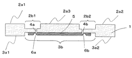
図1において、1は基板、2a(2a1,2a2,2a3)は基板1の一方の主面、2b(2b1,2b2)は基板1の一方の主面側に設けられた凹部(第1の凹部)、3a(3a1,3a2)は基板1の他方の主面、3bは他方の主面側に設けられた凹部(第2の凹部)、4(4a,4b)は光伝送孔、5は光導波路、および、6(6a,6b)は光路変換体を、それぞれ示す。
[Optical Transmission Board in First Aspect]
In FIG. 1, 1 is a substrate, 2a (2a1, 2a2, 2a3) is one main surface of the
ここで、上述した「基板1の一方の主面側」とは、一方の主面2aとともに、一方の主面2aに対して略同方向を向く面をいい、例えば、図1では、第1の凹部2bの底面を指す。
Here, the above-mentioned “one main surface side of the
基板1としては、例えば、一般的に使用されているエポキシ樹脂やセラミックなどからなるプリント配線基板が挙げられる。なかでも、機械的強度が大きく、熱による基板の反りに対して効果的な防止が可能となるため、両面に同じ厚さの樹脂絶縁層を形成した対称層構造を有するプリント配線基板が好ましく、両面の樹脂絶縁層の厚さが同じであることがより好ましい。基板の厚みとしては、0.5〜1.5mmとすることができる。
As the board |
また、基板1としては、具体的には多層基板が挙げられる。ここで、多層基板とは、電気配線層と絶縁層とが交互に複数積層されたものであればよく、例えば、コア基板と、配線基板表面側に形成されたビルドアップ層とからなる基板も含まれる。ここで、ビルドアップ層とは、電気配線層と絶縁層が交互に積層された多層基板であり、また、コア基板とは、ビルドアップ層が表面に設けられ、ビルドアップ層を支持する単層をいう。
Further, as the
図1に示すように、本発明の光伝送基板は、一方の主面2aと他方の主面3aとを有する基板1を本体とするものである。基板1には、第1の凹部2bと、第2の凹部3bと、第1の凹部2bから第2の凹部3bまでの間を貫通する光伝送孔4(4a,4b)と、が具えられる。
As shown in FIG. 1, the optical transmission board of the present invention has a main body of a
第1の凹部2bは、その内部に、発光素子または受光素子などの光半導体素子を設けることが可能な大きさを有するものである。具体的には、第1の凹部2bの深さは100〜500μmである。そして、光半導体素子を内部に設けることにより、基板1の一方の主面側から他方の主面側までの光の伝送距離を短縮できるとともに、一方の主面2a上に半導体集積回路素子を設けた場合、半導体集積回路素子の配置位置と光半導体素子の配置位置との間に段差を有することになるため、半導体集積回路素子による光半導体素子の温度変化を大きく抑えることができる。また、第1の凹部2bを設けることにより、基板の厚みが大きい場合には作製が困難であった小さい孔径を有する光伝送孔を容易に作製することができる。
The first recess 2b has such a size that an optical semiconductor element such as a light emitting element or a light receiving element can be provided therein. Specifically, the depth of the 1st recessed part 2b is 100-500 micrometers. By providing the optical semiconductor element inside, the light transmission distance from one main surface side of the
第1の凹部2bの内部には、光半導体素子とともに、VCSELドライバやTIA(トランスインピーダンスアンプ)などをともに設けることが可能な大きさであってもよい。 The first recess 2b may have a size capable of providing a VCSEL driver, a TIA (transimpedance amplifier), and the like together with the optical semiconductor element.
第1の凹部2bの作製方法としては、例えば基板1が多層基板である場合、多層基板を積層前に必要な層数に対して型抜きを行う方法や、多層基板を作製後に切削により削り取る方法などが挙げられる。とくに、広い面積にわたって凹部を形成する場合、製造コストおよびタクトタイムの観点から、型抜きによる方法が好ましい。また、多層基板がコア層とビルドアップ層とからなる多層基板である場合、第1の凹部2bは、ビルドアップ層をパターニングすることにより形成される。
For example, when the
また、図1に示すように、本発明の光伝送基板は、第1の凹部2bが設けられている一方の主面2aの反対側の他方の主面3aに第2の凹部3bが設けられていることが好ましく、第2の凹部3bの凹部内の底面に光伝送孔4が開口するとともに、この光伝送孔4と光学的に結合するように、光導波路5がさらに設けられていることが好ましい。そうすることによって、基板1の一方の主面側から他方の主面側までの光の伝送距離を短縮できる。また、本発明の光伝送基板に対してさらに光半導体素子を設け、光モジュールとした場合、光モジュールを多層配線基板(マザーボード)に実装する際に光導波路5を保護しながら他方の主面3aにて安定な実装が可能となる。
As shown in FIG. 1, the optical transmission board of the present invention is provided with the
第2の凹部3bの作製方法としては、上述した第1の凹部2bの作製方法と同様におこなうことができる。
The method for producing the
図1において光伝送孔4は、第1の凹部2bの底面から他方の主面側(この場合は、第2の凹部3bの底面)まで貫通し、光を伝送させるものである。ここで、「他方の主面側」とは、他方の主面3aとともに、他方の主面3aに対して略同方向を向く面をいい、例えば、図1では、第2の凹部3bの底面をいう。
In FIG. 1, the light transmission hole 4 penetrates from the bottom surface of the first recess 2b to the other main surface side (in this case, the bottom surface of the
光伝送孔4は第1の凹部2bの底面に開口しており、例えば、第1の凹部2b内に発光素子を設置した場合、発光素子から出射された光が開口部を通り光伝送孔に伝搬することによって、光伝送孔4に光が伝送される。光伝送孔4は、発光素子または受光素子が凹部内に設けられる場合、発光素子の発光部、または、受光素子の受光部に向かいあう位置に形成される。 The light transmission hole 4 is opened at the bottom surface of the first recess 2b. For example, when a light emitting element is installed in the first recess 2b, light emitted from the light emitting element passes through the opening and enters the light transmission hole. By propagating, light is transmitted to the light transmission hole 4. When the light emitting element or the light receiving element is provided in the recess, the light transmission hole 4 is formed at a position facing the light emitting part of the light emitting element or the light receiving part of the light receiving element.
また、第1の凹部2b内に、光半導体素子を設ける場合、光伝送孔4の孔径は、発光素子及び受光素子の各々の発光径または受光径と光路変換体の大きさにあわせ、光の広がりを考慮して決定される。受光部に対応する光伝送孔4の孔径は受光部よりも小さく、また、発光部に対応する光伝送孔4の孔径は発光部より大きく設定されることが最も好ましい。 Further, when the optical semiconductor element is provided in the first recess 2b, the hole diameter of the light transmission hole 4 is adjusted according to the light emission diameter or the light reception diameter of each of the light emitting element and the light receiving element and the size of the optical path changer. Determined by considering the spread. Most preferably, the hole diameter of the light transmission hole 4 corresponding to the light receiving part is smaller than that of the light receiving part, and the hole diameter of the light transmission hole 4 corresponding to the light emitting part is set larger than that of the light emitting part.
光伝送孔4の形成には、通常のプリント基板の穿孔工程に使用されるドリルやレーザーが好適に使用される。 For the formation of the light transmission hole 4, a drill or a laser used in a normal printed board drilling process is preferably used.
第1の凹部2bの底面内において開口している光伝送孔4の数は、光半導体素子の有するチャンネル数と同数であることが好ましい。例えば、4チャンネルアレイのVCSELを第1の凹部2bの内部に設けた場合、光伝送孔4の孔数は、VCSELのチャンネル数と同じ4個とすることが好ましい。このように、光伝送孔4の孔数を光半導体素子の有するチャンネル数と同じ数にすることにより、各チャンネルから出射または入射した光信号を正確に伝送することが可能となる。 The number of light transmission holes 4 opened in the bottom surface of the first recess 2b is preferably the same as the number of channels of the optical semiconductor element. For example, when a 4-channel array VCSEL is provided inside the first recess 2b, the number of light transmission holes 4 is preferably four, which is the same as the number of channels of the VCSEL. Thus, by setting the number of light transmission holes 4 to be the same as the number of channels of the optical semiconductor element, it is possible to accurately transmit an optical signal emitted or incident from each channel.
以上のように光伝送孔4の孔径および孔数を決定すると、例えば、発光部が直径15μmで250μmピッチの4チャンネルアレイのVCSELを使用する場合は、光伝送孔4も発光部に合わせて直径15μm以上およびピッチ250μmとして各々の発光部に対して同じ孔数である4個の光伝送孔を形成し、また、受光部が直径65μmで250μmピッチの4チャンネルアレイのPDを使用する場合は光伝送孔4を直径65μm以下およびピッチ250μmとして各々の受光部に対して同じ孔数である4個の光伝送孔を形成することが好ましい。 When the hole diameter and the number of holes of the light transmission hole 4 are determined as described above, for example, when a VCSEL having a diameter of 15 μm and a pitch of 250 μm is used, the light transmission hole 4 has a diameter corresponding to the light emitting part. Four light transmission holes having the same number of holes are formed for each light emitting part with a pitch of 15 μm or more and a pitch of 250 μm, and when a light receiving part uses a PD with a diameter of 65 μm and a pitch of 250 μm, a light beam It is preferable that the transmission holes 4 have a diameter of 65 μm or less and a pitch of 250 μm, and four light transmission holes having the same number of holes are formed for each light receiving portion.
光伝送孔4内には、光の伝送が可能な透明樹脂が設けられていることが好ましい。光伝送孔内の透明樹脂は一様な屈折率の単一樹脂であってもよい。とくに、透明樹脂としては、その屈折率の分布が径方向において中心部で高く、周辺部で低くなっている樹脂が最も好ましい。このような同心円状の屈折率の分布は、信号光を中心部に閉じ込める光閉じ込め作用を有している。透明樹脂としては、光伝送孔4の径方向において中心部から周辺部に向かって階段状に低くなるように形成された屈折率分布を具える透明樹脂(以下、透明樹脂A)、または、光伝送孔の径方向において中心部から周辺部に向かって同心円状に漸次低くなるように形成された屈折率分布を具える透明樹脂(以下、透明樹脂B)が好ましい。 It is preferable that a transparent resin capable of transmitting light is provided in the light transmission hole 4. The transparent resin in the light transmission hole may be a single resin having a uniform refractive index. In particular, the transparent resin is most preferably a resin whose refractive index distribution is high in the central portion and low in the peripheral portion in the radial direction. Such a concentric refractive index distribution has an optical confinement effect for confining signal light in the center. As the transparent resin, a transparent resin (hereinafter referred to as transparent resin A) having a refractive index distribution formed so as to decrease stepwise from the central portion toward the peripheral portion in the radial direction of the light transmission hole 4, or light A transparent resin (hereinafter referred to as transparent resin B) having a refractive index distribution formed so as to be gradually lowered concentrically from the central portion toward the peripheral portion in the radial direction of the transmission hole is preferable.
透明樹脂Aや透明樹脂Bの屈折率の分布は、光を照射すると屈折率が低下するフォトブリーチング現象を生じるポリシラン、あるいは光を照射した部分が現像により除去できる感光性のアクリル系樹脂やエポキシ樹脂等を用いて形成することができる。例えば、フォトブリーチング現象を利用する場合は、光伝送孔4にポリシランを充填し、加熱硬化させた後、フォトマスク(光伝送孔より小さい径の円形パターンの遮光部を具備する)を介して紫外光を照射して紫外光未照射部の屈折率を低下させ、最後にポストベークを行うことにより光伝送孔4内の透明樹脂に屈折率の分布を形成する。 The refractive index distribution of the transparent resin A and the transparent resin B is such that polysilane that causes a photo bleaching phenomenon in which the refractive index decreases when irradiated with light, or a photosensitive acrylic resin or epoxy that can be removed by developing the irradiated portion. It can be formed using a resin or the like. For example, when the photo bleaching phenomenon is used, the light transmission hole 4 is filled with polysilane, heated and cured, and then passed through a photomask (having a light shielding portion having a circular pattern with a diameter smaller than that of the light transmission hole). The refractive index distribution is formed in the transparent resin in the light transmission hole 4 by irradiating the ultraviolet light to lower the refractive index of the non-irradiated portion of the ultraviolet light and finally performing the post-baking.
また、紫外線硬化型のアクリル系樹脂やエポキシ系樹脂を用いる場合は、光伝送孔4にこれらの感光性ポリマー材料を充填し、加熱硬化させた後、フォトマスク(光伝送孔より小さい径の円形パターンの透光部を具備する)を介して紫外光を照射して現像を行うことにより紫外光照射部の樹脂を除去し、その後に光伝送孔4内の現像により除去された部分(光伝送孔中心部)に最初に充填した材料より屈折率の高い材料を充填し、フォトマスクを使用しないで紫外光を照射して硬化後、最後にポストベークを行うことにより、光伝送孔4内の透明樹脂に屈折率分布を形成する。 In the case of using an ultraviolet curable acrylic resin or epoxy resin, the light transmission hole 4 is filled with these photosensitive polymer materials and cured by heating, and then a photomask (a circular shape having a diameter smaller than that of the light transmission hole). The portion of the light transmission hole 4 that has been removed by the development (light transmission) is removed by performing development by irradiating ultraviolet light through the light transmitting portion of the pattern). In the center of the hole), a material having a higher refractive index than that of the first filling material is filled, cured by irradiating with ultraviolet light without using a photomask, and finally post-baking is performed. A refractive index distribution is formed in the transparent resin.
光導波路5は、基板1の他方の主面側の面に平行に設けられ、光を伝送する役割を果たすものである。光導波路5は、コア部と、これを取り囲み、コア部よりも屈折率の小さいクラッド部とから構成される。図1の場合、コア部は、光導波路5の中心軸側に位置する箇所であり、クラッド部は、コア部を包みこむように位置する箇所をいう。また、クラッド部において、基板1に近い側が下部クラッド部であり、基板1よりも遠い側が上部クラッド部とする。下部クラッド部および上部クラッド部を有する光導波路5は、コア部およびクラッド部のそれぞれの屈折率を調整することで良好な光伝搬が可能となる。光導波路のコア部およびクラッド部の形状や寸法は、例えば、マルチモードの光導波路の場合であれば、コア部の厚みを約50μmとすると、下部クラッド部および上部クラッド部の厚みを、それぞれコア部の半分の約25μmとして、約100μmの厚みの光導波路5とすることができる。
The
光導波路5は、第2の凹部3b内に設けられることが好ましい。そして、それにより、基板1の一方の主面側から他方の主面側までの光の伝送距離を短縮できる。また、本発明の光伝送基板に対してさらに光半導体素子を設け、光モジュールとした場合、光モジュールを多層配線基板(マザーボード)に実装する際に光導波路5を保護しながら他方の主面3aにて安定な実装が可能となる。
The
光導波路5は、第2の凹部3b内に作りこむ方法のほかに、光導波路5のみを別途作製して、基板1の第2の面の凹部3a上に貼りあわせる方法とすることもできる。光導波路5を基板1の第2の面の凹部に貼りあわせるには、マーカーを用意して光伝送孔4の位置と光導波路5のコア部の位置とを正確に位置合わせする。
In addition to the method of forming the
コア部を有する光導波路5の作製方法には、直接露光法、屈折率変化法(フォトブリーチング法)、反応性イオンエッチング法等がある。いずれの方法でも作製可能であるが、最も簡便で安定した作製方法としては、直接露光法があげられる。とくに、基板1上に直接作りこむ方法はフォトリソグラフィにより光伝送孔4の位置を確認しながらコア位置を決定でき、さらに、光伝送孔4と光導波路5のコア部との位置合わせが簡便となる。
Examples of a method for producing the
直接露光法で作製できる材料には、感光性を有するエポキシ樹脂、アクリル樹脂、ポリイミド樹脂などが上げられる。直接露光法では、コア部およびクラッド部に相当する材料を塗布・露光・現像することにより必要なパターンを得ることができる。例えば、ネガ型の感光性エポキシ樹脂を用いた場合、材料を塗布し、必要な箇所を露光する形のフォトマスクを用意して露光することにより、露光された部分の樹脂は硬化され、露光されていない部分の樹脂は現像により除去されることによって所望のパターンが得られる。この方法を下部クラッド部および上部クラッド部とコア部の両方に適用することにより、基板全体で必要な箇所にのみ光導波路5を形成することができる。
Examples of materials that can be manufactured by the direct exposure method include photosensitive epoxy resins, acrylic resins, and polyimide resins. In the direct exposure method, a necessary pattern can be obtained by applying, exposing, and developing materials corresponding to the core portion and the clad portion. For example, if a negative photosensitive epoxy resin is used, the exposed portion of the resin is cured and exposed by applying a material and preparing and exposing a photomask that exposes the necessary areas. By removing the unexposed resin by development, a desired pattern can be obtained. By applying this method to both the lower clad part and the upper clad part and the core part, the
前述のポリマー材料は、低温プロセスによる光導波路5の作製が可能で、大面積化への対応も容易であり、しかも低コストで作製することができるため、種々の基板1に形成できる点で好適である。特にエポキシ樹脂を用いた場合、基板として一般的に用いられるガラスエポキシ基板と同系列の材料であることから、密着性が良く、剥がれなどの不良が無く、信頼性が高いものとなる。感光性エポキシの他に、感光性ポリイミドもまた、耐久性に富み、従来、保護膜や封止樹脂として用いられていることから好適である。
The above-described polymer material is suitable in that it can be formed on
光路変換体6は、光伝送孔4と光導波路5の双方に対して光学的に結合したものであり、それにより、光伝送孔4と光導波路5との間で光の伝送方向を変換させるはたらきを有する。具体的には、光路変換体6が一定の傾斜角を有する光反射面であることにより、光の入射方向を反射方向へ変換させることができ、それにより、それぞれ光路方向の異なる光伝送孔4と光導波路5に対して光学的に結合させることを可能としたものである。
The optical path changer 6 is optically coupled to both the optical transmission hole 4 and the
図1において光路変換体6は、光導波路5の一部を斜めに切り取られることで得られた光反射面であるが、光導波路5とは別の部材からなるものでもよい。
In FIG. 1, the optical path changer 6 is a light reflecting surface obtained by obliquely cutting off a part of the
図1において、光路変換体6(6a,6b)は光導波路5を形成後、光伝送孔4の開口位置に対応した箇所に形成されたものである。光路変換体6の形成方法としては、一般的には先端が45度又は90度に加工されたダイヤモンドブレードを用いてダイシングソーで溝入れ加工することにより形成される。それ以外にも、光導波路5のパターニング時にグレイマスクや斜め露光等により斜面を形成する方法や、プリント基板切り分け時に使用するケガキ機などを用いる方法もあるが、安定性や加工精度、生産性を考慮した場合、ダイシングソーがもっとも好適である。
In FIG. 1, the optical path changer 6 (6 a, 6 b) is formed at a location corresponding to the opening position of the optical transmission hole 4 after the
光路変換体6は、光導波路5の中途の表面に形成された斜面の、または、金(Au),銀(Ag),白金(Pt),アルミニウム(Al),銅(Cu)等の様に光導波路5を導波する光に対して反射率の高い膜をその表面に形成したものとすることができる。
The optical path changer 6 has a slope formed on the intermediate surface of the
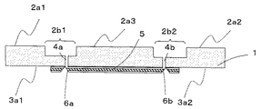
本発明の第一の態様における光伝送基板の別の例として、図2を示す。図2における光伝送基板は、図1とは異なり、光導波路を第2の凹部3b内ではなく他方の主面3a上に設けたものである。図2における光伝送基板についても、基板の主面間の光路長を短縮することができ、高い結合効率を得ることができる。
FIG. 2 shows another example of the optical transmission board according to the first aspect of the present invention. The optical transmission board in FIG. 2 differs from that in FIG. 1 in that an optical waveguide is provided not on the
〔本発明の光電子混載基板〕
本発明の光電子混載基板は、図3に示すように、本発明の図1の光伝送基板に対して、さらに電気配線層を具備させたものである。電気配線層の大半は、基板1中においてプリント配線基板中に形成されている(不図示)。
[Photoelectric mixed substrate of the present invention]
As shown in FIG. 3, the opto-electronic hybrid board of the present invention is obtained by further providing an electrical wiring layer with respect to the optical transmission board of FIG. 1 of the present invention. Most of the electric wiring layers are formed in the printed wiring board in the substrate 1 (not shown).
図3中において電気配線層の露出部7a(7a1,7a2)が一方の主面2a上に、また、露出部7b(7b1,7b2)が第1の凹部7の底面上に露出している。このように露出部7aおよび7bを有することにより、露出部7aには半導体集積回路素子を、また、露出部7bには光半導体素子を実装することが可能となる。
In FIG. 3, the exposed portion 7 a (7 a 1, 7 a 2) of the electric wiring layer is exposed on one main surface 2 a and the exposed portion 7 b (7
電気配線層は、一方の主面側の露出部7aおよび7bのほかに、他方の主面3a上にも電気配線層の露出部が形成されており(不図示)、この露出部は一方の主面側の露出部7aおよび7bと電気的に接続されている。このように他方の主面3a上にも電気配線層の露出部が形成されていることにより、基板1をドーターボードとして他のプリント基板(マザーボード)に実装する場合、第2の面3の電気配線5を使って電気的に接合できる。
In the electric wiring layer, in addition to the exposed portions 7a and 7b on one main surface side, an exposed portion of the electric wiring layer is also formed on the other main surface 3a (not shown). It is electrically connected to the exposed portions 7a and 7b on the main surface side. Since the exposed portion of the electric wiring layer is also formed on the other main surface 3a in this way, when the
基板1としてはプリント配線基板に限らず、基板内部の絶縁層にアルミナ等を用いたセラミック配線基板や、シリコンやガラス等に電気配線を形成した基板を用いてもよい。中でも、汎用性があり低コストに作製できるものとしては、ガラスエポキシ配線基板が好適である。
The
基板1における電気配線層の配線パターンは、通常のプリント基板製造工程中に、銅箔や銅箔付き樹脂のフォトリソグラフィ工程やエッチング工程により形成される。
The wiring pattern of the electric wiring layer in the
電気配線層5上には、電気配線層5との電気絶縁層と電気配線層5の保護を兼ねて、ソルダーレジスト層(不図示)が形成されてもよい。その場合、素子を実装するために最低限必要な箇所にはソルダーレジスト上に開口部を設け、開口部内の電気配線層5上に半田等を使って素子を実装する。基板1の第1の面の凹部2a内は特にソルダーレジストを必要とせず、電気配線層5が露出した形でもよい。
On the
[光モジュール]
本発明の光モジュールは、図4に示すように、本発明の図3の光電子混載基板に対して、さらに、発光素子8や受光素子9のような光半導体素子を具備させたものである。
[Optical module]
As shown in FIG. 4, the optical module of the present invention further comprises optical semiconductor elements such as a
図4に示す光モジュールは、発光素子8から受光素子9まで光を伝送させることができる光伝送経路を有する。発光素子8から発せられた光信号は、光伝送孔4aを介したのち光路変換体6aにて光の伝送方向が変換されて、光導波路5に伝送され、その後、光路変換体6bにて光の伝送方向が変換されたのち光伝送孔4bを介して受光素子9に入る。
The optical module shown in FIG. 4 has an optical transmission path through which light can be transmitted from the
上述のような光信号の伝送は、図4に示す光モジュールが二種類の光路変換体6aおよび6bを有するとともに、一方の光路変換体6aが、光導波路5の一端および発光素子8と光伝送孔4aを介して光学的に結合し、さらに、他方の光路変換体6bが、光導波路5の一端および受光素子9と光伝送孔4bを介して光学的に結合していることにより可能となる。
In the optical signal transmission as described above, the optical module shown in FIG. 4 has two types of
さらに、図4に示すように、発光素子8および受光素子9がそれぞれ、二組の凹部2b1および2b2に実装されていることにより、発光素子8から受光素子9までの光路長を短縮することができる。また、図4に示すように、二組の凹部2b1および2b2にはさらに、発光素子8とともにVCSELドライバ10を、また、受光素子9とともにTIA11を設けてもよい。
Furthermore, as shown in FIG. 4, the
以上のように本発明の光モジュールについて、図4として発光素子および受光素子が同一基板中にあるものを例にして説明したが、本発明の光モジュールは、発光素子および受光素子がそれぞれ同一基板中にないものも含まれる。また、図4として、発光素子が設けられた凹部と受光素子が設けられた凹部とが別のものを例にして説明したが、本発明の光モジュールは、発光素子および受光素子が同一の凹部に設けられたものも含まれる。 As described above, the optical module of the present invention has been described with reference to FIG. 4 in which the light emitting element and the light receiving element are on the same substrate. However, in the optical module of the present invention, the light emitting element and the light receiving element are respectively on the same substrate. Some are not inside. In FIG. 4, the concave portion provided with the light emitting element and the concave portion provided with the light receiving element are described as examples. However, in the optical module of the present invention, the concave portion in which the light emitting element and the light receiving element are the same. Also included in the above.
〔光電気回路システム〕
また、本発明の光電気回路システムは、図5に示すように、本発明の図4の光電子混載基板に対して、さらに、CPU12(セントラルプロセシングユニット)、GPU13(グラフィックスプロセッシングユニット)を具備させたものである。
[Optoelectric circuit system]
Further, as shown in FIG. 5, the opto-electric circuit system of the present invention further comprises a CPU 12 (central processing unit) and a GPU 13 (graphics processing unit) for the opto-electronic hybrid substrate of FIG. 4 of the present invention. It is a thing.
CPU12やGPU13のような半導体集積回路は、動作中に高温になり、多量の熱を放出し、とくに光半導体素子に温度変化を生じさせる傾向があるが、図5に示すように光半導体素子が第1の凹部2b中に実装されていることによって、段差により半導体集積回路からの熱が遮蔽され、光半導体素子の温度変化を防ぐことができるという効果が得られる。
A semiconductor integrated circuit such as the
なお、図5においては、〔光モジュール〕の説明において記載した発光素子8から受光素子9までの光伝送経路が、一組しか記載されていないが、本発明においては光伝送経路をさらにもう一組具えられていてもよい。そして、本発明の光電気回路システムが、CPUおよびGPUのように、二種類の半導体集積回路素子を有するとともに、それらが互いに異なる方向に光を転送するものである場合、双方向でデータ転送をおこなうことができる。
In FIG. 5, only one set of optical transmission paths from the
また、上述したように、半導体集積回路は多量の熱を放出する傾向があるため、一般的に半導体集積回路上には、ヒートシンクのような巨大な冷却装置が設けられる。そして、冷却装置を光モジュールに実装する場合に、冷却装置によって光半導体素子が損傷しやすい傾向があった。それに対して図6に記載したように、本発明の光モジュールでは、光半導体素子が第1の凹部2a内に設けられているため、ヒートシンク14による損傷の可能性も少なくなるとともに、ヒートシンク14により光半導体素子が覆われているため、外部からのノイズとなる光信号の入射を防ぐことができる。
Further, as described above, since a semiconductor integrated circuit tends to release a large amount of heat, a huge cooling device such as a heat sink is generally provided on the semiconductor integrated circuit. When the cooling device is mounted on the optical module, the optical semiconductor element tends to be easily damaged by the cooling device. In contrast, as shown in FIG. 6, in the optical module of the present invention, since the optical semiconductor element is provided in the first recess 2a, the possibility of damage by the
光半導体素子は、第1の面の凹部2aを利用して、アンダーフィルで固定後、樹脂でモールドすることにより、温度変化や振動などの外的変動要因から素子を保護することができる。ここで、アンダーフィルとしては、透明な絶縁性を有する樹脂が用いられ、具体的には、エポキシ樹脂などが挙げられる。 The optical semiconductor element can protect the element from external variation factors such as temperature change and vibration by fixing with underfill using the concave portion 2a on the first surface and then molding with resin. Here, as the underfill, a resin having a transparent insulating property is used, and specific examples include an epoxy resin.
[第二の態様における光伝送基板]
第二の態様における光伝送基板の具体例として図7を示す。15は実装手段であるはんだ、16はアンダーフィル、17は第2光伝送基板、18は第2光伝送基板17に設けられた光導波路、および、19は光導波路18に設けられた光路変換体を示す。
[Optical Transmission Board in Second Aspect]
FIG. 7 shows a specific example of the optical transmission board in the second mode. 15 is a solder as mounting means, 16 is an underfill, 17 is a second optical transmission board, 18 is an optical waveguide provided on the second
第二の態様における光伝送基板は、別の基板(以下、第2光伝送基板17)に実装され、用いられるものである。なお、第二の態様における基板が具える凹部および光伝送孔は、上述した第一の態様における光伝送基板における基板のものと同様であるため、説明を省略する。 The optical transmission board in the second mode is mounted and used on another board (hereinafter, second optical transmission board 17). In addition, since the recessed part and optical transmission hole which the board | substrate in a 2nd aspect provides are the same as that of the board | substrate in the optical transmission board | substrate in a 1st aspect mentioned above, description is abbreviate | omitted.
図7において、第2光伝送基板17は、光の入出力可能箇所として、光路変換体19を有する。ここで、光の入出力可能箇所とは、光伝送孔4に光を入力または出力することができればよく、光路変換体19の他に、例えば、光半導体素子であってもよい。また、光路変換体19は、光導波路18の一部を斜めに切り取ることで得られた光反射面でも、光導波路18とは別の部材からなるものでもよい。
In FIG. 7, the second
第二の態様における光伝送基板の実装手段は、光路変換体19と光伝送孔24とが光学的に結合するように光伝送基板を第2光伝送基板17に実装させるものであり、さらに、光伝送基板を、第2光伝送基板は17と電気的に接続させるものである。
The means for mounting the optical transmission board in the second aspect is to mount the optical transmission board on the second
具体的な実装手段としては、例えば、BGA(Ball Grid Array),PGA(Pin Grid Array),LGA(Land Grid Array)等が挙げられ、図7の場合は、はんだボール15を使用したBGAを実装手段として開示している。なお、図7に示すように、実装手段として用いたはんだボール15の厚みが光導波路18の厚みよりも大きい場合に生じた空隙部には、アンダーフィルなどにより充填される。
Specific mounting means include, for example, BGA (Ball Grid Array), PGA (Pin Grid Array), LGA (Land Grid Array), etc. In the case of FIG. 7, BGA using
参考例の第二の態様における光電子混載基板は、本発明の第一の態様における光電子混載基板と同様に、さらに電気配線層を具備させたものである。そして、電気配線層の大半は、基板1中においてプリント配線基板中に形成されている(不図示)。電気配線層の露出部は、その他方の主面上に形成されており、はんだなどの実装手段と接続する。そして、それにより、光電気混載基板と第2光伝送基板とを電気的に接続させることができる。 The opto-electronic hybrid substrate in the second embodiment of the reference example is provided with an electric wiring layer, similarly to the opto-electronic hybrid substrate in the first embodiment of the present invention. And most of the electrical wiring layers are formed in the printed wiring board in the substrate 1 (not shown). The exposed portion of the electric wiring layer is formed on the other main surface and is connected to mounting means such as solder. Thereby, the opto-electric hybrid board and the second optical transmission board can be electrically connected.
参考例の第二の態様における光モジュールは、本発明の第一の態様における光モジュールと同様に、光電子混載基板に対して、さらに、発光素子や受光素子のような光半導体素子を具備させたものである。第一の態様における光伝送経路では、光導波路および光路変換体は発光素子および受光素子と同一の基板に実装されたものであったが、本発明の第二の態様においての光伝送経路および光路変換体はそれに限られず、光伝送経路および光路変換体は、第2光伝送基板に設けられていてもよい。 The optical module according to the second aspect of the reference example is further provided with an optical semiconductor element such as a light emitting element or a light receiving element with respect to the opto-electronic hybrid substrate, similarly to the optical module according to the first aspect of the present invention. Is. In the optical transmission path in the first aspect, the optical waveguide and the optical path changer were mounted on the same substrate as the light emitting element and the light receiving element, but the optical transmission path and optical path in the second aspect of the present invention The converter is not limited thereto, and the optical transmission path and the optical path converter may be provided on the second optical transmission board.
その他の記載に関しては、本発明の第一の態様における光モジュールと同様である。 Other descriptions are the same as those of the optical module according to the first aspect of the present invention.
参考例の第二の態様における光電気回路システムは、本発明の第一の態様における光電気回路システムと同様に、光モジュールに一方の主面上において、電気配線層の露出部に実装された半導体集積回路素子とを具備させたものである。本発明の第一の態様における光電気回路システムと同様に、光伝送経路が二組の互いに異なる方向に光を転送するものであってもよく、また、半導体集積回路素子によって生じた熱を放散させる冷却装置をさらに具備するものでもよい。 The photoelectric circuit system according to the second aspect of the reference example was mounted on the exposed portion of the electrical wiring layer on one main surface of the optical module, similarly to the photoelectric circuit system according to the first aspect of the present invention. And a semiconductor integrated circuit element. Similar to the optoelectric circuit system according to the first aspect of the present invention, the optical transmission path may transfer two sets of light in different directions, and dissipates heat generated by the semiconductor integrated circuit element. It may further comprise a cooling device.
[第三の態様における光伝送基板]
本発明の第三の態様における光伝送基板、光電子混載基板、および光モジュールは、他方の主面側に凹部が形成され、さらに、該凹部内に光導波路5が形成されている点が必須である点以外は、本発明の第一の態様における光伝送基板、光電子混載基板、および光モジュールと同様である(図8参照)。そして、得られる効果についても、主面間の光伝送方向を短縮することであり、本発明の第一の態様の光伝送基板、光電子混載基板、および光モジュールと同様であるため、説明を省略する。
[Optical Transmission Board in Third Aspect]
The optical transmission board, the opto-electronic hybrid board, and the optical module according to the third aspect of the present invention are indispensable in that a concave portion is formed on the other main surface side, and an
以下、実施例にもとづいて、図4の光モジュールの具体的な作製工程を詳細に説明するが、本発明はこの実施例に限定されるものではなく、本発明の要旨を逸脱しない範囲内で種々の変更を施すことができる。 Hereinafter, the specific manufacturing process of the optical module of FIG. 4 will be described in detail based on the examples. However, the present invention is not limited to these examples, and the scope of the present invention is not deviated. Various changes can be made.
<第1の凹部2bおよび第2の凹部3bを有する基板1の作製工程>
まず、厚み0.7mmの多層配線基板を作製する。この多層配線基板は、厚さが0.1mmの基板を7個積層させたものである。なお、上述した厚さが0.1mmの基板は、電気配線層と絶縁層(エポキシ樹脂)とを重ね合わせて加熱押圧することにより作製した。
<The manufacturing process of the board |
First, a multilayer wiring board having a thickness of 0.7 mm is manufactured. This multilayer wiring board is obtained by laminating seven substrates having a thickness of 0.1 mm. In addition, the board | substrate with a thickness of 0.1 mm mentioned above was produced by overlapping and heating-pressing an electric wiring layer and an insulating layer (epoxy resin).
上述した厚さが0.1mmの基板のうち、型抜きが必要なものについては、それらを積層する前に、必要な箇所について型抜きをおこなった。ここで、型抜きが必要な箇所とは、積層後に第1の凹部2b1および2b2、ならびに第2の凹部3bとなる箇所をいう。第1の凹部2b1および2b2については3層分(0.3mm)の型抜きをおこない、第2の凹部3bについては2層分(0.2mm)の型抜きをおこなった。
Of the above-described substrates having a thickness of 0.1 mm, those requiring die cutting were die-cut at necessary locations before they were laminated. Here, the location that needs to be punched refers to a location that becomes the first recesses 2b1 and 2b2 and the
型抜きをおこなったのち、上述した厚さが0.1mmの基板を7層積層し、さらに、従来のプリント配線板の作製工程(穿孔工程、鍍金工程など)と同様の工程をおこなうことにより、第1の凹部2b1および2b2と第2の凹部3bとを有する基板1を作製した。なお、基板1は、一方の主面2a1上において電気配線層の露出部7a1が、一方の主面2a2上において電気配線層の露出部7a2がそれぞれ露出している。また、第1の凹部2b1の底面上において電気配線層の露出部7b1が、第1の凹部2b2の底面上において電気配線層の露出部7b2がそれぞれ露出している。そして、露出部7a1が露出部7b1と電気的に接合され、また、露出部7a2が露出部7b2と電気的に接合されている。なお、他方の主面3a1上および他方の主面3a2上においても電気配線層が露出している(不図示)。また、最表面にソルダーレジスト層が形成されている。
After performing die cutting, seven layers of the above-mentioned substrate having a thickness of 0.1 mm are laminated, and further, by performing the same process as the conventional printed wiring board production process (for example, perforation process, plating process), The
以上の工程により、2箇所の第1の凹部2bおよび1箇所の第2の凹部3bを有する基板1を作製した。なお、基板1において、第1の凹部2bと第2の凹部3bとの間に挟まれた基板1の箇所の厚さは0.2mmとなっている。
The
<光伝送孔4a,4bの作製工程>
ドリルを用いて、第1の凹部2b1の底面から第2の凹部3bの底面まで、および、第1の凹部2b2の底面から第2の凹部3bの底面まで、それぞれ直径が90μmの光伝送孔4aを4個、250μmピッチで作製した。なお、光伝送孔4aの個数と直径とピッチの長さは、後述する工程において第1の凹部2b1の凹部内に搭載されるVCSEL(発光径が15μmであり、発光部の間隔が250μmピッチである4チャンネルアレイ)および第2の凹部3bの凹部内に設けられるPD(受光径が65μmであり、発光部の間隔が250μmピッチである4チャンネルアレイ)に合わせたものである。
<Process for producing
Using a drill, an
<光伝送孔4aおよび4bへの透明樹脂の充填工程>
絶縁層と同様にエポキシ樹脂を、光伝送孔4aおよび光伝送孔4bの内部に充填し、紫外線照射およびベークをおこなってエポキシ樹脂を硬化させることによって透明樹脂14aおよび14bを充填した。
<Filling process of transparent resin into
In the same manner as the insulating layer, epoxy resin was filled in the
<光導波路5の作製工程>
(下部クラッド部)
第2の凹部3bの底面全体に対して、エポキシ樹脂をスピンコートにより塗布し、プリベークをおこなった。次に、第2の凹部3b内に、下部クラッド部のパターンに合わせてCr膜がエッチングされているフォトマスクを用い、残すべき箇所に露光をおこなった。その際、フォトマスクと基板との位置合わせは、位置合わせマーカーを用いて行った。位置合わせマーカーは基板形成時にソルダーレジストパターン、メタルパターン、光伝送孔などにより用意することができる。
<Process for producing
(Lower cladding)
An epoxy resin was applied to the entire bottom surface of the
そして、未露光部を現像により除去したのち、ポストベークを行うことで下部クラッド部6bを形成した。なお、下部クラッド部の厚さは25μmであった。
And after removing the unexposed part by development, the lower
(コア部)
下部クラッド部に対する比屈折率差Δn=1.4%の材料を、スピンコートにより下部クラッド部に塗布し、プリベークをおこなった。下部クラッド部のパターンに合わせてCr膜がエッチングされているフォトマスクを用い、残すべき箇所に露光をおこなった。なお、フォトマスクと基板との位置合わせは、フォトマスク上で透明になっているコアパターンから、下部クラッド部を通して光伝送孔4を確認しながらマスク合わせを行うことで正確な位置あわせを行なった。
(Core part)
A material having a relative refractive index difference Δn = 1.4% with respect to the lower clad portion was applied to the lower clad portion by spin coating and prebaked. Using a photomask in which the Cr film was etched in accordance with the pattern of the lower clad portion, exposure was performed on the portion to be left. The alignment between the photomask and the substrate was performed accurately from the core pattern that is transparent on the photomask by performing mask alignment while confirming the light transmission hole 4 through the lower clad portion. .
そして、未露光部を現像により除去したのち、ポストベークを行うことでコア部を形成した。なお、コア部の厚さは50μmであった。 And after removing the unexposed part by development, the core part was formed by performing post-baking. The core portion had a thickness of 50 μm.
(上部クラッド部)
下部クラッド部の作製工程と同様にして、コア部の上に上部クラッド部を作製した。なお、厚さも下部クラッド部と同様に25μmであった。
(Upper clad part)
The upper clad part was produced on the core part similarly to the production process of the lower clad part. The thickness was 25 μm as in the lower clad portion.
以上の工程をおこなうことにより、光導波路5を作製した。
The
<光路変換体の形成工程>
光導波路5のうち、中途の光伝送孔4aおよび4bの開口位置に対応する光導波路5の表面に対しダイシングソーにより、断面がV字型となるように加工を行なって、光路変換体61および62を作製した。断面の深さは、光導波路5の表面から約80μm、下部クラッド部まで達するものとした。なお、ダイシングソーとしては、ブレードとして先端が90度に加工され、さらに厚さが200μmのものを使用した。
<Formation process of optical path changer>
The surface of the
以上の工程によって光電子混載基板を作製した。 The opto-electronic hybrid substrate was fabricated through the above steps.
<発光素子および受光素子の搭載>
光電子混載基板に対して、発光部が光伝送孔4の開口部と向かい合うように、発光素子8を第1の凹部2bの光伝送孔4上に実装した。同様に、受光部が光伝送孔4の開口部と向かい合うように、受光素子8を第1の凹部2bの光伝送孔4上に実装した。更に、受光素子9を第1の凹部2bの光伝送孔4上に、受光部と開口部とが向かい合った形となるように実装した。
<Installation of light emitting element and light receiving element>
The
以上の工程をおこなうことにより、図4の光モジュールを容易に作製することができた。 By performing the above steps, the optical module of FIG. 4 could be easily manufactured.
1、21、31 基板
2a、22a、32a 一方の主面
2b、22b、32b 一方の主面側に設けられた凹部(第1の凹部)
3a、23a、33a 他方の主面
3b、23b、33b 他方の主面側に設けられた凹部(第2の凹部)
4、24、34 光伝送孔
5、18、35 光導波路
6、19、36 光路変換体
7 電気配線層の露出部
8 発光素子
9 受光素子
10 VCSELドライバ
11 TIA
12 CPU
13 GPU
14 ヒートシンク
15 はんだボール
16 アンダーフィル
17 第2光伝送基板
1, 21, 31
3a, 23a, 33a The other
4, 24, 34 Optical transmission holes 5, 18, 35 Optical waveguide 6, 19, 36
12 CPU
13 GPU
14
Claims (9)
前記第2の凹部内に全体が収容され、且つ前記第2の凹部の深さよりも厚みが薄い光導波路と、
前記光伝送孔と前記光導波路との間で光伝送方向を変換させるべく、前記光伝送孔および前記光導波路の双方に対して光学的に結合した光路変換体と、
を具備する光伝送基板。 A concave portion provided on one main surface side for housing and providing an optical semiconductor element, a second concave portion provided on the other main surface side, and from a bottom surface of the concave portion to a bottom surface of the second concave portion A light transmission hole that opens between the bottom surface of the recess and the bottom surface of the second recess,
An optical waveguide that is entirely accommodated in the second recess, and that is thinner than the depth of the second recess ;
An optical path changer optically coupled to both the optical transmission hole and the optical waveguide to change the optical transmission direction between the optical transmission hole and the optical waveguide;
An optical transmission board comprising:
前記凹部の底面および前記一方の主面上に少なくとも一部が露出した露出部を具える電気配線層と、
を具備する光電子混載基板。 The optical transmission board according to claim 1 or 2 ,
An electrical wiring layer comprising an exposed portion at least partially exposed on the bottom surface of the recess and the one main surface;
An opto-electronic hybrid board comprising:
前記凹部内において、前記電気配線層の露出部に実装され、前記光伝送孔と光学的に結合した光半導体素子と、
を具備する光モジュール。 The optoelectronic hybrid substrate according to claim 3 or 4 ,
In the recess, an optical semiconductor element mounted on the exposed portion of the electrical wiring layer and optically coupled to the light transmission hole;
An optical module comprising:
前記光半導体素子は、発光素子および受光素子の二種類であって、前記二組の凹部内のそれぞれに実装され、
前記光路変換体は二組であって、一方が前記光導波路の一端と前記発光素子とを、他方が前記光導波路の他端と前記受光素子とを、それぞれ前記二組の光伝送孔を介して光学的に結合している光伝送経路を有する請求項5に記載の光モジュール。 The substrate has two sets of the recess and the light transmission hole,
The optical semiconductor element is a light emitting element and a light receiving element, and is mounted in each of the two sets of recesses,
There are two sets of optical path changers, one through one end of the optical waveguide and the light emitting element, and the other through the two sets of optical transmission holes, the other end of the optical waveguide and the light receiving element, respectively. the optical module according to 請 Motomeko 5 that have a light transmission path are optically coupled Te.
前記一方の主面上において、前記電気配線層の露出部に実装された半導体集積回路素子と、
を具備する光電気回路システム。 The optical module according to claim 5 or 6 ,
A semiconductor integrated circuit element mounted on an exposed portion of the electrical wiring layer on the one main surface;
A photoelectric circuit system comprising:
前記基板には、前記光伝送経路がさらにもう一組具えられ、これら二組の光伝送経路が互いに異なる方向に光を転送することによって前記データ転送を行なう、請求項6に係る請求項7に記載の光電気回路システム。 The semiconductor integrated circuit element is of two types, and is configured to transfer data between the two.
The substrate, the optical transmission path is further comprising another set, perform the data transfer by the two sets of the optical transmission path to transfer different directions of light from each other, in claim 7 according to claim 6 The optoelectric circuit system described.
Priority Applications (1)
| Application Number | Priority Date | Filing Date | Title |
|---|---|---|---|
| JP2006292997A JP5328095B2 (en) | 2006-10-27 | 2006-10-27 | Optical transmission board, opto-electronic hybrid board, optical module, and optoelectric circuit system |
Applications Claiming Priority (1)
| Application Number | Priority Date | Filing Date | Title |
|---|---|---|---|
| JP2006292997A JP5328095B2 (en) | 2006-10-27 | 2006-10-27 | Optical transmission board, opto-electronic hybrid board, optical module, and optoelectric circuit system |
Publications (2)
| Publication Number | Publication Date |
|---|---|
| JP2008111862A JP2008111862A (en) | 2008-05-15 |
| JP5328095B2 true JP5328095B2 (en) | 2013-10-30 |
Family
ID=39444420
Family Applications (1)
| Application Number | Title | Priority Date | Filing Date |
|---|---|---|---|
| JP2006292997A Expired - Fee Related JP5328095B2 (en) | 2006-10-27 | 2006-10-27 | Optical transmission board, opto-electronic hybrid board, optical module, and optoelectric circuit system |
Country Status (1)
| Country | Link |
|---|---|
| JP (1) | JP5328095B2 (en) |
Cited By (1)
| Publication number | Priority date | Publication date | Assignee | Title |
|---|---|---|---|---|
| CN103760635A (en) * | 2014-01-28 | 2014-04-30 | 华进半导体封装先导技术研发中心有限公司 | Glass base three-dimension photoelectricity simultaneous transmitting device and manufacturing method thereof |
Families Citing this family (5)
| Publication number | Priority date | Publication date | Assignee | Title |
|---|---|---|---|---|
| JP5071247B2 (en) * | 2008-05-30 | 2012-11-14 | 凸版印刷株式会社 | Photoelectric substrate manufacturing method |
| JP5094636B2 (en) * | 2008-08-25 | 2012-12-12 | 新光電気工業株式会社 | Package for optoelectric wiring |
| JP5614018B2 (en) * | 2009-09-17 | 2014-10-29 | 日立化成株式会社 | Optical waveguide and optoelectric composite substrate manufacturing method, and optical waveguide and optoelectric composite substrate obtained thereby |
| JP2014044409A (en) * | 2012-07-30 | 2014-03-13 | Kyocera Corp | Optical device component, optical device, and optical module |
| JP2015121592A (en) * | 2013-12-20 | 2015-07-02 | 京セラ株式会社 | Substrate for optical device, optical device, and optical module |
Family Cites Families (9)
| Publication number | Priority date | Publication date | Assignee | Title |
|---|---|---|---|---|
| US4897711A (en) * | 1988-03-03 | 1990-01-30 | American Telephone And Telegraph Company | Subassembly for optoelectronic devices |
| KR940005309B1 (en) * | 1991-10-02 | 1994-06-16 | 재단법인 한국기계연구소 | Automatic parts apply device for machine tool |
| JP2000081524A (en) * | 1998-09-07 | 2000-03-21 | Sony Corp | Light transmitter-receiver system |
| TW451084B (en) * | 1999-06-25 | 2001-08-21 | Toppan Printing Co Ltd | Optical-electro wiring board, mounted board, and manufacturing method of optical-electro wiring board |
| JP2003222746A (en) * | 2002-01-29 | 2003-08-08 | Mitsubishi Electric Corp | Photoelectric coupling device |
| US6965714B2 (en) * | 2002-06-13 | 2005-11-15 | Northrop Grumman Corporation | Integrated aspheric optical coupler for RF planarized automatic photonics packaging |
| JP2004294857A (en) * | 2003-03-27 | 2004-10-21 | Fujitsu Ltd | Optical coupler and optical element built-in substrate |
| JP2004327516A (en) * | 2003-04-22 | 2004-11-18 | Toppan Printing Co Ltd | Multilayered substrate effective for optical and electrical utility and its manufacturing method |
| JP2005201937A (en) * | 2004-01-13 | 2005-07-28 | Sony Corp | Optical waveguide array and manufacturing method thereof |
-
2006
- 2006-10-27 JP JP2006292997A patent/JP5328095B2/en not_active Expired - Fee Related
Cited By (1)
| Publication number | Priority date | Publication date | Assignee | Title |
|---|---|---|---|---|
| CN103760635A (en) * | 2014-01-28 | 2014-04-30 | 华进半导体封装先导技术研发中心有限公司 | Glass base three-dimension photoelectricity simultaneous transmitting device and manufacturing method thereof |
Also Published As
| Publication number | Publication date |
|---|---|
| JP2008111862A (en) | 2008-05-15 |
Similar Documents
| Publication | Publication Date | Title |
|---|---|---|
| JP4260650B2 (en) | Photoelectric composite substrate and manufacturing method thereof | |
| JP4690870B2 (en) | Opto-electric integrated wiring board and opto-electric integrated wiring system | |
| KR100460703B1 (en) | Electro-optical circuit board having unified optical transmission/receiving module and optical waveguide | |
| JP5014855B2 (en) | Opto-electric integrated wiring board, manufacturing method thereof, and opto-electric integrated wiring system | |
| JP5670169B2 (en) | Manufacturing method of optical waveguide | |
| JP2007004043A (en) | Wiring board, module using wiring board, and module assembly | |
| JP5328095B2 (en) | Optical transmission board, opto-electronic hybrid board, optical module, and optoelectric circuit system | |
| JP2006351718A (en) | Optical element and optical module using it | |
| WO2010113968A1 (en) | Optical and electrical circuit board and optical module | |
| JP2013257381A (en) | Optical module and method for manufacturing optical module | |
| JP2006258835A (en) | Optical waveguide module, photoelectric converter and optical waveguide member | |
| JP2011237503A (en) | Photoelectric composite substrate and method of manufacturing the same | |
| JP4321267B2 (en) | Photoelectric composite device, optical waveguide used in the device, and mounting structure of photoelectric composite device | |
| JP2008158388A (en) | Opto-electrical circuit board, optical module, and opto-electrical circuit system | |
| JP4164757B2 (en) | Photoelectric composite device, socket used in this device, and mounting structure of photoelectric composite device | |
| JP5349192B2 (en) | Optical wiring structure and optical module having the same | |
| JP2004198579A (en) | Optical waveguide array and optical element surface mounted device | |
| JP2004302188A (en) | Electric wiring substrate with optical waveguide | |
| JP2007086367A (en) | Optical pin, optical pin connector and optical path conversion module | |
| JP2008134492A (en) | Optical transmission system and optical module equipped with same | |
| JP5253083B2 (en) | OPTICAL TRANSMISSION BOARD, OPTICAL MODULE, AND OPTICAL TRANSMISSION BOARD MANUFACTURING METHOD | |
| JP5976769B2 (en) | Optical waveguide and optical waveguide device | |
| JP2005115190A (en) | Opto-electric composite wiring board and laminated optical waveguide structure | |
| JP5136142B2 (en) | Optical substrate manufacturing method | |
| JP2006310417A (en) | Photoelectric converter, its manufacturing method and optical information processor |
Legal Events
| Date | Code | Title | Description |
|---|---|---|---|
| A621 | Written request for application examination |
Free format text: JAPANESE INTERMEDIATE CODE: A621 Effective date: 20090318 |
|
| A977 | Report on retrieval |
Free format text: JAPANESE INTERMEDIATE CODE: A971007 Effective date: 20101115 |
|
| A131 | Notification of reasons for refusal |
Free format text: JAPANESE INTERMEDIATE CODE: A131 Effective date: 20120110 |
|
| A521 | Written amendment |
Free format text: JAPANESE INTERMEDIATE CODE: A523 Effective date: 20120229 |
|
| A131 | Notification of reasons for refusal |
Free format text: JAPANESE INTERMEDIATE CODE: A131 Effective date: 20130402 |
|
| A521 | Written amendment |
Free format text: JAPANESE INTERMEDIATE CODE: A523 Effective date: 20130603 |
|
| TRDD | Decision of grant or rejection written | ||
| A01 | Written decision to grant a patent or to grant a registration (utility model) |
Free format text: JAPANESE INTERMEDIATE CODE: A01 Effective date: 20130625 |
|
| A61 | First payment of annual fees (during grant procedure) |
Free format text: JAPANESE INTERMEDIATE CODE: A61 Effective date: 20130723 |
|
| R150 | Certificate of patent or registration of utility model |
Ref document number: 5328095 Country of ref document: JP Free format text: JAPANESE INTERMEDIATE CODE: R150 Free format text: JAPANESE INTERMEDIATE CODE: R150 |
|
| LAPS | Cancellation because of no payment of annual fees |