JP5328074B2 - Improved electrophysiology catheter - Google Patents
Improved electrophysiology catheter Download PDFInfo
- Publication number
- JP5328074B2 JP5328074B2 JP2004548623A JP2004548623A JP5328074B2 JP 5328074 B2 JP5328074 B2 JP 5328074B2 JP 2004548623 A JP2004548623 A JP 2004548623A JP 2004548623 A JP2004548623 A JP 2004548623A JP 5328074 B2 JP5328074 B2 JP 5328074B2
- Authority
- JP
- Japan
- Prior art keywords
- distal end
- tip assembly
- catheter
- shaft
- assembly
- Prior art date
- Legal status (The legal status is an assumption and is not a legal conclusion. Google has not performed a legal analysis and makes no representation as to the accuracy of the status listed.)
- Expired - Fee Related
Links
Images


Classifications
-
- A—HUMAN NECESSITIES
- A61—MEDICAL OR VETERINARY SCIENCE; HYGIENE
- A61B—DIAGNOSIS; SURGERY; IDENTIFICATION
- A61B18/00—Surgical instruments, devices or methods for transferring non-mechanical forms of energy to or from the body
- A61B18/04—Surgical instruments, devices or methods for transferring non-mechanical forms of energy to or from the body by heating
- A61B18/12—Surgical instruments, devices or methods for transferring non-mechanical forms of energy to or from the body by heating by passing a current through the tissue to be heated, e.g. high-frequency current
- A61B18/14—Probes or electrodes therefor
- A61B18/1492—Probes or electrodes therefor having a flexible, catheter-like structure, e.g. for heart ablation
-
- A—HUMAN NECESSITIES
- A61—MEDICAL OR VETERINARY SCIENCE; HYGIENE
- A61B—DIAGNOSIS; SURGERY; IDENTIFICATION
- A61B5/00—Measuring for diagnostic purposes; Identification of persons
- A61B5/24—Detecting, measuring or recording bioelectric or biomagnetic signals of the body or parts thereof
- A61B5/25—Bioelectric electrodes therefor
- A61B5/279—Bioelectric electrodes therefor specially adapted for particular uses
- A61B5/28—Bioelectric electrodes therefor specially adapted for particular uses for electrocardiography [ECG]
- A61B5/283—Invasive
- A61B5/287—Holders for multiple electrodes, e.g. electrode catheters for electrophysiological study [EPS]
-
- A—HUMAN NECESSITIES
- A61—MEDICAL OR VETERINARY SCIENCE; HYGIENE
- A61B—DIAGNOSIS; SURGERY; IDENTIFICATION
- A61B5/00—Measuring for diagnostic purposes; Identification of persons
- A61B5/68—Arrangements of detecting, measuring or recording means, e.g. sensors, in relation to patient
- A61B5/6846—Arrangements of detecting, measuring or recording means, e.g. sensors, in relation to patient specially adapted to be brought in contact with an internal body part, i.e. invasive
- A61B5/6847—Arrangements of detecting, measuring or recording means, e.g. sensors, in relation to patient specially adapted to be brought in contact with an internal body part, i.e. invasive mounted on an invasive device
- A61B5/6852—Catheters
- A61B5/6856—Catheters with a distal loop
-
- A—HUMAN NECESSITIES
- A61—MEDICAL OR VETERINARY SCIENCE; HYGIENE
- A61B—DIAGNOSIS; SURGERY; IDENTIFICATION
- A61B18/00—Surgical instruments, devices or methods for transferring non-mechanical forms of energy to or from the body
- A61B18/18—Surgical instruments, devices or methods for transferring non-mechanical forms of energy to or from the body by applying electromagnetic radiation, e.g. microwaves
- A61B18/1815—Surgical instruments, devices or methods for transferring non-mechanical forms of energy to or from the body by applying electromagnetic radiation, e.g. microwaves using microwaves
-
- A—HUMAN NECESSITIES
- A61—MEDICAL OR VETERINARY SCIENCE; HYGIENE
- A61B—DIAGNOSIS; SURGERY; IDENTIFICATION
- A61B18/00—Surgical instruments, devices or methods for transferring non-mechanical forms of energy to or from the body
- A61B2018/00053—Mechanical features of the instrument of device
- A61B2018/00273—Anchoring means for temporary attachment of a device to tissue
-
- A—HUMAN NECESSITIES
- A61—MEDICAL OR VETERINARY SCIENCE; HYGIENE
- A61B—DIAGNOSIS; SURGERY; IDENTIFICATION
- A61B18/00—Surgical instruments, devices or methods for transferring non-mechanical forms of energy to or from the body
- A61B2018/00315—Surgical instruments, devices or methods for transferring non-mechanical forms of energy to or from the body for treatment of particular body parts
- A61B2018/00345—Vascular system
- A61B2018/00351—Heart
- A61B2018/00375—Ostium, e.g. ostium of pulmonary vein or artery
-
- A—HUMAN NECESSITIES
- A61—MEDICAL OR VETERINARY SCIENCE; HYGIENE
- A61B—DIAGNOSIS; SURGERY; IDENTIFICATION
- A61B18/00—Surgical instruments, devices or methods for transferring non-mechanical forms of energy to or from the body
- A61B2018/00636—Sensing and controlling the application of energy
- A61B2018/00773—Sensed parameters
- A61B2018/00791—Temperature
-
- A—HUMAN NECESSITIES
- A61—MEDICAL OR VETERINARY SCIENCE; HYGIENE
- A61B—DIAGNOSIS; SURGERY; IDENTIFICATION
- A61B18/00—Surgical instruments, devices or methods for transferring non-mechanical forms of energy to or from the body
- A61B18/04—Surgical instruments, devices or methods for transferring non-mechanical forms of energy to or from the body by heating
- A61B18/12—Surgical instruments, devices or methods for transferring non-mechanical forms of energy to or from the body by heating by passing a current through the tissue to be heated, e.g. high-frequency current
- A61B18/1206—Generators therefor
- A61B2018/1286—Generators therefor having a specific transformer
-
- A—HUMAN NECESSITIES
- A61—MEDICAL OR VETERINARY SCIENCE; HYGIENE
- A61B—DIAGNOSIS; SURGERY; IDENTIFICATION
- A61B18/00—Surgical instruments, devices or methods for transferring non-mechanical forms of energy to or from the body
- A61B18/04—Surgical instruments, devices or methods for transferring non-mechanical forms of energy to or from the body by heating
- A61B18/12—Surgical instruments, devices or methods for transferring non-mechanical forms of energy to or from the body by heating by passing a current through the tissue to be heated, e.g. high-frequency current
- A61B18/14—Probes or electrodes therefor
- A61B2018/1405—Electrodes having a specific shape
- A61B2018/1407—Loop
-
- A—HUMAN NECESSITIES
- A61—MEDICAL OR VETERINARY SCIENCE; HYGIENE
- A61B—DIAGNOSIS; SURGERY; IDENTIFICATION
- A61B18/00—Surgical instruments, devices or methods for transferring non-mechanical forms of energy to or from the body
- A61B18/04—Surgical instruments, devices or methods for transferring non-mechanical forms of energy to or from the body by heating
- A61B18/12—Surgical instruments, devices or methods for transferring non-mechanical forms of energy to or from the body by heating by passing a current through the tissue to be heated, e.g. high-frequency current
- A61B18/14—Probes or electrodes therefor
- A61B2018/1405—Electrodes having a specific shape
- A61B2018/1435—Spiral
-
- A—HUMAN NECESSITIES
- A61—MEDICAL OR VETERINARY SCIENCE; HYGIENE
- A61B—DIAGNOSIS; SURGERY; IDENTIFICATION
- A61B18/00—Surgical instruments, devices or methods for transferring non-mechanical forms of energy to or from the body
- A61B18/04—Surgical instruments, devices or methods for transferring non-mechanical forms of energy to or from the body by heating
- A61B18/12—Surgical instruments, devices or methods for transferring non-mechanical forms of energy to or from the body by heating by passing a current through the tissue to be heated, e.g. high-frequency current
- A61B18/14—Probes or electrodes therefor
- A61B2018/1467—Probes or electrodes therefor using more than two electrodes on a single probe
Landscapes
- Health & Medical Sciences (AREA)
- Life Sciences & Earth Sciences (AREA)
- Surgery (AREA)
- Engineering & Computer Science (AREA)
- Public Health (AREA)
- Animal Behavior & Ethology (AREA)
- Veterinary Medicine (AREA)
- Physics & Mathematics (AREA)
- Biomedical Technology (AREA)
- Heart & Thoracic Surgery (AREA)
- Medical Informatics (AREA)
- Molecular Biology (AREA)
- General Health & Medical Sciences (AREA)
- Cardiology (AREA)
- Biophysics (AREA)
- Pathology (AREA)
- Plasma & Fusion (AREA)
- Nuclear Medicine, Radiotherapy & Molecular Imaging (AREA)
- Otolaryngology (AREA)
- Physiology (AREA)
- Media Introduction/Drainage Providing Device (AREA)
- Surgical Instruments (AREA)
Abstract
Description
本発明は、電気生理学的カテーテルに係り、より詳しくは、心臓内マッピング及び/又は切除処置に関する。 The present invention relates to electrophysiology catheters, and more particularly to intracardiac mapping and / or ablation procedures.
人間の心臓は、適切に機能するため筋肉収縮及び電気インパルスの両方に依存する、非常に複雑な組織である。電気インパルスは、心臓壁を通って、最初に心房を、次に心室を通って移動し、心房及び心室内の対応する筋肉組織を収縮させる。かくして、心房は最初に収縮し、心室が引き続いて収縮する。この順番は、心臓の適切な機能にとって本質的である。 The human heart is a very complex tissue that relies on both muscle contraction and electrical impulses to function properly. The electrical impulse travels through the heart wall, first through the atria and then through the ventricles, causing the corresponding muscle tissue in the atria and ventricles to contract. Thus, the atria contract first and the ventricles continue to contract. This order is essential for proper functioning of the heart.
個人によっては、心臓の電気インパルスが、不規則に伝搬し、心臓の通常のポンプ作用を混乱させる。異常な心臓鼓動リズムは、「心臓不整脈」と称される。この不整脈は、心臓の洞房結節とは異なる箇所がリズムを開始するとき(即ち、焦点不整脈)、又は、心臓の電気信号が閉回路内で繰り返し循環するとき(即ち、再入性不整脈)、発生し得る。 In some individuals, the heart's electrical impulses propagate irregularly and disrupt the normal pumping action of the heart. Abnormal heart rhythm is referred to as “cardiac arrhythmia”. This arrhythmia occurs when a location different from the sinoatrial node of the heart begins to rhythm (ie, focal arrhythmia) or when the heart's electrical signal circulates repeatedly in a closed circuit (ie, reentrant arrhythmia). Can do.
心臓不整脈の原因となる心臓内領域を突き止め、これらの領域の短絡回路機能を不能にするため使用される技術が開発された。これらの技術によれば、電気エネルギーが、心臓の一部に印加され、これによって、その組織を除去し、再入性伝達経路を遮断するか又は焦点始動を終わりにする傷跡が付けられる。除去されるべき領域は、通常、心臓内マッピング技術により最初に決定される。マッピングは、典型的には、幾つかの異なる心臓内位置の各々でマルチチャンネルレコーダーを用いて連続的な同時記録をなすことができるように、1つ以上の電極を有するカテーテルを患者に皮膚を介して導入し、カテーテルを血管を通過させ、心臓内箇所に至らせ、不整脈を慎重に惹起する。心電図記録で示唆されるように、不整脈の焦点又は不適切な回路が突き止められたとき、当該領域から発する心臓不整脈を、組織を除去することにより遮蔽することができる。1つ以上の電極を備える除去カテーテルは、組織内に傷を形成するため電気的エネルギーを電極に隣接する組織に送ることができる。1つ以上の適切に位置する傷は、典型的には、不整脈焦点により引き起こされる逸脱インパルスの伝搬を不能にするように機能する壊死組織の領域を形成する。除去は、カテーテル電極にエネルギーを印加することにより実行される。除去エネルギーは、例えばRF,DC、超音波、マイクロ波、又は、レーザー放射であってもよい。 Techniques have been developed that can be used to locate intracardiac regions that cause cardiac arrhythmias and disable the short circuit function in these regions. According to these techniques, electrical energy is applied to the portion of the heart, thereby to remove the tissue, scar to end the shut-off to Luke or focus start re hardenability pathway is attached. The area to be removed is usually first determined by intracardiac mapping techniques. The mapping typically places the catheter with one or more electrodes on the patient so that a continuous simultaneous recording can be made using a multi-channel recorder at each of several different intracardiac locations. The catheter is passed through the blood vessel to reach the intracardiac location, causing arrhythmia carefully. As suggested by the electrocardiogram recording, when the arrhythmia focus or inappropriate circuit is located, the cardiac arrhythmia emanating from that area can be shielded by removing the tissue. An ablation catheter comprising one or more electrodes can deliver electrical energy to the tissue adjacent to the electrodes to form a wound in the tissue. One or more properly located wounds typically form a region of necrotic tissue that functions to disable the propagation of a deviant impulse caused by the arrhythmia focus. Removal is performed by applying energy to the catheter electrode. The removal energy may be, for example, RF, DC, ultrasound, microwave, or laser radiation.
心房の細動は、心房の不規則鼓動と共に、臨床現場で見出される、最も一般的に確認された不整脈である。
現在の理解によれば、心房細動は肺静脈の一つのオリフィス又はその内部からの焦点トリガーにより、しばしば開始される。これらのトリガーのマッピング及び切除は、発作的な心房細動を起こした患者を治療するように見えるが、無線周波数による「一点」の傷で、最も早期に活動した箇所をマッピングし除去することを介して焦点トリガーを除去することには、幾つかの制限が存在している。これらの制限を回避する一つの方法は、最も早期に活動した位置を正確に決定することである。一旦、最も早期に活動した位置が同定されたならば、傷を用いてトリガーを電気的に孤立させるように傷を発生することができる。それらの静脈内部からの点火は無くされるか、又は、心房のボディに到達できなくなり、かくして、心房細動をトリガーすることができなくなる。
Atrial fibrillation is the most commonly identified arrhythmia found in the clinical setting, along with irregular heartbeats.
According to current understanding, atrial fibrillation is often initiated by a focus trigger from one or the inside of a pulmonary vein. The mapping and resection of these triggers appears to treat patients with paroxysmal atrial fibrillation, but it is a “single point” wound from radio frequency that maps and removes the earliest active site. There are some limitations to removing the focus trigger via One way to circumvent these limitations is to accurately determine the earliest active location. Once the earliest active location is identified, the wound can be generated using the wound to electrically isolate the trigger. The ignition from within those veins is either lost or the atrial body cannot be reached, and thus atrial fibrillation cannot be triggered.
焦点不整脈を取り扱う別の方法は、心房へと導く静脈又は心房から導く動脈のいずれかの小口(即ち、開口部)の回りに連続的な環状傷を形成し、これにより、該環状傷の末端にある任意の位置から発する信号を閉じ込めることである。従来の技術は、そのような連
続的な傷を形成しようとする努力において小口の周りに多数の点源を適用する工程を備えている。そのような技術は、比較的複雑であり、かなりの技術と、手術を実行する臨床医からの注意とを必要としている。
Another method of handling focal arrhythmias is to form a continuous annular wound around the ostium (ie, opening) of either the vein leading to the atrium or the artery leading from the atrium, thereby causing the end of the annular wound It is to confine a signal originating from an arbitrary position. The prior art comprises applying multiple point sources around the forehead in an effort to create such a continuous flaw. Such techniques are relatively complex and require considerable skill and attention from the clinician performing the surgery.
不整脈の別の源は、心筋それ自体の再導入回路からくるものである。そのような回路は、必ずしも静脈小口に伴うものではないが、回路内部又は回路の領域の周囲を取り囲むかのいずれかで組織を除去する工程を用いて中断することができる。なお、回路又は組織領域の回りの完全な「フェンス」は、不整脈の伝搬を遮蔽するために必ずしも要求されるものではなく、多くの場合において、単に信号の伝搬経路の長さを増大させるだけで十分となり得る。そのような「フェンス」の傷を確立するための従来の方法は、多数の点毎の傷を形成し、エネルギーを分配する間に組織を横切って単一の電極を引きずるか、又は、心筋組織の大部分の体積を不活性にすることを意図した大きな傷を形成する。 Another source of arrhythmia comes from the reintroduction circuit of the myocardium itself. Such a circuit is not necessarily associated with a venous ostium, but can be interrupted with a process of removing tissue either inside the circuit or surrounding the area of the circuit. Note that a complete “fence” around a circuit or tissue area is not always required to shield arrhythmia propagation, and in many cases simply increasing the length of the signal propagation path. Can be enough. Conventional methods for establishing such “fence” wounds form multiple point-by-point wounds, dragging a single electrode across the tissue while distributing energy, or myocardial tissue A large wound is formed which is intended to make most of the volume inert.
本発明の一実施態様は、電気生理学的カテーテルに関し、末端部及び基端部を有し、アクチュエータを備えるハンドルと、基端部及び末端部を有する可撓性シャフトであって、該シャフトの長さに沿って延在する長さ方向軸を備え、該シャフトの前記基端部は前記ハンドルの前記末端部に取り付けられている、前記可撓性シャフトと、基端部及び末端部を有する先端アッセンブリであって、該先端アッセンブリの前記基端部は前記シャフトの前記末端部に取り付けられ、該先端アッセンブリは、該先端アッセンブリの末端部で前記アクチュエータの動作に応答して少なくとも360度湾曲する弧状湾曲形状を備える第1の配位で該先端アッセンブリを支持する形態で硬化された接着剤を備え、前記湾曲形状は第1の曲率半径を有する、前記先端アッセンブリと、前記アクチュエータ及び前記先端アッセンブリに取り付けられ、前記シャフト及び先端アッセンブリを通って延在する第1のケーブルであって、該第1のケーブルは、前記アクチュエータの動作に応答して、前記第1の配位から、前記第1の曲率半径より大きい第2の曲率半径を有する前記先端アッセンブリの末端部で弧状湾曲形状を備える第2の配位へと該先端アッセンブリの配位を変化させるように構成されている、前記第1のケーブルと、前記アクチュエータ及び前記先端アッセンブリに取り付けられ、前記シャフトを通って延在する第2のケーブルであって、該第2のケーブルは、前記アクチュエータの動作に応答して、前記第2の配位から前記第1の配位へと前記先端アッセンブリの配位を変化させるように構成されている、前記第2のケーブルと、を備える。One embodiment of the present invention relates to an electrophysiology catheter, a handle having a distal end and a proximal end and including an actuator, and a flexible shaft having a proximal end and a distal end, the length of the shaft A flexible shaft and a distal end having a proximal end and a distal end, the longitudinal end extending along the length of the shaft, the proximal end of the shaft being attached to the distal end of the handle An assembly in which the proximal end of the tip assembly is attached to the distal end of the shaft, the tip assembly being at least 360 degrees curved in response to operation of the actuator at the distal end of the tip assembly The tip comprising a cured adhesive configured to support the tip assembly in a first configuration with a curved shape, the curved shape having a first radius of curvature; An assembly and a first cable attached to the actuator and the tip assembly and extending through the shaft and the tip assembly, the first cable responsive to operation of the actuator; Changing the configuration of the tip assembly from one configuration to a second configuration having an arcuate curved shape at a distal end of the tip assembly having a second radius of curvature greater than the first radius of curvature. A second cable attached to the actuator and the tip assembly and extending through the shaft, wherein the second cable is an operation of the actuator. In response to the second configuration, the configuration of the tip assembly is changed from the second configuration to the first configuration. It is, and a second cable.
本発明の別の実施態様は、電気生理学的カテーテルに関し、末端部及び基端部を有し、アクチュエータを備えるハンドルと、基端部及び末端部を有する可撓性シャフトであって、該シャフトの長さに沿って延在する長さ方向軸を備え、該シャフトの前記基端部は前記ハンドルの前記末端部に取り付けられている、前記可撓性シャフトと、基端部及び末端部を有する先端アッセンブリであって、該先端アッセンブリの前記基端部は前記シャフトの前記末端部に取り付けられ、該先端アッセンブリの前記末端部は、曲率半径を有する弧状湾曲形状に偏倚されている、前記先端アッセンブリと、前記アクチュエータ及び前記先端アッセンブリの末端部に取り付けられ、前記シャフト及び先端アッセンブリを通って延在するケーブルであって、該ケーブルは、前記アクチュエータの動作に応答して前記先端アッセンブリの末端部の曲率半径を変化させるように構成されている、前記ケーブルと、前記シャフトの長さに沿って流体を伝達させ、前記先端アッセンブリから該流体を解放するための手段と、を備え、前記先端アッセンブリは、該先端アッセンブリの末端部で前記アクチュエータの動作に応答して少なくとも360度湾曲する弧状湾曲形状を備える第1の配位で該先端アッセンブリを支持する形態で硬化された接着剤を備える。 Another embodiment of the present invention relates to an electrophysiology catheter, a handle having a distal end and a proximal end, comprising an actuator, and a flexible shaft having a proximal end and a distal end, the shaft comprising: A flexible shaft having a longitudinal axis extending along a length, the proximal end of the shaft being attached to the distal end of the handle, and having a proximal end and a distal end; A distal end assembly, wherein the distal end portion of the distal end assembly is attached to the distal end portion of the shaft, and the distal end portion of the distal end assembly is biased into an arcuate curved shape having a radius of curvature. A cable attached to a distal end of the actuator and the tip assembly and extending through the shaft and tip assembly, A cable configured to change the radius of curvature of the distal end of the tip assembly in response to operation of the actuator, and to transmit fluid along the length of the cable and the shaft, And means for releasing the fluid from the first assembly in a first configuration comprising an arcuate curved shape that curves at least 360 degrees in response to operation of the actuator at a distal end of the tip assembly. An adhesive cured in a form to support the tip assembly.
本発明の更なる実施態様は、電気生理学的カテーテルに関し、末端部及び基端部を有し、アクチュエータを備えるハンドルと、基端部及び末端部を有する可撓性シャフトであって、該シャフトの長さに沿って延在する長さ方向軸を備え、該シャフトの前記基端部は前記ハンドルの前記末端部に取り付けられている、前記可撓性シャフトと、基端部及び末端部を有する先端アッセンブリであって、該先端アッセンブリの前記基端部は前記シャフトの前記末端部に取り付けられ、該先端アッセンブリの前記末端部は、曲率半径を有する弧状湾曲形状に偏倚されている、前記先端アッセンブリと、前記アクチュエータ及び前記先端アッセンブリの末端部に取り付けられ、前記シャフト及び先端アッセンブリを通って延在するケーブルであって、該ケーブルは、前記アクチュエータの動作に応答して前記先端アッセンブリの末端部の曲率半径を変化させるように構成されている、前記ケーブルと、前記シャフトの長さに沿って流体を伝達させるため前記シャフトに連結された少なくとも1つの管腔と、前記流体を解放するため前記管腔内に形成された少なくとも1つの開口部であって、該開口部は、前記先端アッセンブリで前記シャフトに連結された前記管腔の一部分に配置されている、前記少なくとも1つの開口部と、を備え、前記先端アッセンブリは、該先端アッセンブリの末端部で前記アクチュエータの動作に応答して少なくとも360度湾曲する弧状湾曲形状を備える第1の配位で該先端アッセンブリを支持する形態で硬化された接着剤を備える。 A further embodiment of the present invention relates to an electrophysiology catheter, a handle having a distal end and a proximal end and comprising an actuator, and a flexible shaft having a proximal end and a distal end, the shaft comprising: A flexible shaft having a longitudinal axis extending along a length, the proximal end of the shaft being attached to the distal end of the handle, and having a proximal end and a distal end; A distal end assembly, wherein the distal end portion of the distal end assembly is attached to the distal end portion of the shaft, and the distal end portion of the distal end assembly is biased into an arcuate curved shape having a radius of curvature. A cable attached to a distal end of the actuator and the tip assembly and extending through the shaft and tip assembly, A bull configured to change a radius of curvature of the distal end of the tip assembly in response to operation of the actuator, to the cable and to the shaft for transmitting fluid along the length of the shaft. At least one lumen coupled and at least one opening formed in the lumen for releasing the fluid, the opening coupled to the shaft by the tip assembly And at least one opening disposed in a portion of the cavity, the tip assembly having an arcuate curved shape that curves at least 360 degrees in response to operation of the actuator at a distal end of the tip assembly. An adhesive cured in a form to support the tip assembly in a first configuration;
本発明の図示の実施例を、添付図面を参照し、例を用いて説明する。本発明は、その例に限定されるものではない。
この説明では、本発明の様々な態様及び特徴が説明される。当業者は、本特徴を、特定の用途に応じた装置内に選択的に組み合わせることができる。更には、様々な任意特徴を、カテーテルや、これに連係するマッピング及び/又は除去処置のため使用する方法内に組み込むことができる。
カテーテル概観
ここで、本発明に係る心電図処置で使用するためのマッピング及び/又は除去カテーテルシステムの概観を示す図1を参照する。本システムは、可撓性シャフト110と、制御ハンドル120と、コネクター130と、を有するカテーテル100を備えている。マッピング用途で使用されるとき、例えば記録装置160等の信号を記録するための装置に接続されるべきカテーテル100の末端部におけるマッピング電極から信号ワイヤが延在することを可能にするためコネクター130が使用される。詳細を更に後述されるように、カテーテル100の末端部は、別々のマッピング電極及び/又は除去電極を備えていてもよく、又は、マッピング及び除去の両方のために適した電極を備えていてもよい。
Illustrative embodiments of the present invention will now be described by way of example with reference to the accompanying drawings. The present invention is not limited to the examples.
In this description, various aspects and features of the present invention are described. One skilled in the art can selectively combine this feature into a device depending on the particular application. In addition, various optional features can be incorporated into the catheter and the methods used for mapping and / or removal procedures associated therewith.
Catheter Overview Reference is now made to FIG. 1 showing an overview of a mapping and / or removal catheter system for use in an electrocardiographic procedure according to the present invention. The system includes a
コントローラ150は、ケーブル115を介してコネクター130に電気的に接続される。一実施例では、コントローラ150は、ニュージャージー州、マレーヒルのC.R.バード社から市販されている、クエイドラパルスRFコントローラ(R)とすることができる。除去エネルギー発生器170が、ケーブル117を介してコントローラ150に接続されてもよい。除去用途で使用されるとき、コントローラ150は、除去エネルギー発生器170によりカテーテル100に提供された除去エネルギーを制御するため使用される。マッピング用途で使用されるとき、コントローラ150は、カテーテル100からの信号を処理し、これらの信号を記録装置160に提供するため使用される。記録装置160,除去エネルギー発生器170及びコントローラ150は、別々の装置として示されているが、単一の装置内に組み込まれていてもよい。除去エネルギー発生器170及び記録装置160の両方が図1に示されているが、これらの装置のいずれか又は両方は、本発明に係るカテーテルシステムに組み込まれていてもよい。
The
カテーテル100のシャフト110は、一実施例では、直径約6フレンチであるが、多くの直径が可能であり、シャフト110の直径は、カテーテル100内に組み込まれる特定の用途及び/又は組み合わせに応じて、より小さくても又はより大きくてもよいことが認められるべきである。シャフト110の末端部112に取り付けられたものは、シャフト110の末端部112に取り付けられた基端部142と1つ以上の電極146を有する末端部144とを有する末端部の先端アッセンブリ140である(図2参照)。先端アッセンブリ140の長さは、長さ約7乃至8cmであってもよいが、本発明は任意の特定の長さに限定されないので、他の長さを適切に用いることができる。更には、後述されるように、先端アッセンブリ140の末端部144に沿った電極の数及び配置は、用途に応じて変わり得る。例えば、マッピング用途のために、複数の低プロフィール電極が好ましく、除去用途のためには、より高いプロフィールの電極がより少ないのが好ましい。本発明の実施例は、1つ程度の電極を備えていてもよく、これは、先端アッセンブリ140の末端部144に可動に取り付けることができるか、又は、先端アッセンブリ140の末端部142に沿って間隔を隔てられた例えば20以上もの複数の固定電極を備えていてもよい。更には、1つ又はそれ以上の電極146の構成は、当業者に知られているように、変わり得る。
The
本発明の一態様によれば、図3に詳細に示されるように、先端アッセンブリ140の基端部142は、シャフト110の長さ方向軸(L)に対して約90度の曲がり部を備え、該曲がり部は作働式でも固定式のいずれでもよく、先端アッセンブリ140の末端部144は、シャフト110の長さ方向軸に直交して配位されている。「作働式」という用語は、約90度の曲がり部148に関連して使用されるとき、曲がり部148が形成されるところの先端アッセンブリ140の基端部140の一部が、遠隔制御式アクチュエータ(例えば、ハンドル120に配置されたアクチュエータ122、124)の操作を介して約ゼロ度から約90度の間、シャフト110の長さ方向軸(L)に対して、移動することができるということを意味するものとして定義されている。「固定式」という用語は、約90度の曲がり部148が、体温でその形状を維持するように、先端アッセンブリ140の基端部142に永久的に形成されるということを意味するものとして定義されている。
According to one aspect of the present invention, as shown in detail in FIG. 3, the
本発明の更なる態様によれば、弧状湾曲した末端部144の曲率半径(又は曲率直径)は、ハンドル120上に配置されたアクチュエータ(例えば、アクチュエータ122,124)の作働により調整可能である。約90度の曲がり部と、これに続いて形成された直径が調整可能である弧状湾曲と、の組み合わせは、カテーテル100が、例えば、肺静脈等の血管内部等、又は、肺静脈の小さ口等の血管の小口等、様々に異なる心臓内箇所で、マッピング及び/又は除去処置のために独自に適したものとなることを可能にする。例えば、マッピング及び除去処置の両方において、約90度の曲がり部は、ハンドル120にかけられた圧力が、先端アッセンブリ142の末端部144へと移動され、これにより先端アッセンブリ140の末端部144が心臓内箇所に対して緊密に押し込められることを可能にする。先端アッセンブリ140の末端部144を心臓内箇所に対して緊密に更に押しやるため、又は、様々に異なる直径の心臓内箇所(例えば、大人又は大型動物のもの、或いは、小さい子供又は小型動物のもの)へと調整するため、或いは、それらの両方のため、径方向外側に圧力を印加するように弧状湾曲の調整可能な曲率半径を使用することができる。先端アッセンブリの末端部144を心臓内箇所に対して押しやる能力は、心臓不整脈の源をより良好に突き止めるマッピング処置において有利となり、選択された心臓内箇所に除去エネルギーを合焦させる除去処置で該能力を使用することができる。更には、先端アッセンブリの末端部144の曲率半径を様々に異なる直径へと調整することができるので、カテーテルは、「1サイズで全てに適合する」ものとして、大人(大型動物)又は子供(小型動物)のいずれにも使用することができる。一定範囲のサイズに適合するこの能力は、製造者又はケア提供者により蓄えられる必要がある明瞭にサイズが定められたカテーテルの数を減少させることができる。
According to a further aspect of the invention, the radius of curvature (or radius of curvature) of the arcuate
ハンドル120に配置されているものは、様々な目的のため使用することができる、1つ以上のアクチュエータ122、124である。アクチュエータ122、124の各々は、先端アッセンブリ140へと延在する少なくとも1本のケーブルに機械的に連結されており、該ケーブルを、先端アッセンブリの形状、配位、又は、形状及び配位の両方を変化させるため使用することができる。図1に表された実施例では、ハンドル120は、2つの異なるアクチュエータ、即ち、指回し式円形板アクチュエータ122と摺動アクチュエータ124とを備えている。一実施例では、指回し式円形板アクチュエータ122を、先端アッセンブリ140の配位を2つの対向する方向に変化させるため使用することができ、摺動アクチュエータ124を、先端アッセンブリ140の弧状に湾曲した末端部144の曲率半径を拡大したり減少したりするため使用することができる。詳細を更に後述するように、アクチュエータ122,124の作働を逆転させることができ、それにより指回し式円形板アクチュエータ122が、曲率半径を制御するため使用され、摺動アクチュエータ124がシャフト110に対して先端アッセンブリ140の配位を制御するため(例えば操舵を提供するため)使用されるようにする。その上、後述されるように、本発明は、2つの別個の制御アクチュエータに制限されず、本発明の実施例は、唯一の運動の度合いを制御する単一のアクチュエータ(例えば、弧状に湾曲した末端部144の曲率半径を増大させる)だけを備えてもよく、或いは、各々が2つの運動の度合いを制御することができる幾つかのアクチュエータを備えるようにしてもよい。
(先端アッセンブリ)
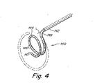
図2乃至図4は、本発明の一実施例に係る末端部の先端アッセンブリを示している。本実施例によれば、先端アッセンブリ140の基端部142は、シャフト110の長さ方向軸に対して約90度の曲がり部148と、これに続いて形成された弧状湾曲末端部144と、を備えている。図2乃至図4に表される実施例では、約90度の曲がり部148が固定され、即ち、先端アッセンブリ140の基端部142に永久的に形成され、それにより、約90度の曲がり部148が体温でその形状を維持するようにする。他の実施例では、約90度の曲がり部148が作働的であってもよく、即ち、図21に関連して更に後述されるように、ハンドル120上のアクチュエータ122,124の一つに取り付けられた引っ張り又は押しケーブルを介してシャフト110の長さ方向軸(L)に対して約ゼロ度から約90度の間で移動可能であってもよい。
Disposed on the
(Tip assembly)
2-4 illustrate a distal tip assembly according to one embodiment of the present invention. According to this embodiment, the
各実施例では、約90度の曲がり部148を備える先端アッセンブリ140の領域は、シャフト110の長さ方向軸(L)に対して湾曲した位置に偏倚されるのが好ましいが、偏倚の度合いは変更されてもよい。詳しくは、固定式曲がり部を特徴とする実施例では、曲がり部148は、先端アッセンブリ140の基端部142内に約90度の角度で永久的に形成され、それにより、例えば、シース/拡張器の使用により容器内に導入するため直線状にすることができる一方で、先端アッセンブリ140の末端部144は、シャフト110の長さ方向軸(L)に略垂直な平面内に載るためその拘束されない状態にスプリングバックする。作動式曲がり部を特徴とする実施例では、僅かな量、例えば数度の曲がり部だけが、先端アッセンブリ140の基端部142に永久的に形成される。先端アッセンブリ140の基端部142内の曲がり部のこの僅かな量は、先端アッセンブリ140の末端部144が、より完全に後述されるように、シャフト110の長さ方向軸(L)に対して所定の方向に曲がることを確実にするのに十分である。しかし、全ての実施例において、先端アッセンブリ140の末端部144は、既知の制御された態様で先端アッセンブリ140の末端部144の曲率半径における増加及び/又は減少を容易にするため弧状形状に永久的に偏倚されている。
In each embodiment, the region of the
先端アッセンブリ140の弧状湾曲末端部144上に配置されているものは、末端部144に沿って均一に間隔を隔てた複数のリング形状電極146と、末端の先端電極147と、である。先端アッセンブリ140の末端部144上に均一に間隔を隔てているものとして示されているが、電極146は、対をなしてグループを形成してもよく、一つの対の各電極の間の距離は、隣接する対の電極の間の距離よりも近い。例えば、各々のリング電極は、長さにして約1mmであってもよく、電極の対は中心で約2mm間隔を隔てており、隣接する対の電極同士は、約8mmだけ間隔を隔てている。更には、図2に示される電極16は、先端アッセンブリ140の末端部144の表面に従う低プロフィールのリング電極であるものとして示されているが、それらは、プロフィールが隆起されてもよい。実際、詳細が更に後述されるように、本発明の実施例は、心臓内又は心外膜のマッピング及び/又は除去処置で使用するのに適している任意種類の電極を用いて使用することができる。本発明は、先端アッセンブリ140の末端部144上の電極の数、構成又は配置に限定されないからである。
Disposed on the arcuate curved
本発明の実施例によれば、先端アッセンブリ140は、例えばPEBAX等のエラストマー又はポリマーの熱力学的生体適合性材料から作られてもよい。この材料は、可撓性シャフト110の末端部112に結合されている。この可撓性シャフトも、エラストマー又はポリマーの熱力学的生体適合性材料から作ることができる。可撓性シャフト110及び先端アッセンブリ140を形成するため使用することができる材料の例は、当該技術分野で周知されており、例えば、共有譲渡された米国特許番号5,383,852、5,462,527、及び、5,611,777号に記載されている。これらの文献は、ここで参照したことでそれらの全体が本願に組み込まれる。
According to embodiments of the present invention, the
本発明の一実施例によれば、可撓性シャフト110は、先端アッセンブリ140の基端部142を形成するため使用される材料よりも堅い材料から作られてもよく、先端アッセンブリ140は、様々に異なる度合いの堅さを有する様々な生体適合性材料から形成することができる。例えば、一実施例では、可撓性シャフト110は、約60ショアDの硬度を有する材料から作られ、先端アッセンブリの基端部142は、約45〜50ショアDの硬度を有する材料から作られ、弧状湾曲末端部144は、約40ショアDの硬度を有する材料から作られる。シャフト110の増大した堅さは、ハンドル120に印加された圧力がより直接的に先端アッセンブリ140に移行されることを可能にする。更には、先端アッセンブリ140の基端部142の中間堅さは、先端アッセンブリ140(更に後述される)の移動(即ち操舵)を可能にすると共に、ハンドル120に印加された圧力が、先端アッセンブリ140の末端部144を心臓内箇所に対して緊密に押し付けるように先端アッセンブリ140の末端部144へとシャフト110を介して移行されることを確実なものとする。そのように強化された接触は、マッピング及び除去処置の両方において有利である。先端アッセンブリ140の末端部133が形成される材料の相対的可撓性は、先端アッセンブリ140の弧状湾曲された末端部144の直径を、ハンドル120上のアクチュエータ122,124のうち一つの操作を介して変更(増加又は減少)させることを可能にする。別の実施例では、可撓性シャフト110は、先端アッセンブリの基端部142と同じ硬度、例えば、45050ショアDを有する材料から作られるが、可撓性シャフト110は、より大きな直径を持ち、かくして、基端部142よりも堅くなっている。
According to one embodiment of the present invention, the
心臓内箇所との接触を更に強化するため、先端アッセンブリ140の基端部142は、約90度の曲がり部148の前方(即ち基端側)で、例えば、外側剛性管(図示せず)を用いて堅くすることができる。例えば、先端アッセンブリ140が、約90度の固定式曲がり部を備える場合、約90度の曲がり部148を形成する材料を、末端部144が形成される材料よりも十分に堅くして、心臓内箇所又は心外膜箇所との接触を更に強化することができる。
To further enhance contact with the intracardiac location, the
本発明の実施例は任意の特定の長さに限定されるものではないが、本発明の一実施例では、可撓性シャフトの長さは、約1mであり、先端アッセンブリの基端部140の長さは約4.5cmであり、先端アッセンブリの末端部144の長さは約6.5cmであり、約90度の曲がり部の長さは約0.7cmである。勿論、カテーテルの異なる部分の長さを、関心のある心臓内箇所又は心臓外箇所に応じて変えることができることが理解されるべきである。
While embodiments of the present invention are not limited to any particular length, in one embodiment of the present invention, the length of the flexible shaft is approximately 1 meter and the
図3に示されるように、先端アッセンブリ140は、シャフト110の長さ方向軸に垂直な1つ以上の方向で移動可能(即ち、操舵可能)とすることができる。例えば、図3の実施例に示されるように、先端アッセンブリ140は、ハンドル120(図1)上のアクチュエータ122,124の一つの操作を介してシャフトの長さ方向軸に対して2つの相反する方向(Z方向として示される)に運動することを可能としている。他の実施例では、先端アッセンブリは、単一の方向(例えば、正のZ方向)のみに移動されてもよく、又は、多数の異なる方向(例えば、正及び負のZ方向、及び、正及び負のY方向)に移動されてもよい。
As shown in FIG. 3, the
図3にも示されるように、本発明の一態様によれば、先端アッセンブリ140の弧状湾曲末端部144の曲率半径(又は直径)を、第1の直径D1から第2の直径D2まで変化させることができる。好ましくは、先端アッセンブリ140の弧状湾曲末端部144の曲率半径を、ハンドル120上に配置されたアクチュエータ122,124の一つの操作を介して増減することができる。先端アッセンブリ140の弧状湾曲末端部144の曲率半径の増加及び減少の両方を行うこの能力は、単一の先端アッセンブリ140を、幅広い様々な用途で使用することを可能にし、幅広い様々な患者(大人又は大型動物から子供又は小型動物まで)に関して使用することを可能にする。患者や特定の医療処置の要求に適合するように様々に異なる直径へと調整することができるからである。それは、径方向外側の力又は径方向内側の力を、心臓内箇所又は心臓外箇所に印加することも可能にする。
As shown also in FIG. 3, according to one aspect of the present invention, the radius of curvature (or diameter) of the arcuate
本発明の一実施例によれば、先端アッセンブリの弧状湾曲末端部の直径は、載置状態(先端アッセンブリ140の末端部144の曲率半径を制御するアクチュエータ122,124のニュートラル位置に対応する)で約20mmであるが、アクチュエータ122,124の一つの操作を介して約5mmの直径へと減少させることができ、約50mmの直径へと増加させることができる。本実施例によれば、約20mmの直径は、図2及び図3に示された、おおよそ閉じた円に対応している。約50mmの直径は、図3の破線に示されるように、半円におおよそ対応しており、約5mmの直径は、図4に示されるように、1つ以上の完全な円に対応している(即ち、末端部のらせん形態)。本発明は、先端アッセンブリ140の末端部144の任意の特定の直径に限定されるものではないが、これらの寸法は、カテーテル100が、焦点トリガーが存在し得る血管、例えば肺静脈に関連したマッピング及び/又は除去処置で使用するのに十分に適合することを可能にする。例えば、約5乃至50mmの直径は、先端アッセンブリを、心臓不整脈のための焦点トリガーが頻繁に遭遇し得るところの肺静脈の小口に関連したマッピング及び/又は除去処置のため使用することを可能にする。これらの寸法は、大きな若しくは小さい、人間若しくは動物のいずれかで、幅広く異なる様々な処置のために、単一の先端アッセンブリ140を使用することを可能にする。先端アッセンブリの弧状湾曲した末端部の直径のための上述した寸法が、指摘された直径の半分である曲率半径に対応する(即ち、50mmの直径が25mmの曲率半径に相当する等)ことが理解されるべきである。
According to one embodiment of the present invention, the diameter of the arcuate curved end of the tip assembly is in the resting state (corresponding to the neutral position of the
図3に関連して説明された先端アッセンブリ140の末端部144の曲率半径は、増減されることができるのが好ましいが、本発明は、それに限定されるものではない。例えば、幾つかの実施例では、曲率半径は、第1の方向にのみ変更(例えば、増加)可能であり、他の実施例では、曲率半径は、第2の方向にのみ変更(例えば、減少)可能である。しかし、上述された実施例の各々において、先端アッセンブリ140の末端部144は、曲率半径の増加及び/又は減少が既知の制御された態様で達成されるように、その載置状態で弧状形状へと永久的に偏倚されるのが好ましい。
先端アッセンブリの操舵及び制御
図11は、図2の末端部の先端アッセンブリ140の拡大端面図である。図11に示されるように、本発明の一実施例では、先端アッセンブリ140の末端部144は、一対のケーブル1110a及び1110bを備え、該ケーブルを、先端アッセンブリの末端部144の曲率半径(又は直径)を第1の直径から第2の直径へと変化させるため使用することができる。図11に示された実施例では、先端アッセンブリは、中央管腔1125や、該中央管腔1125の回りに配置された4つの同軸管腔1128a〜dを始めとした、複数の管腔を備えるコア1120を備えている。中央管腔1125は、先端アッセンブリ140の末端部144に沿って配置された各々の電極146、147に取り付けられた1つ以上の導電ワイヤ(図11には図示せず)を保持するため使用されている。4つの同軸管腔1128a〜dは、ケーブルを保持するため使用されてもよい。該ケーブルは、シャフト110に対して先端アッセンブリ140の配位を制御すると共に、先端アッセンブリ140の末端部144の曲率半径を制御する。図11に示されるように、2つのケーブル1110a及び110bは、先端アッセンブリ140の末端部144の長さに沿って延在し、2つの他のケーブル(図示せず)は、末端部144の前で終わっている。図11に示された実施例では、2つのケーブル1110a及び1110bの端部は、一緒に結合され、先端アッセンブリ140の最末端部に隣接してエポキシが注入される。本実施例では、ケーブル1110a及び1110bは、先端アッセンブリ140の末端部144の曲率半径を制御するため使用される。
Although the radius of curvature of the
Tip Assembly Steering and Control FIG. 11 is an enlarged end view of the
先端アッセンブリが、複数の管腔1125及び1128a〜dを有するコア1120を備えるものとして説明されたが、先端アッセンブリを他の方法で構成することもできることが理解されるべきである。例えば、米国特許番号5,383,852、5,462,527、及び、5,611,777号は、カテーテルの末端部のための代替構成を記載しており、その一部は、電極ワイヤ及び引っ張りケーブルの両方を保持する中央管腔を備えている。本発明は、任意の特定の構成に限定されるものではないので、末端部の先端アッセンブリの代替構成を、本発明の実施例で使用することもできる。
Although the tip assembly has been described as comprising a
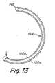
図12及び図13は、先端アッセンブリ140の末端部144の曲率半径を、ハンドル120(図1)上の1つ以上のアクチュエータ122,124に取り付けられたケーブル1110a及び1110bの操作を介して如何に変化させることができるかを示している。図示の実施例では、ケーブル1110a及び1110bは、例えば、ステンレス鋼製ワイヤ又は他の任意の適切な材料から形成することができる引っ張りケーブルである。カテーテル100が、大きな磁場が存在し得る環境、例えば、MRIチャンバー中で使用されるべき場合、ケーブル(実際には、電極146、147)の各々は、非磁性材料から作られてもよい。例えば、電極は、例えば、プラチナ、銀、又は、金等の導電性非磁性材料から作られてもよく、ケーブルは、例えば、カーボンファイバー、又は、KEVLAR(R)、又は、多数の超高分子重ポリエチレンフィラメント等の複合材料から作られてもよい。ケーブル1110a及び1110bは、押しケーブルとして使用されてもよいが、押しケーブルの使用は、一般に、より剛性であることを必要とし、しばしば、圧縮ではなく張力の下で作動的である引きケーブルに対して要求されるものよりも大きな直径のケーブルを必要とすることが理解されるべきである。一例として、引きケーブルの直径は、0.0076乃至0.01cm(0.003乃至0.004インチ)の範囲にあり得る。
FIGS. 12 and 13 show how the radius of curvature of the
図12及び図13に示されるように、ケーブル1110bに印加された張力は、先端アッセンブリ140の末端部144の曲率直径(及びこれに対応するケーブル1110aの緩み)の減少を生じさせ、ケーブル1110aに印加された張力は、先端アッセンブリ140のマッピング端部14の曲率直径の増大を生じさせる。
As shown in FIGS. 12 and 13, the tension applied to the
図14は、以下の図5乃至図10に関して説明されたジグのうち任意の一つを用いて成形する前の、仕上げカテーテル100の末端部の側面図である。本発明の一実施例によれば、先端アッセンブリ140は、一緒にシャフト110に結合された幾つかの異なる区分から形成されてもよい。先端アッセンブリの区分形成は、様々な区分の直径及び堅さのより大きな制御を可能にする。図14に示されるように、これらの区分は、可撓性シャフト110に結合された基端区分1420と、シャフト110に対して約90度曲がるように形成され、該基端区分に結合された中間区分1480と、該中間区分1480に結合され、複数の電極と末端の先端即ちキャップ電極147とを備える末端区分1440と、を備えていてもよい。
FIG. 14 is a side view of the distal end of the finishing
図15は、図14のライン15−15に沿って取られた図14の末端の先端アッセンブリ140の断面図である。本発明の一実施例によれば、先端アッセンブリ140は、管状基端区分1420と、シャフト110と同軸に整列される管状末端区分1440と、備える。基端区分1420と、末端区分1440との間には、シャフト110に対して約90度曲がるように形成されうる中間区分1480が形成されている。図示のように、一実施例では、基端区分1420は、シャフト110と略同じ外径を持ち、末端区分144と中間区分1480とは、略同じ外径を持つことができるが、基端区分1420及びシャフト110よりも僅かに小さい直径を持ち得る。他の実施例では、先端アッセンブリ140を形成する様々な区分は、シャフト110と同じ外径を持ち得る。
15 is a cross-sectional view of the
図示の実施例では、先端アッセンブリ140の末端区分1440は、シャフト110や区分1420,1440及び1480と同軸に整列した末端部即ちキャップ電極147で終わっている。ねじ形成カラー1520は、電極キャップ147を維持するため末端区分1440の末端部に固定されている。他の実施例は、ねじ形成カラー1520や、末端部即ちキャップ電極147を備える必要はなく、例えば、その代わりに、非伝導キャップを利用することができることが理解されるべきである。
In the illustrated embodiment, the
シャフト110は、ハンドル120の末端部からシャフト110の長さ分、延在する単一の管腔1525を備えていてもよい。単一の管腔1525は、引っ張りケーブル1128a〜dや電極ワイヤ1510を収容するため使用されてもよい。各々の引っ張りケーブル及び各電極ワイヤは、シースを備えるのが好ましい。
The
先端アッセンブリ140の電気的部分は、末端部即ちキャップ電極147と共に複数の間隔を隔てたリング式電極を備えていてもよい。電極は、心電図操作者により使用される遠隔記録装置160(図1)に心臓の電位に関する信号情報を提供する。リング式電極146とキャップ電極147とは、各々の信号ワイヤ1510に電気的に接続される。信号ワイヤ1510は、図15、図16及び図17に示されるように、各々の電極146、147に取り付けられる、基端区分1420、中間区分1480及び末端区分1440の各々において中央管腔1125を通りコア1120の長さを通って回送される。信号ワイヤ1510は、互いから電気的に絶縁されるのが好ましく、これにより、図示のように単一管腔を全て分かち合う。信号ワイヤ1510は、ハンドル120を通ってコネクター130へと基端側に延在する。該コネクター130は、電極146及び147を、容易に記録装置160に電気的に連結することを可能にする。図示の実施例では、先端アッセンブリ140の長さのほとんどを延在する2つの引っ張りケーブル1110a及び1110bは、末端区分1440の曲率半径を制御するため使用される。他の2つの引っ張りケーブル1110c及び1110dは、シャフト110の長さ方向軸(L)に垂直な平面内で先端アッセンブリ140の曲がりを制御するため使用される(図14参照)。図15,図16及び図17に示されるように、引っ張りケーブル1110c及び1110dは、中間区分1480の基端側で終わっている。一実施例では、引っ張りケーブル1110c及び1110dの各々は、任意の適切な材料から作ることができ、引っ張りケーブルが収容されている管腔1128c及び1128dよりも直径が大きいボール1530内で終わっている。例えば、引っ張りケーブル1110c及び1110dの各々は、ボール(図示せず)内の孔を通って通過されてもよく、ケーブルが緩くなることを防止するため端部が縛り上げられる。ケーブル1110c及び1110dを終結させる他の方法は、前述した特許文献に記載されており、例えば、ケーブル1110c及び1110dの端部を基端区分1420の末端部で一緒に縛り上げることによりなされる。
The electrical portion of the
シャフト110の長さ方向軸に垂直で且つ引っ張りケーブル1110c及び1110dにより提供された運動の他の平面に垂直である平面内で先端アッセンブリ140の曲がりを制御するため、追加の対の引っ張りケーブルを提供することもできることが認められるべきである。かくして、引っ張りケーブルの数及びハンドル120上に配置されたアクチュエータの数に応じて、先端アッセンブリ140の末端部の曲率半径を増加させたり減少させたりすることができ、先端アッセンブリ140の配位を、シャフトの長さ方向軸に垂直である2つの直交平面(例えば、Y平面及びZ平面)の各々で2つの異なる方向に変えることができる。
An additional pair of tension cables is provided to control the bending of the
基端区分1420は、電極ワイヤ1510の全てを中間区分1480と末端区分1440とに通過させ、引っ張りケーブル1110a及び1110bを通すための中央管腔1125を備えている。基端区分1440は、基端区分1420の長さを通してシャフト110の管腔1525から引っ張りケーブル1110c及び1110dを通過させる2つの基端ケーブル管腔1128c及び1128dを更に備える。基端ケーブル管腔1128c及び1128dは、基端区分1420の軸方向のねじれを減少させるため各々の補強ワイヤ1710(図17)を備えることができる。基端区分1420は、基端区分144をシャフト110の末端部内でシャフトの末端部に嵌合することができるように直径が減少した基端部を備えている。
The
中間区分1480は、基端区分1420の末端部及び末端区分1440の基端部に加熱結合される。中間区分1480は、基端区分及び末端区分の内部に入れ子式にピッタリ入ることができるように2つの減少した直径の端部を備える。中間区分1480は、2つのケーブル1128a及び1128bと、中央管腔1125と、を備える。追加の管腔が後述されるように、備えられてもよい。中央の基端区分管腔1125からの引っ張りケーブル1110a及び1110bは、基端区分1420の中央管腔1125の末端部を通過した点で、外側に配置されたケーブル管腔1128a及び1128bへと各々回送される。引っ張りケーブル1110a及び1110bが径方向に移動可能となるように、小さな遷移空間が、中間区分の管腔と基端区分の管腔との間に設けられている。
末端区分1440は、中間区分1480の末端部に加熱結合され、中間区分1480と略同じ外径を有する。中間区分1480の末端部は、2つの区分の間に滑らかな遷移を提供するため末端区分1440内に引っ込められている。末端区分1440は、2つのケーブル管腔1128a及び1128bと、中央管腔1125と、を更に備える。末端区分1440は、例えば、摺動電極用の制御ワイヤを収容するため、洗浄ラインを収容するため、位置測定センサー用のワイヤを収容するため等で、使用することができる追加の管腔(図16に示される)を更に備えていてもよい。外側に配置されたケーブル管腔1128a及び1128bから出る引っ張りケーブル1110a及び1110bの端部は、一緒に結合され、及び/又は、エポキシが注入されてもよい。中央管腔1125からの電極ワイヤ1510は、図15A及び図16に示されるように、コア1120内の径方向アパーチャを通して供給され、リング電極146の下側表面上に半田付け又は溶接される(又は、伝導エポキシで結合される)。末端部又はキャップ電極のためのワイヤは、中央管腔1125を通して供給され、キャップ電極147上に半田付けされ、溶接され、又は、エポキシ接着されてもよい。
図15に示される実施例では、複数のリング電極146の各々は、低プロフィールを提供するため末端区分の外側周囲表面内に引っ込められている。しかし、例えば、除去処置等、幾つかの処置のために、例えば、図15Aに示され、図16の破線に示されるように、1つ以上の電極1546の外側表面を、末端区分の外側周囲表面を超えて突出させることが好ましい。本発明は、任意の特定種類や電極の構成に限定されるものではないので、様々な種類の電極を、図15に表される先端アッセンブリで使用することができることが理解されるべきである。
In the embodiment shown in FIG. 15, each of the plurality of
先端アッセンブリのシャフト、基端区分、中間区分及び末端区分内に引っ張りケーブルを配置し、固定するため、様々な形態を使用することができる。一般には、曲げモーメントを増大させるため、引っ張りケーブルを該ケーブルにより制御される区分の外側周囲に可能な限り接近させて配送するのが好ましい。この理由のため、基端区分及び末端区分の両方のための制御ケーブルは、外側管腔、即ち管腔1128c、1128d、管腔1128a、1128bに差し向けられる。しかし、ケーブルにより制御される区分に到達する前に、該ケーブルは、カテーテルのより多くの末端区分の運動を制御するケーブルの操作がカテーテルのより多くの基端区分の配位に影響を及ぼさないように、例えば、中央管腔1125内に、中央に配設されるのが好ましい。図示の構成は、製造の容易さ及び機能の観点から最適な構成であることが見出された。しかし、他の構成を使用することもできる。例えば、引っ張りケーブルは、独占的に外側管腔を通って、基端区分、中間区分及び末端区分を通して、通されることができる。先端アッセンブリ140内の引っ張りケーブルの他の構成例は、前述の米国特許番号5,383,852、5,462,527、及び、5,611,777号に記載されている。
Various configurations can be used to place and secure the pull cable within the shaft, proximal section, middle section and distal section of the distal assembly. In general, in order to increase the bending moment, it is preferable to deliver the pull cable as close as possible to the outer periphery of the section controlled by the cable. For this reason, control cables for both the proximal and distal segments are directed to the outer lumens, namely
本発明の一実施例によれば、先端アッセンブリ140の末端部155の制御は、超弾性材料と共に、個々の引っ張りケーブルを使用して提供されてもよい。超弾性材料は、実質的な変形を受けた後、その元の位置に戻るように、「スプリングバック効果」を示す任意材料とすることができる。超弾性材料は、金属合金又は金属を含む化合物から形成されてもよく、一例では、ステンレス鋼よりも約十倍も大きい弾性を持つことができる。任意の超弾性材料を、本実施例に従って使用することができることが理解されるべきであるが、一例では、超弾性ワイヤが使用される。
According to one embodiment of the present invention, control of the distal end 155 of the
使用可能な一例としての超弾性材料は、ニッケル及びチタンを含む化合物である。特に、ニチノール材料を使用することができる。ニチノールは、ほとんど等しい量のニッケル
及びチタンの混合物を含み、形状記憶特性及び超弾性特性を示す、中間材料のファミリーである。ニチノールは、特定の形状に設定することができ、変形後にその形状に戻り、即ちスプリングバックする。超弾性ワイヤの所望の非変形形状を設定するため、所望の形状にワイヤを拘束し、適切な熱処理を加えてもよい。例えば、カテーテル100の先端アッセンブリ140の末端部144は、図5乃至図10に関して説明されたジグ等のジグ内に配置され、超弾性ワイヤの形状が設定されるまで、加熱されてもよい。1〜5分の間に400〜500℃の温度を加えるのが当該形状を設定する上で十分となる。
One example superelastic material that can be used is a compound containing nickel and titanium. In particular, a nitinol material can be used. Nitinol is a family of intermediate materials that contain nearly equal amounts of a mixture of nickel and titanium and exhibit shape memory and superelastic properties. Nitinol can be set in a specific shape and after deformation it will return to that shape, ie spring back. In order to set the desired non-deformed shape of the superelastic wire, the wire may be constrained to the desired shape and appropriate heat treatment may be applied. For example, the
ニチノールは、体温で、その最適な超弾性挙動を示し、よって、身体内に挿入されたカテーテルで使用するのに十分に適している。ニチノールは、カテーテル内に使用するのにも非常に適している。それは、非磁性であり、よって、MRI画像形成と干渉せず、ステンレス鋼に比較可能な透視画像を形成する。 Nitinol exhibits its optimal superelastic behavior at body temperature and is therefore well suited for use with catheters inserted into the body. Nitinol is also very suitable for use in catheters. It is non-magnetic and thus forms a perspective image comparable to stainless steel without interfering with MRI imaging.
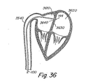
図38は、本発明の一実施例に従って実行される図2の末端部の先端アッセンブリ140の拡大立面図である。図38に示されるように、先端アッセンブリ140の末端部144は、第1の半径から第2の半径まで先端アッセンブリの曲率半径を変化させるためケーブル1110aと共に使用することができる超弾性ワイヤ3810を備えている。図38に示されるように、引っ張りケーブル1110a及び超弾性ワイヤ3810は、管腔1128a及び1128bを通って先端アッセンブリ140の末端部144の長さに沿って各々延在し、一緒に結合され、先端アッセンブリ140の最末端部に隣接してエポキシが注入される。
38 is an enlarged elevation view of the
多数の変更が、図38に示された先端アッセンブリ140の末端部144に関して可能となる。例えば、超弾性ワイヤ3810が管腔1128bを通って4先端アッセンブリ140の末端部144の長さに沿って延在して示されているが、超弾性ワイヤ3810が、カテーテル100の他の部分に配置されてもよい。例えば、超弾性ワイヤ3810は、中央管腔1125又は別の管腔内に収容されてもよく、又は、先端アッセンブリ140のコア1120内に埋め込まれてもよい。更には、超弾性ワイヤ3810が、先端アッセンブリ140の最末端部に固定され、ケーブル1110aを用いて一緒に結合されて示されているが、この構成は、必ずしも必要ではない。上述のように、ワイヤは、一旦変形された場合その元の形状に戻る傾向を有するように「スプリングバック効果」を示す材料から形成されるので、超弾性ワイヤ3810は、固定される必要はない。更には、超弾性ワイヤ3810は、先端アッセンブリ140の末端部144で代わりに独立して固定することができるケーブル1110aに結合される必要もない。
Numerous changes are possible with respect to the
超弾性ワイヤ3810は、先端アッセンブリ140の末端部144を所望の弧状形状に偏倚するのに十分であるようにカテーテル100の任意部分を通って延在してもよい。例えば、ワイヤは、カテーテル100の制御ハンドル120で始まってもよく、又は、より末端の位置で始まってもよい。例えば、超弾性ワイヤ3810は、弧状形状を形成し得るカテーテル100の当該部分(即ち、先端アッセンブリ140の末端部144)だけ占めてもよい。更には、超弾性ワイヤ3810は、カテーテル10を更なる配位に偏倚させるため、カテーテル100の別の部分を通って延在してもよい。カテーテルの様々な部分で異なる仕方でカテーテル100を偏倚させるための超弾性ワイヤ3810の使用は、更に後述されよう。
The
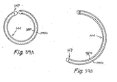
図39A及び図39Bは、先端アッセンブリ140の末端部144の曲率半径を、ハンドル120(図1)上のアクチュエータ122,124に固定されるケーブル1110aの操作を介して如何に変化させることができるかを示している。曲率半径を変化させるため一つだけの引っ張りワイヤが使用されるので、一つだけの引っ張りワイヤが、本実施例に係るアクチュエータ122又は124に固定されることが理解されるべきである。図39Aに示されるように、超弾性ワイヤ3810は、弧状湾曲を形成するため偏倚されており、張力が引っ張りケーブル1110aに印加されないときには、先端アッセンブリ140の末端部144が、かかる形状を呈するようにさせている。張力がケーブル1110aに印加されたとき、図39Bに示されるように、先端アッセンブリ140の末端部144の曲率半径が増大する。
39A and 39B show how the radius of curvature of the
引っ張りケーブル及び超弾性ワイヤの位置が逆転された場合、反対の効果が生じる。例えば、図41A及び図41Bは、末端部144の弧状湾曲の外側部分に配置された超弾性ワイヤ3810を示し、かくして、弧状湾曲の内側部分に配置された引っ張りケーブル1110bよりも大きい曲率半径を有することを示している。図41Aに示されるように、超弾性ワイヤ3810は、弧状湾曲を形成するように偏倚され、張力が引っ張りケーブル1110bに印加されないときには、先端アッセンブリ140の末端部144が、かかる形状を呈するようにさせている。張力がケーブル1110bに印加されたとき、図41Bに示されるように、先端アッセンブリ140の末端部144の曲率半径が減少する。
The opposite effect occurs when the position of the pull cable and superelastic wire is reversed. For example, FIGS. 41A and 41B show a
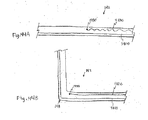
図43A及び図43Bは、図41A及び図41Bに示されるものに類似した形態を示している。しかし、弧状湾曲で偏倚されているのではなく、超弾性ワイヤ3810が直線的に偏倚され、張力が引っ張りケーブル1110bに印加されないとき先端アッセンブリ140の末端部144が直線配位を呈するようにさせる(図43A参照)。張力がケーブル1110bに印加されたとき、図43Bに示されるように、先端アッセンブリ140の末端部144の曲率半径が減少し、先端アッセンブリ140の末端部144が弧状湾曲を呈するようにさせる。
43A and 43B show a configuration similar to that shown in FIGS. 41A and 41B. However, rather than being biased with an arcuate curvature, the
本発明の別の実施例によれば、接着剤がカテーテル100に導入されてもよく(図1)、それがカテーテル100に偏倚を分与し、又は、カテーテル100の一部分を特定の位置又は形状に保持しようとするように、一定形態で硬化されてもよい。例えば、接着剤は、例えば、注射器を用いてカテーテル100の管腔内に注入されてもよく、カテーテル10の一部分が、図5乃至図10に関連して説明されたジグ等のジグ内に配置されてもよい。該ジグは、接着剤が硬化して、硬化された接着剤でカテーテル100が特定の配位に偏倚される間に、カテーテル100を所望の位置に保持する。本発明の別の態様によれば、接着剤は、先端アッセンブリ140の制御を提供するため引っ張りケーブルと関連して使用されてもよい(図1)。エポキシ及びシリコンは、本実施例に従って使用することができる2つの例示的な接着剤である。カテーテル材料と適合し、硬化されたとき偏倚を分与するか又はそれらの形状を保持しようとする他の接着剤も使用することができる。偏倚を提供するため接着剤を含むカテーテル100の様々な形態を以下に説明する。
According to another embodiment of the present invention, an adhesive may be introduced into the catheter 100 (FIG. 1), which imparts a bias to the
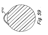
図45は、本発明の本実施例に従って実行される図2の末端部の先端アッセンブリ140の拡大立面図である。図45に示されるように、先端アッセンブリ140の末端部144は、弧状形状に硬化された管腔1128b内に接着剤4510を備えている。ケーブル1110aで使用されるとき、接着剤4510が、後述されるように、第1の半径から第2の半径まで先端アッセンブリの曲率半径を変化させるため使用されてもよい。
45 is an enlarged elevational view of the
接着剤4510は、先端アッセンブリ140の末端部144の長さに沿って管腔1128bを通って延在するように示されているが、接着剤4510は、カテーテル100の他の部分に配置されてもよいことが理解されるべきである。例えば、接着剤4510は、中央管腔1125又は先端アッセンブリ140の別の管腔内に配置されてもよい。更には、接着剤4510は、先端アッセンブリ140の末端部144を所望の弧状形状に偏倚させるため十分であるようにカテーテル100の任意部分を通って延在してもよい。例えば、接着剤4510は、カテーテル100の制御ハンドル120から延在してもよく、又は、より末端位置で始まってもよく、又は、弧状形状を形成することができるカテーテル100の当該部分のみを占めていてもよい(即ち、先端アッセンブリ140の末端部144)。更に加えて、接着剤4510は、カテーテル10の別の部分を通して延在してもよく、カテーテル100を追加の配位に偏倚させるように硬化されてもよい。カテーテル100を該カテーテルの異なる部分で異なる仕方で偏倚させるための接着剤4510の使用法が、更に詳細に後述される。
While adhesive 4510 is shown extending through
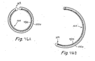
図46A及び図46Bは、先端アッセンブリ140の末端部144の曲率半径が、ハンドル120(図1)上のアクチュエータ122,124に取り付けられたケーブル1110aの操作を介して如何に変えることができるかを示している。一つだけの引っ張りワイヤが、曲率半径を変化させるため使用され、一つだけの引っ張りケーブルが本実施例に従ってアクチュエータ122又は124に取り付けられることが理解されるべきである。図46Aに示されるように、接着剤4510は、弧状湾曲を形成するため偏倚され、張力が引っ張りケーブル1110aに印加されないとき、先端アッセンブリ140の末端部144が、かかる形状を呈するようにさせる。張力がケーブル1110aに印加されたとき、図46Bに示されるように、先端アッセンブリ140の末端部144の曲率半径が増大する。
46A and 46B show how the radius of curvature of the
引っ張りケーブル及び超弾性ワイヤの位置が逆転された場合、反対の効果が生じる。例えば、図48A及び図48Bは、末端部144の弧状湾曲の外側部分に配置された接着剤4510を示し、かくして、弧状湾曲の内側部分に配置された引っ張りワイヤ1110bよりも大きい曲率半径を有することを示している。図48Aに示されるように、接着剤4510は、弧状湾曲を形成するように偏倚され、張力が引っ張りケーブル1110bに印加されないときには、先端アッセンブリ140の末端部144が、かかる形状を呈するようにさせている。張力がケーブル1110bに印加されたとき、図48Bに示されるように、先端アッセンブリ140の末端部144の曲率半径が減少する。
The opposite effect occurs when the position of the pull cable and superelastic wire is reversed. For example, FIGS. 48A and 48B show an adhesive 4510 disposed on the outer portion of the arcuate curve of the
図50A及び図50Bは、図48A及び図48Bに示されるものに類似した形態を示している。しかし、弧状湾曲で偏倚されているのではなく、接着剤4510が直線的に偏倚され、張力が引っ張りケーブル1110bに印加されないとき先端アッセンブリ140の末端部144が直線配位を呈するようにさせる(図50A参照)。張力がケーブル1110bに印加されたとき、図50Bに示されるように、先端アッセンブリ140の末端部144の曲率半径が減少し、先端アッセンブリ140の末端部144が弧状湾曲を呈するようにさせる。
50A and 50B show a configuration similar to that shown in FIGS. 48A and 48B. However, rather than being biased in an arcuate curve, the adhesive 4510 is linearly biased so that the
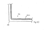
図52及び図53は、引っ張りワイヤが省略された本発明の代替実施例を示している。かくして、接着剤は、カテーテル100の一部分を固定形態に偏倚するため使用される。図52に示されるように、接着剤4510は、先端アッセンブリ140の末端部144に備えられ、末端部144を弧状形状に偏倚させるように硬化されてもよい。図53に示されるように、接着剤は、先端アッセンブリ140の基端部142に追加的に又は代替として備えられ、約90度の曲がり148で基端部142を偏倚させるため硬化され得る。上記したように、図52及び図53における接着剤4510を、カテーテル100上の偏倚をもたらすため、例えば、注射器を介して、カテーテル100の所望の管腔へと導入することができ、これは例えば図5乃至図10のジグ等のジグ内で硬化されてもよい。図52及び図53に示されるように、先端アッセンブリ140の接着剤を提供することは、貯蔵の間又は使用中に湾曲部が緩むことを防止しようとする。
52 and 53 show an alternative embodiment of the present invention in which the pull wire is omitted. Thus, the adhesive is used to bias a portion of the
図65A及び図65Bは、本発明の別の実施例を示し、該実施例では、接着剤が、先端アッセンブリ140の末端部144の弧状湾曲への支持を提供するためカテーテル内部で使用されている。そのような支持を提供するため、接着剤は、カテーテル内に導入され、カテーテルが特定の位置又は形状に維持される間に硬化される。接着剤は、例えば、注射器を用いて、カテーテルの1つ以上の管腔内に注入されてもよく、カテーテルの一部分を、図5乃至図10に関連して説明されたジグ等のジグに配置することができる。ジグは、接着剤が硬化する間にカテーテルを所望の位置に保持する。図65A及び図65Bに示されるように、接着剤6410は、電極ワイヤ又は他のワイヤを含むことができる管腔1128c〜d内に配置される。接着剤6410が管腔1128c〜d内に配置された状態で示されているが、接着剤6410は、中央管腔、又は、引っ張りケーブルにより示されていない別の管腔内に配置されてもよい。接着剤6410は、エポキシ、シリコン、又は、カテーテルが特定の位置にある間にカテーテル内の材料が硬化されるとき、カテーテルを特定の形状に維持しようとする他の材料のいずれであってもよい。
65A and 65B illustrate another embodiment of the present invention in which an adhesive is used inside the catheter to provide support for the arcuate curvature of the
図65Bに示されるように、引っ張りケーブル1110a〜bは、先端アッセンブリ140の基端部144の位置を制御するため使用することができる。図面では、張力が引っ張りケーブル1110bに印加され、引っ張りケーブル1110aには印加されず、それにより、特定の曲率半径を有する弧状湾曲が形成されている。湾曲形状で硬化することができる接着剤6410は、引っ張りケーブルが所望の曲率半径をもたらすことができるように、カテーテル構造に支持を提供する。接着剤6410が無い場合、所望の曲率半径をもたらす引っ張りケーブル1110a〜bの能力は、時間と共に劣化し得る。
作動的曲がり部
上記したように、末端部の先端アッセンブリ140における約90度の曲がり部は、固定されているか(例えば、以下の図5乃至図10に関して詳細に記載された、例えばジグ500、700及び900等のジグの使用で永久的に形成される)、又は、ハンドル120上に配置されたアクチュエータ122、124の使用により作動的である(例えば、カテーテル100のシャフト110の長さ方向軸に対して約0度乃至約90度の間で移動可能である)かのいずれであってもよい。図21及び図21Aは、そのような「作動的曲がり部」を備える本発明の一実施例を示している。
As shown in FIG. 65B, the
As described above, the approximately 90 degree bend in the
図21に示されるように、一実施例では、末端部の先端アッセンブリ140は、基端区分2120と、シャフト110の長さ方向軸に略垂直であるように制御ハンドル120上のアクチュエータ(例えば、アクチュエータ122)に取り付けられた制御ケーブル(図21A)の操作を介して作動的に曲げることができる中間区分2180と、ハンドル120上のアクチュエータ(例えば、アクチュエータ124)に取り付けられた制御ケーブルの操作を介して調整することができる曲率半径を有する末端区分2140と、を備えている。末端区分2140は、末端区分2140の長さに沿って配置された1つ以上の電極146、147を備える。
As shown in FIG. 21, in one embodiment, the
図21のライン21A〜21Aに沿って取られた先端アッセンブリ140の基端区分2120の断面図である図21Aに示されるように、中間区分2180の曲がりを制御するケーブル1110c及び1110dは、基端区分2120の減少した直径の端部の回りに巻き付き、米国特許番号5,383,852号の図12に関して説明されたものに類似した態様で中間区分2128内に引っ込められている単一のケーブルから形成することができる。一般に、ケーブルは、曲がりが生じるべきポイントの直前である先端アッセンブリの部分の回りに巻き付くであろう。本実施例では、ケーブル1110cに印加された張力は、シャフト110の長さ方向軸に垂直である平面内で弧状に湾曲した末端区分2140を配位するように(図21に示されるように)下側方向に先端アッセンブリ140の末端区分2140の曲がりを生じさせ、ケーブル1110dに印加された張力は、シャフトの長さ方向軸に沿ってその位置へと戻るように(図21に示されるように)上側方向に先端アッセンブリ140の末端区分2140の曲がりを生じさせる。ハンドル120を180度回転することができるので、末端区分を反対方向に曲げる能力は不必要となるが、所望ならば提供されてもよい。他の実施例では、単一の制御ワイヤのみを使用することができることが理解されるべきである。
As shown in FIG. 21A, which is a cross-sectional view of the
上記のような作動的湾曲部と適合するため、中間区分2180を形成する材料は、中間区分2180で曲がりが生じるように、シャフト110を形成する材料よりも剛性が少なくあるべきである。好ましくは、中間区分2180及び基端区分2120の配位を各々変えること無く末端区分2140の曲率半径を変化させることを可能にするため、末端区分を形成する材料は中間区分を形成する材料よりも剛性が少ないのがよい。
In order to be compatible with the operative bend as described above, the material forming the
既知の制御された態様で曲がりを容易にするため、中間区分2180は、シャフト110の長さ方向軸(L)に対して数度の曲がりを持つため永久的に偏倚されてもよい。中間区分2180がシャフト110の長さ方向軸(L)から数度永久的に偏倚されているので、ケーブル1110cに印加された張力は、シャフト110の長さ方向軸(L)に対して90度の角度へと、曲がり部の平面内に中間区分2180の曲がりを生じさせる。対向するケーブル、例えば、1110dに印加された張力は、曲がり部の平面内で、シャフト110の長さ方向軸(L)に向かって戻るように中間区分2180の曲がりを生じさせる。中間区分2180が特定の方向にシャフト110の長さ方向軸(L)から数度偏倚されているので、中間区分2180の曲がりは、既知の制御された態様で当該曲がり部と同じ方向に整列された平面内で生じる。中間区分2180が特定の方向に偏倚されていなかったならば、曲がりは任意の方向に発生し得るであろう。
In order to facilitate bending in a known controlled manner, the
先端アッセンブリ142を偏倚させる他の態様も可能である。一実施例では、超弾性ワイヤ3810を使用して先端アッセンブリ140の末端部144の弧状湾曲の制御をもたらすため図39、41及び43に適用された原理を、先端アッセンブリ140の基端部142の90度の曲がり部148の制御をもたらすため適用することができる。図40A及び図40Bは、先端アッセンブリ140の基端部142の曲げ角度を、ハンドル120(図1)上のアクチュエータ122,124に取り付けることができるケーブル110dの操作を介して如何に変化させることができるかを示している。図40Aに示されるように、超弾性ワイヤ3810は、カテーテル100の長さ方向軸に対して約90度の角度(一実施例において)を有する曲がり部を形成するため偏倚され、張力が引っ張りケーブル1110dに印加されないとき、先端アッセンブリ140の基端部142が、かかる形状を呈するようにさせている。張力がケーブル1110dに印加されたとき、図40Bに示されるように、先端アッセンブリ140の基端部142の曲げ角度は減少する。
Other ways of biasing the
引っ張りワイヤ及び超弾性ワイヤの位置が逆転された場合、先端アッセンブリ140の基端部142の曲げ角度は、超弾性ワイヤの偏倚位置から増大することができる。例えば、図42A及び図42Bは、曲がり部に対して基端部142の外側部分に配置された超弾性ワイヤ3810と、内側部に配置された引っ張りケーブル1110cと、を示している。図41Aに示されるように、超弾性ワイヤ3810は、鋭角の曲げ角度をなすように偏倚され、張力が引っ張りケーブル1110cに印加されないとき、先端アッセンブリ140の末端部144が、かかる形状を呈するようにさせている。張力がケーブル1110cに印加されたとき、図42Bに示されるように、基端部142の曲げ角度は約90度まで増大する(一実施例)。
When the positions of the pull and superelastic wires are reversed, the bending angle of the
図44A及び図44Bは、図42A及び図42Bに示されるものに類似した形態を示している。しかし、曲げ角度をなすように偏倚されるのではなく、超弾性ワイヤ3810が直線的に偏倚され、張力が引っ張りケーブル1110cに印加されないとき、先端アッセンブリ140の基端部142が、直線配位を呈するようにさせている(図44A参照)。張力がケーブル1110cに印加されたとき、一実施例では、図44Bに示されるように、基端部142の曲げ角度は約90度まで増大する。曲がり部が約90度まで増大するものとして記載されたが、他の曲げ角度も可能となることが理解されるべきである。
44A and 44B show a configuration similar to that shown in FIGS. 42A and 42B. However, rather than being biased to form a bending angle, when the
接着剤4510を使用して先端アッセンブリ140の末端部144の弧状湾曲の制御をもたらすため図46、48及び50に適用された原理を、先端アッセンブリ140の基端部142の90度の曲がり部148の制御をもたらすため適用することができる。図47A及び図47Bは、先端アッセンブリ140の基端部142の曲げ角度を、ハンドル120(図1)上のアクチュエータ122,124に取り付けることができるケーブル110dの操作を介して如何に変化させることができるかを示している。図47Aに示されるように、接着剤4510は、カテーテル100の長さ方向軸に対して約90度の角度を有する曲がり部を形成するため偏倚され、張力が引っ張りケーブル1110dに印加されないとき、先端アッセンブリ140の基端部142が、かかる形状を呈するようにさせている。張力がケーブル1110dに印加されたとき、図47Bに示されるように、先端アッセンブリ140の基端部142の曲げ角度は減少する。
The principles applied in FIGS. 46, 48 and 50 to provide control of the arcuate curvature of the
引っ張りワイヤ及び接着剤の位置が逆転された場合、先端アッセンブリ140の基端部142の曲げ角度は、接着剤の偏倚位置から増大することができる。例えば、図49A及び図49Bは、曲がり部に対して基端部142の外側部分に配置された接着剤4510と、内側部に配置された引っ張りケーブル1110cと、を示している。図49Aに示されるように、接着剤4510は、鋭角の曲げ角度をなすように偏倚され、張力が引っ張りケーブル1110cに印加されないとき、先端アッセンブリ140の末端部144が、かかる形状を呈するようにさせている。張力がケーブル1110cに印加されたとき、図49Bに示されるように、基端部142の曲げ角度は約90度まで増大する。
When the position of the pull wire and adhesive is reversed, the bending angle of the
図52A及び図51Bは、図49A及び図49Bに示されるものに類似した形態を示している。しかし、曲げ角度をなすように偏倚されるのではなく、接着剤4510が直線的に偏倚され、張力が引っ張りケーブル1110cに印加されないとき、先端アッセンブリ140の基端部142が、直線配位を呈するようにさせている(図51A参照)。張力がケーブル1110cに印加されたとき、図51Bに示されるように、基端部142の曲げ角度は約90度まで増大する。
52A and 51B show a configuration similar to that shown in FIGS. 49A and 49B. However, rather than being biased to form a bend angle, when the adhesive 4510 is linearly biased and tension is not applied to the
図64A及び図64Bは、本発明の別の実施例を示し、該実施例では、接着剤が、先端アッセンブリ140の基端部142の90度の曲がり部148への支持を提供するためカテーテル内部で使用されている。そのような支持を提供するため、接着剤は、カテーテル内に導入され、カテーテルが特定の位置又は形状に維持される間に硬化される。接着剤は、例えば、注射器を用いて、カテーテルの1つ以上の管腔内に注入されてもよく、カテーテルの一部分を、図5乃至図10に関連して説明されたジグ等のジグに配置することができる。ジグは、接着剤が硬化する間にカテーテルを所望の位置に保持する。図64A及び図64Bに示されるように、接着剤6410は、電極ワイヤ又は他のワイヤを含むことができる管腔1128c〜d内に配置される。接着剤6410が管腔1128c〜d内に配置された状態で示されているが、接着剤6410は、中央管腔、又は、引っ張りケーブルにより示されていない別の管腔内に配置されてもよい。接着剤6410は、エポキシ、シリコン、又は、カテーテルが特定の位置にある間にカテーテル内の材料が硬化されるとき、カテーテルを特定の形状に維持しようとする他の材料のいずれであってもよい。
64A and 64B illustrate another embodiment of the present invention in which the adhesive is used to provide support to the 90
図64Bに示されるように、引っ張りケーブル1110c〜dは、先端アッセンブリ140の基端部142の位置を制御するため使用することができる。図面では、張力が引っ張りケーブル1110cに印加され、引っ張りケーブル1110dには印加されず、それにより、約90度の角度を有する曲がり部148が形成されている。曲がった形状で硬化することができる接着剤6410は、引っ張りケーブルが所望の曲げ角度をもたらすことができるように、カテーテル構造に支持を提供する。接着剤6410が無い場合、所望の曲げ角度をもたらす引っ張りケーブル1110c〜dの能力は、時間と共に劣化し得る。超弾性チャンネル
図66〜図72は、本発明の更なる実施例を示しており、該実施例によれば、特定の形態を有するカテーテルの一部分に偏倚を分与するため超弾性チャンネルを使用することができ、これにより、当該一部分は変形後に当該形態にスプリングバックする。一例では、超弾性チャンネルは、カテーテルの管腔の一部分内に組み込まれてもよく、カテーテル部品(例えば、引っ張りケーブル、ワイヤ、又は、流体導管)、又は、そのような多数のカテーテル部品が、該管腔の該一部分を通過することを可能にする間にカテーテルを特定の形態に偏倚させる。別の例では、超弾性チャンネルは、カテーテル内部に組み込まれてもよきが、管腔内には組み込まれなくてもよい。例えば、当該チャンネルは、カテーテルの外側シースの一部をなしてもよく、又は、カテーテル内の多くの構造(例えば、管腔)を少なくとも部分的に覆う内部チャンネルであってもよい。
As shown in FIG. 64B, the
図66〜図67に示される一例では、超弾性チャンネル6620a〜bは、約90度曲げられたものとして説明されるが、90度よりも大きい角度又は小さい角度を有していてもよい曲がり部148を備える、先端アッセンブリ140の一部分に備えられている。チャンネル6620a〜bは、管腔1128a及び1128b内に各々備えられ、先端アッセンブリ140の基端部142における位置6610aから電極146bにおける位置6610bまで延在する。かくして、一例では、チャンネル6620a〜bは、先端アッセンブリ140の基端部142から先端アッセンブリ140の末端部144の一部分まで延在し、湾曲を形成するように偏倚され得る。チャンネル6620a〜bは、管腔1128a〜bそれ自体により適所に保持されてもよく、又は、例えば、各チャンネルと、位置6610a近傍の管腔との間のエポキシを用いて、管腔に接着されてもよい。チャンネル6620a〜bは、位置6610a及び6610bに亘るカテーテルの一部分を偏倚させ、90度の曲がり部148の形状を形成し、変形された後に当該形状にスプリングバックする。かくして、チャンネル6620a〜bは、先端アッセンブリ140において弾性曲げ角度を形成する。しかし、チャンネル6620a〜bは、所望の偏倚又は弾性を達成するため、他の偏倚機構(例えば、ジグ内で加熱)及び/又は弾性機構(例えば、超弾性ワイヤ)と関連して使用することができることが理解されるべきである。
In the example shown in FIGS. 66-67, the superelastic channels 6620a-b are described as being bent about 90 degrees, but bends that may have an angle greater or less than 90 degrees. 148 is provided on a portion of
超弾性チャンネルを使用して先端アッセンブリ140に弾性曲げ角度を達成するため、図66乃至67に示された形状に多数の変形をなすことが可能である。例えば、チャンネル6620a〜bは、本文中に説明された管腔1128a〜dのうち任意のもの又は1つ以上の追加の管腔を占めることができる。更には、2つのチャンネルが占めあれているが、単一のチャンネル又は2つより多くの(例えば、3、4、5以上の)チャンネルを用いることができる。更には、チャンネル6620は、図66乃至67で、位置6610aと6610bとの間に配置されているが、この形態は、単なる例示にしか過ぎず、チャンネル6620は、異なるサイズ又は位置のカテーテルの一部分に亘って延在することができる。オプションで、曲がり部148におけるカテーテルの一部分は、カテーテルの隣接する部分よりも低いデュロメーターを有する材料から形成されてもよい。曲がり部148における領域をより柔らかくすることは、超弾性チャンネルにより分与された偏倚に、より大きな応答の自由度を可能とすることにより、超弾性チャンネルの効果を強化する。
Many variations can be made to the shape shown in FIGS. 66-67 to achieve an elastic bending angle in the
図68乃至図69は、上述された超弾性チャンネルのための一例としての形態を示している。図68は、内側表面直径Di及び外側表面直径Doを有する円柱形状を有する超弾性チャンネル6810を示している。図69は、両内側表面の間の長さLiと、両外側表面の間の長さLoを備える矩形形状を有する超弾性チャンネル6910を示している。一例では、内側表面直径Di又は長さLiは、約0.0025〜約0.028cm(約0.01〜約0.011インチ)であり、外側表面直径Do又は長さLoは、約0.036〜約0.038cm(約0.014〜約0.015インチ)であってもよい。本文中で説明された超弾性チャンネルは、様々な形状を呈してもよく、図68乃至図69に示されたものに限定されないことが認められるべきである。例えば、チャンネルは、スプリング、楕
円形状チューブ、多側面チューブ(五角形又は八角形のチューブ)、又は、別の中空形状として形成されてもよい。超弾性チャンネル6810及び6910は、本文中で説明された一例としての超弾性材料の任意のもの、例えば、ニチノール又は、ニッケル及びチタニウムを含む別の組成分から形成されてもよい。一例では、超弾性チャンネル6810及び6910は、ストリング焼き入れされたステンレス鋼から形成される。
68-69 show an exemplary configuration for the superelastic channel described above. FIG. 68 shows a
引っ張りケーブル6820又は6920は、各々超弾性チャンネル6810及び6910内に配置された状態で示されている。引っ張りケーブルのそれらの各々のチャンネル内の移動を容易にするため、引っ張りケーブル及び/又はチャンネルは、例えばポリテトラフルオロエチレン(テフロン(登録商標))等の低摩擦材料を含んでいてもよい。例えば、図68は、引っ張りケーブル6810の移動を容易にするため、超弾性チャンネル6810の内部に接着された低摩擦コーティング6830を示している。代替例として、チャンネル6810それ自体が低摩擦材料から形成されてもよい。図69は、引っ張りケーブル6920の移動を容易にするため引っ張りケーブル6920の外部に接着された低摩擦コーティング6930を示している。コーティング6930は、引っ張りケーブル6920の全体、又は、チャンネル6910とのみ接触する引っ張りケーブルの一部分のいずれにも形成することができる。代替例として、引っ張りケーブル6920それ自体を、低摩擦材料から、全体的又は部分的に形成することができる。
Pull
引っ張りケーブルが、図68乃至図69に示された超弾性チャンネルを通過して示されているが、本発明は、この点に限定されるものではないことが理解されるべきである。前述されたように、例えばワイヤ又は流体導管等の他のカテーテル部品が超弾性チャンネルを通過してもよい。代替例として、チャンネルは、遙かに大きくてもよく、カテーテルの外側シースの一部を形成してもよく、又は、カテーテル内の多数の構造(例えば、管腔)を覆う内部チャンネルであってもよい。 Although a pull cable is shown through the superelastic channel shown in FIGS. 68-69, it should be understood that the present invention is not limited in this respect. As previously described, other catheter components such as wires or fluid conduits may pass through the superelastic channel. As an alternative, the channel may be much larger and may form part of the outer sheath of the catheter, or an internal channel that covers a number of structures (eg, lumens) within the catheter. Also good.
図70は、カテーテルのボディ内に組み込まれる前の、超弾性チャンネルの一例としての形状を示している。超弾性チャンネル7010は、基端脚部7010aと、末端脚部7010bと、基端脚部及び末端脚部を連結する曲がり部7010cと、を備える。一例では、曲がり部7010cは、約0.64cm(約0.25インチ)の半径を有し、脚部7010a〜bは、60°乃至110°の角度7020(例えば、約80°)をなしているが、他の寸法も可能である。更には、チャンネル7010が略平坦であるものとして示されているが、末端脚部7010bは、湾曲部を持っていてもよい。一例では、そのような湾曲部は、先端アッセンブリ140の末端部144の一部の湾曲部に対応している。超弾性チャンネルの所望の変形されない形状を設定するため、該チャンネルを、所望の形状に拘束し、本願で論じられる超弾性ケーブルに関連して説明されたものに類似した態様で適切な熱処理を加えてもよい。
FIG. 70 shows an exemplary shape of a superelastic channel prior to being incorporated into the catheter body. The super
図66乃至図70の説明は、先端アッセンブリ140において「固定曲がり部」を形成するため超弾性チャンネルの使用を考えているが、超弾性チャンネルを、作動的曲がり部(即ち、アクチュエータの操作を介して制御される曲がり部)に関連して使用することもできる。図71は、曲がり部148の弾性湾曲部を形成するため先端アッセンブリ140の基端部142に備えられた超弾性チャンネル7110であって、曲がり部148の制御された操作を可能にするため引っ張りケーブル1110dが更に備えられている状態を示している。図71の形態は、超弾性チャンネルが超弾性ワイヤとは異なる態様で使用されていることを除いて、図40A〜Bと関連して説明されたものに類似している。図示の超弾性チャンネル7110は、先端アッセンブリ140の一部だけしか占めていないが、代替例として、超弾性チャンネルは、先端アッセンブリ140の端部内に更に延在するか又は該端部へと延在してもよい。引っ張りケーブル1110dを介した図71の曲がり部148の操作は、図40A乃至Bと関連して説明されたのと同じ態様となり得る。
The description of FIGS. 66-70 contemplates the use of a superelastic channel to form a “fixed bend” in the
上述された超弾性チャンネルが、90°の曲がり部148で弾性湾曲部を形成するため使用されているが、本発明は、この点に限定されるものではないことが理解されるべきである。偏倚を分与するのが望まれるカテーテルの他の部分に超弾性チャンネルが備えられてもよい。例えば、図72は、超弾性チャンネル7210が弧状湾曲部内で末端部144を偏倚するため使用される形態を示している。超弾性チャンネル7210は、カテーテルの壁を備えたカテーテルの管腔内に又はカテーテルの内部の他の箇所に組み込まれていてもよい。弧状形状は、該弧状湾曲が引っ張りケーブルを介して操作できないように、図72に示されるように固定式であってもよい。代替例として、曲率半径を制御するように操作可能である引っ張りケーブルを設ける(例えば、湾曲部の内部に管腔内)ことにより、作動的曲がり部を実現することができる。図72の湾曲部の操作は、図39A〜Bに関連して説明されたものと同じ態様でなし得る。
電極形態
上記したように、本発明の実施例は、先端アッセンブリの末端部に沿って配置された電極の特定の構成、型式又は数に限定されるものではない。例えば、本発明の実施例は、例えば図2に示されるように、末端部又はキャップ電極147の有無に関わらず、先端アッセンブリ140の末端部に沿って配置された複数の低プロフィールのリング式電極16を備えていてもよい。代替例として、末端部又はキャップ電極147の有無に関わらず、図15Aに示された電極1546等のように、複数の隆起プロフィールリング式電極を使用することができる。なお代替例として、隆起及び低プロフィール電極の組み合わせを使用することができる。
Although the superelastic channel described above is used to form an elastic curve with a 90 °
Electrode Configuration As noted above, embodiments of the present invention are not limited to a particular configuration, type or number of electrodes disposed along the distal end of the tip assembly. For example, embodiments of the present invention may include a plurality of low profile ring electrodes disposed along the distal end of the
多数のマッピング電極が使用される場合、隔膜壁上で最も低い伝導度の位置、又は、隔壁貫通処置の間に貫通隔壁を突き刺すのに好ましい位置を決定するためマッピング電極146(図2)の対を使用することができる。マッピング電極146の各々は、ケーブル115(図1)を介してコントローラ150に伝達される電圧信号を検出することができる。電圧は、電極146の各々により瞬間的に又は連続的に測定することができる。連続的な電圧測定手段は、各電極に対して電気記録信号(時間に関して変化する電圧信号)を発生する。各電極により検出された電圧は、単極電圧測定手段と称される参照電極に対して決定することができ、又は、二極式電圧測定手段と称される、一対の別の電極に対して決定することができる。かくして、一対のマッピング電極は、各々カテーテル100の他の箇所に配置された参照電極に対する、2つの単極式電気記録信号を発生することができ、単一の二極式電気記録信号は、各対の電極の間の電圧を表している。単極式又は二極式電圧測定は、当業者により十分に理解されているので、更なる説明は省略する。
If multiple mapping electrodes are used, a pair of mapping electrodes 146 (FIG. 2) to determine the location of the lowest conductivity on the diaphragm wall, or the preferred location to pierce the penetrating septum during the septal penetration procedure. Can be used. Each of the
上記電極は、例えば、金、プラチナ及び銀等の非磁性材料を始めとした様々な材料から構成することができ、又は、伝導性エポキシから構成することもできる。該電極は、個別の電極であってもよく、又は、先端アッセンブリの末端部の回りに巻き付かれたコイルスプリングに構成上類似した連続的な電極であってもよい。該電極は、先端アッセンブリの末端部に沿った位置に固定されてもよく、又は、代替例として、先端アッセンブリの末端部の長さに沿って移動可能とすることができる。そのような移動可能電極の一例を図18を参照して説明する。 The electrode can be composed of various materials including nonmagnetic materials such as gold, platinum and silver, or can be composed of conductive epoxy. The electrodes may be individual electrodes or may be continuous electrodes that are similar in construction to a coil spring wound around the distal end of the tip assembly. The electrode may be fixed at a position along the distal end of the tip assembly, or alternatively, may be movable along the length of the distal end of the tip assembly. An example of such a movable electrode will be described with reference to FIG.
図18に示されるように、先端アッセンブリ140の末端部144は、第1の位置と該先端アッセンブリ140の末端部144の長さに沿って間隔を隔てられた第2の位置との間で移動可能である移動可能電極1846を備えることができる。図示の実施例では、移動可能電極1846は、約360°のスパンというよりも末端部144の長さに沿って摺動し、除去手術のため使用されるとき、円形傷を形成するように使用することができる。先端アッセンブリの正にその末端部は、キャップ電極1847を備えていてもよく、又は、該キャップは、非導電性材料から作られてもよく、先端アッセンブリの正にその末端部
で単に集結するように機能する。キャップ電極1847が使用された場合、絶縁スペーサーは、移動可能電極1846がキャップ電極1847と電気的に接触することを防止するため該キャップ電極の基端側に配置することができる。
As shown in FIG. 18, the
図18でライン19−19に沿って取られた先端アッセンブリの末端部の側断面図である19に示されるように、電極1846は、先端アッセンブリの末端部144の長さに沿って前後に摺動することができる円柱形状プラスチックスライダー1910に取り付けられてもよい。図示の実施例では、金属押し/引きワイヤ1920の末端部は、電極1846の外側表面に溶接され、押し/引きワイヤ1920の基端部がハンドル120上のアクチュエータ122,124に取り付けられている。押し/引きワイヤ1920は、ハンドル120から先端アッセンブリ140の中間区分1480(図15)に中央管腔1125内部に配置され、末端区分の外側管腔1110c、1110dの一つを通過してもよい。押し/引きワイヤ1920の末端部は、コア1120内のスリット1930を通って出ていく。押し/引きワイヤ1920が電極に電気的に接続されないことが望ましい実施例では、押し/引きワイヤ1920は、電極1846ではなく、プラスチックスライダー1920に取り付けられてもよいことが理解されるべきである。押し/引きワイヤ1920は、金属から作られる必要はなく、当業者に知られているように、非伝導材料も使用することができる。
As shown in FIG. 19, which is a side cross-sectional view of the distal end of the tip assembly taken along line 19-19 in FIG. 18, the
図20は、図19でライン20−20に沿って取られた先端アッセンブリの末端部の断面端面図である。図20は、コア1120内のスリット1930を示しており、該スリットを通って押し/引きワイヤ1920が突出する。ここで、残りの要素は既に説明されたものである。図18乃至図20に関して説明された摺動電極の更なる詳細は、共有譲渡された米国特許番号6,245,066号に提供され、ここで参照したことによりその全体が本願に組み込まれる。
ハンドル
本発明の一実施例に係るハンドルアッセンブリが、図22乃至図33に示されている。これらの図面に示されたハンドル構成は、シャフト110の長さ方向軸に対して先端アッセンブリ140の配位を制御する引っ張りケーブル1110c及び1110dに印加された張力を選択的に制御するため指回し式円形板アクチュエータ122の回転運動を使用し、先端アッセンブリ140の末端部144の曲率半径を制御する引っ張りケーブル1110a及び1110bに印加された張力を選択的に制御するため摺動アクチュエータ124の直線運動を使用する。図22を参照すると、ハンドル120は、左側区分2200Lと、右側区分2200Rと、を有するハウジングを備える。これらの2つの区分2200L及び2200Rは、断面が幾分半円形であり、ハンドル120のための完全なハウジングを形成するため共通の平面に沿って互いに固定され得る平坦な接続表面を有する。ハンドル120の外側表面は、ユーザーにより快適に保持されるように輪郭が形成されている。
20 is a cross-sectional end view of the distal end of the tip assembly taken along line 20-20 in FIG. FIG. 20 shows a
Handle A handle assembly according to one embodiment of the present invention is shown in FIGS. The handle arrangements shown in these drawings are finger-operated to selectively control the tension applied to the
ホイール空洞部2210は、ハンドル120の右側区分2200R内に形成されている。ホイール空洞部2210は、ハンドル120の平坦な接続表面に略平衡である平坦な後部表面2211を備えている。指回し式円形板アクチュエータ122は、中央ボア2216と、一体形成されたプーリー2218と、上側及び下側ケーブルアンカー2220と、を有する略円形ディスクである。上側及び下側ケーブル案内部2221は、一体形成されたプーリー2218の表面に形成された案内スロット又は溝2223内に、ケーブル1110c及び1110dを保持するように機能する。図示の実施例では、指回し式円形板122は、中央ボア2216内に挿入されたスリーブ2228の回りを回転する。指回し式円形板122は、ハンドル120の右側区分2200Rの平坦後部表面2211のねじ切り挿入部2229と嵌合するショルダーナット2224により適所に保持される。張力がケーブル1110c、1110dのいずれかに適用されたときでさえ、指回り式円形板がその位置を維持することを可能にする摩擦を提供するために、摩擦ディスク2226がシ
ョルダーナット2224と指回し円形板122との間に設けられる。ショルダーナット2224の締め上げは、指回し式円形板122に印加された摩擦量を増大させる。
The
指回し式円形板122の周辺エッジ表面2222は、指回し式円形板122が、ハンドル120を把持するため使用されるオペレータの手の親指により回転することができるように、ハンドルアクセス開口部から突出している。指回し式円形板122と、ユーザーの親指との間に明確な把持を確保するため、指回し円形板122の周辺エッジ表面2222は、ギザギザを付けられるのが好ましく、或いは、他の仕方で荒く仕上げられている。指回し円形板122の両半部分上の異なるセレーションは、ユーザーが指回し円形板の位置を感じることを可能にする。
The
左側区分2200Lは、先端アッセンブリ140の末端部144の曲率半径を制御する2つの引っ張りケーブル1110a及び1110bの各々を選択的に張力を印加するための機構の一部を支持している。指回し円形板122の突出部分と適合するため、左側ハンドル区分2200Lは、右側ハンドル区分2200Rのホイールアクセス開口部に形状が類似したホイールアクセス開口部を備えている。それは、更に細長いスロット2230をその側部表面に備えている。
The
スライダー2232には、スロット2240内にピッタリと適合するネック部2242が設けられている。スライダー2232は、引っ張りケーブル1110a及び1110bを固定するための、前方ケーブルアンカー部2235及び後方ケーブルアンカー部2236と、を備える。引っ張りケーブル1110bは、前方ケーブルアンカー部2235に直接取り付けられており、スライダー2232がハンドル120の末端部に向かって移動されるときピンと張るようになる。引っ張りケーブル1110aは、後方ケーブルアンカー部2236に取り付けられる前に戻りプーリー2238により案内され、スライダー2232がハンドル120の基端部に向かって移動されるときピンと張るようになる。戻りプーリー2238は、右側ハンドル区分2200Rの平坦表面のボア(図示せず)内に支持されたプーリー車軸2239に回転可能に取り付けられている。戻りプーリー2238は、引っ張りケーブル1100aを案内するため溝(図示せず)を備えていてもよい。図示の実施例では、ケーブル案内部2205は、ケーブル1110a〜1110dを案内するため右側ハンドル区分2200Rに取り付けられ、それらの互いとの絡み合いを防止する。図示のように、ケーブル1110a及び1110bは、ケーブル案内部2205を超えて、巻き上げられ、その一方で、ケーブル1110c及び1110dは、ケーブル案内部2205内の隙間2206を通って回送される。溝は、ケーブル110a及び1110bを適所に維持するためケーブル案内部2205の頂部表面に形成されてもよいが、それらは、ケーブル案内部2205内に形成された孔を通って回送されてもよく、又は、他の適切な手段によりなされてもよい。
The
スライダーグリップ2252は、スライダー2232のネック部2242に取り付けられ、ハンドル120の外側に配置されている。スライダーグリップ2252は、ユーザーにより快適に制御されるように人間工学的に形成されるのが好ましい。スライダー2232及びスライダーグリップ2252は、共に、図1に表される摺動アクチュエータ124を形成する。プリロードパッド2254は、左側ハンドル区分2200Lの外側表面と(図22及び25に示される)スライダーグリップ2252との間に配置されている。スライダーグリップ2252をスライダー2232に取り付ける、ねじ2260を締め付けることにより、摩擦がスライダー2232に適用され、よって該摩擦は引っ張りケーブル1110a、1110bにも適用される。プリロードパッド2237は、類似の目的のためスライダー2232の表面に配置されてもよい。
The
細長いスリットを有し、ラテックスから作られるのが好ましいダストシール部2234(図22及び図26)は、左側ハンドル区分2200L内のスロット2230に沿って結合される。スライダー2232のネック部2242は、ダストシール2234のスリットを通って突出し、該スリットだけが、ネック部2242に隣接して分離するようにする。他の点では、スリットは、閉鎖した状態のままであり、塵、髪の毛や他の汚染物質がハンドル120に入ることを防止する有効なバリアーとして機能する。ハンドル122の更なる詳細事項は、米国特許番号5,383,852号、5,462,527号及び5,611,777号に記載されている。
A dust seal 2234 (FIGS. 22 and 26), having an elongated slit and preferably made of latex, is coupled along a
本発明の更なる態様によれば、指回し円形板アクチュエータ及び摺動アクチュエータの各々は、該アクチュエータが第1の位置にあるとき該アクチュエータが取り付けられているところの少なくとも1つの引っ張りケーブルに第1の摩擦量を分与し、該アクチュエータが第1の位置から離れるように移動されるときには該少なくとも1つの引っ張りケーブルに第2のより大きな量の摩擦を分与するための手段を備えていてもよい。本発明の本態様によれば、第1の位置は、先端アッセンブリがシャフトの長さ方向軸と整列されるアクチュエータのニュートラル位置、又は、先端アッセンブリの末端部の曲率半径が作動的に減少も増大もしないアクチュエータのニュートラル位置に対応し、第2の位置は、ニュートラル又は静止位置とは異なるアクチュエータの位置に対応し得る。 According to a further aspect of the invention, each of the fingerwheel circular plate actuator and the sliding actuator is first connected to at least one pull cable to which the actuator is attached when the actuator is in the first position. And means for dispensing a second larger amount of friction to the at least one pull cable when the actuator is moved away from the first position. Good. In accordance with this aspect of the invention, the first position is the neutral position of the actuator where the tip assembly is aligned with the longitudinal axis of the shaft, or the radius of curvature of the distal end of the tip assembly is operatively reduced or increased. The second position may correspond to a different actuator position than the neutral or rest position, corresponding to the neutral position of the actuator not present.
当業者により認められるべきであるように、先端アッセンブリの配位を変更し、先端アッセンブリの末端部の曲率半径を制御するためのアクチュエータが、一旦作動された場合にも、固定位置のままであることが望ましい。これは、一定量の力がアクチュエータに印加されない場合にアクチュエータの移動に耐えるため、アクチュエータとハンドル122上の別の表面との間に十分な摩擦量を提供することにより、便利に達成される。例えば、図22では、指回し円形板を適所に保持するショルダーナット2224を締め上げることにより、一方の回転位置から別の回転位置まで指回し円形板を回転させるためには、より大きな量の力が指回し円形板に印加されなければならない。同様に、摺動アクチュエータ124に関して、2つのねじを締め付けて摺動グリップ2252をハンドル区分の下側表面に対して保持することにより、摺動アクチュエータ122を一つの位置から別の位置へと移動させるためより大きな量の力が摺動アクチュエータ124に印加されなければならない。
As should be appreciated by those skilled in the art, the actuator for changing the configuration of the tip assembly and controlling the radius of curvature of the distal end of the tip assembly remains in a fixed position once activated. It is desirable. This is conveniently accomplished by providing a sufficient amount of friction between the actuator and another surface on the
この従来のアプローチは直線的であるが、単にニュートラル又は静止位置から逸れる位置ではなく、全ての位置で同じ量の摩擦がアクチュエータに印加される結果をもたらす。かくして、使用中には、ハンドルを視覚的に見ること無く、先端アッセンブリの配位又は先端アッセンブリの末端部の曲率半径が、ニュートラル状態にあるか否かを確かめることは困難となり得る。これは、カテーテルの使用者が、アクチュエータの位置を視覚的に検査するため彼又は彼女の注意を逸らす必要があるので、問題となり得る。更には、出願人は、ケーブル及びアクチュエータを固定位置に維持する機構により分与される摩擦力が、時間の経過と共に、例えば棚に積み重ねられている間に、十分に減少しかねず、しばしば、そのような摩擦を分与するため使用される機構(例えば、ショルダーナット及びねじ)が使用前に締め上げられることが必要であることを決定した。この減少は、アクチュエータ機構を形成するため使用される様々な材料に伴う材料のクリープに起因していると考えられる。摩擦力におけるこの減少は、カテーテルが、滅菌サイクルの間に上昇された温度を被る場合に特に顕著である。ハンドル及び制御機構を形成する材料は、上昇した温度で降伏する傾向を有するからである。様々な機構が滅菌後に締め付けられるが、そのような締め付けは、カテーテルの無菌状態を汚染しかねず、臨床的なセッティングでは望ましくない。 This conventional approach is linear but results in the same amount of friction being applied to the actuator at all positions, not just a position that deviates from the neutral or rest position. Thus, during use, it can be difficult to ascertain whether the tip assembly configuration or the radius of curvature of the distal end of the tip assembly is in a neutral state without visually looking at the handle. This can be problematic because the catheter user needs to divert his or her attention to visually inspect the position of the actuator. Further, Applicants have found that the frictional force imparted by the mechanism that maintains the cables and actuators in a fixed position can be sufficiently reduced over time, for example while being stacked on a shelf, often It has been determined that the mechanisms (eg, shoulder nuts and screws) used to dispense such friction need to be tightened before use. This reduction is believed to be due to material creep associated with the various materials used to form the actuator mechanism. This reduction in frictional force is particularly noticeable when the catheter experiences an elevated temperature during the sterilization cycle. This is because the material forming the handle and the control mechanism has a tendency to yield at elevated temperatures. Various mechanisms are tightened after sterilization, but such tightening can contaminate the sterility of the catheter and is undesirable in a clinical setting.
本発明の更なる態様によれば、指回し円形板アクチュエータ及び摺動アクチュエータは、アクチュエータが第1の位置にあるとき、アクチュエータが取り付けられている少なくとも1つの引っ張りケーブルに第1の摩擦量を分与し、アクチュエータが第1の位置から離れる方に移動するとき少なくとも1つの引っ張りケーブルに第2のより大きな摩擦量を分与するための手段を備えることができる。摩擦力におけるこの相違は、アクチュエータを視覚的に検査すること無く、何時アクチュエータがニュートラル又は静止位置にあるかをユーザーに警告するためユーザーにより感じられる。更には、作動機構に作用する摩擦力はニュートラル又は静止位置で減少するので、カテーテルを、ニュートラル又は静止位置にあるアクチュエータで滅菌することができ、これにより、滅菌中の作動機構の降伏を減少させることができる。 According to a further aspect of the present invention, the fingerwheel circular plate actuator and the sliding actuator distribute a first amount of friction to at least one tension cable to which the actuator is attached when the actuator is in the first position. And means may be provided for dispensing a second greater amount of friction to the at least one pull cable as the actuator moves away from the first position. This difference in frictional force is felt by the user to alert the user when the actuator is in a neutral or stationary position without visually inspecting the actuator. Furthermore, since the frictional force acting on the actuation mechanism is reduced in the neutral or stationary position, the catheter can be sterilized with an actuator in the neutral or stationary position, thereby reducing the yield of the actuation mechanism during sterilization. be able to.
指回し円形板アクチュエータに関する一実施例によれば、異なる量の摩擦を分与するための手段は、ハンドルハウジングの平坦な後方表面に形成された複数の移動止めを備え、該ハンドルハウジングは、指回し円形板の下側表面で,
対応する複数の移動止めと協働する。本実施例では、指回し円形板の下側表面の複数の移動止めの各々は、各々の移動止め内部に部分的に着座するボール又はベアリングを収容する。第1のニュートラル位置では、ボールの各々は、ハンドルの後方表面に夫々の移動止め内に載っており、指回し円形板及びそれに取り付けられた引張りケーブルに第1の量の摩擦を生じさせる。しかし、指回し円形板が回転されるとき、ボールは、ハンドルの後方表面において移動止めの外側に上記した隆起表面上に載っており、これにより、指回し円形板及びそれに取り付けられた引張りケーブルに第2の量のより大きい摩擦を生じさせる。一実施例によれば、この第2の量の摩擦は、指回し円形板がそのニュートラル位置に戻ることを防止するのに十分である。図22、26、27及び28は、本発明の本実施例に係る、指回し円形板アクチュエータ122のための異なる量の摩擦を分与するための手段の一つの装備を示している。
According to one embodiment for a fingerwheel circular plate actuator, the means for dispensing different amounts of friction comprises a plurality of detents formed on the flat rear surface of the handle housing, the handle housing comprising a finger On the lower surface of the rotating circular plate,
Cooperate with corresponding detents. In this embodiment, each of the detents on the lower surface of the fingerwheel circular plate contains a ball or bearing that is partially seated within each detent. In the first neutral position, each of the balls rests in a respective detent on the rear surface of the handle, creating a first amount of friction on the finger ring and the tension cable attached thereto. However, when the finger ring is rotated, the ball rests on the raised surface above the detent on the rear surface of the handle, thereby allowing the finger wheel and the tension cable attached to it to be attached. A second amount of greater friction is produced. According to one embodiment, this second amount of friction is sufficient to prevent the finger ring from returning to its neutral position. FIGS. 22, 26, 27 and 28 show one arrangement of means for dispensing different amounts of friction for the fingerwheel
図22、26、27及び28に示されるように、右側区分2200Rの平坦後方表面2210は、内部に形成された複数の移動止め2212を備えている。対応する数の移動止め2215が、指回し円形板122の下側表面に形成されている(図26〜図28)。指回し円形板の下側表面において複数の移動止め2215の各々の内部にあるものは、ボール又はベアリング2214である。ボール又はベアリングは、例えばステンレス鋼等の任意の適切な材料から作られてもよく。又は、その代わりに、ハードプラスチックから作られてもよい。ボール又はベアリング2214は、例えば、エポキシを用いて適所の位置に固定されてもよく、移動止め2215内に回転することを可能にされる。ボール又はベアリング2214は、ハンドル2200Rno右側区分の平坦後方表面2211内の移動止め2212内部に着座されてもよい。例えば、シャフトの長さ方向に平行である先端アッセンブリの配位に対応する、ニュートラル又は静止位置では、複数のボールの各々は、平坦後方表面2211の対応する移動止め2212内に載っている。そのような静止又はニュートラル状態は、図22の指回し円形板の概略断面図である図27で表されている。認めることができるように、このニュートラル又は静止位置は、指回し円形板122上の減少した摩擦の位置に対応し、この位置では、摩擦ディスク2226がほんの小さい度合いでしか圧縮されず、かくして、指回し円形板に取り付けられている引っ張りケーブル上に減少した摩擦力をもたらしている。
As shown in FIGS. 22, 26, 27, and 28, the flat
指回し円形板122がこのニュートラル又は静止位置から回転されるとき、ボール2214は、それらの各々の移動止め2212上に載置し、そこから図22に示される経路2265に沿って移動する。ボールの各々が、隆起した平坦後方表面2211と接触したこの第2の位置では、第2のより大きい量の摩擦が指回し円形板と、これにより、これに取り付けられた引張りケーブルとに分与され、指回し円形板に印加された更なる回転力無しに指回し回転板が別の位置へと移動することを防止しようとする。図28は、指回し円形板がニュートラル又は静止位置とは異なる位置にある状態を示す図22の指回し円形板の概略断面図である。図28に示すことができるように、ボール2214の各々は、隆起した平坦後方表面2211に載り、摩擦ディスク2226は、図27に示されたものに対して圧縮される。図22で最も良く示されるように、平坦後方表面2211内の移動止め2212の各々は、移動止め2212からの及び移動止めへのボール2214の滑らかな移動を容易にするため平坦後方表面2211のレベルへと漸次的にテーパーが形成される。
As the
本発明は、ハンドル及び指回し円形板内に組み込まれた移動止め2212、2215の数に限定されないが、出願人は、平坦後方表面2211及び指回し円形板122の周囲の回りに等しく間隔を隔てられた、3つの移動止めが、指回し円形板122の回りに等しく応力を分布させ、別の移動止め2212が遭遇する前に、十分な量の回転を可能にすることを見出した。更には、本発明は、指回し円形板の位置を変えるため指回し円形板に印加された力の量に限定されないが、出願人は、約17.8乃至約35.6ニュートン(約4乃至約8ポンド)の力が、引っ張りケーブル上の任意の力に耐えるのに十分であることを経験的に決定した。その上、この力の量は、指回し円形板が、不意に移動することができず、且つ、ユーザーにより大きな力を必要としないほどに十分である。この力の量は、格納及び/又は滅菌の間の降伏の原因となる。
Although the present invention is not limited to the number of
本発明の本実施例は、ハンドル表面上の複数の移動止めと、指回し円形板の下側表面のボール又はベアリングを保持する対応する数の移動止めとの観点で説明されたが、本発明は、それに限定されるものではない。例えば、上述したように、ハンドル120の平坦表面2211の移動止めは、ボール又はベアリング2214を保持することができるが、指回し円形板を保持しない。その上、指回し円形板上で異なる摩擦力を分与する他の手段を容易に想像し得ることが理解されるべきである。例えば、移動止めではなく、後方平坦表面2211が、複数の傾斜部(例えば、3つの傾斜部)を備えるように輪郭が形成されてもよい。指回し円形板122の下側表面は、対応する複数の相補形状の傾斜部を備えていてもよく、指回し円形板122がニュートラル又は静止位置にあるとき、最小の摩擦が分与され、指回し円形板122が回転されるとき、指回し円形板122の下側表面上の傾斜部の最も背の高い表面が平坦表面内の傾斜部の最も背の高い表面に表面と接触する。指回し円形板122が更に回転されるときには、追加の摩擦が分与される。
While this embodiment of the present invention has been described in terms of a plurality of detents on the handle surface and a corresponding number of detents that hold the ball or bearing on the lower surface of the fingerwheel circular plate, Is not limited thereto. For example, as described above, the detent of the
摺動アクチュエータに関する別の実施例によれば、異なる量の摩擦を分与するための手段は、ハンドル120に配置されるか又はその内部に形成された傾斜部を備えていてもよい。本実施例では、傾斜部の頂点は、摺動アクチュエータ122のニュートラル位置に対応する。このニュートラル位置では、最小量の摩擦がスライダー2232と、それに取り付けられた引っ張りケーブル1110a、1110bに適用される。スライダー2232がニュートラル位置から離れる方に前後に移動されるとき、スライダー2232は、スライダーとそれに取り付けられた引っ張りケーブルにより大きな量の摩擦を分与するため指回し円形板及びハウジングの内側表面に向かって押される。指回し円形板に関して、この第2の量の摩擦は、スライダーがそのニュートラル位置に戻ることを防止するのに十分である。
According to another embodiment relating to the sliding actuator, the means for dispensing different amounts of friction may comprise a ramp disposed on or formed in the
図23、24及び26は、摺動アクチュエータ124のための異なる量の摩擦を分与するための手段の一つの手段を示している。これらの図面に示されるように、左側区分2200Lの下側表面は、傾斜部2610を備えている。傾斜部は、ハンドル120の左側区分2200L内に一体形成されても、或いは、傾斜部2610は、ハンドル及びそれに取り付けられたものとは別個のものであってもよい。図1及び22に示された摺動アクチュエータ124の概略断面図である図26に示されるように、傾斜部2610は、減じられた厚さの中央区分と、左側区分の下側表面と面一になるまで該中央区分から離れて厚さが増大する、基端及び末端区分とを備える。ハンドルの左側区分2200Lの下側表面と接触するスライダー2232の頂部表面は、図23及び図24に示されたように傾斜部に相補的な形状を持っていてもよい。図23に示される位置では、摺動アクチュエータは、先端アッセンブリの末端部の第1の曲率半径に対応するニュートラル又は静止位置にある。2つのねじ2260は、摺動グリップ2252及びスライダー2232を互いにより接近させ、それらの間にプリンターリロードパッド2254を圧縮させる。図23及び図25に示されるニュートラル又は静止位置では、プリロードパッド2254は、最小の範囲だけしか圧縮されない。しかし、スライダー2232がニュートラル又は静止位置
から離れる方に移動されるとき、傾斜部2610(及びスライダー2332)の形状は、スライダー2232をスライダーグリップ2252から分離しようとする追加の摩擦力を分与し、これにより、図24に示されるように、プリロードパッド2254をより大きな範囲にまで圧縮する。この追加の摩擦力は、摺動アクチュエータ124に更なる力が存在しない状態で、摺動アクチュエータ124が位置を変化させることに対抗する。
23, 24 and 26 show one means of means for dispensing different amounts of friction for the sliding
本発明の本実施例は、ハンドル122の内部に形成されるか又はハンドル122の下側表面に配置された傾斜部の観点で説明されたが、本発明は、それに限定されるものではない。例えば、傾斜部は、ハンドルの外側表面に形成されてもよく、類似の機能を提供することができる。摺動アクチュエータに異なる摩擦力を分与するための他の手段は、当業者により容易に想像し得る。
Although this embodiment of the invention has been described in terms of a ramp formed within the
少なくとも1つの引っ張りケーブルに様々な量の摩擦を分与するための上述した実施例は、カテーテルに関して説明され、該カテーテルでは、末端部の曲率直径又は先端アッセンブリの末端部の配位が引っ張りケーブルに取り付けられたアクチュエータの操作により変化させることができるが、本発明はそれに限定されるものではない。例えば、様々な摩擦量を分与するための手段を、押し/引きケーブルや上述した移動可能電極で使用することもできる。代替例として、様々な量の摩擦を分与するための手段は、2001年4月27日に出願された「電気生理学的処置におけるマッピング及び除去のための装置及び方法」と題された現在係属中の共有譲渡された米国特許出願番号09/845,022号に説明された態様で、編まれた伝導部材を展開するため使用されるケーブルに様々な量の摩擦を分与するため使用することができる。その内容は、ここで参照したことで本願に組み込まれる。従って、本発明の本実施例は、カテーテルの一部分の別の部分に対する移動を制御する任意ケーブル上の様々な量の摩擦を分与するため使用することができることが理解されるべきである。 The above-described embodiments for imparting various amounts of friction to at least one pull cable are described with respect to a catheter, wherein the distal end curvature diameter or the distal end configuration of the tip assembly is applied to the pull cable. Although it can be changed by operating the attached actuator, the present invention is not limited thereto. For example, means for dispensing various amounts of friction can be used with push / pull cables and the movable electrodes described above. As an alternative, a means for dispensing various amounts of friction is currently pending, entitled “Apparatus and Methods for Mapping and Removal in Electrophysiological Procedures” filed on April 27, 2001. In a manner described in commonly assigned U.S. patent application Ser. No. 09 / 845,022, used to distribute various amounts of friction to a cable used to deploy a braided conductive member. Can do. The contents of which are incorporated herein by reference. Accordingly, it should be understood that this embodiment of the present invention can be used to dispense various amounts of friction on any cable that controls movement of one portion of the catheter relative to another.
図29Aは、本発明の実施例に関して使用することができる別のハンドルを示している。図29Aに表された実施例では、ハンドル120は、先端アッセンブリ140の移動を制御するための3つのアクチュエータ122,124及び124aを備えている。例えば、指回し円形板アクチュエータ122は、カテーテル100のシャフト110の長さ方向軸に対する先端アッセンブリ140の配位を、取り付けられたケーブルの数に応じて1つ又は2つの異なる方向に変化させるため使用することができる。第1の摺動アクチュエータ124は、先端アッセンブリ140の末端部144の曲率半径を増加及び/又は減少させるため使用することができる。指回し円形板アクチュエータ122の使用により提供された方向に直交する移動の1つ又は2つの異なる方向に、カテーテル100のシャフト110の長さ方向軸に対する先端アッセンブリ140の配位を制御するため第2の摺動アクチュエータ124aを使用することができる。代替例として、第2の摺動アクチュエータ124Aは、先端アッセンブリの末端部に沿って基端側及び末端側に摺動電極(図18参照)を移動させるため使用することができる。更なる代替例として、指回し円形板アクチュエータ122又は第1の摺動アクチュエータ124は、先端アッセンブリの配位又は末端部の曲率半径を第1の方向に変化させるため使用することができ、第2の摺動アクチュエータ124aは、先端アッセンブリの配位又は曲率半径を反対方向に変化させるため使用することができる。更なる代替例として、第1の摺動アクチュエータ124を、作動的曲がり部(図21参照)を制御するため使用することができ、先端アッセンブリの末端部の曲率半径を変化させるため指回し円形板アクチュエータ122を使用することができ、先端アッセンブリの配位を第1及び/又は第2の方向に変化させるため(例えば、先端アッセンブリの基端部の操舵のため)第2の手動アクチュエータ124aを使用することができる。
FIG. 29A shows another handle that can be used in connection with embodiments of the present invention. In the embodiment depicted in FIG. 29A, the
図29Bは、第3のアクチュエータを備える別のハンドルを示している。図29Bに示される実施例では、第3のアクチュエータは、医療産業の様々な異なる目的のため便利に使用されるプランジャー式アクチュエータ126である。図示の実施例では、プランジャー式アクチュエータは、先端アッセンブリの末端部に沿って基端側及び末端側に摺動電極を移動するように使用することができ、このとき指回し円形板122及び摺動アクチュエータ124が、各々先端アッセンブリの基端部の操舵のため及び先端アッセンブリの末端部の曲率半径を変化させるため使用され、或いは、その逆の役割で使用される。3つ以内の異なるアクチュエータを有するハンドルの使用が記載されたが、3より多くの異なるアクチュエータが提供されてもよいことが理解されるべきである。例えば、指回し円形板アクチュエータ、2つの摺動アクチュエータ、及び、プランジャー式アクチュエータが、作動的曲がり部、摺動電極、末端部の曲率半径の変更、並びに、先端アッセンブリの基端部の操舵を制御するため使用されてもよい。
FIG. 29B shows another handle with a third actuator. In the embodiment shown in FIG. 29B, the third actuator is a
図30乃至図32は、本発明の別の実施例に係るカテーテルのための制御ハンドルを示している。図31に示されるように、ハンドル120の表面は、ユーザーに触感的フィードバックを提供するため、複数のリブ又は移動止め3010を備えていてもよい。例えば、スライダーグリップ2252がハンドル上で基端側及び末端側に移動されるとき、この移動は、ユーザーにより感じられる。そのようなフィードバックは、ユーザーがスライダーグリップ2252の移動を視覚的に感じる必要無しに、先端アッセンブリの末端部の曲率半径又は先端アッセンブリの配位を変更されたことをユーザーが理解することを可能にする。図31に示された実施例では、複数のリブが、ハンドル120と一体成形され、その外側表面上に配置される。プリロードパッド2254を、リブ又は移動止め3010上に捕捉することを防止するため、例えばプラスチック等の堅い薄層が、ハンドル120の外側表面と接触するプーリーリロードパッドの表面に形成されてもよい。図示の実施例では、パッド2254の先導エッジ及び後エッジが、粗い移動を回避するためハンドル120の外側表面から離れて湾曲される。
30-32 illustrate a control handle for a catheter according to another embodiment of the present invention. As shown in FIG. 31, the surface of the
図32は、ハンドル120と一体成形され、ハンドル120の内側表面上に配置された複数のリブ又は移動止め3010を備えるハンドル120の代替実施例を示している。プリロードパッド2252がリブ又は移動止め3010と直接接触しないので、図31に関連して上述されたような堅い層は、必要ない。上述された実施例の各々によれば、リブ又は移動止め3010は、ユーザーに触感的フィードバックを提供するのに十分に大きくあるべきであるが、ユーザーのじゃまになるほどには大きくはなく、また一つの位置から別の位置まで移動するとき摺動アクチュエータ124の粗い突然の移動を引き起こすほどには大きくはないことが理解されるべきである。出願人は、ハンドルの表面から上方又は下方に約1mm延びたリブ又は移動止め3010の突起が、これらの目的に合致することを経験的に決定した。カテーテルの末端部の移動でユーザーにフィードバックを提供することに関してリブ又は移動止めの使用が説明されたが、本発明は、それに限定されるものではない。例えば、リブ又は移動止めは、移動可能電極又は編まれた伝導メッシュの移動に関連してフィードバックを提供するため使用されてもよい。従って、ユーザーにフィードバックを提供するための触感的な特徴の使用は、カテーテルの一部分の別の部分に対する移動に関してユーザーにフィードバックを提供することが有用である場合にはどれでも使用することができる。
FIG. 32 illustrates an alternative embodiment of the
本発明の別の実施例によれば、細長いシャフト及び先端アッセンブリを有するカテーテルで使用するためのハンドルが提供される。本実施例によれば、ハンドルは、先端アッセンブリの末端部の曲率半径を示すグラフ表示部を備えていてもよい。以下、図33を用いて本実施例を説明する。 In accordance with another embodiment of the present invention, a handle is provided for use with a catheter having an elongate shaft and a tip assembly. According to the present embodiment, the handle may include a graph display portion that indicates the radius of curvature of the distal end portion of the tip assembly. Hereinafter, this embodiment will be described with reference to FIG.
図33に示されるように、カテーテル100のハンドル120は、先端アッセンブリの末端部の曲率半径を同定するグラフ表示部を備えることができる。図示の実施例では、グラフ表示部3310は、本実施例では先端アッセンブリの末端部の曲率半径を制御する摺動アクチュエータ124に隣接して、ハンドル120上に配置されている。図示のように、グラフ表示部3310は、センチメートル単位で曲率直径を同定しており、2つのセンチメートルの位置が摺動アクチュエータのニュートラル位置に対応している。ハンドル120上の末端側への摺動アクチュエータ124の移動は、先端アッセンブリの末端部の曲率半径を増大させ、ハンドル120上の基端側へのスライダー124の移動は、曲率半径を減少させる。図33には示されていないが、グラフ表示部3310は、先端アッセンブリの末端部により形成された円の数も同定することができる。例えば、第1の数値インジケータは、先端アッセンブリの末端部により形成された円の数を同定するため図示の数値インジケータの各々に先行することができる。例えば、2.1のインジケータは、1cmの直径を備えた先端アッセンブリの末端部の2つの完全円を指し示しており、1.2のインジケータは、2cmの直径を備えた先端アッセンブリの末端部の1つの完全な円を指し示している。代替例として、先端アッセンブリの末端部により形成された円の数を、摺動アクチュエータ124の他の側に配置してもよい。先端アッセンブリの末端部により形成された円の曲率直径及び数の両方に関する他の表現を、容易に想像することができる。グラフ表示部は、カテーテルそれ自体ではない他の機器に頼ることなく、心臓内又は心臓外箇所の直径をユーザーがおおよそ決定することを可能にすることが理解されるべきである。
As shown in FIG. 33, the
グラフ表示部の提供は、摺動アクチュエータ124に関して説明されたが、指回し円形板アクチュエータ122のため、類似のものを提供することができることが理解されるべきである。一般には、指回し円形板122に伴い得るグラフ表示部の提供は、先端アッセンブリの配位に関連するとき、あまり有用ではないが、指回し円形板122が、先端アッセンブリの曲率半径を制御するため使用され、摺動アクチュエータ124が、先端アッセンブリの配位を制御するため使用されるように、指回し円形板122及び摺動アクチュエータ124の作動が逆転されてもよい。指回し円形板122が、先端アッセンブリの末端部の曲率半径を制御するため使用される場合、グラフ表示部3010が、類似の目的を奏するため、異なる回転位置(例えば、ゼロ度、30度、60度等)で指回し円形板に形成されてもよい。
Although providing the graphical display has been described with respect to the sliding
グラフ表示部の提供が、カテーテルの末端部の曲率半径にユーザーへのフィードバックを提供することに関して説明されたが、他の使用法を容易に想像できることが理解されるべきである。例えば、グラフ表示部は、カテーテルの末端部に配置された、編まれたメッシュの展開の状態を同定するか、又は、カテーテルの末端部に配置された移動可能電極の位置を同定するため使用されてもよい。
温度検出及び位置測定
温度検出工程は、先端アッセンブリ140の末端部144を取り囲む近傍領域の温度を測定することができる、幾つかの技術を参照している。温度を測定することは、組織を過熱し、炭化することを回避するため、特に除去処置の間に重要となる。本発明のカテーテルは、先端アッセンブリ140の末端部144の温度と、その上に配置されたマッピング電極の温度を同時に測定するため提供することができる。末端部144の温度は、除去エネルギー発生器170の制御のためのフィードバックを提供し、マッピング電極の温度を、除去される組織が実際に展開されるか又は非導電性にされていることを確かめるため監視することができる。
While providing a graphical display has been described in terms of providing feedback to the user on the radius of curvature of the distal end of the catheter, it should be understood that other uses can be readily envisioned. For example, the graphical display can be used to identify the state of deployment of a knitted mesh placed at the distal end of the catheter, or to identify the position of a movable electrode placed at the distal end of the catheter. May be.
The temperature detection and position measurement temperature detection process refers to several techniques that can measure the temperature of a nearby region surrounding the
本発明の更なる実施例では、複数のリング又はバンド式の電極146のうち1つ以上を、リング又はバンド形状の温度センサーと交換することができる。ここで、リング形状の除去電極146とリング形状の温度センサー3410とを示す図34を参照する。温度センサー3410は、熱電対、サーミスター、又は、温度を検出するための他の任意の装置であってもよい。温度センサー3410は、リング又はバンド形状の除去電極146によって除去の間に組織の熱を検出する。温度検出は、過熱された組織が破裂又は焦げて血流にその屑を解放しかねないので、除去の間には、重要となる。除去電極146は、ワイヤ3420を介してコネクター130(図1)に接続され、該ワイヤは、除去エネルギー発生器170へと接続される。リング形状温度センサー3410は、ワイヤ3430を介してコネクター130に接続され、該ワイヤは、コントローラ150へと接続される。リング形状電極146は、参照電極及び切除電極の両方として機能することができ、コントローラ150又は人間のオペレータによる適用の間に切り替えられてもよい。
In further embodiments of the present invention, one or more of the plurality of ring or
一例として1つ又はそれ以上の熱電対等であるが、これには限定されない1つ又はそれ以上の温度センサーは、除去処置の間に温度を検出するためカテーテル100に取り付けられてもよい。温度センサーは、心臓組織と接触してもよく、又は、心臓組織と接触しなくてもよい。他の実施例では、温度センサーは、マッピング電極146,147のうち一つ1以上の内部、例えば、電極内に掘られた孔内に配置されてもよい。当業者は、1つ以上の温度センサーを、任意の特別な形態のカテーテル100で使用することができることを理解するであろう。
One or more temperature sensors, such as but not limited to one or more thermocouples, as an example, may be attached to the
位置測定は、患者内のカテーテル100の位置を決定することができる幾つかの技術を参照する。位置測定のための装置及び方法をカテーテル100に組み込むことができる。
再び図34を参照すると、先端アッセンブリ140の末端部144は、位置測定のため使用することができる電磁センサー3450を備えていてもよい。電磁センサー3450を、例えば接着剤又は半田等の任意の適切な機構を使用してカテーテル10の先端アッセンブリ140内に固定することができる。電磁センサー3450は、電磁センサーの位置を示す信号を発する。ワイヤ3440は、電磁センサー3450をコントローラ150に電気的に接続し、発生した信号を、処理のためコントローラ150に送信することを可能にする。
Position measurement refers to several techniques that can determine the position of
Referring again to FIG. 34, the
先端アッセンブリ140の末端部に固定された電磁センサー3450に加えて、第2の電磁センサー(図示せず)は、患者に対して固定されて設けられてもよい。第2の電磁センサーは、例えば、患者の身体に取り付けられ、参照センサーとして機能する。電磁センサーにさらされた磁場も提供される。各電磁センサー内のコイルは、磁場にさらされたとき電流を発生する。各センサーのコイルにより発生された電流は、磁場内の各センサーの位置に対応する。参照磁場センサーとカテーテルに固定された磁場センサー3450とにより発生された信号は、電磁センサー3450の正確な位置を確かめるためコントローラ150により分析される。
In addition to the
更に、心臓の輪郭マップを発生するため信号を使用することができる。心臓壁に沿った多数の位置で、先端アッセンブリ140の末端部144を心臓組織と接触させることにより、マップを形成することができる。各位置では、電磁センサーにより発生された電気信号は、先端アッセンブリの末端部の位置を決定し、記録するため、コントローラ150又は別のプロセッサーに伝達される。輪郭マップは、各接触点のための位置情報を編集することにより発生される。このマップは、先端アッセンブリの末端部上の1つ又はそれ以上の電極によって、心臓の形状及び電気的活性度の両方のマップを発生するため各位置に対して測定された心臓信号データと相関し得る。電磁センサーにより発生された信号は、心臓鼓動により引き起こされた先端アッセンブリの末端部の変位を決定するため分析されてもよい。電磁センサーを使用した位置測定を実行する更なる詳細事項は、米国特許番号5,694,945号に設けられ、その内容は、ここで参照したことによりその全体が本願に組み込まれる。
In addition, the signal can be used to generate a contour map of the heart. A map can be formed by contacting the
電磁センサーの使用に対する代替例として、例えば、超音波又は磁気共鳴画像形成(MRI)等の他の従来技術を、先端アッセンブリの位置測定のため使用することもできる。超音波を使用した位置測定を実行することの詳細は、米国特許番号6,212,027号及び5,820,568号に提供され、それらの内容は、ここで参照したことにより本願に組み込まれる。更には、インピーダンスベースのセンサーを先端アッセンブリ内に組み込むこともできる。インピーダンスベースのシステムでは、幾つかの、例えば3つの高周波数信号が異なる軸に沿って発生される。カテーテル電極は、これらの周波数を検出するため使用することができ、適切なフィルター処理を用いると、信号の強度及びこれによりカテーテルの位置を決定することができる。インピーダンスベースのシステムの詳細は、米国特許番号5,983,126号に提供され、その内容は、ここで参照したことにより本願に組み込まれる。 As an alternative to the use of electromagnetic sensors, other conventional techniques such as, for example, ultrasound or magnetic resonance imaging (MRI) can be used for position measurement of the tip assembly. Details of performing position measurements using ultrasound are provided in US Pat. Nos. 6,212,027 and 5,820,568, the contents of which are hereby incorporated herein by reference. . Furthermore, an impedance-based sensor can be incorporated into the tip assembly. In an impedance-based system, several, for example, three high frequency signals are generated along different axes. Catheter electrodes can be used to detect these frequencies, and with appropriate filtering, the strength of the signal and thereby the position of the catheter can be determined. Details of impedance based systems are provided in US Pat. No. 5,983,126, the contents of which are hereby incorporated by reference.
当業者は、カテーテル100の構成を、様々な位置測定技術を使用するため最適化することができる。
本発明の別の実施例によれば、多数の電磁センサーを、カテーテル100の先端アッセンブリ140に設けることができる。図54は、電極4410a及び4410bを備える先端アッセンブリ140の末端部144内に配置された第1及び第2の電磁センサー3450a、3450bを示している。ワイヤ4420a及び4420bは、図1のコントローラ150に電磁センサー3450a及び3450bを電気的に接続し、ワイヤ4430a及び4430bは、コントローラ150に電極4410a及び4410bを電気的に接続する。図示の例では、第1及び第2の電磁センサー3450a及び3450bは、各々電極4410a及び4410bの下方に配置されている。かくして、第1及び第2の位置測定電磁センサー3450a及び3450bを、第1及び第2の電極4410a及び4410bの位置を示す際に使用することができる。電磁センサーは、対応する電極に隣接して配置されてもよく、又は、別の基端位置に配置されてもよいことが理解されるべきである。更には、センサーが先端アッセンブリ140上の任意の所望の位置に配置されるとき、電磁センサーと特別の電極との間に対応関係がある必要はない。
One skilled in the art can optimize the configuration of the
In accordance with another embodiment of the present invention, a number of electromagnetic sensors can be provided in the
本発明の更なる実施例によれば、電磁センサーは、図18及び図19に関連して説明された移動可能電極1846等、移動可能電極内又はその近傍に備えられてもよい。図55は、移動可能電極1846と、スライダー4520と、電磁センサー3450cとを備える、移動可能電極アッセンブリ4510を示している。スライダー4520は、図19に関連して説明された円柱形状プラスチックスライダー1910に類似し得る。図示のように、スライダー4520は、スライダー4520それ自体の内部に電磁センサー3450cを収容することができる。代替例として、該センサーは、スライダーの表面に形成されてもよい。更なる代替例として、電磁センサー3450cは、移動可能電極1846の内部に備えられてもよい。移動可能電極アッセンブリ4510は、前述したように作動し、スリット1930に沿って移動可能である。スリット1930を通過し得る、ワイヤ4530は、電磁センサー3450cを図1のコントローラ150に電気的に接続する。ワイヤ4530は、絶縁されて、図19に示された押し/引きワイヤ1920に連結されてもよい。
According to a further embodiment of the invention, an electromagnetic sensor may be provided in or near the movable electrode, such as the
電磁センサー3450cは、図54に関連して説明された電磁センサー3450a及び3450b等、1つ以上の追加のセンサーと共に使用することができることが理解されるべきである。電磁センサー3450a〜cは、電磁センサー3450に対して説明されたように実行されてもよいことも理解されるべきである。又は、超音波、MRI、及び、電磁センサー3450と関連して説明されたインピーダンスベースのセンサー位置測定技術等の代替の位置測定技術を、電磁センサー3450a〜cの代わりに使用してもよいことが理解されるべきである。
流体分配
本願で説明されたカテーテル100は、医療画像形成及び/又は透視検査と関連して使用することができるので、電気生理学的処置の間に心血管系にコントラスト剤(例えば、X線コントラスト剤の大きい丸薬又は放射線不透明色素)を分配するのが望ましい。更には、カテーテル処置の間に、例えば抗血栓症剤等の薬剤を、心血管系に直接投与することが望ましい。図56及び図58は、例えば、本願で説明された実施例のカテーテル100内に組み込むことができる薬剤やコントラスト剤等の流体を分配するための一実施例の構造を示している。図示のように、先端アッセンブリ140は、第1及び第2の流体分配管腔4640及び4610を備えている。第1の流体分配管腔4640は、カテーテル100の中央管腔1125内に配置され、第2の流体分配管腔4610は、カテーテル100のコア1120内に埋め込まれる。第2の流体分配管腔4610は、前述された同軸管腔1128a〜dのうち任意のものであってもよく、或いは、追加された管腔であってもよい。第1及び第2の流体分配管腔4640及び4610は、それらを通過する流体の適切な流れを、個別的又は組み合わせのいずれかで、提供するため選択された各々の寸法を持っていてもよい。例えば、一つの設備手段では、流体分配管腔の結合された断面領域を、約0.064cm乃至約0.1cm(約0.025インチ乃至約0.039インチ)の間の直径を有する円柱管腔と等価であるように選択することができる。カテーテル100の末端部147の開口部4650と、カテーテル100の周辺表面上の開口部4620とは、第1及び第2の流体分配管腔のため各々提供されている。開口部4620は、カテーテル100からの流体出口の方向を差し向けるため角度を付けられた表面4630を備える。
It should be understood that electromagnetic sensor 3450c can be used with one or more additional sensors, such as
Fluid Dispensing The
図57及び図59は、分配流体の構造の別の実施例を示している。図示のように、外側流体分配管腔4710は、カテーテル100の外側表面に連結されてもよい。管腔4710は、カテーテルサイズのための所望の寸法を超えることなく、所望の流体流れを提供するようにサイズが定められ、形成されてもよい。図47及び図49の実施例では、管腔4710は、カテーテル100の一方側に配置されている。代替例として、管腔4710は、同軸となるようにカテーテル100の周辺部を取り囲むことができる。例えば、管腔4710等の1つ以上の外側管腔が、流体を分配するため提供されてもよく、図46及び48に関連して論じられたもののように、1つ以上の内側流体分配管腔と組み合わされてもよい。各々の管腔は、独立に流体を分配してもよく、又は、カテーテル100の基端部で1つ以上の他の管腔と連結されてもよい。管腔の連結は、(例えば、注射器を介した)流体の単一注入が複数の管腔に流体を提供することを可能にする。
57 and 59 show another embodiment of the structure of the distribution fluid. As shown, the outer
図62A乃至Bは、流体を分配するための構造の更なる実施例を示している。図62Aでは、注射器又は他の流体注入装置(例えば、動力注入器)が、カテーテル100に沿って流体を輸送する1つ以上の流体分配管腔6220内に流体を導入することを可能にするため、流体注入マニホルド6210がカテーテル100に連結された状態で示されている。1つ以上の流体分配管腔6220は、別個の管腔へと分岐する前のところに、流体注入マニホルド内の基端開口部6260で連結されてもよい。図示の流体分配管腔6220は、流体注入マニホルド6210から、流体がカテーテル100から出ることができる末端開口部6250へと、上述した薬剤又はコントラスト剤等の流体を輸送することができる。図62A〜Bの実施例では、末端開口部6250は、カテーテルの末端部6240よりも大きい直径を有するカテーテル100の基端部6230に配置され、カテーテル100の長さ方向軸に垂直である。
62A-B show a further embodiment of a structure for dispensing fluid. In FIG. 62A, a syringe or other fluid injection device (eg, a power injector) is allowed to introduce fluid into one or more
上述した流体分配構造に対して多数の変形をなすことが可能であり、流体分配の他の態
様が可能であることが認められるべきである。カテーテル100を身体内に挿入することを可能とするシース又は導入器が、流体分配手段を備えることができる。図63は、カテーテル100のシャフト110が内部に配置されたシース2120を示している。シース2120は、流体注入マニホルド6310から末端開口部6350まで、上述された薬剤又はコントラスト剤等の流体を輸送するため少なくとも1つの流体分配管腔6330を備えている。流体注入マニホルド6310は、注射器又は流体注入装置(例えば、動力注入器)が基端開口部6360で連結され得る1つ以上の流体分配管腔6330内に流体を導入することを可能にするため、基端開口部6360が設けられている。流体は、シースの末端部に配置された1つ以上の末端開口部6350を通してシース2120から出ることができる。
It should be appreciated that numerous variations can be made to the fluid distribution structure described above, and that other aspects of fluid distribution are possible. A sheath or introducer that allows the
図60及び図61は、カテーテル100から心臓内への流体の分配を示している。図60では、カテーテル100が、右心房3610から左心房3620に至る心臓の隔壁を横断する状態が示されている。流体5010は、カテーテル100の末端部144の先端部から左心房3620内に排出される。上記したように、流体5010は、薬剤又はコントラスト剤であってもよい。図61では、流体5010は、先端アッセンブリ140の基端部内の開口部4620から左心房3620へと排出される。図60及び図61の両方において流体5010が左心房3620内に排出された状態が示されているが、流体5010は、肺静脈3710、別の血管、又は、右心房3610若しくは心室内に排出されてもよいことが認められるべきである。
先端アッセンブリを作るための方法
図5乃至図10は、弧状湾曲した末端部が続いて形成される約90度の固定曲がり部を有する先端アッセンブリを形成するため使用することができる幾つかの異なるジグを示している。これらのジグの各々は、完成されたカテーテル(即ち、既に完全に組み立てられたカテーテルであり、ハンドル120と、先端アッセンブリ140の末端部に配置された電極146、147と、を備える)、部分的に完成した先端アッセンブリ(即ち、シャフト110及びハンドル120(図1)にまだ取り付けられていない、電極146及び147を備える先端アッセンブリ140)、又は、未完成の先端アッセンブリ140(即ち、電極146、147が設けられていない先端アッセンブリ140)で使用さすることができる。
60 and 61 illustrate the distribution of fluid from the
Methods for Making a Tip Assembly FIGS. 5-10 illustrate several different jigs that can be used to form a tip assembly having a fixed bend of about 90 degrees followed by an arcuate curved end. Is shown. Each of these jigs is a completed catheter (ie, an already fully assembled catheter comprising a
図5及び図6は、中空管から形成された第1のジグ500を示している。一実施例では、中空管は、皮下注射用のステンレス鋼配管から形成されるが、他の材料、例えば、ポリテトラフルオロエチレン(TEFLON(登録商標))、DELRIN等の高温プラスチック等の他の材料も代わりに使用することができる。ジグ500を形成する材料は、200乃至400°Fの範囲の温度にさらされたとき、その形状
が変形しないように、熱的に安定であるべきである。一実施例では、ジグ500を形成するため使用される管は、直径が約6フレンチである先端アッセンブリ140に適合するため、約2.1cm(約0.83インチ)の外径と、約1.83cm(約0.72インチ)の内径と、を有するが、これらの寸法は、異なる直径の先端アッセンブリに適合するため変化させることができる。例えば、直径が10フレンチの先端アッセンブリに適合するため、より大きな直径の管が使用される。図5に示されるように、ジグ500の末端部は、約1.12cm(約0.44インチ)の内径及び約1.55cm(約0.61インチ)の外径とを有する円内に形成されている。本発明は、任意の特定の寸法に限定されないが、これらの寸法は、静止状態にある末端部144の曲率直径が約20mmである先端アッセンブリ140を形成するため使用することができる。更には、より詳細に後述されるように、これらの寸法は、ジグから除去した後、先端アッセンブリ140内の一定量のリバウンド(約15乃至20%)に帰着するように選択される。本発明の実施例は、静止状態で約20mmの曲率直径を有する先端アッセンブリには限定されないが、このサイズは、例えば肺静脈等の血管内に、マッピング及び/又は除去処置のためカテーテルを使用することを有利に可能にする。他の心臓内又は心臓外箇所に対して、他の寸法を使用することが
できることが理解されるべきである。
5 and 6 show a
図6に示されるように、ジグ500は、第1の直線領域510を有し、該直線領域には、直線領域510に対して約90°の曲がり部を有する湾曲領域520が続いて形成され、おおよそ円を形成する弧状湾曲領域530で終わっている(即ち、約360度のスパン)。一実施例では、直線領域510は、長さにして約0.32cm(約0.125インチ)であり、湾曲領域520は、約0.51cm(約0.2インチ)の内側半径515を有する。先端アッセンブリに異なる形状を分かち与えるため、及び、異なる外径(例えば、10フレンチの直径の先端アッセンブリ)を有する先端アッセンブリに適合するため他の寸法を使用することができることが認められるべきである。
As shown in FIG. 6, the
本発明の一実施例によれば、先端アッセンブリ140は、ジグ500の直線領域510内に挿入され、先端アッセンブリ140の末端部144は、先端アッセンブリ140の末端部が、ジグ500の末端部に隣接するまで前進される。ジグ500及び先端アッセンブリ140は、先端アッセンブリ140を永久的に形成するため所定時間に亘って所定温度で加熱される。出願人は、ジグ500及び先端アッセンブリ140を約30分から1時間に亘って約200乃至400°Fの温度で加熱することが、先端アッセンブリ140を所望の形状に永久的に形成するのに十分であることを見出した。温度が低下すればするほど、先端アッセンブリ140を永久的に形成するため必要とされる時間の量はより多くなり、先端アッセンブリ140及びジグ500が加熱される時間及び温度は、先端アッセンブリ140及びジグ500を形成するため使用される材料に応じて変化し得ることが理解されるべきである。カテーテルを使用前又は使用後に殺菌することができるので、先端アッセンブリ140及びジグ500が加熱される温度は、カテーテルが殺菌される温度より約20°Fだけ高くあるべきであることが更に理解されるべきである。このことにより、先端アッセンブリ140は、殺菌中にその元の形状に戻ることが防止させられる。殺菌中には、先端アッセンブリ140を所望の形状に保持するためリテイナーを使用することができる。
According to one embodiment of the present invention, the
先端アッセンブリ140及びジグ500を所定の時間に亘って所定の温度に加熱した後、先端アッセンブリ140及びジグ500は、冷却することを可能にされ、先端アッセンブリ140は、ジグ500から取り外される。出願人は、先端アッセンブリ140の弧状湾曲末端部144は取り外し後には約15乃至20%ほどリバウンドする傾向にあるが、人間の体温に類似した温度では、これ以上のリバウンドは生じないことを見出した。更に、先端アッセンブリ140を形成する材料を修正することにより、及び、先端アッセンブリ140が形成される温度及び時間を制御することにより、リバウンドが3%より少なくなることが予想される。一定量のリバウンドが予想されるので、ジグ500の寸法は、リバウンドの予想量に適合するようにサイズが定められるべきであると理解されよう。
After heating the
図5及び図6のジグは、完成したカテーテルの先端アッセンブリ140に、又は、部分的に完成した先端アッセンブリに所望の形状を分与するため使用することができる。例えば、説明した実施例では、直線領域510の長さは、完成したカテーテルの先端アッセンブリ140が、電極146、147に損傷を与えることなく、ジグ500内に挿入することを可能にするため比較的短くなっている。これは、完成したカテーテルが、構成及びテストの後、エンドユーザーへの輸送前に、所望の通りに形成することができるので、製造の設備では有利となり得る。これは、カテーテルの製造業者が、個々のカテーテルをより少ない数で蓄えておくことを可能にする。代替例として、病院の設備では、完成したカテーテルを形成する能力は、より少ない数のカテーテルを病院で蓄えることを可能にし、カテーテルの各々を、使用前に、所望の通りに形成することができる。
The jigs of FIGS. 5 and 6 can be used to dispense a desired shape to the complete
部分的に完成した先端アッセンブリで使用するため、直線領域510の長さを長くすることができ、余剰の材料は所望の通りの長さへと切断される。その上、部分的に完成した先端アッセンブリでは、ジグ500の末端部は、1つより多い完全円を形成することができ、又は、らせん形状をなすことができる。
For use in a partially completed tip assembly, the length of the
図5及び図6に表されたジグ500は、先端アッセンブリを収容するように使用されたが、類似形状の個体ワイヤを代わりに使用することができることが認められるべきである。例えば、先端アッセンブリを形成する中空ストックは、所望の形状を有する個体ワイヤへと供給され、所望形状を生成するため上昇した温度で加熱される。形成されたストックは、ワイヤから除去され、所望の長さに切断され、従来の態様で完成される。
While the
図7及び図8は、所望の形状を有する先端アッセンブリを形成するため使用することができる第2のジグを示している。特に、図7及び図8のジグは、弧状湾曲区分が続いて形成される約90°の曲がり部を備えるように、カテーテルの末端部を永久的に形成するため使用することができる。本実施例によれば、ジグ700は、円柱マンドレル740と、円柱リテイナー750と、を備える。円柱マンドレル740と、円柱リテイナー750とは、例えば、ステンレス鋼、アルミニウム、陽極酸化されたアルミニウム、又は高温プラスチック等の任意の適切な高温材料から形成されてもよい。一実施例では、マンドレル740は、約1.91cm(約0.75インチ)の外径を有し、約6.35cm(約2.5インチ)の長さであり、リテイナー750は、マンドレル740が内部に適合することができるように、マンドレル740の外径よりも僅かに大きい内径を有する。本発明は、これらの寸法に限定されるものではないが、例えば肺静脈等の血管の内部で使用するのに独自に適するように、末端部の先端アッセンブリをジグから取り外した後、予期したリバウンド量に適合するように、上記した寸法をカテーテルの末端部の先端アッセンブリを形成するため使用することができる。他の心臓内箇所に関連した用途のために、他の寸法を適切に用いることができることが理解されるべきである。
7 and 8 show a second jig that can be used to form a tip assembly having a desired shape. In particular, the jigs of FIGS. 7 and 8 can be used to permanently form the distal end of the catheter so as to have an approximately 90 ° bend followed by an arcuate curved section. According to the present embodiment, the
図7及び図8に示されるように、マンドレル740は、第1の直線領域710と、該直線領域710に対して約90度の曲がり部を有する湾曲領域720と、円を形成する弧状湾曲領域730と、を備える先端アッセンブリを収容するための通路を有する。当該通路は、従来の態様、例えば、フライス削り装置を用いて形成することができる。一実施例では、直線領域710は、長さ約4.83cm(約1.9インチ)であり、湾曲領域720は、約0.51cm(約0.2インチ)の内側半径715を有し、通路の深さは、約0.173cm(約0.068インチ)であり、幅は、それとほぼ同じである。説明した寸法は、例えば、肺静脈等の血管内で使用するのに非常に適した先端アッセンブリを形成するため選択されるが、他の寸法を異なる解剖学的構造で使用するため及び異なる用途のために適切に用いることができることが理解されるべきである。再び、マンドレル740及びリテイナー50の寸法は、予期した量のリバウンドに適合するように選択されるべきである。図示の実施例では、弧状形状された湾曲領域730は、マンドレル740のリテイナー750への挿入を容易にするためマンドレル740の端部から間隔を隔てられている。
7 and 8, the
本発明の一実施例によれば、先端アッセンブリ140は、通路内に配置され、マンドレル740及び先端アッセンブリ140は、リテイナー750内に挿入される。リテイナー750は、マンドレル740の通路内の適所に先端アッセンブリ140を保持するように機能する。ジグ700及び先端アッセンブリ140は、第1のジグ500に関して上記されたものに類似した態様で先端アッセンブリ140を永久的に形成するため所定の期間に亘って所定の温度で加熱される。ジグ700のジグ500に比較してより大きな熱容量のため、出願人は、先端アッセンブリ140を形成するためには、第1のジグ500を用いる場合よりも長い時間、例えば、更に20分間を必要とすることを見出した。先端アッセンブリ140を形成するため要求される時間量を少なくするため、マンドレル740は、例えば、くり抜かれてもよい。先端アッセンブリ140及びジグ700を所定の温度で所
定の時間に亘って加熱した後、先端アッセンブリ140及びジグ700は、冷却が可能とされ、先端アッセンブリ140は、ジグ700から取り外される。
According to one embodiment of the present invention, the
図5及び図6のジグに関して、ジグ700は、完成したカテーテル、又は、部分的に完成した先端アッセンブリに所望の形状を分与するため使用することができる。実際には、先端アッセンブリ140は、通路を通して螺合されるというよりも通路内に配置されるので、ジグ700は、ジグとの接触から生じる完成した先端アッセンブリへの損傷を回避することができるので、完成した先端アッセンブリで使用するのに特に適したものとなる。
With respect to the jigs of FIGS. 5 and 6, the
図9及び図10は、弧状湾曲末端部が続いて形成される約90度の曲がり部を有する先端アッセンブリ140を形成するため使用することができる別のジグを示している。本実施例によれば、ジグ900は、ディスク形状のマンドレル940と、円形カバー950と、を備えている。ディスク形状のマンドレル940及び円形カバー950は、例えばステンレス鋼、アルミニウム、陽極酸化されたアルミニウム、又は、高温プラスチック等の任意の適切な高温材料から再び形成することができる。カバー950は、カバー950内のアパーチャ980を通過させられる、ねじ形成された、ねじ等のファスナー960によってマンドレル940に取り外し可能に取り付けられている。マンドレル940は、ファスナー960を受け入れるためのねじ形成アパーチャを備えていてもよい。マンドレル940に取り付けられているものは、任意の適切な材料から形成することができる管状延長部970であり、これは、例えば、高温エポキシを用いて取り付けられ、又は、マンドレルへの溶接により取り付けられる。管状延長部970は、ジグ900の熱容量を事実上増大させること無く先端アッセンブリ140の基端部142を支持するため使用することができる。
9 and 10 illustrate another jig that can be used to form a
図9及び図10に示されるように、マンドレル940は、第1の直線領域910と、該直線領域910に対して約90度の曲がり部を有する湾曲領域920と、円を形成する弧状湾曲領域930と、を備える先端アッセンブリを受け入れる通路を有する。弧状湾曲領域930は、マンドレル940の頂上表面に管状溝をフライス削りすることにより形成することができ、直線領域910は、例えば、弧状湾曲領域930の区分を通してスルーホールを掘削することにより形成することができる。90度の曲がり部は、環状溝とスルーホールとの交差のところで形成される。一実施例では、弧状湾曲領域930は、約1.27cm(約0.5インチ)の外径を有し、環状溝は、約0.178cm(約0.07インチ)の幅を有する。上述した寸法は、肺静脈等の血管内で使用するのに十分に適するように先端汗を形成するため選択されるが、他の寸法を、異なる解剖学的構造での使用のため及び異なる用途に対して適切に用いることができることが認められるべきである。溝の深さは、先端アッセンブリ140内の曲がり部が先端アッセンブリ140の長さに亘って発生するように、先端アッセンブリ140の外径よりも十分に大きくあるべきである。例えば、一実施例では、溝の深さは、先端アッセンブリ140内での直接の90度の曲がり部を回避するため溝の幅の約2倍である。そのような直接的な曲がり部は、先端アッセンブリ140の末端部144の曲率半径を調整するため使用される制御ケーブルの作動と干渉してしまうであろう。再び、マンドレル940の寸法は、予期した量のリバウンド、先端アッセンブリ140の所望の寸法及び形状に適合するため選択されるべきである。
9 and 10, the
本発明の一実施例によれば、先端アッセンブリ140は、管状延長部970及びマンドレル940の直線領域910を通して、ねじ形成され、先端アッセンブリ140の末端部144は、マンドレル940内に環状溝内に配置される。カバー950は、マンドレル940に固定される。カバー950は、マンドレル940の通路内の適所に先端アッセンブリを保持するように機能する。ジグ900及び先端アッセンブリ140は、第1及び第2のジグに関して上記されたものに類似した態様で、先端アッセンブリ140を永久的に形成するため所定の時間に亘って所定の温度で加熱される。先端アッセンブリ140及びジ
グ900を所定の温度で所定の時間に亘って加熱した後、先端アッセンブリ140及びジグ900は、冷却することを可能にされ、先端アッセンブリ140は、ジグ900から取り外される。
According to one embodiment of the present invention, the
前述したジグ500及び700に関して、ジグ900は、完成カテーテルの先端アッセンブリ140、又は、部分的に完成した先端アッセンブリに所望の形状を分与するため使用することができる。先端アッセンブリの末端部は、マンドレル940内に直線前方に挿入されるので、湾曲経路に沿ってではなく、ジグ900は、ジグとの接触に起因する完成した先端アッセンブリへの損傷を回避することができるので、完成した先端アッセンブリで使用するには特に適したものとなる。
With respect to the
図5乃至10のジグ500、700及び900は、弧状湾曲末端部が続いて形成される約90度の固定曲がり部を有する先端アッセンブリを形成する際に役立つものとして示され説明されたが、これらのジグの各々は、図19に関して上述されるように、作動的曲がり部を備える先端アッセンブリで使用するため使用され又は変形することもできることが理解されるべきである。例えば、直線領域510、710及び910に対して数度の永久的偏倚を形成するため、約90度の曲がり部は、先端アッセンブリの意図した使用に従って変化させることができる、より大きい半径を持っていてもよい。図19に関して上記したように、中間区分2180(図19)を直線領域510、710及び910から離れる方に永久的に偏倚することにより、曲がりが、既知の制御された態様で発生する。その上、単一平面内で約360度に亘る湾曲領域530、730、930(例えば、円)で終わるのではなく、湾曲領域530、730、930は、らせん形状に形成されてもよいことが理解されるべきである。
使用法
上記したように、本発明のカテーテルシステムは、マッピング及び/又は除去用途で使用されてもよい。本発明の一実施例では、マッピング又は除去は、患者の心臓内で実行される。マッピング用途では、多数の信号が、カテーテル上の多数の電極を介して心臓組織から受け取られてもよい。各電極は、心臓組織から、連続的な信号(心電図)を測定することができる。連続的な信号は、それが時間と共に変化するとき、参照信号に対する、電極と接触する心臓組織の電圧を表すことができる。参照電圧は、専用の参照電極又は別の測定電極を使用して得ることができる。各電極により受け取られた信号の品質は、電極のサイズ及び電極の遮断の両方が増加するとき改善する。
Although
Usage As noted above, the catheter system of the present invention may be used in mapping and / or removal applications. In one embodiment of the invention, the mapping or removal is performed within the patient's heart. For mapping applications, multiple signals may be received from cardiac tissue via multiple electrodes on the catheter. Each electrode can measure a continuous signal (electrocardiogram) from heart tissue. The continuous signal can represent the voltage of the heart tissue in contact with the electrode relative to the reference signal as it changes over time. The reference voltage can be obtained using a dedicated reference electrode or another measurement electrode. The quality of the signal received by each electrode improves when both the electrode size and electrode blockage increase.
好ましくは、多数の電気記録を同時に得ることができるように、多数電極が用いられる。これは、心臓信号のより正確なマッピングと、より短く要求された測定時間とをもたらすことができる、多数のデータポイントを可能にする。このより短い測定時間は、X線透視法がカテーテル処理の間に用いられるとき、その間、患者及び医者に対するX線露光を有利に減少させる。 Preferably, multiple electrodes are used so that multiple electrical records can be obtained simultaneously. This allows for a large number of data points that can result in a more accurate mapping of the cardiac signal and a shorter required measurement time. This shorter measurement time advantageously reduces x-ray exposure for the patient and physician during which fluoroscopy is used during catheterization.
カテーテルのマッピング機能は、多数の異なる用途のため使用することができる。例えば、一つの用途では、隔壁の突き刺しのための好ましい視界を決定するため、心臓の左側及び右側を分離する隔壁の様々なポイントでその伝導度を測定するようにカテーテルを使用することができる。別の用途では、心臓組織の伝導度を、除去により形成された傷の連続性を決定するため心臓組織と接触する隣接電極の間で測定することができる。更に別の用途では、多数の心臓条件の特性である、心臓内の電気信号を同定するためカテーテルを使用することができる。例えば、不整脈の焦点箇所がある(例えば、心房細動、AV節頻脈、又は、ウォルフ−パーキンソン−ホワイト症候群からくる頻脈)。 The catheter mapping function can be used for many different applications. For example, in one application, a catheter can be used to measure its conductivity at various points in the septum that separates the left and right sides of the heart to determine a preferred field of view for the puncture of the septum. In another application, the conductivity of heart tissue can be measured between adjacent electrodes in contact with the heart tissue to determine the continuity of the wound formed by the removal. In yet another application, the catheter can be used to identify electrical signals within the heart that are characteristic of numerous cardiac conditions. For example, there is a focal point of arrhythmia (eg, tachycardia resulting from atrial fibrillation, AV node tachycardia, or Wolf-Parkinson-White syndrome).
ここで、本発明の実施例に係る、患者3510にカテーテル100を挿入する方法を示す、図35を参照する。カテーテル100は、例えば、鎖骨下静脈、頸静脈、又は、大腿深静脈等の血管を介して患者内に挿入される。図35では、カテーテル100は、患者3510の大腿部内の傷3530を介して大腿深静脈3520に入っている状態で示されている。シース/拡張器(図示せず)を使用してカテーテル100を静脈内に導入することができる。例えば、傷3530の領域で患者の皮膚にシース/拡張器を縫合することにより、傷箇所にシース/拡張器を固定することができる。大腿深静脈3520内の傷箇所3530から、カテーテル100を独立に、又は、シース/拡張器を介して下大静脈3540まで心臓の右心房へと、前進させることができる。
Reference is now made to FIG. 35, which illustrates a method for inserting the
図35のライン36−36に沿って取られた心臓の断面図を示す、図36を参照する。カテーテル100は、下大静脈3540を介して右心房3610に入った状態で示されている。カテーテル100の左心房3620内への通過のために、カテーテル100の末端部は、隔壁3630を貫通して通過させられてもよい。一つの方法では、隔壁3630内の突き刺し3540は、卵円孔でなされ、隔壁の領域は、隔壁の他の領域に比較して減少した厚さ及び減少した伝導度を有する。前述したように、カテーテル100の末端部上の電極は、卵円孔、又は、隔壁3630を突き刺すための別の好ましい箇所を探し当てるため使用することができる。図36に示されるように、カテーテル100の先端アッセンブリ140の末端部は、右心房3610から隔壁3630を横断し、左心房3620に入る。カテーテル100の末端部は、左心房3620内のマッピング及び/又は除去処置のため使用されてもよく、又は、マッピング及び/又は除去のための肺静脈内に操作して入れられてもよい。右心室内で、又は、心臓又は循環系の血管の任意の他の領域でマッピング及び/又は除去を実行するためカテーテルを使用することができること、並びに、カテーテル1は、これらの領域に入るため隔壁を通過する必要はないことが認められるべきである。
Reference is made to FIG. 36 showing a cross-sectional view of the heart taken along line 36-36 of FIG.
ここで、図36の分解図である図37を参照すると、本発明の一実施例では、カテーテル100の末端部は、一旦左心房3620内にあると、肺静脈3710の一つの小口に向かって前進させることができる。本実施例では、先端アッセンブリ140の末端部144の曲率半径は、先端アッセンブリ140の末端部144の曲率半径を制御するアクチュエータ122,124(図1)の操作により、肺静脈3710の環状壁に対してピッタリと適合するように遠隔調整される。この位置では、ハンドル120上のグラフ表示部3310(図33)を、肺静脈の小口の直径の表示をこの配置でユーザーに与えるため、使用することができる。マッピングを、除去を実行することができるように、実行することができる。
Referring now to FIG. 37, which is an exploded view of FIG. 36, in one embodiment of the present invention, once the distal end of the
先端アッセンブリ140における約90度の曲がり部のために、ハンドル120に印加された圧力は、先端アッセンブリ140の弧状湾曲端部を肺静脈3710の小口に対してきっちりと押し付けるためシャフトを介して移行される。この位置では、ユーザーは、先端アッセンブリ140の末端部144を肺静脈3710の小口に対してきっちりと更に押し付ける径方向外側の圧力を印加するため先端アッセンブリ140の末端部144の曲率半径を制御するアクチュエータ(例えば、摺動アクチュエータ124)に圧力を印加することができる。次に、心房細動の1つ又は複数の焦点トリガーを探し当てるためマッピングを実行することができる。先端アッセンブリ140の末端部144を、肺静脈の小口等の血管の内側周囲表面に対してきっちりと押し付ける能力は、心房細動の1つ又は複数の焦点トリガーを正確に探し当てる能力を強化することが理解されるべきである。
Due to the approximately 90 degree bend in the
除去が有効な解決法であると判定された場合、肺静脈3710の小口の周辺部の回りに円形傷を形成するため、除去エネルギーを、除去エネルギー発生器170(図1)により提供することができる。そのような除去エネルギーを提供するため使用される電極(先端アッセンブリの末端部に配置されているが図示されていない)の制御によって、完全周囲の傷又は部分的周囲の傷を形成することができる。更には、当該箇所の温度を監視することにより(例えば、先端アッセンブリ140のマッピング端部144に沿って配置された1つ以上の温度センサーを使用することにより)、焦げが防止され、除去のため必要となる適切な温度が達成されることを確実にするためのケアを実施することができる。除去の後、マッピング電極を組織の伝導度が破壊されたことを実証するため使用することができる。
If removal is determined to be an effective solution, removal energy may be provided by removal energy generator 170 (FIG. 1) to form a circular wound around the periphery of the ostium of
説明した方法で本発明に係るカテーテルを使用することの一つの利点は、(1)隔壁を貫通するための卵円孔の位置を決定し、(2)任意の所望のマッピング処置を実行し、(3)任意の所望の除去処置を実行するため、単一のカテーテルだけで済むということである。これは、例えば、マッピング処置及び除去処置の間等の処置の間でカテーテルを変化させる必要性を回避する。患者の電気生理学的研究及び取り扱い処理の間に必要とされる、除去及び再挿入作業の数を減らすこともできる。更には、先端アッセンブリのマッピング端部の曲率半径を、心臓内箇所内で遠隔から変えることができるので、カテーテルは、「1サイズで全てに適合する」形式として、幼児又は小型動物から大人又は大型動物まで任意のサイズの患者に使用することができる。その上、血管又は他の解剖学的構造のサイズが予期されたものとは異なる場合には、カテーテルを取り外し、別のより適したサイズのカテーテルを挿入することは必要ではない。上記したように、任意サイズの患者に使用することができるこの能力は、異なるサイズのカテーテルの数を蓄える製造者又はケア提供者の必要性を減らすこともできる。 One advantage of using a catheter according to the present invention in the manner described is that (1) determining the position of the foramen ovale to penetrate the septum, (2) performing any desired mapping procedure, (3) Only a single catheter is required to perform any desired removal procedure. This avoids the need to change the catheter between procedures, for example, between mapping and removal procedures. It can also reduce the number of removal and reinsertion operations required during patient electrophysiology studies and handling procedures. Furthermore, the radius of curvature of the mapping end of the tip assembly can be changed remotely within the intracardiac location so that the catheter can be “one size fits all” as an infant or small animal to adult or large Can be used for patients of any size up to animals. Moreover, if the size of the blood vessel or other anatomy is different than expected, it is not necessary to remove the catheter and insert another more appropriately sized catheter. As noted above, this ability to be used with patients of any size can also reduce the need for manufacturers or care providers to store a number of different sized catheters.
図面に示されたカテーテルの様々な構成は例示のものである。当業者は、マッピング電極及び除去電極の数、サイズ、配位、及び、構成、並びに、カテーテルの様々な寸法及び長さを特定の用途に応じて提供することができることを認めるであろう。 The various configurations of the catheter shown in the drawings are exemplary. One skilled in the art will appreciate that the number, size, configuration, and configuration of the mapping and removal electrodes and various dimensions and lengths of the catheter can be provided depending on the particular application.
以上のように本発明の少なくとも1つの図示の実施例を説明したが、様々な変形、変更及び改善は、当業者に容易に相当される。そのような変形、変更及び改善は、本発明の精神及び範囲内にあることが意図されている。従って、前述した説明は、単なる例としてだけみなされるべきであり、本発明を限定するものではない。本発明は、請求の範囲及びこれの均等物で定義されるものによってのみ限定される。 While at least one illustrated embodiment of the invention has been described above, various modifications, changes and improvements will readily occur to those skilled in the art. Such modifications, changes and improvements are intended to be within the spirit and scope of the invention. Accordingly, the foregoing description is to be regarded as illustrative only and is not intended to limit the invention. The invention is limited only as defined in the following claims and the equivalents thereto.
Claims (10)
末端部及び基端部を有し、アクチュエータを備えるハンドルと、
基端部及び末端部を有する可撓性シャフトであって、該シャフトの長さに沿って延在する長さ方向軸を備え、該シャフトの前記基端部は前記ハンドルの前記末端部に取り付けられている、前記可撓性シャフトと、
基端部及び末端部を有する先端アッセンブリであって、該先端アッセンブリの前記基端部は前記シャフトの前記末端部に取り付けられ、該先端アッセンブリは、該先端アッセンブリの末端部で前記アクチュエータの動作に応答して少なくとも360度湾曲する弧状湾曲形状を備える第1の配位で該先端アッセンブリを支持する形態で硬化された接着剤を備え、前記湾曲形状は第1の曲率半径を有する、前記先端アッセンブリと、
前記アクチュエータ及び前記先端アッセンブリに取り付けられ、前記シャフト及び先端アッセンブリを通って延在する第1のケーブルであって、該第1のケーブルは、前記アクチュエータの動作に応答して、前記第1の配位から、前記第1の曲率半径より大きい第2の曲率半径を有する前記先端アッセンブリの末端部で弧状湾曲形状を備える第2の配位へと該先端アッセンブリの配位を変化させるように構成されている、前記第1のケーブルと、
前記アクチュエータ及び前記先端アッセンブリに取り付けられ、前記シャフトを通って延在する第2のケーブルであって、該第2のケーブルは、前記アクチュエータの動作に応答して、前記第2の配位から前記第1の配位へと前記先端アッセンブリの配位を変化させるように構成されている、前記第2のケーブルと、
を備える、電気生理学的カテーテル。 An electrophysiological catheter,
A handle having a distal end and a proximal end and comprising an actuator;
A flexible shaft having a proximal end and a distal end, the longitudinal shaft extending along the length of the shaft, the proximal end of the shaft being attached to the distal end of the handle Said flexible shaft;
A distal end assembly having a proximal end and a distal end, wherein the proximal end of the distal end assembly is attached to the distal end of the shaft, the distal end assembly being adapted to operate the actuator at the distal end of the distal end assembly; The tip assembly comprising a cured adhesive configured to support the tip assembly in a first configuration comprising an arcuate curved shape that is responsively curved at least 360 degrees, the curved shape having a first radius of curvature. When,
A first cable attached to the actuator and the tip assembly and extending through the shaft and tip assembly, wherein the first cable is responsive to operation of the actuator. Configured to change the configuration of the tip assembly from a position to a second configuration having an arcuate curved shape at a distal end of the tip assembly having a second radius of curvature greater than the first radius of curvature. The first cable;
A second cable attached to the actuator and the tip assembly and extending through the shaft, wherein the second cable is responsive to operation of the actuator from the second configuration to the second cable. The second cable configured to change the configuration of the tip assembly to a first configuration;
An electrophysiological catheter comprising:
末端部及び基端部を有し、アクチュエータを備えるハンドルと、
基端部及び末端部を有する可撓性シャフトであって、該シャフトの長さに沿って延在する長さ方向軸を備え、該シャフトの前記基端部は前記ハンドルの前記末端部に取り付けられている、前記可撓性シャフトと、
基端部及び末端部を有する先端アッセンブリであって、該先端アッセンブリの前記基端部は前記シャフトの前記末端部に取り付けられ、該先端アッセンブリの前記末端部は、曲率半径を有する弧状湾曲形状に偏倚されている、前記先端アッセンブリと、
前記アクチュエータ及び前記先端アッセンブリの末端部に取り付けられ、前記シャフト及び先端アッセンブリを通って延在するケーブルであって、該ケーブルは、前記アクチュエータの動作に応答して前記先端アッセンブリの末端部の曲率半径を変化させるように構成されている、前記ケーブルと、
前記シャフトの長さに沿って流体を伝達させ、前記先端アッセンブリから該流体を解放するための手段と、
を備え、
前記先端アッセンブリは、該先端アッセンブリの末端部で前記アクチュエータの動作に応答して少なくとも360度湾曲する弧状湾曲形状を備える第1の配位で該先端アッセンブリを支持する形態で硬化された接着剤を備える、電気生理学的カテーテル。 An electrophysiological catheter,
A handle having a distal end and a proximal end and comprising an actuator;
A flexible shaft having a proximal end and a distal end, the longitudinal shaft extending along the length of the shaft, the proximal end of the shaft being attached to the distal end of the handle Said flexible shaft;
A distal end assembly having a proximal end and a distal end, wherein the proximal end of the distal end assembly is attached to the distal end of the shaft, and the distal end of the distal end assembly has an arcuate curved shape having a radius of curvature. The tip assembly being biased; and
A cable attached to a distal end of the actuator and tip assembly and extending through the shaft and tip assembly, wherein the cable is a radius of curvature of the distal end of the tip assembly in response to operation of the actuator The cable configured to change the
Means for transmitting fluid along the length of the shaft and releasing the fluid from the tip assembly;
With
The tip assembly includes a cured adhesive configured to support the tip assembly in a first configuration having an arcuate curved shape that curves at least 360 degrees in response to operation of the actuator at a distal end of the tip assembly. An electrophysiological catheter comprising:
末端部及び基端部を有し、アクチュエータを備えるハンドルと、
基端部及び末端部を有する可撓性シャフトであって、該シャフトの長さに沿って延在する長さ方向軸を備え、該シャフトの前記基端部は前記ハンドルの前記末端部に取り付けられている、前記可撓性シャフトと、
基端部及び末端部を有する先端アッセンブリであって、該先端アッセンブリの前記基端部は前記シャフトの前記末端部に取り付けられ、該先端アッセンブリの前記末端部は、曲率半径を有する弧状湾曲形状に偏倚されている、前記先端アッセンブリと、
前記アクチュエータ及び前記先端アッセンブリの末端部に取り付けられ、前記シャフト及び先端アッセンブリを通って延在するケーブルであって、該ケーブルは、前記アクチュエータの動作に応答して前記先端アッセンブリの末端部の曲率半径を変化させるように構成されている、前記ケーブルと、
前記シャフトの長さに沿って流体を伝達させるため前記シャフトに連結された少なくとも1つの管腔と、
前記流体を解放するため前記管腔内に形成された少なくとも1つの開口部であって、該開口部は、前記先端アッセンブリで前記シャフトに連結された前記管腔の一部分に配置されている、前記少なくとも1つの開口部と、
を備え、
前記先端アッセンブリは、該先端アッセンブリの末端部で前記アクチュエータの動作に応答して少なくとも360度湾曲する弧状湾曲形状を備える第1の配位で該先端アッセンブリを支持する形態で硬化された接着剤を備える、電気生理学的カテーテル。 An electrophysiological catheter,
A handle having a distal end and a proximal end and comprising an actuator;
A flexible shaft having a proximal end and a distal end, the longitudinal shaft extending along the length of the shaft, the proximal end of the shaft being attached to the distal end of the handle Said flexible shaft;
A distal end assembly having a proximal end and a distal end, wherein the proximal end of the distal end assembly is attached to the distal end of the shaft, and the distal end of the distal end assembly has an arcuate curved shape having a radius of curvature. The tip assembly being biased; and
A cable attached to a distal end of the actuator and tip assembly and extending through the shaft and tip assembly, wherein the cable is a radius of curvature of the distal end of the tip assembly in response to operation of the actuator The cable configured to change the
At least one lumen coupled to the shaft for transmitting fluid along the length of the shaft;
At least one opening formed in the lumen to release the fluid, the opening being disposed in a portion of the lumen connected to the shaft in the tip assembly; At least one opening;
With
The tip assembly includes a cured adhesive configured to support the tip assembly in a first configuration having an arcuate curved shape that curves at least 360 degrees in response to operation of the actuator at a distal end of the tip assembly. An electrophysiological catheter comprising:
Applications Claiming Priority (3)
| Application Number | Priority Date | Filing Date | Title |
|---|---|---|---|
| US42270702P | 2002-10-31 | 2002-10-31 | |
| US60/422,707 | 2002-10-31 | ||
| PCT/US2003/034828 WO2004039273A2 (en) | 2002-10-31 | 2003-10-31 | Electrophysiology catheter with biased tip |
Publications (2)
| Publication Number | Publication Date |
|---|---|
| JP2006504473A JP2006504473A (en) | 2006-02-09 |
| JP5328074B2 true JP5328074B2 (en) | 2013-10-30 |
Family
ID=32230379
Family Applications (1)
| Application Number | Title | Priority Date | Filing Date |
|---|---|---|---|
| JP2004548623A Expired - Fee Related JP5328074B2 (en) | 2002-10-31 | 2003-10-31 | Improved electrophysiology catheter |
Country Status (4)
| Country | Link |
|---|---|
| US (3) | US20060241366A1 (en) |
| EP (2) | EP3097882A1 (en) |
| JP (1) | JP5328074B2 (en) |
| WO (1) | WO2004039273A2 (en) |
Families Citing this family (126)
| Publication number | Priority date | Publication date | Assignee | Title |
|---|---|---|---|---|
| US6416510B1 (en) * | 1997-03-13 | 2002-07-09 | Biocardia, Inc. | Drug delivery catheters that attach to tissue and methods for their use |
| US20050010095A1 (en) * | 1999-04-05 | 2005-01-13 | Medtronic, Inc. | Multi-purpose catheter apparatus and method of use |
| US6702811B2 (en) * | 1999-04-05 | 2004-03-09 | Medtronic, Inc. | Ablation catheter assembly with radially decreasing helix and method of use |
| WO2003033064A2 (en) * | 2001-10-19 | 2003-04-24 | C.R. Bard, Inc. | Handle thumb wheel mechanism which maintains holding forces when sterilized and when engaged |
| US8774913B2 (en) | 2002-04-08 | 2014-07-08 | Medtronic Ardian Luxembourg S.A.R.L. | Methods and apparatus for intravasculary-induced neuromodulation |
| US7653438B2 (en) | 2002-04-08 | 2010-01-26 | Ardian, Inc. | Methods and apparatus for renal neuromodulation |
| US20040082947A1 (en) * | 2002-10-25 | 2004-04-29 | The Regents Of The University Of Michigan | Ablation catheters |
| US6973339B2 (en) * | 2003-07-29 | 2005-12-06 | Biosense, Inc | Lasso for pulmonary vein mapping and ablation |
| US7632266B2 (en) * | 2004-02-17 | 2009-12-15 | Boston Scientific Scimed, Inc. | Endoscopic devices and related methods of use |
| WO2005087128A1 (en) * | 2004-03-05 | 2005-09-22 | Hansen Medical, Inc. | Robotic catheter system |
| US20060089637A1 (en) | 2004-10-14 | 2006-04-27 | Werneth Randell L | Ablation catheter |
| US8409191B2 (en) | 2004-11-04 | 2013-04-02 | Boston Scientific Scimed, Inc. | Preshaped ablation catheter for ablating pulmonary vein ostia within the heart |
| US8617152B2 (en) | 2004-11-15 | 2013-12-31 | Medtronic Ablation Frontiers Llc | Ablation system with feedback |
| US7429261B2 (en) | 2004-11-24 | 2008-09-30 | Ablation Frontiers, Inc. | Atrial ablation catheter and method of use |
| US7468062B2 (en) | 2004-11-24 | 2008-12-23 | Ablation Frontiers, Inc. | Atrial ablation catheter adapted for treatment of septal wall arrhythmogenic foci and method of use |
| CA2607935C (en) | 2005-05-05 | 2014-07-08 | Boston Scientific Limited | Preshaped localization catheter and system for graphically reconstructing pulmonary vein ostia |
| CA2612679A1 (en) | 2005-06-20 | 2007-01-04 | Richardo D. Roman | Ablation catheter |
| US8834461B2 (en) | 2005-07-11 | 2014-09-16 | Medtronic Ablation Frontiers Llc | Low power tissue ablation system |
| US8657814B2 (en) | 2005-08-22 | 2014-02-25 | Medtronic Ablation Frontiers Llc | User interface for tissue ablation system |
| US20090240248A1 (en) * | 2005-12-30 | 2009-09-24 | C.R. Bard , Inc | Methods and Apparatus for Ablation of Cardiac Tissue |
| US9642982B2 (en) | 2006-05-05 | 2017-05-09 | Cathrx Ltd. | Modular catheter assembly |
| WO2007128064A1 (en) | 2006-05-08 | 2007-11-15 | Cathrx Ltd | Shape imparting mechanism insertion |
| US20070270679A1 (en) * | 2006-05-17 | 2007-11-22 | Duy Nguyen | Deflectable variable radius catheters |
| CA2659776A1 (en) * | 2006-08-04 | 2008-02-07 | Cathrx Ltd | A catheter handle assembly |
| JP4027411B1 (en) * | 2007-03-29 | 2007-12-26 | 日本ライフライン株式会社 | Electrode catheter |
| EP1987761B1 (en) * | 2007-05-03 | 2019-10-23 | F. Hoffmann-La Roche AG | Tube-like sensor for proving an analyte |
| US8641704B2 (en) | 2007-05-11 | 2014-02-04 | Medtronic Ablation Frontiers Llc | Ablation therapy system and method for treating continuous atrial fibrillation |
| ITBA20070049A1 (en) * | 2007-06-14 | 2008-12-15 | Massimo Grimaldi | CATHETERS FOR ABLATION TRANSCATETER BY PERCUTANEOUS ROUTE OF HEART ARITHMIA THROUGH BIPOLAR RADIOFREQUENCY |
| EP2008598A1 (en) * | 2007-06-29 | 2008-12-31 | Edward A. Loeser | Composite fiber electrosurgical instrument |
| US8475449B2 (en) * | 2007-12-10 | 2013-07-02 | Medtronic Ablation Frontiers Llc | RF energy delivery system and method |
| US9061119B2 (en) * | 2008-05-09 | 2015-06-23 | Edwards Lifesciences Corporation | Low profile delivery system for transcatheter heart valve |
| US9173704B2 (en) * | 2008-06-20 | 2015-11-03 | Angiodynamics, Inc. | Device and method for the ablation of fibrin sheath formation on a venous catheter |
| US20100069733A1 (en) * | 2008-09-05 | 2010-03-18 | Nathan Kastelein | Electrophysiology catheter with electrode loop |
| EP2395933B1 (en) * | 2009-02-12 | 2016-05-04 | UMC Utrecht Holding B.V. | Ablation catheter for electrically isolating cardiac tissue |
| US9254123B2 (en) | 2009-04-29 | 2016-02-09 | Hansen Medical, Inc. | Flexible and steerable elongate instruments with shape control and support elements |
| US20100280320A1 (en) * | 2009-04-29 | 2010-11-04 | Hansen Medical, Inc. | Flexible and steerable elongate instruments with shape control and support elements |
| WO2010138919A2 (en) | 2009-05-28 | 2010-12-02 | Angiodynamics, Inc. | System and method for synchronizing energy delivery to the cardiac rhythm |
| US9895189B2 (en) | 2009-06-19 | 2018-02-20 | Angiodynamics, Inc. | Methods of sterilization and treating infection using irreversible electroporation |
| WO2011019838A2 (en) | 2009-08-14 | 2011-02-17 | Boston Scientific Scimed, Inc. | Systems and methods for making and using medical ablation systems having mapping catheters with improved anchoring ability |
| US9439721B2 (en) * | 2009-08-25 | 2016-09-13 | Medtronic Ablation Frontiers Llc | Bi-modal linear and loop ablation catheter, and method |
| US8747351B2 (en) * | 2009-08-28 | 2014-06-10 | Biosense Webster, Inc. | Catheter with multi-functional control handle having linear mechanism |
| US9861438B2 (en) * | 2009-12-11 | 2018-01-09 | Biosense Webster (Israel), Ltd. | Pre-formed curved ablation catheter |
| US8608735B2 (en) * | 2009-12-30 | 2013-12-17 | Biosense Webster (Israel) Ltd. | Catheter with arcuate end section |
| US8226580B2 (en) * | 2010-06-30 | 2012-07-24 | Biosense Webster (Israel), Ltd. | Pressure sensing for a multi-arm catheter |
| US20120071894A1 (en) | 2010-09-17 | 2012-03-22 | Tanner Neal A | Robotic medical systems and methods |
| EP2627274B1 (en) | 2010-10-13 | 2022-12-14 | AngioDynamics, Inc. | System for electrically ablating tissue of a patient |
| BR112013010002A2 (en) | 2010-10-25 | 2020-03-10 | Medtronic Ardian Luxembourg S.a.r.l | CATHETER APPLIANCE |
| US9572508B2 (en) | 2010-11-09 | 2017-02-21 | St. Jude Medical, Atrial Fibrillation Division, Inc. | In-plane dual loop fixed diameter electrophysiology catheters and methods of manufacturing therefor |
| US11246653B2 (en) * | 2010-12-07 | 2022-02-15 | Boaz Avitall | Catheter systems for cardiac arrhythmia ablation |
| KR20210095738A (en) | 2011-04-12 | 2021-08-02 | 써메디컬, 인코포레이티드 | Methods and devices for heating fluid in fluid enhanced ablation therapy |
| US8880147B2 (en) * | 2011-05-02 | 2014-11-04 | St. Jude Medical, Atrial Fibrillation Division, Inc. | Sensor assembly tethered within catheter wall |
| US9220433B2 (en) | 2011-06-30 | 2015-12-29 | Biosense Webster (Israel), Ltd. | Catheter with variable arcuate distal section |
| US10743932B2 (en) * | 2011-07-28 | 2020-08-18 | Biosense Webster (Israel) Ltd. | Integrated ablation system using catheter with multiple irrigation lumens |
| US20130030363A1 (en) | 2011-07-29 | 2013-01-31 | Hansen Medical, Inc. | Systems and methods utilizing shape sensing fibers |
| US9662169B2 (en) | 2011-07-30 | 2017-05-30 | Biosense Webster (Israel) Ltd. | Catheter with flow balancing valve |
| US9078665B2 (en) | 2011-09-28 | 2015-07-14 | Angiodynamics, Inc. | Multiple treatment zone ablation probe |
| US10064678B2 (en) * | 2011-10-26 | 2018-09-04 | Medtronic Ablation Frontiers Llc | Semi-circular pulmonary vein ablation catheter |
| FR2982758B1 (en) | 2011-11-21 | 2013-11-15 | Impeto Medical | PHYSIOLOGICAL ANALYSIS METHOD OF INCREASED RELIABILITY |
| CA2856732A1 (en) | 2011-12-09 | 2013-06-13 | Metavention, Inc. | Therapeutic neuromodulation of the hepatic system |
| US9821143B2 (en) | 2011-12-15 | 2017-11-21 | Imricor Medical Systems, Inc. | Steerable sheath including elastomeric member |
| WO2013090558A1 (en) | 2011-12-15 | 2013-06-20 | Imricor Medical Systems, Inc. | Mri compatible handle and steerable sheath |
| US9757538B2 (en) | 2011-12-15 | 2017-09-12 | Imricor Medical Systems, Inc. | MRI compatible control handle for steerable sheath with audible, tactile and/or visual means |
| US9687289B2 (en) | 2012-01-04 | 2017-06-27 | Biosense Webster (Israel) Ltd. | Contact assessment based on phase measurement |
| US20130296729A1 (en) | 2012-05-04 | 2013-11-07 | Biosense Webster (Israel), Ltd. | Catheter having two-piece connector for a split handle assembly |
| US9717555B2 (en) * | 2012-05-14 | 2017-08-01 | Biosense Webster (Israel), Ltd. | Catheter with helical end section for vessel ablation |
| US9439722B2 (en) * | 2012-05-09 | 2016-09-13 | Biosense Webster (Israel) Ltd. | Ablation targeting nerves in or near the inferior vena cava and/or abdominal aorta for treatment of hypertension |
| CA2872189A1 (en) | 2012-05-11 | 2013-11-14 | William W. CHANG | Multi-electrode catheter assemblies for renal neuromodulation and associated systems and methods |
| US10342608B2 (en) * | 2012-10-18 | 2019-07-09 | The Board Of Trustees Of The Leland Stanford Junior University | Ablation catheter system and method for deploying same |
| CN102908191A (en) * | 2012-11-13 | 2013-02-06 | 陈绍良 | Multipolar synchronous pulmonary artery radiofrequency ablation catheter |
| US11241267B2 (en) | 2012-11-13 | 2022-02-08 | Pulnovo Medical (Wuxi) Co., Ltd | Multi-pole synchronous pulmonary artery radiofrequency ablation catheter |
| US9827036B2 (en) | 2012-11-13 | 2017-11-28 | Pulnovo Medical (Wuxi) Co., Ltd. | Multi-pole synchronous pulmonary artery radiofrequency ablation catheter |
| US9095321B2 (en) | 2012-11-21 | 2015-08-04 | Medtronic Ardian Luxembourg S.A.R.L. | Cryotherapeutic devices having integral multi-helical balloons and methods of making the same |
| US20140148673A1 (en) | 2012-11-28 | 2014-05-29 | Hansen Medical, Inc. | Method of anchoring pullwire directly articulatable region in catheter |
| US8894610B2 (en) | 2012-11-28 | 2014-11-25 | Hansen Medical, Inc. | Catheter having unirail pullwire architecture |
| US10080576B2 (en) | 2013-03-08 | 2018-09-25 | Auris Health, Inc. | Method, apparatus, and a system for facilitating bending of an instrument in a surgical or medical robotic environment |
| US10149720B2 (en) | 2013-03-08 | 2018-12-11 | Auris Health, Inc. | Method, apparatus, and a system for facilitating bending of an instrument in a surgical or medical robotic environment |
| US10376672B2 (en) | 2013-03-15 | 2019-08-13 | Auris Health, Inc. | Catheter insertion system and method of fabrication |
| US9179974B2 (en) | 2013-03-15 | 2015-11-10 | Medtronic Ardian Luxembourg S.A.R.L. | Helical push wire electrode |
| US20150073515A1 (en) | 2013-09-09 | 2015-03-12 | Medtronic Ardian Luxembourg S.a.r.I. | Neuromodulation Catheter Devices and Systems Having Energy Delivering Thermocouple Assemblies and Associated Methods |
| US9763741B2 (en) | 2013-10-24 | 2017-09-19 | Auris Surgical Robotics, Inc. | System for robotic-assisted endolumenal surgery and related methods |
| US10105073B2 (en) * | 2013-11-21 | 2018-10-23 | Biosense Webster (Israel) Ltd | Flexible multiple-arm diagnostic catheter |
| US11096736B2 (en) * | 2013-12-09 | 2021-08-24 | Biosense Webster (Israel) Ltd. | Pericardial catheter with temperature sensing array |
| US10182863B2 (en) * | 2014-01-23 | 2019-01-22 | St. Jude Medical, Cardiology Division, Inc. | Medical devices including high strength bond joints and methods of making same |
| CN103784181A (en) * | 2014-03-06 | 2014-05-14 | 山东威高集团医用高分子制品股份有限公司 | Disposable monopole probe |
| EP3134018B1 (en) | 2014-04-24 | 2024-05-29 | Medtronic Ardian Luxembourg S.à.r.l. | Neuromodulation catheters having braided shafts and associated systems and methods |
| KR101672879B1 (en) * | 2014-04-29 | 2016-11-07 | 재단법인 아산사회복지재단 | Catheter assembly |
| CN104068930A (en) * | 2014-06-04 | 2014-10-01 | 远见企业有限公司 | Renal denervation ablation catheter with pre-bent catheter body |
| US10194978B2 (en) * | 2014-06-13 | 2019-02-05 | Medtronic Cryocath Lp | Supporting catheter for use for phrenic nerve pacing |
| US9561083B2 (en) | 2014-07-01 | 2017-02-07 | Auris Surgical Robotics, Inc. | Articulating flexible endoscopic tool with roll capabilities |
| US9744335B2 (en) | 2014-07-01 | 2017-08-29 | Auris Surgical Robotics, Inc. | Apparatuses and methods for monitoring tendons of steerable catheters |
| US10792464B2 (en) | 2014-07-01 | 2020-10-06 | Auris Health, Inc. | Tool and method for using surgical endoscope with spiral lumens |
| SG11201700223PA (en) * | 2014-07-11 | 2017-02-27 | Pulnovo Medical Wuxi Co Ltd | Multi-pole synchronous pulmonary artery radiofrequency ablation catheter |
| US20160113711A1 (en) * | 2014-10-22 | 2016-04-28 | Oscor Inc. | Ablation catheter and method of forming a circular lesion |
| US9788893B2 (en) * | 2014-11-20 | 2017-10-17 | Biosense Webster (Israel) Ltd. | Catheter with soft distal tip for mapping and ablating tubular region |
| US11628009B2 (en) * | 2014-12-17 | 2023-04-18 | Biosense Webster (Israel) Ltd. | EP catheter with trained support member, and related methods |
| US10271899B2 (en) | 2015-03-18 | 2019-04-30 | Medtronic Cryocath Lp | Multi-function device with treatment and sensing capabilities |
| US11819636B2 (en) | 2015-03-30 | 2023-11-21 | Auris Health, Inc. | Endoscope pull wire electrical circuit |
| JP6113780B2 (en) * | 2015-05-07 | 2017-04-12 | イューエムセー ユトレヒト ホールディング ベースローテン フェンノートシャップ | Ablation catheter and method for electrically insulating heart tissue |
| US10687890B2 (en) * | 2015-10-13 | 2020-06-23 | Biosense Webster (Israel) Ltd. | Lasso catheter with moveable ablation spine |
| US10751123B2 (en) * | 2015-10-30 | 2020-08-25 | Washington University | Thermoablation probe |
| WO2017177121A1 (en) * | 2016-04-08 | 2017-10-12 | St. Jude Medical, Cardiology Division, Inc. | Mapping variable loop catheter handle |
| US10524859B2 (en) | 2016-06-07 | 2020-01-07 | Metavention, Inc. | Therapeutic tissue modulation devices and methods |
| US10912475B2 (en) * | 2016-08-24 | 2021-02-09 | Biosense Webster (Israel) Ltd | Catheter with split electrode sleeve and related methods |
| US10463439B2 (en) | 2016-08-26 | 2019-11-05 | Auris Health, Inc. | Steerable catheter with shaft load distributions |
| US10905492B2 (en) | 2016-11-17 | 2021-02-02 | Angiodynamics, Inc. | Techniques for irreversible electroporation using a single-pole tine-style internal device communicating with an external surface electrode |
| WO2018102376A1 (en) * | 2016-11-29 | 2018-06-07 | St. Jude Medical, Cardiology Division, Inc. | Electroporation systems and catheters for electroporation systems |
| AU2018270785B2 (en) | 2017-05-17 | 2023-11-23 | Auris Health, Inc. | Exchangeable working channel |
| EP3981348B1 (en) * | 2017-08-18 | 2024-02-14 | St. Jude Medical, Cardiology Division, Inc. | Medical catheters and systems including medical catheters |
| EP3476344B1 (en) * | 2017-10-05 | 2020-03-25 | Heraeus Deutschland GmbH & Co. KG | Catheter system |
| US20190199078A1 (en) * | 2017-12-27 | 2019-06-27 | Biosense Webster (Israel) Ltd. | Providing Strain Relief in Electrical Cable Assemblies |
| JP7309688B2 (en) * | 2018-03-20 | 2023-07-18 | テルモ株式会社 | medical device |
| US11109920B2 (en) | 2018-03-28 | 2021-09-07 | Auris Health, Inc. | Medical instruments with variable bending stiffness profiles |
| US11083871B2 (en) | 2018-05-03 | 2021-08-10 | Thermedical, Inc. | Selectively deployable catheter ablation devices |
| US11918277B2 (en) | 2018-07-16 | 2024-03-05 | Thermedical, Inc. | Inferred maximum temperature monitoring for irrigated ablation therapy |
| US10898276B2 (en) | 2018-08-07 | 2021-01-26 | Auris Health, Inc. | Combining strain-based shape sensing with catheter control |
| WO2020068853A2 (en) | 2018-09-26 | 2020-04-02 | Auris Health, Inc. | Articulating medical instruments |
| US11357451B2 (en) * | 2018-12-10 | 2022-06-14 | Oscor Inc. | Intravascular mapping catheter with irrigated basket assembly |
| CN113286543A (en) | 2018-12-28 | 2021-08-20 | 奥瑞斯健康公司 | Medical instrument with articulatable segments |
| US11617627B2 (en) | 2019-03-29 | 2023-04-04 | Auris Health, Inc. | Systems and methods for optical strain sensing in medical instruments |
| US20210001084A1 (en) * | 2019-07-03 | 2021-01-07 | Biosense Webster (Israel) Ltd. | Composite catheter with single axial sensors and ring electrodes and related methods |
| US11963685B2 (en) * | 2019-07-09 | 2024-04-23 | Cilag Gmbh International | Esophagus sizing instrument |
| WO2021028883A1 (en) | 2019-08-15 | 2021-02-18 | Auris Health, Inc. | Medical device having multiple bending sections |
| WO2021086560A1 (en) * | 2019-10-31 | 2021-05-06 | St. Jude Medical, Cardiology Division, Inc. | Catheter including deflectable shaft and methods of assembling same |
| CN114901188A (en) | 2019-12-31 | 2022-08-12 | 奥瑞斯健康公司 | Dynamic pulley system |
| US20220087739A1 (en) * | 2020-09-18 | 2022-03-24 | Acclarent, Inc. | Ent instrument with expandable ablation feature |
| US20220095947A1 (en) * | 2020-09-29 | 2022-03-31 | Biosense Webster (Israel) Ltd. | Circular navigation catheter with surface mounted inductive navigation sensors |
Family Cites Families (68)
| Publication number | Priority date | Publication date | Assignee | Title |
|---|---|---|---|---|
| US5449343A (en) * | 1985-07-30 | 1995-09-12 | Advanced Cardiovascular Systems, Inc. | Steerable dilatation catheter |
| US5242394A (en) * | 1985-07-30 | 1993-09-07 | Advanced Cardiovascular Systems, Inc. | Steerable dilatation catheter |
| DE3819372C1 (en) * | 1988-06-07 | 1990-01-04 | Andreas Dr. 7800 Freiburg De Zeiher | Guide catheter |
| US4998923A (en) * | 1988-08-11 | 1991-03-12 | Advanced Cardiovascular Systems, Inc. | Steerable dilatation catheter |
| SE462948B (en) * | 1988-12-06 | 1990-09-24 | Moelnlycke Ab | BODY OF ABSORPTION PRESENTING TO THE MIDDLE PARTY CONTINUOUSLY INCREASED DEGREE OF COMPRESSION AND SUIT FOR ITS PREPARATION |
| US5358478A (en) * | 1990-02-02 | 1994-10-25 | Ep Technologies, Inc. | Catheter steering assembly providing asymmetric left and right curve configurations |
| US5195968A (en) * | 1990-02-02 | 1993-03-23 | Ingemar Lundquist | Catheter steering mechanism |
| US5820591A (en) | 1990-02-02 | 1998-10-13 | E. P. Technologies, Inc. | Assemblies for creating compound curves in distal catheter regions |
| US5329923A (en) * | 1991-02-15 | 1994-07-19 | Lundquist Ingemar H | Torquable catheter |
| AU660444B2 (en) | 1991-02-15 | 1995-06-29 | Ingemar H. Lundquist | Torquable catheter and method |
| US5327905A (en) * | 1992-02-14 | 1994-07-12 | Boaz Avitall | Biplanar deflectable catheter for arrhythmogenic tissue ablation |
| US5354297A (en) * | 1992-02-14 | 1994-10-11 | Boaz Avitall | Biplanar deflectable catheter for arrhythmogenic tissue ablation |
| JPH05265684A (en) | 1992-03-18 | 1993-10-15 | Fujitsu Ltd | Method for controlling window popup |
| US5462527A (en) * | 1993-06-29 | 1995-10-31 | C.R. Bard, Inc. | Actuator for use with steerable catheter |
| US5383852A (en) | 1992-12-04 | 1995-01-24 | C. R. Bard, Inc. | Catheter with independent proximal and distal control |
| ATE219908T1 (en) * | 1993-04-28 | 2002-07-15 | Biosense Webster Inc | ELECTROPHYSIOLOGY CATHETER WITH PRE-BENT TIP |
| US5611777A (en) | 1993-05-14 | 1997-03-18 | C.R. Bard, Inc. | Steerable electrode catheter |
| US5334168A (en) * | 1993-06-11 | 1994-08-02 | Catheter Research, Inc. | Variable shape guide apparatus |
| US5571088A (en) * | 1993-07-01 | 1996-11-05 | Boston Scientific Corporation | Ablation catheters |
| US5391199A (en) | 1993-07-20 | 1995-02-21 | Biosense, Inc. | Apparatus and method for treating cardiac arrhythmias |
| US5545200A (en) * | 1993-07-20 | 1996-08-13 | Medtronic Cardiorhythm | Steerable electrophysiology catheter |
| US5928191A (en) * | 1993-07-30 | 1999-07-27 | E.P. Technologies, Inc. | Variable curve electrophysiology catheter |
| US5643231A (en) * | 1993-08-13 | 1997-07-01 | Daig Corporation | Coronary sinus catheter |
| US5562619A (en) * | 1993-08-19 | 1996-10-08 | Boston Scientific Corporation | Deflectable catheter |
| US6001093A (en) | 1993-10-15 | 1999-12-14 | Ep Technologies, Inc. | Systems and methods for creating long, thin lesions in body tissue |
| US5437282A (en) * | 1993-10-29 | 1995-08-01 | Boston Scientific Corporation | Drive shaft for acoustic imaging catheters and flexible catheters |
| CA2176149C (en) * | 1993-11-10 | 2001-02-27 | Richard S. Jaraczewski | Electrode array catheter |
| US6099524A (en) * | 1994-01-28 | 2000-08-08 | Cardiac Pacemakers, Inc. | Electrophysiological mapping and ablation catheter and method |
| US5680860A (en) * | 1994-07-07 | 1997-10-28 | Cardiac Pathways Corporation | Mapping and/or ablation catheter with coilable distal extremity and method for using same |
| US5836947A (en) * | 1994-10-07 | 1998-11-17 | Ep Technologies, Inc. | Flexible structures having movable splines for supporting electrode elements |
| US5830214A (en) * | 1994-11-08 | 1998-11-03 | Heartport, Inc. | Fluid-evacuating electrosurgical device |
| US5916178A (en) * | 1995-03-30 | 1999-06-29 | Medtronic, Inc. | Steerable high support guidewire with thin wall nitinol tube |
| US5596996A (en) * | 1995-03-30 | 1997-01-28 | Medtronic, Inc. | High support nitinol tube guidewire with plastic plug transition |
| CA2224589C (en) * | 1995-06-12 | 2007-05-08 | Cordis Webster, Inc. | Catheter with an electromagnetic guidance sensor |
| US5697377A (en) | 1995-11-22 | 1997-12-16 | Medtronic, Inc. | Catheter mapping system and method |
| US5755760A (en) * | 1996-03-11 | 1998-05-26 | Medtronic, Inc. | Deflectable catheter |
| GB9609866D0 (en) | 1996-05-11 | 1996-07-17 | Morgan John M | Ablation catheter |
| US6068623A (en) * | 1997-03-06 | 2000-05-30 | Percusurge, Inc. | Hollow medical wires and methods of constructing same |
| US5810887A (en) * | 1996-08-23 | 1998-09-22 | Rhythm Technologies, Inc. | Temporary catheter |
| US6278563B1 (en) * | 1996-10-15 | 2001-08-21 | Light & Sound Design, Ltd. | Scrolling color changer |
| US5820568A (en) | 1996-10-15 | 1998-10-13 | Cardiac Pathways Corporation | Apparatus and method for aiding in the positioning of a catheter |
| US5779669A (en) * | 1996-10-28 | 1998-07-14 | C. R. Bard, Inc. | Steerable catheter with fixed curve |
| US6096036A (en) * | 1998-05-05 | 2000-08-01 | Cardiac Pacemakers, Inc. | Steerable catheter with preformed distal shape and method for use |
| JP3469420B2 (en) | 1996-12-20 | 2003-11-25 | 東京エレクトロン株式会社 | CVD film forming method |
| KR100255207B1 (en) | 1997-01-28 | 2000-05-01 | 윤종용 | Unlatching control method for hdd |
| US5876373A (en) * | 1997-04-04 | 1999-03-02 | Eclipse Surgical Technologies, Inc. | Steerable catheter |
| US5782900A (en) * | 1997-06-23 | 1998-07-21 | Irvine Biomedical, Inc. | Catheter system having safety means |
| US5938588A (en) * | 1997-06-25 | 1999-08-17 | Circon Corporation | Superelastic control wire sheath for flexible endoscope |
| US6308090B1 (en) * | 1998-03-09 | 2001-10-23 | Irvine Biomedical, Inc. | Devices and methods for coronary sinus mapping |
| US6592581B2 (en) * | 1998-05-05 | 2003-07-15 | Cardiac Pacemakers, Inc. | Preformed steerable catheter with movable outer sleeve and method for use |
| US6241727B1 (en) * | 1998-05-27 | 2001-06-05 | Irvine Biomedical, Inc. | Ablation catheter system having circular lesion capabilities |
| US6178354B1 (en) * | 1998-12-02 | 2001-01-23 | C. R. Bard, Inc. | Internal mechanism for displacing a slidable electrode |
| US6325797B1 (en) * | 1999-04-05 | 2001-12-04 | Medtronic, Inc. | Ablation catheter and method for isolating a pulmonary vein |
| US6461356B1 (en) | 1999-07-01 | 2002-10-08 | C.R. Bard, Inc. | Medical device having an incrementally displaceable electrode |
| US6254568B1 (en) * | 1999-08-10 | 2001-07-03 | Biosense Webster, Inc. | Deflectable catheter with straightening element |
| US6315778B1 (en) * | 1999-09-10 | 2001-11-13 | C. R. Bard, Inc. | Apparatus for creating a continuous annular lesion |
| US6607520B2 (en) * | 1999-09-15 | 2003-08-19 | The General Hospital Corporation | Coiled ablation catheter system |
| CA2391488C (en) | 1999-11-22 | 2012-04-03 | Boston Scientific Limited | Loop structures for supporting diagnostic and therapeutic elements in contact with body tissue |
| US6795721B2 (en) * | 2000-01-27 | 2004-09-21 | Biosense Webster, Inc. | Bidirectional catheter having mapping assembly |
| US6628976B1 (en) * | 2000-01-27 | 2003-09-30 | Biosense Webster, Inc. | Catheter having mapping assembly |
| US20010025134A1 (en) * | 2000-03-15 | 2001-09-27 | Edwin Bon | Catheter tip with bridged steering wire sleeve element |
| US6685720B1 (en) | 2000-10-16 | 2004-02-03 | Interventional Technologies | Catheter having improved shaped retention |
| US6728563B2 (en) * | 2000-11-29 | 2004-04-27 | St. Jude Medical, Daig Division, Inc. | Electrophysiology/ablation catheter having “halo” configuration |
| WO2002087676A2 (en) | 2001-04-27 | 2002-11-07 | C.R. Bard, Inc. | Electrophysiology catheter for mapping and/or ablation |
| ES2265498T3 (en) * | 2001-05-21 | 2007-02-16 | Medtronic, Inc. | MALEABLE LONG MEDICAL DEVICE. |
| US6771996B2 (en) * | 2001-05-24 | 2004-08-03 | Cardiac Pacemakers, Inc. | Ablation and high-resolution mapping catheter system for pulmonary vein foci elimination |
| US6616628B2 (en) * | 2001-11-16 | 2003-09-09 | Cardiac Pacemakers, Inc. | Steerable catheter with a longitudinally adjustable curved core |
| US6913594B2 (en) * | 2001-12-31 | 2005-07-05 | Biosense Webster, Inc. | Dual-function catheter handle |
-
2003
- 2003-10-31 US US10/533,596 patent/US20060241366A1/en not_active Abandoned
- 2003-10-31 EP EP16157659.0A patent/EP3097882A1/en not_active Withdrawn
- 2003-10-31 EP EP03781676.6A patent/EP1565118B1/en not_active Expired - Fee Related
- 2003-10-31 JP JP2004548623A patent/JP5328074B2/en not_active Expired - Fee Related
- 2003-10-31 WO PCT/US2003/034828 patent/WO2004039273A2/en active Application Filing
-
2012
- 2012-11-05 US US13/668,618 patent/US8961509B2/en not_active Expired - Fee Related
-
2015
- 2015-02-19 US US14/625,900 patent/US20150157401A1/en not_active Abandoned
Also Published As
| Publication number | Publication date |
|---|---|
| EP1565118A2 (en) | 2005-08-24 |
| EP1565118B1 (en) | 2016-03-09 |
| EP3097882A1 (en) | 2016-11-30 |
| US20130165922A1 (en) | 2013-06-27 |
| JP2006504473A (en) | 2006-02-09 |
| WO2004039273A3 (en) | 2004-10-14 |
| US8961509B2 (en) | 2015-02-24 |
| US20060241366A1 (en) | 2006-10-26 |
| US20150157401A1 (en) | 2015-06-11 |
| WO2004039273A2 (en) | 2004-05-13 |
Similar Documents
| Publication | Publication Date | Title |
|---|---|---|
| JP5328074B2 (en) | Improved electrophysiology catheter | |
| US9750567B2 (en) | Electrophysiology catheter for mapping and/or ablation | |
| JP4855482B2 (en) | Method and apparatus for exfoliating heart tissue | |
| CN105615993B (en) | Catheter with soft distal tip for mapping and ablating tubular regions | |
| JP4728224B2 (en) | Improved electrophysiological loop catheter | |
| JP2019213970A (en) | Ablation catheter with dedicated fluid paths and needle centering insert | |
| US20080058794A1 (en) | Electrophysiology System for Mapping and Ablating Arrhythmias | |
| JP6890946B2 (en) | Lasso catheter with movable ablation needle | |
| JP2017170142A (en) | Dispersed irrigation configuration for catheter tip design | |
| US11426235B2 (en) | Electrode loop assembly including shaped support tube and method of assembling same | |
| EP1905376B1 (en) | Braided mesh catheter |
Legal Events
| Date | Code | Title | Description |
|---|---|---|---|
| A621 | Written request for application examination |
Free format text: JAPANESE INTERMEDIATE CODE: A621 Effective date: 20061031 |
|
| A131 | Notification of reasons for refusal |
Free format text: JAPANESE INTERMEDIATE CODE: A131 Effective date: 20091005 |
|
| A601 | Written request for extension of time |
Free format text: JAPANESE INTERMEDIATE CODE: A601 Effective date: 20100105 |
|
| A602 | Written permission of extension of time |
Free format text: JAPANESE INTERMEDIATE CODE: A602 Effective date: 20100113 |
|
| A601 | Written request for extension of time |
Free format text: JAPANESE INTERMEDIATE CODE: A601 Effective date: 20100204 |
|
| A602 | Written permission of extension of time |
Free format text: JAPANESE INTERMEDIATE CODE: A602 Effective date: 20100212 |
|
| A521 | Written amendment |
Free format text: JAPANESE INTERMEDIATE CODE: A523 Effective date: 20100402 |
|
| A131 | Notification of reasons for refusal |
Free format text: JAPANESE INTERMEDIATE CODE: A131 Effective date: 20100813 |
|
| A601 | Written request for extension of time |
Free format text: JAPANESE INTERMEDIATE CODE: A601 Effective date: 20101111 |
|
| A602 | Written permission of extension of time |
Free format text: JAPANESE INTERMEDIATE CODE: A602 Effective date: 20101118 |
|
| A601 | Written request for extension of time |
Free format text: JAPANESE INTERMEDIATE CODE: A601 Effective date: 20101209 |
|
| A602 | Written permission of extension of time |
Free format text: JAPANESE INTERMEDIATE CODE: A602 Effective date: 20101216 |
|
| A521 | Written amendment |
Free format text: JAPANESE INTERMEDIATE CODE: A523 Effective date: 20110210 |
|
| A02 | Decision of refusal |
Free format text: JAPANESE INTERMEDIATE CODE: A02 Effective date: 20110517 |
|
| A521 | Written amendment |
Free format text: JAPANESE INTERMEDIATE CODE: A523 Effective date: 20110920 |
|
| A911 | Transfer to examiner for re-examination before appeal (zenchi) |
Free format text: JAPANESE INTERMEDIATE CODE: A911 Effective date: 20110929 |
|
| A912 | Re-examination (zenchi) completed and case transferred to appeal board |
Free format text: JAPANESE INTERMEDIATE CODE: A912 Effective date: 20111028 |
|
| A601 | Written request for extension of time |
Free format text: JAPANESE INTERMEDIATE CODE: A601 Effective date: 20120607 |
|
| A602 | Written permission of extension of time |
Free format text: JAPANESE INTERMEDIATE CODE: A602 Effective date: 20120612 |
|
| A601 | Written request for extension of time |
Free format text: JAPANESE INTERMEDIATE CODE: A601 Effective date: 20130227 |
|
| A602 | Written permission of extension of time |
Free format text: JAPANESE INTERMEDIATE CODE: A602 Effective date: 20130304 |
|
| A601 | Written request for extension of time |
Free format text: JAPANESE INTERMEDIATE CODE: A601 Effective date: 20130430 |
|
| A602 | Written permission of extension of time |
Free format text: JAPANESE INTERMEDIATE CODE: A602 Effective date: 20130507 |
|
| A521 | Written amendment |
Free format text: JAPANESE INTERMEDIATE CODE: A523 Effective date: 20130531 |
|
| A61 | First payment of annual fees (during grant procedure) |
Free format text: JAPANESE INTERMEDIATE CODE: A61 Effective date: 20130723 |
|
| R150 | Certificate of patent or registration of utility model |
Ref document number: 5328074 Country of ref document: JP Free format text: JAPANESE INTERMEDIATE CODE: R150 Free format text: JAPANESE INTERMEDIATE CODE: R150 |
|
| R250 | Receipt of annual fees |
Free format text: JAPANESE INTERMEDIATE CODE: R250 |
|
| R250 | Receipt of annual fees |
Free format text: JAPANESE INTERMEDIATE CODE: R250 |
|
| R250 | Receipt of annual fees |
Free format text: JAPANESE INTERMEDIATE CODE: R250 |
|
| LAPS | Cancellation because of no payment of annual fees |