JP5324410B2 - Manual storage / electrically retractable shared base for vehicle door mirrors, manually retractable vehicle door mirrors, electric retractable vehicle door mirrors, and selective manufacturing methods for manually retractable or electrically retractable door mirrors - Google Patents
Manual storage / electrically retractable shared base for vehicle door mirrors, manually retractable vehicle door mirrors, electric retractable vehicle door mirrors, and selective manufacturing methods for manually retractable or electrically retractable door mirrors Download PDFInfo
- Publication number
- JP5324410B2 JP5324410B2 JP2009281435A JP2009281435A JP5324410B2 JP 5324410 B2 JP5324410 B2 JP 5324410B2 JP 2009281435 A JP2009281435 A JP 2009281435A JP 2009281435 A JP2009281435 A JP 2009281435A JP 5324410 B2 JP5324410 B2 JP 5324410B2
- Authority
- JP
- Japan
- Prior art keywords
- shaft
- base
- retractable
- mirror
- door mirror
- Prior art date
- Legal status (The legal status is an assumption and is not a legal conclusion. Google has not performed a legal analysis and makes no representation as to the accuracy of the status listed.)
- Active
Links
Images


Classifications
-
- B—PERFORMING OPERATIONS; TRANSPORTING
- B60—VEHICLES IN GENERAL
- B60R—VEHICLES, VEHICLE FITTINGS, OR VEHICLE PARTS, NOT OTHERWISE PROVIDED FOR
- B60R1/00—Optical viewing arrangements; Real-time viewing arrangements for drivers or passengers using optical image capturing systems, e.g. cameras or video systems specially adapted for use in or on vehicles
- B60R1/02—Rear-view mirror arrangements
- B60R1/06—Rear-view mirror arrangements mounted on vehicle exterior
- B60R1/062—Rear-view mirror arrangements mounted on vehicle exterior with remote control for adjusting position
- B60R1/07—Rear-view mirror arrangements mounted on vehicle exterior with remote control for adjusting position by electrically powered actuators
- B60R1/074—Rear-view mirror arrangements mounted on vehicle exterior with remote control for adjusting position by electrically powered actuators for retracting the mirror arrangements to a non-use position alongside the vehicle
-
- B—PERFORMING OPERATIONS; TRANSPORTING
- B60—VEHICLES IN GENERAL
- B60R—VEHICLES, VEHICLE FITTINGS, OR VEHICLE PARTS, NOT OTHERWISE PROVIDED FOR
- B60R1/00—Optical viewing arrangements; Real-time viewing arrangements for drivers or passengers using optical image capturing systems, e.g. cameras or video systems specially adapted for use in or on vehicles
- B60R1/02—Rear-view mirror arrangements
- B60R1/06—Rear-view mirror arrangements mounted on vehicle exterior
- B60R1/078—Rear-view mirror arrangements mounted on vehicle exterior easily removable; mounted for bodily outward movement, e.g. when towing
-
- Y—GENERAL TAGGING OF NEW TECHNOLOGICAL DEVELOPMENTS; GENERAL TAGGING OF CROSS-SECTIONAL TECHNOLOGIES SPANNING OVER SEVERAL SECTIONS OF THE IPC; TECHNICAL SUBJECTS COVERED BY FORMER USPC CROSS-REFERENCE ART COLLECTIONS [XRACs] AND DIGESTS
- Y10—TECHNICAL SUBJECTS COVERED BY FORMER USPC
- Y10S—TECHNICAL SUBJECTS COVERED BY FORMER USPC CROSS-REFERENCE ART COLLECTIONS [XRACs] AND DIGESTS
- Y10S359/00—Optical: systems and elements
- Y10S359/90—Methods
Landscapes
- Engineering & Computer Science (AREA)
- Multimedia (AREA)
- Mechanical Engineering (AREA)
- Rear-View Mirror Devices That Are Mounted On The Exterior Of The Vehicle (AREA)
Description
この発明は手動格納式車両用ドアミラー(以下「手動格納式ドアミラー」)と電動格納式車両用ドアミラー(以下「電動手動格納式ドアミラー」)の双方に共用できるベース、該ベースを使用した手動格納式ドアミラー、該ベースを使用した電動格納式ドアミラー、該ベースを使用して手動格納式ドアミラーまたは電動格納式ドアミラーを選択的に製造する方法に関する。 The present invention relates to a base that can be shared by both a manually retractable vehicle door mirror (hereinafter referred to as “manual retractable door mirror”) and an electrically retractable vehicle door mirror (hereinafter referred to as “electrically retractable door mirror”), and a manually retractable type using the base. The present invention relates to a door mirror, an electric retractable door mirror using the base, and a method for selectively manufacturing a manually retractable door mirror or an electric retractable door mirror using the base.
手動格納・電動格納共用ハウジングおよびベースに手動格納用ユニットと電動格納用ユニットを選択的に組み付けて手動格納式ドアミラーまたは電動格納式ドアミラーを選択的に構成できるようにした技術として下記特許文献1に記載のものがあった。 Japanese Patent Application Laid-Open No. 2004-26883 discloses a technique in which a manual retractable door mirror or an electrically retractable door mirror can be selectively configured by selectively assembling a manual retractable unit and an electrically retractable unit to a manual storage / electrically retractable shared housing and base. There was something described.
前記特許文献1記載のものによれば、手動格納式ドアミラー、電動格納式ドアミラーのいずれも、固定部側にシャフトを配置してハウジングを回転自在に支持する形式のものであり、手動格納式ドアミラーが回転部側にシャフトを配置する形式であって、電動格納式ドアミラーが固定部側にシャフトを配置する形式である場合には適用することができなかった。 According to the one described in Patent Document 1, both the manually retractable door mirror and the electrically retractable door mirror are of a type in which a shaft is disposed on the fixed portion side and the housing is rotatably supported. However, this cannot be applied to the case where the shaft is disposed on the rotating portion side and the electric retractable door mirror is disposed on the fixed portion side.
この発明は上述の点に鑑みてなされたもので、手動格納式ドアミラーが回転部側にシャフトを配置する形式であって、電動格納式ドアミラーが固定部側にシャフトを配置する形式である場合に適用することができる手動格納・電動格納共用ベースを提供するものである。またこの発明はこの手動格納・電動格納共用ベースを使用した手動格納式ドアミラーおよび電動格納式ドアミラーを提供するものである。またこの発明はこの手動格納・電動格納共用ベースを使用して手動格納式ドアミラーまたは電動格納式ドアミラーを選択的に製造する方法を提供するものである。 The present invention has been made in view of the above-mentioned points. When the manually retractable door mirror is a type in which the shaft is disposed on the rotating part side, and the electrically retractable door mirror is in the form in which the shaft is disposed on the fixed part side. It provides a manual storage and electric storage shared base that can be applied. The present invention also provides a manually retractable door mirror and an electrically retractable door mirror using the manual retractable / electrically retractable shared base. The present invention also provides a method for selectively manufacturing a manually retractable door mirror or an electrically retractable door mirror using the manual retractable / electrically retractable shared base.
この発明の手動格納・電動格納共用ベースは手動格納式ドアミラーおよび電動格納式ドアミラーに共用されるベースであって、車体外側に取り付けられる車体固定部と、該車体固定部に繋がって設けられ、ミラー回転部を回転自在に支持して格納位置と復帰位置に変位させる回転支持部とを具備し、前記回転支持部の上面側に、電動格納式ドアミラーの回転軸を構成する第1のシャフトを立設固定するシャフト立設固定面と、前記シャフト立設固定面の中央部に形成され、手動格納式ドアミラーに使用する場合は前記ミラー回転部からその回転軸上を下方に向けて突出形成された第2のシャフトを回転自在に挿通し、電動格納式ドアミラーに使用する場合は前記シャフト立設固定面に立設固定された第1のシャフト内を通って下方に引き出されるハーネスを挿通する中心穴と、前記中心穴よりも外周側の位置で該中心穴と同心の円形に形成され、手動格納式ドアミラーに使用する場合に、前記ミラー回転部の前記第2のシャフトよりも外周側の位置で該第2のシャフトと同軸に下方に向けて配置されたミラー回転部側の環状壁を回転自在に収容する環状壁収容溝とを具備してなるものである。この手動格納・電動格納共用ベースによれば、電動格納式ドアミラーに使用する場合はベースのシャフト立設固定面に第1のシャフトを立設固定し、この第1のシャフトにミラー回転部を回転自在に支持する。手動格納式ドアミラーに使用する場合はミラー回転部側に設けられた第2のシャフトをベースの中心穴に通して、ミラー回転部側の環状壁をベース側の環状壁収容溝に収容して、ミラー回転部を回転自在に支持する。このようにして、この発明によれば手動格納・電動格納共用ベースを手動格納式ドアミラーと電動格納式ドアミラーに共用することができる。 The manual retractable / electrically retractable shared base of the present invention is a base that is shared by the manually retractable door mirror and the electrically retractable door mirror, and is provided with a vehicle body fixing portion attached to the outside of the vehicle body, connected to the vehicle body fixed portion, and a mirror. A rotation support portion that rotatably supports the rotation portion and displaces the rotation portion to a retracted position and a return position, and a first shaft that constitutes a rotation shaft of the electric retractable door mirror is provided on an upper surface side of the rotation support portion; It is formed on the shaft standing fixing surface to be installed and fixed, and at the center of the shaft standing fixing surface, and when used for a manually retractable door mirror, it is formed to project downward on the rotation axis from the mirror rotating portion. When the second shaft is rotatably inserted and used for an electric retractable door mirror, the second shaft passes through the first shaft that is erected and fixed on the shaft erection fixing surface, and is drawn downward. A central hole through which the harness is inserted, and a circular shape concentric with the central hole at a position on the outer peripheral side of the central hole, and when used in a manually retractable door mirror, the second shaft of the mirror rotating portion And an annular wall housing groove that rotatably accommodates the annular wall on the mirror rotating portion side disposed coaxially with the second shaft at a position closer to the outer periphery than the second shaft. According to this manual retractable / electrically retractable shared base, when used for an electrically retractable door mirror, the first shaft is erected and fixed to the shaft erection fixing surface of the base, and the mirror rotating part is rotated to the first shaft. Support freely. When used in a manually retractable door mirror, the second shaft provided on the mirror rotating part side is passed through the center hole of the base, the annular wall on the mirror rotating part side is accommodated in the annular wall accommodating groove on the base side, The mirror rotating part is rotatably supported. Thus, according to the present invention, the manual retractable / electrically retractable shared base can be shared by the manually retractable door mirror and the electrically retractable door mirror.
この発明の手動格納・電動格納共用ベースは、前記回転支持部の前記中心穴よりも外周側の位置で上面側に露出して前記回転軸の周方向に延在して凹凸状に形成され、手動格納式ドアミラーに使用する場合に、該凹凸に対応して前記ミラー回転部側に凹凸状に形成されたクラッチのミラー回転部側部分と係合するクラッチのベース側部分を具備することができる。このクラッチのベース側部分は例えば環状壁収容溝よりも内周側に形成することができる。これによれば、環状壁収容溝の径方向外側にクラッチを配置するための専用幅を不要とすることができる。あるいはクラッチのベース側部分は環状壁収容溝内底部に形成することもできる。これによれば、クラッチを配置するための径方向の専用幅を不要とすることができるので、ベースとミラー回転部が相対回転する部分の径を小さくすることができる。またこの発明の手動格納・電動格納共用ベースはシャフト立設固定面に第1のシャフトの位置決め用の凹凸構造を具備することができる。これによれば第1のシャフトを容易かつ安定に位置決めすることができる。 The manual storage and electric storage shared base of the present invention is exposed on the upper surface side at a position on the outer peripheral side than the center hole of the rotation support portion and extends in the circumferential direction of the rotation shaft, and is formed in an uneven shape. When used in a manually retractable door mirror, a clutch base side portion that engages with a mirror rotating portion side portion of the clutch formed in an uneven shape on the mirror rotating portion side corresponding to the unevenness can be provided. . The base side portion of the clutch can be formed on the inner peripheral side with respect to the annular wall housing groove, for example. According to this, the exclusive width for arrange | positioning a clutch on the radial direction outer side of an annular wall accommodation groove | channel can be made unnecessary. Or the base side part of a clutch can also be formed in the annular wall accommodation groove inner bottom part. According to this, since the exclusive width in the radial direction for disposing the clutch can be eliminated, the diameter of the portion where the base and the mirror rotating portion rotate relative to each other can be reduced. In addition, the manual storage / electric storage common base of the present invention can be provided with an uneven structure for positioning the first shaft on the shaft standing fixing surface. According to this, the first shaft can be positioned easily and stably.
この発明の手動格納式ドアミラーは、この発明の手動格納・電動格納共用ベースと、前記第2のシャフトおよび前記環状壁を具え、該第2のシャフトを前記ベースの前記シャフト立設固定面の中心穴に回転自在に挿通し、かつ該環状壁を前記ベース側の環状壁収容溝に回転自在に収容して該ベースに回転自在に支持されるミラー回転部と、前記シャフト立設固定面の中心穴を通って前記ベースの下面側に突出する前記第2のシャフトに圧縮状態で嵌挿装着され、前記ベースと前記ミラー回転部との間に前記回転軸に沿って相互に突き合わす方向に付勢力を付与するばねとを具備してなるものである。この手動格納式ドアミラーによれば、この発明の手動格納・電動格納共用ベースを用いて手動格納式ドアミラーを構成することができる。 The manually retractable door mirror according to the present invention includes the manual retractable / electrically retractable shared base according to the present invention, the second shaft and the annular wall, and the second shaft is located at the center of the shaft standing fixing surface of the base. A mirror rotating portion that is rotatably inserted into the hole and rotatably accommodated in the annular wall housing groove on the base side, and is rotatably supported by the base; and the center of the shaft standing fixing surface The second shaft that protrudes to the lower surface side of the base through the hole is fitted and mounted in a compressed state, and is attached to the base and the mirror rotating portion in a direction that abuts each other along the rotation axis. And a spring for applying a force. According to the manually retractable door mirror, the manually retractable door mirror can be configured using the manual retractable / electrically retractable shared base of the present invention.
この発明の手動格納式ドアミラーは、この発明の手動格納・電動格納共用ベースと、前記第2のシャフトおよび前記環状壁および前記クラッチのミラー回転部側部分を具え、該第2のシャフトを前記ベースの前記シャフト立設固定面の中心穴に回転自在に挿通し、かつ該環状壁を前記ベース側の環状壁収容溝に回転自在に収容して該ベースに回転自在に支持されるミラー回転部と、前記シャフト立設固定面の中心穴を通って前記ベースの下面側に突出する前記第2のシャフトに圧縮状態で嵌挿装着され、前記ベースと前記ミラー回転部との間に前記回転軸に沿って相互に突き合わす方向に付勢力を付与して、前記クラッチのミラー回転部側部分とベース側部分どうしを圧接させるばねとを具備してなるものである。この手動格納式ドアミラーによれば、この発明の手動格納・電動格納共用ベースを用いて手動格納式ドアミラーを構成することができる。 A manually retractable door mirror according to the present invention includes the manual retractable / electrically retractable shared base according to the present invention, the second shaft, the annular wall, and a mirror rotating portion side portion of the clutch, and the second shaft is connected to the base. A mirror rotating portion that is rotatably inserted into a center hole of the shaft standing fixing surface of the shaft, and that the annular wall is rotatably accommodated in the annular wall accommodating groove on the base side, and is rotatably supported on the base. The second shaft protruding from the lower surface side of the base through the center hole of the shaft standing fixing surface is fitted and mounted in a compressed state, and the rotation shaft is interposed between the base and the mirror rotating portion. And a spring that applies a biasing force in a direction in which the clutches butt against each other and press-contacts the mirror rotating portion side portion and the base side portion of the clutch. According to the manually retractable door mirror, the manually retractable door mirror can be configured using the manual retractable / electrically retractable shared base of the present invention.
この発明の電動格納式ドアミラーは、この発明の手動格納・電動格納共用ベースと、前記シャフト立設固定面に立設固定される前記第1のシャフトと、該第1のシャフトの軸回り方向に回転自在に支持され、内蔵する電動駆動機構による回転力を該第1のシャフトに伝達して該軸回り方向に回転駆動されるミラー回転部とを具備してなるものである。この電動格納式ドアミラーによれば、この発明の手動格納・電動格納共用ベースを用いて電動格納式ドアミラーを構成することができる。 The electric retractable door mirror according to the present invention includes a manual retractable / electrically retractable shared base according to the present invention, the first shaft that is erected and fixed on the shaft erected fixing surface, and a direction around the axis of the first shaft. And a mirror rotating unit that is rotatably supported and transmits rotational force from the built-in electric drive mechanism to the first shaft and is driven to rotate about the axis. According to the electric retractable door mirror, the electric retractable door mirror can be configured by using the manual retractable / electrically retractable shared base of the present invention.
この発明の手動格納式または電動格納式ドアミラーの選択的製造方法は、この発明の手動格納・電動格納共用ベースの1の個体を使用してこの発明の手動格納式ドアミラーを製造し、この発明の手動格納・電動格納共用ベースの別の1の個体を使用してこの発明の電動格納式ドアミラーを製造するものである。この手動格納式または電動格納式ドアミラーの選択的製造方法によれば、この発明の手動格納・電動格納共用ベースを使用して手動格納式ドアミラーまたは電動格納式ドアミラーを選択的に製造することができる。 A method for selectively manufacturing a manually retractable or electrically retractable door mirror according to the present invention is to manufacture the manually retractable door mirror according to the present invention by using one individual of the manually retractable / electrically retractable shared base according to the present invention. The electric retractable door mirror of the present invention is manufactured by using another individual of the manual storage / electric storage common base. According to an optional manufacturing method of the manual retractable or door mirror, it is possible to selectively produce a manual storage type door mirror or door mirror using a manual storage and electric storage shared base of the present invention .
《手動格納式ドアミラーの実施の形態1》
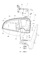
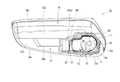
この発明の手動格納・電動格納共用ベースを使用して構成したこの発明の手動格納式ドアミラーの実施の形態1を説明する。図1はこの実施の形態による手動格納式ドアミラーの構成を分解して示す。このドアミラーは右側用で、図1は背面側から見た状態を示す。図1ではハウジング(ミラーボデー)36の背面側に装着するハウジングカバー、ハウジング36の前面側空間37a(図4)内に固定配置する鏡面調整用アクチュエータ、鏡面角度を可変に該鏡面調整用アクチュエータに固定支持されるミラー板等は図示を省略している。このドアミラーは車体外側に取り付けられるベース32と、ベース32に対し回転軸Sの周り方向に回転自在に軸受支持されるハウジング支持部材34(フレーム)と、ハウジング支持部材34に固定支持されるハウジング36を具備する。ハウジング36はハウジング支持部材34を内部空間37の凹所42に収容してハウジング支持部材配置空間37baに配置し、ビス44でハウジング支持部材34に固定支持される。このようにハウジング支持部材34とハウジング36とを相互に連結固定して一体化してミラー回転部35が構成される。ハウジング支持部材34とハウジング36とを一体化した状態では、ハウジング支持部材34のシャフト38とその外周側の環状壁40はハウジング36の下面から下方に向けて突出する。このシャフト38と環状壁40をベース32の回転支持部32bに形成されたシャフト挿通孔56と環状壁収容溝58(図8、図9)にそれぞれ差し込み、次いでベース32の下面側からシャフト38にコイルばね46を短縮(圧縮)して嵌挿装着し、さらにシャフト38の下端部にプレート48を装着することにより、ハウジング支持部材34とベース32は相互に連結される。これによりハウジング36は手動操作でハウジング支持部材34を伴って、ストッパ40c(図7)で規制される角度範囲内で回転軸Sの周り方向に回転して格納位置(後方可倒位置)と復帰位置さらには前方側に倒れた位置(前方可倒位置)に変位可能となる。
<< Embodiment 1 of Manual Retractable Door Mirror >>
A first embodiment of a manually retractable door mirror according to the present invention configured using the manual retractable / electrically retractable shared base according to the present invention will be described. FIG. 1 is an exploded view of the configuration of a manually retractable door mirror according to this embodiment. This door mirror is for the right side, and FIG. 1 shows a state seen from the back side. In FIG. 1, a housing cover mounted on the rear side of the housing (mirror body) 36, a mirror surface adjustment actuator fixedly disposed in the
図1のハウジング支持部材34、ハウジング36、ベース32についてそれぞれ説明する。ハウジング支持部材34はPA+GF(ガラス繊維入りのポリアミド)樹脂等の硬質プラスチックによる一体成型品あるいはアルミ等の金属による一体鋳造品等で構成されている。図1に示すように、ハウジング支持部材34にはベース32と相対回転する回転軸S上に配置される中空丸棒状のシャフト38と、シャフト38よりも外周側に離れた位置でシャフト38に対し径方向に間隙を隔てて同軸に配置された円形の環状壁40が形成されている。シャフト38はハウジング支持部材34に一体に形成されているので、シャフト専用部品が不要となって部品点数が削減される。これにより組み付け作業の効率化が図られる。環状壁40の板厚は下方に行くに従い僅かに薄くなるように形成されている(図6)。環状壁40は、環状壁40とシャフト38を繋ぐ円板状の連結部39(図3,図6)を越えてそのまま上方に突出して環状壁延長部41を構成している。環状壁延長部41は環状壁40の剛性を高める働きをする。図6に示すように、環状壁40と連結部39とシャフト38で囲まれた空間内には、連結部39と環状壁40との境界部分(環状壁40のすぐ内周側)に、シャフト38および環状壁40と同軸に配置されたクラッチのミラー回転部側部分54が形成されている。クラッチのミラー回転部側部分54は図4に示すように、山部54aと谷部54bの繰り返し構造を周方向に等ピッチで3回繰り返し形成して構成されている。山部54aと谷部54bの境界部分54cはそれぞれ傾斜面に形成されている(図12)。図7に示すように、環状壁40の外周面の周方向の一部の領域にはストッパ40cが径方向に突出して形成されている。ストッパ40cは、図8のベース32の環状壁収容溝58のすぐ外周側の位置で回転軸Sを中心とする周方向の一部の領域に形成されたストッパ移動溝63に収容されて、ハウジング支持部材34の回転に伴ってストッパ移動溝63を移動し、ストッパ移動溝63の両端部63a,63bに当接して係止される。ストッパ40cが端部63aで係止される位置がハウジング36の前方可倒位置であり、ストッパ40cが端部63bで係止される位置がハウジング36の格納位置(後方可倒位置)である。ストッパ40cは環状壁40の外周面に形成されているので、環状壁40が無くストッパ40cがその基部だけでハウジング支持部材34に連結されている場合に比べて、ストッパ40cを強固に支持することができ、ストッパ40cが折れるのを防止することができる。なお上記の配置とは逆に、ストッパ移動溝63を環状壁収容溝58のすぐ内周側の位置に形成し、ストッパ40cを環状壁40の内周面に突出形成することもできる。図7に示すように、ハウジング支持部材34の前面側には鏡面調整用アクチュエータの一部分をねじ止め支持するねじ穴29,31が形成されている。
The
図1のハウジング36はハウジング支持部材34よりも剛性が低いABS等のプラスチックによる一体成型品で作られている。図1に示すように、ハウジング36は内部空間37が仕切り板36aで前面側空間37aと背面側空間37bとに概ね仕切られている。前面側空間37a(図4)内には、図示しない鏡面調整用アクチュエータが仕切り板36aの前面側に配置して収容される。すなわち、鏡面調整用アクチュエータは一部分が該仕切り板36aの前面に形成されたねじ穴(図示せず)にねじ止め固定され、他の一部分がハウジング支持部材34の前面側のねじ穴29,31(図7)にねじ止め固定される。鏡面調整用アクチュエータには図示しないミラー板が装着される。背面側空間37bにはハウジング支持部材34を上方から差し込んで配置可能なハウジング支持部材配置空間37ba(電動格納式ドアミラーの電動駆動機構配置空間と共通)(図1)が形成されている。ハウジング支持部材配置空間37baの下部には上方に開口する凹所42(図1,2,3,5)が形成されている。凹所42にはハウジング支持部材34が収容される。ハウジング36の背面側にはねじ通し穴33(図1)が形成されている。ねじ通し穴33にはねじ(図示せず)が差し込まれてハウジング支持部材34の背面側に形成されたねじ穴43(図1)にねじ込まれる。これによりハウジング36とハウジング支持部材34とはハウジング36の背面側からも固定される。ハウジング36の背面側空間37bは図示しないハウジングカバーが装着されて閉じられる。ハウジング36の底面には回転軸S上に、ハウジング支持部材34のシャフト38と環状壁40を突出させる丸穴52(図2)が形成されている。丸穴52にはストッパ40c(図7),73a(図17)を通すための切欠52a(図2、図4、図13、図19)が形成されている。
The
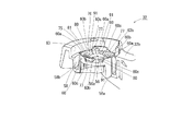
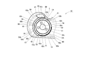
図1のベース32(手動格納・電動格納共用ベース)はPA+GF樹脂等の硬質プラスチックによる一体成型品あるいはアルミ等の金属による一体鋳造品等で構成されている。ベース32は車体に固定される車体固定部32aと、車体固定部32aの下端部から側方に突出してハウジング支持部材34を回転自在に軸受支持する回転支持部32bを有する。図8はベース32の回転支持部32bを上から見た状態を示す。図9は回転支持部32bの一部を破断して示した斜視図である。回転支持部32bには回転軸S上にシャフト挿通孔56とその外周側に環状壁収容溝58と、環状壁収容溝58のすぐ内周側にクラッチのベース側部分60が同軸に形成されている。シャフト挿通孔56はハウジング36が復帰位置にあるときにシャフト38を僅かなクリアランスで挿通する大きさに形成されている。環状壁収容溝58の内壁面58aおよび外壁面58bには、環状壁40(図6)の内壁面40aおよび外壁面40bとの当接箇所を設定する突条59,61が回転軸Sと平行な方向に延在してかつ周方向に等角度間隔に配置した状態に6本ずつ突出形成されている。環状壁収容溝58と環状壁40は、ハウジング36が復帰位置にあるときに内壁面58a(突条59の位置),40aどうしおよび外壁面58b(突条61の位置),40bどうしがクリアランスなしで当接する内径、外径に形成されている。環状壁収容溝58の溝幅は環状壁40の板厚の変化に合わせて、下方に行くに従い僅かに狭くなるように形成されている(図6)。環状壁収容溝58の深さは、ハウジング支持部材34がベース32に対し相対回転できる角度範囲内で、クラッチのミラー回転部側部分54とベース側部分60とが常に押圧当接し合える十分な深さに形成されている。クラッチのベース側部分60は環状壁収容溝58のすぐ内周側に山部60aと谷部60bの繰り返し構造を周方向に等ピッチで3回繰り返し形成して構成されている(図8、図9)。山部60aと谷部60bの境界部分60cはそれぞれ傾斜面に形成されている(図9、図12)。
The base 32 shown in FIG. 1 (manual storage / electric storage base) is composed of an integrally molded product made of hard plastic such as PA + GF resin or an integrally cast product made of metal such as aluminum. The
図1の手動格納式ドアミラーは例えば次の手順で組み立てられる。
(1)ハウジング36の凹所42にハウジング支持部材34を収容して、ハウジング支持部材34をハウジング支持部材配置空間37baに配置する。図3、図4、図5はこのときの状態を平面図、底面図、背面図でそれぞれ示す。
(2)ハウジング36の下面に形成された2個のねじ通し穴50(図4)にビス44(図1)をそれぞれ差し込んでハウジング支持部材34の下面のねじ穴にねじ込むことにより、ハウジング36とハウジング支持部材34とを相互に連結固定する。 図11はハウジング支持部材34とハウジング36の連結固定位置の断面(図4のB−B矢視位置の断面に相当)を示す。ハウジング支持部材34とハウジング36は、ハウジング36に形成されたねじ通し穴50からビス44を差し込んで、ハウジング支持部材34に形成されたねじ穴66にねじ込むことにより連結固定されている。
(3)ハウジング36の底面の丸穴52から下方に突出するシャフト38と環状壁40をベース32の回転支持部32bに形成されたシャフト挿通孔56と環状壁収容溝58にそれぞれ回転自在に差し込む(図6、図10、図11)。
(4)ベース32の下面側に突出したシャフト38にコイルばね46を嵌挿し、シャフト38の下端部にプレート48を装着して、シャフト38にコイルばね46を短縮状態に装着し、もってベース32にハウジング支持部材34を介してハウジング36を回転軸Sの周り方向に回転自在に連結して軸受支持する(図6、図10、図11)。
(5)ハウジング36の背面側のねじ通し穴33(図1)からねじ(図示せず)を差し込んで、ハウジング支持部材34のねじ穴43(図1)にねじ込んでハウジング36とハウジング支持部材34との連結を強固にする。
(6)ハウジング36の裏面側の開口(図1、図2、図3、図5に示すエッジ36cで囲まれた領域)にハウジングカバーを装着する。これによりハウジング支持部材34は、ハウジング36の下面から突出しているシャフト38および環状壁40を除く部分すなわち連結部39よりも上の部分がハウジング36の内部空間37に収容された状態となる。
(7)ハウジング36の前面側空間37aに鏡面調整用アクチュエータを装着し、該鏡面調整用アクチュエータにミラー板を装着する。
The manually retractable door mirror of FIG. 1 is assembled, for example, by the following procedure.
(1) The
(2) By inserting screws 44 (FIG. 1) into two screw-through holes 50 (FIG. 4) formed on the lower surface of the
(3) The
(4) The
(5) A screw (not shown) is inserted from the screw-through hole 33 (FIG. 1) on the back side of the
(6) A housing cover is attached to the opening on the back side of the housing 36 (region surrounded by the
(7) A mirror surface adjustment actuator is attached to the
図6は図1のドアミラーを組み立てて、ハウジング36が復帰位置にあるときに、回転軸Sを通る面で切断した状態を示す(図4、図8のA−A矢視位置の断面に相当)。シャフト38の中空部38aには鏡面調整用アクチュエータ等に駆動用電力を供給するハーネス62が挿通されている。ベース32の下部開口部は蓋64で閉じられている。ハウジング36が復帰位置にあるときはコイルばね46の付勢力はベース32とハウジング支持部材34との間に、回転軸Sに沿って相互に突き合わせる方向に付与され、クラッチのベース側部分60(図8、図9)の山部60a、谷部60bとミラー回転部側部分54(図4)の谷部54b、山部54aとが相互に噛み合った状態(図12に示す状態)となる。これによりハウジング36を装着したハウジング支持部材34はベース32上に起立した状態に保持される。このとき環状壁40の内外壁面40a,40bと環状壁収容溝58の内外壁面58a,58bの突条59,61とはいずれも当接した状態となり、ハウジング36はがたつき無く復帰位置に保持される。シャフト38の外周面38bとシャフト挿通孔56の内周面56aとの間には僅かなクリアランスがある。
6 shows a state in which the door mirror of FIG. 1 is assembled and cut along a plane passing through the rotation axis S when the
ハウジング36が復帰位置にある状態からコイルばね46の付勢力に抗してハウジング36に手で回転軸Sの周り方向に力を加えると、クラッチのミラー回転部側部分54の傾斜面54c(図12)がベース側部分60の傾斜面60cを滑り上がってクラッチの噛み合いが外れる。このとき傾斜面54cの滑り上がりによりハウジング支持部材34がその分上方に移動する。前述のように環状壁40の板厚は下方に行くに従い僅かに薄くなるように形成され、環状壁収容溝58の溝幅は環状壁40の板厚の変化に合わせて、下方に行くに従い僅かに狭くなるように形成されているので(図6)、ハウジング支持部材34が上方に移動することにより、環状壁40の内外壁面40a,40bと環状壁収容溝58の内外壁面58a,58bの突条59,61との当接が緩められ(両壁面間に隙間が生じ)、ハウジング36は回転軸Sの周り方向に回転できるようになり、格納位置(後方可倒位置)あるいは格納位置とは反対側の前方可倒位置に変位する。このハウジング36が回転するときの軸受支持は、環状壁40の内外壁面40a,40bと環状壁収容溝58の内外壁面58a,58bとの摺動、あるいはシャフト38の外周面38bとシャフト挿通孔56の内周面56aとの摺動、あるいはこれら両摺動によって行われる。
When force is applied by hand to the
ハウジング36が復帰位置にある状態でハウジング36に無用な外力が加わって(例えばハウジング36に上から荷重がかかる等)、ハウジング支持部材34に掛かる曲げモーメント(図6のシャフト挿通孔56の中心位置Pを中心とする矢印Fで示す方向のモーメント)が増大してハウジング支持部材34に傾きが生じたときは、環状壁40の内外壁面40a,40bと環状壁収容溝58の内外壁面58a,58bの突条59,61とが押圧当接し、またシャフト38に傾きが生じてシャフト38の外周面38bとシャフト挿通孔56の内周面56aとが押圧当接して、これら3面の押圧当接で該外力を分担して支持する。したがってハウジング支持部材34は全体として高い剛性が得られ、外力に対して高い支持力が得られる。したがってハウジング支持部材34を金属でなくPA+GF樹脂等の硬質プラスチックによる一体成型品で作ってもシャフト38や環状壁40が折れたり曲がったり破損するのが防止される。ハウジング支持部材34およびベース32をいずれもPA+GF樹脂等の硬質プラスチックによる一体成型品で作ればドアミラーを安価に製造することができる。特にこの実施の形態によれば、ハウジング36が復帰位置にあるときに、環状壁40の内外壁面40a,40bと環状壁収容溝58の内外壁面58a,58bの突条59,61どうしがクリアランスなしで当接し、シャフト38の外周面38bとシャフト挿通孔56の内周面56aとは僅かなクリアランスで対面しているので、ハウジング36に外力が加わったときに、環状壁40の内外壁面40a,40bと環状壁収容溝58の内外壁面58a,58bの突条59,61どうしの押圧当接で該外力の多くの部分を支持し、シャフト38の外周面38bとシャフト挿通孔56の内周面56aとの押圧当接で該外力の残りの部分を支持するので、シャフト38に掛かる力を軽減してシャフト38が折れたり曲がったりするのをより確実に防止することができる。
A bending moment applied to the housing support member 34 (for example, the center position of the
また上記実施の形態によれば、環状壁40は環状壁収容溝58に収容されて隠されるので、従来の車両用ドアミラーと同等の外観を保つことができる。またクラッチ54,60は環状壁40および環状壁収容溝58よりも内周側に配置されているので、環状壁40および環状壁収容溝58よりも外周側にクラッチを配置するための径方向の専用幅(クラッチを形成するためにハウジング支持部材34およびベース32に設ける回転軸Sに関する径方向の幅)が不要である。またシャフト38の中空部38aにハーネス62を通すので、ハーネス62の取り回しが容易である。またコイルばね46は環状壁収容溝58よりも内周側(回転支持部32bの下面側に構成された凹所57(図6参照))に配置されているので、コイルばね46の直径を小さくすることができる。
Moreover, according to the said embodiment, since the
《手動格納式ドアミラーの実施の形態2》
この発明の手動格納・電動格納共用ベースを使用して構成したこの発明の手動格納式ドアミラーの実施の形態2を図13〜図15に示す。これはクラッチのミラー回転部側部分54を環状壁40の頂部に形成し、クラッチのベース側部分60を環状壁収容溝58の底部に形成したものである。他の構成は実施の形態1と同じである。図13はハウジング36の凹所42(図2)にハウジング支持部材34を収容して(図3)ハウジング36の底面側から見た図(実施の形態1の図4に相当)、図14はベース32の回転支持部32bの平面図(実施の形態1の図8に相当)、図15はハウジング36が復帰位置にあるときに、回転軸Sを通る面で切断した断面図(実施の形態1の図6に相当)である。実施の形態1と共通する部分には同一の符号を用いる。これによれば、クラッチを配置するための径方向の専用幅が不要となるので、ベース32とハウジング支持部材34が相対回転する部分の径を小さくすることができる。この実施の形態のドアミラーは実施の形態1のドアミラーと同様に動作する。
<< Second Embodiment of Manual Retractable Door Mirror >>
A second embodiment of the manually retractable door mirror of the present invention configured using the manual retractable / electrically retractable shared base of the present invention is shown in FIGS. In this configuration, the mirror rotating
なお前記手動格納式ドアミラーの実施の形態1,2ではハウジング36とハウジング支持部材34を別体で構成して組み付けたが、両者を一体成型品または一体鋳造品として構成することもできる。また同実施の形態1,2ではコイルばね46をシャフト38に係止するためにプレート48を用いたが、コイルばね46のプレート側の端部をシャフト38に直接係止する構造にすればプレート48を省くこともできる。また同実施の形態1,2ではばねとしてコイルばね46を使用した場合について説明したが、皿ばねや板ばねを使用することもできる。
In Embodiments 1 and 2 of the manual retractable door mirror, the
《電動格納式ドアミラーの実施の形態》
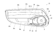
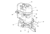
前記手動格納式ドアミラーの実施の形態1で説明した手動格納・電動格納共用ベース32を使用して構成したこの発明の電動格納式ドアミラーの実施の形態を図16〜図23に示す。前記手動格納式ドアミラーの実施の形態1と共通する部分には同一の符号を用いる。図16はこの実施の形態による電動格納式ドアミラーの構成を分解して示す。このドアミラーは右側用で、図16は背面側から見た状態を示す。図16ではハウジング36の背面側に装着するハウジングカバー、鏡面調整用アクチュエータ、ミラー板等は図示を省略している。このドアミラーは車体外側に取り付けられるベース32と、電動駆動機構70と、取付部品72と、ハウジング36を具備する。取付部品72は電動駆動機構70とハウジング36との間に介在して電動駆動機構70をハウジング36に固定連結する働きをする。取付部品72はPA+GF樹脂等の硬質プラスチックによる一体成型品あるいはアルミ等の金属による一体鋳造品等で構成される。取付部品72は電動駆動機構70を上部の開口部72bから嵌め込んで収容する内部空間72aを有する。取付部品72の下面にはシャフト74(図22,図23)の下面74aaを下方に露出させる開口部72cが形成されている。取付部品72は下方に向けて突出する環状壁73を有する。環状壁73はベース32の環状壁収容溝58に非接触で収容される(図22、図23)。図17に示すように、環状壁73の外周面の周方向の一部の領域にはストッパ73aが径方向に突出して形成されている。ストッパ73aは、手動格納式ドアミラーの場合と同様に、図8のベース32の環状壁収容溝58のすぐ外周側位置で回転軸Sを中心とする周方向の一部の領域に形成されたストッパ移動溝63に収容されて、取付部品72の回転に伴ってストッパ移動溝63を移動し、ストッパ移動溝63の両端部63a,63bに当接して係止される。ストッパ73aが端部63aで係止される位置がハウジング36の前方可倒位置であり、ストッパ73aが端部63bで係止される位置がハウジング36の格納位置(後方可倒位置)である。ストッパ73aは環状壁73の外周面に形成されているので、環状壁73が無くストッパ73aがその基部だけで取付部品72に連結されている場合に比べて、ストッパ73aを強固に支持してストッパ73aが折れるのを防止することができる。なお上記の配置とは逆に、ストッパ移動溝63を環状壁収容溝58のすぐ内周側の位置に形成し、ストッパ73aを環状壁73の内周面に突出形成することもできる。図17に示すように、取付部品72の前面側には鏡面調整用アクチュエータの一部分をねじ止め支持するねじ穴67,69(図7のハウジング支持部材34のねじ穴29,31に相当)が形成されている。図16において、電動駆動機構70は取付部品72の内部空間72aに収容保持されて、取付部品72ごとハウジング36の凹所42に収容保持されて電動駆動機構配置空間37ba(手動格納式ドアミラーのハウジング支持部材配置空間と共通)に配置され、ビス44で取付部品72ごとハウジング36に固定支持される。このように取付部品72に収容された電動駆動機構70とハウジング36とを一体化してミラー回転部35が構成される。ベース32、ハウジング36、ハウジングカバーは前記手動格納式ドアミラーの実施の形態1で説明したものと同一のものである。なお電動駆動機構70がハウジング36の凹所42に直接収容保持されるように電動駆動機構70の外形および凹所42の内形を形成すれば、取付部品72を不要にすることができる。
<< Embodiment of electric retractable door mirror >>
16 to 23 show an embodiment of the electric retractable door mirror of the present invention configured using the manual retractable / electrically retractable shared
電動駆動機構70は従来の電動格納式ドアミラーの電動駆動機構と同様の機構を有するものであり、ケース71内に中空丸棒状の金属製シャフト74(図22,図23)、モータ、ギヤ、クラッチ機構、コイルばね、電子回路基板等を収容配置して構成されている。シャフト74は回転軸Sと同軸に配置される。シャフト74の基部74aの下面74aaはハウジング36の下面に露出する。シャフト74の基部74aの下部には図19に示すように、回転軸Sを取り囲む3箇所に脚90が突出形成されている。各脚90の下面にはねじ穴88が形成されている。またシャフト74の基部74aの下部には図19に示すように、1本の位置決め用ピン79が突出形成されている。シャフト74の中心には上下に貫通する中空部74bが形成されている。中空部74bの下端部は基部74aの下面74aaの中央部に開口している。中空部74bの上端部は電動駆動機構70のケース71の上部に形成された中空部92(図22、図23)に連通し、電動駆動機構70の上方に開口している。
The
ベース32の上面中央部にはシャフト立設固定面76(図8、図9)が構成されている。シャフト立設固定面76には、図8、図9に示すように、壁部77とボス75が突出形成されている。シャフト立設固定面76のうち壁部77およびボス75が形成されていない領域は脚90を支持する脚支持面91を構成する。脚支持面91にはねじ通し穴80が形成されている。ボス75にはピン収容穴81が形成されている。シャフト74は脚90を脚支持面91に着地させてシャフト立設固定面76に支持される。この状態では壁部77およびボス75は脚90どうしの隙間に嵌り込み、ピン収容穴81にはピン79が収容される。このようなシャフト立設固定面76の凹凸とシャフト74の下面74aaの凹凸との係合(嵌め合い)により、シャフト74はその中心軸を回転軸Sに一致させてベース32上に位置決めされる。シャフト74がベース32上に位置決めされた状態で、ベース32の下面側から3本のビス78(図16)をねじ通し穴80に通して脚90の下面に形成されたねじ穴88にねじ込むことによりシャフト74はベース32上に立設固定される(図23)。シャフト74がベース32上に立設固定された状態では、ベース32の中心穴56(手動格納式手動格納式ドアミラーの場合のシャフト挿通孔)、シャフト74の中空部74b、ケース71の中空部92は相互に連通してハーネス通し穴を構成する。
A shaft standing fixing surface 76 (FIGS. 8 and 9) is formed at the center of the upper surface of the
図16の電動格納式ドアミラーは例えば次の手順で組み立てられる。
(1)取付部品72の上部開口部72bからその内部空間72aに電動駆動機構70を嵌め込んで収容する。これにより電動駆動機構70の約下半分が内部空間72aに嵌り込んだ状態で、電動駆動機構70に取付部品72が装着される。このとき電動駆動機構70のシャフト74の基部74aの下面74aaは取付部品72の下部開口部72cから下方に露出した状態となる。
(2)取付部品72が装着された電動駆動機構70をハウジング36の凹所42に上方から収容する。図18、図19、図20はこのときの状態を平面図、底面図、背面図でそれぞれ示す。
(3)ハウジング36の下面に形成された2個のねじ通し穴50(図19)にビス44(図16)をそれぞれ差し込んで電動駆動機構70の下面のねじ穴にねじ込むことにより、ハウジング36と電動駆動機構70とを相互に連結固定する。 図22は電動駆動機構70とハウジング36の連結固定位置の断面(図19のD−D矢視位置の断面に相当)を示す。図22に示すように、電動駆動機構70とハウジング36は、ハウジング36に形成されたねじ通し穴50からビス44を差し込んで、取付部品72に形成されたねじ通し穴82を介して、電動駆動機構70に形成されたねじ穴84にねじ込むことにより連結固定される。
(4)ハウジング36の下面に露出しているシャフト74の基部74aをベース32のシャフト立設固定面76に、シャフト74の中心軸を回転軸Sに合わせて載置する。図21は取付部品72およびハウジング36を外してベース32の回転支持部32bに電動駆動機構70を載置した状態を示す。脚90と壁部77との係合およびピン79(図19)とピン収容穴81(図8、図9)との係合によりシャフト74の基部74aはベース32のシャフト立設固定面76に位置決めされる。
(5)ベース32の回転支持部32bの裏面側から、ねじ通し穴80(図8)にビス78(図16)を差し込み、シャフト74の下面74aaに形成されたねじ穴88(図19)にねじ込むことにより、シャフト74は回転支持部32bに立設固定される。これによりミラー回転部35は回転支持部32bに対し回転軸Sの周り方向に回転自在に連結される。図22、図23はこのときの状態を断面図で示す。
(6)ハウジング36の背面側のねじ通し穴33(図1)からねじ(図示せず)を差し込んで、取付部品72のねじ通し穴87(図16)に通して、電動駆動機構70のねじ穴89(図16)にねじ込んでハウジング36と取付部品72と電動駆動機構70との連結を強固にする。
(7)ハウジング36の裏面側の開口(図16、図18、図20に示すエッジ36cで囲まれた領域)にハウジングカバーを装着する。これにより電動駆動機構70は、ハウジング36の下面から突出しているシャフト74の基部74aを除く部分がハウジング36の内部空間37に収容された状態となる。
(8)ハウジング36の前面側空間37aに鏡面調整用アクチュエータを装着し、該鏡面調整用アクチュエータにミラー板を装着する。
The electric retractable door mirror of FIG. 16 is assembled by the following procedure, for example.
(1) The
(2) The
(3) Screws 44 (FIG. 16) are respectively inserted into two screw-through holes 50 (FIG. 19) formed on the lower surface of the
(4) The
(5) A screw 78 (FIG. 16) is inserted into the screw-through hole 80 (FIG. 8) from the back side of the
(6) A screw (not shown) is inserted from the screw-through hole 33 (FIG. 1) on the back side of the
(7) Attach the housing cover to the opening on the back side of the housing 36 (region surrounded by the
(8) A mirror surface adjustment actuator is attached to the
図23は図16のドアミラーを組み立てて、ハウジング36が復帰位置にあるときに、図8、図19のC−C矢視位置に相当する位置で切断した断面を示す。相互に連通するシャフト74の中空部74bおよびケース71の中空部92には電動駆動機構70および鏡面調整用アクチュエータ等に駆動用電力を供給するハーネス62が挿通されている。ベース32の下部開口部は蓋64で閉じられている。電動駆動機構70内のモータが駆動されると、電動駆動機構70はベース32の回転支持部32bに立設固定されたシャフト74を中心にケース71が回転し、ケース71に連結されているハウジング36はこれに従動して、ストッパ73a(図17))で規制される角度範囲内で回転軸Sの周り方向に回転し、復帰位置から格納位置に、または格納位置から復帰位置に変位する。またハウジング36が復帰位置にあるときにハウジング36に車両前方方向への外力が作用すると、電動駆動機構70内でコイルばねの付勢力に抗してクラッチの噛み合いが外れてハウジング36は前方側に倒れた位置(前方可倒位置)に変位して、該外力を逃がす。
FIG. 23 shows a cross section obtained by assembling the door mirror of FIG. 16 and cutting at a position corresponding to the CC arrow position of FIGS. 8 and 19 when the
以上は手動格納式ドアミラーの実施の形態1で説明した手動格納・電動格納共用ベースを使用してこの発明の電動格納式ドアミラーを構成した例を説明したが、手動格納式ドアミラーの実施の形態2で説明した手動格納・電動格納共用ベースを使用してこの発明の電動格納式ドアミラーを構成することもできる。 The example in which the electric retractable door mirror of the present invention is configured using the manual retractable / electrically retractable shared base described in the first embodiment of the manual retractable door mirror has been described. The electric retractable door mirror of the present invention can also be configured using the manual retractable / electrically retractable shared base described in the above.
《手動格納式または電動格納式ドアミラーの選択的製造方法の実施の形態》
手動格納式ドアミラーの実施の形態1で説明した手動格納・電動格納共用ベース32を複数個用意して、そのうちのあるものを手動格納式ドアミラーの実施の形態1で説明した手動格納式ドアミラーを製造するのに使用し、他のあるものを電動格納式ドアミラーの実施の形態で説明した電動格納式ドアミラーを製造するのに使用することができる。同様に、手動格納式ドアミラーの実施の形態2で説明した手動格納・電動格納共用ベース32を複数個用意して、そのうちのあるものを手動格納式ドアミラーの実施の形態2で説明した手動格納式ドアミラーを製造するのに使用し、他のあるものを電動格納式ドアミラーの実施の形態で説明したのと同様の電動格納式ドアミラーを製造するのに使用することができる。
<< Embodiment of Selective Manufacturing Method of Manual Retractable or Electric Retractable Door Mirror >>
Prepare a plurality of manually retractable / electrically retractable shared
32…手動格納・電動格納共用ベース、32a…車体固定部、32b…回転支持部、35…ミラー回転部、36…ハウジング、38…第2のシャフト、40,73…環状壁、40c,73a…ストッパ、46…コイルばね(ばね)、54…クラッチのミラー回転部側部分、56…シャフト挿通孔,中心穴、57…凹所、58…環状壁収容溝、60…クラッチのベース側部分、62…ハーネス、63…ストッパ移動溝、63a,63b…ストッパ移動溝の端部、74…第1のシャフト、76…シャフト立設固定面、70…電動駆動機構、S…回転軸 32 ... Manual storage / electric storage common base, 32a ... body fixing portion, 32b ... rotation support portion, 35 ... mirror rotation portion, 36 ... housing, 38 ... second shaft, 40,73 ... annular wall, 40c, 73a ... Stopper, 46 ... Coil spring (spring), 54 ... Mirror rotating part side portion of clutch, 56 ... Shaft insertion hole, center hole, 57 ... Recess, 58 ... Ring wall receiving groove, 60 ... Base side portion of clutch, 62 ... Harness, 63 ... Stopper moving groove, 63a, 63b ... End of stopper moving groove, 74 ... First shaft, 76 ... Shaft standing fixed surface, 70 ... Electric drive mechanism, S ... Rotating shaft
Claims (10)
前記回転支持部の上面側に、
電動格納式ドアミラーの回転軸を構成する第1のシャフトを立設固定するシャフト立設固定面と、
前記シャフト立設固定面の中央部に形成され、手動格納式ドアミラーに使用する場合は前記ミラー回転部からその回転軸上を下方に向けて突出形成された第2のシャフトを回転自在に挿通し、電動格納式ドアミラーに使用する場合は前記シャフト立設固定面に立設固定された第1のシャフト内を通って下方に引き出されるハーネスを挿通する中心穴と、
前記中心穴よりも外周側の位置で該中心穴と同心の円形に形成され、手動格納式ドアミラーに使用する場合に、前記ミラー回転部の前記第2のシャフトよりも外周側の位置で該第2のシャフトと同軸に下方に向けて配置されたミラー回転部側の環状壁を回転自在に収容する環状壁収容溝と
を具備してなる車両用ドアミラーの手動格納・電動格納共用ベース。 A base shared by a manually retractable door mirror and an electrically retractable door mirror, and is provided with a vehicle body fixing portion attached to the outside of the vehicle body, and connected to the vehicle body fixing portion. And a rotation support part that is displaced to the return position,
On the upper surface side of the rotation support part,
A shaft erecting fixing surface for erecting and fixing a first shaft constituting the rotating shaft of the electric retractable door mirror;
A second shaft formed at the center of the shaft standing fixing surface and projecting downward from the mirror rotating portion toward the rotating shaft when used for a manually retractable door mirror is rotatably inserted. In the case of using the electric retractable door mirror, a center hole through which a harness is drawn downward through the first shaft that is erected and fixed to the shaft erection fixing surface,
It is formed in a circular shape concentric with the center hole at a position on the outer peripheral side of the center hole, and when used for a manually retractable door mirror, the first part of the mirror rotating portion is positioned on the outer peripheral side of the second shaft. A vehicle door mirror manual retractable / electrically retractable shared base comprising: an annular wall housing groove that rotatably accommodates an annular wall on the mirror rotating portion side that is disposed coaxially with the shaft of 2 downward.
前記環状壁収容溝よりも内周側に相当する位置に、手動格納式ドアミラーに使用する場合にばねを配置する凹所を具備してなる請求項1記載の車両用ドアミラーの手動格納・電動格納共用ベース。 The manual storage and electric storage of a vehicle door mirror according to claim 1, further comprising a recess in which a spring is disposed when used for a manually retractable door mirror at a position corresponding to an inner peripheral side of the annular wall housing groove. Shared base.
前記環状壁収容溝よりも内周側に相当する位置に、手動格納式ドアミラーに使用する場合にばねを配置する凹所を具備してなる請求項3記載の車両用ドアミラーの手動格納・電動格納共用ベース。 The manual storage / electric storage of a vehicle door mirror according to claim 3, further comprising a recess in which a spring is disposed when used for a manually retractable door mirror at a position corresponding to an inner peripheral side of the annular wall housing groove. Shared base.
前記第2のシャフトおよび前記環状壁を具え、該第2のシャフトを前記ベースの前記シャフト立設固定面の中心穴に回転自在に挿通し、かつ該環状壁を前記ベース側の環状壁収容溝に回転自在に収容して該ベースに回転自在に支持されるミラー回転部と、
前記シャフト立設固定面の中心穴を通って前記ベースの下面側に突出する前記第2のシャフトに圧縮状態で嵌挿装着され、前記ベースと前記ミラー回転部との間に前記回転軸に沿って相互に突き合わす方向に付勢力を付与するばねと
を具備してなる手動格納式ドアミラー。 The manual storage / electric storage common base according to claim 1 or 2 ,
The second shaft and the annular wall are provided, the second shaft is rotatably inserted into a center hole of the shaft standing fixing surface of the base, and the annular wall is inserted into the base-side annular wall receiving groove. A mirror rotating part that is rotatably accommodated in the base and is rotatably supported by the base;
The second shaft protruding from the lower surface side of the base through the center hole of the shaft standing fixing surface is fitted and mounted in a compressed state, and is along the rotation axis between the base and the mirror rotating portion. And a spring for applying an urging force in a direction in which they face each other.
前記第2のシャフトおよび前記環状壁および前記クラッチのミラー回転部側部分を具え、該第2のシャフトを前記ベースの前記シャフト立設固定面の中心穴に回転自在に挿通し、かつ該環状壁を前記ベース側の環状壁収容溝に回転自在に収容して該ベースに回転自在に支持されるミラー回転部と、
前記シャフト立設固定面の中心穴を通って前記ベースの下面側に突出する前記第2のシャフトに圧縮状態で嵌挿装着され、前記ベースと前記ミラー回転部との間に前記回転軸に沿って相互に突き合わす方向に付勢力を付与して、前記クラッチのミラー回転部側部分とベース側部分どうしを圧接させるばねと
を具備してなる手動格納式ドアミラー。 The manual storage / electric storage common base according to claim 3 or 4 ,
The second shaft, the annular wall, and a mirror rotating portion side portion of the clutch, the second shaft being rotatably inserted into a center hole of the shaft standing fixing surface of the base, and the annular wall A mirror rotating part rotatably received in the base-side annular wall receiving groove and rotatably supported by the base;
The second shaft protruding from the lower surface side of the base through the center hole of the shaft standing fixing surface is fitted and mounted in a compressed state, and is along the rotation axis between the base and the mirror rotating portion. And a spring that presses the mirror rotating portion side portion and the base side portion of the clutch together by applying an urging force in a direction in which they face each other.
前記ミラー回転部が前記環状壁の外周面または内周面に径方向に突出して形成されたストッパを有し、
該ストッパが前記ミラー回転部の回転に伴い前記ストッパ移動溝を移動して、該ストッパ移動溝の端部に当接して係止される請求項5または6記載の手動格納式ドアミラー。 The base has a stopper moving groove adjacent to the outer peripheral side or inner peripheral side of the annular wall housing groove;
The mirror rotating part has a stopper formed to project radially on the outer peripheral surface or inner peripheral surface of the annular wall;
The manually retractable door mirror according to claim 5 or 6 , wherein the stopper moves in the stopper moving groove as the mirror rotating portion rotates, and is brought into contact with and locked to an end of the stopper moving groove.
前記シャフト立設固定面に立設固定される前記第1のシャフトと、
該第1のシャフトの軸回り方向に回転自在に支持され、内蔵する電動駆動機構による回転力を該第1のシャフトに伝達して該軸回り方向に回転駆動されるミラー回転部と
を具備してなる電動格納式ドアミラー。 A manual storage / electric storage common base according to any one of claims 1 to 4 ,
The first shaft standingly fixed to the shaft standing fixing surface;
A mirror rotating unit that is rotatably supported in the direction around the axis of the first shaft and that transmits the rotational force of the built-in electric drive mechanism to the first shaft and is driven to rotate in the direction around the axis. Electric retractable door mirror.
前記ミラー回転部が環状壁と該環状壁の外周面または内周面に径方向に突出して形成されたストッパを有し、
該ストッパが前記ミラー回転部の回転に伴い前記ストッパ移動溝を移動して、該ストッパ移動溝の端部に当接して係止される請求項8記載の電動格納式ドアミラー。 The base has a stopper moving groove adjacent to the outer peripheral side or inner peripheral side of the annular wall housing groove;
The mirror rotating portion has an annular wall and a stopper formed to project radially on the outer peripheral surface or inner peripheral surface of the annular wall;
And the stopper moves the stopper moving groove with the rotation of the mirror rotation unit, the stopper moving groove kinematic storage type door mirror collector of claim 8, wherein the end portion abut locked in.
Priority Applications (4)
| Application Number | Priority Date | Filing Date | Title |
|---|---|---|---|
| JP2009281435A JP5324410B2 (en) | 2009-12-11 | 2009-12-11 | Manual storage / electrically retractable shared base for vehicle door mirrors, manually retractable vehicle door mirrors, electric retractable vehicle door mirrors, and selective manufacturing methods for manually retractable or electrically retractable door mirrors |
| US12/961,911 US8894223B2 (en) | 2009-12-11 | 2010-12-07 | Common base for manually retractable and electrically retractable vehicle door mirrors, manually retractable vehicle door mirror, electrically retractable vehicle door mirror, and method for selectively manufacturing manually retractable/electrically retractable vehicle door mirror |
| CN201010591870.2A CN102092343B (en) | 2009-12-11 | 2010-12-10 | Common base, manually retractable/electrically retractable vehicle door mirror and method for manufacturing the same |
| DE102010054038.2A DE102010054038B4 (en) | 2009-12-11 | 2010-12-10 | Common basis for manually retractable and electrically retractable vehicle door mirrors, manually retractable vehicle door mirrors, electrically retractable vehicle door mirrors, and methods for selectively manufacturing a manually retractable / electrically retractable vehicle door mirror |
Applications Claiming Priority (1)
| Application Number | Priority Date | Filing Date | Title |
|---|---|---|---|
| JP2009281435A JP5324410B2 (en) | 2009-12-11 | 2009-12-11 | Manual storage / electrically retractable shared base for vehicle door mirrors, manually retractable vehicle door mirrors, electric retractable vehicle door mirrors, and selective manufacturing methods for manually retractable or electrically retractable door mirrors |
Publications (3)
| Publication Number | Publication Date |
|---|---|
| JP2011121493A JP2011121493A (en) | 2011-06-23 |
| JP2011121493A5 JP2011121493A5 (en) | 2013-06-20 |
| JP5324410B2 true JP5324410B2 (en) | 2013-10-23 |
Family
ID=44125672
Family Applications (1)
| Application Number | Title | Priority Date | Filing Date |
|---|---|---|---|
| JP2009281435A Active JP5324410B2 (en) | 2009-12-11 | 2009-12-11 | Manual storage / electrically retractable shared base for vehicle door mirrors, manually retractable vehicle door mirrors, electric retractable vehicle door mirrors, and selective manufacturing methods for manually retractable or electrically retractable door mirrors |
Country Status (4)
| Country | Link |
|---|---|
| US (1) | US8894223B2 (en) |
| JP (1) | JP5324410B2 (en) |
| CN (1) | CN102092343B (en) |
| DE (1) | DE102010054038B4 (en) |
Families Citing this family (11)
| Publication number | Priority date | Publication date | Assignee | Title |
|---|---|---|---|---|
| JP2014008897A (en) * | 2012-06-29 | 2014-01-20 | Murakami Corp | Door mirror |
| DE102012106882B4 (en) | 2012-07-27 | 2021-08-19 | Ford-Werke Gmbh | Motor vehicle exterior mirror holder and method for its production |
| DE102013201434B3 (en) * | 2013-01-29 | 2014-05-28 | Mekra Lang Gmbh & Co. Kg | Electric rotary adjustment unit and indirect vision system for vehicles with such an adjustment |
| US10953788B2 (en) | 2016-05-21 | 2021-03-23 | JST Performance, LLC | Method and apparatus for vehicular light fixtures |
| JP6495201B2 (en) * | 2016-06-10 | 2019-04-03 | 株式会社東海理化電機製作所 | Mirror device for vehicle |
| DE102016224649B3 (en) * | 2016-12-09 | 2018-04-19 | Magna Mirrors Holding Gmbh | Exterior mirror assembly for motor vehicles, adapter for an exterior mirror assembly, and method for mounting an exterior mirror assembly |
| CN111032434B (en) * | 2017-08-17 | 2023-09-01 | 麦格纳镜片美国有限公司 | Electric folding actuator for external mirror |
| JP1625045S (en) * | 2018-07-27 | 2019-02-18 | ||
| JP1624950S (en) * | 2018-07-27 | 2019-02-18 | ||
| DE102019219148B4 (en) | 2018-12-18 | 2021-07-08 | Magna Mirrors Holding Gmbh | Vehicle exterior mirror with fold-down function |
| JP6847999B2 (en) * | 2019-04-23 | 2021-03-24 | 株式会社ホンダロック | Vehicle door mirrors |
Family Cites Families (27)
| Publication number | Priority date | Publication date | Assignee | Title |
|---|---|---|---|---|
| JPS613756U (en) * | 1984-06-15 | 1986-01-10 | 市光工業株式会社 | Foldable outside mirror |
| JPS6112452A (en) * | 1984-06-28 | 1986-01-20 | Murakami Kaimeidou:Kk | Motor-driven inclining type door mirror |
| JPS61191447A (en) * | 1985-02-19 | 1986-08-26 | Murakami Kaimeidou:Kk | Electrically-operated retractable door mirror |
| JPS62189255U (en) * | 1986-05-26 | 1987-12-02 | ||
| US4789232A (en) * | 1987-08-14 | 1988-12-06 | Dominion Automotive Industries Inc. | Break-away pivot system for rearview mirrors |
| JPH0249753U (en) * | 1988-09-30 | 1990-04-06 | ||
| NL8902300A (en) * | 1989-09-14 | 1991-04-02 | Iku Holding Montfoort Bv | FLIP-UP MECHANISM FOR A REAR VIEW MIRROR FOR A VEHICLE. |
| DE69410370T2 (en) * | 1993-09-03 | 1998-09-17 | Ichikoh Industries Ltd | Rear-view mirror system for motor vehicles |
| JP3173291B2 (en) * | 1994-07-22 | 2001-06-04 | 市光工業株式会社 | Rearview mirror device for vehicles |
| JP3022159B2 (en) * | 1994-04-19 | 2000-03-15 | 株式会社村上開明堂 | Door mirror drive control section seal structure |
| JPH0840146A (en) * | 1994-08-03 | 1996-02-13 | Murakami Kaimeidou:Kk | Control device for electrically storing type door mirror |
| KR100198321B1 (en) * | 1995-09-22 | 1999-06-15 | 모치마루 마모루 | Positioning device for an automobile's rear mirror |
| JP3204610B2 (en) * | 1995-12-22 | 2001-09-04 | 敦 倉本 | Small blind spot door mirror |
| EP0881124B1 (en) * | 1997-05-29 | 2004-03-31 | Schefenacker Vision Systems Australia Pty Ltd | A mirror operating mechanism |
| JP3795194B2 (en) * | 1997-08-20 | 2006-07-12 | 株式会社東海理化電機製作所 | Door mirror electric storage device |
| JP3881153B2 (en) * | 2000-04-25 | 2007-02-14 | 株式会社東海理化電機製作所 | Vehicle door mirror device |
| EP1637398B1 (en) * | 2001-03-19 | 2006-11-22 | Kabushiki Kaisha Tokai-Rika-Denki-Seisakusho | Mirror device for vehicle |
| JP4012460B2 (en) * | 2002-11-28 | 2007-11-21 | 株式会社東海理化電機製作所 | Outer mirror device for vehicle |
| CN1218850C (en) * | 2002-12-16 | 2005-09-14 | 王振惠 | Electric or manual mechanism for folding rearview mirror |
| TWI232187B (en) * | 2003-06-28 | 2005-05-11 | Chaw Khong Co Ltd | Electrical operable pivoting back-mirror device |
| WO2007085960A2 (en) * | 2006-01-24 | 2007-08-02 | Fico Mirrors, Sa | Vehicle exterior rear-view mirror |
| JP2008087707A (en) * | 2006-10-04 | 2008-04-17 | Ichikoh Ind Ltd | Outside mirror device for vehicle |
| JP2008296719A (en) * | 2007-05-31 | 2008-12-11 | Ichikoh Ind Ltd | Vehicular outside mirror device |
| JP2008296336A (en) * | 2007-05-31 | 2008-12-11 | Toshiba Corp | Hollow sealing structure and manufacturing method for hollow sealing structure |
| WO2009035931A1 (en) * | 2007-09-15 | 2009-03-19 | Heinrich Wilheim A | Universal folding bracket assembly for either manual fold or power fold rearview mirrors |
| JP5501746B2 (en) * | 2009-12-11 | 2014-05-28 | 株式会社村上開明堂 | Door mirror and its assembly method |
| JP5416568B2 (en) * | 2009-12-11 | 2014-02-12 | 株式会社村上開明堂 | Manually retractable vehicle door mirror |
-
2009
- 2009-12-11 JP JP2009281435A patent/JP5324410B2/en active Active
-
2010
- 2010-12-07 US US12/961,911 patent/US8894223B2/en active Active
- 2010-12-10 CN CN201010591870.2A patent/CN102092343B/en active Active
- 2010-12-10 DE DE102010054038.2A patent/DE102010054038B4/en active Active
Also Published As
| Publication number | Publication date |
|---|---|
| CN102092343B (en) | 2014-10-22 |
| JP2011121493A (en) | 2011-06-23 |
| DE102010054038A1 (en) | 2011-06-22 |
| US20110141591A1 (en) | 2011-06-16 |
| US8894223B2 (en) | 2014-11-25 |
| DE102010054038B4 (en) | 2021-02-25 |
| CN102092343A (en) | 2011-06-15 |
Similar Documents
| Publication | Publication Date | Title |
|---|---|---|
| JP5324410B2 (en) | Manual storage / electrically retractable shared base for vehicle door mirrors, manually retractable vehicle door mirrors, electric retractable vehicle door mirrors, and selective manufacturing methods for manually retractable or electrically retractable door mirrors | |
| JP5501746B2 (en) | Door mirror and its assembly method | |
| JP4676301B2 (en) | Mirror device for vehicle | |
| US8123369B2 (en) | Shaft structure of retractable outer mirror | |
| US20040254041A1 (en) | Step down gear train, more specifically for an adjusting device of a motor vehicle seat | |
| JPH07238727A (en) | Actuator unit for vehicular door lock device | |
| JP5416568B2 (en) | Manually retractable vehicle door mirror | |
| WO2016158500A1 (en) | Electric retractable viewing device for vehicle | |
| WO2019151253A1 (en) | Sensor installation structure for rotatable windshield-mounted vehicle inner mirror | |
| JP2008247148A (en) | Driving device for vehicular power seat device | |
| JP2003267139A (en) | Rear view mirror | |
| JP4292460B2 (en) | Movement mechanism | |
| EP2095996B1 (en) | Rotatable vehicular lamp assembly having a plate spring | |
| JP4491395B2 (en) | Mirror device for vehicle | |
| JP7253350B2 (en) | gear device | |
| JP2002106543A (en) | Angle adjustment device | |
| JP2006342909A (en) | Rotor connecting structure and electric operated door mirror device | |
| CN218234732U (en) | Locking subassembly and vehicle of vehicle toolbox | |
| JP6605421B2 (en) | Vehicle door mirror device | |
| JPH0949361A (en) | Hinge member for opening/closing door | |
| US20040001417A1 (en) | Ejection structure | |
| JP2011121494A (en) | Structure for mounting coil spring and shaft of manually retractable vehicular door mirror | |
| JP3742639B2 (en) | Door frame material mounting device | |
| JP4526083B2 (en) | Portable terminal and hinge device | |
| JPH11230399A (en) | Actuator and manufacture for it |
Legal Events
| Date | Code | Title | Description |
|---|---|---|---|
| A621 | Written request for application examination |
Free format text: JAPANESE INTERMEDIATE CODE: A621 Effective date: 20120319 |
|
| A521 | Request for written amendment filed |
Free format text: JAPANESE INTERMEDIATE CODE: A523 Effective date: 20130507 |
|
| A977 | Report on retrieval |
Free format text: JAPANESE INTERMEDIATE CODE: A971007 Effective date: 20130621 |
|
| TRDD | Decision of grant or rejection written | ||
| A01 | Written decision to grant a patent or to grant a registration (utility model) |
Free format text: JAPANESE INTERMEDIATE CODE: A01 Effective date: 20130702 |
|
| A61 | First payment of annual fees (during grant procedure) |
Free format text: JAPANESE INTERMEDIATE CODE: A61 Effective date: 20130718 |
|
| R150 | Certificate of patent or registration of utility model |
Ref document number: 5324410 Country of ref document: JP Free format text: JAPANESE INTERMEDIATE CODE: R150 |
|
| R250 | Receipt of annual fees |
Free format text: JAPANESE INTERMEDIATE CODE: R250 |
|
| R250 | Receipt of annual fees |
Free format text: JAPANESE INTERMEDIATE CODE: R250 |
|
| R250 | Receipt of annual fees |
Free format text: JAPANESE INTERMEDIATE CODE: R250 |
|
| R250 | Receipt of annual fees |
Free format text: JAPANESE INTERMEDIATE CODE: R250 |
|
| R250 | Receipt of annual fees |
Free format text: JAPANESE INTERMEDIATE CODE: R250 |
|
| R250 | Receipt of annual fees |
Free format text: JAPANESE INTERMEDIATE CODE: R250 |
|
| R250 | Receipt of annual fees |
Free format text: JAPANESE INTERMEDIATE CODE: R250 |
|
| R250 | Receipt of annual fees |
Free format text: JAPANESE INTERMEDIATE CODE: R250 |