JP5313023B2 - Node status monitoring method and monitoring apparatus in communication network - Google Patents
Node status monitoring method and monitoring apparatus in communication network Download PDFInfo
- Publication number
- JP5313023B2 JP5313023B2 JP2009096779A JP2009096779A JP5313023B2 JP 5313023 B2 JP5313023 B2 JP 5313023B2 JP 2009096779 A JP2009096779 A JP 2009096779A JP 2009096779 A JP2009096779 A JP 2009096779A JP 5313023 B2 JP5313023 B2 JP 5313023B2
- Authority
- JP
- Japan
- Prior art keywords
- node
- communication network
- status
- status data
- node status
- Prior art date
- Legal status (The legal status is an assumption and is not a legal conclusion. Google has not performed a legal analysis and makes no representation as to the accuracy of the status listed.)
- Expired - Fee Related
Links
Images


Classifications
-
- B—PERFORMING OPERATIONS; TRANSPORTING
- B60—VEHICLES IN GENERAL
- B60W—CONJOINT CONTROL OF VEHICLE SUB-UNITS OF DIFFERENT TYPE OR DIFFERENT FUNCTION; CONTROL SYSTEMS SPECIALLY ADAPTED FOR HYBRID VEHICLES; ROAD VEHICLE DRIVE CONTROL SYSTEMS FOR PURPOSES NOT RELATED TO THE CONTROL OF A PARTICULAR SUB-UNIT
- B60W50/00—Details of control systems for road vehicle drive control not related to the control of a particular sub-unit, e.g. process diagnostic or vehicle driver interfaces
- B60W50/02—Ensuring safety in case of control system failures, e.g. by diagnosing, circumventing or fixing failures
-
- H—ELECTRICITY
- H04—ELECTRIC COMMUNICATION TECHNIQUE
- H04L—TRANSMISSION OF DIGITAL INFORMATION, e.g. TELEGRAPHIC COMMUNICATION
- H04L41/00—Arrangements for maintenance, administration or management of data switching networks, e.g. of packet switching networks
- H04L41/06—Management of faults, events, alarms or notifications
-
- H—ELECTRICITY
- H04—ELECTRIC COMMUNICATION TECHNIQUE
- H04L—TRANSMISSION OF DIGITAL INFORMATION, e.g. TELEGRAPHIC COMMUNICATION
- H04L41/00—Arrangements for maintenance, administration or management of data switching networks, e.g. of packet switching networks
- H04L41/30—Decision processes by autonomous network management units using voting and bidding
-
- H—ELECTRICITY
- H04—ELECTRIC COMMUNICATION TECHNIQUE
- H04L—TRANSMISSION OF DIGITAL INFORMATION, e.g. TELEGRAPHIC COMMUNICATION
- H04L43/00—Arrangements for monitoring or testing data switching networks
- H04L43/08—Monitoring or testing based on specific metrics, e.g. QoS, energy consumption or environmental parameters
- H04L43/0805—Monitoring or testing based on specific metrics, e.g. QoS, energy consumption or environmental parameters by checking availability
- H04L43/0817—Monitoring or testing based on specific metrics, e.g. QoS, energy consumption or environmental parameters by checking availability by checking functioning
-
- H—ELECTRICITY
- H04—ELECTRIC COMMUNICATION TECHNIQUE
- H04L—TRANSMISSION OF DIGITAL INFORMATION, e.g. TELEGRAPHIC COMMUNICATION
- H04L41/00—Arrangements for maintenance, administration or management of data switching networks, e.g. of packet switching networks
- H04L41/06—Management of faults, events, alarms or notifications
- H04L41/0681—Configuration of triggering conditions
-
- H—ELECTRICITY
- H04—ELECTRIC COMMUNICATION TECHNIQUE
- H04L—TRANSMISSION OF DIGITAL INFORMATION, e.g. TELEGRAPHIC COMMUNICATION
- H04L41/00—Arrangements for maintenance, administration or management of data switching networks, e.g. of packet switching networks
- H04L41/08—Configuration management of networks or network elements
- H04L41/0893—Assignment of logical groups to network elements
-
- H—ELECTRICITY
- H04—ELECTRIC COMMUNICATION TECHNIQUE
- H04L—TRANSMISSION OF DIGITAL INFORMATION, e.g. TELEGRAPHIC COMMUNICATION
- H04L43/00—Arrangements for monitoring or testing data switching networks
- H04L43/16—Threshold monitoring
Landscapes
- Engineering & Computer Science (AREA)
- Computer Networks & Wireless Communication (AREA)
- Signal Processing (AREA)
- Automation & Control Theory (AREA)
- Environmental & Geological Engineering (AREA)
- Human Computer Interaction (AREA)
- Transportation (AREA)
- Mechanical Engineering (AREA)
- Small-Scale Networks (AREA)
- Data Exchanges In Wide-Area Networks (AREA)
Abstract
Description
本発明は通信ネットワーク内のノードステータス監視方法及び監視装置に関する。 The present invention relates to a node status monitoring method and a monitoring apparatus in a communication network.
このような通信ネットワーク内のノードステータス監視方法及び装置は例えば特許文献1で知られている。
A node status monitoring method and apparatus in such a communication network is known from
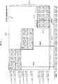
特許文献1には、図1に示す車両制御システムで使用される信頼性の高い通信ネットワークが記載されている。図1において、車両制御システム101は統合車両運動制御ECU(電子回路ユニット)110を有し、これによりハンドル151の回転角度を測定する操舵角度センサSen1と、ブレーキペダル152の押圧を測定するブレーキペダル位置センサSen2と、アクセルペダルの押圧を測定するアクセルペダル位置センサSen3と、運転手の要求を検知するセンサからの信号を用いて運転手の意図を解釈することにより、車両の状態を検知するセンサ(例えば、図示しないアクセルセンサ、ヨーレートセンサ、車輪速度センサなど)からの信号に基づいて車両の動きを中央で制御する。これらの要素は主要ネットワークNet100Aに接続され、ノードを構成している。本発明において、ノードとは、ネットワークに接続してデータを送受信できる構成要素を意味するが、それに限定されない。
主要ネットワークNet100Aにはさらに、車両の駆動システムを中央で制御する統合DBW(ドライババイワイヤ)制御ECU120と、ステアリングモータM1及びステアリングモータM5を制御するSBW(ステアバイワイヤ)−VGRドライバECU111と、ステアリングモータM2を制御するSBWドライバECU112と、ブレーキモータM3A〜M3Dを制御するBBW(ブレーキバイワイヤ)ドライバECU113A〜113Dと、サスペンションモータM4A〜M4Dを制御するEAS(電子アクティブサスペンション)ドライバECU114A〜114Dとが、アクチュエータ駆動ノードとして接続される。そこでは、ステアリングモータM1が前輪操舵力を起こし、モータM5がステアリングコラムに装備された可変ギアレシオ(VGR)機構に作用し、ステアリングモータM1が前輪操舵力を起こし、ブレーキモータM3A〜M3Dが4車輪に対するブレーキ力を発生し、サスペンションモータM4A〜M4Dが減衰力を調節する。
The main network Net100A further includes an integrated DBW (driver-by-wire)
主要ネットワークNet100Aには、車両の外の状態を検知するミリ波レーダ/カメラSen4と、エアバッグの展開を制御するエアバックECU115とが接続される。バックアップネットワークNet100Bには車両の安全運転に必要な最低限のノード、すなわち操舵角度センサSen1、ブレーキペダル位置センサSen2、SBW-VGRドライバECU111、及びBBWドライバECU113A〜113Dが接続される。
The main network Net100A is connected to a millimeter wave radar / camera Sen4 that detects a state outside the vehicle and an
統合DBW制御ECU120はネットワークNet101を介してエンジン制御ECU121、トランスミッション制御ECU122、モータ制御ECU123、及びバッテリ制御ECU124に接続する。統合車両運動制御ECU110はネットワークNet102を介して情報ゲートウェイ130と車体システムゲートウェイ140に接続し、これらの装置とデータを交換する。そこでは、情報ゲートウェイ130が、カーナビやその他の情報装置を制御するネットワークへのゲートウェイを提供し、車体システムゲートウェイ140がドアロック、サイドミラー、各種メーターなど、車体関係の装置を制御するネットワークへのゲートウェイを提供する。また、図示されていないが、エアバッグECU115の他端は、エアバッグの展開制御に必要な各種センサやアクチュエータを統合する安全関係のネットワークに接続する。
The integrated
統合車両運動制御ECU110は、車両の走行制御に必要な操舵角度やブレーキ力、駆動力などを、操舵角度センサSen1やブレーキペダル位置センサSen2、アクセルペダル位置センサSen3、車両の状態を検知するセンサ(例えば、アクセルセンサ、ヨーレートセンサ、車輪速度センサなど、図示せず)からの信号に基づいて計算する。そして、操舵角度指令を前輪SBW-VGRドライバECU111と後輪SBW-VGRドライバECU112に与え、ブレーキ力指令を4車輪のBBWドライバECU113A〜113Dに与え、駆動力指令を統合DBW制御ECU120に与える。統合DBW制御ECU120は駆動力指令を受信した後、エンジンやモータなどの動力源が生み出す駆動力をエネルギー効率を考慮した上で計算し、その結果得た駆動力指令をネットワークを介してエンジン制御ECU121やモータ制御ECU123などに送信する。統合車両運動制御ECU110は、運転手の要求を検知するセンサから得た情報だけでなく、車両の外の状態を検知するミリ波レーダー/カメラSen4から得た情報も用いることによって、後尾運転、車線維持運転、危険回避運転などの制御を行う。
The integrated vehicle
このような安全性を重視する車両制御システムにおいて、通信ネットワーク内のある特定のノードに障害が起きた場合、どのノードに障害が起きたかの情報を使って残りの正常なノードでバックアップ制御を行う必要がある。従って、障害が起きたノードを正確に特定し、残りの全ノード間でネットワークを介して通信しながら、どのノードに障害が起きたかについて一貫した情報を確保することが重要であり、結果としてノードステータスを監視する機能が必要になる。 In such a vehicle control system that places importance on safety, if a failure occurs in a specific node in the communication network, it is necessary to perform backup control on the remaining normal nodes using information on which node has failed. There is. Therefore, it is important to accurately identify the failed node and ensure consistent information about which node has failed while communicating over the network among all remaining nodes, and as a result A function to monitor status is required.
図2及び図3により特許文献1の制御方法について説明する。図2に示す車両制御システムは、ネットワークNet100を介して接続される複数のノード1(N1)、ノード2(N2)、……ノードn(Nn)で構成される。これらのノードはネットワークに接続された処理装置であり、ネットワークを介して情報を通信することができる。各ノードには車両に装備された様々な電子制御装置やアクチュエータドライバ、センサが含まれる。ネットワークNet100は多重通信ができるだけでなく、あるノードから、同ネットワークに接続された他のノード全部に同じ内容を同時発信する同報通信ができる。
The control method of
ノードN1、ノードN2、……ノードNn(以下ノードNxと呼ぶ)はそれぞれ、ノードステータス判定部x1(11、21、……n1)と、ステータス評価結果送受信部x2(12、22、……n2)と、障害ノード特定部x3(13、23、……n3)とを有する。なお、xの文字はノード番号(1、2、……n)を示し、以下同様に適用される。 Node N1, node N2,... Node Nn (hereinafter referred to as node Nx) are respectively node status determination unit x1 (11, 21,... N1) and status evaluation result transmission / reception unit x2 (12, 22,... N2). ) And a failure node specifying unit x3 (13, 23,..., N3). The letter x indicates a node number (1, 2,... N), and the same applies hereinafter.
ノードステータス判定部x1(11、21、……n1)は、そのノード自身のステータスを判定する自ノードステータス評価部x102(1102、2102、……n102)と、同ネットワーク内の他ノードのステータスを判定する他ノードステータス評価部x101(1101、2101、……n101)とを有する。 The node status determination unit x1 (11, 21,..., N1) is a node status evaluation unit x102 (1102, 2102,... N102) that determines the status of the node itself, and the status of other nodes in the network. And another node status evaluation unit x101 (1101, 2101,..., N101) for determination.
「自ノードステータス」とは自ノードの自己診断の結果であり、「他ノードステータス」とは、各他ノードから送信されたデータがその判定ノードから見て正しいかどうかに関するステータスである。例えば、ノード1がノード2の「他ノードステータス」が正常であることを判定するためには、ノード2のハードウェアが正常に作動しなければならず、また、ノード2で演算処理が正しく行われ、ノード2からノード1への通信が間違いなく行われなければいけない。例えば、通信周期ごとにインクリメントされる通し番号データを、全ノードが同報通信する構成が考えられる。この場合、あるノードから受信した通し番号データがインクリメントされていない場合は、そのノードの「他ノードステータス」は正常でないことが判定できる。
The “own node status” is a result of self-diagnosis of the own node, and the “other node status” is a status relating to whether data transmitted from each other node is correct as viewed from the determination node. For example, in order for the
ステータス評価結果送受信部x2(12、22、……n2)は、自ノードで得たノード評価結果と他ノードで得たノード評価結果を記憶するステータス評価結果記憶部x201(1201、2201、……n201)と、他ノードが判定したノードステータスを受信する受信処理装置x202(1202、2202、……n202)と、ノードステータス評価部x1(11、21、……n1)で判定されたノードステータス(自ノードが判定したノードステータス)を他ノードに送信するデータ送信部x203(1203、2203、……n203)とを有する。 The status evaluation result transmission / reception unit x2 (12, 22,..., N2) stores the status evaluation result storage unit x201 (1201, 2012,...) That stores the node evaluation result obtained at its own node and the node evaluation result obtained at another node. n201), the reception processing device x202 (1202, 2202,... n202) that receives the node status determined by the other node, and the node status determined by the node status evaluation unit x1 (11, 21,... n1) A data transmission unit x203 (1203, 2203,..., N203) that transmits the node status determined by the own node) to another node.
障害ノード特定部x3(13、 23、…… n3)は、自ノードで得たノード評価結果と、他ノードで得られ、ステータス評価結果送受信部x2で受信したノード評価結果とに基づいて、障害ノードを特定する。 The failure node identification unit x3 (13, 23,..., N3) determines the failure based on the node evaluation result obtained by the own node and the node evaluation result obtained by the other node and received by the status evaluation result transmission / reception unit x2. Identify the node.
図3に示すように、ネットワークNet100に接続されたノードはどれも、ステータス評価結果記憶部x201(1201、2201、……n201)を有する。例えば、ノード1のステータス評価結果記憶部1201のバッファ141に記憶された、ノード1の他ノードに関するステータス評価結果はネットワークNet100を介して全ての他ノードに送信され、ステータス評価結果記憶部x201のバッファx4x(n41、……n4n等)に記憶される。ノード2からノードnが行うステータス評価結果の送受信についても同様である。
As shown in FIG. 3, every node connected to the network Net100 has a status evaluation result storage unit x201 (1201, 2012,..., N201). For example, the status evaluation result related to the other node of
各ノードは評価結果データの多数決によって、他ノードのステータスを最終的に判定する。例えば、ノード1がノード2に障害があると判定したとしても、他ノード(ノード2〜ノードn)がノード2は正常であると判定していれば、ノード2よりノード1の方に障害があることを各ノードで正確に判定することができる。
Each node finally determines the status of the other nodes based on the majority of the evaluation result data. For example, even if
本発明に関する他の従来技術には非特許文献1がある。この論文では、検知した障害についての情報をペナルティ/リワードアルゴリズムを用いて蓄積し、一時的障害に対処する方法が提案されている。
There exists a
特許文献1のノードステータス監視方法における問題のひとつは、図4に示すように、各評価結果がnビットで構成される場合ステータス評価結果記憶部x201にはnノードのシステムにつきn×nビットが含まれるため、多数決作業の実行時間がノード数の2乗に比例して増加することである。さらに、評価結果ごとに必要な通信帯域幅はノード数に比例する。
One of the problems in the node status monitoring method of
また、ネットワーク内のノードが、ある特定のノードに障害があることを検知した場合、同ネットワークを使用するアプリケーションにその障害をいつ通知するかという問題がある。通知が迅速に行われた場合にはごく短期間で消え去る一時的な障害までアプリケーションに通知してしまう恐れがあり、障害をアプリケーションに通知するのが遅すぎると、特にブレーキなどの安全性において重要な要素に障害がある場合に危険な状況が発生する恐れがある。従って、アプリケーションへの迅速な通知と、関連性がある障害だけをアプリケーションに通知することとの間でバランスを見つける必要がある。従って、特許文献1では、ノードに障害があった通信周期ごとに数値がインクリメントされる障害カウンタと、障害カウンタ閾値を使用している。障害カウンタが障害カウンタ閾値を越えた場合、障害がアプリケーションに通知される。
In addition, when a node in the network detects that a certain node has a failure, there is a problem of when to notify the application using the network of the failure. If notification is made promptly, the application may be notified of a temporary failure that disappears in a very short period of time. If notification of the failure to the application is too late, it is particularly important for safety such as braking. A dangerous situation may occur if there are obstacles to various elements. Thus, a balance needs to be found between prompt notification to the application and notifying the application of only relevant faults. Therefore,
更に、あるノードに障害があるかどうかをノード各自でそれぞれ評価するため、ノードがアプリケーションに通知するタイミングに差が生じることがある。これは明らかに望ましくないためノード間の同期化が必要である。特許文献1では図5に示すようにこの問題に対処している。それまでの通信周期でノード3に障害があることが判定された場合に通信周期iでノード1とノード4の障害カウンタは8にインクリメントされる。あるエラーでノード2の障害カウンタは遅れを取っているため、5の値である。各通信周期で、ノードステータスデータと障害通知同期化フラグがノード間で送信される(フレームを送信)。通信周期i+1で、障害カウンタが再びインクリメントされる。通信周期i+2でノード1とノード4の障害カウンタが障害カウンタ閾値である10に達する。この状況で、ノード1とノード4からノード2に送信するフレームにおいて、ノード3に対する障害通知同期化フラグが立つ。ノード2はそのフレームを受信すると、自分の障害カウンタを10に補正し、ノード1やノード4と同様にノード3の障害をアプリケーションに通知する。
Furthermore, since each node evaluates whether or not a certain node has a failure, there may be a difference in the timing at which the node notifies the application. This is clearly undesirable and requires synchronization between nodes. In
この方法には、閾値が大きい場合に閾値に達するまでに長い時間がかかるという問題がある。システム全般の障害率によっては、閾値に達する以前にノード障害カウンタ値の大多数が破損してしまうかもしれない。この場合、障害通知のタイミングを一致させることができなくなってしまう。 This method has a problem that it takes a long time to reach the threshold when the threshold is large. Depending on the overall system failure rate, the majority of node failure counter values may be corrupted before the threshold is reached. In this case, failure notification timings cannot be matched.
本発明の目的は、上記従来技術の問題を解消して、通信ネットワーク内のノードステータスを監視する効率的な方法及び装置を提供することである。 The object of the present invention is to provide an efficient method and apparatus for monitoring the node status in a communication network by solving the above-mentioned problems of the prior art.
更に、本発明の目的は、構造安定性を向上させた通信ネットワーク内のノードステータス監視方法及び装置を提供することである。更に本発明の目的は、一時的障害を容認した上で迅速に通知を行う通信ネットワーク内のノードステータス監視方法及び装置を提供することである。 It is a further object of the present invention to provide a node status monitoring method and apparatus in a communication network with improved structural stability. It is a further object of the present invention to provide a node status monitoring method and apparatus in a communication network that allows notification immediately after accepting a temporary failure.
本発明の方法には、通信ネットワークをノードクラスタに分割するステップと、判定ノードの自ノードステータスと通信ネットワーク内の他ノードステータスとを診断することにより、通信ネットワーク内の各ノードで第1のノードステータスデータを判定するステップと、判定ノードから通信ネットワーク内の他ノードへ、判定ノードが属するクラスタのノードに関する第1のノードステータスデータを送信するステップと、通信ネットワーク内の他ノードから、送信ノードが属するクラスタのノードに関する第2のノードステータスデータを受信するステップと、判定した第1のノードステータスデータと、通信ネットワーク内の他ノードから受信した第2のノードステータスデータとに基づいて、通信ネットワーク内のノードに対するノードステータス評価データを判定するステップとを有する、通信ネットワーク内のノードステータス監視方法が含まれる。 The method of the present invention includes a step of dividing a communication network into node clusters, and diagnosing a self-node status of a determination node and a status of other nodes in the communication network, so that each node in the communication network has a first node. A step of determining status data; a step of transmitting first node status data relating to a node of a cluster to which the determination node belongs from the determination node to another node in the communication network; Based on the step of receiving second node status data relating to the nodes of the cluster to which it belongs, the determined first node status data, and the second node status data received from other nodes in the communication network, Against the node of And a determining over de status evaluation data includes node status monitoring method in a communication network.
上記の方法により、判定ノードが属するクラスタのノードに関する第1のノードステータスデータだけを送信し、送信ノードが属するクラスタのノードに関する第2のノードステータスデータだけを受信するため、通信情報量が提言されるため従来技術と比較して少ない通信帯域幅で足りるとともに、クラスタ監視方法を実施するために必要な時間が少なくてすむ。 By the above method, only the first node status data related to the node of the cluster to which the determination node belongs is transmitted, and only the second node status data related to the node of the cluster to which the transmission node belongs is received. Therefore, a communication bandwidth that is smaller than that of the prior art is sufficient, and less time is required to implement the cluster monitoring method.
上記方法に対し、ある実施形態においては、受信ノードで、受信ノードが属さないクラスタのノードから、第2のノードステータスデータを受信するステップと、そのクラスタに属する少なくとも1つのノードステータスを診断することにより、受信ノードで第1のノードステータスデータを判定するステップと、 第1のノードステータスデータが第2のノードステータスデータと一致するかどうかを判定するステップと、第1のノードステータスデータが第2のノードステータスデータと一致しないことが判定された場合、受信ノードのステータスを障害ありと診断するステップとが含まれていてもよい。 For the above method, in an embodiment, at a receiving node, receiving second node status data from a node of a cluster to which the receiving node does not belong, and diagnosing at least one node status belonging to the cluster. To determine the first node status data at the receiving node, to determine whether the first node status data matches the second node status data, and the first node status data to the second A step of diagnosing the status of the receiving node as faulty may be included if it is determined that it does not match the node status data.
この場合は、ノードステータスデータをクラスタにまとめる方法を取っているため、あるクラスタのノードが有する見解と、そのクラスタの外にあるノードが有する見解にずれが生じる場合がある。クラスタ内のある特定ノードが正常に機能していることをそのクラスタ内のノード全部が判定した状況で、クラスタ外のノードがその特定ノードに障害があると判断しても、本発明ではクラスタ外のノードの方に障害があると見なす。これは不一致を解決する簡単で効率的な方法である。 In this case, since the node status data is grouped into a cluster, there may be a difference between the view of a node in a cluster and the view of a node outside the cluster. Even if a node outside the cluster determines that the specific node is faulty in a situation where all the nodes in the cluster have determined that a specific node in the cluster is functioning normally, in the present invention, It is assumed that there is a failure in the node. This is a simple and efficient way to resolve discrepancies.
更に本発明の方法には、第1のノードの自ノードステータスと、少なくとも1つの第2のノードステータスとを診断することにより、第1のノードで第1のノードステータスデータを判定するステップと、少なくとも1つの第2のノードに第1のノードステータスデータを通信周期で周期的に送信するステップと、少なくとも1つの第2のノードから第2のノードステータスデータを通信周期で周期的に受信するステップと、判定した第1のノードステータスデータと受信した第2のノードステータスデータとに基づいて、第1のノードでノードステータス評価データを判定するステップとを含む、通信ネットワーク内のノードステータス監視方法が含まれる。 The method further includes determining first node status data at the first node by diagnosing the first node's own node status and at least one second node status; Periodically transmitting first node status data to at least one second node in a communication cycle; and periodically receiving second node status data from at least one second node in a communication cycle. And a node status monitoring method in the communication network, comprising: determining node status evaluation data at the first node based on the determined first node status data and the received second node status data. included.
判定したノードステータス評価データに基づいて、ある特定のノードに障害があることを判定してもよい。この場合、この特定ノードに対する第1の障害カウンタが初期値化され、各通信周期でノードステータス評価データがその特定ノードに障害があることを示すたびに第1の障害カウンタがインクリメントされ、第1の障害カウンタ値がグループ内の他ノードに送信され、グループ内の他ノードから送信された、特定ノードに対する第2の障害カウンタ値が受信される。 Based on the determined node status evaluation data, it may be determined that a certain node has a failure. In this case, the first failure counter for the specific node is initialized, and the first failure counter is incremented each time the node status evaluation data indicates that the specific node has a failure in each communication cycle. Failure counter value is transmitted to the other node in the group, and the second failure counter value for the specific node transmitted from the other node in the group is received.
本発明の一態様によると更に、グループ内のノードの大多数の障害カウンタが有する障害カウンタ値を判定するステップと、判定された障害カウンタ値が第1の障害カウンタ値と異なる場合、第1の障害カウンタを補正するステップとが実行される。 According to an aspect of the invention, further, the step of determining a fault counter value possessed by a majority of fault counters of the nodes in the group, and if the determined fault counter value is different from the first fault counter value, And correcting the fault counter.
上記の方法では、ノードは、そのノードが果たす役割によって同時に第1のノードと第2のノードになり得る。第1のノードの第1のノードステータスデータは、第2のノードで第2のノードステータスデータとして受信される。この方法には更に、第1のノードが属するノードグループを規定するステップが含まれてもよい。グループはネットワーク内のノード全部や、あるクラスタに属するノード、複数のクラスタに属するノード、あるクラスタに属するノードの一部、またはその他の数のノードなどで構成できる。 In the above method, a node can be a first node and a second node at the same time depending on the role it plays. The first node status data of the first node is received at the second node as second node status data. The method may further include defining a node group to which the first node belongs. A group can be composed of all nodes in the network, nodes belonging to a cluster, nodes belonging to a plurality of clusters, a part of nodes belonging to a cluster, or other numbers of nodes.
上記の方法では、グループ内のノードの大多数の障害カウンタが有する値を判定するので、あるノードにエラーが起こった可能性が高い場合に、そのノードの第1の障害カウンタを補正できるようになる。このように、グループに参加しているノードは、現時点で正しい障害カウンタ値を共有するようになり、グループ内のノードの障害カウンタが破損することを防ぐ。 In the above method, since the value of the majority of the failure counters of the nodes in the group is determined, when there is a high possibility that an error has occurred in a certain node, the first failure counter of the node can be corrected. Become. In this way, the nodes participating in the group share the correct failure counter value at the present time, thereby preventing the failure counter of the nodes in the group from being damaged.
この方法において、ある実施形態では更に、第1の障害カウンタが既定の閾値に達した場合に、特定ノードの障害を、その通信ネットワークを使用するアプリケーションに通知するステップが含まれる。 In this method, an embodiment further includes the step of notifying an application using the communication network of the failure of a particular node when the first failure counter reaches a predetermined threshold.
これにより、ある障害があってその障害に関する別の障害がネットワークに存在する可能性が十分に高い場合に、その障害をアプリケーションに通知することができるようになる。 Accordingly, when there is a certain failure and there is a high possibility that another failure related to the failure exists in the network, the failure can be notified to the application.
更に本発明には、第1のノードの自ノードステータスと、少なくとも1つの第2のノードステータスとを診断することにより、第1のノードで第1のノードステータスデータを判定するステップと、少なくとも1つの第2のノードに第1のノードステータスデータを送信するステップと、少なくとも1つの第2のノードから第2のノードステータスデータを受信するステップと、判定した第1のノードステータスデータと受信した第2のノードステータスデータとに基づいて、第1のノードでノードステータス評価データを判定するステップとを有する、通信ネットワーク内のノードステータス監視方法において、送受信は通信周期で周期的に行われることを特徴とする方法が含まれる。 The present invention further includes determining first node status data at the first node by diagnosing its own node status of the first node and at least one second node status, and at least one Transmitting first node status data to two second nodes; receiving second node status data from at least one second node; determined first node status data and received first A node status monitoring method in a communication network, comprising: a step of determining node status evaluation data at a first node based on the node status data of 2, wherein transmission / reception is periodically performed at a communication cycle. The method is included.
複数のノードがノードステータスデータを判定するため、ノードAがノードBに対する第2のノードであると同時に、ノードBがノードAに対する第2のノードになることもあり得る。ノードステータス評価データに基づいて、ある特定のノードに障害があると判定してもよい。本発明の一態様によると、ある特定のノードがある既定数の通信周期間正常に機能した後に障害があることが検知された場合、機能停止カウンタが初期値化される。機能停止カウンタは、初期値化された後、各通信周期ごとにインクリメントされる。 It is possible that node B is the second node for node A at the same time that node A is the second node for node A because multiple nodes determine the node status data. Based on the node status evaluation data, it may be determined that a certain node has a failure. According to one aspect of the present invention, when it is detected that there is a failure after a certain node functions normally for a predetermined number of communication cycles, the function stop counter is initialized. The function stop counter is incremented every communication cycle after being initialized.
この方法には更に、機能停止カウンタが既定の閾値に達した場合、その通信ネットワークを使用するアプリケーションに特定ノードの障害を通知するステップが含まれてもよい。機能停止カウンタを使用することで、アプリケーションへ迅速に通知できるようになる。 The method may further include the step of notifying the application using the communication network of the failure of the specific node when the outage counter reaches a predetermined threshold. By using the function stop counter, the application can be notified quickly.
この方法には更に、好適な一実施形態において、特定ノードがそれ以前に既定回数の通信周期間正常に機能したことが検知された場合、機能停止カウンタをリセットするステップが含まれてもよい。
このように、機能停止カウンタが一時的な障害によって初期値化された可能性が十分に高い場合は、機能停止カウンタをリセットすることにより、一時的である可能性が高い障害についてアプリケーションに通知しないですむようになる。
The method may further include, in a preferred embodiment, resetting the outage counter if it is detected that the particular node has previously functioned normally for a predetermined number of communication cycles.
In this way, if it is highly likely that the outage counter has been initialized due to a temporary failure, resetting the outage counter will not notify the application of a failure that is likely to be temporary. I'm sorry.
本発明による上記の方法において、ノードは車両制御システムの車載装置であってもよい。本発明による方法のある実施形態でノードステータスは正常か障害ありのどちらかである。 In the above method according to the present invention, the node may be an in-vehicle device of a vehicle control system. In an embodiment of the method according to the invention, the node status is either normal or faulty.
本発明のノードステータス監視装置には更に、通信ネットワークをノードクラスタに分割する手段と、判定ノードの自ノードステータスと通信ネットワーク内の他ノードステータスとを診断することにより、通信ネットワーク内の各ノードで第1のノードステータスデータを判定する手段と、判定ノードから通信ネットワーク内の他ノードへ、判定ノードが属するクラスタのノードに関する第1のノードステータスデータを送信する手段と、通信ネットワーク内の他ノードから、送信ノードが属するクラスタのノードに関する第2のノードステータスデータを受信する手段と、判定した第1のノードステータスデータと通信ネットワーク内の他ノードから受信した第2のノードステータスデータとに基づいて、通信ネットワーク内のノードに対するノードステータス評価データを判定する手段とを有する、通信ネットワーク内のノードステータス監視装置が含まれる。この装置は、対応する本発明の方法と同じ利点を有する。 The node status monitoring apparatus of the present invention further includes means for dividing the communication network into node clusters, and diagnoses the own node status of the determination node and the status of other nodes in the communication network, so that each node in the communication network Means for determining first node status data; means for transmitting first node status data relating to a node of the cluster to which the determination node belongs; from the determination node to another node in the communication network; , Based on the means for receiving the second node status data relating to the nodes of the cluster to which the sending node belongs, the determined first node status data and the second node status data received from other nodes in the communication network, To nodes in the communication network And a means for determining node status evaluation data include node status monitoring device in a communication network. This device has the same advantages as the corresponding inventive method.
この装置には更に、ある実施形態で、受信ノードで、受信ノードが属さないクラスタのノードから第2のノードステータスデータを受信する手段と、そのクラスタに属する少なくとも1つのノードのステータスを診断することにより、受信ノードで第1のノードステータスデータを判定する手段と、第1のノードステータスデータが第2のノードステータスデータと一致するかどうかを判定する手段と、第1のノードステータスデータが第2のノードステータスデータと一致しないことが判定された場合、受信ノードのステータスを障害ありと診断する手段とが含まれる。これらの手段で不一致を簡単に解決することができる。 The apparatus further includes, in an embodiment, at the receiving node, means for receiving second node status data from a node of the cluster to which the receiving node does not belong, and diagnosing the status of at least one node belonging to the cluster. The means for determining the first node status data at the receiving node, the means for determining whether the first node status data matches the second node status data, and the first node status data are second Means for diagnosing the status of the receiving node as faulty when it is determined that the received status does not match the node status data. Inconsistencies can be easily resolved by these means.
更に本発明には、第1のノードの自ノードステータスと、少なくとも1つの第2のノードステータスとを診断することにより、第1のノードで第1のノードステータスデータを判定する手段と、少なくとも1つの第2のノードに第1のノードステータスデータを送信する手段と、少なくとも1つの第2のノードから第2のノードステータスデータを受信する手段と、判定した第1のノードステータスデータと受信した第2のノードステータスデータとに基づいて、第1のノードでノードステータス評価データを判定する手段とを含む、通信ネットワーク内のノードステータス監視装置において、送受信は通信周期で周期的に行われることを特徴とする装置が含まれる。 The present invention further includes means for determining first node status data at the first node by diagnosing the own node status of the first node and at least one second node status, and at least one Means for transmitting first node status data to two second nodes, means for receiving second node status data from at least one second node, received first node status data and received first node status data A node status monitoring apparatus in a communication network, wherein transmission and reception are periodically performed at a communication cycle. The node status monitoring device in the communication network includes means for determining node status evaluation data at a first node based on the node status data of 2. Is included.
この装置には更に、第1のノードが属するノードグループを規定する手段が含まれてもよい。この装置にはさらに、障害カウンタと、判定したノードステータス評価データに基づいて、ある特定ノードに障害があることを判定する手段と、その特定ノードに対する第1の障害カウンタを初期値化する手段と、ノードステータス評価データでその特定ノードに障害があると示された各通信周期ごとに第1の障害カウンタをインクリメントさせる手段と、グループ内の他ノードに第1の障害カウンタ値を送信する手段と、グループ内の他ノードからその特定ノードに対する第2の障害カウンタ値を受信する手段とが含まれてもよい。 The apparatus may further include means for defining a node group to which the first node belongs. The apparatus further includes a failure counter, means for determining that a specific node has a failure based on the determined node status evaluation data, and means for initializing a first failure counter for the specific node; Means for incrementing the first fault counter for each communication period indicated by the node status evaluation data that the specific node is faulty; means for sending the first fault counter value to other nodes in the group; Means for receiving a second failure counter value for the particular node from other nodes in the group.
本発明の一態様によると、この装置には更に、グループのノードの大多数の障害カウンタが有する障害カウンタ値を判定する手段と、判定された障害カウンタ値が第1の障害カウンタ値と異なる場合、第1の障害カウンタを補正する手段とが含まれる。この装置で、ノードの障害カウンタの破損を防げるようになる。 According to one aspect of the present invention, the apparatus further includes means for determining a failure counter value possessed by a majority of the failure counters of the nodes of the group, and when the determined failure counter value is different from the first failure counter value. Means for correcting the first fault counter. With this device, the failure counter of the node can be prevented from being damaged.
この装置には更に、第1の障害カウンタが既定の閾値に達した場合、その通信ネットワークを使用するアプリケーションに特定ノードの障害を通知する手段が含まれてもよい。 The apparatus may further include means for notifying an application using the communication network of a failure of a specific node when the first failure counter reaches a predetermined threshold.
更に本発明には、第1のノードの自ノードステータスと、少なくとも1つの第2のノードステータスとを診断することにより、第1のノードで第1のノードステータスデータを判定する手段と、少なくとも1つの第2のノードに第1のノードステータスデータを送信する手段と、少なくとも1つの第2のノードから第2のノードステータスデータを受信する手段と、判定した第1のノードステータスデータと受信した第2のノードステータスデータとに基づいて、第1のノードでノードステータス評価データを判定する手段とを有する、通信ネットワーク内のノードステータス監視装置において、送受信は通信周期で周期的に行われることを特徴とする装置が含まれる。 The present invention further includes means for determining first node status data at the first node by diagnosing the own node status of the first node and at least one second node status, and at least one Means for transmitting first node status data to two second nodes, means for receiving second node status data from at least one second node, received first node status data and received first node status data And a node status monitoring device in a communication network having means for determining node status evaluation data at the first node based on the node status data of 2. The transmission / reception is periodically performed at a communication cycle. Is included.
更にこの装置には、ノードステータス評価データに基づいて、ある特定のノードに障害があることを判定する手段と、機能停止カウンタと、特定ノードが既定回数の通信周期間正常に機能した後で、その特定ノードに障害があることが検知された場合、機能停止カウンタを初期値化する手段と、機能停止カウンタを初期値化した後、各通信周期ごとに機能停止カウンタをインクリメントさせる手段とが含まれてもよい。 Further, in this apparatus, a means for determining that there is a failure in a specific node based on the node status evaluation data, a function stop counter, and after the specific node functions normally for a predetermined number of communication cycles, When it is detected that there is a failure in the specific node, means for initializing the function stop counter and means for incrementing the function stop counter for each communication cycle after initializing the function stop counter May be.
更にこの装置には、機能停止カウンタが既定の閾値に達した場合、その通信ネットワークを使用するアプリケーションに特定ノードの障害を通知する手段が含まれてもよい。 Further, the apparatus may include means for notifying an application using the communication network of a failure of a specific node when the function stop counter reaches a predetermined threshold value.
ある好適な実施形態において、この装置には、特定ノードがそれまで既定回数の通信周期間正常に機能したことが検知された場合、機能停止カウンタをリセットする手段が含まれてもよい。 In a preferred embodiment, the apparatus may include means for resetting a function stop counter when it is detected that a specific node has functioned normally for a predetermined number of communication cycles.
機能停止カウンタに基づいて、一時的障害を無駄に通知することなく、アプリケーションへの迅速な通知が実現できる。 Based on the function stop counter, prompt notification to an application can be realized without wasteful notification of a temporary failure.
本発明による監視装置のある実施形態では、ノードは、車両制御装置の車載装置であってもよい。ある実施形態では、ノードステータスは正常か障害ありのどちらかである。 In an embodiment of the monitoring device according to the present invention, the node may be an in-vehicle device of a vehicle control device. In some embodiments, the node status is either normal or faulty.
本発明の方法と本発明の装置は、通常はコンピュータプログラムによって実行される。従って、本発明にはコンピュータプログラム製品も含まれ、そのコンピュータプログラム製品には、コンピュータ可読媒体と、データ処理装置のデータ処理手段によって処理される指示に対応する一連の構成要素という形態でコンピュータ可読媒体に記録されたコンピュータプログラムとが含まれる。それによって本発明の方法が実行され、または本発明の装置がデータ処理手段に形成される。 The method of the present invention and the apparatus of the present invention are usually executed by a computer program. Accordingly, the present invention also includes a computer program product that includes a computer readable medium and a series of components corresponding to instructions processed by the data processing means of the data processing device. Computer programs recorded on the computer. Thereby the method according to the invention is carried out or the device according to the invention is formed in the data processing means.
本発明は、ノードステータスを判定するノードが属するクラスタのノードに関する第1のノードステータスデータだけを送信し、送信ノードが属するクラスタのノードに関する第2のノードステータスデータだけを受信するため、従来技術と比較して少ない通信帯域幅で足りる。その上、ノードステータスを判定する方法を実施するために必要な時間を短縮することが出来る。 Since the present invention transmits only the first node status data related to the node of the cluster to which the node for determining the node status belongs, and receives only the second node status data related to the node of the cluster to which the transmission node belongs, Less communication bandwidth is sufficient. In addition, the time required to implement the method for determining node status can be reduced.
また、グループ内のノードの大多数の障害カウンタが有する値を判定するので、あるノードにエラーが起こった可能性が高い場合に、そのノードの第1の障害カウンタを補正できるようになる。このように、グループに参加しているノードは、現時点で正しい障害カウンタ値を共有するようになり、結果としてグループ内のノードの障害カウンタが破損することを防ぐ。 In addition, since the value of the majority of the failure counters of the nodes in the group is determined, when there is a high possibility that an error has occurred in a certain node, the first failure counter of that node can be corrected. As described above, the nodes participating in the group share the correct failure counter value at the present time, and as a result, the failure counters of the nodes in the group are prevented from being damaged.
さらに、このように機能停止カウンタが一時的な障害によって初期値化された可能性が十分に高い場合は、機能停止カウンタをリセットし、一時的である可能性が高い障害についてアプリケーションに通知しないですむようになる。 In addition, if it is highly likely that the outage counter was initialized due to a temporary failure, reset the outage counter and not notify the application about a failure that is likely to be temporary I will become
本発明の実施形態と詳細を、図を参照しながら以下に更に詳しく説明する。 Embodiments and details of the present invention will be described in more detail below with reference to the drawings.
〔クラスタ構造ネットワーク〕
以下に、本発明の実施例1を、図6〜図8を参照しながら説明する。図6において、実施例1による通信ネットワークのノードステータス監視装置600は、通信ネットワークをノードクラスタに分割するノードクラスタ分割手段610を有する。第1ノードステータスデータ判定手段620は、制定対象のノードである判定ノードの自ノードステータスと通信ネットワーク内の他ノードステータスとを診断することにより、通信ネットワーク内の各ノードで第1のノードステータスデータを判定する。
[Cluster structure network]
その後、送信手段630が、判定ノードが属するクラスタのノードに関する第1のノードステータスデータを判定ノードから通信ネットワーク内の他ノードに送信し、他ノードでは送信された第1のノードステータスデータが第2のノードステータスデータとして受信される。 Thereafter, the transmission means 630 transmits the first node status data related to the node of the cluster to which the determination node belongs from the determination node to the other nodes in the communication network, and the transmitted first node status data is the second Node status data.
さらに、受信手段640が、送信ノードが属するクラスタのノードに関する第2のノードステータスデータを通信ネットワーク内の他ノードから受信する。次いで、ノードステータス評価データ判定手段650が、判定した第1のノードステータスデータと、通信ネットワーク内の他ノードから受信した第2のノードステータスデータとに基づいて、通信ネットワーク内のノードに対するノードステータス評価データを判定する。 Further, the receiving means 640 receives second node status data related to the nodes of the cluster to which the transmitting node belongs from other nodes in the communication network. Next, the node status evaluation data determination means 650 evaluates the node status for the node in the communication network based on the determined first node status data and the second node status data received from another node in the communication network. Determine the data.
図7は、クラスタ構造ネットワークの一例を示す。クラスタ1の第1のノードを1−1と表示し、クラスタ1の第2のノードを1−2と表示し、以下同様に表示する。図7に見られるように、各クラスタがc個のノードで構成される場合、n個のノードは論理的にn/c個のクラスタに分割される。図示の例では、nがcで割り切れることを想定しているが、以下の説明は、cで割り切れないn個のノードを有するシステムにも適用することができる。
FIG. 7 shows an example of a cluster structure network. The first node of
図8に、各ノードのステータス評価結果記憶部x201(例えば図3に示すもの)に記憶されたノードステータスデータを示す。図8に見られるように、全ノードは各クラスタに対するc×c個のノードステータスデータ項目を記憶する。このシステムにはn/c個のクラスタがあるため、ステータス評価結果記憶部と通信帯域幅をn×cビットに減らすことができ、また多数決作業の実行時間をc/nに減らすことができる。 FIG. 8 shows node status data stored in the status evaluation result storage unit x201 (for example, one shown in FIG. 3) of each node. As can be seen in FIG. 8, all nodes store c × c node status data items for each cluster. Since there are n / c clusters in this system, the status evaluation result storage unit and the communication bandwidth can be reduced to n × c bits, and the execution time of the majority task can be reduced to c / n.
図8に示す空き領域は、実施例1が従来例の図4と比較して新たな計算作動力と通信帯域幅を得たことを示している。すなわち従来例のn×nビットに比べて、n×cビットのメモリしか割り当てる必要がない。図8に示すように、ノードに対するノードステータスデータに基づいて、多数決作業で全ノードに対するノードステータス評価データが判定される。
〔ノードステータス監視方法〕
図9に、実施例1の通信ネットワーク内の障害を判定するノードステータス監視方法を説明する。図9に示すように、ノード2−1は受信ノードであって、ノード2−1が属さないクラスタであるクラスタ1のノード1−1、ノード1−2、及びノード1−4から第2のノードステータスデータを受信しているが、ノード1−3からは第2のノードステータスデータを受信していない。従って、ノード2−1自身かノード1−3のどちらかに障害があると判定する。すなわち、ノード2−1はノード1−3のステータスを診断することによって第1のノードステータスデータを判定する。
The free space shown in FIG. 8 indicates that the first embodiment obtained new calculation operation force and communication bandwidth as compared with FIG. 4 of the conventional example. That is, it is only necessary to allocate an n × c bit memory compared to the conventional n × n bit. As shown in FIG. 8, node status evaluation data for all the nodes is determined by majority work based on the node status data for the nodes.
[Node status monitoring method]
FIG. 9 illustrates a node status monitoring method for determining a failure in the communication network according to the first embodiment. As shown in FIG. 9, the node 2-1 is a receiving node, and the nodes 1-1, 1-2, and 1-4 of the
図9の右側に示すように、ノード2−1はノード1−1、ノード1−2、及びノード1−4から受信した第2のノードステータスデータを評価する。「1」はノードが正常であることを表し、「0」はノードに障害があることを示す。「−」は何の情報も受信されなかったことである。図9の右側に見られるように、第2のノードステータスデータの第1ビットにノード1−1についての情報が含まれ、第2ビットにはノード1−2についての情報が、第3ビットにはノード1−3についての情報、第4ビットにはノード1−4についての情報が含まれているので、ノード1−1はノード2−1に、ノード1−1の見解によるとノード1−2、ノード1−3、およびノード1−4は正常に機能していることを伝えている。 As shown on the right side of FIG. 9, the node 2-1 evaluates the second node status data received from the node 1-1, the node 1-2, and the node 1-4. “1” indicates that the node is normal, and “0” indicates that the node has a failure. “-” Means that no information was received. As seen on the right side of FIG. 9, the first bit of the second node status data includes information about the node 1-1, the second bit contains information about the node 1-2, and the third bit contains information about the node 1-2. Is information about the node 1-3, and the fourth bit contains information about the node 1-4. Therefore, the node 1-1 is connected to the node 2-1, and according to the view of the node 1-1, the node 1- 2, node 1-3 and node 1-4 are reporting that they are functioning normally.
ノード2−1は第2のノードステータスデータを評価し、クラスタ内のノードの見解によると、そのクラスタではどのノードも正常に機能していることを判定する。しかし、ノード2−1はノード1−3から情報を受信しておらず、それはノード1−3かノード2−1のどちらかに障害があることを意味する。ノード2−1は第2のノードステータスデータからクラスタ1内のノードは全て正常に機能していることを導き出すので、ノード2−1はそれ自身に障害があることを結論づけることができる。つまり、ノード2−1は、第1のノードステータスデータが第2のノードステータスデータと一致しないことを判定し、よってそれ自身のステータスを障害ありと診断する。
Node 2-1 evaluates the second node status data and, according to the view of the nodes in the cluster, determines that any node in the cluster is functioning normally. However, the node 2-1 has not received information from the node 1-3, which means that either the node 1-3 or the node 2-1 has a failure. Since node 2-1 derives from the second node status data that all nodes in
以下に、本発明の実施例2の通信ネットワーク内のノードステータス監視装置及び方法を、図10〜図12を参照しながら説明する。図10において、ノードステータス監視装置1000は、第1ノードステータスデータ判定手段1001を有し、これは第1のノードの自ノードステータスと、少なくとも1つの第2のノードステータスとを診断することにより、第1のノードで第1のノードステータスデータを判定する。送信手段1003は第1のノードステータスデータを少なくとも1つの第2のノードに送信する。少なくとも1つの第2のノードからの第2のノードステータスデータは、受信手段1004で受信される。
The node status monitoring apparatus and method in the communication network according to the second embodiment of the present invention will be described below with reference to FIGS. In FIG. 10, the node
ノードステータス監視装置1000は更に、ノードステータス評価データ判定手段1002を有し、これは判定した第1のノードステータスデータと受信した第2のノードステータスデータとに基づいて、第1のノードでノードステータス評価データを判定する。送受信は通信周期で周期的に行われる。第1のノードが属するノードグループは、ノードグループを規定するグループ規定手段1005によって決められる。
The node
ノードステータス監視装置1000は更に、判定したノードステータス評価データに基づいてある特定のノードに障害があることを判定する特定ノード障害判定手段1006と、図示しない障害カウンタを有する。特定ノード障害判定手段1006である特定ノードに障害があることが判定された場合、ノードステータス監視装置1000の一部である、特定ノードに対する第1の障害カウンタを初期値化する障害カウンタ初期値化手段1007によって、その特定ノードに対する第1の障害カウンタが1に初期値化される。第1の障害カウンタは、ノードステータス評価データでその特定ノードに障害があると示された通信周期ごとに、障害カウンタインクリメント手段1008によってインクリメントされる。送信手段1003が第1の障害カウンタ値をグループ内の他ノードに送信し、受信手段1004で、特定ノードに対する第2の障害カウンタ値をグループ内の他ノードから受信する。
The node
ノードステータス監視装置1000は更に、グループ内のノードの大多数の障害カウンタが有する障害カウンタ値を判定する、障害カウンタ値判定手段1009を有する。障害カウンタ補正手段1010は、判定した障害カウンタ値が第1の障害カウンタ値と異なる場合、第1の障害カウンタを補正する。第1の障害カウンタが既定の閾値に達した場合、アプリケーション通知手段1011で、その通信ネットワークを使用するアプリケーションに特定ノードの障害を通知する。
The node
図11に、送信手段1003によって送信されるデータ構造の例を示す。データ構造にはノードステータスデータフィールド1110が含まれ、そのフィールド1110には診断された各ノードに対して1つずつサブフィールドが設けられている。更に、図示のデータ構造には障害通知同期化フラグフィールド1120が設けらている。この障害通知同期化フラグフィールド1120の各ビットは、ある特定のノードに障害があるかどうかを示す。障害があるかどうかについては、例えばアプリケーション通知手段1011で判定される。障害カウンタ値フィールド1130において、通信周期に基づいて特定ノードの障害カウンタ値が送信される。
FIG. 11 shows an example of a data structure transmitted by the
図12に示すように、周期kではノード1−1に対する障害カウンタ値が送信され、周期k+1ではノード1−2に対する障害カウンタ値が送信される。図12は、本発明実施例のクラスタリング概念を用いたネットワークシステムを例にしており、クラスタのノードに関する第1の障害カウンタ値はクラスタ内で送信される。しかし、図10〜図12に示す実施形態は、クラスタリング概念を使わないネットワークシステムにも適用できる。
As shown in FIG. 12, the failure counter value for the node 1-1 is transmitted in the cycle k, and the failure counter value for the node 1-2 is transmitted in the
通信帯域幅が更に必要になるが(すなわち、Pthが障害カウンタ値の閾値である場合のlog2 Pthビット)、破損した障害カウンタを持つノードの数が増えすぎる前に、例えばビット反転などの理由によるノードの障害カウンタ値の間違いを補正することができる。 More communication bandwidth is needed (ie log2 Pth bits when Pth is the threshold of the fault counter value), but for reasons such as bit inversion before the number of nodes with corrupted fault counters increases too much It is possible to correct an error in the failure counter value of the node.
図13及び図14を参照しながら以下に、本発明の実施例3の通信ネットワーク内のノードステータス監視装置及び方法を説明する。 A node status monitoring apparatus and method in a communication network according to a third embodiment of the present invention will be described below with reference to FIGS. 13 and 14.
図13に示すノードステータス監視装置1300は、ノードステータスデータ判定手段1301を有し、これは第1のノードの自ノードステータスと少なくとも1つの第2のノードステータスとを診断することにより、第1のノードで第1のノードステータスデータを判定する。送信手段1303は第1のノードステータスデータを少なくとも1つの第2のノードに送信し、受信手段1304は少なくとも1つの第2のノードから第2のノードステータスデータを受信する。判定した第1のノードステータスデータと受信した第2のノードステータスデータとに基づいて、ノードステータス評価データ判定手段1302は、第1のノードでノードステータス評価データを判定する。送信手段1303と受信手段1304が行う送受信は、通信周期で周期的に行われる。
A node
ノードステータス監視装置1300は、さらにノードステータス評価データに基づいてある特定ノードに障害があることを判定する特定ノード障害判定手段1305と、図示しない機能停止カウンタを有する。特定ノードが既定回数の通信周期間正常に機能した後で、その特定ノードに障害があることが検知された場合に、機能停止カウンタ初期値化手段1306が機能停止カウンタを初期値化する。それから、機能停止カウンタインクリメント手段1307が、機能停止カウンタが初期値化された後に各通信周期ごとに機能停止カウンタをインクリメントさせる。
The node
図13に示すノードステータス監視装置1300は、さらにアプリケーション通知手段1308を有し、これは機能停止カウンタが既定の閾値に達した場合、その通信ネットワークを使用するアプリケーションに特定ノードの障害を通知する。機能停止カウンタリセット手段1309は、特定ノードがそれ以前に既定回数の通信周期間正常に機能したことが検知された場合、機能停止カウンタを0にリセットする。
The node
図14に3つのシナリオを用いて、障害カウンタと比較した機能停止カウンタの動作を説明する。機能停止カウンタは、障害カウンタと同様に、第1のノードステータスデータだけでなく第1及び第2のノードステータスデータに基づいて取り扱われる。しかし、下記の図14の説明では簡素化のため受信側の障害は考慮せず、障害は送信ノードが原因であると推定する。 The operation of the function stop counter compared with the fault counter will be described using three scenarios in FIG. Similar to the failure counter, the function stop counter is handled not only based on the first node status data but also on the first and second node status data. However, in the description of FIG. 14 below, for the sake of simplicity, the failure on the receiving side is not considered, and the failure is estimated to be caused by the transmission node.
各シナリオ(例1〜例3)の第1列目において、○は通信周期でメッセージが正しく受信されたこと、すなわち、送信ノードが正常に機能していることを意味し、×はメッセージが正しく受信されなかったこと、すなわち送信ノードに障害があることを意味する。機能停止カウンタと障害カウンタの閾値は4であり、リセットする前に正しく行われる通信周期の既定回数は3である。これは、アプリケーションプログラムが、それまでに3回受信したメッセージに基づいて出力結果を計算するため、メッセージが連続して3回正しく受信されるまで機能停止カウンタが増え続けることを意味する。これは制御論理を実行するアプリケーションプログラムで頻繁に行われる。 In the first column of each scenario (Example 1 to Example 3), ○ means that the message was correctly received in the communication cycle, that is, the sending node is functioning normally, and × means that the message is correct. It means that it was not received, that is, there is a failure in the transmitting node. The threshold of the function stop counter and the failure counter is 4, and the default number of communication cycles that is correctly performed before resetting is 3. This means that since the application program calculates the output result based on the messages received three times so far, the function stop counter continues to increase until the messages are correctly received three times in succession. This is frequently done in application programs that execute control logic.
例1は永続的障害の発生した状態を示す。永続的障害は周期4から始まっている。このシナリオでは、障害カウンタと機能停止カウンタが同じように作動している。すなわち、障害カウンタと機能停止カウンタは周期4から始まって1ずつ増加する。周期7で、カウンタが閾値の4に達し、アプリケーションに通知される。
Example 1 shows a situation where a permanent failure has occurred. Permanent failure starts at
例2は障害が間欠的に発生した状態、つまり、障害が完全に解決することなく、ある周期で発生したり別の周期で消滅したりする場合に起きる事象を示す。最初の障害は周期4で発生している。機能停止カウンタがインクリメントし始め、周期7で閾値に達するため、アプリケーションには周期7で通知される。一方、障害カウンタは間欠的障害が起きる度にインクリメントされる。間欠的障害は周期4、5、8、および11で発生しているため、障害カウンタに基づいてアプリケーションに通知されるのは周期11までかかる。これは、間欠的障害の場合、潜在的に機能停止カウンタがアプリケーションへの迅速な通知を請け負うことを意味する。
Example 2 shows a state in which a failure occurs intermittently, that is, an event that occurs when a failure occurs in one cycle or disappears in another cycle without being completely resolved. The first failure occurs at
例3は、間欠的障害がごくまれにしか発生しない状態を示す。この場合は機能停止カウンタがリセットされる。最初の障害は周期3で発生し、障害カウンタと機能停止カウンタが1にインクリメントされる。機能停止カウンタは周期6になるまで毎周期インクリメントされるが、周期6でそのノードが過去3周期のあいだ正常に機能したことをシステムが認識するため、機能停止カウンタはゼロにリセットされる。次の障害は周期7で発生するが、そこで障害カウンタは2になり、機能停止カウンタは再び1に初期値化され、カウントをし始める。
Example 3 shows a situation where intermittent failures occur very rarely. In this case, the function stop counter is reset. The first failure occurs in
機能停止カウンタはインクリメントし続け、再びリセットされることなく周期10で4の値に達する。これは、周期10までにノードが3周期間正常に機能することがなかったためである。このため、周期10で機能停止カウンタに基づいてアプリケーションに通知される。同周期において、障害カウンタはまだ3の値しかない。次の障害は周期18まで起こらないため、障害カウンタに基づいてアプリケーションへ通知が行われるのは周期18になる。
The function stop counter continues to increment and reaches a value of 4 in
本実施形態や図面の説明に制限的な意味はなく、例示として理解されるべきである。請求項に記載された本発明の範囲を逸脱することなしに、様々な変更や修正が可能であることは明らかである。本実施形態で説明した特徴を一部変更した上で組み合わせて、ある特定の使用でのシナリオに最適化した実施形態を更に追加することが可能である。そのような変更が当業者に簡単に思いつく限り、それらの変更は上記実施形態によって開示されているものと見なす。 This embodiment and the description of the drawings are not limited and should be understood as examples. Obviously, various modifications and changes can be made without departing from the scope of the present invention as set forth in the claims. It is possible to further add an embodiment optimized for a scenario in a specific use by combining some of the features described in the present embodiment after being partially changed. As long as such modifications can be easily conceived by those skilled in the art, those modifications are considered to be disclosed by the above embodiments.
610:ノードクラスタ分割手段
620:第1ノードステータスデータ判定手段
630:第1ノードステータスデータ送信手段
640:第2ノードステータスデータ受信手段
650:ノードステータス評価データ判定手段
1001:第1ノードステータスデータ判定手段
1002:判定手段
1003:送信手段
1004:受信手段
1005:ノードグループ規定手段
1006:特定ノード障害判定手段
1007:障害カウンタ初期値化手段
1008:障害カウンタインクリメント手段
1009:障害カウンタ値判定手段
1010:障害カウンタ補正手段
1301:第1ノードステータスデータ判定手段
1302:判定手段
1303:送信手段
1304:受信手段
1305:特定ノード障害判定手段
1306:機能停止カウンタ初期値化手段
1307:機能停止カウンタインクリメント手段
1308:アプリケーション通知手段
1309:機能停止カウンタリセット手段
610: Node cluster dividing unit 620: First node status data determining unit 630: First node status data transmitting unit 640: Second node status data receiving unit 650: Node status evaluation data determining unit 1001: First node status data determining unit 1002: Determination means 1003: Transmission means 1004: Reception means 1005: Node group definition means 1006: Specific node failure determination means 1007: Failure counter initialization means 1008: Failure counter increment means 1009: Failure counter value determination means 1010: Failure counter Correction unit 1301: First node status data determination unit 1302: Determination unit 1303: Transmission unit 1304: Reception unit 1305: Specific node failure determination unit 1306: Function stop
Claims (8)
判定対象のノードである判定ノードの、自ノードステータスと前記判定ノードが属するクラスタ内の前記判定ノードを除くノードの他ノードステータスとを診断することにより前記通信ネットワークの各ノードクラスタ内の全てのノードを診断したノードステータスである第1のノードステータスデータを判定するステップと、
前記判定ノードから前記通信ネットワークに接続された全ての他ノードに、前記判定ノードが属するクラスタのノードに関する第1のノードステータスデータを送信するステップと、
前記通信ネットワークに接続された全ての他ノードのうちノードステータスを送信する送信ノードから送信される、前記送信ノードが属するクラスタ内の全てのノードに関するノードステータスである第2のノードステータスデータを受信するステップと、
判定した前記第1のノードステータスデータと前記通信ネットワーク内の他ノードから受信した前記第2のノードステータスデータとに基づいて、前記通信ネットワークに接続された全てのノードについて障害の有無を評価したノードステータス評価データを判定するステップ
とを含むことを特徴とする通信ネットワーク内のノードステータス監視方法。 Dividing a communication network having a plurality of nodes into a plurality of node clusters;
All nodes in each node cluster of the communication network by diagnosing its own node status and other node statuses of nodes other than the determination node in the cluster to which the determination node belongs, of the determination node that is a determination target node Determining first node status data that is a node status that diagnoses
Transmitting first node status data relating to a node of a cluster to which the determination node belongs to all other nodes connected to the communication network from the determination node;
Receives second node status data, which is node status related to all nodes in the cluster to which the transmission node belongs, transmitted from a transmission node that transmits node status among all other nodes connected to the communication network. Steps,
A node that evaluates the presence or absence of a failure for all the nodes connected to the communication network based on the determined first node status data and the second node status data received from another node in the communication network Determining a status evaluation data, and a node status monitoring method in a communication network.
他ノードからのノードステータスデータを受信する受信ノードで、前記受信ノードが属さないクラスタのノードから第2のノードステータスデータを受信するステップと、
前記クラスタの少なくとも1つのノードのステータスを診断することにより、前記受信ノードで第1のノードステータスデータを判定するステップと、
前記第1のノードステータスデータが前記第2のノードステータスデータと一致するかどうかを判定するステップと、
前記第1のノードステータスデータが前記第2のノードステータスデータと一致しないことが判定された場合、多数決作業に従って前記受信ノードのステータスを障害ありと診断するステップ
とを含むことを特徴とする通信ネットワーク内のノードステータス監視方法。 The node status monitoring method in a communication network according to claim 1,
Receiving second node status data from a node of a cluster to which the receiving node does not belong at a receiving node that receives node status data from another node; and
Determining first node status data at the receiving node by diagnosing the status of at least one node of the cluster;
Determining whether the first node status data matches the second node status data;
Diagnosing the status of the receiving node as faulty according to a majority task when it is determined that the first node status data does not match the second node status data. Node status monitoring method within.
Applications Claiming Priority (2)
| Application Number | Priority Date | Filing Date | Title |
|---|---|---|---|
| EP08009078.0A EP2119612B1 (en) | 2008-05-16 | 2008-05-16 | Monitoring a status of nodes of a communication network |
| EP08009078.0 | 2008-05-16 |
Related Child Applications (1)
| Application Number | Title | Priority Date | Filing Date |
|---|---|---|---|
| JP2013139395A Division JP5668800B2 (en) | 2008-05-16 | 2013-07-03 | Node status monitoring method and monitoring apparatus in communication network |
Publications (2)
| Publication Number | Publication Date |
|---|---|
| JP2009278615A JP2009278615A (en) | 2009-11-26 |
| JP5313023B2 true JP5313023B2 (en) | 2013-10-09 |
Family
ID=40227816
Family Applications (2)
| Application Number | Title | Priority Date | Filing Date |
|---|---|---|---|
| JP2009096779A Expired - Fee Related JP5313023B2 (en) | 2008-05-16 | 2009-04-13 | Node status monitoring method and monitoring apparatus in communication network |
| JP2013139395A Expired - Fee Related JP5668800B2 (en) | 2008-05-16 | 2013-07-03 | Node status monitoring method and monitoring apparatus in communication network |
Family Applications After (1)
| Application Number | Title | Priority Date | Filing Date |
|---|---|---|---|
| JP2013139395A Expired - Fee Related JP5668800B2 (en) | 2008-05-16 | 2013-07-03 | Node status monitoring method and monitoring apparatus in communication network |
Country Status (3)
| Country | Link |
|---|---|
| US (2) | US8243609B2 (en) |
| EP (1) | EP2119612B1 (en) |
| JP (2) | JP5313023B2 (en) |
Families Citing this family (15)
| Publication number | Priority date | Publication date | Assignee | Title |
|---|---|---|---|---|
| CN103370899B (en) * | 2011-02-14 | 2016-09-28 | 瑞典爱立信有限公司 | Wireless device, registrar and wireless device method for pre-configuration |
| JP5375905B2 (en) * | 2011-09-06 | 2013-12-25 | 株式会社デンソー | In-vehicle network system |
| US10430216B1 (en) * | 2012-08-23 | 2019-10-01 | Scale Computing Inc | Virtual machine automated selection |
| US10491458B2 (en) * | 2013-01-31 | 2019-11-26 | Dell Products L.P. | System and method for reporting peer-to-peer transfer events |
| CN103139016B (en) * | 2013-02-19 | 2017-09-22 | 浪潮电子信息产业股份有限公司 | A kind of method of high-availability cluster monitoring resource |
| US9559892B2 (en) * | 2014-04-16 | 2017-01-31 | Dell Products Lp | Fast node/link failure detection using software-defined-networking |
| US20160037366A1 (en) * | 2014-08-01 | 2016-02-04 | Cox Communications, Inc. | Detection and reporting of network impairments |
| WO2016039758A1 (en) * | 2014-09-11 | 2016-03-17 | Hewlett Packard Enterprise Development Lp | Non-minimum cost forwarding for packet-switched networks |
| FR3028633B1 (en) * | 2014-11-18 | 2017-12-15 | Bull | METHOD AND ORDER FOR DETECTING OCCURRENCE DYSFUNCTION IN LARGE COMPUTER INFRASTRUCTURES |
| US9722863B2 (en) * | 2015-01-13 | 2017-08-01 | International Business Machines Corporation | Isolating the sources of faults/potential faults within computing networks |
| EP3492999A1 (en) * | 2017-11-30 | 2019-06-05 | Siemens Aktiengesellschaft | Method of operating a communication system, communication system and communication participant |
| US10911342B2 (en) | 2018-11-30 | 2021-02-02 | Sap Se | Distributed monitoring in clusters with self-healing |
| CN110171472B (en) * | 2019-07-11 | 2023-07-07 | 吉林大学 | Dual-mode rear wheel active steering device |
| CN113282000A (en) * | 2021-04-30 | 2021-08-20 | 科华数据股份有限公司 | Fault diagnosis method and device of data center and dynamic loop monitoring system |
| US20230275820A1 (en) * | 2022-02-28 | 2023-08-31 | Juniper Networks, Inc. | Successful connects metrics for monitoring and control of wireless or wired networks |
Family Cites Families (6)
| Publication number | Priority date | Publication date | Assignee | Title |
|---|---|---|---|---|
| JP3252345B2 (en) * | 1995-09-11 | 2002-02-04 | 沖電気工業株式会社 | Processing signal protection circuit |
| EP1374052B1 (en) * | 2001-03-30 | 2006-08-30 | Tttech Computertechnik AG | Method for operating a distributed computer system |
| US7184421B1 (en) * | 2001-12-21 | 2007-02-27 | Itt Manufacturing Enterprises, Inc. | Method and apparatus for on demand multicast and unicast using controlled flood multicast communications |
| TWI235299B (en) * | 2004-04-22 | 2005-07-01 | Univ Nat Cheng Kung | Method for providing application cluster service with fault-detection and failure-recovery capabilities |
| JP4871687B2 (en) | 2005-10-03 | 2012-02-08 | 日立オートモティブシステムズ株式会社 | Vehicle control system |
| US20090328189A1 (en) * | 2008-05-05 | 2009-12-31 | Gm Global Technology Operations, Inc. | Secure wireless communication initialization system and method |
-
2008
- 2008-05-16 EP EP08009078.0A patent/EP2119612B1/en not_active Expired - Fee Related
-
2009
- 2009-04-13 JP JP2009096779A patent/JP5313023B2/en not_active Expired - Fee Related
- 2009-05-14 US US12/466,088 patent/US8243609B2/en not_active Expired - Fee Related
-
2012
- 2012-03-13 US US13/418,985 patent/US20120170464A1/en not_active Abandoned
-
2013
- 2013-07-03 JP JP2013139395A patent/JP5668800B2/en not_active Expired - Fee Related
Also Published As
| Publication number | Publication date |
|---|---|
| US20120170464A1 (en) | 2012-07-05 |
| JP2013211928A (en) | 2013-10-10 |
| EP2119612B1 (en) | 2013-09-11 |
| US8243609B2 (en) | 2012-08-14 |
| EP2119612A1 (en) | 2009-11-18 |
| JP2009278615A (en) | 2009-11-26 |
| JP5668800B2 (en) | 2015-02-12 |
| US20090285107A1 (en) | 2009-11-19 |
Similar Documents
| Publication | Publication Date | Title |
|---|---|---|
| JP5313023B2 (en) | Node status monitoring method and monitoring apparatus in communication network | |
| JP4871687B2 (en) | Vehicle control system | |
| JP4222154B2 (en) | Vehicle control system | |
| US20100218047A1 (en) | Method and device for error management | |
| JP5303617B2 (en) | Vehicle control system | |
| US20090040934A1 (en) | Distributed System | |
| US20080298256A1 (en) | Distributed System | |
| CN203094176U (en) | Distributed fault-tolerant unit of fault-tolerant real-time steering control system | |
| US8170750B2 (en) | Parametric remedial action strategy for an active front steer system | |
| JP5518810B2 (en) | Vehicle control device and vehicle control system | |
| US8041993B2 (en) | Distributed control system | |
| US20030184158A1 (en) | Method for operating a distributed safety-relevant system | |
| JP2022500312A (en) | Vehicle control architecture | |
| US10356203B2 (en) | Fault-tolerant operational group on a distributed network | |
| US8843218B2 (en) | Method and system for limited time fault tolerant control of actuators based on pre-computed values | |
| Bannatyne | Time triggered protocol-fault tolerant serial communications for real-time embedded systems | |
| Poledna et al. | Communication bus for automotive applications | |
| Shaheen et al. | A comparison of emerging time-triggered protocols for automotive X-by-wire control networks | |
| Bergmiller et al. | Probabilistic fault detection and handling algorithm for testing stability control systems with a drive-by-wire vehicle | |
| JP2018157268A (en) | Transmitter and receiver | |
| JP6527541B2 (en) | Transmitter | |
| Sakurai et al. | Design and Implementation of Middleware for Network Centric X-by-Wire Systems | |
| CN114655178A (en) | Vehicle braking system and vehicle braking method | |
| JP4301144B2 (en) | Network system and network system state detection method | |
| WO2018111272A1 (en) | Fault-tolerant operational group on a distributed network |
Legal Events
| Date | Code | Title | Description |
|---|---|---|---|
| A621 | Written request for application examination |
Free format text: JAPANESE INTERMEDIATE CODE: A621 Effective date: 20110630 |
|
| A977 | Report on retrieval |
Free format text: JAPANESE INTERMEDIATE CODE: A971007 Effective date: 20121122 |
|
| A131 | Notification of reasons for refusal |
Free format text: JAPANESE INTERMEDIATE CODE: A131 Effective date: 20121204 |
|
| A521 | Request for written amendment filed |
Free format text: JAPANESE INTERMEDIATE CODE: A523 Effective date: 20130204 |
|
| A131 | Notification of reasons for refusal |
Free format text: JAPANESE INTERMEDIATE CODE: A131 Effective date: 20130305 |
|
| A521 | Request for written amendment filed |
Free format text: JAPANESE INTERMEDIATE CODE: A523 Effective date: 20130425 |
|
| TRDD | Decision of grant or rejection written | ||
| A01 | Written decision to grant a patent or to grant a registration (utility model) |
Free format text: JAPANESE INTERMEDIATE CODE: A01 Effective date: 20130604 |
|
| A61 | First payment of annual fees (during grant procedure) |
Free format text: JAPANESE INTERMEDIATE CODE: A61 Effective date: 20130703 |
|
| R150 | Certificate of patent or registration of utility model |
Free format text: JAPANESE INTERMEDIATE CODE: R150 Ref document number: 5313023 Country of ref document: JP Free format text: JAPANESE INTERMEDIATE CODE: R150 |
|
| LAPS | Cancellation because of no payment of annual fees |