JP5302190B2 - Audio decoding apparatus, audio decoding method, program, and integrated circuit - Google Patents
Audio decoding apparatus, audio decoding method, program, and integrated circuit Download PDFInfo
- Publication number
- JP5302190B2 JP5302190B2 JP2009516175A JP2009516175A JP5302190B2 JP 5302190 B2 JP5302190 B2 JP 5302190B2 JP 2009516175 A JP2009516175 A JP 2009516175A JP 2009516175 A JP2009516175 A JP 2009516175A JP 5302190 B2 JP5302190 B2 JP 5302190B2
- Authority
- JP
- Japan
- Prior art keywords
- frame
- section
- time signal
- correction
- output
- Prior art date
- Legal status (The legal status is an assumption and is not a legal conclusion. Google has not performed a legal analysis and makes no representation as to the accuracy of the status listed.)
- Expired - Fee Related
Links
Images


Classifications
-
- G—PHYSICS
- G10—MUSICAL INSTRUMENTS; ACOUSTICS
- G10L—SPEECH ANALYSIS OR SYNTHESIS; SPEECH RECOGNITION; SPEECH OR VOICE PROCESSING; SPEECH OR AUDIO CODING OR DECODING
- G10L19/00—Speech or audio signals analysis-synthesis techniques for redundancy reduction, e.g. in vocoders; Coding or decoding of speech or audio signals, using source filter models or psychoacoustic analysis
- G10L19/005—Correction of errors induced by the transmission channel, if related to the coding algorithm
-
- G—PHYSICS
- G10—MUSICAL INSTRUMENTS; ACOUSTICS
- G10L—SPEECH ANALYSIS OR SYNTHESIS; SPEECH RECOGNITION; SPEECH OR VOICE PROCESSING; SPEECH OR AUDIO CODING OR DECODING
- G10L19/00—Speech or audio signals analysis-synthesis techniques for redundancy reduction, e.g. in vocoders; Coding or decoding of speech or audio signals, using source filter models or psychoacoustic analysis
- G10L19/02—Speech or audio signals analysis-synthesis techniques for redundancy reduction, e.g. in vocoders; Coding or decoding of speech or audio signals, using source filter models or psychoacoustic analysis using spectral analysis, e.g. transform vocoders or subband vocoders
Abstract
Description
本発明は、オーディオ復号装置、オーディオ復号方法、プログラム及び集積回路に関し、特に、互いに重複する区間を含む複数のフレーム区間に分割された時間信号が、それぞれ符号化された複数のフレームデータを含むオーディオストリームを復号するオーディオ復号装置に関する。 The present invention relates to an audio decoding device, an audio decoding method, a program, and an integrated circuit, and in particular, an audio including a plurality of frame data in which time signals divided into a plurality of frame sections including overlapping sections are encoded. The present invention relates to an audio decoding apparatus for decoding a stream.
近年、マルチチャンネルオーディオの再生装置が整備されつつあり、マルチチャンネルに対するニーズが高まっている。そのため、MPEG(Moving Picture Experts Group)オーディオ規格において、MPEG Surroundと呼ばれるマルチチャンネル信号の符号化技術が規格化された。MPEG Surroundはマルチチャンネル信号の臨場感を維持したまま、マルチチャンネル信号をモノラル又はステレオの信号に符号化する。当該モノラル又はステレオの信号は、従来の放送又は配信によりオーディオ復号装置を備える再生装置に放送又は配信される。オーディオ復号装置は、当該モノラル又はステレオの信号をマルチチャンネル信号に復号する(例えば、非特許文献1参照)。 In recent years, multi-channel audio playback devices are being developed, and the need for multi-channels is increasing. Therefore, in the MPEG (Moving Picture Experts Group) audio standard, a multi-channel signal encoding technique called MPEG Surround has been standardized. MPEG Surround encodes a multi-channel signal into a monaural or stereo signal while maintaining the presence of the multi-channel signal. The monaural or stereo signal is broadcast or distributed to a playback device including an audio decoding device by conventional broadcasting or distribution. The audio decoding device decodes the monaural or stereo signal into a multi-channel signal (see, for example, Non-Patent Document 1).
このMPEG Surroundは、従来のマルチチャンネル符号化技術であるAC3(Dolby Digital、Audio Code number 3)及びDTS(Digital Theater Systems)よりもビットレートが低く、かつ従来のAAC(Advanced Audio Coding)及びAAC+SBR(Spectral Band Replication)といった符号化技術と互換性を保っているため、デジタルラジオ又はワンセグ放送などの移動体放送に用いられることが予想される。 This MPEG Surround has a bit rate lower than the conventional multi-channel coding techniques AC3 (Dolby Digital, Audio Code number 3) and DTS (Digital Theater Systems), and the conventional AAC (Advanced Audio CodingR). Since compatibility with an encoding technology such as (Spectral Band Replication) is maintained, it is expected to be used for mobile broadcasting such as digital radio or one-segment broadcasting.
ここで、一般的なオーディオ復号装置を、図1を用いて説明する。 Here, a general audio decoding apparatus will be described with reference to FIG.
図1に示す従来のオーディオ復号装置10は、ストリーム100を復号することで出力波形106を生成する。
The conventional
ストリーム100は、オーディオ符号化装置によってオーディオ信号が符号化されたビットストリームであり、一般に複数のアクセス単位によって構成される。このストリームのアクセス単位を以後フレームと呼ぶことにする。また、フレームに含まれる符号化されたオーディオ信号をフレームデータと呼ぶことにする。フレームデータは、原音(符号化前のオーディオ信号)が所定の区間ごとに符号化されたデータであり、当該所定の区間をフレーム区間と呼ぶことにする。
The
オーディオ復号装置10は、デコード部101と、直交変換部103と、出力部105とを備える。
The
デコード部101は、ストリーム100の文法解析を行い、フレーム単位で、ハフマン符号の復号及び逆量子化を行うことで、スペクトル係数102を生成するオーディオデコーダである。
The
直交変換部103は、フレーム単位で、スペクトル係数102をデコード部101で決められた変換アルゴリズムに基づいて時間信号104に変換する。
The
出力部105は、時間信号104から出力波形106を生成する。
The
また、従来のオーディオ復号装置10では、デコード部101でエラーが発生した際には、エラーが発生したフレーム(以下、エラーフレームと呼ぶ)の時間信号104を0でクリアするミュート処理、又は過去の時間信号104を繰り返し用いるリピート処理が行われる。
Further, in the conventional
また、エラーが発生したフレーム区間(以下、エラーフレーム区間と呼ぶ)の前後の時間信号からエラーフレーム区間の時間信号を補間することで、連続性を維持した補間を行うオーディオ復号装置も知られている(例えば、特許文献1参照)。
しかしながら、デジタルテレビなどに対する非移動体放送と比べ、移動体放送ではエラーが頻繁に発生することが予想される。エラーが頻繁に発生すると、従来のオーディオ復号装置10では、ミュート処理又はリピート処理が頻繁に繰り返される。これにより、ユーザーが不快に感じる可能性が高くなる。
However, it is expected that errors occur more frequently in mobile broadcasts than in non-mobile broadcasts for digital televisions and the like. If errors frequently occur, the conventional
また、特許文献1記載のオーディオ復号装置のように、前後のフレームからエラーフレーム区間を合成した場合にもリピート処理の様に信号の位相が合わず、ノイズを知覚する可能性がある。これにより、ユーザーが不快に感じる可能性が高くなる。
In addition, as in the audio decoding device described in
本発明は、このような従来の問題点を補うため、前後フレームとの連続性を維持したままエラーフレームを補間することで、ユーザーの不快感を低減できるオーディオ復号装置、オーディオ復号方法、プログラム及び集積回路を提供することを目的とする。 In order to compensate for such a conventional problem, the present invention interpolates an error frame while maintaining continuity with the preceding and succeeding frames, thereby reducing an uncomfortable feeling of the user, an audio decoding method, a program, and An object is to provide an integrated circuit.
上記の課題を解決するため、本発明に係るオーディオ復号装置は、隣接するフレーム区間の間で互いに重複する区間を含む複数のフレーム区間に分割された時間信号がそれぞれ符号化された複数のフレームデータを含むオーディオストリームを復号するオーディオ復号装置であって、前記オーディオストリームを前記フレームデータ単位でスペクトル係数に復号し、当該フレームデータを復号できない場合にエラー情報を出力するデコード手段と、前記スペクトル係数を前記フレーム区間単位の時間信号に変換する直交変換手段と、前記デコード手段により前記エラー情報が出力された場合、当該エラー情報が出力されたフレーム区間と当該フレーム区間に隣接するフレーム区間とが重複する区間内であり、かつ当該隣接するフレーム区間の中央部分の区間である基準区間の時間信号に基づき補正時間信号を生成する補正手段と、前記補正時間信号を前記エラー情報が出力されたフレーム区間の時間信号として用いたうえで、複数のフレーム区間の時間信号を合成することで、出力波形を生成する出力手段とを備える。 In order to solve the above-described problem, an audio decoding device according to the present invention provides a plurality of frame data obtained by encoding time signals divided into a plurality of frame sections including sections overlapping each other between adjacent frame sections. An audio decoding device for decoding an audio stream including: decoding means for decoding the audio stream into spectral coefficients in units of frame data and outputting error information when the frame data cannot be decoded; and the spectral coefficients When the error information is output by the orthogonal transform unit that converts the time signal in the frame section and the decoding unit, the frame section in which the error information is output overlaps with the frame section adjacent to the frame section. Within the section and of the adjacent frame section A correction means for generating a correction time signal based on a time signal of a reference section which is a central section, and a plurality of frame sections after using the correction time signal as a time signal of a frame section in which the error information is output Output means for generating an output waveform by synthesizing these time signals.
この構成によれば、本発明に係るオーディオ復号装置は、エラーが発生したフレーム区間に残っている時間信号を参照することで、エラーが発生したフレームの時間信号の波形に近い補正時間信号を生成し、生成した補正時間信号を出力波形に合成できる。これにより、本発明に係るオーディオ復号装置は、前後フレームとの連続性を維持したままエラーフレームを補間することで、ユーザーの不快感を低減できる。 According to this configuration, the audio decoding apparatus according to the present invention generates a correction time signal close to the waveform of the time signal of the frame in which the error has occurred by referring to the time signal remaining in the frame section in which the error has occurred. Then, the generated correction time signal can be synthesized with the output waveform. As a result, the audio decoding apparatus according to the present invention can reduce user discomfort by interpolating the error frame while maintaining continuity with the previous and subsequent frames.
さらに、本発明に係るオーディオ復号装置は、エラーが発生したフレーム区間の時間信号のうち、隣接するフレーム区間の中央部分の時間信号を用いて、補正時間信号を生成する。ここで、各フレーム区間の中央部分の時間信号は、両端部分の時間信号に比べて、原音(符号化前かつ分割前の時間信号)の情報を多く含んでいる。よって、本発明に係るオーディオ復号装置は、エラーが発生したフレーム区間の時間信号の波形により近い波形の補正時間信号を生成できる。 Furthermore, the audio decoding apparatus according to the present invention generates a correction time signal using a time signal in the central part of an adjacent frame section among time signals in a frame section in which an error has occurred. Here, the time signal in the center part of each frame section includes more information of the original sound (time signal before encoding and before division) than the time signal at both ends. Therefore, the audio decoding apparatus according to the present invention can generate a correction time signal having a waveform closer to the waveform of the time signal in the frame section in which the error has occurred.
また、前記補正手段は、前記基準区間の時間信号と、前記出力手段により既に生成された前記出力波形との相関値を算出し、算出した相関値が最も大きい前記出力波形を切り出すことで前記補正時間信号を生成してもよい。 The correction means calculates a correlation value between the time signal of the reference interval and the output waveform already generated by the output means, and cuts out the output waveform having the largest calculated correlation value, thereby correcting the correction. A time signal may be generated.
この構成によれば、本発明に係るオーディオ復号装置は、基準区間の時間信号に類似する補正時間信号を生成できる。 According to this configuration, the audio decoding apparatus according to the present invention can generate a correction time signal similar to the time signal of the reference section.
また、前記各フレーム区間は、それぞれ同じ時間長の第1区間、第2区間、第3区間及び第4区間からなり、前記隣接するフレーム区間の中央部分の区間は、前記隣接するフレーム区間の前記第2区間又は前記第3区間であってもよい。 Each frame section includes a first section, a second section, a third section, and a fourth section having the same time length, and the section of the central portion of the adjacent frame sections is the section of the adjacent frame section. It may be the second section or the third section.
また、前記補正手段は、前記算出した相関のうち最も強い相関値が予め定められた第1の値より大きいか否かを判定し、当該相関値が前記第1の値より大きい場合、前記補正時間信号を生成し、当該相関値が前記第1の値より小さい場合、前記補正時間信号を生成しなくてもよい。 The correction means determines whether or not the strongest correlation value among the calculated correlations is greater than a predetermined first value. If the correlation value is greater than the first value, the correction is performed. When a time signal is generated and the correlation value is smaller than the first value, the correction time signal may not be generated.
この構成によれば、本発明に係るオーディオ復号装置は、基準区間の時間信号と、出力波形との相関値が第1の値より小さい場合には、エラーが発生した時間信号の補正を行わない。これにより、本発明に係るオーディオ復号装置は、時間信号にアタック成分が含まれている場合、つまり補正を行うことで逆に音質が劣化する場合には補正を中止できる。 According to this configuration, the audio decoding device according to the present invention does not correct the time signal in which the error has occurred when the correlation value between the time signal in the reference section and the output waveform is smaller than the first value. . Thus, the audio decoding device according to the present invention can stop the correction when the time signal includes an attack component, that is, when the sound quality is deteriorated by performing the correction.
また、前記補正手段は、前記基準区間の出力波形のスペクトルを算出し、算出したスペクトルにおいて、高域のエネルギーの低域のエネルギーに対する比が予め定められた第2の値より大きいか否かを判定し、当該比が前記第2の値より小さい場合、前記補正時間信号を生成し、当該比が前記第2の値より大きい場合、前記補正時間信号を生成しなくてもよい。 Further, the correction means calculates a spectrum of the output waveform of the reference section, and in the calculated spectrum, whether or not the ratio of the high frequency energy to the low frequency energy is greater than a predetermined second value. If the ratio is smaller than the second value, the correction time signal is generated. If the ratio is larger than the second value, the correction time signal may not be generated.
この構成によれば、本発明に係るオーディオ復号装置は、基準区間の時間信号のスペクトルにおいて、高域のエネルギーが低域のエネルギーに比べて高い場合には、エラーが発生した時間信号の補正を行わない。これにより、本発明に係るオーディオ復号装置は、時間信号にアタック成分が含まれる場合、つまり補正を行うことで逆に音質が劣化する場合には補正を中止できる。 According to this configuration, the audio decoding device according to the present invention corrects the time signal in which an error has occurred when the high frequency energy is higher than the low frequency energy in the time signal spectrum of the reference interval. Not performed. Thereby, the audio decoding apparatus according to the present invention can stop the correction when the time signal includes an attack component, that is, when the sound quality is deteriorated by performing the correction.
また、前記補正手段は、前記相関値が最も大きい出力波形のスペクトルを算出し、算出したスペクトルにおいて、高域のエネルギーの低域のエネルギーに対する比が予め定められた第2の値より大きいか否かを判定し、当該比が前記第2の値より小さい場合、当該出力波形を切り出すことで前記補正時間信号を生成し、当該比が前記第2の値より大きい場合、前記補正時間信号を生成しなくてもよい。 Further, the correction means calculates a spectrum of the output waveform having the largest correlation value, and in the calculated spectrum, whether the ratio of the high frequency energy to the low frequency energy is larger than a predetermined second value. If the ratio is smaller than the second value, the correction time signal is generated by cutting out the output waveform. If the ratio is larger than the second value, the correction time signal is generated. You don't have to.
この構成によれば、本発明に係るオーディオ復号装置は、補正時間信号に用いる出力波形のスペクトルにおいて、高域のエネルギーが低域のエネルギーに比べて高い場合には、エラーが発生した時間信号の補正を行わない。これにより、本発明に係るオーディオ復号装置は、時間信号にアタック成分が含まれる場合、つまり補正を行うことで逆に音質が劣化する場合には補正を中止できる。 According to this configuration, the audio decoding device according to the present invention can detect the time signal in which an error has occurred when the high-frequency energy is higher than the low-frequency energy in the spectrum of the output waveform used for the correction time signal. Do not make corrections. Thereby, the audio decoding apparatus according to the present invention can stop the correction when the time signal includes an attack component, that is, when the sound quality is deteriorated by performing the correction.
なお、本発明は、このようなオーディオ復号装置として実現できるだけでなく、オーディオ復号装置に含まれる特徴的な手段をステップとするオーディオ方法として実現したり、そのような特徴的なステップをコンピュータに実行させるプログラムとして実現したりすることもできる。そして、そのようなプログラムは、CD−ROM等の記録媒体及びインターネット等の伝送媒体を介して流通させることができるのは言うまでもない。 Note that the present invention can be realized not only as such an audio decoding device but also as an audio method using characteristic means included in the audio decoding device as steps, or executing such characteristic steps in a computer. It can also be realized as a program to be executed. Needless to say, such a program can be distributed via a recording medium such as a CD-ROM and a transmission medium such as the Internet.
また、本発明は、このようなオーディオ復号装置の機能の一部又は全てを実現する集積回路としても実現できる。 The present invention can also be realized as an integrated circuit that realizes part or all of the functions of such an audio decoding device.
以上より、本発明は、前後フレームとの連続性を維持したままエラーフレームを補間することで、ユーザーの不快感を低減できるオーディオ復号装置、オーディオ復号方法、プログラム及び集積回路を提供できる。 As described above, the present invention can provide an audio decoding device, an audio decoding method, a program, and an integrated circuit that can reduce user discomfort by interpolating error frames while maintaining continuity with the preceding and following frames.
以下、本発明に係るオーディオ復号装置の実施の形態を、図面を参照しながら説明する。 Embodiments of an audio decoding apparatus according to the present invention will be described below with reference to the drawings.
(実施の形態1)
本発明の実施の形態1に係るオーディオ復号装置は、エラーフレーム区間に含まれる出力波形(時間信号)を用いて、エラーフレームの時間信号の波形に近い補正時間信号を生成し、生成した補正時間信号を出力波形に合成する。さらに、本発明に係るオーディオ復号装置は、エラーフレーム区間の時間信号のうち、原音の情報を多く含む、隣接するフレーム区間の中央部分の時間信号(出力波形)を用いて、補正時間信号を生成する。
(Embodiment 1)
The audio decoding apparatus according to
これにより、本発明に係るオーディオ復号装置は、前後フレームとの連続性を維持したままエラーフレームを補間することで、ユーザーの不快感を低減できる。 As a result, the audio decoding apparatus according to the present invention can reduce user discomfort by interpolating the error frame while maintaining continuity with the previous and subsequent frames.
まず、本発明の実施の形態1に係るオーディオ復号装置の構成を説明する。
First, the configuration of the audio decoding apparatus according to
図2は、本実施の形態1に係るオーディオ復号装置の構成を示す図である。 FIG. 2 is a diagram showing the configuration of the audio decoding apparatus according to the first embodiment.
図2に示すオーディオ復号装置20は、ストリーム200を復号することで、復号したオーディオ信号である出力波形206を生成する。
The
ストリーム200は、オーディオ符号化装置によってオーディオ信号が符号化されたオーディオビットストリームである。ストリーム200は、複数のフレームを含む。各フレームは、複数のフレーム区間に分割されたオーディオ信号が符号化されたフレームデータを含む。
The
オーディオ復号装置20は、デコード部201と、直交変換部203と、出力部205と、補正部208とを備える。
The
オーディオ復号装置20は、デコード部201でエラーが発生した場合に、デコード部201から得られるストリーム情報207と、エラーフレーム区間に含まれる出力波形206とに基づいてエラーフレームを復元する。
When an error occurs in the
デコード部201は、ストリーム200の文法解析を行ったうえで、フレーム単位で、ハフマン符号の復号及び逆量子化を行うことで、スペクトルデータであるスペクトル係数202を生成する。
The
また、デコード部201は、ストリーム情報207を出力する。
Further, the
ストリーム情報207は、デコード結果と、ストリームの特性とを含む情報である。ここで、デコード結果とは、デコード時にエラーが発生したか否かを示すエラーフラグの情報である。つまり、デコード部201は、フレームデータを復号できない場合に、エラーフラグを含むストリーム情報207を出力する。
The
また、ストリームの特性とは、MPEG−2 AACデコーダにおける、ストリーム長及びブロック長などの情報である。 The stream characteristics are information such as stream length and block length in the MPEG-2 AAC decoder.
直交変換部203は、デコード部201で決められた変換アルゴリズムに基づいて、フレーム単位で、スペクトル係数202を時間データである時間信号204に変換する。
The
出力部205は、直交変換部203で決められた変換アルゴリズムに基づいて、複数のフレームの時間信号204を合成することで、最終的な出力波形206を生成する。
The
補正部208は、ストリーム情報207にエラーフラグが含まれている場合に、出力波形206のエラーフレーム区間と過去又は未来の出力波形206に基づいてエラーフレームを補正するための時間信号である補正時間信号209を生成する。
The
また、出力部205は、補正部208により生成された補正時間信号209をエラーフレーム区間の時間信号として用いたうえで、複数のフレーム区間の時間信号204を合成することで、出力波形206を生成する。
The
以上のように構成されたオーディオ復号装置20の動作について説明する。
The operation of the
まず、MDCT(Modified Discrete Cosine Transform)によるオーディオ符号化について説明する。 First, audio encoding by MDCT (Modified Discrete Cosine Transform) will be described.
図3は、MDCTによるオーディオ符号化を説明するための図である。 FIG. 3 is a diagram for explaining audio encoding by MDCT.
図3に示すように、MDCTによる符号化では、元のオーディオ時間信号301は、複数のフレーム区間の時間信号301〜305に分割される。例えば、期間t1及びt2を合わした期間が1つのフレーム区間に対応し、期間t2及び期間t3を合わした期間が1つのフレーム区間に対応する。
As shown in FIG. 3, in the encoding by MDCT, the original
つまり、1つのフレーム区間は、隣接するフレーム区間に対して、互いに重複する区間を含む。例えば、時間信号301のフレーム区間と時間信号302のフレーム区間とは期間t2が重複する。
That is, one frame section includes sections overlapping each other with respect to adjacent frame sections. For example, the period t2 overlaps between the frame section of the
つまり、MDCTによる符号化では、期間t2の時間信号300は、時間信号301と時間信号302に分割され、期間t3の時間信号300は、時間信号302と時間信号303とに分割される。具体的には、期間t1及びt2の時間信号300に窓関数を掛けることで時間信号301が生成され、期間t2及びt3の時間信号300に窓関数を掛けることで時間信号302が生成される。
That is, in encoding by MDCT, the
次に、分割された時間信号301〜305は、それぞれ1つのフレームデータに符号化される。当該複数のフレームデータを含むストリーム200がオーディオ復号装置20に入力される。
Next, the divided
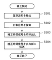
図4は、オーディオ復号装置20の動作の流れを示すフローチャートである。
FIG. 4 is a flowchart showing an operation flow of the
はじめに、デコード部201は、ストリーム200の文法解析を行ったうえで、フレーム毎に、ハフマン符号の復号及び逆量子化を行うことで、スペクトル係数202を生成する(S101)。
First, the
次に、直交変換部203は、オーディオコーデックで決められた変換アルゴリズムに基づいてスペクトル係数202を時間信号204に変換する(S102)。
Next, the
具体的には、MPEG−2 AACデコーダでは、2048点の振幅データを出力するIMDCT(逆MDCT:Inverse Modified Discrete Cosine Transform)が直交変換に用いられる。 Specifically, in the MPEG-2 AAC decoder, IMDCT (Inverse Modified Discrete Cosine Transform) that outputs 2048-point amplitude data is used for orthogonal transform.
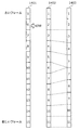
図5は、IMDCTを説明するための図である。なお、ここでは、正弦波に対して、MDCT及びIMDCTを行った場合の時間信号を例に示す。 FIG. 5 is a diagram for explaining the IMDCT. Here, a time signal when MDCT and IMDCT are performed on a sine wave is shown as an example.
図5において、時間信号310は、符号化前の1フレームに対応する時間信号である。つまり、時間信号310は、図3に示す時間信号301〜305に対応する。
In FIG. 5, a
ここで、1フレームの時間信号310は、それぞれ同じ時間長の4つの区間a〜dの信号からなる。
Here, the
直交変換部203は、スペクトル係数202にIMDCTを行うことで、時間信号311を生成する。符号化及び復号化の影響を無視すると、IMDCTの出力である時間信号311は、MDCTの入力である時間信号301〜305と下記の式(1)の関係が成立する。
The
Yn=IMDCT(MDCT(a、b、c、d))
=(a−bR、b−aR、c−dR、d−cR)・・・式(1)
Yn = IMDCT (MDCT (a, b, c, d))
= (A-bR, b-aR, c-dR, d-cR) Formula (1)
ここで、a、b、c、dは、それぞれ区間a〜dの信号であり、aR、bR、cR、dRは、それぞれ区間a、b、c、dの信号を時間軸で反転させた信号である。時間信号301〜305に対して式(1)を適用して得られる信号を時間信号301'〜305'とする。
Here, a, b, c, and d are signals in sections a to d, respectively, and aR, bR, cR, and dR are signals obtained by inverting the signals in sections a, b, c, and d on the time axis, respectively. It is. Signals obtained by applying Expression (1) to the
次に、直交変換部203は、時間信号311に窓関数を掛けることで時間信号204を生成する。
Next, the
デコード部201で当該フレームにエラーが発生していない場合(S103でNo)、つまりストリーム情報207にエラーフラグが含まれない場合、次に、出力部205は、直交変換のアルゴリズムに基づいて複数のフレームに対応する複数の時間信号204から出力波形206を生成する。具体的には、出力部205は、MPEG−2 AACデコーダでは、各時間信号204に含まれる2048点の振幅データを、それぞれ直前及び直後の時間データに含まれる振幅データと、1024点ずつ重ね合わせて合成することで、出力波形206を生成する(S105)。
When no error has occurred in the frame in the decoding unit 201 (No in S103), that is, when the error information is not included in the
つまり、出力部205は、図3に示す複数の時間信号301〜305に対して式(1)を適用した信号を加算することで、時間信号を復元する。例えば、出力部205は、時間信号301'の後半と、時間信号302'の前半を加算することで、期間t2の時間信号を生成し、時間信号302'の後半と、時間信号303'の前半を加算することで期間t3の時間信号を生成する。
That is, the
一方、デコード部201で当該フレームにエラーが発生した場合(S103でYes)、つまりストリーム情報207にエラーフラグが含まれる場合に、補正部208は、出力波形206のエラーフレーム区間とバッファリングされた出力波形206とに基づいてエラーフレームを補正する(S104)。
On the other hand, when an error occurs in the frame in the decoding unit 201 (Yes in S103), that is, when an error flag is included in the
一般に、オーディオ符号化技術で用いられているMDCT及びQMF(Quadrature Mirror Filters)といった直交変換では、連続したフレームのうちの1つのフレームでエラーが発生した場合においても、出力波形206のエラーフレーム区間に情報が含まれる。
In general, in orthogonal transforms such as MDCT and QMF (Quadrature Mirror Filters) used in audio coding technology, even if an error occurs in one of consecutive frames, an error frame section of the
図6は、エラーが発生した場合の時間信号204及び出力波形206のエンベロープ(包絡線)を示す図である。ここで、エンベロープとは、時間信号204及び出力波形206の概形を示す線である。
FIG. 6 is a diagram showing an envelope (envelope) of the
図6に示すように、連続するフレームのうち1つのフレームでエラーが発生した場合、当該エラーが発生したフレームに対応する時間信号204aの振幅値は0でクリアされる。しかしながら、上述したようにエラーフレーム区間t10の出力波形206は、エラーフレームの時間信号204aと、エラーフレームに隣接するフレームの時間信号204bの後半分及び時間信号204cの前半分を加算したものなので、エラーフレーム区間t10の出力波形206の振幅値は0にならない。つまり、エラーフレーム区間t10の出力波形206は、時間信号204bの後半分及び時間信号204cの前半分となる。
As shown in FIG. 6, when an error occurs in one of consecutive frames, the amplitude value of the
よって、補正部208は、エラーフレーム区間t10に含まれている情報、すなわち時間信号204bの後半分及び時間信号204cの前半分の振幅値のデータと似ている波形をバッファリングされた出力波形206から捜し出し、補正時間信号209を生成することが可能となる。
Therefore, the
以下、補正部208による補正処理(S104)を詳細に説明する。
Hereinafter, the correction process (S104) by the
図7は、補正部208による補正処理(S104)の流れを示すフローチャートである。
FIG. 7 is a flowchart showing the flow of the correction process (S104) by the
補正部208は、エラーフレーム区間と、エラーフレーム区間に隣接するフレーム区間とが重複する区間内であり、かつ当該隣接するフレーム区間の中央部分の区間である基準区間の時間信号に基づき補正時間信号209を生成する。
The
具体的には、補正部208は、基準区間の時間信号と、既に出力部205により生成された出力波形206との相関値を算出し、算出した相関値が最も大きい出力波形206を切り出すことで補正時間信号209を生成する。
Specifically, the
始めに、補正部208は、直前のフレーム区間から類似する波形の基準とする時間信号の波形である基準波形を抽出する(S501)。
First, the
ここで、エラーのために復元されなかった時間信号204aは、直前のフレームの時間信号204bの後半分と重複する区間の信号である。つまり、復元すべき時間信号204aの波形の前半分は、直前のフレームの時間信号204bの後半分の波形と似ていることが予想される。同様に、復元すべき時間信号204aの波形の後半分は、直後のフレームの時間信号204cの前半分の波形と似ていることが予想される。
Here, the
また、図5に示すように、符号化前の時間信号310に含まれる4つの区間a〜dの時間信号のうち、区間b及びcの時間信号は、窓関数の中央部分に位置するため原音(時間信号300)の情報を多く含む。区間a及びdの時間信号は、窓関数の両端部分に近いため原音(時間信号300)の情報が少ない。
Also, as shown in FIG. 5, among the time signals of the four sections a to d included in the
さらに、時間信号204を生成する際には、式(1)に示すように、区間a及びdの時間信号は、情報量が多い区間b及びcの時間信号を時間軸で反転させた信号であるbR及びcRで減算される。さらに、直交変換部203により、IMDCT後の時間信号311に窓関数が掛けられる。よって、時間信号204に含まれる区間b及びcの時間信号は、原音(時間信号300)の情報を多く含み、区間a及びdの時間信号は、原音(時間信号300)の情報が少ない。
Further, when generating the
そこで、補正部208は、基準波形として、原音の情報を多く含む区間b又はcの時間信号を基準波形として抽出する。
Therefore, the
図8〜図11は、補正部208による補正処理を説明するための図である。
8 to 11 are diagrams for explaining the correction processing by the
図8に示すように、補正部208は、エラーフレーム区間t10に含まれる出力波形206のうち、直前のフレームの区間cに対応する基準区間320の出力波形206を基準波形として抽出する。なお、補正部208は、直後のフレームの区間bに対応する基準区間321の出力波形206を基準波形として抽出してもよい。
As illustrated in FIG. 8, the
なお、補正部208は、基準区間320及び321の一部の区間に含まれる出力波形206を基準波形として抽出してもよい。
Note that the
また、基準区間320より前(図8における左側)の区間及び基準区間321より後(図8における右側)の区間では、出力波形206は完全に復元されているので、補正部208は、当該区間を含む区間の出力波形206を基準波形として抽出してもよい。
Further, since the
次に、補正部208は、基準波形を用いて、補正時間信号209の候補となる時間信号を含む対象区間323を探索する(S502)。
Next, the
補正部208は、図9に示すように、基準波形322と、バッファに蓄積された正常な出力波形206との相関をとり、相関の強い波形を含む対象区間323を探す。具体的には、補正部208は、出力波形206の各期間における相関度を算出することで、相関関数を算出する。補正部208は、算出した相関関数を用いて、相関度が最も高い対象区間323を探索する。つまり、補正部208は、算出した相関関数のピークを抽出する。ここで、相関度とは、波形(位相)の類似度合いである。つまり、対象区間323は、エラーにより消失した時間信号204aと、類似する音を含む区間である。
As illustrated in FIG. 9, the
次に、補正部208は、補正時間信号209を切り出す(S503)。具体的には、図10に示すように、対象区間323を含む1フレーム区間分の区間である切り出し区間324の出力波形206を切り出す。ここで、切り出し区間324は、基準区間320に対するエラーフレーム区間の相対位置に対応する、対象区間323に対する1フレーム区間である。ここでは、基準区間320は、エラーフレーム区間t10の先頭の区間なので、切り出し区間324は、対象区間323を先頭とする1フレーム区間である。
Next, the
次に、補正部208は、切り出した出力波形206に、MDCTと同様の窓関数を掛けることで、補正時間信号209を生成する。
Next, the
最後に、補正部208は、補正時間信号209を出力部205に転送する(S504)。
Finally, the
次に、出力部205は、エラーによって失われた時間信号204の代わりに補正時間信号209を用いて、複数のフレームの時間信号204及び補正時間信号209を合成することで、出力波形206の補間を行う(S105)。
Next, the
このように、本発明の実施の形態1に係るオーディオ復号装置20は、エラーが発生した時間信号204aとの相関が高い補正時間信号209で、出力波形206を補間する。これにより、出力波形206が連続的につながれるだけでなく、エラーフレームの位相が再現する可能性も高くなり、より高音質な補間が実現される。つまり、本発明の実施の形態1に係るオーディオ復号装置20は、前後フレームとの連続性を維持したままエラーフレームを補間できるので、ユーザーの不快感を低減できる。
As described above, the
なお、実施の形態1ではデコード時にエラーが発生した場合に常に補正を行う例を示したが、オーディオ復号装置20は、補正を行うか否かの判別を行ってもよい。
In the first embodiment, an example is shown in which correction is always performed when an error occurs during decoding, but the
図12は、出力波形206から補正を行うか否かを判断するオーディオ復号装置21の構成を示す図である。図12に示すオーディオ復号装置21は、図2に示すオーディオ復号装置20の構成に加え、さらに、補正制御部210を備える。なお、図2と同様の要素には同一の符号を付している。
FIG. 12 is a diagram illustrating a configuration of the
補正制御部210は、エラーフレーム区間の出力波形206に基づき補正の実行の有無を判別する。
The
図13は、補正制御部210の動作の流れを示すフローチャートである。
FIG. 13 is a flowchart showing an operation flow of the
始めに、補正制御部210は、エラーフレーム区間の出力波形206に対してスペクトル変換を行うことで、スペクトルを生成する(S1101)。
First, the
次に、補正制御部210は、生成したスペクトルの高域の低域に対するエネルギー比を算出する。補正制御部210、算出したエネルギー比と閾値を比較する(S1102)。
Next, the
エネルギー比が高い、すなわち、高域のエネルギーが低域と比べて高い場合には時間信号が定常的ではない可能性がある。このような場合は、エラーフレーム区間にアタック成分が含まれていることが考えられ、前のフレームの波形を用いて補間を行っても逆に音質が劣化する可能性がある。そのため、補正制御部210は、エネルギー比が閾値以上の場合(S1102でYes)には、補正を中止するように補正部208に指示する(S1104)。
If the energy ratio is high, that is, the energy in the high range is high compared to the low range, the time signal may not be stationary. In such a case, it is conceivable that an attack component is included in the error frame section, and even if interpolation is performed using the waveform of the previous frame, the sound quality may be deteriorated. Therefore, when the energy ratio is equal to or greater than the threshold (Yes in S1102), the
一方、エネルギー比が閾値以下の場合(S1102でNo)には、補正制御部210は、定常的な波形と判断し、補正部208に補正を継続させる(S1103)。
On the other hand, when the energy ratio is equal to or less than the threshold (No in S1102), the
なお、補正制御部210は、アタック成分が含まれているかの判定を、エラーフレーム区間に対してだけでなく、対象区間323、又は切り出し区間324に対し行ってもよい。
Note that the
また、定常性の判断を、補正部208がステップS502で算出する相関関数から判断してもよい。
Further, the determination of continuity may be determined from the correlation function calculated by the
図14は、本発明の実施の形態1の変形例における、補正部208によるステップS502の動作の流れを示すフローチャートである。
FIG. 14 is a flowchart showing a flow of the operation in step S502 by the
上述したように、始めに、補正部208は、エラーフレーム区間の基準波形322とバッファに蓄積された出力波形206との相関関数を算出し(S1201)、ピークを抽出する(S1202)。このとき、相関関数に強いピークが出現しているときはエラーフレーム区間の基準波形322と似ている信号が得られるが、ピークが弱い場合は、相関関数を算出する範囲の出力波形206にアタック成分が含まれていると考えられる。
As described above, first, the
そのため、補正部208は、ピークの値が閾値以下か否かを判定する(S1203)。補正部208は、ピークの値が閾値以下の場合(S1203でYes)には、相関が弱いと判断し、補正を中止する(S1204)。一方、ピークの値が閾値以上の場合(S1203でNo)には、補正部208は補間を継続する。
Therefore, the
また、上記実施の形態1ではエラーが発生したか否かを判断する情報としてストリーム情報207に含まれるエラーフラグを用いているが、ストリーム情報207に含まれるストリームのパラメータを用いてもよい。
In the first embodiment, the error flag included in the
図15は、ストリームのパラメータを用いて補間を行うか否かを判断するオーディオ復号装置22の構成を示す図である。図15に示すオーディオ復号装置22は、図2に示すオーディオ復号装置20の構成に加え、さらに、補正制御部211を備える。なお、図2と同様の要素には同一の符号を付している。
FIG. 15 is a diagram illustrating a configuration of the
補正制御部211は、ストリーム情報207に含まれるストリームのパラメータを用いて補正の実行の有無を判別する。
The
例えば、MPEG−2 AACでは、MDCTの長さに2048点と256点の2つが用いられており、当該情報はストリーム200内に記述されている。2048点の場合には、エンコード時に信号が定常的であると判断された可能性が高く、256点の場合には、信号にアタック成分が含まれている可能性が高い。
For example, in MPEG-2 AAC, two MDCT lengths of 2048 points and 256 points are used, and the information is described in the
デコード部201は、当該情報を含むストリーム情報207を出力する。
The
補正制御部211は、ストリーム情報207を参照し、MDCTの長さが2048点の場合には、補正部208に補正を行わせる。また、補正制御部211は、MDCTの長さが256点の場合には、補正部208に補正を行わせない。
The
また、上記説明において補正部208は、補間に用いる補正時間信号209を、過去の出力波形206から切り出されているが、出力波形206がバッファリングされている場合は、補正部208は、未来に相当する出力波形206から補正時間信号209を切り出してもよい。
In the above description, the
また、補正部208は、波形を切り出すのではなく、ピッチ波形のみを切り出し、ピッチ波形を重ね合わせることでエラーフレームを復元してもよい。
Further, the
また、補正部208は、波形を切り出すのではなく、切り出し区間のLPC(線形予測符号)分析を行い、エラーフレームにおいてLPC合成を行うことでエラーフレームを復元してもよい。
The
また、上記説明において、補正部208は、出力部205により合成された出力波形206を用いて補正時間信号209を生成するとしたが、合成前の時間信号204を用いて同様の処理を行ってもよい。同様に、補正制御部210も、合成前の時間信号204を用いて補正を行うか否かの判定を行ってもよい。
In the above description, the
(実施の形態2)
本発明の実施の形態2では、音声符号化方式にMPEGサラウンドを用いたデジタル放送受信機を例に説明する。
(Embodiment 2)
In the second embodiment of the present invention, a digital broadcast receiver using MPEG surround as an audio encoding method will be described as an example.
図16は、本発明の実施の形態2に係るデジタル放送受信機が備えるオーディオ復号装置の構成を示した図である。
FIG. 16 is a diagram showing a configuration of an audio decoding device provided in the digital broadcast receiver according to
図16に示すオーディオ復号装置30は、受信したビットストリーム信号1400を復号し、音声信号1403を出力する。オーディオ復号装置30は、デコード部1301と、バッファ部1302と、話速変換部1303と、エラー検出部1304と、出力速度設定部1305とを備える。
The
デコード部1301は、ビットストリーム信号1400を復号することで、ビットストリーム信号1400を音声信号1401に変換する。バッファ部1302はデコード部1301で変換された音声信号1401を蓄積し、蓄積する音声信号1402を出力する。エラー検出部1304はデコード部1301でエラーが発生したか否かを検出する。
The
話速変換部1303は、エラーが発生した場合、エラーが存在するフレームの音声信号1402を削除し、残りのフレームの音声信号1402を伸張し、伸張した音声信号1403を出力する。
When an error occurs, the speech
出力速度設定部1305は、話速変換部1303により伸張された時間長の総計が1フレームの長さを上回る場合、当該時間長の総計が1フレームの長さと合致するよう、伸張する最後のフレームの話速を調整する。また、出力速度設定部1305は、当該最後のフレーム以降は次にエラーが検出されるまで話速変換を行わない。
When the total time length expanded by the speech
図17は、オーディオ復号装置30におけるデータの流れを示す図である。なお、図16と同様の要素には同一の符号を付している。
FIG. 17 is a diagram showing a data flow in the
図17に示す個々のブロックはフレームを構成する時間領域の音声データを表し、番号が小さいものほど古いフレームを意味し、番号が大きいほど新しいフレームを意味するものとする。また、バッファ部1302の遅延時間を4フレームと仮定する。
Each block shown in FIG. 17 represents audio data in a time domain constituting a frame. A smaller number means an old frame, and a larger number means a new frame. Further, it is assumed that the delay time of the
ここで第6フレームのデータをデコードする際にエラーが検出された場合、話速変換部1303は、第3フレーム以降の音声信号を伸張させ、第5フレームの次に第7フレームの音声信号を出力する。また第10フレームにおいて、第3フレームから第9フレームまでと同等の出力速度で音声信号を出力した場合には第10フレームの終了タイミングが、エラーの発生しない場合より遅くなるという課題が発生する。そこで、出力速度設定部1305は、第10フレームの終了タイミングがエラーの発生しなかった場合と同等になるように、第10フレームの出力速度を微調整する。
If an error is detected when decoding the data of the sixth frame, the speech
なお、話速変換部1303は、再生速度を伸張する他に、新たに同じピッチの音声信号を挿入することで話速を変換してもよい。
Note that the speech
図18は、話速変換の前後における音声信号の例を示す図である。図18において、横軸は時間、縦軸は振幅を表している。 FIG. 18 is a diagram illustrating examples of audio signals before and after speech speed conversion. In FIG. 18, the horizontal axis represents time and the vertical axis represents amplitude.
また、図18に示す音声信号1501は話速変換前の音声信号の波形の例を示し、音声信号1502は音声信号1501を時間軸方向に伸張した音声信号の波形を示し、音声信号1503は音声信号1501に同じピッチの音声信号を挿入した音声信号の波形を示す。
Further, an
図18に示すように、伸張した音声信号1502のピッチは、元の音声信号1501に比べてピッチがさがってしまう。
As shown in FIG. 18, the pitch of the expanded
一方、話速変換前の音声信号1501と同じピッチの音声信号を挿入することで、話速変換前の音声信号1501からピッチを変化させること無く話速を伸張できる。また、挿入する音声信号と、削除した音声信号と位相を揃えることで、音声信号の挿入に伴うノイズの発生を軽減できる。
On the other hand, by inserting an audio signal having the same pitch as the
(実施の形態3)
本発明の実施の形態3に係るオーディオ復号装置は、実施の形態2に係るオーディオ復号装置30の変形例である。
(Embodiment 3)
The audio decoding device according to
図19は、本発明の実施の形態3に係るオーディオ復号装置の構成を示す図である。なお、図16と同一の要素には同一の符号を付しており、説明は省略する。
FIG. 19 is a diagram showing the configuration of the audio decoding apparatus according to
図19に示すオーディオ復号装置31は、実施の形態2に係るオーディオ復号装置30の構成に加えて、さらに、エラー長計測部1605を備える。また、出力速度設定部1606の構成が異なる。
The
エラー長計測部1605は、エラーが複数フレームにわたって継続する場合、エラーが継続する継続フレーム数を計測する。
When the error continues over a plurality of frames, the error
出力速度設定部1606は、エラー長計測部1605により計測された継続フレーム数に応じた変換比を決定する。出力速度設定部1606は、話速変換部1303により伸張した時間長の総計がフレームの長さを上回るとき、当該時間長の総計がフレーム長と合致するよう、伸張する最後のフレームの話速を調整する。また、出力速度設定部1606は、当該最後のフレーム以降は次にエラーが検出されるまで話速変換を行わない。
The output
図20は、オーディオ復号装置31におけるデータの流れを示す図である。なお、図19と同一の要素には同一の符号を付している。
FIG. 20 is a diagram showing a data flow in the
図20に示す個々のブロックはフレームを構成する時間領域の音声データを表し、番号が小さいものほど古いフレームを意味し、番号が大きいほど新しいフレームを意味するものとする。また、バッファ部1302の遅延時間を4フレームと仮定する。
Each block shown in FIG. 20 represents audio data in the time domain constituting a frame. A smaller number means an old frame, and a larger number means a new frame. Further, it is assumed that the delay time of the
ここで第6フレームのデータをデコードする際にエラーが検出された場合、出力速度設定部1606は、決定した変換比を話速変換部1303に通知することで、話速変換部1303に第3フレーム以降のデータの出力を当該変換比で伸張させる。さらに第7フレームをデコードする際にエラーが検出された場合、出力速度設定部1606は、前記変換比より大きな変換比を話速変換部1303に通知することで、話速変換部1303に第4フレーム以降のデータの出力をさらに遅い速度で再生するよう伸張させる。また、第5フレームの次には第8フレームの信号が出力される。
Here, when an error is detected when decoding the data of the sixth frame, the output
なお、出力速度設定部1606は、変換比に上限を設けてもよい。これにより、エラーが多発することで再生速度が遅くなりすぎることを防止できる。よって、受聴者の違和感を低減できる。
Note that the output
また、出力速度設定部1606は、所定のエラー率を超えてエラーが発生する場合には、話速変換を停止したうえで、ミュートによるエラー処理に切り替えてもよい。これにより、受聴者に違和感を与えることを防止できる。
In addition, when an error occurs exceeding a predetermined error rate, the output
(実施の形態4)
本発明の実施の形態4に係るオーディオ復号装置は、実施の形態2に係るオーディオ復号装置30の変形例である。
(Embodiment 4)
The audio decoding device according to
図21は、本発明の実施の形態4に係るオーディオ復号装置の構成を示す図である。なお、図16と同一の要素には同一の符号を付しており、説明は省略する。
FIG. 21 shows the configuration of the audio decoding apparatus according to
図21に示すオーディオ復号装置32は、実施の形態2に係るオーディオ復号装置30の構成に加えて、さらに、ジャンル識別部1805を備える。また、出力速度設定部1806の構成が異なる。
The
ジャンル識別部1805は、デコード部1301によりデコードされた音声信号1401のジャンルを識別する。
The
出力速度設定部1806は、ジャンル識別部1805により識別されたジャンルに応じて変換比を決定する。
The output
ジャンル識別部1805は、音声信号1401のリズム、テンポ、スペクトル、及び音圧レベルなどから音声信号1401のジャンルを識別する。例えば、ジャンル識別部1805は、音声信号1401を、音楽、音声、雑音、及び無音に分類する。この場合、出力速度設定部1806は、音楽の場合の変換比を最も小さくし、音声、雑音、無音の順に大きな変換比を決定する。これにより、出力速度設定部1806は、聴感上違和感を与えない最大の変換比を設定できる。
The
なお、本発明の実施の形態1〜4において、オーディオ復号装置を構成する各機能ブロックは、典型的には、CPU及びメモリを要した情報機器がプログラムを実行することで実現されるが、その機能の一部又は全部を集積回路であるLSIとして実現してもよい。これらのLSIは、個別に1チップ化されても良いし、一部又は全てを含むように1チップ化されても良い。ここでは、LSIとしたが、集積度の違いにより、IC、システムLSI、スーパーLSI、ウルトラLSIと呼称されることもある。
In
また、集積回路化の手法はLSIに限るものではなく、専用回路又は汎用プロセッサで実現してもよい。また、LSI製造後に、プログラムすることが可能なFPGA(Field Programmable Gate Array)、又はLSI内部の回路セルの接続及び設定を再構成可能なリコンフィギュラブル・プロセッサを利用しても良い。 Further, the method of circuit integration is not limited to LSI's, and implementation using dedicated circuitry or general purpose processors is also possible. Alternatively, a Field Programmable Gate Array (FPGA) that can be programmed after manufacturing the LSI, or a reconfigurable processor that can reconfigure the connection and setting of circuit cells inside the LSI may be used.
さらには、半導体技術の進歩又は派生する別技術によりLSIに置き換わる集積回路化の技術が登場すれば、当然、その技術を用いて機能ブロックの集積化を行ってもよい。バイオ技術の適用等が可能性としてありえる。 Further, if integrated circuit technology comes out to replace LSI's as a result of the advancement of semiconductor technology or a derivative other technology, it is naturally also possible to carry out function block integration using this technology. Biotechnology can be applied.
本発明は、オーディオ復号装置に適用でき、特に、エラーが発生しやすい移動体放送向けのオーディオ復号装置、及び電波状態が変化しやすい車載オーディオ機器に適用できる。 The present invention can be applied to an audio decoding device, and in particular, can be applied to an audio decoding device for mobile broadcasting that is likely to cause an error, and an in-vehicle audio device that easily changes a radio wave state.
10、20、21、22、30、31、32 オーディオ復号装置
100、200 ストリーム
101、201 デコード部
102、202 スペクトル係数
103、203 直交変換部
104、204、204a、204b、204c、300、301、302、303、304、305、310、311 時間信号
105、205 出力部
106、206 出力波形
207 ストリーム情報
208 補正部
209 補正時間信号
210、211 補正制御部
320、321 基準区間
322 基準波形
323 対象区間
1301 デコード部
1302 バッファ部
1303 話速変換部
1304 エラー検出部
1305、1606、1806 出力速度設定部
1400 ビットストリーム信号
1401、1402、1403、1501、1502、1503 音声信号
1605 エラー長計測部
1805 ジャンル識別部
10, 20, 21, 22, 30, 31, 32
Claims (9)
前記オーディオストリームを前記フレームデータ単位でスペクトル係数に復号し、当該フレームデータを復号できない場合にエラー情報を出力するデコード手段と、
前記スペクトル係数を前記フレーム区間単位の時間信号に変換する直交変換手段と、
前記デコード手段により前記エラー情報が出力された場合、当該エラー情報が出力されたフレーム区間と当該フレーム区間に隣接するフレーム区間とが重複する区間内であり、かつ当該隣接するフレーム区間の中央部分の区間である基準区間の時間信号に基づき補正時間信号を生成する補正手段と、
前記補正時間信号を前記エラー情報が出力されたフレーム区間の時間信号として用いたうえで、複数のフレーム区間の時間信号を合成することで、出力波形を生成する出力手段とを備える
ことを特徴とするオーディオ復号装置。 An audio decoding apparatus for decoding an audio stream including a plurality of frame data each encoded with a plurality of time signals divided into a plurality of frame sections including sections overlapping each other between adjacent frame sections,
Decoding means for decoding the audio stream into spectral coefficients in units of frame data and outputting error information when the frame data cannot be decoded;
Orthogonal transform means for transforming the spectral coefficient into a time signal in units of frame sections;
When the error information is output by the decoding means, the frame section in which the error information is output is in a section where the frame section adjacent to the frame section overlaps and the central portion of the adjacent frame section Correction means for generating a correction time signal based on a time signal of a reference section which is a section;
Using the correction time signal as a time signal of a frame section in which the error information is output, and combining output signals of a plurality of frame sections to generate an output waveform. Audio decoding device.
ことを特徴とする請求項1記載のオーディオ復号装置。 The correction means calculates a correlation value between the time signal of the reference section and the output waveform already generated by the output means, and cuts out the output waveform having the largest calculated correlation value, thereby correcting the correction time signal. The audio decoding device according to claim 1, wherein:
前記隣接するフレーム区間の中央部分の区間は、前記隣接するフレーム区間の前記第2区間又は前記第3区間である
ことを特徴とする請求項1記載のオーディオ復号装置。 Each frame section includes a first section, a second section, a third section, and a fourth section, each having the same time length.
The audio decoding device according to claim 1, wherein a section of a central portion of the adjacent frame sections is the second section or the third section of the adjacent frame sections.
ことを特徴とする請求項2記載のオーディオ復号装置。 The correction means determines whether or not the strongest correlation value among the calculated correlations is greater than a predetermined first value, and if the correlation value is greater than the first value, the correction time signal The audio decoding device according to claim 2, wherein the correction time signal is not generated when the correlation value is smaller than the first value.
ことを特徴とする請求項1記載のオーディオ復号装置。 The correction means calculates a spectrum of the output waveform of the reference section, and determines whether or not the ratio of the high frequency energy to the low frequency energy is larger than a predetermined second value in the calculated spectrum. The correction time signal is generated when the ratio is smaller than the second value, and the correction time signal is not generated when the ratio is larger than the second value. Audio decoding device.
ことを特徴とする請求項1記載のオーディオ復号装置。 The correction means calculates the spectrum of the output waveform having the largest correlation value, and determines whether or not the ratio of the high frequency energy to the low frequency energy is greater than a predetermined second value in the calculated spectrum. When the ratio is smaller than the second value, the correction time signal is generated by cutting out the output waveform, and when the ratio is larger than the second value, the correction time signal is not generated. The audio decoding device according to claim 1.
前記オーディオストリームを前記フレームデータ単位でスペクトル係数に復号し、当該フレームデータを復号できない場合にエラー情報を出力するデコードステップと、
前記スペクトル係数を前記フレーム区間単位の時間信号に変換する直交変換ステップと、
前記デコードステップにより前記エラー情報が出力された場合、当該エラー情報が出力されたフレーム区間と当該フレーム区間に隣接するフレーム区間とが重複する区間内であり、かつ当該隣接するフレーム区間の中央部分の区間である基準区間の時間信号に基づき補正時間信号を生成する補正ステップと、
前記補正時間信号を前記エラー情報が出力されたフレーム区間の時間信号として用いたうえで、複数のフレーム区間の時間信号を合成することで、出力波形を生成する出力ステップとを含む
ことを特徴とするオーディオ復号方法。 An audio decoding method in an audio decoding apparatus for decoding an audio stream including a plurality of frame data each encoded with a plurality of time signals divided into a plurality of frame sections including overlapping sections between adjacent frame sections. ,
Decoding the audio stream into spectral coefficients in units of the frame data and outputting error information when the frame data cannot be decoded;
An orthogonal transform step of transforming the spectral coefficient into a time signal in units of frame intervals;
When the error information is output by the decoding step, the frame section in which the error information is output is in a section where the frame section adjacent to the frame section overlaps and the central portion of the adjacent frame section A correction step for generating a correction time signal based on a time signal of a reference section which is a section;
An output step of generating an output waveform by combining the time signals of a plurality of frame sections after using the correction time signal as a time signal of a frame section in which the error information is output. Audio decoding method.
前記オーディオストリームを前記フレームデータ単位でスペクトル係数に復号し、当該フレームデータを復号できない場合にエラー情報を出力するデコードステップと、
前記スペクトル係数を前記フレーム区間単位の時間信号に変換する直交変換ステップと、
前記デコードステップにより前記エラー情報が出力された場合、当該エラー情報が出力されたフレーム区間と当該フレーム区間に隣接するフレーム区間とが重複する区間内であり、かつ当該隣接するフレーム区間の中央部分の区間である基準区間の時間信号に基づき補正時間信号を生成する補正ステップと、
前記補正時間信号を前記エラー情報が出力されたフレーム区間の時間信号として用いたうえで、複数のフレーム区間の時間信号を合成することで、出力波形を生成する出力ステップとをコンピュータに実行させる
ことを特徴とするプログラム。 A program of an audio decoding method for decoding an audio stream including a plurality of frame data in which time signals divided into a plurality of frame sections including sections overlapping each other between adjacent frame sections are encoded,
Decoding the audio stream into spectral coefficients in units of the frame data and outputting error information when the frame data cannot be decoded;
An orthogonal transform step of transforming the spectral coefficient into a time signal in units of frame intervals;
When the error information is output by the decoding step, the frame section in which the error information is output is in a section where the frame section adjacent to the frame section overlaps and the central portion of the adjacent frame section A correction step for generating a correction time signal based on a time signal of a reference section which is a section;
Using the correction time signal as a time signal of a frame section in which the error information is output, and combining the time signals of a plurality of frame sections to cause the computer to execute an output step of generating an output waveform. A program characterized by
前記オーディオストリームを前記フレームデータ単位でスペクトル係数に復号し、当該フレームデータを復号できない場合にエラー情報を出力するデコード手段と、
前記スペクトル係数を前記フレーム区間単位の時間信号に変換する直交変換手段と、
前記デコード手段により前記エラー情報が出力された場合、当該エラー情報が出力されたフレーム区間と当該フレーム区間に隣接するフレーム区間とが重複する区間内であり、かつ当該隣接するフレーム区間の中央部分の区間である基準区間の時間信号に基づき補正時間信号を生成する補正手段と、
前記補正時間信号を前記エラー情報が出力されたフレーム区間の時間信号として用いたうえで、複数のフレーム区間の時間信号を合成することで、出力波形を生成する出力手段とを備える
ことを特徴とする集積回路。 An integrated circuit for decoding an audio stream including a plurality of frame data each encoded with a time signal divided into a plurality of frame sections including sections overlapping each other between adjacent frame sections,
Decoding means for decoding the audio stream into spectral coefficients in units of frame data and outputting error information when the frame data cannot be decoded;
Orthogonal transform means for transforming the spectral coefficient into a time signal in units of frame sections;
When the error information is output by the decoding means, the frame section in which the error information is output is in a section where the frame section adjacent to the frame section overlaps and the central portion of the adjacent frame section Correction means for generating a correction time signal based on a time signal of a reference section which is a section;
Using the correction time signal as a time signal of a frame section in which the error information is output, and combining output signals of a plurality of frame sections to generate an output waveform. Integrated circuit.
Priority Applications (1)
| Application Number | Priority Date | Filing Date | Title |
|---|---|---|---|
| JP2009516175A JP5302190B2 (en) | 2007-05-24 | 2008-05-20 | Audio decoding apparatus, audio decoding method, program, and integrated circuit |
Applications Claiming Priority (4)
| Application Number | Priority Date | Filing Date | Title |
|---|---|---|---|
| JP2007137423 | 2007-05-24 | ||
| JP2007137423 | 2007-05-24 | ||
| JP2009516175A JP5302190B2 (en) | 2007-05-24 | 2008-05-20 | Audio decoding apparatus, audio decoding method, program, and integrated circuit |
| PCT/JP2008/001256 WO2008146466A1 (en) | 2007-05-24 | 2008-05-20 | Audio decoding device, audio decoding method, program, and integrated circuit |
Publications (2)
| Publication Number | Publication Date |
|---|---|
| JPWO2008146466A1 JPWO2008146466A1 (en) | 2010-08-19 |
| JP5302190B2 true JP5302190B2 (en) | 2013-10-02 |
Family
ID=40074742
Family Applications (1)
| Application Number | Title | Priority Date | Filing Date |
|---|---|---|---|
| JP2009516175A Expired - Fee Related JP5302190B2 (en) | 2007-05-24 | 2008-05-20 | Audio decoding apparatus, audio decoding method, program, and integrated circuit |
Country Status (4)
| Country | Link |
|---|---|
| US (1) | US8428953B2 (en) |
| EP (1) | EP2112653A4 (en) |
| JP (1) | JP5302190B2 (en) |
| WO (1) | WO2008146466A1 (en) |
Families Citing this family (6)
| Publication number | Priority date | Publication date | Assignee | Title |
|---|---|---|---|---|
| WO2010100895A1 (en) * | 2009-03-06 | 2010-09-10 | パナソニック株式会社 | Sound reproduction device and image/sound reproduction device |
| JP5637379B2 (en) * | 2010-11-26 | 2014-12-10 | ソニー株式会社 | Decoding device, decoding method, and program |
| EP2541547A1 (en) * | 2011-06-30 | 2013-01-02 | Thomson Licensing | Method and apparatus for changing the relative positions of sound objects contained within a higher-order ambisonics representation |
| US9055376B1 (en) * | 2013-03-08 | 2015-06-09 | Google Inc. | Classifying music by genre using discrete cosine transforms |
| EP3392884A1 (en) * | 2017-04-21 | 2018-10-24 | audEERING GmbH | A method for automatic affective state inference and an automated affective state inference system |
| SG11202110071XA (en) * | 2019-03-25 | 2021-10-28 | Razer Asia Pacific Pte Ltd | Method and apparatus for using incremental search sequence in audio error concealment |
Citations (6)
| Publication number | Priority date | Publication date | Assignee | Title |
|---|---|---|---|---|
| JP2001272996A (en) * | 2000-03-27 | 2001-10-05 | Victor Co Of Japan Ltd | Method for decoding audio encoded stream |
| JP2002542521A (en) * | 1999-04-19 | 2002-12-10 | エイ・ティ・アンド・ティ・コーポレーション | Method and apparatus for performing packet loss or frame erasure concealment |
| US6597961B1 (en) * | 1999-04-27 | 2003-07-22 | Realnetworks, Inc. | System and method for concealing errors in an audio transmission |
| JP2004109362A (en) * | 2002-09-17 | 2004-04-08 | Pioneer Electronic Corp | Apparatus, method, and program for noise removal of frame structure |
| WO2005059900A1 (en) * | 2003-12-19 | 2005-06-30 | Telefonaktiebolaget Lm Ericsson (Publ) | Improved frequency-domain error concealment |
| JP2007049491A (en) * | 2005-08-10 | 2007-02-22 | Ntt Docomo Inc | Decoding apparatus and method therefor |
Family Cites Families (28)
| Publication number | Priority date | Publication date | Assignee | Title |
|---|---|---|---|---|
| US5903872A (en) * | 1997-10-17 | 1999-05-11 | Dolby Laboratories Licensing Corporation | Frame-based audio coding with additional filterbank to attenuate spectral splatter at frame boundaries |
| US7117156B1 (en) * | 1999-04-19 | 2006-10-03 | At&T Corp. | Method and apparatus for performing packet loss or frame erasure concealment |
| US6961697B1 (en) * | 1999-04-19 | 2005-11-01 | At&T Corp. | Method and apparatus for performing packet loss or frame erasure concealment |
| US6952668B1 (en) * | 1999-04-19 | 2005-10-04 | At&T Corp. | Method and apparatus for performing packet loss or frame erasure concealment |
| US6775649B1 (en) * | 1999-09-01 | 2004-08-10 | Texas Instruments Incorporated | Concealment of frame erasures for speech transmission and storage system and method |
| JP4458635B2 (en) | 2000-07-19 | 2010-04-28 | クラリオン株式会社 | Frame correction device |
| FR2813722B1 (en) * | 2000-09-05 | 2003-01-24 | France Telecom | METHOD AND DEVICE FOR CONCEALING ERRORS AND TRANSMISSION SYSTEM COMPRISING SUCH A DEVICE |
| EP1199709A1 (en) * | 2000-10-20 | 2002-04-24 | Telefonaktiebolaget Lm Ericsson | Error Concealment in relation to decoding of encoded acoustic signals |
| US7031926B2 (en) * | 2000-10-23 | 2006-04-18 | Nokia Corporation | Spectral parameter substitution for the frame error concealment in a speech decoder |
| EP1215663A1 (en) * | 2000-12-15 | 2002-06-19 | BRITISH TELECOMMUNICATIONS public limited company | Encoding audio signals |
| US7711563B2 (en) * | 2001-08-17 | 2010-05-04 | Broadcom Corporation | Method and system for frame erasure concealment for predictive speech coding based on extrapolation of speech waveform |
| DE60204038T2 (en) * | 2001-11-02 | 2006-01-19 | Matsushita Electric Industrial Co., Ltd., Kadoma | DEVICE FOR CODING BZW. DECODING AN AUDIO SIGNAL |
| US7117423B2 (en) * | 2002-04-24 | 2006-10-03 | Georgia Tech Research Corp. | Methods and systems for multiple substream unequal error protection and error concealment |
| CA2388439A1 (en) * | 2002-05-31 | 2003-11-30 | Voiceage Corporation | A method and device for efficient frame erasure concealment in linear predictive based speech codecs |
| US7536305B2 (en) | 2002-09-04 | 2009-05-19 | Microsoft Corporation | Mixed lossless audio compression |
| US7424434B2 (en) | 2002-09-04 | 2008-09-09 | Microsoft Corporation | Unified lossy and lossless audio compression |
| DE602004030594D1 (en) * | 2003-10-07 | 2011-01-27 | Panasonic Corp | METHOD OF DECIDING THE TIME LIMIT FOR THE CODING OF THE SPECTRO-CASE AND FREQUENCY RESOLUTION |
| US7324937B2 (en) * | 2003-10-24 | 2008-01-29 | Broadcom Corporation | Method for packet loss and/or frame erasure concealment in a voice communication system |
| US7356748B2 (en) | 2003-12-19 | 2008-04-08 | Telefonaktiebolaget Lm Ericsson (Publ) | Partial spectral loss concealment in transform codecs |
| EP1746751B1 (en) * | 2004-06-02 | 2009-09-30 | Panasonic Corporation | Audio data receiving apparatus and audio data receiving method |
| WO2006025313A1 (en) * | 2004-08-31 | 2006-03-09 | Matsushita Electric Industrial Co., Ltd. | Audio encoding apparatus, audio decoding apparatus, communication apparatus and audio encoding method |
| US7519535B2 (en) * | 2005-01-31 | 2009-04-14 | Qualcomm Incorporated | Frame erasure concealment in voice communications |
| US7627467B2 (en) * | 2005-03-01 | 2009-12-01 | Microsoft Corporation | Packet loss concealment for overlapped transform codecs |
| US8355907B2 (en) * | 2005-03-11 | 2013-01-15 | Qualcomm Incorporated | Method and apparatus for phase matching frames in vocoders |
| US7831421B2 (en) * | 2005-05-31 | 2010-11-09 | Microsoft Corporation | Robust decoder |
| KR100723409B1 (en) * | 2005-07-27 | 2007-05-30 | 삼성전자주식회사 | Apparatus and method for concealing frame erasure, and apparatus and method using the same |
| US8532984B2 (en) * | 2006-07-31 | 2013-09-10 | Qualcomm Incorporated | Systems, methods, and apparatus for wideband encoding and decoding of active frames |
| JP5166425B2 (en) * | 2006-10-24 | 2013-03-21 | ヴォイスエイジ・コーポレーション | Method and device for encoding transition frames in speech signals |
-
2008
- 2008-05-20 EP EP08751774.4A patent/EP2112653A4/en not_active Withdrawn
- 2008-05-20 JP JP2009516175A patent/JP5302190B2/en not_active Expired - Fee Related
- 2008-05-20 WO PCT/JP2008/001256 patent/WO2008146466A1/en active Application Filing
- 2008-05-20 US US12/521,916 patent/US8428953B2/en not_active Expired - Fee Related
Patent Citations (6)
| Publication number | Priority date | Publication date | Assignee | Title |
|---|---|---|---|---|
| JP2002542521A (en) * | 1999-04-19 | 2002-12-10 | エイ・ティ・アンド・ティ・コーポレーション | Method and apparatus for performing packet loss or frame erasure concealment |
| US6597961B1 (en) * | 1999-04-27 | 2003-07-22 | Realnetworks, Inc. | System and method for concealing errors in an audio transmission |
| JP2001272996A (en) * | 2000-03-27 | 2001-10-05 | Victor Co Of Japan Ltd | Method for decoding audio encoded stream |
| JP2004109362A (en) * | 2002-09-17 | 2004-04-08 | Pioneer Electronic Corp | Apparatus, method, and program for noise removal of frame structure |
| WO2005059900A1 (en) * | 2003-12-19 | 2005-06-30 | Telefonaktiebolaget Lm Ericsson (Publ) | Improved frequency-domain error concealment |
| JP2007049491A (en) * | 2005-08-10 | 2007-02-22 | Ntt Docomo Inc | Decoding apparatus and method therefor |
Also Published As
| Publication number | Publication date |
|---|---|
| JPWO2008146466A1 (en) | 2010-08-19 |
| WO2008146466A1 (en) | 2008-12-04 |
| US20090326934A1 (en) | 2009-12-31 |
| EP2112653A1 (en) | 2009-10-28 |
| EP2112653A4 (en) | 2013-09-11 |
| US8428953B2 (en) | 2013-04-23 |
Similar Documents
| Publication | Publication Date | Title |
|---|---|---|
| US10643630B2 (en) | High frequency replication utilizing wave and noise information in encoding and decoding audio signals | |
| JP3646938B1 (en) | Audio decoding apparatus and audio decoding method | |
| KR101586317B1 (en) | A method and an apparatus for processing a signal | |
| US8504378B2 (en) | Stereo acoustic signal encoding apparatus, stereo acoustic signal decoding apparatus, and methods for the same | |
| KR100462615B1 (en) | Audio decoding method recovering high frequency with small computation, and apparatus thereof | |
| WO2010024371A1 (en) | Device and method for expanding frequency band, device and method for encoding, device and method for decoding, and program | |
| JP5302190B2 (en) | Audio decoding apparatus, audio decoding method, program, and integrated circuit | |
| US10224048B2 (en) | Audio coding device and audio coding method | |
| JP2017187790A (en) | Audio signal encoding method and device | |
| WO2009081567A1 (en) | Stereo signal converter, stereo signal inverter, and method therefor | |
| JPWO2007116809A1 (en) | Stereo speech coding apparatus, stereo speech decoding apparatus, and methods thereof | |
| JP2006126826A (en) | Audio signal coding/decoding method and its device | |
| EP2626856B1 (en) | Encoding device, decoding device, encoding method, and decoding method | |
| US20120065984A1 (en) | Decoding device and decoding method | |
| RU2481650C2 (en) | Attenuation of anticipated echo signals in digital sound signal | |
| JP4313993B2 (en) | Audio decoding apparatus and audio decoding method | |
| US8073687B2 (en) | Audio regeneration method | |
| JP2018532153A (en) | Encoder, decoder and method for signal adaptive switching of overlap ratio in audio transform coding | |
| JP5093514B2 (en) | Audio encoding apparatus, audio encoding method and program thereof | |
| JP2007178529A (en) | Coding audio signal regeneration device and coding audio signal regeneration method | |
| JP6439843B2 (en) | Signal processing apparatus and method, and program | |
| JP6210338B2 (en) | Signal processing apparatus and method, and program | |
| JP4539180B2 (en) | Acoustic decoding device and acoustic decoding method | |
| JP2005148539A (en) | Audio signal encoding device and audio signal encoding method |
Legal Events
| Date | Code | Title | Description |
|---|---|---|---|
| A621 | Written request for application examination |
Free format text: JAPANESE INTERMEDIATE CODE: A621 Effective date: 20110125 |
|
| TRDD | Decision of grant or rejection written | ||
| A01 | Written decision to grant a patent or to grant a registration (utility model) |
Free format text: JAPANESE INTERMEDIATE CODE: A01 Effective date: 20130528 |
|
| A61 | First payment of annual fees (during grant procedure) |
Free format text: JAPANESE INTERMEDIATE CODE: A61 Effective date: 20130620 |
|
| R150 | Certificate of patent or registration of utility model |
Ref document number: 5302190 Country of ref document: JP Free format text: JAPANESE INTERMEDIATE CODE: R150 Free format text: JAPANESE INTERMEDIATE CODE: R150 |
|
| LAPS | Cancellation because of no payment of annual fees |