JP5296581B2 - Power line carrier communication apparatus and power line carrier communication system - Google Patents
Power line carrier communication apparatus and power line carrier communication system Download PDFInfo
- Publication number
- JP5296581B2 JP5296581B2 JP2009068736A JP2009068736A JP5296581B2 JP 5296581 B2 JP5296581 B2 JP 5296581B2 JP 2009068736 A JP2009068736 A JP 2009068736A JP 2009068736 A JP2009068736 A JP 2009068736A JP 5296581 B2 JP5296581 B2 JP 5296581B2
- Authority
- JP
- Japan
- Prior art keywords
- signal
- unit
- communication
- frequency band
- power line
- Prior art date
- Legal status (The legal status is an assumption and is not a legal conclusion. Google has not performed a legal analysis and makes no representation as to the accuracy of the status listed.)
- Expired - Fee Related
Links
Images


Abstract
Description
本発明は電力線搬送通信装置及び電力線搬送通信システムに関し、特に親機と複数の子機との間で電力線搬送通信を行う電力線搬送通信システム及び該電力線搬送通信システムにおいてリピータとして用いられる電力線搬送通信装置に関する。 The present invention relates to a power line carrier communication device and a power line carrier communication system, and more particularly to a power line carrier communication system that performs power line carrier communication between a master unit and a plurality of slave units, and a power line carrier communication device used as a repeater in the power line carrier communication system. About.
近年、電力線に10kHz以上の高周波電流を重畳して通信を行う電力線搬送通信(PLC,Power Line Communications)が注目されている。以前は、電力線搬送通信の周波数帯域としては10kHz〜450kHzの帯域(以下、低周波数帯域という。)のみが認められていたが、2006年10月の電波法令改正により、屋内限定ではあるものの2MHz〜30MHzのより高帯域を用いることが認められた。これに伴い、数十〜数百Mbpsの高速通信が可能になったことから、特に家庭内やオフィス内での利用に注目が集まっている。 In recent years, attention has been paid to power line communication (PLC) that performs communication by superimposing a high-frequency current of 10 kHz or more on a power line. Previously, only the frequency band of 10 kHz to 450 kHz (hereinafter referred to as the low frequency band) was accepted as the frequency band for power line carrier communications. However, due to the amendment of radio wave law in October 2006, the frequency band is limited to 2 MHz. It has been observed that a higher bandwidth of 30 MHz is used. Accompanying this, high speed communication of several tens to several hundreds Mbps has become possible, and thus attention is particularly focused on use in homes and offices.
しかし、従来通りの低周波数帯域を用いる電力線搬送通信システムも引き続き多用されている。具体的には、集合住宅内の各戸の電気メータの検針(データ収集)や遠隔地からの機器制御に用いる例が挙げられる。 However, the conventional power line carrier communication system using a low frequency band is still frequently used. Specifically, examples are used for meter reading (data collection) of electric meters at each house in an apartment house and device control from a remote location.
ここで、低周波数帯域を用いる電力線搬送通信装置における法制度について、簡単に説明しておく。 Here, the legal system in the power line carrier communication apparatus using the low frequency band will be briefly described.
電波法では低周波数帯域を用いる電力線搬送通信装置を高周波利用設備として分類し、電波法施行規則は、高周波利用設備を免許不要で利用が可能となる型式制度を規定している。その中で一般用途として使える区分は「特別搬送式デジタル伝送装置」であり、型式指定のための具体的な条件が変調方式ごとに表1のように規定されている(施規第46条の2第四号。一部の条件のみ抜粋。)。

この低周波数帯域にて使われる変調方式として、以下の説明例示では、10kHz〜450kHzを用いる「スペクトル拡散方式以外の変調方式」としてのOFDM(Orthogonal Frequency Division Multiplexing,直交波周波数分割多重)変調方式と、115kHz又は132kHzを用いる位相変調方式(位相振幅変調方式を含む。)とする。以下、特に断らない限り、OFDM変調方式と言えば前者を指し、位相変調方式と言えば後者を指すことにする。 As a modulation method used in this low frequency band, in the following description, an OFDM (Orthogonal Frequency Division Multiplexing) modulation method as a “modulation method other than the spread spectrum method” using 10 kHz to 450 kHz, and , 115 kHz or 132 kHz phase modulation system (including phase amplitude modulation system). Hereinafter, unless otherwise specified, the OFDM modulation scheme refers to the former, and the phase modulation scheme refers to the latter.
OFDM変調方式は、10kHz〜450kHzの帯域をフルに用い、かつサブキャリアごとの適応変調を行えるので、比較的高速かつ信頼性の高い通信を実現できるという利点を有する。そのため、低周波数帯域の電力線搬送通信システムでは通常、OFDM変調方式による通信(以下、OFDM通信という。)が用いられる。一方で、現行の電波法施行規則では全サブキャリアの合計出力値が100mW以下に制限されるため、OFDM通信はノイズが多い環境下での通信や遠方との通信には不利である。 The OFDM modulation system has the advantage that relatively high-speed and highly reliable communication can be realized because the band of 10 kHz to 450 kHz is fully used and adaptive modulation for each subcarrier can be performed. Therefore, in the power line carrier communication system in the low frequency band, communication using the OFDM modulation method (hereinafter referred to as OFDM communication) is usually used. On the other hand, the current radio wave law enforcement regulations restrict the total output value of all subcarriers to 100 mW or less, so that OFDM communication is disadvantageous for communication in a noisy environment or communication with a distant place.
位相変調方式は、OFDM変調方式に比べると低速な通信しかできないが、350mWの出力を出せるので、ノイズが多い環境下での通信や遠方との通信に有効である。 The phase modulation method can perform only low-speed communication as compared with the OFDM modulation method, but can output 350 mW, and thus is effective for communication in a noisy environment and communication with a distant place.
低周波数帯域を用いる電力線搬送通信システムの具体的な例を挙げる。図15(a)は、3階建てで各階に7つずつの部屋を有する集合住宅Aにおいて、各戸のメータ検針を行うための電力線搬送通信システムを示している。同図に示すように、このシステムは、1階(例えば分電盤付近)に設置された親機D0と、それぞれ親機D0に接続する階ごとの電力線B1〜B3とを備え、各電力線B1〜B3には、各戸ごとの子機D11〜D37がバス接続されている。 A specific example of a power line carrier communication system using a low frequency band will be given. FIG. 15 (a) shows a power line carrier communication system for meter reading of each house in an apartment house A having three floors and seven rooms on each floor. As shown in the figure, this system includes a master unit D0 installed on the first floor (for example, near the distribution board) and power lines B1 to B3 for each floor connected to the master unit D0, and each power line B1. The slave units D11 to D37 for each door are connected by bus to .about.B3.
図15(b)は、図15(a)に示した電力線搬送通信システムのネットワークトポロジを示している。同図に示すように、この電力線搬送通信システムでは、論理的には親機D0と各子機D11〜D37とが直接接続されており、相互にOFDM通信による直接通信を行う。 FIG. 15B shows a network topology of the power line carrier communication system shown in FIG. As shown in the figure, in this power line carrier communication system, logically, the parent device D0 and each of the child devices D11 to D37 are directly connected, and perform direct communication by OFDM communication with each other.
図16は、親機D0と各子機D11〜D37との通信ステップを示す模式図である。同図に示すように、親機D0は各子機D11〜D37から直接検針データを受信し、その総通信ステップ数は42ステップとなる。 FIG. 16 is a schematic diagram showing communication steps between the parent device D0 and each of the child devices D11 to D37. As shown in the figure, the master unit D0 directly receives meter reading data from each of the slave units D11 to D37, and the total number of communication steps is 42 steps.
なお、特許文献1には、電力線搬送通信装置間にリピータ(注:特許文献1では「レピータ」と称している。)を挿入することにより、電力線搬送通信システムの通信距離を延ばす技術が開示されている。
ところで、図15(b)及び図16では、図15(a)に示した電力線搬送通信システムにおいて親機と各子機とがOFDM通信により直接通信を行う例を示したが、実際にはこのような直接通信ができない場合もある。例えば、親機と子機との距離が離れ過ぎている場合、親機と子機とがOFDM通信によって直接通信を行うことは困難である。 15 (b) and 16 show an example in which the master unit and each slave unit perform direct communication by OFDM communication in the power line carrier communication system shown in FIG. 15 (a). There are cases where such direct communication is not possible. For example, when the distance between the parent device and the child device is too large, it is difficult for the parent device and the child device to communicate directly by OFDM communication.
そこで、図17(a)に示すように、各電力線B1〜B3上にリピータR1〜R3を設置し、OFDM通信では親機D0と直接通信することができない子機については、リピータR1〜R3を介して親機とOFDM通信するようにすることが考えられる。しかしながら、このようにリピータR1〜R3を用いることとすると、総通信ステップ数が増大してしまうという問題が発生する。以下、詳しく説明する。 Therefore, as shown in FIG. 17 (a), repeaters R1 to R3 are installed on the power lines B1 to B3, and repeaters R1 to R3 are connected to the slave units that cannot communicate directly with the master unit D0 by OFDM communication. It is conceivable to perform OFDM communication with the parent device via the network. However, if repeaters R1 to R3 are used in this way, there arises a problem that the total number of communication steps increases. This will be described in detail below.
図17(b)は、図17(a)に示した電力線搬送通信システムのネットワークトポロジの例を示している。同図に示すように、この電力線搬送通信システムでは、論理的に親機D0と直接接続しているのは子機D11〜D14,D21〜D23,D31〜D32及びリピータR1〜R3のみであり、その他の子機D15〜D17,D24〜D27,D33〜D37はリピータR1〜R3を介して親機D0と接続されている。 FIG. 17B shows an example of the network topology of the power line carrier communication system shown in FIG. As shown in the figure, in this power line carrier communication system, only the slave units D11 to D14, D21 to D23, D31 to D32 and repeaters R1 to R3 are logically directly connected to the master unit D0. Other slave units D15 to D17, D24 to D27, and D33 to D37 are connected to the master unit D0 through repeaters R1 to R3.
図18は、親機D0と各子機D11〜D37との通信ステップを示す模式図である。同図に示すように、親機D0は子機D11〜D14,D21〜D23,D31〜D32からは直接検針データを受信する一方、子機D15〜D17,D24〜D27,D33〜D37からはリピータR1〜R3を介して検針データを受信する。 FIG. 18 is a schematic diagram showing communication steps between the parent device D0 and each of the child devices D11 to D37. As shown in the figure, the master unit D0 receives meter reading data directly from the slave units D11 to D14, D21 to D23, and D31 to D32, while the repeater from the slave units D15 to D17, D24 to D27, and D33 to D37. Meter reading data is received via R1 to R3.
直接通信では、1つの子機からの検針データ受信に要する通信ステップ数は2ステップである。一方、リピータを介する場合、親機D0とリピータとの通信及びリピータと子機との通信を順次行うことになるため、1つの子機からの検針データ受信に要する通信ステップ数は4ステップである。したがって、この場合の総通信ステップ数は、図18に示すように66ステップとなり、リピータを用いない場合(42ステップ)の1.5倍を超える通信ステップが必要となる。 In direct communication, the number of communication steps required to receive meter reading data from one slave unit is two. On the other hand, in the case of using a repeater, communication between the master unit D0 and the repeater and communication between the repeater and the slave unit are sequentially performed, so the number of communication steps required for receiving meter-reading data from one slave unit is four steps. . Therefore, the total number of communication steps in this case is 66 steps as shown in FIG. 18, and more than 1.5 times of communication steps are required when no repeater is used (42 steps).
そこで最近、低周波数帯域を第1及び第2の周波数帯に分け、親機と子機及びリピータとの直接通信には第1の周波数帯を用い、リピータと子機との通信には第2の周波数帯を用いるようにすることで、総通信ステップ数を低減する技術が提案されている。この技術では、リピータが子機とOFDM通信している間、親機は他の子機とOFDM通信することができるので、総通信ステップ数が低減される。 Therefore, recently, the low frequency band is divided into first and second frequency bands, the first frequency band is used for direct communication between the parent device, the child device, and the repeater, and the second frequency band is used for communication between the repeater and the child device. There has been proposed a technique for reducing the total number of communication steps by using the frequency band. In this technique, while the repeater is performing OFDM communication with the child device, the parent device can perform OFDM communication with other child devices, so that the total number of communication steps is reduced.
しかしながら、上記のようにすると、リピータには第1の周波数帯用の第1のOFDMモデムと第2の周波数帯用の第2のOFDMモデムという2つのOFDMモデムを搭載する必要が生ずる。このことは、経済的な観点から見て好ましくない。 However, as described above, the repeater needs to be equipped with two OFDM modems, ie, the first OFDM modem for the first frequency band and the second OFDM modem for the second frequency band. This is not preferable from an economic point of view.
また、親機又は子機が通信を開始しようとする際に送信する呼び出し信号も、第1及び第2の周波数帯に分かれて送信されることになる。したがって、リピータでは第1及び第2の周波数帯の両方を受信可能にしておく必要があることになるが、そうするとリピータが呼び出し信号を復調する際、呼び出し信号の属する周波数帯でない方の周波数帯で受信される信号が干渉ノイズとなり、復調精度に影響を及ぼしてしまうという問題がある。 In addition, a call signal transmitted when the parent device or the child device tries to start communication is also transmitted separately in the first and second frequency bands. Therefore, it is necessary for the repeater to be able to receive both the first and second frequency bands, but when the repeater demodulates the call signal, the repeater uses a frequency band that is not the frequency band to which the call signal belongs. There is a problem that the received signal becomes interference noise and affects the demodulation accuracy.
したがって、本発明の目的の一つは、1つのOFDMモデムにより、第1及び第2の周波数帯の一方の信号を用いる他の子機とのOFDM通信と、第1及び第2の周波数帯の他方の信号を用いる親機とのOFDM通信との両方を行える電力線搬送通信装置を提供することにある。 Therefore, one of the objects of the present invention is to perform OFDM communication with other slave units using one signal in the first and second frequency bands by one OFDM modem, and in the first and second frequency bands. An object of the present invention is to provide a power line carrier communication apparatus capable of performing both OFDM communication with a parent device using the other signal.
また、本発明の目的の他の一つは、リピータの呼び出し信号の復調精度を向上できる電力線搬送通信装置及び電力線搬送通信システムを提供することにある。 Another object of the present invention is to provide a power line carrier communication apparatus and a power line carrier communication system capable of improving the demodulation accuracy of a repeater call signal.
上記目的を達成するための本発明による電力線搬送通信装置は、親機と接続する電力線にバス接続される子機のひとつとして機能する電力線搬送通信装置であって、前記電力線に流れる信号を受信する受信部と、前記受信部の受信信号を復調する復調部と、制御部とを備え、前記受信部は、前記電力線と前記復調部との間に設置され、第1の周波数帯以外の周波数の信号を遮断する第1の信号通路と、前記電力線と前記復調部との間に設置され、前記第1の周波数帯とは重複しない第2の周波数帯以外の周波数の信号を遮断する第2の信号通路と、前記第1の信号通路に設けられた第1のスイッチ手段と、前記第2の信号通路に設けられた第2のスイッチ手段とを有し、前記制御部は、待ち受け時及び他の子機との通信を行う場合には前記第1のスイッチ手段をオン、前記第2のスイッチ手段をオフとし、前記親機との通信を行う場合には前記第1のスイッチ手段をオフ、前記第2のスイッチ手段をオンとすることを特徴とする。 In order to achieve the above object, a power line carrier communication apparatus according to the present invention is a power line carrier communication apparatus functioning as one of slave units connected by bus to a power line connected to a master unit, and receives a signal flowing through the power line. A receiving unit; a demodulating unit that demodulates a received signal of the receiving unit; and a control unit, wherein the receiving unit is installed between the power line and the demodulating unit, and has a frequency other than the first frequency band. A first signal path for blocking a signal, and a second signal path that is installed between the power line and the demodulator and blocks a signal of a frequency other than the second frequency band that does not overlap the first frequency band. A signal path; a first switch means provided in the first signal path; and a second switch means provided in the second signal path. When communicating with other slave units, The switch means is turned on, the second switch means is turned off, and when performing communication with the master unit, the first switch means is turned off and the second switch means is turned on. To do.
本発明によれば、受信部と復調部とにより構成されるOFDMモデムが1つだけであっても、第1の周波数帯の信号を用いる配下の子機との通信と、第2の周波数帯の信号を用いる親機とのOFDM通信との両方を行える。また、待ち受け時には第1の周波数帯の信号のみが復調部に入力されるので、干渉ノイズが低減され、呼び出し信号の復調精度が向上する。 According to the present invention, even if there is only one OFDM modem constituted by the receiving unit and the demodulating unit, communication with the subordinate slaves using the signal of the first frequency band, and the second frequency band It is possible to perform both the OFDM communication with the base unit using the above signal. In addition, since only the signal in the first frequency band is input to the demodulation unit during standby, interference noise is reduced and the demodulation accuracy of the calling signal is improved.
上記電力線搬送通信装置において、前記復調部は、前記第1の周波数帯のOFDM信号を復調する第1OFDM信号復調処理部と、前記第2の周波数帯のOFDM信号を復調する第2OFDM信号復調処理部と、前記第1の周波数帯に属する周波数の位相変調信号を復調する位相変調信号復調処理部とを有し、前記位相変調信号復調処理部又は前記第1OFDM信号復調処理部を用いて、呼び出し信号の復調を行うこととしてもよい。 In the power line carrier communication apparatus, the demodulator includes a first OFDM signal demodulation processor that demodulates the OFDM signal in the first frequency band, and a second OFDM signal demodulation processor that demodulates the OFDM signal in the second frequency band. And a phase modulation signal demodulation processing unit that demodulates a phase modulation signal of a frequency belonging to the first frequency band, and using the phase modulation signal demodulation processing unit or the first OFDM signal demodulation processing unit, It is good also as demodulating.
これによれば、第1の周波数帯のOFDM信号及び第1の周波数帯に属する周波数の位相変調信号のいずれによっても呼び出し信号を生成することが可能になる。したがって、親機及び配下の子機からリピータとして動作する子機(以下、リピータ子機とする)に対する呼び出し信号を第1の周波数帯の信号に統一することが可能になる。つまり、親機は第1の周波数帯に属する周波数の位相変調信号により呼び出し信号を送信し、配下の子機は第1の周波数帯のOFDM信号により呼び出し信号を送信することが可能になるので、リピータ子機の呼び出し信号の復調精度が向上する。 According to this, it is possible to generate the calling signal by using either the OFDM signal of the first frequency band or the phase modulation signal of the frequency belonging to the first frequency band. Therefore, it is possible to unify the calling signal for the slave unit operating as a repeater from the master unit and subordinate slave units (hereinafter referred to as repeater slave unit) into a signal of the first frequency band. In other words, the master unit can transmit a call signal using a phase-modulated signal having a frequency belonging to the first frequency band, and the subordinate slave units can transmit the call signal using an OFDM signal in the first frequency band. The demodulation accuracy of the call signal of the repeater slave unit is improved.
また、上記各電力線搬送通信装置において、前記復調部は、前記第1OFDM信号復調処理部と前記受信部との間に設けられ、前記第1の周波数帯のOFDM信号の同期検出を行う第1OFDM信号同期検出手段と、前記第2OFDM信号復調処理部と前記受信部との間に設けられ、前記第2の周波数帯のOFDM信号の同期検出を行う第2OFDM信号同期検出手段と、前記位相変調信号復調処理部と前記受信部との間に設けられ、前記第1の周波数帯に属する周波数の位相変調信号の同期検出を行う位相変調信号同期検出手段とをさらに有し、前記第1OFDM信号復調処理部は、前記第1OFDM信号同期検出手段により同期が検出されたことに応じて復調を開始し、前記第2OFDM信号復調処理部は、前記第2OFDM信号同期検出手段により同期が検出されたことに応じて復調を開始し、前記位相変調信号復調処理部は、前記位相変調信号同期検出手段により同期が検出されたことに応じて復調を開始することとしてもよい。これによれば、各変調方式での復調を適切に行えるようになる。 Further, in each of the power line carrier communication devices, the demodulation unit is provided between the first OFDM signal demodulation processing unit and the reception unit, and performs a first OFDM signal synchronization detection of the OFDM signal of the first frequency band Synchronization detection means, second OFDM signal synchronization detection means provided between the second OFDM signal demodulation processing section and the reception section, for detecting synchronization of the OFDM signal in the second frequency band, and the phase modulation signal demodulation Phase modulation signal synchronization detection means provided between the processing unit and the reception unit for detecting the synchronization of the phase modulation signal of the frequency belonging to the first frequency band, and further comprising the first OFDM signal demodulation processing unit Starts demodulating in response to the detection of synchronization by the first OFDM signal synchronization detecting means, and the second OFDM signal demodulation processing unit performs the second OFDM signal synchronization detection. The phase modulation signal demodulation processing unit may start demodulation in response to the detection of synchronization by the phase modulation signal synchronization detection unit. . According to this, it becomes possible to appropriately perform demodulation in each modulation method.
また、本発明による電力線搬送通信システムは、親機と、前記親機に接続する電力線とを備え、前記電力線にはそれぞれリピータ機能を内蔵する複数の子機がバス接続され、リピータ子機と該リピータ子機の配下の子機同士の通信は、第1の周波数帯を用いる第1のOFDM通信により行い、前記親機と直接通信子機及びリピータ子機との直接通信は、前記第1の周波数帯とは重複しない第2の周波数帯を用いる第2のOFDM通信により行う電力線搬送通信システムであって、前記親機がリピータ子機を呼び出す際の呼び出し信号は前記第1の周波数帯に属する周波数を用いる位相変調通信によって送信され、前記リピータ子機がその配下の子機を呼び出す際の呼び出し信号は前記第1のOFDM通信によって送信されることを特徴とする。 The power line carrier communication system according to the present invention includes a master unit and a power line connected to the master unit, and a plurality of slave units each including a repeater function are bus-connected to the power line, and the repeater slave unit and the repeater unit are connected to the power line. Communication between the slave units under the repeater slave unit is performed by the first OFDM communication using the first frequency band, and the direct communication between the master unit, the direct communication slave unit, and the repeater slave unit is performed using the first frequency band. A power line carrier communication system that performs a second OFDM communication using a second frequency band that does not overlap with a frequency band, and a call signal when the master calls a repeater slave belongs to the first frequency band It is transmitted by phase modulation communication using a frequency, and a call signal when the repeater slave calls a slave under its control is transmitted by the first OFDM communication
これによれば、親機は位相変調通信により呼び出し信号を送信するので、表1に示すように350mWの高出力で呼び出し信号を送信することが可能になる。また、リピータとして機能する子機は第1の周波数帯のみで呼び出し信号を待ち受ければよくなるので、干渉ノイズとなる第2の周波数帯で信号を待ち受ける必要がなくなる。以上により、リピータの呼び出し信号の復調精度が向上する。 According to this, since the master unit transmits the call signal by phase modulation communication, it is possible to transmit the call signal with a high output of 350 mW as shown in Table 1. Further, since the slave unit functioning as a repeater only has to wait for a call signal in the first frequency band, it is not necessary to wait for a signal in the second frequency band that causes interference noise. As a result, the demodulation accuracy of the repeater call signal is improved.
本発明によれば、電力線搬送通信装置は、1つのOFDMモデムにより、第1の周波数帯の信号を用いる待ち受け時及びリピータ子機とその配下の子機との通信と、第2の周波数帯の信号を用いる親機と直接通信子機及びリピータ子機とのOFDM通信との両方を行える。 According to the present invention, the power line carrier communication apparatus can perform communication between the repeater slave unit and its subordinate slave units and the second frequency band by using one OFDM modem during standby and using the signal of the first frequency band. It is possible to perform both OFDM communication between the parent device using the signal and the direct communication child device and the repeater child device.
以下、添付図面を参照しながら、本発明の好ましい実施の形態について詳細に説明する。 Hereinafter, preferred embodiments of the present invention will be described in detail with reference to the accompanying drawings.
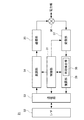
図1(a)は、本実施の形態による電力線搬送通信システム1のシステム構成を示す図である。同図に示すように、電力線搬送通信システム1は、親機C0と、それぞれ親機C0に接続する電力線B1〜B3とを備え、各電力線B1〜B3には、それぞれリピータ機能を内蔵する子機C11〜C37がバス接続されている。親機C0及び各子機C11〜C37はいずれも電力線搬送通信装置であり、相互に、上述したOFDM通信又は位相変調通信による電力線搬送通信を行う。そして、図示しない端末装置(パソコン、電気メータなど)と接続されて端末装置間での通信を実現する。
Fig.1 (a) is a figure which shows the system configuration | structure of the power line
電力線B1〜B3は親機C0の近辺に設けられた接続点N(例えば分電盤)で互いに接続されており、一の電力線に流れる信号は、他の電力線にも流れる。したがって、電力線B1〜B3に、同一周波数の信号を互いに独立して同時に流すことは原則としてできないが、接続点Nとの距離がある程度以上離れている子機が送信した信号は、接続点Nに到達する前に減衰してしまうため他の電力線に流れこむことはない。したがって、このような信号に限れば、電力線B1〜B3に、同一周波数の信号を互いに独立して同時に流すことが可能である。 The power lines B1 to B3 are connected to each other at a connection point N (for example, a distribution board) provided in the vicinity of the parent device C0, and a signal flowing through one power line also flows to another power line. Therefore, in principle, signals of the same frequency cannot be sent to power lines B1 to B3 independently of each other at the same time. However, a signal transmitted by a slave whose distance from connection point N is more than a certain distance is transmitted to connection point N. Since it attenuates before reaching, it does not flow into other power lines. Therefore, if it is limited to such a signal, it is possible to simultaneously flow signals of the same frequency to power lines B1 to B3 independently of each other.
この電力線搬送通信システム1は、具体的には、例えば図15に示した背景技術の例と同様、3階建てで各階に7つずつの部屋を有する集合住宅Aに設置され、各戸のメータ検針を行うために用いられる。以下の説明では、親機C0に接続される端末装置はパソコンであり、各子機に接続される端末装置は電気メータであるとし、パソコンから各電気メータの検針データの取得を行う例を取り上げる。なお、本発明が電気メータの検針データを取得する電力線搬送通信システムに限定されないのはもちろんである。
Specifically, the power line
ここで、親機C0及び各子機C11〜C37の詳細について説明するに先立ち、低周波数帯域を分割してなる第1及び第2の周波数帯について説明しておく。 Here, before describing the details of the parent device C0 and each of the child devices C11 to C37, the first and second frequency bands obtained by dividing the low frequency band will be described.
電力線搬送通信システム1では、OFDM通信を行う際、低周波数帯域(10kHz〜450kHz)を第1の周波数帯F1と第2の周波数帯F2に分割して用いる。すなわち、親機C0及び各子機C11〜C37は、いずれか一方の周波数帯に属するサブキャリアのみを用いて、OFDM信号(OFDM変調方式によって変調された搬送波信号)を生成する。
In the power line
図2は、第1及び第2の周波数帯の説明図である。同図に示すように、第1の周波数帯F1は10kHz〜220kHzの周波数帯域であり、第2の周波数帯F2は240kHz〜450kHzの周波数帯域である。低周波数帯域は10kHz〜450kHzであるので、第1の周波数帯F1は概ね低周波数帯域の下半分を占め、第2の周波数帯F2は概ね上半分を占めていることになる。 FIG. 2 is an explanatory diagram of the first and second frequency bands. As shown in the figure, the first frequency band F 1 is the frequency band of 10KHz~220kHz, frequency band F 2 of the second is the frequency band of 240KHz~450kHz. Since the low frequency band is 10 kHz to 450 kHz, the first frequency band F 1 generally occupies the lower half of the low frequency band, and the second frequency band F 2 generally occupies the upper half.
図3の各図は、OFDM信号の周波数スペクトラムイメージを示している。図3(a)は低周波数帯域全体を用いてOFDM通信を行う場合のOFDM信号の周波数スペクトラムイメージであり、同図に示すように、この場合のOFDM信号のサブキャリアは10kHz〜450kHzの低周波数帯域の全域にわたって存在する。図3(b)は第1の周波数帯F1のみを用いるOFDM通信(以下、第1のOFDM通信という。)を行う場合のOFDM信号の周波数スペクトラムイメージであり、同図に示すように、この場合のOFDM信号のサブキャリアは10kHz〜220kHzの範囲のみに存在する。図3(c)は第2の周波数帯F2のみを用いるOFDM通信(以下、第2のOFDM通信という。)を行う場合のOFDM信号の周波数スペクトラムイメージであり、同図に示すように、この場合のOFDM信号のサブキャリアは240kHz〜450kHzの範囲のみに存在する。図3(d)は第1のOFDM通信によるOFDM信号と第2のOFDM通信によるOFDM信号とが混在している状態を示しており、この場合のOFDM信号のサブキャリアは、220kHz〜240kHzの範囲を除き、低周波数帯域の全域にわたって存在する。 Each figure in FIG. 3 shows a frequency spectrum image of the OFDM signal. FIG. 3A is a frequency spectrum image of an OFDM signal when OFDM communication is performed using the entire low frequency band. As shown in FIG. 3, the subcarrier of the OFDM signal in this case is a low frequency of 10 kHz to 450 kHz. Exists across the entire band. FIG. 3B is a frequency spectrum image of an OFDM signal when performing OFDM communication using only the first frequency band F 1 (hereinafter referred to as first OFDM communication). As shown in FIG. In this case, the subcarrier of the OFDM signal exists only in the range of 10 kHz to 220 kHz. FIG. 3 (c) OFDM communication using only the second frequency band F 2 (hereinafter, second OFDM communication called.) Is the frequency spectrum image of the OFDM signal in the case of performing, as shown in the figure, the In this case, the subcarrier of the OFDM signal exists only in the range of 240 kHz to 450 kHz. FIG. 3D shows a state where OFDM signals by the first OFDM communication and OFDM signals by the second OFDM communication are mixed, and the subcarrier of the OFDM signal in this case is in the range of 220 kHz to 240 kHz. Except for the entire low frequency band.
ここで、以下の説明の前提を説明しておく。以下では、電力線搬送通信システム1内の各子機と親機C0との通信状態は、図4に示す通りであると仮定する。すなわち、図4に示すように、親機C0は、子機C11〜C14、C21〜C23、C31〜C32との間で、OFDM信号と位相変調信号(位相変調方式により変調された搬送波信号)の両方を送受信できる。また、子機C15〜C17、C24〜C26、C33〜C35との間では、OFDM信号は送受信できないが、位相変調信号の送受信はできる。その他の子機C27、C36〜C37との間では、OFDM信号・位相変調信号ともに送受信できないものとする。
Here, the premise of the following description is demonstrated. In the following, it is assumed that the communication state between each child device in the power line
図1(b)は、電力線搬送通信システム1のネットワークトポロジを示す図である。同図に示すように、本実施の形態では、同図に示すように、本実施の形態では、論理的に親機C0と直接接続しているのは子機C11〜C14,C21〜C23,C31〜C32(以下、直接通信子機と総称する。)のみである。このうち、子機C14,C23,C32はリピータ(以下、リピータ子機と総称する。)として用い、各電力線上で親機C0との距離がリピータ子機よりも離れている子機C15〜C17,C24〜C27,C33〜C37(以下、リピータ経由通信子機と総称する。)は、リピータとしての子機C14,C23,C32を介して、親機C0と接続されている。
FIG. 1B is a diagram showing a network topology of the power line
このようなネットワークトポロジを採用しているのは、図4に示したように、リピータ経由通信子機は、距離が離れ過ぎていて親機C0とOFDM通信による直接通信ができないためである。具体的に各子機を直接通信子機、リピータ経由通信子機のいずれとするか、またどの子機をリピータ子機として用いるかについては、親機C0の処理によってシステム立ち上げ時に自動決定される。この処理の詳細については、後にまとめて説明する。 The reason why such a network topology is adopted is that, as shown in FIG. 4, the repeater-directed communication slave unit is too far away to perform direct communication with the master unit C0 by OFDM communication. Specifically, whether each slave unit is a direct communication slave unit or a communication slave unit via a repeater, and which slave unit is used as a repeater slave unit is automatically determined at the time of system startup by the process of the master unit C0. The Details of this process will be described later.
さて、図5(a)は、親機C0の機能ブロックを示す図である。同図に示すように、親機C0は、それぞれ電力線に接続するモデム11及び同期信号生成器12と、制御部13と、バッファ14と、端末装置としてのパソコンに接続するインタフェース15とを有している。
FIG. 5A is a diagram showing functional blocks of the parent device C0. As shown in the figure, the base unit C0 has a
モデム11は、上記第2のOFDM通信を行うとともに、第1の周波数帯F1に属する周波数(具体的には115kHz又は132kHz)を用いて位相変調通信を行うモデムである。指示データ及び検針データの送受信にはOFDM通信を用い、リピータ子機への呼び出し信号の送信には位相変調通信を用いる。具体的には、制御部13の指示に従い、バッファ14に記憶されるデータ又はインタフェース15を介してパソコンから入力されるデータに基づいて第1の周波数帯F1の搬送波周波数で位相変調し、変調方式に応じた既知の同期信号を含む所定のプリアンブルを付加した上で電力線に送出する。また、モデム11が付加する同期信号は、搬送波信号の変調にOFDM変調方式を用いる場合には、搬送波信号と同じ周波数帯に属するサブキャリアのみによって構成される広帯域信号である。一方、搬送波信号の変調に位相変調方式を用いる場合には、搬送波信号と同じ周波数の単一周波数信号である。電力線を流れる第1の周波数帯F1の位相変調搬送波信号を受信して復調し、得られたデータを、制御部13の指示に従ってバッファ14又はインタフェース15に出力する。
The
なお、OFDM信号は各サブキャリアの出力の合計が100mWとなるように出力調整されて送出される。一方、位相変調信号は350mWの出力で送出される。このような出力としているのは、上掲の表1に示した法規制に従うためである。 It should be noted that the OFDM signal is transmitted with its output adjusted so that the total output of each subcarrier is 100 mW. On the other hand, the phase modulation signal is transmitted with an output of 350 mW. The reason for this output is to comply with the laws and regulations shown in Table 1 above.
他に、モデム11は、信号を送信する際、CSMA/CA(Carrier Sense Multiple Access/Collision Avoidance)方式を用いるよう構成されている。すなわち、モデム11は、送信を開始する前に一度受信を試み(キャリアセンス)、他の装置の送信信号が検知されなければ、送信データの送信を行う。他の装置の送信信号が検知された場合には、その送信信号の送信終了を監視し、送信終了が検知された場合に所定時間待機してから送信データの送信を行う。なお、この所定時間は待機回数の増加に応じて短くなるよう決定される。通信開始時のネゴシエーションは行われない。
In addition, the
同期信号生成器12は、電力線を流れる信号に既知の同期信号が含まれているか否かを監視する。含まれていることが検出された場合、その同期信号を用いて同期を確立し、同期を確立したことを示す情報を制御部13に通知する。この通知を受けた制御部13は、モデム11に復調処理を開始させる。
The
制御部13は、ここまでに挙げた処理の他、親機C0の各部を制御する処理を行う。また、制御部13は、パソコンからの指示に従って検針データの送信を指示するための指示データを生成し、モデム11を用いて各子機に向けて送信するとともに、指示データに応じて各子機から返送されてきた検針データをモデム11を介して受信する。
In addition to the processing described so far, the
なお、親機C0が指示データを送信する順序は、予めプログラミングされる。このプログラミングの詳細については後述する。また、制御部13は機能的に、判定部16(判定手段)、選択部17(選択手段)、切替部18(切替手段)を含んでいるが、これらの処理についても後述する。
The order in which the parent device C0 transmits the instruction data is programmed in advance. Details of this programming will be described later. The
バッファ14は、制御部13の指示に従い、モデム11から入力されるデータを記憶する記憶手段である。インタフェース15はパソコンとの間でデータの入出力を行う。
The
図5(b)は、子機C11〜C37の機能ブロックを示す図である。なお、本実施の形態では、いずれの子機も同様の機能ブロックを有している。図5(b)に示すように、子機C11〜C37は、それぞれ電力線に接続するモデム21及び同期信号生成器23と、制御部24と、バッファ25と、端末装置としての電気メータに接続するインタフェース26とを有している。
FIG. 5B is a diagram showing functional blocks of the slave units C11 to C37. In this embodiment, all the slave units have the same functional block. As shown in FIG.5 (b), the subunit | mobile_unit C11-C37 is connected to the
モデム21は、上記第1及び第2のOFDM通信を行うとともに、第1の周波数帯F1に属する周波数(具体的には115kHz又は132kHz)を用いて位相変調通信を行う機能を備えたモデムである。リピータ子機の場合、親機C0からの呼び出し信号の受信の際には位相変調通信を用い、リピータ子機配下の子機からの信号を受信する際には第1のOFDM通信を用いる。また、親機C0とリピータ子機もしくは直接通信子機の間で指示データ及び検針データを送受信する際には第2のOFDM通信を用い、リピータ子機と配下の子機との間で指示データ及び検針データを送受信する際には第1のOFDM通信を用いる。
The
モデム21の基本的な機能は、第1の周波数帯F1も用いる点を除き、上述したモデム11の機能と同様である。すなわち、モデム21は、制御部24の指示に従い、バッファ25に記憶されるデータ又はインタフェース26を介して図示しない端末装置から入力されるデータに基づいて第1の周波数帯F1又は第2の周波数帯F2の搬送波信号を変調し、変調方式に応じた既知の同期信号を含む所定のプリアンブルを付加した上で電力線に送出する。また、電力線を流れる第1の周波数帯F1又は第2の周波数帯F2の変調搬送波信号を受信して復調し、得られたデータを、制御部24の指示に従ってバッファ25又はインタフェース26に出力する。なお、信号の送信にはCSMA/CA方式を用いる。
The basic function of the
モデム21が付加する同期信号は、搬送波信号の変調にOFDM変調方式を用いる場合には、搬送波信号と同じ周波数帯に属するサブキャリアのみによって構成される広帯域信号である。一方、搬送波信号の変調に位相変調方式を用いる場合には、搬送波信号と同じ周波数の単一周波数信号である。
The synchronization signal added by the
モデム21について、より詳細に説明する。図6は、モデム21の機能ブロックを示す図である。同図に示すように、モデム21は、制御部31、インタフェース(I/F)32、通信部33、変調部34、送信部35、マルチプレクサ36、受信部37、復調部38の各機能部を有している。
The
制御部31は、制御部24から信号の送信先情報を含む各種の情報を取得し、取得した情報に基づいてモデム21の各部を制御する。
The
インタフェース32は、制御部24やバッファ25などの上位装置とのインタフェースであり、上位装置から上位レイヤデータを受け取り、通信部33に出力する。また、通信部33から上位レイヤデータの入力を受け、上位装置に出力する。通信部33はヘッダを含む送受信信号の処理を行う機能部であり、例えばDSP(Digital Signal Processor)によって構成される。具体的な処理としては、インタフェース32から送信すべき上位レイヤデータの供給を受け、パイロットデータや宛先MACアドレスなどを含むヘッダと誤り訂正のための冗長データとを付加し、送信データとして変調部34に送出する。また、復調部38からヘッダと上位レイヤデータとを含む受信データの入力を受け、その中のヘッダに応じた処理及び誤り訂正処理を行うとともに、上位レイヤデータのインタフェース32への出力を行う。
The
なお、ヘッダに応じた処理には、受信データに対する所定の応答データ(Acknowledge)を、上記送信データのひとつとして送信する処理が含まれる。すなわち、通信部33は、他の電力線搬送通信装置から信号を受信したら、その都度応答データを返送するよう構成されている。なお、応答データを含む信号を応答信号という。したがって、通信部33は、応答データ以外の送信データを送信したにも関わらず送信してから所定時間内に応答データを受信しない場合には、正常に受信されなかったものとして、送信データの再送を行う。
The process according to the header includes a process of transmitting predetermined response data (Acknowledge) to the received data as one of the transmission data. That is, the
変調部34は、制御部31の指示に従い、OFDM変調方式並びに位相変調方式の中から一の変調方式を選択する。そして、選択した一の変調方式を用い、送信データに基づいて搬送波信号を変調し、変調方式に応じた既知の同期信号を含む所定のプリアンブルを付加するとともに、表1に示した電波法施行規則の規定(搬送波出力)に則り変調処理に用いた通信方式に応じて信号の振幅を制御した後、送信部35に出力する。
The
ここで、制御部31は、送信信号の送信先及び内容に応じて、変調部34が用いる変調方式及び周波数(サブキャリア)を制御する。すなわち、リピータ子機で送信信号の送信先が親機C0であり、かつ送信信号が呼び出し信号又はその応答信号である場合には、115kHz又は132kHzの単一サブキャリアを用いて位相変調を行うよう変調部34を制御する。また、送信信号の送信先が親機C0であり、かつ送信信号が指示データや検針データを含む信号である場合には、第2の周波数帯F2に属するサブキャリアのみを用いてOFDM変調を行うよう変調部34を制御する。また、リピータ子機と配下の子機間では、送信信号の内容にかかわらず、第1の周波数帯F1に属するサブキャリアのみを用いてOFDM変調を行うよう変調部34を制御する。
Here, the
送信部35は、変調部34から入力された信号を電力線に送出可能な信号に変換してから、電力線に送出する機能を有する。具体的には、変調部34から入力されるデジタル信号をアナログ信号に変換するとともに、バンドパスフィルタを用いて不要な周波数帯成分を取り除き、さらに所定の増幅率で増幅して、マルチプレクサ36を介して電力線に送出する。
The
受信部37は、電力線に到来した信号を受信してデジタル信号に変換し、復調部38に出力する機能を有する。具体的には、マルチプレクサ36を介して受信された信号を所定の増幅率で増幅した後、サンプリングしてデジタル信号に変換し、復調部38に出力する。
The receiving
加えて、受信部37は、2つの通信モードを切り替えながら、復調部38への信号出力を行う機能を有する。2つの通信モードは、受信信号のうち第1の周波数帯F1以外の周波数の信号を遮断するF1モード、受信信号のうち第2の周波数帯F2以外の信号を遮断するF2モードの2つである。各通信モードのさらなる詳細については後述することにする。
In addition, the
復調部38は、受信部37から入力されるデジタル信号を、OFDM変調方式及び位相変調方式を用いて復調する機能を有する。復調部38は、復調によって得た信号を通信部33に出力する。復調部38の詳細についても後述することにする。
The
図5(b)に戻る。同期信号生成器23の機能は、上述した同期信号生成器12の機能と同様である。なお、同期信号生成器23から同期を確立したことを示す情報の通知を受けた制御部24は、モデム21に復調処理を開始させる。
Returning to FIG. The function of the
制御部24は、ここまでに挙げた処理の他、子機の各部を制御する処理を行う。また、制御部24は、親機C0又はリピータ子機から自機宛の上記指示データ(検針データを送信するよう指示するための指示データ)が受信された場合、インタフェース26を介して電気メータにアクセスして検針データを取得し、取得した検針データを、指示データを受信したモデムを用いて返送する。
The
さらに、制御部24は、自機を、親機C0と他の子機との間の通信を中継するリピータとして機能させるか否かを記憶している。リピータとして機能させる場合には、さらに配下の子機を示す情報も記憶しており、親機C0から配下の子機宛の上記指示データが受信された場合、宛先の子機に対して指示データを転送する。そして、この転送に応じて配下の子機から返送されてきた検針データを、親機C0に転送する。
Further, the
バッファ25は、制御部24の指示に従い、モデム21から入力されるデータを記憶する記憶手段である。インタフェース26は電気メータとの間でデータの入出力を行う。
The
次に、親機C0と子機C11〜C37の間で行われる指示データ及び検針データの送受信について、詳しく説明する。 Next, transmission / reception of instruction data and meter reading data performed between the parent device C0 and the child devices C11 to C37 will be described in detail.
図1(a)(b)に示すように、親機C0と各直接通信子機との通信には、第2の周波数帯F2を用いる。つまり、各直接通信子機は、第2のOFDM通信により、親機C0と指示データ及び検針データの送受信を行う。一方、リピータ子機とリピータ経由通信子機との通信には、第1の周波数帯F1を用いる。つまり、これらの子機は、第1のOFDM通信により、相互に指示データ及び検針データの送受信を行う。 As shown in FIG. 1 (a) (b), to communicate with the base unit C0 and the direct communication slave unit, a second using frequency band F 2. That is, each direct communication handset transmits / receives instruction data and meter reading data to / from the base unit C0 by the second OFDM communication. On the other hand, for communication with the repeater handset and the repeater via a communication slave unit, first using a frequency band F 1. That is, these slaves mutually transmit and receive instruction data and meter reading data by the first OFDM communication.
図7の各図は、親機C0と各子機との間若しくは子機間で送受信される信号のフォーマットを示す図である。なお、これらの図に示しているのはネットワークレイヤより上位のレイヤに係る部分のみであって、同期信号など、ネットワークレイヤより低いレイヤに係る部分については示していない。以下、これらの図を参照しながら、親機C0と各子機との間及び子機間での信号の送受信について説明する。 Each diagram in FIG. 7 is a diagram illustrating a format of a signal transmitted / received between the parent device C0 and each child device or between the child devices. Note that these drawings only show portions related to layers higher than the network layer, and do not show portions related to layers lower than the network layer, such as synchronization signals. Hereinafter, transmission and reception of signals between the parent device C0 and each child device and between child devices will be described with reference to these drawings.
まず、図7(a)は、親機C0が直接通信子機(リピータ子機を除く)に指示データを送信する際に用いる信号のフォーマットである。パソコンから検針データ取得の指示を受けた親機C0は、指示データと、宛先アドレスとしての直接通信子機のアドレスと、送信元としての自機のアドレスとを含む信号を生成し、第2のOFDM通信により電力線B1〜B3上に送出する。各子機は電力線上を流れる信号のヘッダを監視しており、自機のアドレスが付加された信号が流れてきた場合に、その信号を受信する。 First, FIG. 7A shows a signal format used when the parent device C0 transmits instruction data directly to a communication child device (excluding a repeater child device). Receiving the meter reading data acquisition instruction from the personal computer, the base unit C0 generates a signal including the instruction data, the address of the direct communication slave unit as the destination address, and the address of the own unit as the transmission source. It transmits on power line B1-B3 by OFDM communication. Each slave unit monitors the header of a signal flowing on the power line, and receives a signal when a signal to which the address of the slave unit is added flows.
図7(b)は、直接通信子機(リピータ子機を除く)が親機C0に検針データを送信する際に用いる信号のフォーマットである。図7(a)の信号を受信した各直接通信子機は、まず電気メータから検針データを取得する。そして、検針データと、宛先アドレスとしての親機C0のアドレスと、送信元としての自機のアドレスとを含む信号を生成し、第2のOFDM通信により電力線上に送出する。親機C0は電力線B1〜B3上を流れる信号のヘッダを監視しており、自機のアドレスが付加された信号が流れてきた場合に、その信号を受信する。以上の処理により、直接通信子機(リピータ子機を除く)からの検針データの取得が完了する。 FIG. 7B shows a signal format used when a direct communication slave unit (excluding a repeater slave unit) transmits meter-reading data to the master unit C0. Each direct communication slave that has received the signal of FIG. 7A first acquires meter reading data from an electric meter. And the signal containing meter-reading data, the address of the main | base station C0 as a destination address, and the address of the own machine as a transmission source is produced | generated, and it sends out on a power line by 2nd OFDM communication. The base unit C0 monitors the header of the signal flowing on the power lines B1 to B3, and receives the signal when the signal with its own address added flows. With the above processing, the acquisition of meter reading data from the direct communication slave unit (excluding the repeater slave unit) is completed.
次に、図7(c)は、親機C0がリピータ子機及びリピータ経由通信子機に指示データを送信する際に用いる信号のフォーマットである。親機C0は、指示データと、宛先アドレスとしてのリピータ子機のアドレスと、送信元としての自機のアドレスとを含む信号を生成し、第2のOFDM通信により電力線B1〜B3上に送出する。 Next, FIG. 7C shows a signal format used when the parent device C0 transmits instruction data to the repeater child device and the repeater child communication device. Base unit C0 generates a signal including the instruction data, the address of the repeater slave unit as the destination address, and the address of its own unit as the transmission source, and transmits the signal onto power lines B1 to B3 by the second OFDM communication. .
図7(d)は、リピータ子機が配下のリピータ経由通信子機に指示データを転送する際に用いる信号のフォーマットである。リピータ子機は、親機C0から受信した信号の宛先アドレス及び送信元アドレスを、それぞれリピータ経由通信子機のアドレス及び自機のアドレスで書き換え、第1のOFDM通信により電力線上に送出する。 FIG. 7D shows a signal format used when the repeater slave unit transfers instruction data to the subordinate repeater slave unit. The repeater slave unit rewrites the destination address and the transmission source address of the signal received from the master unit C0 with the address of the slave unit via the repeater and the address of the own unit, respectively, and sends it over the power line by the first OFDM communication.
図7(e)は、リピータ経由通信子機がリピータ子機に検針データを送信する際に用いる信号のフォーマットである。図7(d)の信号を受信した各リピータ経由通信子機は、まず電気メータから検針データを取得する。また、受信した信号の送信元アドレスから、検針データの宛先アドレス(すなわち、リピータ子機のアドレス)を取得する。そして、検針データと、宛先アドレスとしてのリピータ子機のアドレスと、送信元としての自機のアドレスとを含む信号を生成し、第1のOFDM通信により電力線上に送出する。 FIG. 7E shows a signal format used when the communication slave unit via repeater transmits meter reading data to the repeater slave unit. Each of the communication slave devices via repeaters that has received the signal of FIG. 7D first acquires meter reading data from an electric meter. Further, the destination address of meter reading data (that is, the address of the repeater slave unit) is acquired from the source address of the received signal. Then, a signal including the meter reading data, the address of the repeater slave as the destination address, and the address of the own device as the transmission source is generated, and is transmitted onto the power line by the first OFDM communication.
図7(f)は、リピータ子機が親機C0に検針データを送信する際に用いる信号のフォーマットである。図7(c)の信号を受信したリピータ子機は、自機に接続されている電気メータから検針データを取得し、バッファ25(図5(b))に蓄積する。また、図7(e)に示した信号により、配下のリピータ経由通信子機からも検針データを取得し、バッファ25(図5(b))に蓄積する。そして、リピータ子機は、すべての検針データの取得が完了したら、蓄積された検針データと、宛先アドレスとしての親機C0のアドレスと、送信元としての自機のアドレスとを含む信号を生成し、第2のOFDM通信により電力線上に送出する。親機C0は、この信号を受信することにより、リピータ子機及びリピータ経由通信子機からの検針データの取得を完了する。 FIG. 7F shows a signal format used when the repeater slave unit transmits meter reading data to the master unit C0. The repeater slave unit that has received the signal of FIG. 7C acquires meter reading data from the electric meter connected to the repeater unit and stores it in the buffer 25 (FIG. 5B). Also, meter reading data is acquired from the subordinate repeater communication slave unit by the signal shown in FIG. 7E, and stored in the buffer 25 (FIG. 5B). Then, when the repeater slave unit completes the acquisition of all the meter reading data, it generates a signal including the accumulated meter reading data, the address of the parent device C0 as the destination address, and the address of the own device as the transmission source. Then, it is transmitted on the power line by the second OFDM communication. By receiving this signal, the master unit C0 completes the acquisition of meter reading data from the repeater slave unit and the repeater slave unit.
以上、親機C0と各子機との間及び子機間で行われる信号の送受信について説明した。次に、この信号送受信の具体的な手順について説明する。 The transmission / reception of signals performed between the parent device C0 and each child device and between the child devices has been described above. Next, a specific procedure of this signal transmission / reception will be described.
図8は、親機C0と各子機との間及び子機間での通信ステップを示す模式図である。同図中の矢印は信号a〜fの送受信を示している。なお、信号a〜fは、図7(a)〜(f)に対応している。また、以下の説明で親機C0が信号を送信する順序は、子機の数などを考慮して、総通信ステップ数が最も少なくなるように予めプログラミングされたものである。 FIG. 8 is a schematic diagram showing communication steps between the parent device C0 and each child device and between child devices. Arrows in the figure indicate transmission and reception of signals a to f. Signals a to f correspond to FIGS. 7 (a) to 7 (f). In the following description, the order in which the base unit C0 transmits signals is programmed in advance so that the total number of communication steps is minimized in consideration of the number of slave units.
まず初めに、信号の同時送受信について説明しておく。信号a〜c,fの送受信には第2のOFDM通信が用いられ、信号d,eの送受信には第1のOFDM通信が用いられることから、信号a〜c,fと信号d,eとは、電力線B1〜B3上で同時に送受信することができる。また、各リピータ子機及びその配下のリピータ経由通信子機の間で送受信される信号は、機器間の距離が十分に離れているため、他のリピータ子機及びその配下のリピータ経由通信子機の間で送受信される信号とは干渉しない。したがって、各リピータ子機及びその配下のリピータ経由通信子機の間での信号の送受信は、各電力線上で互いに独立して同時に行うことが可能である。親機C0における上記プログラミングは、これらを考慮して行われる。 First, simultaneous transmission / reception of signals will be described. Since the second OFDM communication is used for transmitting and receiving the signals a to c and f, and the first OFDM communication is used for transmitting and receiving the signals d and e, the signals a to c and f and the signals d and e Can simultaneously transmit and receive on the power lines B1 to B3. In addition, the signals transmitted and received between each repeater slave unit and its subordinate repeater slave units are sufficiently separated from each other, so that other repeater slave units and its subordinate repeater slave units are also separated. Does not interfere with signals transmitted and received between the two. Therefore, transmission / reception of signals between each repeater slave unit and a repeater-directed communication slave unit under the repeater slave unit can be performed simultaneously and independently on each power line. The above programming in the parent device C0 is performed in consideration of these.
さて、図8に示すように、親機C0は、まず3つのリピータ子機C32,C23,C14を順次宛先として、信号c(指示データを含む信号)を送信する(ステップ1〜3)。この送信は第2のOFDM通信により行われる。
As shown in FIG. 8, base unit C0 first transmits signal c (signal including instruction data) with three repeater slave units C32, C23, and C14 as destinations in sequence (
各リピータ子機C32,C23,C14は、親機C0から信号cを受信すると直ちに、配下のリピータ経由通信子機のうちのひとつを宛先として、信号d(指示データを含む信号)を第1のOFDM通信により送信する(ステップ2〜4)。信号dを受信したリピータ経由通信子機は直ちに検針データを取得し、リピータ子機に向けて信号e(検針データを含む信号)を第1のOFDM通信により返送する(ステップ3〜5)。各リピータ子機C32,C23,C14は、こうして受信した信号eに含まれる検針データをバッファ25に蓄積する。各リピータ子機C32,C23,C14は、以上の処理を配下のリピータ経由通信子機すべてについて繰り返す(リピータ子機C32についてはステップ2〜11。リピータ子機C23についてはステップ3〜10。リピータ子機C14についてはステップ4〜9。)。そして、すべての配下のリピータ経由通信子機の検針データが蓄積されたら、自機の検針データも含む信号fを生成し、親機C0に向けて第2のOFDM通信により送信する(ステップ10〜12)。
As soon as each of the repeater slaves C32, C23, C14 receives the signal c from the master device C0, each repeater slave C32, C23, C14 receives a signal d (a signal including instruction data) as a first address with one of the subordinate repeater communication slaves as the destination Transmission is performed by OFDM communication (
本実施の形態では各リピータ子機C32,C23,C14の配下にそれぞれ5つ,4つ,3つのリピータ経由通信子機があるので、親機C0がリピータ子機C14に向けて信号cを送信したステップ3の7ステップ後であるステップ10で、まずリピータ子機C14が信号fを親機C0に向けて第2のOFDM通信により送信する。次に、ステップ11,12で、リピータ子機C23,C32が順次、信号fを親機C0に向けて第2のOFDM通信により送信する。
In the present embodiment, since there are five, four, and three repeater-connected communication slave units under each of the repeater slave units C32, C23, and C14, the master unit C0 transmits the signal c to the repeater slave unit C14. In
ステップ4〜9でリピータ子機が上記処理を行っている間、親機C0は直接通信子機C11〜C13との間で第2のOFDM通信により信号a,bの送受信を行い、これらの子機から検針データを取得する。また、親機C0は、ステップ13以降で、残りの直接通信子機C21,C22,C31との間で第2のOFDM通信により信号a,bの送受信を行い、これらの子機から検針データを取得する。最終的に、ステップ18が完了した時点で、すべての子機からの検針データの取得が完了する。
While the repeater slave unit performs the above processing in
以上説明したように、電力線搬送通信システム1では、第1及び第2の周波数帯という重複しない2つの周波数帯を用いているので、リピータ子機がリピータ経由通信子機とOFDM通信している間、親機は他の子機とOFDM通信することができる。したがって、図17に示した背景技術に比べ、総通信ステップ数が低減される。
As described above, since the power line
ここから、リピータ子機が1つのOFDMモデムにより第1及び第2のOFDM通信の両方を行えるようにするとともに、リピータ子機の呼び出し信号の復調精度を向上させるための具体的な構成について説明する。 From here, a specific configuration for allowing the repeater slave unit to perform both the first and second OFDM communications by one OFDM modem and improving the demodulation accuracy of the call signal of the repeater slave unit will be described. .
まず、モデム21内の復調部38の内部構成について説明する。
First, the internal configuration of the
図9は、復調部38の内部構成を示す図である。同図に示すように、復調部38の機能は同期検出部39と復調処理部40とに分けられ、同期検出部39は、第1の周波数帯F1のOFDM信号に対応するF1同期検出部70、第2の周波数帯F2のOFDM信号に対応するF2同期検出部71、115kHzの位相変調信号に対応する115kHz同期検出部72、及び132kHzの位相変調信号に対応する132kHz同期検出部73を有して構成される。
FIG. 9 is a diagram illustrating an internal configuration of the
また、復調処理部40は、F1同期検出部70に直列接続されたスイッチ80及びF1復調処理部81(第1OFDM信号復調部)と、F2同期検出部71に直列接続されたスイッチ82及びF2復調処理部83(第2OFDM信号復調部)と、115kHz同期検出部72に直列接続されたスイッチ84及び115kHz復調処理部85(位相変調信号復調部)と、132kHz同期検出部73に直列接続されたスイッチ86及び132kHz復調処理部87(位相変調信号復調部)とを有して構成される。なお、F1復調処理部81は第1の周波数帯F1のOFDM信号を復調する機能を有し、F2復調処理部83は第2の周波数帯F2のOFDM信号を復調する機能を有し、115kHz復調処理部85は115kHzの位相変調信号を復調する機能を有し、132kHz復調処理部87は132kHzの位相変調信号を復調する機能を有する。
The
同期検出部39内の各同期検出部は、それぞれ対応する信号用の同期パターンを保持している。各同期検出部は、受信部37から入力される受信信号と、保持している同期パターンとの相関値を常時算出しており、算出された相関値が所定値を上回った場合に、対応する信号との同期を検出し、同期確立処理を行う。
Each synchronization detection unit in the
制御部31は、いずれかの同期検出部で同期が検出されると、そのことに応じて、同期を検出した同期検出部に接続されているスイッチをオンとし、対応する復調部に復調を開始させる。つまり、F1同期検出部70が同期を検出した場合には、スイッチ80をオンとし、F1復調処理部81にOFDM変調方式による復調を開始させる。また、F2同期検出部71が同期を検出した場合には、スイッチ82をオンとし、F2復調処理部83にOFDM変調方式による復調を開始させる。また、115kHz同期検出部72が同期を検出した場合には、スイッチ84をオンとし、115kHz復調処理部85に位相変調方式による復調を開始させる。また、132kHz同期検出部73が同期を検出した場合には、スイッチ86をオンとし、132kHz復調処理部87に位相変調方式による復調を開始させる。
When synchronization is detected by any of the synchronization detection units, the
復調処理部40内の各復調処理部は、復調によって得られた信号を通信部33に出力する。
Each demodulation processing unit in the
次に、受信部37について説明する。上述したように、受信部37は、F1モード及びF2モードという2つの通信モードを有している。電力線搬送通信システム1内の各子機では、これらの通信モードを切り替えることにより、第1及び第2の周波数帯F1,F2のうちの一方の周波数帯を用いて通信を行う際、干渉ノイズとなる他方の周波数帯を遮断している。以下では、初めに受信部37の内部構成について説明し、その後、制御部31による通信モード実現のための制御について説明する。
Next, the receiving
図10は、受信部37の内部構成を示す図である。同図に示すように、受信部37は第1及び第2の信号通路41,42、ローノイズアンプ(LNA)49、自動ゲイン制御部(AGC)50とを有している。なお、同図ではアナログ信号をデジタル信号に変換するための変換部は省略している。
FIG. 10 is a diagram illustrating an internal configuration of the receiving
第1の信号通路41は、電力線と復調部38との間に設置され、第1の周波数帯F1以外の周波数の信号を遮断する機能部である。具体的には、マルチプレクサ36より入力された信号から、第1の周波数帯F1に属する周波数成分のみを取り出して通過させるバンドパスフィルタ45を有している。また、第1の信号通路41には、第1のスイッチ手段44が設けられている。第1のスイッチ手段44は、制御部31の制御によって開閉する。
The
第2の信号通路42は、電力線と復調部38との間に設置され、第2の周波数帯F2以外の周波数の信号を遮断する機能部である。具体的には、マルチプレクサ36より入力された信号から、第2の周波数帯F2に属する周波数成分のみを取り出して通過させるバンドパスフィルタ47を有している。また、第2の信号通路42には、第2のスイッチ手段46が設けられている。第2のスイッチ手段46も、制御部31の制御によって開閉する。
The
ローノイズアンプ49は、第1及び第2の信号通路41,42から出力された信号を所定の増幅率で増幅し、自動ゲイン制御部50に出力する。自動ゲイン制御部50は増幅回路を内蔵しており、復調部38からのフィードバック信号に基づいて、復調部38に入力される信号の振幅が一定値となるよう、増幅回路の増幅率を制御する。
The
さて、制御部31による受信部37の通信モード制御について説明する。制御部31は、下記の表2に従って、第1及び第2のスイッチ手段44,46を制御することにより、F1モード、F2モードという2つの通信モードを実現する。
リピータ子機が呼び出し信号を待ち受ける場合、制御部31は、第1のスイッチ手段44をオン、第2のスイッチ手段46をオフとすることで、受信部37の通信モードをF1モードとする。F1モードでは第1の周波数帯F1に属する周波数成分のみが復調部38に入力されることになるので、第1の周波数帯F1の呼び出し信号はもちろん、115kHz又は132kHzの位相変調信号である呼び出し信号も好適に受信できるようになる。
If the repeater slave unit waits for the call signal, the
リピータ子機や直接通信子機が親機C0との間で指示データや検針データの送受信を行う場合には、制御部31は、第1のスイッチ手段44をオフ、第2のスイッチ手段46をオンとすることで、受信部37の通信モードをF2モードとする。F2モードでは第2の周波数帯F2に属する周波数成分のみが復調部38に入力されることになるので、第2のOFDM通信による親機C0との通信を好適に行えることになる。
When the repeater slave unit or the direct communication slave unit transmits / receives instruction data or meter-reading data to / from the master unit C0, the
リピータ子機とリピータ配下子機との間で指示データや検針データの送受信を行う場合には、制御部31は、第1のスイッチ手段44をオン、第2のスイッチ手段46をオフとすることで、受信部37の通信モードをF1モードとする。F1モードでは第1の周波数帯F1に属する周波数成分のみが復調部38に入力されることになるので、第1のOFDM通信による他の子機との通信を好適に行えることになる。
When transmitting / receiving instruction data and meter reading data between the repeater slave unit and the repeater subordinate slave unit, the
次に、親機C0、子機C21(直接通信子機)、子機C32(リピータ子機)、子機C37(リピータ経由通信子機)の間で行われる通信のシーケンスを例として参照しながら、制御部31の処理についてさらに詳しく説明する。
Next, referring to the sequence of communication performed between the parent device C0, the child device C21 (direct communication child device), the child device C32 (repeater child device), and the child device C37 (communication child device via repeater) as an example. The processing of the
図11(a)は、上記シーケンスを示す図である。同図は、親機C0が子機C21及びC37から検針データを取得する場合のシーケンスを示している。なお、同図には、ネットワークレイヤより下位のレイヤのシーケンスを表示している。したがって、図8とは異なり、上述した応答信号(図11では「ACK」と表記している。)についても図の中に現れている。 FIG. 11A shows the above sequence. The figure shows a sequence in which the parent device C0 acquires meter-reading data from the child devices C21 and C37. In the figure, sequences of layers below the network layer are displayed. Therefore, unlike FIG. 8, the above-described response signal (indicated as “ACK” in FIG. 11) also appears in the figure.
図11(b)は、図11(a)に示す各信号の周波数帯と、リピータ子機C32の受信部37の通信モード設定(同図では「リピータ設定」と記す。)を示している。図11(b)の横軸は時間軸である。
FIG. 11B shows the frequency band of each signal shown in FIG. 11A and the communication mode setting of the receiving
初めに、図11(a)に示したシーケンスについて説明する。同図に示すように、親機C0は、リピータに対して呼び出し信号を送信する(ステップS1)。呼び出し信号を受信した子機C32は、親機C0に対してACKを送信する(ステップS2)。 First, the sequence shown in FIG. 11A will be described. As shown in the figure, base unit C0 transmits a calling signal to the repeater (step S1). The child device C32 that has received the call signal transmits ACK to the parent device C0 (step S2).
親機C0は、ACKを受信したら、子機C37のデータを要求するための信号c(図7)を子機C32に対して送信する(ステップS3)。子機C32は、この信号cについても、親機C0に対するACKの送信を行う(ステップS4)。子機C32は、受信した信号cに基づいて信号dを生成し、子機C37に送信する(ステップS5)。子機C37は検針データを含む信号eを返信し(ステップS6)、子機C32は受信した信号eに基づいて信号fを生成して親機C0に送信する(ステップS7)。親機C0は、信号fを受信したら、子機C32に対してACKを送信する(ステップS8)。 When receiving the ACK, the parent device C0 transmits a signal c (FIG. 7) for requesting the data of the child device C37 to the child device C32 (step S3). The slave unit C32 also transmits an ACK to the master unit C0 for this signal c (step S4). The subunit | mobile_unit C32 produces | generates the signal d based on the received signal c, and transmits to the subunit | mobile_unit C37 (step S5). The slave unit C37 returns a signal e including meter reading data (step S6), and the slave unit C32 generates a signal f based on the received signal e and transmits it to the master unit C0 (step S7). When receiving the signal f, the parent device C0 transmits ACK to the child device C32 (step S8).
次に、図11(b)を参照して、リピータ子機C32の受信部37の通信モード設定について説明する。同図に示すように、ステップS2でACKの送信を行うまでの間、リピータ子機C32の制御部31は受信部37をF1モードに設定する。これは、親機C0及び他の子機の両方からの呼び出しを待機するためである。一方、ステップS2でACKの送信を行った後には、制御部31は受信部37をF2モードに設定し、第2の周波数帯F2を用いる第2のOFDM通信によりステップS3〜S4の通信を行う。ステップS5で信号dの送信を行う際には、制御部31は受信部37をF1モードに設定し、第1の周波数帯F1を用いる第1のOFDM通信によりステップS5〜S6の通信を行う。そして、ステップS7の信号fの送信を行う際には、制御部31は受信部37をF2モードに戻し、第2の周波数帯F2を用いる第2のOFDM通信によりステップS7〜S8の通信を行う。ステップS8のACKの受信が完了したら、制御部31は受信部37をF1モードに戻し、呼び出し信号の待機を再開する。
Next, with reference to FIG.11 (b), the communication mode setting of the receiving
なお、図11(a)(b)にも示しているように、子機C32と子機C37とが通信を行っている間、親機C0は、第2の周波数帯F2を用いる第1のOFDM通信により、子機C21から検針データの取得を行う(ステップS9〜S10)。このように、リピータ子機がリピータ経由通信子機と通信している間、親機C0が直接通信子機と通信を行うのは、上述したように総通信ステップ数を低減するためである。
Incidentally, as shown in FIG. 11 (a) (b), while the the handset C32 and the slave device C37 are communicating, the master unit C0 is the use of the
以上説明したように、電力線搬送通信システム1によれば、リピータ子機は、受信部37と復調部38とにより構成されるOFDMモデムが1つだけであっても、第1の周波数帯F1の信号を用いる待ち受け時及び配下の子機とのOFDM通信と、第2の周波数帯F2の信号を用いる親機とのOFDM通信との両方を行える。
As described above, according to the power line
また、親機C0は位相変調通信により呼び出し信号を送信するので、表1に示すように350mWの高出力で呼び出し信号を送信することが可能になる。また、リピータ子機は第1の周波数帯F1のみで呼び出し信号を待ち受ければよくなるので、干渉ノイズとなる第2の周波数帯F2で信号を待ち受ける必要がなくなる。以上により、リピータ子機の呼び出し信号の復調精度が向上する。 Further, since base unit C0 transmits a call signal by phase modulation communication, it is possible to transmit the call signal with a high output of 350 mW as shown in Table 1. Further, since the repeater slave unit only has to wait for a call signal in the first frequency band F1, it is not necessary to wait for a signal in the second frequency band F2 that causes interference noise. As a result, the demodulation accuracy of the call signal of the repeater slave unit is improved.
また、電力線搬送通信システム1によれば、呼び出し信号を第1の周波数帯F1のOFDM信号及び第1の周波数帯F1に属する周波数の位相変調信号のいずれでも生成することが可能になる。したがって、親機C0及び配下の子機からリピータ子機に対する呼び出し信号を第1の周波数帯の信号に統一することが可能になる。つまり、親機C0は第1の周波数帯F1に属する周波数の位相変調信号により呼び出し信号を送信し、他の子機は第1の周波数帯F1のOFDM信号により呼び出し信号を送信することが可能になり、第1の周波数帯F1の信号のみが復調部に入力されるので、干渉ノイズが低減され、呼び出し信号の復調精度が向上する。
Further, according to the power
最後に、各子機を直接通信子機、リピータ経由通信子機のいずれとするか、またどの子機をリピータ子機として用いるかを決定するための親機の処理について説明しておくことにする。以下では、図1に示した電力線搬送通信システム1を前提として説明する。なお、この処理は電力線搬送通信システム1の立ち上げ時に行うことが好適である。また、初期状態では、親機C0には、子機C11〜C37のアドレス情報が事前に設定される。また、各子機の受信部37内の第1及び第2のスイッチ手段44,46はともにオンとなっている。すなわち、各子機は、第1及び第2の周波数帯F1,F2のいずれをも受信可能となっている。
Finally, the processing of the master unit for determining whether each slave unit is a direct communication slave unit or a repeater slave unit and which slave unit is used as a repeater slave unit will be described. To do. Below, it demonstrates on the assumption of the power line
図5(a)に示したように、親機C0は、判定部16、選択部17、切替部18を含んでいる。このうち、まず判定部16が、OFDM通信により直接通信できるか否かを子機ごとに判定する。次に、選択部17は、判定部16がOFDM通信により直接通信できると判定した子機の中から、リピータとして機能させる子機を選択し、選択した子機をリピータ子機として記憶する。そして、切替部18は、判定部16がOFDM通信により直接通信できないと判定した子機との通信を、リピータ子機を介する通信に切り替える。すなわち、これらの子機をリピータ経由通信子機として記憶するとともに、リピータ子機に対してリピータとして機能するよう命令する。この命令を受けたリピータ子機は、配下のリピータ経由通信子機との通信を第1のOFDM通信に切り替える。
As shown in FIG. 5A, the parent device C0 includes a
以下、親機C0の具体的な処理手順について詳しく説明する。 Hereinafter, a specific processing procedure of base unit C0 will be described in detail.
図12は、電力線B2に接続している各子機C21〜C27に関する処理の手順を示している。以下、この図12を参照しながら親機C0の処理について詳しく説明していくが、電力線B1,B3に接続している各子機に関しても、同様な手順で処理が行われる。 FIG. 12 shows a processing procedure regarding each of the slave units C21 to C27 connected to the power line B2. Hereinafter, the processing of the parent device C0 will be described in detail with reference to FIG. 12, but the processing is performed in the same procedure for each of the child devices connected to the power lines B1 and B3.
図12に示すように、まず判定部16が、子機C21に向けて通信品質確認用の信号gをユニキャスト送信する(ステップ1)。
As shown in FIG. 12, first, the
図13は、上記信号gのフォーマットを示す図である。同図に示すように、通信品質確認用の信号gは、第2のOFDM通信により伝送される部分、115kHzの位相変調通信により伝送される部分、132kHzの位相変調通信により伝送される部分の3つの部分信号から構成されている。各部分信号は、それぞれプリアンブルとユニキャストデータとを含んで構成され、それぞれ対応する変調方式により搬送波信号を変調するために用いられる。なお、プリアンブルには宛先の子機のアドレスが含まれ、ユニキャストデータには当該信号が通信品質確認用の信号であることを示す所定のデータが含まれる。 FIG. 13 shows the format of the signal g. As shown in the figure, the signal g for communication quality confirmation includes three parts: a part transmitted by the second OFDM communication, a part transmitted by the 115 kHz phase modulation communication, and a part transmitted by the 132 kHz phase modulation communication. It consists of two partial signals. Each partial signal includes a preamble and unicast data, and is used to modulate a carrier signal by a corresponding modulation scheme. The preamble includes the address of the destination slave unit, and the unicast data includes predetermined data indicating that the signal is a communication quality confirmation signal.
親機C0は、信号gの上記各部分信号を、順次電力線B1〜B3に送出する。図14は、こうして送出される信号gの周波数の時間変化を示す図である。同図に示すように、信号gの送出を周波数の時間変化で見ると、第2の周波数帯F2全体に広がる広帯域信号がまず送出され、続いて115kHzのみを用いる単一周波数信号が送出され、最後に132kHzのみを用いる単一周波数信号が送出されることになる。 Base unit C0 sequentially sends the partial signals of signal g to power lines B1 to B3. FIG. 14 is a diagram showing the time change of the frequency of the signal g transmitted in this way. As shown in the figure, when the transmission of the signal g is seen by the time change of the frequency, a wideband signal extending over the entire second frequency band F2 is transmitted first, followed by a single frequency signal using only 115 kHz. Finally, a single frequency signal using only 132 kHz will be transmitted.
図12に戻る。子機C21は、信号gの少なくとも一部が受信されると、部分信号ごとに、その受信品質を測定する。なお、受信品質には、受信レベル、信号対ノイズ比(SNR)、ビットエラー数、フレームエラー数などが含まれる。 Returning to FIG. The subunit | mobile_unit C21 will measure the reception quality for every partial signal, if at least one part of the signal g is received. The reception quality includes a reception level, a signal-to-noise ratio (SNR), the number of bit errors, the number of frame errors, and the like.
子機C21は、図4に示したように、親機C0との間でOFDM信号と位相変調信号の両方を送受信できる。したがって、子機C21は、信号gの3つの部分信号すべてを受信し、全部分信号が受信されたことを示す情報と、各部分信号の受信品質を示す情報を含む信号hを生成し、親機C0に向けて第2のOFDM通信により送信する(ステップ2)。 The subunit | mobile_unit C21 can transmit / receive both an OFDM signal and a phase modulation signal between the main | base stations C0, as shown in FIG. Accordingly, the slave unit C21 receives all three partial signals of the signal g, generates a signal h including information indicating that all the partial signals have been received and information indicating the reception quality of each partial signal. Transmit to the machine C0 by the second OFDM communication (step 2).
次に、判定部16は、子機C22に向けて通信品質確認用の信号gを送信する(ステップ3)。子機C22も、子機C21と同様に信号hを生成し、親機C0に向けて第2のOFDM通信により送信する(ステップ4)。子機C23についても同様である(ステップ5〜6)。
Next, the
次に、判定部16は、子機C24に向けて通信品質確認用の信号gを送信する(ステップ7)。子機C21は、図4に示したように、親機C0との間で位相変調信号のみを送受信でき、OFDM信号は送受信できない。したがって、子機C24は、信号gの3つの部分信号のうち位相変調通信により伝送される部分信号のみを受信し、位相変調通信により伝送される部分信号のみが受信されたことを示す情報と、これらの部分信号の受信品質を示す情報を含む信号h'を生成し、親機C0に向けて位相変調通信により送信する(ステップ8)。子機C25〜C26についても同様である(ステップ9〜12)。
Next, the
次に、判定部16は、子機C27に向けて通信品質確認用の信号gを送信する(ステップ13)。子機C27は、図4に示したように、親機C0との間でOFDM信号・位相変調信号のいずれも送受信できない。したがって、子機C27は信号gを受信できず、親機C0に向けて何も送信しない(ステップ14)。判定部16は、所定のタイミングで子機C27からの信号が受信されないことにより、OFDM通信では子機C27との直接通信ができないと判定する。
Next, the
以上の処理により、判定部16は、子機C21〜C23をOFDM通信により直接通信できる子機であると判定し、子機C24〜C27をOFDM通信では直接通信できない子機であると判定する。
Through the above processing, the
以上説明した判定部16の処理が完了し、OFDM通信で直接通信できない子機が1つでも存在していた場合、次に選択部17が、まずリピータ子機候補を選択する。具体的には、判定部16によりOFDM通信により直接通信できると判定された子機C21〜C23の中から、通信品質の低い順に所定個の子機をリピータ子機候補として選択する。通信品質の低い順とするのは、親機C0との通信品質が低いほど、直接通信できない子機に近いと考えられるからである。ここでは、所定個を2個とすることにすると、子機C22,C23がリピータ子機候補として選択される。
When the processing of the
選択部17は、選択したリピータ子機候補のうちのひとつである子機C22に対して、子機C24〜C27の存在確認を行うよう命令するための命令信号iを送信する(ステップ15)。子機C22の制御部24(図5(b))は、この命令信号iを受信すると、上述した判定部16の処理と同様に、子機C24〜C27に向けて通信品質確認用の信号gを順次第1のOFDM通信により送信し、各子機からの応答信号(信号h又は信号h')をバッファ25に蓄積する(ステップ16〜23)。そして、すべての子機に対する処理が完了したら、バッファ25に蓄積した各応答信号を含む信号jを生成し、親機C0に向けて第2のOFDM通信により送信する(ステップ24)。
The
選択部17は、選択したリピータ子機候補のうちの他のひとつである子機C23に対しても、子機C22と同様に、子機C24〜C27の存在確認を行わせる(ステップ25〜34)。
The
選択部17は、各リピータ子機候補C22,C23から受信した信号jに基づき、どちらの子機が、子機C24〜C27との通信状態がより良好であるかを判定する。そして、より良好であると判定した子機を、リピータ子機として選択する。なお、図1の例では、子機C23の方が子機C24〜C27との距離が近いので、子機C23がリピータ子機として選択される。
Based on signal j received from each repeater child device candidate C22, C23,
選択部17がリピータ子機を選択したら、次に切替部18が、リピータ子機C23に対して、リピータとして機能するよう命令するための命令信号kを第2のOFDM通信により送信する(ステップ35)。この命令信号kには、配下のリピータ経由通信子機となる子機C24〜C27を示す情報が含まれる。
When the
リピータ子機C23の制御部24(図5(b))は、この命令信号kを受信すると、自機がリピータ子機となることを記憶し、リピータとしての動作を開始するとともに、配下のリピータ経由通信子機C24〜C27に対して、次からは第1のOFDM通信により通信を行うよう命令するための命令信号lを送信する。各リピータ経由通信子機C24〜C27の制御部24は、この命令信号lを受信すると、受信部37をF1モードとして子機C23からの信号の待機を開始するとともに、所定の応答信号mをリピータ子機C23に対して第1のOFDM通信により返送する(ステップ36〜43)。
When receiving the command signal k, the control unit 24 (FIG. 5B) of the repeater child device C23 stores that the own device becomes a repeater child device, starts an operation as a repeater, and operates a subordinate repeater. Next, a command signal l for instructing to perform communication by the first OFDM communication is transmitted to the relay communication slave devices C24 to C27.
リピータ子機C23は、子機C24〜C27のすべてについて応答信号mの受信を完了すると、親機C0に対してネットワーク構築完了通知のための信号nを第2のOFDM通信により送信する(ステップ44)。親機C0は、この信号nを受信することにより子機C23がリピータとして機能し始めたことを認識し、子機C23をリピータとして用いる運用モードを開始する。具体的には、検針データの取得の際、子機C24〜C27には指示データを送らないこととし、子機C24〜C27の検針データはリピータ子機C23から受信する。なお、子機C23は、信号nを送信した後、受信部37をF1モードとして待ち受け状態に入る。
When the repeater slave C23 completes the reception of the response signal m for all of the slaves C24 to C27, the repeater slave C23 transmits a signal n for network construction completion notification to the master C0 by the second OFDM communication (step 44). ). Receiving this signal n, the parent device C0 recognizes that the child device C23 has started to function as a repeater, and starts an operation mode in which the child device C23 is used as a repeater. Specifically, when acquiring meter reading data, instruction data is not sent to the slave units C24 to C27, and the meter reading data of the slave units C24 to C27 is received from the repeater slave unit C23. Incidentally, the slave unit C23, after transmitting the signal n, enters a standby state of
以上説明したように、電力線搬送通信システム1によれば、リピータ子機を介して通信を行うリピータ経由通信子機と直接通信する直接通信子機とを、システム構築後に人手を介さずに分類することが可能になる。また、親機C0は、リピータ子機を適切に選択できる。
As described above, according to the power line
以上、本発明の好ましい実施の形態について説明したが、本発明はこうした実施の形態に何等限定されるものではなく、本発明が、その要旨を逸脱しない範囲において、種々なる態様で実施され得ることは勿論である。 As mentioned above, although preferable embodiment of this invention was described, this invention is not limited to such embodiment at all, and this invention can be implemented in various aspects in the range which does not deviate from the summary. Of course.
1 電力線搬送通信システム
11,21 モデム
12,23 同期信号生成器
13,24,31 制御部
14,25 バッファ
15,26,32 インタフェース
16 判定部
17 選択部
18 切替部
33 通信部
34 変調部
35 送信部
36 マルチプレクサ
37 受信部
38 復調部
39 同期検出部
40 復調処理部
41 第1の信号通路
42 第2の信号通路
44 第1のスイッチ手段
45,47 バンドパスフィルタ
46 第2のスイッチ手段
49 ローノイズアンプ
50 自動ゲイン制御部
70 F1同期検出部
71 F2同期検出部
72 115kHz同期検出部
73 132kHz同期検出部
80,82,84,86 スイッチ
81 F1復調処理部
83 F2復調処理部
85 115kHz復調処理部
87 132kHz復調処理部
B1〜B3 電力線
C0 親機
C11〜C17,C21〜C27,C31〜C37 子機
DESCRIPTION OF
Claims (3)
前記電力線に流れる信号を受信する受信部と、
前記受信部の受信信号を復調する復調部と、
制御部とを備え、
前記受信部は、
前記電力線と前記復調部との間に設置され、第1の周波数帯以外の周波数の信号を遮断する第1の信号通路と、
前記電力線と前記復調部との間に設置され、前記第1の周波数帯とは重複しない第2の周波数帯以外の周波数の信号を遮断する第2の信号通路と、
前記第1の信号通路に設けられた第1のスイッチ手段と、
前記第2の信号通路に設けられた第2のスイッチ手段とを有し、
前記制御部は、リピータ子機動作時には待ち受け時及び他の子機との通信を行う場合には前記第1のスイッチ手段をオン、前記第2のスイッチ手段をオフとし、前記親機との通信を行う場合には前記第1のスイッチ手段をオフ、前記第2のスイッチ手段をオンとすると共に、
前記復調部は、
前記第1の周波数帯のOFDM信号を復調する第1OFDM信号復調処理部と、
前記第2の周波数帯のOFDM信号を復調する第2OFDM信号復調処理部と、
前記第1の周波数帯に属する周波数の位相変調信号を復調する位相変調信号復調処理部とを有し、
前記位相変調信号復調処理部を用いて、呼び出し信号の復調を行うことを特徴とする電力線搬送通信装置。 A power line carrier communication device functioning as one of the slave units connected by bus to the power line connected to the master unit,
A receiver for receiving a signal flowing in the power line;
A demodulator that demodulates the received signal of the receiver;
A control unit,
The receiver is
A first signal path that is installed between the power line and the demodulator and blocks a signal having a frequency other than the first frequency band;
A second signal path that is installed between the power line and the demodulator and blocks a signal of a frequency other than the second frequency band that does not overlap with the first frequency band;
First switch means provided in the first signal path;
Second switch means provided in the second signal path,
The control unit turns on the first switch means and turns off the second switch means when waiting for the repeater slave unit to operate and when communicating with other slave units, and communicating with the master unit. When performing, the first switch means is turned off, the second switch means is turned on ,
The demodulator
A first OFDM signal demodulation processing unit for demodulating the OFDM signal of the first frequency band;
A second OFDM signal demodulation processing unit for demodulating the OFDM signal of the second frequency band;
A phase modulation signal demodulation processing unit for demodulating a phase modulation signal of a frequency belonging to the first frequency band;
The power line carrier communication apparatus , wherein the call signal is demodulated using the phase modulation signal demodulation processing unit .
前記第1OFDM信号復調処理部と前記受信部との間に設けられ、前記第1の周波数帯のOFDM信号の同期検出を行う第1OFDM信号同期検出手段と、
前記第2OFDM信号復調処理部と前記受信部との間に設けられ、前記第2の周波数帯のOFDM信号の同期検出を行う第2OFDM信号同期検出手段と、
前記位相変調信号復調処理部と前記受信部との間に設けられ、前記第1の周波数帯に属する周波数の位相変調信号の同期検出を行う位相変調信号同期検出手段とをさらに有し、
前記第1OFDM信号復調処理部は、前記第1OFDM信号同期検出手段により同期が検出されたことに応じて復調を開始し、
前記第2OFDM信号復調処理部は、前記第2OFDM信号同期検出手段により同期が検出されたことに応じて復調を開始し、
前記位相変調信号復調処理部は、前記位相変調信号同期検出手段により同期が検出されたことに応じて復調を開始することを特徴とする請求項1に記載の電力線搬送通信装置。 The demodulator
A first OFDM signal synchronization detecting means provided between the first OFDM signal demodulation processing unit and the receiving unit for detecting the synchronization of the OFDM signal of the first frequency band;
A second OFDM signal synchronization detecting means provided between the second OFDM signal demodulation processing unit and the receiving unit for detecting the synchronization of the OFDM signal of the second frequency band;
Phase modulation signal synchronization detection means provided between the phase modulation signal demodulation processing unit and the reception unit, for detecting synchronization of a phase modulation signal of a frequency belonging to the first frequency band;
The first OFDM signal demodulation processing unit starts demodulation in response to synchronization detected by the first OFDM signal synchronization detection means,
The second OFDM signal demodulation processing unit starts demodulation in response to synchronization detected by the second OFDM signal synchronization detection means,
The power line carrier communication apparatus according to claim 1, wherein the phase modulation signal demodulation processing unit starts demodulation in response to synchronization detected by the phase modulation signal synchronization detection means.
リピータ子機とその配下の子機との子機同士の通信は、第1の周波数帯を用いる第1のOFDM通信により行い、前記親機と直接通信子機及び前記リピータ子機との直接通信は、前記第1の周波数帯とは重複しない第2の周波数帯を用いる第2のOFDM通信により行う電力線搬送通信システムであって、
前記親機がリピータ子機を呼び出す際の呼び出し信号は前記第1の周波数帯に属する周波数を用いる位相変調通信によって送信されることを特徴とする電力線搬送通信システム。 A main unit and a power line connected to the main unit, each of the power line is bus-connected with a plurality of slave units each having a repeater function,
Communication between the child devices of the repeater child device and the child devices under the repeater child device is performed by first OFDM communication using the first frequency band, and direct communication between the parent device and the direct communication child device and the repeater child device. Is a power line carrier communication system performed by second OFDM communication using a second frequency band that does not overlap with the first frequency band,
A power line carrier communication system, wherein a calling signal when the parent device calls a repeater child device is transmitted by phase modulation communication using a frequency belonging to the first frequency band.
Priority Applications (1)
| Application Number | Priority Date | Filing Date | Title |
|---|---|---|---|
| JP2009068736A JP5296581B2 (en) | 2009-03-19 | 2009-03-19 | Power line carrier communication apparatus and power line carrier communication system |
Applications Claiming Priority (1)
| Application Number | Priority Date | Filing Date | Title |
|---|---|---|---|
| JP2009068736A JP5296581B2 (en) | 2009-03-19 | 2009-03-19 | Power line carrier communication apparatus and power line carrier communication system |
Publications (3)
| Publication Number | Publication Date |
|---|---|
| JP2010226230A JP2010226230A (en) | 2010-10-07 |
| JP2010226230A5 JP2010226230A5 (en) | 2012-03-29 |
| JP5296581B2 true JP5296581B2 (en) | 2013-09-25 |
Family
ID=43042980
Family Applications (1)
| Application Number | Title | Priority Date | Filing Date |
|---|---|---|---|
| JP2009068736A Expired - Fee Related JP5296581B2 (en) | 2009-03-19 | 2009-03-19 | Power line carrier communication apparatus and power line carrier communication system |
Country Status (1)
| Country | Link |
|---|---|
| JP (1) | JP5296581B2 (en) |
Families Citing this family (5)
| Publication number | Priority date | Publication date | Assignee | Title |
|---|---|---|---|---|
| US9541585B2 (en) * | 2010-12-15 | 2017-01-10 | Nec Corporation | Method and system for identifying at least one electrically powered device by a power supply device via a powerline connection |
| US8896539B2 (en) | 2012-02-03 | 2014-11-25 | Synerdyne Corporation | Touch-type keyboard with character selection through finger location on multifunction keys |
| US8686948B2 (en) | 2012-02-03 | 2014-04-01 | Synerdyne Corporation | Highly mobile keyboard in separable components |
| US9235270B2 (en) | 2013-02-26 | 2016-01-12 | Synerdyne Corporation | Multi-touch mechanical-capacitive hybrid keyboard |
| JP6064678B2 (en) * | 2013-02-28 | 2017-01-25 | 住友電気工業株式会社 | Power information collection system, power information acquisition device, registration information transmission program, and parent device |
Family Cites Families (9)
| Publication number | Priority date | Publication date | Assignee | Title |
|---|---|---|---|---|
| JPS5560349A (en) * | 1978-10-30 | 1980-05-07 | Nec Corp | Signal transmission system for power line carrier |
| DE19933535A1 (en) * | 1999-07-16 | 2001-01-25 | Polytrax Inf Technology Ag | Synchronization procedure for data transmission |
| JP4512961B2 (en) * | 2000-12-28 | 2010-07-28 | 住友電気工業株式会社 | Communication method in power line carrier |
| JP3985828B2 (en) * | 2004-07-27 | 2007-10-03 | 松下電工株式会社 | Communication route construction method and communication terminal |
| JP4729351B2 (en) * | 2005-07-05 | 2011-07-20 | 三菱電機株式会社 | Power line communication system and power line communication method |
| JP2008028732A (en) * | 2006-07-21 | 2008-02-07 | Matsushita Electric Ind Co Ltd | Circuit for power line communication |
| JP4835517B2 (en) * | 2007-05-31 | 2011-12-14 | パナソニック電工株式会社 | Communication route construction method and communication terminal using the same |
| JP4719189B2 (en) * | 2007-06-29 | 2011-07-06 | 三菱電機株式会社 | Automatic power meter reading system with information communication function |
| JP5128234B2 (en) * | 2007-10-25 | 2013-01-23 | パナソニック株式会社 | Communication device and communication system |
-
2009
- 2009-03-19 JP JP2009068736A patent/JP5296581B2/en not_active Expired - Fee Related
Also Published As
| Publication number | Publication date |
|---|---|
| JP2010226230A (en) | 2010-10-07 |
Similar Documents
| Publication | Publication Date | Title |
|---|---|---|
| US8644219B2 (en) | Communication repeater and communication system | |
| JP5482992B2 (en) | Power line carrier communication system | |
| RU2407160C2 (en) | System of wireless repeaters with master/slave configuration | |
| CN1706117B (en) | Wireless local area network repeater with in-band control channel | |
| US6728541B2 (en) | Radio relay system | |
| KR101218938B1 (en) | Power line network bridge | |
| JP5296581B2 (en) | Power line carrier communication apparatus and power line carrier communication system | |
| JP5336654B2 (en) | Control device, communication terminal, control method, communication control method, and integrated circuit | |
| KR101261670B1 (en) | Physical layer repeater with selective use of higher layer functions based on network operating conditions | |
| JP2010515298A (en) | Time division duplex amplifier for network signals | |
| JP2002330138A (en) | Wireless lan system and its communication method | |
| JP2009164925A (en) | Communication system and communication apparatus | |
| JP5286514B2 (en) | Power line carrier communication system | |
| JP2012195816A (en) | Radio communication device, radio communications system, and sensitivity adjustment method | |
| JP5256426B2 (en) | Power line carrier communication equipment | |
| US6988212B1 (en) | Method and system for adaptive power control in a networking system | |
| US20100321168A1 (en) | Power line communication device and its communication control method | |
| US20080088418A1 (en) | Power line communication apparatus and method for operating the same | |
| JP2010124394A (en) | Power-line carrier communication apparatus | |
| JP2010171578A (en) | Power line carrier communication system and power line carrier communication device | |
| JP2005151384A (en) | Communication system using intercom line | |
| JP5156920B2 (en) | Power line carrier communication equipment | |
| JP2007259175A (en) | Power line communication network system, power line communication apparatus, and power line communication method | |
| JP2012004855A (en) | Repeating device for power line communication | |
| JP2007259176A (en) | Power line communication apparatus, power line communication network system, and power line communication method |
Legal Events
| Date | Code | Title | Description |
|---|---|---|---|
| A521 | Written amendment |
Free format text: JAPANESE INTERMEDIATE CODE: A523 Effective date: 20120215 |
|
| A621 | Written request for application examination |
Free format text: JAPANESE INTERMEDIATE CODE: A621 Effective date: 20120215 |
|
| A977 | Report on retrieval |
Free format text: JAPANESE INTERMEDIATE CODE: A971007 Effective date: 20130409 |
|
| A131 | Notification of reasons for refusal |
Free format text: JAPANESE INTERMEDIATE CODE: A131 Effective date: 20130416 |
|
| A521 | Written amendment |
Free format text: JAPANESE INTERMEDIATE CODE: A523 Effective date: 20130527 |
|
| TRDD | Decision of grant or rejection written | ||
| A01 | Written decision to grant a patent or to grant a registration (utility model) |
Free format text: JAPANESE INTERMEDIATE CODE: A01 Effective date: 20130611 |
|
| A61 | First payment of annual fees (during grant procedure) |
Free format text: JAPANESE INTERMEDIATE CODE: A61 Effective date: 20130613 |
|
| R150 | Certificate of patent or registration of utility model |
Free format text: JAPANESE INTERMEDIATE CODE: R150 |
|
| S111 | Request for change of ownership or part of ownership |
Free format text: JAPANESE INTERMEDIATE CODE: R313111 |
|
| R350 | Written notification of registration of transfer |
Free format text: JAPANESE INTERMEDIATE CODE: R350 |
|
| S531 | Written request for registration of change of domicile |
Free format text: JAPANESE INTERMEDIATE CODE: R313531 |
|
| R350 | Written notification of registration of transfer |
Free format text: JAPANESE INTERMEDIATE CODE: R350 |
|
| R250 | Receipt of annual fees |
Free format text: JAPANESE INTERMEDIATE CODE: R250 |
|
| LAPS | Cancellation because of no payment of annual fees |