JP5292821B2 - Vein image acquisition device and vein image acquisition method - Google Patents
Vein image acquisition device and vein image acquisition method Download PDFInfo
- Publication number
- JP5292821B2 JP5292821B2 JP2008006944A JP2008006944A JP5292821B2 JP 5292821 B2 JP5292821 B2 JP 5292821B2 JP 2008006944 A JP2008006944 A JP 2008006944A JP 2008006944 A JP2008006944 A JP 2008006944A JP 5292821 B2 JP5292821 B2 JP 5292821B2
- Authority
- JP
- Japan
- Prior art keywords
- vein
- unit
- imaging
- fingerprint
- image
- Prior art date
- Legal status (The legal status is an assumption and is not a legal conclusion. Google has not performed a legal analysis and makes no representation as to the accuracy of the status listed.)
- Expired - Fee Related
Links
- 210000003462 vein Anatomy 0.000 title claims description 285
- 238000000034 method Methods 0.000 title claims description 37
- 238000003384 imaging method Methods 0.000 claims description 135
- 238000000605 extraction Methods 0.000 claims description 35
- 238000001514 detection method Methods 0.000 claims description 23
- 239000000203 mixture Substances 0.000 claims description 20
- 230000015572 biosynthetic process Effects 0.000 claims description 18
- 230000008569 process Effects 0.000 claims description 18
- 238000003786 synthesis reaction Methods 0.000 claims description 18
- 230000003287 optical effect Effects 0.000 claims description 12
- 239000000284 extract Substances 0.000 claims description 4
- 230000001678 irradiating effect Effects 0.000 claims description 4
- 238000012545 processing Methods 0.000 description 34
- 238000003860 storage Methods 0.000 description 28
- 230000006870 function Effects 0.000 description 18
- 238000004891 communication Methods 0.000 description 16
- 210000004207 dermis Anatomy 0.000 description 15
- 238000005516 engineering process Methods 0.000 description 11
- 210000002615 epidermis Anatomy 0.000 description 10
- 238000012937 correction Methods 0.000 description 9
- 210000003491 skin Anatomy 0.000 description 8
- 238000010586 diagram Methods 0.000 description 6
- 102000001554 Hemoglobins Human genes 0.000 description 5
- 108010054147 Hemoglobins Proteins 0.000 description 5
- 230000008859 change Effects 0.000 description 4
- 239000004065 semiconductor Substances 0.000 description 4
- 238000003491 array Methods 0.000 description 3
- 238000004590 computer program Methods 0.000 description 3
- 210000000554 iris Anatomy 0.000 description 3
- 238000012805 post-processing Methods 0.000 description 3
- 230000005236 sound signal Effects 0.000 description 3
- 230000002194 synthesizing effect Effects 0.000 description 3
- 230000004075 alteration Effects 0.000 description 2
- 239000008280 blood Substances 0.000 description 2
- 210000004369 blood Anatomy 0.000 description 2
- 210000000988 bone and bone Anatomy 0.000 description 2
- 238000004364 calculation method Methods 0.000 description 2
- 238000009826 distribution Methods 0.000 description 2
- 238000009499 grossing Methods 0.000 description 2
- 238000005286 illumination Methods 0.000 description 2
- 238000007781 pre-processing Methods 0.000 description 2
- 241001270131 Agaricus moelleri Species 0.000 description 1
- 230000008901 benefit Effects 0.000 description 1
- 230000005540 biological transmission Effects 0.000 description 1
- 230000004397 blinking Effects 0.000 description 1
- 230000015556 catabolic process Effects 0.000 description 1
- 239000003086 colorant Substances 0.000 description 1
- 230000000295 complement effect Effects 0.000 description 1
- 239000012141 concentrate Substances 0.000 description 1
- 238000013500 data storage Methods 0.000 description 1
- 238000006731 degradation reaction Methods 0.000 description 1
- 230000000694 effects Effects 0.000 description 1
- 238000011156 evaluation Methods 0.000 description 1
- 230000010365 information processing Effects 0.000 description 1
- 239000004973 liquid crystal related substance Substances 0.000 description 1
- 238000007726 management method Methods 0.000 description 1
- 238000004519 manufacturing process Methods 0.000 description 1
- 229910044991 metal oxide Inorganic materials 0.000 description 1
- 150000004706 metal oxides Chemical class 0.000 description 1
- 238000012986 modification Methods 0.000 description 1
- 230000004048 modification Effects 0.000 description 1
- 206010033675 panniculitis Diseases 0.000 description 1
- 230000002093 peripheral effect Effects 0.000 description 1
- 210000004304 subcutaneous tissue Anatomy 0.000 description 1
- 239000000758 substrate Substances 0.000 description 1
- 210000001519 tissue Anatomy 0.000 description 1
Images


Classifications
-
- G—PHYSICS
- G06—COMPUTING; CALCULATING OR COUNTING
- G06F—ELECTRIC DIGITAL DATA PROCESSING
- G06F21/00—Security arrangements for protecting computers, components thereof, programs or data against unauthorised activity
- G06F21/30—Authentication, i.e. establishing the identity or authorisation of security principals
- G06F21/31—User authentication
- G06F21/32—User authentication using biometric data, e.g. fingerprints, iris scans or voiceprints
-
- A—HUMAN NECESSITIES
- A61—MEDICAL OR VETERINARY SCIENCE; HYGIENE
- A61B—DIAGNOSIS; SURGERY; IDENTIFICATION
- A61B5/00—Measuring for diagnostic purposes; Identification of persons
- A61B5/117—Identification of persons
- A61B5/1171—Identification of persons based on the shapes or appearances of their bodies or parts thereof
- A61B5/1172—Identification of persons based on the shapes or appearances of their bodies or parts thereof using fingerprinting
-
- G—PHYSICS
- G06—COMPUTING; CALCULATING OR COUNTING
- G06V—IMAGE OR VIDEO RECOGNITION OR UNDERSTANDING
- G06V40/00—Recognition of biometric, human-related or animal-related patterns in image or video data
- G06V40/10—Human or animal bodies, e.g. vehicle occupants or pedestrians; Body parts, e.g. hands
- G06V40/12—Fingerprints or palmprints
- G06V40/1335—Combining adjacent partial images (e.g. slices) to create a composite input or reference pattern; Tracking a sweeping finger movement
-
- G—PHYSICS
- G06—COMPUTING; CALCULATING OR COUNTING
- G06V—IMAGE OR VIDEO RECOGNITION OR UNDERSTANDING
- G06V40/00—Recognition of biometric, human-related or animal-related patterns in image or video data
- G06V40/10—Human or animal bodies, e.g. vehicle occupants or pedestrians; Body parts, e.g. hands
- G06V40/14—Vascular patterns
-
- G—PHYSICS
- G07—CHECKING-DEVICES
- G07C—TIME OR ATTENDANCE REGISTERS; REGISTERING OR INDICATING THE WORKING OF MACHINES; GENERATING RANDOM NUMBERS; VOTING OR LOTTERY APPARATUS; ARRANGEMENTS, SYSTEMS OR APPARATUS FOR CHECKING NOT PROVIDED FOR ELSEWHERE
- G07C9/00—Individual registration on entry or exit
- G07C9/30—Individual registration on entry or exit not involving the use of a pass
- G07C9/32—Individual registration on entry or exit not involving the use of a pass in combination with an identity check
- G07C9/37—Individual registration on entry or exit not involving the use of a pass in combination with an identity check using biometric data, e.g. fingerprints, iris scans or voice recognition
Description
本発明は、静脈認証装置および静脈認証方法に関する。 The present invention relates to a vein authentication device and a vein authentication method.
生体個人認証は今後のネットワーク社会において、権利を守る為に非常に重要な技術である。特に、他人が本人になりすまして、金銭やコンテンツ、権利などをネット越しに盗むことが可能であるインターネット上での商取引では、暗号だけでは解決できない領域を守る技術として注目されている。しかし、指紋やアイリスなどは、偽造の問題が解決できない。この点、静脈のパターンで外部から容易に撮像できない部位を用いた個人認証技術は、判定精度の高さや偽造、成りすましが困難であるため、次世代の生体個人認証として期待されている。 Biometric personal identification is a very important technology for protecting the rights in the future network society. In particular, in commercial transactions on the Internet, where other people can impersonate themselves and steal money, content, rights, etc. over the Internet, they are attracting attention as a technology that protects areas that cannot be solved by encryption alone. However, fingerprints and irises cannot solve the problem of forgery. In this regard, personal authentication technology using a part that cannot be easily imaged from the outside with a vein pattern is expected as next-generation biometric personal authentication because of its high accuracy of determination, forgery, and impersonation.
このような生体個人認証技術として、例えば、指紋認証技術と静脈認証技術とを挙げることができる。指紋認証技術は、登録不能なユーザが4%程度存在することや、残留指紋によるなりすまし攻撃への耐性などの問題点を有しているが、反面、ラインセンサやエリアセンサなどを利用したスキャン型でも容易に画像合成が可能であるため、センサを小型化できるという長所がある。他方、これらの問題点が少ない次世代認証技術として期待されている静脈認証技術は、センサが大きいためにモバイル機器などへの搭載が困難であり、特に、静脈の透過画像を利用した撮像方式においては、光源の位置の制限が大きいためデバイスの平面構造化が困難であった。 Examples of such biometric personal authentication technology include fingerprint authentication technology and vein authentication technology. Fingerprint authentication technology has problems such as the presence of about 4% of unregisterable users and resistance to impersonation attacks caused by residual fingerprints. On the other hand, it is a scan type that uses line sensors, area sensors, etc. However, since the images can be easily combined, there is an advantage that the sensor can be downsized. On the other hand, vein authentication technology, which is expected as a next-generation authentication technology with few of these problems, is difficult to mount on mobile devices because of its large sensor, especially in imaging methods that use vein transmission images. However, since the position of the light source is greatly limited, it is difficult to make a planar structure of the device.
そこで、静脈認証技術を用いたデバイスの小型化を実現するために、以下の特許文献1では、撮像した画像から指の走査速度を検出し、屈折率分布型レンズアレイを用いて撮像した指静脈画像を再構成するという方法が行われている。
Therefore, in order to realize the miniaturization of the device using the vein authentication technology, the following
ここで、上記特許文献1に記載のレンズアレイでは、指表面を焦点距離の異なる複数のレンズアレイを用いて撮影して、指表面の同一箇所を異なる焦点距離で撮影した複数の画像を生成した上で、得られた複数の画像の中から焦点のあったもののみを利用して、全体画像を再構成するという方法をとっているため、指表面の同一の箇所を撮像するレンズアレイが複数必要となり、レンズアレイの大きさが大きくなってしまうという問題があった。さらに、レンズアレイを用いる場合には、レンズアレイの投影面積と同じ大きさを有する撮像素子が必要となるため、レンズアレイの大きさによっては、デバイスの製造に要するコストが高くなってしまうという問題があった。
Here, in the lens array described in
そこで、本発明は、このような問題に鑑みてなされたもので、その目的は、装置の小型化を図るとともに、広範囲の静脈画像を撮像することが可能な、新規かつ改良された静脈認証装置および静脈認証方法を提供することにある。 Accordingly, the present invention has been made in view of the above problems, and an object thereof is to provide a new and improved vein authentication device capable of downsizing the device and capturing a wide range of vein images. And providing a vein authentication method.
上記課題を解決するために、本発明のある観点によれば、指表面に近赤外光を照射し、前記指表面または指内部で反射した反射光により前記指表面または前記指内部に存在する指紋の一部を連続的に撮像しつつ、前記指内部で拡散された前記近赤外光により当該指内部に位置する静脈層の一部を連続的に撮像する撮像部と、複数の前記指紋の一部を撮像した画像に基づいて、前記指紋の動きベクトルを検出する動きベクトル検出部と、前記指紋の動きベクトルに基づいて前記指紋の一部を撮像した画像を合成し、指紋の撮像画像を生成するとともに、前記指紋の動きベクトルに基づいて前記静脈層の一部を撮像した画像を合成して前記静脈層の撮像画像を生成する画像合成部と、前記静脈層の撮像画像から静脈パターンを抽出する静脈パターン抽出部と、を備え、前記撮像部は、複数の受光レンズがアレイ状に配設されており、前記反射光を受光する領域と前記静脈層を透過した透過光を受光する領域に区画されたレンズアレイと、前記レンズアレイの前記反射光を受光する領域側の端部に設けられ、前記指表面に対して近赤外光を照射する近赤外光照射光源と、前記反射光に基づいて前記指紋の一部を撮像した画像を生成するとともに、前記透過光に基づいて前記静脈層の一部を撮像した画像を生成する撮像素子と、
を備える、静脈画像取得装置が提供される。
In order to solve the above-described problem, according to an aspect of the present invention, near infrared light is applied to a finger surface and the light is reflected on the finger surface or the inside of the finger and is present on the finger surface or the inside of the finger. An imaging unit that continuously images a part of a fingerprint while continuously imaging a part of a vein layer located inside the finger by the near-infrared light diffused inside the finger, and a plurality of the fingerprints A motion vector detection unit that detects a motion vector of the fingerprint based on an image obtained by capturing a part of the image, and an image obtained by capturing a part of the fingerprint based on the motion vector of the fingerprint. Generating an image of a portion of the vein layer based on a motion vector of the fingerprint and generating a captured image of the vein layer, and a vein pattern from the captured image of the vein layer Extract the vein putter It includes an extraction unit, wherein the imaging unit includes a plurality of light receiving lenses are disposed in an array, which is partitioned into a region for receiving transmitted light region for receiving the reflected light and transmitted through the vein layer Based on the reflected light, a lens array, a near-infrared light irradiation light source that irradiates the finger surface with near-infrared light provided at an end of the lens array on the region side that receives the reflected light An image sensor that generates an image of a part of the fingerprint and generates an image of a part of the vein layer based on the transmitted light;
Ru with a vein image acquisition device is provided.
前記反射光を受光する領域に位置する前記受光レンズの焦点位置は、前記指表面の位置に設定されており、前記透過光を受光する領域に位置する前記受光レンズの焦点位置は、前記静脈層の位置に設定されていてもよい。 The focal position of the light receiving lens located in the region that receives the reflected light is set to the position of the finger surface, and the focal position of the light receiving lens located in the region that receives the transmitted light is the vein layer. It may be set at the position.
前記静脈画像取得装置は、前記撮像部を制御する撮像制御部を更に備え、前記撮像制御部は、前記近赤外光照射光源から射出される前記近赤外光の照射を、前記指紋の一部を撮像した画像を取得するための照射と、前記静脈層の一部を撮像した画像を取得するための照射とに切り替えてもよい。
The vein image acquisition device further includes an imaging control unit that controls the imaging unit, and the imaging control unit performs irradiation of the near-infrared light emitted from the near-infrared light irradiation light source with respect to one of the fingerprints. You may switch to the irradiation for acquiring the image which imaged the part, and the irradiation for acquiring the image which imaged a part of said vein layer.
前記近赤外光照射光源は、前記近赤外光を射出する光源部と、前記光源部から射出された前記近赤外光の光路を変更するプリズム部と、から構成されており、前記撮像制御部は、前記プリズム部を制御することにより、前記近赤外光照射光源から射出される前記近赤外光の指向性を制御してもよい。 The near infrared light irradiation light source includes a light source unit that emits the near infrared light, and a prism unit that changes an optical path of the near infrared light emitted from the light source unit, and the imaging The control unit may control the directivity of the near infrared light emitted from the near infrared light irradiation light source by controlling the prism unit.
前記近赤外光照射光源は、前記指紋の一部を撮像した画像を取得するための光源と、前記静脈層の一部を撮像した画像を取得するための光源とを含み、前記撮像制御部は、照射に使用する光源を切り替えることにより、前記近赤外光の照射を制御してもよい。 The near infrared light irradiation light source includes a light source for acquiring an image obtained by imaging a part of the fingerprint and a light source for acquiring an image obtained by imaging a part of the vein layer, and the imaging control unit May control the irradiation of the near-infrared light by switching the light source used for irradiation.
前記静脈画像取得装置は、前記静脈パターンに基づく認証処理に加えて、前記画像合成部により生成された前記指紋の撮像画像に基づく認証処理を行ってもよい。
In addition to the authentication process based on the vein pattern, the vein image acquisition apparatus may perform an authentication process based on a captured image of the fingerprint generated by the image composition unit.
上記課題を解決するために、本発明の別の観点によれば、指表面に対して近赤外光を照射し、指内部に位置する静脈層の静脈パターンを抽出する静脈画像取得方法であって、複数の受光レンズがアレイ状に配設されており、前記反射光を受光する領域と前記静脈層を透過した透過光を受光する領域に区画されたレンズアレイと、前記レンズアレイの前記反射光を受光する領域側の端部に設けられ、前記指表面に対して近赤外光を照射する近赤外光照射光源と、前記反射光に基づいて前記指紋の一部を撮像した画像を生成するとともに、前記透過光に基づいて前記静脈層の一部を撮像した画像を生成する撮像素子と、を備える撮像部により、前記指表面の一部を連続的に撮像するステップと、複数の前記指紋の一部を撮像した画像に基づいて、前記指紋の動きベクトルを検出する動きベクトル検出ステップと、前記指紋の動きベクトルに基づいて前記指紋の一部を撮像した画像を合成し、指紋の撮像画像を生成するとともに、前記指紋の動きベクトルに基づいて前記静脈層の一部を撮像した画像を合成して前記静脈層の撮像画像を生成する画像合成ステップと、前記静脈層の撮像画像から静脈パターンを抽出する静脈パターン抽出ステップと、を含む、静脈画像取得方法が提供される。
In order to solve the above problems, according to another aspect of the present invention, there is provided a vein image acquisition method for irradiating a finger surface with near infrared light and extracting a vein pattern of a vein layer located inside the finger. A plurality of light receiving lenses arranged in an array, a lens array partitioned into a region for receiving the reflected light, a region for receiving the transmitted light that has passed through the vein layer, and the reflection of the lens array A near-infrared light irradiation light source that irradiates near-infrared light on the finger surface, and an image obtained by capturing a part of the fingerprint based on the reflected light. A step of continuously imaging a part of the finger surface by an imaging unit comprising: an imaging element that generates and generates an image obtained by imaging a part of the vein layer based on the transmitted light; Based on an image of a part of the fingerprint, A motion vector detecting step for detecting a motion vector of the fingerprint and an image obtained by capturing a part of the fingerprint based on the motion vector of the fingerprint are combined to generate a captured image of the fingerprint, and to the motion vector of the fingerprint including an image synthesizing step of generating a captured image of a portion by combining the images captured the vein layer of the vein layer based, and a vein pattern extraction step of extracting a vein pattern from the captured image of the venous layer A vein image acquisition method is provided.
上記課題を解決するために、本発明の更に別の観点によれば、指表面に近赤外光を照射し、前記指表面または指内部で反射した反射光により前記指表面または前記指内部に存在する指紋の一部を連続的に撮像しつつ、前記指内部で拡散された前記近赤外光により当該指内部に位置する静脈層の一部を連続的に撮像する撮像部を制御する撮像部制御機能と、複数の前記指紋の一部を撮像した画像に基づいて、前記指紋の動きベクトルを検出する動きベクトル検出機能と、前記指紋の動きベクトルに基づいて前記指紋の一部を撮像した画像を合成し、指紋の撮像画像を生成するとともに、前記指紋の動きベクトルに基づいて前記静脈層の一部を撮像した画像を合成して前記静脈層の撮像画像を生成する画像合成機能と、前記静脈層の撮像画像から静脈パターンを抽出する静脈パターン抽出機能と、をコンピュータに実現させるためのプログラムが提供される。
In order to solve the above problems, according to still another aspect of the present invention, a finger surface is irradiated with near-infrared light and reflected on the finger surface or the inside of the finger by the reflected light on the finger surface or the inside of the finger. Imaging that controls an imaging unit that continuously images a part of a vein layer located inside the finger by the near-infrared light diffused inside the finger while continuously imaging a part of the existing fingerprint A part control function; a motion vector detection function for detecting a motion vector of the fingerprint based on an image obtained by capturing a part of the plurality of fingerprints; and a part of the fingerprint captured based on the motion vector of the fingerprint An image composition function for synthesizing images and generating a captured image of a fingerprint, and generating an image of the vein layer by combining an image of a portion of the vein layer based on a motion vector of the fingerprint; From the captured image of the vein layer Program for realizing a vein pattern extraction function for extracting a vein pattern, to a computer is provided.
かかる構成によれば、コンピュータプログラムは、コンピュータが備える記憶部に格納され、コンピュータが備えるCPUに読み込まれて実行されることにより、そのコンピュータを上記の静脈認証装置として機能させる。また、コンピュータプログラムが記録された、コンピュータで読み取り可能な記録媒体も提供することができる。記録媒体は、例えば、磁気ディスク、光ディスク、光磁気ディスク、フラッシュメモリなどである。また、上記のコンピュータプログラムは、記録媒体を用いずに、例えばネットワークを介して配信してもよい。 According to this configuration, the computer program is stored in the storage unit included in the computer, and is read and executed by the CPU included in the computer, thereby causing the computer to function as the vein authentication device. A computer-readable recording medium in which a computer program is recorded can also be provided. The recording medium is, for example, a magnetic disk, an optical disk, a magneto-optical disk, a flash memory, or the like. Further, the above computer program may be distributed via a network, for example, without using a recording medium.
本発明によれば、装置の小型化を図るとともに、広範囲の静脈画像を撮像することが可能である。 According to the present invention, it is possible to reduce the size of the apparatus and capture a wide range of vein images.
以下に添付図面を参照しながら、本発明の好適な実施の形態について詳細に説明する。なお、本明細書及び図面において、実質的に同一の機能構成を有する構成要素については、同一の符号を付することにより重複説明を省略する。 Exemplary embodiments of the present invention will be described below in detail with reference to the accompanying drawings. In addition, in this specification and drawing, about the component which has the substantially same function structure, duplication description is abbreviate | omitted by attaching | subjecting the same code | symbol.
本願発明者は、上記課題を解決するために検討を行い、以下のような知見に想到した。すなわち、静脈認証においては、撮像素子としてCCD(Charge Coupled Devices:電荷結合素子)やCMOS(Complementary Metal Oxide Semiconductor)等の面センサが用いられるが、このような面センサでは、熱雑音に起因するS/N劣化が問題となる。そのため、このような熱雑音や消費電力の削減を図り、人体への影響も最小限にとどめるために、照射する光量は、ある程度の範囲にとどめる必要がある。また、人によっては、面センサが容易に飽和輝度に達することもあり、照明を非常に精密に制御する必要がある。 The inventor of the present application has studied to solve the above-mentioned problems, and has come up with the following knowledge. That is, in vein authentication, a surface sensor such as a CCD (Charge Coupled Devices) or a CMOS (Complementary Metal Oxide Semiconductor) is used as an image sensor, but in such a surface sensor, S caused by thermal noise is used. / N degradation becomes a problem. Therefore, in order to reduce such thermal noise and power consumption and to minimize the influence on the human body, it is necessary to limit the amount of light to be irradiated within a certain range. Also, depending on the person, the surface sensor can easily reach saturation luminance, and it is necessary to control the illumination very precisely.
しかしながら、上述のような制御を行うためには、コストや装置規模が問題となり、装置の小型化が困難になるという問題がある。 However, in order to perform the control as described above, there is a problem that the cost and the scale of the apparatus are problems, and it is difficult to reduce the size of the apparatus.
また、接触型のデバイスを実現するためには、面センサのセンササイズが大きくなり、コストや装置規模が問題となる。そのため、コストや装置規模を抑えることが可能な方式が必要となる。 In order to realize a contact type device, the sensor size of the surface sensor becomes large, and the cost and the scale of the apparatus become problems. Therefore, a method that can reduce the cost and the scale of the apparatus is required.
そこで、本願発明者は、これらの問題を解決するために鋭意研究を行った結果、以下で説明するような、本発明に係る静脈認証装置および静脈認証方法に想到した。 Therefore, as a result of intensive studies to solve these problems, the present inventor has come up with a vein authentication apparatus and a vein authentication method according to the present invention as described below.
(第1の実施形態)
<静脈認証装置10の構成について>
まず、図1を参照しながら、本発明の第1の実施形態に係る静脈認証装置10の構成について、詳細に説明する。図1は、本実施形態に係る静脈認証装置10の構成を説明するためのブロック図である。
(First embodiment)
<About the configuration of the
First, the configuration of the
本実施形態に係る静脈認証装置10は、例えば図1に示したように、撮像部101と、撮像制御部141と、動きベクトル検出部151と、画像合成部153と、静脈パターン抽出部159と、認証部161と、処理部171と、記憶部173と、を主に備える。
For example, as illustrated in FIG. 1, the
撮像部101は、静脈パターンの登録や認証等を希望する個人の体表面(例えば、指FGなど)を撮像して、撮像データを生成する。本実施形態に係る撮像部101は、レンズアレイの一例であるマイクロレンズアレイ(Micro Lens Array:MLA)を用いた接触型の撮像部101であり、載置された指FGに対して所定波長の近赤外光12を照射し、指FGの表面または内部で反射した反射光および指FG内で散乱し静脈を透過した透過光14を集光することで、指紋の一部および静脈層の一部を連続的に撮像する。なお、撮像部101については、以下で改めて詳細に説明する。なお、以下の説明では、「指紋の一部を撮像した画像」を「指紋部分画像」と略記し、「静脈層の一部を撮像した画像」を「静脈層部分画像」と略記する。
The
また、撮像部101は、CPU(Central Processing Unit)、ROM(Read Only Memory)、RAM(Random Access Memory)等から構成される撮像制御部141により駆動制御されており、撮像制御部141は、得られた撮像データを、後述する動きベクトル検出部151に出力する。この撮像制御部141は、例えば、後述する近赤外光照射光源から射出される近赤外光の照射を、指紋部分画像を取得するための照射と、静脈層部分画像を取得するための照射とに切り替える制御を行う。また、撮像制御部141は、得られた指紋および静脈層に関する撮像データを、後述する記憶部173に記録してもよい。また、記憶部173への記録に際して、撮像制御部141は、生成した撮像データに撮像日や撮像時刻等を関連づけてもよい。なお、生成される撮像データは、RGB(Red−Green−Blue)信号であってもよいし、それ以外の色やグレースケール等の画像データであってもよい。
The
(撮像部101の構成について)
ここで、図2〜図5を参照しながら、本実施形態に係る静脈認証装置10に設けられる撮像部101の構成について、詳細に説明する。図2は、本実施形態に係る撮像部101を説明するための説明図であり、図3および図4は、本実施形態に係る撮像部101を説明するための側面図である。また、図5は、本実施形態に係る撮像部101を説明するための平面図である。
(Regarding the configuration of the imaging unit 101)
Here, the configuration of the
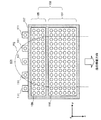
本実施形態に係る撮像部101は、例えば図2および図3に示したように、レンズアレイの一例であるマイクロレンズアレイ103と、近赤外光照射光源の一例である発光ダイオード(Light Emitting Diode:LED)111と、遮光壁117と、撮像素子119と、を主に備える。
For example, as illustrated in FIGS. 2 and 3, the
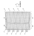
マイクロレンズアレイ103は、複数のマイクロレンズ109,110から構成されており、指紋部分画像を撮像する指紋撮像部分105と、静脈層部分画像を撮像する静脈層撮像部分107の2つに区画されている。例えば図2および図3に示したように、マイクロレンズアレイ103の指紋撮像部分105には、複数のマイクロレンズ109が格子状に配列されており、静脈層撮像部分107には、複数のマイクロレンズ110が格子状に配列されている。これらのマイクロレンズ109,110は、所定の基板上に格子状に配列されている。各マイクロレンズ109,110は、例えば図4に示したように、光入射面からマイクロレンズ109,110に入射した反射光および透過光14を、後述する撮像素子119に導光する。マイクロレンズアレイ103は、像面湾曲が少なく深さ方向のひずみがないレンズアレイであるため、このようなマイクロレンズアレイ103を用いることで、良好な画像データを得ることができる。
The
また、マイクロレンズ109の焦点位置は、指紋撮像部分105の撮像対象となる指紋が存在する表皮層の位置となるように設定され、マイクロレンズ110の焦点位置は、静脈層撮像部分107の撮像対象となる静脈が存在する静脈層の位置となるように設定される。
The focal position of the
人体の皮膚は、表皮層FG1、真皮層FG2および骨FG3等を含む皮下組織層の3層構造となっていることが知られているが、上述の静脈層は、真皮層FG2に存在している。真皮層は、指表面に対して0.1mm〜0.3mm程度の位置から2mm〜3mm程度の厚みで存在している層である。したがって、このような真皮層の存在位置(例えば、指表面から1.5mm〜2.0mm程度の位置)にマイクロレンズ110の焦点位置を設定することで、静脈層を透過した透過光を、効率よく集光することが可能となる。また、指紋は、表皮層FG1に存在し、他方、近赤外光は、照射した光量の60〜70%が表皮層FG1で反射してしまうことが知られている。そこで、マイクロレンズ109の焦点位置を表皮層FG1の位置に設定することで、表皮層FG1(すなわち、指紋)で反射した反射光を効率よく集光することが可能となる。なお、表皮層FG1近傍に位置する真皮層FG2の模様も指紋として利用できることが知られている。以下では、表皮層に存在する指紋と、真皮層の模様とを合わせて、指紋と称することとする。
It is known that the human skin has a three-layer structure of a subcutaneous tissue layer including the epidermis layer FG1, the dermis layer FG2, and the bone FG3. However, the vein layer described above exists in the dermis layer FG2. Yes. The dermis layer is a layer present at a thickness of about 2 mm to 3 mm from a position of about 0.1 mm to 0.3 mm with respect to the finger surface. Therefore, by setting the focal position of the
近赤外光照射光源の一例である発光ダイオード111は、例えば図2に示したようにマイクロレンズアレイ103の外側(より詳細には、マイクロレンズアレイ103の指紋撮像部分105側の端部)に複数配置され、指FGに対して所定の波長帯域を有する近赤外光を照射する。近赤外光は、身体組織に対して透過性が高い一方で、血液中のヘモグロビン(還元ヘモグロビン)に吸収されるという特徴を有するため、近赤外光を指や手のひらや手の甲に照射すると、指や手のひらや手の甲の内部に分布している静脈が影となって画像に現れる。画像に表れる静脈の影を、静脈パターンという。このような静脈パターンを良好に撮像するために、発光ダイオードは、約600nm〜1300nm程度の波長、好ましくは、700nm〜900nm程度の波長を有する近赤外光を照射する。
For example, as shown in FIG. 2, the
ここで、発光ダイオードが照射する近赤外光の波長が600nm未満または1300nm超過である場合には、血液中のヘモグロビンに吸収される割合が小さくなるため、良好な静脈パターンを得ることが困難となる。また、発光ダイオードが照射する近赤外光の波長が700nm〜900nm程度である場合には、近赤外光は、脱酸素化ヘモグロビンと酸素化ヘモグロビンの双方に対して特異的に吸収されるため、良好な静脈パターンを得ることができる。 Here, when the wavelength of near-infrared light irradiated by the light emitting diode is less than 600 nm or more than 1300 nm, it is difficult to obtain a good vein pattern because the proportion absorbed by hemoglobin in the blood becomes small. Become. Further, when the wavelength of near-infrared light emitted from the light emitting diode is about 700 nm to 900 nm, the near-infrared light is specifically absorbed by both deoxygenated hemoglobin and oxygenated hemoglobin. A good vein pattern can be obtained.
また、上述のような波長帯域を有する発光ダイオードを用いる代わりに、上述の波長帯域を含む光を射出可能な発光ダイオードと、射出された光を光学的に帯域制限するフィルタとを組み合わせたものを使用してもよい。 Also, instead of using a light emitting diode having the above wavelength band, a combination of a light emitting diode capable of emitting light including the above wavelength band and a filter for optically band limiting the emitted light is used. May be used.
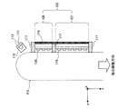
本実施形態に係る発光ダイオード111は、例えば図3および図4に示したように、発光ダイオードの光源部113と、光源部から射出した発光の光路を変更するプリズム部115と、を備える。プリズム部115は、例えばプリズムアレイ等から構成され、光源部113から射出した発光の光路を変更して、光の指向性を制御する。本実施形態に係る静脈認証装置10では、撮像制御部141が発光ダイオード111の光源部113およびプリズム部115を制御することにより、光源部111のオン・オフや、発光の指向性等を任意に制御することができる。
For example, as illustrated in FIGS. 3 and 4, the light-emitting
上述のように、生体おいて近赤外光の多くは、表皮層および真皮層で反射されるため、この反射光を利用することで、指紋および真皮層の模様(パターン)を取得することが可能である。しかしながら、真皮よりも更に深い位置に存在する静脈に関しては、この反射光の影響により、明瞭な画像を得ることは困難であった。 As described above, since most of near-infrared light in a living body is reflected by the epidermis layer and the dermis layer, the reflected light can be used to acquire a fingerprint and a pattern of the dermis layer. Is possible. However, it is difficult to obtain a clear image for the vein existing at a position deeper than the dermis due to the influence of the reflected light.
しかし、本実施形態に係る撮像部101では、例えば図4および図5に示したように、マイクロレンズアレイ103の指紋撮像部分105側の端部に発光ダイオード111を設けることで、反射光による表皮および真皮の撮像と、背面散乱光による静脈層の撮像とを実現することが可能となる。
However, in the
発光ダイオード111から射出された近赤外光は、例えば図4に示したように、指FGの表面(表皮層)FG1に向かって伝搬し、一部は表皮層FG1で反射され反射光としてマイクロレンズ109に入射することとなる。また、発光ダイオード111から射出された近赤外光の一部は、直接光12として指FGの内部に入射する。ここで、人体は良好な近赤外光の散乱体であるため、指FG内に入射した直接光12は四方に散乱しながら伝搬する。これらの散乱光の一部は、背面散乱光13として上述の静脈層20を背面から指表面に向かって透過し、透過光14としてマイクロレンズ109に入射することとなる。
For example, as shown in FIG. 4, near-infrared light emitted from the
さらに、発光ダイオード111の光源走査を撮像制御部141が制御することにより、最小限の面積でのコントラスト比を最適な状態にすることが可能となる。例えば、発光ダイオード111のプリズム部115の下部に配置された光源部113は、撮像部101の走査信号と関連付けされて撮像制御部141により駆動される。光源部113が点灯すると、例えば図5に示したように、光源部113の上部に配置されたプリズム部115によって、所定のエリアの照明が実行される。このとき、プリズム部115と撮像ラインが十分に離れていれば、入射した直接光12による静脈の背面散乱光13が効率的に取り出せることとなり、コントラスト比の高い静脈画像を得ることが出来る。また、例えば図5に示したように、走査ラインとともにそれぞれの発光ダイオード111を点滅させることで、撮像条件を常に満たす照明が可能となる。
Furthermore, the
さらに、指紋の撮像と静脈層の撮像とに関して、時間軸による相互相関を用いることで、各評価において安定性を持たせることが実現できる。またより信頼の置ける設定が行えることにより、認証精度や装置の安定性を実現できる。 Furthermore, with respect to fingerprint imaging and vein layer imaging, it is possible to achieve stability in each evaluation by using cross-correlation on the time axis. In addition, since more reliable settings can be made, authentication accuracy and device stability can be realized.
なお、上述の説明では、1系統の発光ダイオードアレイを用いた場合について説明を行ったが、2系統の発光ダイオードアレイを用いて近赤外光の照射を行ってもよい。すなわち、マイクロレンズアレイ103の指紋撮像部105側の端部に、指紋部分画像を撮像する際に用いる発光ダイオードアレイを配置し、マイクロレンズアレイ103の静脈層撮像部107側の端部に、静脈層部分画像を撮像する際に用いる発光ダイオードアレイを配置してもよい。この場合に、それぞれの発光ダイオードアレイは、それぞれの照射対象に適した照射条件となるように各種の設定がなされており、撮像制御部141は、それぞれの発光ダイオードアレイの照射を切り替える制御を行う。
In the above description, the case where one light emitting diode array is used has been described, but near infrared light irradiation may be performed using two light emitting diode arrays. That is, a light-emitting diode array used for capturing a fingerprint partial image is disposed at the end of the
また、指紋の撮像と静脈層の撮像とを、同一の波長を有する近赤外光により行ってもよく、指紋の撮像と静脈層の撮像とを、異なる波長を有する光を用いて行ってもよい。 Also, fingerprint imaging and vein layer imaging may be performed using near infrared light having the same wavelength, and fingerprint imaging and vein layer imaging may be performed using light having different wavelengths. Good.
ここで、マイクロレンズアレイ103と発光ダイオード111との間、および、指紋撮像部105と静脈層撮像部107との間には、例えば図2〜図4に示したように、遮光壁117が設けられる。この遮光壁117は、発光ダイオード111から射出された直接光12が直接マイクロレンズ109,110に入射しないように、直接光12を遮光する。
Here, between the
撮像素子119は、複数の受光素子が格子状に配置された撮像面を有し、マイクロレンズ109,110により集光された反射光および透過光14を基に、近赤外光による撮像データを生成する。本実施形態に係る撮像素子119として、例えば、CCD型画像センサや、C−MOS型画像センサ等を利用することができる。撮像素子119は、生成された撮像データを、後述する動きベクトル検出部151へと出力する。また、撮像素子119は、生成した撮像データを、後述する記憶部173に記憶してもよい。
The
なお、本実施形態に係る撮像部101では、指FGと撮像素子113との間に、被測定物である静脈層を透過した光(透過光14)に対して静脈撮像に適した光学的帯域制限を行うフィルタを、更に設けてもよい。
Note that, in the
以上、図2〜図4を参照しながら、本実施形態に係る撮像部101の構成について説明した。以下では、引き続き図1を参照しながら、本実施形態に係る静脈認証装置10の構成について、説明する。
The configuration of the
動きベクトル検出部151は、例えば、CPU、ROM、RAM等から構成され、撮像部101が生成した複数の指紋部分画像を解析して、指紋の動きベクトルを検出する。指紋の動きベクトルの検出は、例えば以下のような方法で行うことが可能である。撮像部101によって生成された指紋部分画像は、表皮や真皮に存在する指紋の凹凸のうち、隆起している部分(換言すれば、山の部分)の画像である。そこで、まず一枚の指紋部分画像に着目し、隣接する山と山の間の距離(または、谷と谷の間の距離)を算出する。続いて、別の指紋部分画像について、同様に山と山の間の距離、または、谷と谷の間の距離を算出する。得られた複数の指紋部分画像について、得られた山と山との距離に着目して解析を行うことで、指紋の動きベクトルを検出することが可能である。
The motion
また、上述の動きベクトルの検出方法以外にも、例えば、指紋認証技術において用いられる動きベクトルの検出方法を利用することが可能である。 In addition to the motion vector detection method described above, for example, a motion vector detection method used in fingerprint authentication technology can be used.
動きベクトル検出部151は、このようにして検出された指紋の動きベクトルを、後述する画像合成部153に出力する。また、動きベクトル検出部151は、検出した動きベクトルを、後述する記憶部173に記録してもよい。
The motion
画像合成部153は、例えば、CPU、ROM、RAM等から構成され、動きベクトル検出部151により検出された動きベクトルに基づいて、指紋画像および静脈画像を合成する。この画像合成部153は、指紋画像合成部155と、静脈画像合成部157と、を更に備える。
The
指紋画像合成部155は、動きベクトル検出部151から伝送された動きベクトルに基づいて撮像部101から伝送された複数の指紋部分画像を合成し、指紋の撮像画像を生成する。また、画像の合成に際して、撮像部101から伝送された指紋部分画像が鏡像になっている場合には、指紋画像合成部155は、各指紋部分画像を反転処理した後に合成処理を行ってもよい。また、撮像部101から伝送された指紋部分画像に対して、収差補正や輝度分布の補正等の補正処理を施す必要がある場合には、指紋画像合成部155は、合成前の指紋部分画像や合成後の撮像画像に対して各種の補正処理を行ってもよい。
The fingerprint
指紋画像合成部155は、合成した指紋の撮像画像を指紋パターンとして、後述する認証部161に出力する。また、指紋画像合成部155は、合成した指紋の撮像画像を、後述する記憶部173に記録してもよい。
The fingerprint
静脈画像合成部157は、動きベクトル検出部151から伝送された動きベクトルに基づいて撮像部101から伝送された複数の静脈層部分画像を合成し、静脈層画像を生成する。また、画像の合成に際して、撮像部101から伝送された静脈層部分画像が鏡像になっている場合には、静脈画像合成部157は、各静脈層部分画像を反転処理した後に合成処理を行ってもよい。また、撮像部101から伝送された静脈層部分画像に対して、収差補正や輝度分布の補正等の補正処理を施す必要がある場合には、静脈画像合成部157は、合成前の静脈層部分画像や合成後の撮像画像に対して各種の補正処理を行ってもよい。
The vein
静脈画像合成部157は、合成した静脈層の撮像画像を、後述する静脈パターン抽出部159に出力する。また、静脈画像合成部157は、合成した静脈層の撮像画像を、後述する記憶部173に記録してもよい。
The vein
静脈パターン抽出部159は、例えば、CPU、ROM、RAM等から構成され、例えば、静脈画像合成部157から伝送される静脈層の撮像データに対して、静脈パターン抽出の前処理を行なう機能と、静脈パターンの抽出を行なう機能と、静脈パターン抽出の後処理を行なう機能と、を備える。
The vein
ここで、上記の静脈パターン抽出の前処理は、例えば、静脈層の撮像データから指の輪郭を検出し、静脈層の撮像データのどの位置に指があるかを識別する処理や、検出した指の輪郭を利用して撮像データを回転させて、静脈層の撮像データの角度(撮像画像の角度)を補正する処理等を含む。 Here, the pre-processing of the vein pattern extraction described above includes, for example, processing for detecting the contour of the finger from the vein layer imaging data and identifying the position of the finger in the vein layer imaging data, This includes processing for rotating the imaging data using the contour of the image to correct the angle of the imaging data of the vein layer (angle of the captured image).
また、上記の静脈パターンの抽出は、輪郭の検出や角度の補正が終了した静脈層の撮像データに対して差分フィルタを適用することで行なわれる。差分フィルタは、注目している画素とその周囲の画素について、注目している画素と周囲の画素との差分が大きな部分で、大きな値を出力値として出力するフィルタである。換言すれば、差分フィルタとは、注目している画素とその近傍の階調値の差分を用いた演算により、画像中の線や縁を強調するフィルタである。 The vein pattern is extracted by applying a difference filter to the image data of the vein layer for which contour detection and angle correction have been completed. The difference filter is a filter that outputs a large value as an output value at a portion where the difference between the pixel of interest and the surrounding pixels is large between the pixel of interest and the surrounding pixels. In other words, the difference filter is a filter that emphasizes lines and edges in an image by calculation using a difference between a pixel of interest and a gradation value in the vicinity thereof.
一般的に、2次元平面の格子点(x,y)を変数とする画像データu(x,y)に対してフィルタh(x,y)を用いてフィルタ処理を行なうと、以下の式1に示すように、画像データν(x,y)を生成する。ここで、以下の式2において、‘*’は畳込み積分(コンボリューション)を表す。
In general, when filter processing is performed on image data u (x, y) having a lattice point (x, y) on a two-dimensional plane as a variable using a filter h (x, y), the following

本実施形態に係る静脈パターンの抽出では、上記の差分フィルタとして、1次空間微分フィルタや2次空間微分フィルタ等の微分フィルタを用いてもよい。1次空間微分フィルタは、注目している画素について、横方向と縦方向の隣接している画素の階調値の差分を算出するフィルタであり、2次空間微分フィルタは、注目している画素について、階調値の差分の変化量が大きくなっている部分を抽出するフィルタである。 In the extraction of the vein pattern according to the present embodiment, a differential filter such as a primary spatial differential filter or a secondary spatial differential filter may be used as the differential filter. The primary spatial differential filter is a filter that calculates a difference between gradation values of adjacent pixels in the horizontal direction and the vertical direction for the pixel of interest, and the secondary spatial differential filter is the pixel of interest. Is a filter that extracts a portion where the amount of change in the difference in gradation value is large.
上記の2次空間微分フィルタとして、例えば、以下に示すLog(Laplacian of Gaussian)フィルタを用いることが可能である。Logフィルタ(式3)は、ガウス関数を用いた平滑化フィルタであるガウシアン(Gaussian)フィルタ(式2)の2次微分で表される。ここで、以下の式2において、σはガウス関数の標準偏差を表し、ガウシアンフィルタの平滑化の度合いを表す変数である。また、以下の式3におけるσは、式2と同様にガウス関数の標準偏差を表すパラメータであり、σの値を変化させることで、Logフィルタ処理を行なった場合の出力値を変化させることができる。 As the second-order spatial differential filter, for example, the following Log (Laplacian of Gaussian) filter can be used. The Log filter (Equation 3) is expressed by the second derivative of a Gaussian filter (Equation 2) that is a smoothing filter using a Gaussian function. Here, in Expression 2 below, σ represents a standard deviation of a Gaussian function, and is a variable representing the degree of smoothing of the Gaussian filter. In addition, σ in Equation 3 below is a parameter that represents the standard deviation of the Gaussian function as in Equation 2, and by changing the value of σ, the output value when the Log filter processing is performed can be changed. it can.
また、上記の静脈パターン抽出の後処理は、例えば、差分フィルタ適用後の画像データに対してなされる閾値処理や、2値化処理や、細線化処理等を含む。かかる後処理を経て、静脈パターンのスケルトンを抽出することが可能となる。 Further, the post-processing of the vein pattern extraction includes, for example, threshold processing, binarization processing, thinning processing, and the like performed on the image data after application of the difference filter. Through such post-processing, it is possible to extract a skeleton of a vein pattern.
静脈パターン抽出部159は、このようにして抽出した静脈パターンやスケルトンを、後述する認証部161等に伝送する。また、静脈パターン抽出部159は、抽出した静脈パターンやスケルトンを、後述する記憶部173に記憶してもよい。なお、静脈パターン抽出部159は、上述の各処理を行なうに当たって生成したパラメータや処理の途中経過等を、記憶部173に記憶してもよい。
The vein
認証部161は、例えば、CPU、ROM、RAM等から構成され、静脈パターン抽出部159により生成された静脈パターンをテンプレートとして登録したり、静脈パターン抽出部159により生成された静脈パターンを既に登録されているテンプレートと照合して、静脈パターンの認証を行ったりする。また、認証部161は、指紋画像合成部155により生成された指紋パターンをテンプレートとして登録したり、指紋画像合成部155により生成された指紋パターンを既に登録されているテンプレートと照合して、指紋パターンの認証を行ったりする。かかる認証部161は、例えば、指紋パターン登録部163と、指紋パターン認証部165と、静脈パターン登録部167と、静脈パターン認証部169と、を更に備える。
The
指紋パターン登録部163は、指紋画像合成部155により生成された指紋パターンを、テンプレートとして登録する。また、登録指紋パターンの登録に際しては、指紋パターンだけでなく、指紋パターンを有する個人を特定する他のデータ(例えば、静脈データ、顔画像データ、虹彩データ、声紋データ等)を指紋パターンに関連づけて記憶してもよい。また、テンプレートとして登録される登録指紋パターンは、例えば、CBEFF(Common Biometric Exchange File Format:共通バイオメトリック交換ファイルフォーマットフレームワーク)等の規格に則ったヘッダ情報を有していてもよい。
The fingerprint
指紋パターン認証部165は、指紋画像合成部155により生成された指紋パターンと、既に記録されている指紋パターンのテンプレートとに基づいて、生成された指紋パターンの認証を行なう。指紋パターン認証部165は、後述する記憶部173に対して登録指紋パターンの開示を要求し、取得した登録指紋パターンと、指紋画像合成部155から伝送された指紋パターンとの比較を行なう。登録指紋パターンと伝送された指紋パターンとの比較は、例えば以下に示す相関係数を算出し、算出した相関係数に基づいて実行することが可能である。指紋パターン認証部165は、比較の結果登録指紋パターンと伝送された指紋パターンが類似している場合には、伝送された指紋パターンを認証し、類似していない場合には、認証を行なわない。
The fingerprint
静脈パターン登録部167は、静脈パターン抽出部159により生成された静脈パターンを、テンプレートとして後述する記憶部173に登録する。また、登録静脈パターンの登録に際しては、静脈パターンだけでなく、静脈パターンを有する個人を特定する他のデータ(例えば、指紋データ、顔画像データ、虹彩データ、声紋データ等)を静脈パターンに関連づけて記憶してもよい。また、テンプレートとして登録される登録静脈パターンは、例えば、CBEFF(Common Biometric Exchange File Format:共通バイオメトリック交換ファイルフォーマットフレームワーク)等の規格に則ったヘッダ情報を有していてもよい。
The vein
静脈パターン認証部169は、静脈パターン抽出部159により生成された静脈パターンと、既に記録されている静脈パターンのテンプレートとに基づいて、生成された静脈パターンの認証を行なう。静脈パターン認証部169は、後述する記憶部173に対して登録静脈パターンの開示を要求し、取得した登録静脈パターンと、静脈パターン抽出部159から伝送された静脈パターンとの比較を行なう。登録静脈パターンと伝送された静脈パターンとの比較は、例えば以下に示す相関係数を算出し、算出した相関係数に基づいて実行することが可能である。静脈パターン認証部169は、比較の結果登録静脈パターンと伝送された静脈パターンが類似している場合には、伝送された静脈パターンを認証し、類似していない場合には、認証を行なわない。
The vein
相関係数は、以下の式4で定義されるものであり、2つのデータx={xi},y={yi}間の類似度を示す統計学指標であって、−1から1までの実数値をとる。相関係数が1に近い値を示す場合には、2つのデータは類似していることを示し、相関係数が0に近い値を示す場合には、2つのデータは類似していないことを示す。また、相関係数が−1に近い値を示す場合には、2つのデータの符号が反転しているような場合を示す。 The correlation coefficient is defined by Equation 4 below, and is a statistical index indicating the similarity between two data x = {x i }, y = {y i }, and is from −1 to 1 Take real values up to. When the correlation coefficient indicates a value close to 1, it indicates that the two data are similar. When the correlation coefficient indicates a value close to 0, the two data indicate that they are not similar. Show. Further, when the correlation coefficient shows a value close to -1, the case where the signs of the two data are inverted is shown.
また、指紋パターン認証部165および静脈パターン認証部169は、認証結果を認証時刻等と関連づけて、認証履歴として記憶部173に記録してもよい。かかる認証履歴を生成することで、誰がいつ指紋パターンや静脈パターンの認証を要求したのか、ひいては、誰がいつ静脈認証装置10を利用したのか、を知ることが可能となる。
The fingerprint
処理部171は、例えば、CPU、ROM、RAM等から構成され、認証部161から出力される静脈パターンの認証結果に応じて、所定の処理を実行する。すなわち、処理部171は、認証部161から静脈パターンの認証が成功した旨の通知を受けると、実行が制限されている所定の処理の制限を解除して、処理を実行する。また、処理部171は、静脈パターンの認証結果に加えて指紋パターンの認証結果に応じて、所定の処理を実行してもよい。指紋パターンによる認証と、静脈パターンによる認証とを二重に行うことで、高いセキュリティレベルを実現することができる。
The
記憶部173は、指紋パターン登録部163から登録要請のあった登録指紋パターンや、当該登録指紋パターンに関連付けられた他のデータを記憶する。また、記憶部173は、静脈パターン登録部167から登録要請のあった登録静脈パターンや、当該登録静脈パターンに関連付けられた他のデータを記憶する。また、これらのデータ以外にも、撮像部101が生成した撮像データや、静脈パターン抽出部159が抽出した静脈パターン等を記憶することも可能である。更に、これらのデータ以外にも、静脈認証装置10が、何らかの処理を行う際に保存する必要が生じた様々なパラメータや処理の途中経過等、または、各種のデータベース等を、適宜記憶することが可能である。この記憶部173は、撮像部101、撮像制御部141、動きベクトル検出部151、画像合成部153、静脈パターン抽出部159、認証部161、処理部171等が、自由に読み書きを行うことが可能である。
The
以上、本実施形態に係る静脈認証装置10の機能の一例を示した。上記の各構成要素は、汎用的な部材や回路を用いて構成されていてもよいし、各構成要素の機能に特化したハードウェアにより構成されていてもよい。また、各構成要素の機能を、CPU等が全て行ってもよい。従って、本実施形態を実施する時々の技術レベルに応じて、適宜、利用する構成を変更することが可能である。
Heretofore, an example of the function of the
なお、本実施形態に係る静脈認証装置10は、例えば、コンピュータやサーバ等の情報処理装置、携帯電話やPHS等の携帯端末や携帯情報端末(PDA)、現金自動預払機(ATM)、入退室管理装置、ゲーム機器やゲーム機器のコントローラ等の各種装置に実装されてもよい。
The
また、上述の説明では、テンプレートとして登録される登録静脈パターンが、静脈認証装置10内に記録される場合について説明したが、登録静脈パターンは、DVDメディア、HD−DVDメディア、Blu−rayメディア、コンパクトフラッシュ(登録商標)、メモリースティック、または、SDメモリカード等の記録媒体や、非接触型ICチップを搭載したICカードまたは電子機器等に記録されてもよく、静脈認証装置10とインターネット等の通信網を介して接続されたサーバに記録されてもよい。
In the above description, the registered vein pattern registered as a template has been described as being recorded in the
<本実施形態に係る静脈認証方法について>
続いて、図6および図7を参照しながら、本実施形態に係る静脈認証方法について、詳細に説明する。図6は、本実施形態に係る静脈認証方法を説明するための説明図であり、図7は、本実施形態に係る静脈認証方法を説明するための流れ図である。
<About the vein authentication method according to this embodiment>
Subsequently, the vein authentication method according to the present embodiment will be described in detail with reference to FIGS. 6 and 7. FIG. 6 is an explanatory diagram for explaining the vein authentication method according to this embodiment, and FIG. 7 is a flowchart for explaining the vein authentication method according to this embodiment.
まず、本実施形態に係る静脈認証装置10の撮像部101は、撮像部101に載置された指に対して近赤外光を照射し、表皮や真皮に存在する指紋の撮影と、指内部に位置する静脈層の撮像を連続的に行う(ステップS101)。撮像部101によって生成されるそれぞれの撮像データは、本実施形態に係る静脈認証装置10の動きベクトル検出部151に出力される。
First, the
次に、動きベクトル検出部151は、撮像部101から出力された複数の指紋部分画像FP1に基づいて、指紋の動きベクトルを検出する(ステップS103)。動きベクトル検出部151は、動きベクトルの検出処理が終了すると、検出した動きベクトルを、画像合成部153に出力する。
Next, the motion
続いて、画像合成部153の指紋画像合成部155は、動きベクトル検出部151から出力された動きベクトルに基づいて複数の指紋部分画像FP1を合成し、指紋の撮像画像FPを生成する(ステップS105)。指紋画像合成部155は、指紋の撮像画像の合成が終了すると、生成した指紋の撮像画像を指紋パターンとして認証部161へと出力する。
Subsequently, the fingerprint
次に、画像合成部153の静脈画像合成部157は、動きベクトル検出部151から出力された動きベクトルに基づいて複数の静脈層部分画像を合成し、静脈層の撮像画像を生成する(ステップS107)。静脈画像合成部157は、静脈層の撮像画像の合成が終了すると、生成した静脈層の撮像画像を、静脈パターン抽出部159へと出力する。
Next, the vein
続いて、静脈パターン抽出部159は、静脈画像合成部157から伝送された撮像データから、静脈パターンを抽出する(ステップS109)。静脈パターンの抽出が終了すると、静脈パターン抽出部159は、抽出した静脈パターンを、認証部161に出力する。
Subsequently, the vein
次に、認証部161は、静脈パターン抽出部159から出力された静脈パターンに基づいて、静脈パターンの認証処理を行う(ステップS111)。ここで、静脈認証装置10を使用しているユーザが、静脈パターンの登録を希望している場合には、認証部161の静脈パターン登録部167は、静脈パターン抽出部159から出力された静脈パターンを登録静脈パターンとして記憶部173に記録する。また、静脈認証装置10を使用しているユーザが、静脈パターンの認証を希望している場合には、認証部161の静脈パターン認証部169は、既に登録されている登録静脈パターンと、静脈パターン抽出部159から出力された静脈パターンとを比較し、静脈パターン抽出部159から出力された静脈パターンが登録静脈パターンである場合には、認証が成功した旨を処理部171に通知する。また、静脈パターン抽出部159から出力された静脈パターンが登録静脈パターンと一致しない場合には、認証部161は、認証が失敗した旨を処理部171に通知する。
Next, the
また、認証部161は、静脈パターンの登録処理や認証処理に加えて、指紋画像合成部155から伝送された指紋パターンについて、登録処理や認証処理を行ってもよい。
The
続いて、処理部171は、認証部161から通知される認証結果に応じて、所定の処理を実行する(ステップS113)。すなわち、認証部161から認証が成功した旨の通知を受信すると、処理部171は、実行が制限されている所定の処理の制限を解除し、処理を実行する。また、認証部161から認証が失敗した旨の通知を受信すると、処理部171は、処理を終了する。
Subsequently, the
<静脈認証装置のハードウェア構成について>
次に、図8を参照しながら、本実施形態に係る静脈認証装置10のハードウェア構成について、詳細に説明する。図8は、本実施形態に係る静脈認証装置10のハードウェア構成を説明するためのブロック図である。
<Hardware configuration of vein authentication device>
Next, the hardware configuration of the
静脈認証装置10は、主に、CPU901と、ROM903と、RAM905と、ホストバス907と、ブリッジ909と、外部バス911と、インターフェース913と、入力装置915と、出力装置917と、ストレージ装置919と、ドライブ921と、接続ポート923と、通信装置925とを備える。
The
CPU901は、演算処理装置および制御装置として機能し、ROM903、RAM905、ストレージ装置919、またはリムーバブル記録媒体927に記録された各種プログラムに従って、静脈認証装置10内の動作全般またはその一部を制御する。ROM903は、CPU901が使用するプログラムや演算パラメータ等を記憶する。RAM905は、CPU901の実行において使用するプログラムや、その実行において適宜変化するパラメータ等を一次記憶する。これらはCPUバス等の内部バスにより構成されるホストバス907により相互に接続されている。
The
ホストバス907は、ブリッジ909を介して、PCI(Peripheral Component Interconnect/Interface)バスなどの外部バス911に接続されている。
The
入力装置915は、例えば、マウス、キーボード、タッチパネル、ボタン、スイッチおよびレバーなどユーザが操作する操作手段である。また、入力装置915は、例えば、赤外線やその他の電波を利用したリモートコントロール手段(いわゆる、リモコン)であってもよいし、静脈認証装置10の操作に対応した携帯電話やPDA等の外部接続機器929であってもよい。さらに、入力装置915は、例えば、上記の操作手段を用いてユーザにより入力された情報に基づいて入力信号を生成し、CPU901に出力する入力制御回路などから構成されている。静脈認証装置10のユーザは、この入力装置915を操作することにより、静脈認証装置10に対して各種のデータを入力したり処理動作を指示したりすることができる。
The
出力装置917は、例えば、CRTディスプレイ装置、液晶ディスプレイ装置、プラズマディスプレイ装置、ELディスプレイ装置およびランプなどの表示装置や、スピーカおよびヘッドホンなどの音声出力装置や、プリンタ装置、携帯電話、ファクシミリなど、取得した情報をユーザに対して視覚的または聴覚的に通知することが可能な装置で構成される。出力装置917は、例えば、静脈認証装置10が行った各種処理により得られた結果を出力する。具体的には、表示装置は、静脈認証装置10が行った各種処理により得られた結果を、テキストまたはイメージで表示する。他方、音声出力装置は、再生された音声データや音響データ等からなるオーディオ信号をアナログ信号に変換して出力する。
The
ストレージ装置919は、静脈認証装置10の記憶部の一例として構成されたデータ格納用の装置であり、例えば、HDD(Hard Disk Drive)等の磁気記憶部デバイス、半導体記憶デバイス、光記憶デバイス、または光磁気記憶デバイス等により構成される。このストレージ装置919は、CPU901が実行するプログラムや各種データ、および外部から取得した音響信号データや画像信号データなどを格納する。
The
ドライブ921は、記録媒体用リーダライタであり、静脈認証装置10に内蔵、あるいは外付けされる。ドライブ921は、装着されている磁気ディスク、光ディスク、光磁気ディスク、または半導体メモリ等のリムーバブル記録媒体927に記録されている情報を読み出して、RAM905に出力する。また、ドライブ921は、装着されている磁気ディスク、光ディスク、光磁気ディスク、または半導体メモリ等のリムーバブル記録媒体927に記録を書き込むことも可能である。リムーバブル記録媒体927は、例えば、DVDメディア、HD−DVDメディア、Blu−rayメディア、コンパクトフラッシュ(登録商標)(CompactFlash:CF)、メモリースティック、または、SDメモリカード(Secure Digital memory card)等である。また、リムーバブル記録媒体927は、例えば、非接触型ICチップを搭載したICカード(Integrated Circuit card)または電子機器等であってもよい。
The
接続ポート923は、例えば、USB(Universal Serial Bus)ポート、i.Link等のIEEE1394ポート、SCSI(Small Computer System Interface)ポート、RS−232Cポート、光オーディオ端子、HDMI(High−Definition Multimedia Interface)ポート等の、機器を静脈認証装置10に直接接続するためのポートである。この接続ポート923に外部接続機器929を接続することで、静脈認証装置10は、外部接続機器929から直接音響信号データや画像信号データを取得したり、外部接続機器929に音響信号データや画像信号データを提供したりする。
The
通信装置925は、例えば、通信網931に接続するための通信デバイス等で構成された通信インターフェースである。通信装置925は、例えば、有線または無線LAN(Local Area Network)、Bluetooth、またはWUSB(Wireless USB)用の通信カード、光通信用のルータ、ADSL(Asymmetric Digital Subscriber Line)用のルータ、または、各種通信用のモデム等である。この通信装置925は、例えば、インターネットや他の通信機器との間で音響信号等を送受信することができる。また、通信装置925に接続される通信網931は、有線または無線によって接続されたネットワーク等により構成され、例えば、インターネット、家庭内LAN、赤外線通信、ラジオ波通信または衛星通信等であってもよい。
The
以上、本発明の各実施形態に係る静脈認証装置10の機能を実現可能なハードウェア構成の一例を示した。上記の各構成要素は、汎用的な部材を用いて構成されていてもよいし、各構成要素の機能に特化したハードウェアにより構成されていてもよい。従って、本実施形態を実施する時々の技術レベルに応じて、適宜、利用するハードウェア構成を変更することが可能である。
Heretofore, an example of the hardware configuration capable of realizing the function of the
以上説明したように、本実施形態に係る静脈認証装置10および静脈認証方法では、平面構造での反射散乱光を利用することで、指静脈認証を平面構造に実装することが可能となり、ひいては、装置の小型化を図るとともに、局部的な画像から広範囲の静脈画像を撮像することが可能な接触型の静脈認証装置を実現することができる。
As described above, in the
従来の静脈認証装置では、撮像エリアに対して十分な画像のコントラスト比を確保するために、近赤外光照射光源に120度程度の角度をつける必要があり、この光源を実施する装置全体が大きなものになる傾向があった。また、静脈パターンが小さい面積では単純であるという理由から、静脈パターンから十分な精度の動きベクトルを算出することは困難であった。しかし、本実施形態に係る静脈認証装置10では、表皮・真皮の撮像画像と、静脈層の撮像画像を同時に得ることが可能であるため、十分な精度の動きベクトルを検出可能な表皮・真皮の撮像画像から動きベクトルを算出し、算出した動きベクトルを静脈層の撮像画像の合成に利用することができる。このため、小さなセンサで広範囲の静脈画像を取得することが可能となる。
In the conventional vein authentication device, in order to ensure a sufficient image contrast ratio with respect to the imaging area, it is necessary to make an angle of about 120 degrees with respect to the near-infrared light irradiation light source. There was a tendency to become big. In addition, it is difficult to calculate a motion vector with sufficient accuracy from a vein pattern because the vein pattern is simple in a small area. However, since the
以上、添付図面を参照しながら本発明の好適な実施形態について説明したが、本発明はかかる例に限定されないことは言うまでもない。当業者であれば、特許請求の範囲に記載された範疇内において、各種の変更例または修正例に想到し得ることは明らかであり、それらについても当然に本発明の技術的範囲に属するものと了解される。 As mentioned above, although preferred embodiment of this invention was described referring an accompanying drawing, it cannot be overemphasized that this invention is not limited to this example. It will be apparent to those skilled in the art that various changes and modifications can be made within the scope of the claims, and these are naturally within the technical scope of the present invention. Understood.
例えば、上述の実施形態においては、指を図中のx軸方向に走査する場合について説明したが、指を図中のy軸方向に走査する場合であっても、同様の効果を得ることが可能である。 For example, in the above-described embodiment, the case where the finger is scanned in the x-axis direction in the figure has been described, but the same effect can be obtained even when the finger is scanned in the y-axis direction in the figure. Is possible.
10 静脈認証装置
12 直接光
13 背面散乱光
14 反射光および透過光
101 撮像部
103 マイクロレンズアレイ
105 指紋撮像部分
107 静脈層撮像部分
109,110 マイクロレンズ
111 発光ダイオード
113 光源部
115 プリズム部
117 遮光壁
119 撮像素子
141 撮像制御部
151 動きベクトル検出部
153 画像合成部
155 指紋画像合成部
157 静脈画像合成部
159 静脈パターン抽出部
161 認証部
163 指紋パターン登録部
165 指紋パターン認証部
167 静脈パターン登録部
169 静脈パターン認証部
171 処理部
173 記憶部
FG 指
FG1 表皮
FG2 真皮
FG3 骨
FP 指紋パターン
FP1 指紋部分画像
DESCRIPTION OF
Claims (4)
複数の前記指紋の一部を撮像した画像に基づいて、前記指紋の動きベクトルを検出する動きベクトル検出部と、
前記指紋の動きベクトルに基づいて前記指紋の一部を撮像した画像を合成し、指紋の撮像画像を生成するとともに、前記指紋の動きベクトルに基づいて前記静脈層の一部を撮像した画像を合成して前記静脈層の撮像画像を生成する画像合成部と、
前記静脈層の撮像画像から静脈パターンを抽出する静脈パターン抽出部と、
前記撮像部を制御する撮像制御部と、
を備え、
前記撮像部は、
複数の受光レンズがアレイ状に配設されており、前記反射光を受光する領域と前記静脈層を透過した透過光を受光する領域に区画されたレンズアレイと、
前記レンズアレイの前記反射光を受光する領域側の端部に設けられ、前記指表面に対して近赤外光を照射する近赤外光照射光源と、
前記反射光に基づいて前記指紋の一部を撮像した画像を生成するとともに、前記透過光に基づいて前記静脈層の一部を撮像した画像を生成する撮像素子と、
を備え、
前記近赤外光照射光源は、前記近赤外光を射出する光源部と、前記光源部から射出された前記近赤外光の光路を変更するプリズム部と、から構成されており、
前記撮像制御部は、前記プリズム部を制御することにより、前記近赤外光照射光源から射出される前記近赤外光の指向性を制御し、前記近赤外光照射光源から射出される前記近赤外光の照射を、前記指紋の一部を撮像した画像を取得するための照射と、前記静脈層の一部を撮像した画像を取得するための照射とに切り替える、静脈画像取得装置。 The finger surface is irradiated with near-infrared light and diffused inside the finger while continuously imaging a part of the fingerprint existing on the finger surface or the finger by reflected light reflected on the finger surface or inside the finger. An imaging unit that continuously images a portion of the vein layer located inside the finger by the near infrared light that has been
A motion vector detection unit that detects a motion vector of the fingerprint based on an image obtained by imaging a part of the plurality of fingerprints;
An image obtained by imaging a part of the fingerprint based on the motion vector of the fingerprint is synthesized to generate a captured image of the fingerprint, and an image obtained by imaging a part of the vein layer is synthesized based on the motion vector of the fingerprint. An image synthesis unit for generating a captured image of the vein layer;
A vein pattern extraction unit that extracts a vein pattern from the captured image of the vein layer;
An imaging control unit for controlling the imaging unit;
With
The imaging unit
A plurality of light receiving lenses are arranged in an array, and a lens array partitioned into a region that receives the reflected light and a region that receives the transmitted light that has passed through the vein layer,
A near-infrared light irradiation light source that is provided at an end of the lens array on the region side that receives the reflected light and irradiates near-infrared light on the finger surface;
An image sensor that generates an image of a part of the fingerprint based on the reflected light, and generates an image of a part of the vein layer based on the transmitted light;
Equipped with a,
The near-infrared light irradiation light source includes a light source unit that emits the near-infrared light, and a prism unit that changes an optical path of the near-infrared light emitted from the light source unit,
The imaging control unit controls the directivity of the near infrared light emitted from the near infrared light irradiation light source by controlling the prism unit, and the light emitted from the near infrared light irradiation light source A vein image acquisition device that switches irradiation of near infrared light to irradiation for acquiring an image obtained by imaging a part of the fingerprint and irradiation for acquiring an image obtained by imaging a part of the vein layer .
前記透過光を受光する領域に位置する前記受光レンズの焦点位置は、前記静脈層の位置に設定されている、請求項1に記載の静脈画像取得装置。 The focal position of the light receiving lens located in the area that receives the reflected light is set to the position of the finger surface,
The vein image acquisition apparatus according to claim 1, wherein a focus position of the light receiving lens located in a region that receives the transmitted light is set to a position of the vein layer.
指表面に近赤外光を照射し、前記指表面または指内部で反射した反射光により前記指表面または前記指内部に存在する指紋の一部を連続的に撮像しつつ、前記指内部で拡散された前記近赤外光により当該指内部に位置する静脈層の一部を連続的に撮像する撮像部により、前記指表面の一部を連続的に撮像するステップと、
複数の前記指紋の一部を撮像した画像に基づいて、前記指紋の動きベクトルを検出する動きベクトル検出ステップと、
前記指紋の動きベクトルに基づいて前記指紋の一部を撮像した画像を合成し、指紋の撮像画像を生成するとともに、前記指紋の動きベクトルに基づいて前記静脈層の一部を撮像した画像を合成して前記静脈層の撮像画像を生成する画像合成ステップと、
前記静脈層の撮像画像から静脈パターンを抽出する静脈パターン抽出ステップと、
を含み、
前記撮像部は、複数の受光レンズがアレイ状に配設されており、前記反射光を受光する領域と前記静脈層を透過した透過光を受光する領域に区画されたレンズアレイと、
前記レンズアレイの前記反射光を受光する領域側の端部に設けられ、前記指表面に対して近赤外光を照射する近赤外光照射光源と、
前記反射光に基づいて前記指紋の一部を撮像した画像を生成するとともに、前記透過光に基づいて前記静脈層の一部を撮像した画像を生成する撮像素子と、
を備え、
前記近赤外光照射光源は、前記近赤外光を射出する光源部と、前記光源部から射出された前記近赤外光の光路を変更するプリズム部と、から構成されており、
前記指表面の一部を連続的に撮像するステップでは、前記プリズム部が制御されることにより、前記近赤外光照射光源から射出される前記近赤外光の指向性が制御され、前記近赤外光照射光源から射出される前記近赤外光の照射が、前記指紋の一部を撮像した画像を取得するための照射と、前記静脈層の一部を撮像した画像を取得するための照射とに切り替えられる、静脈画像取得方法。
A vein image acquisition method for irradiating a finger surface with near infrared light and extracting a vein pattern of a vein layer located inside the finger,
The finger surface is irradiated with near-infrared light and diffused inside the finger while continuously imaging a part of the fingerprint existing on the finger surface or the finger by reflected light reflected on the finger surface or inside the finger. A step of continuously imaging a part of the finger surface by an imaging unit that continuously images a part of the vein layer located inside the finger by the near infrared light ,
A motion vector detection step of detecting a motion vector of the fingerprint based on an image obtained by imaging a part of the plurality of fingerprints;
An image obtained by imaging a part of the fingerprint based on the motion vector of the fingerprint is synthesized to generate a captured image of the fingerprint, and an image obtained by imaging a part of the vein layer is synthesized based on the motion vector of the fingerprint. And an image synthesis step for generating a captured image of the vein layer;
A vein pattern extraction step of extracting a vein pattern from the captured image of the vein layer;
Only including,
The imaging unit includes a plurality of light receiving lenses arranged in an array, and a lens array partitioned into a region that receives the reflected light and a region that receives transmitted light that has passed through the vein layer,
A near-infrared light irradiation light source that is provided at an end of the lens array on the region side that receives the reflected light and irradiates near-infrared light on the finger surface;
An image sensor that generates an image of a part of the fingerprint based on the reflected light, and generates an image of a part of the vein layer based on the transmitted light;
With
The near-infrared light irradiation light source includes a light source unit that emits the near-infrared light, and a prism unit that changes an optical path of the near-infrared light emitted from the light source unit,
In the step of continuously imaging a part of the finger surface, the prism unit is controlled to control the directivity of the near-infrared light emitted from the near-infrared light irradiation light source. Irradiation of the near-infrared light emitted from an infrared light irradiation light source is for obtaining an image obtained by imaging a part of the fingerprint, and for obtaining an image obtained by imaging a part of the vein layer. A vein image acquisition method that can be switched to irradiation .
Priority Applications (3)
| Application Number | Priority Date | Filing Date | Title |
|---|---|---|---|
| JP2008006944A JP5292821B2 (en) | 2008-01-16 | 2008-01-16 | Vein image acquisition device and vein image acquisition method |
| US12/352,965 US8111878B2 (en) | 2008-01-16 | 2009-01-13 | Vein authentication device and vein authentication method |
| CN2009100012987A CN101485570B (en) | 2008-01-16 | 2009-01-16 | Vein authentication device and vein authentication method |
Applications Claiming Priority (1)
| Application Number | Priority Date | Filing Date | Title |
|---|---|---|---|
| JP2008006944A JP5292821B2 (en) | 2008-01-16 | 2008-01-16 | Vein image acquisition device and vein image acquisition method |
Publications (3)
| Publication Number | Publication Date |
|---|---|
| JP2009165630A JP2009165630A (en) | 2009-07-30 |
| JP2009165630A5 JP2009165630A5 (en) | 2011-02-24 |
| JP5292821B2 true JP5292821B2 (en) | 2013-09-18 |
Family
ID=40888748
Family Applications (1)
| Application Number | Title | Priority Date | Filing Date |
|---|---|---|---|
| JP2008006944A Expired - Fee Related JP5292821B2 (en) | 2008-01-16 | 2008-01-16 | Vein image acquisition device and vein image acquisition method |
Country Status (3)
| Country | Link |
|---|---|
| US (1) | US8111878B2 (en) |
| JP (1) | JP5292821B2 (en) |
| CN (1) | CN101485570B (en) |
Cited By (1)
| Publication number | Priority date | Publication date | Assignee | Title |
|---|---|---|---|---|
| CN111968285A (en) * | 2020-08-05 | 2020-11-20 | 烟台南山学院 | Students' dormitory information management collection system |
Families Citing this family (41)
| Publication number | Priority date | Publication date | Assignee | Title |
|---|---|---|---|---|
| JP4910923B2 (en) * | 2007-07-20 | 2012-04-04 | ソニー株式会社 | Imaging apparatus, imaging method, and imaging program |
| US8229178B2 (en) * | 2008-08-19 | 2012-07-24 | The Hong Kong Polytechnic University | Method and apparatus for personal identification using palmprint and palm vein |
| KR101662251B1 (en) * | 2010-06-01 | 2016-10-04 | 엘지전자 주식회사 | Mobile terminal and control method for mobile terminal |
| KR20130129168A (en) * | 2010-06-22 | 2013-11-27 | 센스펙 게엠베하 | Device and method for detecting and monitoring ingredients or properties of a measurement medium, in particular of physiological blood values |
| JP5799586B2 (en) * | 2011-05-27 | 2015-10-28 | 富士通株式会社 | Biometric authentication apparatus, biometric authentication method, and biometric authentication computer program |
| JP5991749B2 (en) * | 2011-09-26 | 2016-09-14 | キヤノン株式会社 | Image processing apparatus and method |
| CN102542263A (en) * | 2012-02-06 | 2012-07-04 | 北京鑫光智信软件技术有限公司 | Multi-mode identity authentication method and device based on biological characteristics of fingers |
| JP6112317B2 (en) * | 2013-01-31 | 2017-04-12 | 日本電気株式会社 | Authentication device, authentication prism body, and authentication method |
| CN103268488B (en) * | 2013-05-21 | 2016-05-18 | 东莞市中控电子技术有限公司 | A kind of wet finger print harvester |
| KR101547659B1 (en) | 2013-12-12 | 2015-08-28 | (주) 피앤에스프로 | A finger vein recognition apparatus and a terminal with the same |
| JP5950121B2 (en) | 2013-12-27 | 2016-07-13 | 日本電気株式会社 | Authentication device |
| CN103870733A (en) * | 2014-02-27 | 2014-06-18 | 中国船舶重工集团公司第七一〇研究所 | Staff-identity monitoring system and terminal based on finger vein recognition |
| CN104036230A (en) * | 2014-03-21 | 2014-09-10 | 中山微盾信息科技有限公司 | Ultra-thin finger vein recognition system |
| US10733414B2 (en) * | 2014-12-01 | 2020-08-04 | Zkteco Co., Ltd. | System and method for personal identification based on multimodal biometric information |
| CN107004113B (en) * | 2014-12-01 | 2021-01-29 | 熵基科技股份有限公司 | System and method for obtaining multi-modal biometric information |
| WO2016112515A1 (en) * | 2015-01-15 | 2016-07-21 | 深圳市三木通信技术有限公司 | Scanning method and system for smart mobile terminal |
| CN105989340A (en) * | 2015-02-17 | 2016-10-05 | 上海箩箕技术有限公司 | Optical system of vein recognition device |
| CN105469106B (en) * | 2015-11-13 | 2018-06-05 | 广东欧珀移动通信有限公司 | fingerprint identification method, device and terminal device |
| JP6660720B2 (en) * | 2015-12-08 | 2020-03-11 | 株式会社日立製作所 | Finger vein authentication device |
| FR3049090B1 (en) * | 2016-03-21 | 2021-06-25 | Sebastien Jean Serge Dupont | ADAPTIVE BIOMETRIC AUTHENTICATION DEVICE BY ULTRASOUND, VISIBLE CONTRAST AND INFRARED LIGHT PHOTOGRAPHS, WITHOUT DISCLOSURE, THROUGH A DECENTRALIZED COMPUTER NETWORK |
| KR102493607B1 (en) * | 2016-06-15 | 2023-02-01 | 삼성전자주식회사 | Electronic device for supporting the fingerprint verification and operating method thereof |
| JP6621383B2 (en) * | 2016-07-12 | 2019-12-18 | バイオニクス株式会社 | Personal authentication device |
| JP2018033505A (en) | 2016-08-29 | 2018-03-08 | ソニーセミコンダクタソリューションズ株式会社 | Imaging apparatus |
| CN106485125B (en) * | 2016-10-21 | 2020-05-05 | 深圳市尚优像电子有限公司 | Fingerprint identification method and device |
| JP6759065B2 (en) * | 2016-11-16 | 2020-09-23 | 株式会社 日立産業制御ソリューションズ | Blood vessel imaging device and personal authentication system |
| CN108241841A (en) * | 2016-12-26 | 2018-07-03 | 长春方圆光电技术有限责任公司 | A kind of anti-vacation refers to palm print collection system |
| CN107256391B (en) * | 2017-05-31 | 2020-10-13 | 北京小米移动软件有限公司 | LCD panel, LCM, fingerprint identification method, fingerprint identification device and storage medium |
| CN107358216B (en) * | 2017-07-20 | 2020-12-01 | 京东方科技集团股份有限公司 | Fingerprint acquisition module, display device and fingerprint identification method |
| KR101882281B1 (en) * | 2017-09-15 | 2018-08-24 | 엘지전자 주식회사 | Digital device and method for certifying living body thereof |
| US10755068B2 (en) * | 2017-10-16 | 2020-08-25 | Egis Technology Inc. | Fingerprint registration method and electronic device using the same |
| TWI735821B (en) * | 2018-04-12 | 2021-08-11 | 神盾股份有限公司 | Fingerprint registration method and electronic device using the same |
| CN110378180B (en) * | 2018-04-12 | 2023-03-24 | 神盾股份有限公司 | Fingerprint registration method and electronic device using same |
| DE112019003746T5 (en) * | 2018-07-24 | 2021-04-15 | Sony Corporation | IMAGE PROCESSING DEVICE, IMAGE PROCESSING METHOD AND PROGRAM |
| EP3850534A4 (en) * | 2018-09-12 | 2022-04-27 | Fingerprint Cards Anacatum IP AB | Reconstruction of fingerprint subimages |
| CN109977785A (en) * | 2019-03-01 | 2019-07-05 | 惠科股份有限公司 | Finger print input device |
| CN110188676B (en) * | 2019-05-29 | 2021-04-13 | Oppo广东移动通信有限公司 | Vein collection method and related products |
| CN110162953A (en) * | 2019-05-31 | 2019-08-23 | Oppo(重庆)智能科技有限公司 | Biometric discrimination method and Related product |
| CN110378267B (en) * | 2019-07-09 | 2021-07-20 | Oppo广东移动通信有限公司 | Vein authentication method, vein authentication device, vein authentication medium, and electronic device |
| CN111291709B (en) * | 2020-02-25 | 2023-05-09 | 华南理工大学 | Finger vein image quality evaluation method based on image processing |
| CN111368780B (en) * | 2020-03-13 | 2024-01-30 | 浙江大华技术股份有限公司 | Combined recognition processing method and system based on fingerprint and finger vein |
| CN113076927B (en) * | 2021-04-25 | 2023-02-14 | 华南理工大学 | Finger vein identification method and system based on multi-source domain migration |
Family Cites Families (13)
| Publication number | Priority date | Publication date | Assignee | Title |
|---|---|---|---|---|
| US6688523B1 (en) * | 1988-08-31 | 2004-02-10 | Intermec Ip Corp. | System for reading optical indicia |
| JP2004178487A (en) * | 2002-11-29 | 2004-06-24 | Toshiba Corp | Fingerprint input device |
| JP2005004718A (en) * | 2003-05-16 | 2005-01-06 | Canon Inc | Signal processor and controlling method |
| JP4601380B2 (en) * | 2004-10-08 | 2010-12-22 | 富士通株式会社 | Biometric authentication system registration method, biometric authentication system and program thereof |
| US20060023921A1 (en) * | 2004-07-27 | 2006-02-02 | Sanyo Electric Co., Ltd. | Authentication apparatus, verification method and verification apparatus |
| JP4687948B2 (en) * | 2004-10-29 | 2011-05-25 | ソニー株式会社 | Digital signal processing apparatus, digital signal processing method and program, and authentication apparatus |
| TW200632764A (en) * | 2004-11-15 | 2006-09-16 | Nec Corp | Biological feature input device |
| JP2006288872A (en) * | 2005-04-13 | 2006-10-26 | Canon Inc | Blood vessel image input apparatus, blood vessel image constituting method, and personal authentication system using the apparatus and method |
| JP4745084B2 (en) * | 2006-03-03 | 2011-08-10 | 富士通株式会社 | Imaging device |
| JP5015496B2 (en) * | 2006-06-01 | 2012-08-29 | ルネサスエレクトロニクス株式会社 | Solid-state imaging device, imaging method, and imaging system |
| JP4659688B2 (en) * | 2006-06-26 | 2011-03-30 | 日立オムロンターミナルソリューションズ株式会社 | Biometric authentication device |
| JP4588015B2 (en) * | 2006-12-25 | 2010-11-24 | 京セラ株式会社 | Biometric authentication device |
| US8463001B2 (en) * | 2007-07-30 | 2013-06-11 | Sony Corporation | Image pickup apparatus |
-
2008
- 2008-01-16 JP JP2008006944A patent/JP5292821B2/en not_active Expired - Fee Related
-
2009
- 2009-01-13 US US12/352,965 patent/US8111878B2/en not_active Expired - Fee Related
- 2009-01-16 CN CN2009100012987A patent/CN101485570B/en not_active Expired - Fee Related
Cited By (1)
| Publication number | Priority date | Publication date | Assignee | Title |
|---|---|---|---|---|
| CN111968285A (en) * | 2020-08-05 | 2020-11-20 | 烟台南山学院 | Students' dormitory information management collection system |
Also Published As
| Publication number | Publication date |
|---|---|
| CN101485570B (en) | 2011-04-06 |
| JP2009165630A (en) | 2009-07-30 |
| US8111878B2 (en) | 2012-02-07 |
| CN101485570A (en) | 2009-07-22 |
| US20090214083A1 (en) | 2009-08-27 |
Similar Documents
| Publication | Publication Date | Title |
|---|---|---|
| JP5292821B2 (en) | Vein image acquisition device and vein image acquisition method | |
| JP4748199B2 (en) | Vein imaging apparatus and vein imaging method | |
| JP4636140B2 (en) | Vein imaging device, vein imaging method, and vein authentication device | |
| WO2017187718A1 (en) | Imaging apparatus, authentication processing apparatus, imaging method, authentication processing method, and program | |
| JP5326792B2 (en) | Vein imaging device, positional deviation interpolation method and program | |
| JP5504928B2 (en) | Biometric authentication device, biometric authentication method, and program | |
| JP5326793B2 (en) | Vein imaging device, vein image interpolation method and program | |
| US8275174B2 (en) | Vein pattern management system, vein pattern registration apparatus, vein pattern authentication apparatus, vein pattern registration method, vein pattern authentication method, program, and vein data configuration | |
| JP4770936B2 (en) | Vein authentication device and template registration method | |
| JP5130885B2 (en) | Information processing apparatus, information processing method, and program | |
| JP2009544108A (en) | Multispectral image for multiple biometric authentication | |
| EP2148295A1 (en) | Vein pattern management system, vein pattern registration device, vein pattern authentication device, vein pattern registration method, vein pattern authentication method, program, and vein data structure | |
| JP5163281B2 (en) | Vein authentication device and vein authentication method | |
| JP2010240215A (en) | Vein depth determination apparatus, vein depth determination method and program | |
| EP2148302A1 (en) | Vein pattern management system, vein pattern registration device, vein pattern authentication device, vein pattern registration method, vein pattern authentication method, program, and vein data structure | |
| JP5056662B2 (en) | Subcutaneous pattern acquisition device, subcutaneous pattern acquisition method, and structure template | |
| JP4697283B2 (en) | Vein imaging device and thumbnail image production method | |
| JP2008287436A (en) | Vein pattern management system, vein pattern registering device, vein pattern authentication device, vein pattern registering method, vein pattern authentication method, program, and vein data structure | |
| JP7002348B2 (en) | Biometric device | |
| JP5176556B2 (en) | Vein authentication device and vein authentication method | |
| JP2009271669A (en) | Vein authentication apparatus and vein authentication method for portable device |
Legal Events
| Date | Code | Title | Description |
|---|---|---|---|
| A521 | Request for written amendment filed |
Free format text: JAPANESE INTERMEDIATE CODE: A523 Effective date: 20110105 |
|
| A621 | Written request for application examination |
Free format text: JAPANESE INTERMEDIATE CODE: A621 Effective date: 20110105 |
|
| A977 | Report on retrieval |
Free format text: JAPANESE INTERMEDIATE CODE: A971007 Effective date: 20120725 |
|
| A131 | Notification of reasons for refusal |
Free format text: JAPANESE INTERMEDIATE CODE: A131 Effective date: 20120807 |
|
| A521 | Request for written amendment filed |
Free format text: JAPANESE INTERMEDIATE CODE: A523 Effective date: 20121001 |
|
| A131 | Notification of reasons for refusal |
Free format text: JAPANESE INTERMEDIATE CODE: A131 Effective date: 20121211 |
|
| TRDD | Decision of grant or rejection written | ||
| A01 | Written decision to grant a patent or to grant a registration (utility model) |
Free format text: JAPANESE INTERMEDIATE CODE: A01 Effective date: 20130514 |
|
| A61 | First payment of annual fees (during grant procedure) |
Free format text: JAPANESE INTERMEDIATE CODE: A61 Effective date: 20130527 |
|
| R151 | Written notification of patent or utility model registration |
Ref document number: 5292821 Country of ref document: JP Free format text: JAPANESE INTERMEDIATE CODE: R151 |
|
| R250 | Receipt of annual fees |
Free format text: JAPANESE INTERMEDIATE CODE: R250 |
|
| R250 | Receipt of annual fees |
Free format text: JAPANESE INTERMEDIATE CODE: R250 |
|
| R250 | Receipt of annual fees |
Free format text: JAPANESE INTERMEDIATE CODE: R250 |
|
| R250 | Receipt of annual fees |
Free format text: JAPANESE INTERMEDIATE CODE: R250 |
|
| R250 | Receipt of annual fees |
Free format text: JAPANESE INTERMEDIATE CODE: R250 |
|
| LAPS | Cancellation because of no payment of annual fees |