JP5288879B2 - Printing apparatus, control method therefor, program, and computer-readable storage medium - Google Patents
Printing apparatus, control method therefor, program, and computer-readable storage medium Download PDFInfo
- Publication number
- JP5288879B2 JP5288879B2 JP2008130636A JP2008130636A JP5288879B2 JP 5288879 B2 JP5288879 B2 JP 5288879B2 JP 2008130636 A JP2008130636 A JP 2008130636A JP 2008130636 A JP2008130636 A JP 2008130636A JP 5288879 B2 JP5288879 B2 JP 5288879B2
- Authority
- JP
- Japan
- Prior art keywords
- display list
- printing apparatus
- vector data
- storage device
- Prior art date
- Legal status (The legal status is an assumption and is not a legal conclusion. Google has not performed a legal analysis and makes no representation as to the accuracy of the status listed.)
- Expired - Fee Related
Links
Images


Classifications
-
- H—ELECTRICITY
- H04—ELECTRIC COMMUNICATION TECHNIQUE
- H04N—PICTORIAL COMMUNICATION, e.g. TELEVISION
- H04N1/00—Scanning, transmission or reproduction of documents or the like, e.g. facsimile transmission; Details thereof
- H04N1/32—Circuits or arrangements for control or supervision between transmitter and receiver or between image input and image output device, e.g. between a still-image camera and its memory or between a still-image camera and a printer device
-
- H—ELECTRICITY
- H04—ELECTRIC COMMUNICATION TECHNIQUE
- H04N—PICTORIAL COMMUNICATION, e.g. TELEVISION
- H04N1/00—Scanning, transmission or reproduction of documents or the like, e.g. facsimile transmission; Details thereof
- H04N1/0035—User-machine interface; Control console
- H04N1/00405—Output means
- H04N1/00408—Display of information to the user, e.g. menus
-
- H—ELECTRICITY
- H04—ELECTRIC COMMUNICATION TECHNIQUE
- H04N—PICTORIAL COMMUNICATION, e.g. TELEVISION
- H04N1/00—Scanning, transmission or reproduction of documents or the like, e.g. facsimile transmission; Details thereof
- H04N1/00912—Arrangements for controlling a still picture apparatus or components thereof not otherwise provided for
- H04N1/00915—Assigning priority to, or interrupting, a particular operation
- H04N1/0092—Assigning priority according to size job or task, e.g. small jobs first
-
- H—ELECTRICITY
- H04—ELECTRIC COMMUNICATION TECHNIQUE
- H04N—PICTORIAL COMMUNICATION, e.g. TELEVISION
- H04N1/00—Scanning, transmission or reproduction of documents or the like, e.g. facsimile transmission; Details thereof
- H04N1/32—Circuits or arrangements for control or supervision between transmitter and receiver or between image input and image output device, e.g. between a still-image camera and its memory or between a still-image camera and a printer device
- H04N1/32561—Circuits or arrangements for control or supervision between transmitter and receiver or between image input and image output device, e.g. between a still-image camera and its memory or between a still-image camera and a printer device using a programmed control device, e.g. a microprocessor
-
- H—ELECTRICITY
- H04—ELECTRIC COMMUNICATION TECHNIQUE
- H04N—PICTORIAL COMMUNICATION, e.g. TELEVISION
- H04N2201/00—Indexing scheme relating to scanning, transmission or reproduction of documents or the like, and to details thereof
- H04N2201/0008—Connection or combination of a still picture apparatus with another apparatus
- H04N2201/0013—Arrangements for the control of the connected apparatus by the still picture apparatus
-
- H—ELECTRICITY
- H04—ELECTRIC COMMUNICATION TECHNIQUE
- H04N—PICTORIAL COMMUNICATION, e.g. TELEVISION
- H04N2201/00—Indexing scheme relating to scanning, transmission or reproduction of documents or the like, and to details thereof
- H04N2201/0008—Connection or combination of a still picture apparatus with another apparatus
- H04N2201/0065—Converting image data to a format usable by the connected apparatus or vice versa
-
- H—ELECTRICITY
- H04—ELECTRIC COMMUNICATION TECHNIQUE
- H04N—PICTORIAL COMMUNICATION, e.g. TELEVISION
- H04N2201/00—Indexing scheme relating to scanning, transmission or reproduction of documents or the like, and to details thereof
- H04N2201/32—Circuits or arrangements for control or supervision between transmitter and receiver or between image input and image output device, e.g. between a still-image camera and its memory or between a still-image camera and a printer device
- H04N2201/3201—Display, printing, storage or transmission of additional information, e.g. ID code, date and time or title
- H04N2201/3202—Display, printing, storage or transmission of additional information, e.g. ID code, date and time or title of communication or activity log or report
-
- H—ELECTRICITY
- H04—ELECTRIC COMMUNICATION TECHNIQUE
- H04N—PICTORIAL COMMUNICATION, e.g. TELEVISION
- H04N2201/00—Indexing scheme relating to scanning, transmission or reproduction of documents or the like, and to details thereof
- H04N2201/32—Circuits or arrangements for control or supervision between transmitter and receiver or between image input and image output device, e.g. between a still-image camera and its memory or between a still-image camera and a printer device
- H04N2201/3201—Display, printing, storage or transmission of additional information, e.g. ID code, date and time or title
- H04N2201/3225—Display, printing, storage or transmission of additional information, e.g. ID code, date and time or title of data relating to an image, a page or a document
- H04N2201/3242—Display, printing, storage or transmission of additional information, e.g. ID code, date and time or title of data relating to an image, a page or a document of processing required or performed, e.g. for reproduction or before recording
-
- H—ELECTRICITY
- H04—ELECTRIC COMMUNICATION TECHNIQUE
- H04N—PICTORIAL COMMUNICATION, e.g. TELEVISION
- H04N2201/00—Indexing scheme relating to scanning, transmission or reproduction of documents or the like, and to details thereof
- H04N2201/32—Circuits or arrangements for control or supervision between transmitter and receiver or between image input and image output device, e.g. between a still-image camera and its memory or between a still-image camera and a printer device
- H04N2201/3201—Display, printing, storage or transmission of additional information, e.g. ID code, date and time or title
- H04N2201/3273—Display
-
- H—ELECTRICITY
- H04—ELECTRIC COMMUNICATION TECHNIQUE
- H04N—PICTORIAL COMMUNICATION, e.g. TELEVISION
- H04N2201/00—Indexing scheme relating to scanning, transmission or reproduction of documents or the like, and to details thereof
- H04N2201/32—Circuits or arrangements for control or supervision between transmitter and receiver or between image input and image output device, e.g. between a still-image camera and its memory or between a still-image camera and a printer device
- H04N2201/3201—Display, printing, storage or transmission of additional information, e.g. ID code, date and time or title
- H04N2201/328—Processing of the additional information
Landscapes
- Engineering & Computer Science (AREA)
- Multimedia (AREA)
- Signal Processing (AREA)
- Human Computer Interaction (AREA)
- Computer Hardware Design (AREA)
- Microelectronics & Electronic Packaging (AREA)
- Record Information Processing For Printing (AREA)
- Accessory Devices And Overall Control Thereof (AREA)
- Facsimiles In General (AREA)
Description
本発明は印刷装置及びその制御方法、プログラム、並びに、コンピュータ読み取り可能な記憶媒体に関する。特に詳細には、PDLを解釈して画像形成を行い、印刷エンジンを用いた出力を行う印刷装置において出力効率を向上させることに関するものである。 The present invention relates to a printing apparatus, a control method therefor, a program, and a computer-readable storage medium. In particular, the present invention relates to improving output efficiency in a printing apparatus that interprets PDL, forms an image, and performs output using a print engine.
従来、情報機器から印刷装置へPDLを送信し、印刷装置がPDLを解釈して印刷処理を行う印刷システムが広く用いられている。このような印刷システムにおいて、印刷装置の出力効率を向上させるために、情報機器が印刷装置の情報を事前に取得し、その情報に基づきPDLを生成する技術が用いられていた(例えば、特許文献1参照)。この技術を用いることにより情報機器と印刷装置からなる印刷システムにおいては、印刷装置の性能を最大限に発揮した印刷処理を行うことが可能である。 2. Description of the Related Art Conventionally, printing systems in which PDL is transmitted from an information device to a printing apparatus, and the printing apparatus interprets the PDL and performs printing processing are widely used. In such a printing system, in order to improve the output efficiency of the printing apparatus, a technology has been used in which an information device acquires information about the printing apparatus in advance and generates a PDL based on the information (for example, Patent Documents). 1). By using this technique, in a printing system including an information device and a printing apparatus, it is possible to perform a printing process that maximizes the performance of the printing apparatus.
近年、印刷装置の高性能化が進み、PDLやスキャンした印刷ジョブをリアルタイムに出力可能な形式まで変換し、印刷装置内の記憶装置に保持しておく技術が用いられている。このような技術により、ユーザが文書を印刷したいときには印刷装置内の印刷ジョブを選択すれば印刷装置の性能を最大限に発揮し、且つ印刷速度も最大限に発揮した印刷を行うことが可能である。 2. Description of the Related Art In recent years, the performance of printing apparatuses has been improved, and a technique for converting a PDL or a scanned print job into a format that can be output in real time and holding it in a storage device in the printing apparatus is used. With this technology, when a user wants to print a document, the user can select the print job in the printing apparatus to perform the printing with the maximum performance of the printing apparatus and the maximum printing speed. is there.
しかしながら、上述した従来の技術では印刷装置内に印刷ジョブを保持した状態で印刷装置の印刷設定を変更した場合、印刷ジョブを最初から画像処理する必要が生ずるため、印刷装置内保存ジョブのリアルタイム出力が行えないという問題が生ずる。 However, in the above-described conventional technique, when the print setting of the printing apparatus is changed while the print job is held in the printing apparatus, it is necessary to perform image processing from the beginning of the print job. The problem that cannot be performed occurs.
本発明の目的は、上記の問題を解決する印刷装置及びその制御方法、プログラム、並びに、コンピュータ読み取り可能な記憶媒体を提供することである。 The objective of this invention is providing the printing apparatus which solves said problem, its control method, a program, and a computer-readable storage medium.
本発明に係る印刷装置は、印刷ジョブを受け取って所定の印刷設定により記録紙に印刷を行う印刷装置において、前記印刷設定に基づいて、前記印刷ジョブから得られる解像度非依存描画情報であるベクタデータを解釈して解像度依存描画情報であるディスプレイリストを生成する手段と、前記ベクタデータを前記ディスプレイリストと関連付けて記憶装置に保持する保持手段と、記印刷設定が変更された際に、該保持されたベクタデータから該変更された設定情報に基づきディスプレイリストの再生成を行う再生成手段と、該再生成したディスプレイリストを前記記憶装置に保持されている前記ベクタデータと関連付けて保持する手段と、前記記憶装置に保持されているディスプレイリストを解釈して画像形成し、該形成した画像を前記記録紙へ可視像化して出力する手段と、を備え前記再生成手段は、前記記憶装置に保持されているジョブのメタデータを検索し、該メタデータ内に特定の描画属性情報を含むジョブを抽出する手段と、該抽出した特定の描画属性情報を含むジョブについて前記ディスプレイリストの再生成を行う手段と、を備えることを特徴とする。
The printing apparatus according to the present invention is a printing apparatus that receives a print job and prints on recording paper with a predetermined print setting. Vector data that is resolution-independent drawing information obtained from the print job based on the print setting. Means for generating a display list that is resolution-dependent drawing information, holding means for holding the vector data in the storage device in association with the display list, and holding when the printing setting is changed Regenerating means for regenerating a display list based on the changed setting information from the vector data, means for holding the regenerated display list in association with the vector data held in the storage device, The display list held in the storage device is interpreted to form an image, and the formed image is stored in the storage device. And a means for visualizing and outputting the image on paper, and the regenerating means searches for metadata of the job held in the storage device, and a job including specific drawing attribute information in the metadata. Means for extracting, and means for regenerating the display list for a job including the extracted specific drawing attribute information.
上記各態様の本発明によって、印刷装置の印刷設定が変化した時に印刷装置内に保持されている印刷ジョブのディスプレイリストを更新することが可能となり、印刷装置の設定変化後にユーザが印刷を実行する際にもリアルタイム出力が得られる効果がある。 According to each aspect of the present invention, it is possible to update the display list of the print job held in the printing apparatus when the printing setting of the printing apparatus changes, and the user executes printing after the setting of the printing apparatus changes. There is also an effect that a real-time output can be obtained.
(実施形態1)
<印刷装置の構成>
本実施形態を適用するに好適な1Dカラー系MFPの構成について、図1を用いて説明する。
(Embodiment 1)
<Configuration of printing device>
A configuration of a 1D color MFP suitable for applying this embodiment will be described with reference to FIG.
1Dカラー系MFP100は、スキャナ部101、レーザ露光部102、感光ドラム103、作像部104、定着部105、給紙/搬送部106及び、これらを制御するプリンタ制御部(不図示)から構成される。
The 1D color MFP 100 includes a
スキャナ部101は、原稿台に置かれた原稿に対して、照明を当てて原稿画像を光学的に読み取り、その像を電気信号に変換して画像データを作成する工程に使用される。
The
レーザ露光部102は、上記画像データに応じて変調されたレーザ光などの光線を等角速度で回転する回転多面鏡(ポリゴンミラー)に入射させ、反射走査光として感光ドラム103に照射する。
The
作像部104は、感光ドラム103を回転駆動し、帯電器によって帯電させ、レーザ露光部102によって感光ドラム103上に形成された潜像をトナーによって現像化し、そのトナー像をシートに転写する。その際に転写されずに感光ドラム103上に残った微小トナーを回収するといった一連の電子写真プロセスを実行して作像する。その際、シートが転写ベルトの所定位置に巻きつき、4回転する間に、マゼンタ(M)、シアン(C)、イエロー(Y)、ブラック(K)のトナーを持つそれぞれの現像ユニット(現像ステーション)が入れ替わりで順次前述の電子写真プロセスを繰り返し実行する。4回転の後、4色のフルカラートナー像を転写されたシートは、転写ドラム107を離れ、定着部105へ搬送される。
The
定着部105は、ローラやベルトの組み合わせによって構成され、ハロゲンヒータなどの熱源を内蔵し、作像部104によってトナー像が転写されたシート上のトナーを、熱と圧力によって溶解、定着させる。
The
給紙/搬送部106は、シートカセットやペーパーデッキに代表されるシート収納庫を一つ以上持っており、上記プリンタ制御部の指示に応じてシート収納庫に収納された複数のシートの中から一枚分離し、作像部104から定着部104へ搬送する。シートは作像部104の転写ドラム107に巻きつけられ、4回転した後に定着部105へ搬送される。4回転する間に前述のYMCK各色のトナー像がシートに転写される。また、シートの両面に画像形成する場合は、定着部105を通過したシートを再度作像部104へ搬送する搬送経路を通るように制御する。
The sheet feeding /
プリンタ制御部は、MFP100全体を制御するMFP制御部と通信して、その指示に応じて制御を実行すると共に、前述のスキャナ、レーザ露光、作像、定着、給紙/搬送の各部の状態を管理しながら、全体が調和を保って円滑に動作できるよう指示を行う。
The printer control unit communicates with the MFP control unit that controls the
<システム構成>
図2は、本実施形態に係る印刷装置であるMFPを含む画像処理システムの全体構成を示すブロック図である。図2において、画像処理システムは、互いにLAN(Local Area Network)200等を介して接続されたMFP1、MFP2、MFP3で構成されている。
<System configuration>
FIG. 2 is a block diagram showing an overall configuration of an image processing system including an MFP as a printing apparatus according to the present embodiment. In FIG. 2, the image processing system is configured by MFP1, MFP2, and MFP3 connected to each other via a LAN (Local Area Network) 200 or the like.
各MFPはそれぞれHDD(Hard Disk Drive:二次記憶装置)H1、H2、H3を具備している。MFP1、MFP2、MFP3はネットワークプロトコルを使用して互いに通信することができる。なお、LAN200上に接続されるこれらのMFPは上記のような物理的な配置に限定されなくても良い。また、LAN200上にはMFP以外の機器(例えばPC、各種サーバ、プリンタなど)が接続されていても良い。
Each MFP includes HDDs (Hard Disk Drives: secondary storage devices) H1, H2, and H3. MFP1, MFP2, and MFP3 can communicate with each other using a network protocol. Note that these MFPs connected to the
<コントローラユニットの構成>
図3は、本実施形態におけるMFPのコントロールユニット(コントローラ)の一構成例を示すブロックである。図3において、コントロールユニット300は、画像入力デバイスであるスキャナ301や画像出力デバイスであるプリンタエンジン302と接続し、画像データの読み取りやプリント出力のための制御を行う。また、コントロールユニット300は、LAN200や公衆回線304と接続することで、画像情報やデバイス情報をネットワーク経由で入出力するための制御を行う。
<Configuration of controller unit>
FIG. 3 is a block diagram illustrating a configuration example of a control unit (controller) of the MFP according to the present embodiment. In FIG. 3, a
CPU305はMFP全体を制御するための中央処理装置である。RAM306は、CPU305が動作するためのシステムワークメモリであり、入力された画像データを一時記憶するための画像メモリでもある。さらに、ROM307はブートROMであり、システムのブートプログラムが格納されている。HDD308はハードディスクドライブであり、各種処理のためのシステムソフトウェア及び入力された画像データ等を格納する。操作部I/F309は、画像データ等を表示可能な表示画面を有する操作部310に対するインタフェース部であり、操作部310に対して操作画面データを出力する。また、操作部I/F309は、操作部310からユーザが入力した情報をCPU305に伝える役割をする。ネットワークインタフェース311は、例えばLANカード等で実現され、LAN200に接続して外部装置との間で情報の入出力を行う。さらにまた、モデム312は公衆回線304に接続し、外部装置との間で情報の入出力を行う。以上のユニットがシステムバス313上に配置されている。
A
イメージバスI/F314は、システムバス313と画像データを高速で転送する画像バス315とを接続するためのインタフェースであり、データ構造を変換するバスブリッジである。画像バス315上には、ラスタイメージプロセッサ316、デバイスI/F317、スキャナ画像処理部318、プリンタ画像処理部319、画像編集用画像処理部320、カラーマネージメントモジュール(CMM)330が接続される。
The image bus I / F 314 is an interface for connecting the
ラスタイメージプロセッサ(RIP)316は、ページ記述言語(PDL)コードや後述するベクトルデータをイメージに展開する。デバイスI/F部317は、スキャナ301やプリンタエンジン302とコントロール300とを接続し、画像データの同期系/非同期系の変換を行う。
A raster image processor (RIP) 316 expands a page description language (PDL) code and vector data described later into an image. A device I /
また、スキャナ画像処理部318は、スキャナ301から入力した画像データに対して、補正、加工、編集等の各種処理を行う。プリンタ画像処理部319は、プリント出力する画像データに対して、プリンタエンジンに応じた補正、解像度変換等の処理を行う。画像編集用画像処理220は、画像データの回転や、画像データの圧縮伸長処理等の各種画像処理を行う。CMM230は、画像データに対して、プロファイルやキャリブレーションデータに基づいた色変換処理(色空間変換処理ともいう)を施す専用ハードウェアモジュールである。プロファイルとは、機器に依存した色空間で表現したカラー画像データを機器に依存しない色空間(例えばLabなど)に変換するための関数のような情報である。キャリブレーションデータとは、カラー複合機におけるスキャナ部301やプリンタエンジン302の色再現特性を修正するためのデータである。
The scanner
<コントローラソフトウェア構成>
図4は、MFPの動作を制御するコントローラソフトウェアの構成を示すブロック図である。
<Controller software configuration>
FIG. 4 is a block diagram showing a configuration of controller software for controlling the operation of the MFP.
プロトコル制御部401は、ネットワークプロトコルを解析・送信することによって外部との通信を行う。プリンタインターフェイス400は、外部との入出力を司る。
The
PDL解析部404はPDLを解析し、解析結果をベクタデータ生成部402に転送する。スキャン制御部450はスキャナから入力した画像データに対して補正、加工、編集などの各種処理を行い、ベクタデータ生成部402に転送する。ベクタデータ生成部402は入力されたデータに基づき、印刷装置の機種によらず画像処理コントローラで用いる共通の処理データ形式であるベクタデータ(解像度非依存描画情報)に変換する。ベクタデータは解像度非依存情報である。メタデータ生成部403はベクタデータ生成処理の過程で得られる副次情報をメタデータとして生成する。メタデータとは描画処理には必要のない付加的なデータであり、検索やジョブの管理効率化などジョブの高度なハンドリングを実現するために使用する。
The
ベクタデータ生成部402において生成されたベクタデータはディスプレイリスト生成部407に渡される。ディスプレイリスト生成部407は受け取ったベクタデータに基づき出力解像度依存のディスプレイリスト(解像度依存描画情報)を生成する。レンダラ405は、ユーザからの印刷指示を受け、上記ディスプレイリストをプリンタエンジンで即時印刷出力可能なデータ形式(例えばビットマップ)に展開する。展開されたビットマップデータはページメモリ406に逐次描画されて行く。ページメモリ406はレンダラが展開するビットマップデータを一次的に保持する揮発性のメモリである。
The vector data generated by the vector
印刷制御部410は、ページメモリ406の内容をビデオ信号に変換処理し、プリンタエンジン部440へ画像転送を行なう。プリンタエンジン部440は受け取ったビデオ信号を記録紙に永久可視像化するための印刷機構部である。
The
レンダラ405における上記展開処理はエンジンスループットよりも高速であるため、ディスプレイリストが機器内に保持されていればユーザは常に高速な印刷処理を享受することが可能である。
Since the above expansion process in the
パネル入出力制御部420は操作パネルからの入出力を制御する。
Panel input /
ハードディスク等の二次記憶装置によって実現されるドキュメント記憶部430は、入力文書の一塊(ジョブ)単位にベクタデータ、ディスプレイリスト、メタデータを包含するデータファイルを記憶する。なお、このデータファイルを以下では「ドキュメント(またはDocument)」と呼ぶ。
A
<ドキュメントデータ構造>
次に、ドキュメントの構造を説明する。
<Document data structure>
Next, the document structure will be described.
図5、図6はドキュメントの構造を示している。 5 and 6 show the structure of the document.
図5はドキュメントのデータ構造を示している。 FIG. 5 shows the data structure of the document.
ドキュメントは複数ページからなるデータであり、大きく分けるとベクタデータ(a)、メタデータ(b)、ディスプレイリスト(c)、で構成されており、ドキュメントヘッダ(x1)を先頭とする階層構造からなる。ベクタデータ(a)はさらに、ページヘッダ(x2)、サマリ情報(x3)、オブジェクト(x5)で構成されている。メタデータ(b)はさらに、ページ情報(x5)と詳細情報(x6)で構成されている。ディスプレイリスト(c)はさらに、ページヘッダ(x7)と描画展開用のインストラクション(x8)から構成されている。ドキュメントヘッダ(x1)にはベクタデータの格納場所とディスプレイリスト(DL)の格納場所が記述されており、ベクタデータとDLはドキュメントヘッダ(x1)によって関連付けられている。 A document is data composed of a plurality of pages, and is roughly composed of vector data (a), metadata (b), and display list (c), and has a hierarchical structure starting from a document header (x1). . The vector data (a) further includes a page header (x2), summary information (x3), and an object (x5). The metadata (b) further includes page information (x5) and detailed information (x6). The display list (c) further includes a page header (x7) and drawing development instructions (x8). The document header (x1) describes the storage location of the vector data and the storage location of the display list (DL). The vector data and the DL are associated by the document header (x1).
ベクタデータ(a)は解像度非依存な描画データであるので、ページヘッダ(x2)にはページの大きさや向きなどのレイアウト情報が記述される。また、ページヘッダ(x2)には論理ページとして別のページのページヘッダを関連付けることができる。オブジェクト(x4)にはライン、多角形、ベジェ曲線などの描画データが一つずつリンクされており、複数のオブジェクトがまとめてサマリ情報(x3)に関連付けられている。サマリ情報(x3)は複数のオブジェクトの特徴をまとめて表現する。 Since the vector data (a) is resolution-independent drawing data, layout information such as the page size and orientation is described in the page header (x2). Further, a page header of another page can be associated with the page header (x2) as a logical page. Drawing data such as lines, polygons, and Bezier curves are linked to the object (x4) one by one, and a plurality of objects are collectively associated with the summary information (x3). The summary information (x3) collectively represents the characteristics of a plurality of objects.
メタデータ(b)は描画処理には関係しない制御用の付加情報である。ページ情報(x5)領域には、例えばメタデータがビットマップデータから生成されたものなのか、印刷装置制御言語であるPDLデータから生成されたものなのか、などのページ情報が記述される。詳細情報(x6)領域には例えばベクタデータ中の各オブジェクトの有する属性情報や、OCR情報や画像情報として生成された文字列(文字コード列)などが記述される。 Metadata (b) is additional information for control not related to the drawing process. In the page information (x5) area, for example, page information such as whether the metadata is generated from bitmap data or PDL data that is a printing apparatus control language is described. In the detailed information (x6) area, for example, attribute information of each object in the vector data, a character string (character code string) generated as OCR information or image information, and the like are described.
また、ベクタデータ(a)のサマリ情報(x3)からはメタデータ(b)が参照されており、サマリ情報(x3)から詳細情報(x6)を見つけることができる。 Further, the metadata (b) is referred to from the summary information (x3) of the vector data (a), and the detailed information (x6) can be found from the summary information (x3).
ディスプレイリスト(c)はレンダラがビットマップ展開するための中間コードである。ページヘッダ(x7)にはページ内の描画情報(インストラクション)の管理テーブルなどが記述され、インストラクション(x8)は解像度依存な描画情報で構成されている。 The display list (c) is an intermediate code for the renderer to develop a bitmap. In the page header (x7), a management table of drawing information (instructions) in the page is described, and the instruction (x8) is composed of resolution-dependent drawing information.
図6は図5で説明したデータ構造がメモリ上、ファイル上にどう配置されるのかを示す図である。 FIG. 6 is a diagram showing how the data structure described in FIG. 5 is arranged on a memory and a file.
図6(A)で示すようにドキュメントはベクタデータ領域、メタデータ領域、ディスプレイリスト領域がメモリ上の任意のアドレスに配置される。 As shown in FIG. 6A, in the document, a vector data area, a metadata area, and a display list area are arranged at arbitrary addresses on the memory.
図6(B)で示すようにドキュメントはベクタデータ領域、メタデータ領域、ディスプレイリスト領域が、一つのファイルにシリアライズされる。 As shown in FIG. 6B, the vector data area, metadata area, and display list area of the document are serialized into one file.
<実施形態1概要>
図7乃至図11を用いて本実施形態の概要を説明する。図7は印刷装置における受信PDLジョブの印刷装置内記憶装置への格納処理の処理手順を示すフローチャートであり、図中のS701〜S705は各処理ステップを示す。図8は印刷装置におけるスキャンジョブの印刷装置内記憶装置への格納処理の処理手順を示すフローチャートであり、図中のS801〜S805は各処理ステップを示す。図9は印刷装置における印刷装置内記憶装置に保持されている印刷ジョブの印刷処理の処理手順を示すフローチャートであり、図中のS901〜S905は各処理ステップを示す。図10は印刷装置の印刷設定を変更した際の印刷装置の処理手順を示すフローチャートであり、図中のS1001〜S1007は各処理ステップを示す。図11は本実施形態全体の流れを示す図であり、各処理を時系列順に図示している。
<Outline of
The outline of the present embodiment will be described with reference to FIGS. FIG. 7 is a flowchart showing a processing procedure for storing the received PDL job in the storage device in the printing apparatus in the printing apparatus, and S701 to S705 in the figure indicate each processing step. FIG. 8 is a flowchart showing a processing procedure for storing a scan job in the storage device in the printing apparatus in the printing apparatus, and S801 to S805 in the figure indicate each processing step. FIG. 9 is a flowchart showing the processing procedure of the print processing of the print job held in the storage device in the printing apparatus, and S901 to S905 in the figure indicate each processing step. FIG. 10 is a flowchart showing the processing procedure of the printing apparatus when the printing settings of the printing apparatus are changed. In FIG. FIG. 11 is a diagram showing the overall flow of the present embodiment, and shows each process in chronological order.
まず図7を用いて印刷装置における受信PDLジョブの印刷装置内記憶装置への格納処理の流れを説明する。
ステップ701でネットワークからPDLを受信し、ステップ702へ進む。ステップ702において、受信したPDLの解釈を行い各ページで用いられている描画属性情報を抽出し、メタデータを作成し、ステップ703へ進む。ステップ703において、PDLからベクタデータを生成し、ステップ704へ進む。ステップ704において、印刷装置の設定情報に基づきベクタデータからディスプレイリストを生成し、ステップ705へ進む。ステップ705において、生成したベクタデータ、ディスプレイリスト、メタデータを関連付けて印刷装置内の記憶装置に保存し、本処理を終了する。
First, the flow of storage processing of the received PDL job in the storage device in the printing apparatus in the printing apparatus will be described with reference to FIG.
In
次に図8を用いて印刷装置におけるスキャンジョブの印刷装置内記憶装置への格納処理の流れを説明する。
ステップ801において、スキャナで原稿のスキャンを行い、ステップ802へ進む。ステップ802において、スキャンイメージに使用されている属性の判定を行い、適用される描画属性情報を抽出しメタデータを作成し、ステップ803へ進む。ステップ803において、スキャンイメージからベクタデータを生成し、ステップ804へ進む。ステップ804において、印刷装置の設定情報に基づきベクタデータからディスプレイリストを生成し、ステップ805へ進む。ステップ805において、生成したベクタデータ、ディスプレイリスト、メタデータを関連付けて印刷装置内の記憶装置に保存し、本処理を終了する。
Next, the flow of storage processing of a scan job in the printing apparatus storage device in the printing apparatus will be described with reference to FIG.
In
次に図9を用いて印刷装置における印刷装置内記憶装置に保持されている印刷ジョブの印刷処理の流れを説明する。
ステップ901において、ユーザからの印刷装置格納ジョブの選択を受付け、ステップ902へ進む。ステップ902において、印刷装置内の記憶装置から該当する印刷ジョブを読み出し、ステップ903へ進む。ステップ903において、印刷ジョブ内のディスプレイリストを読み出し、ステップ904へ進む。ステップ904において、読み出したディスプレイリストを元に画像形成を行い、形成画像を印刷エンジンに転送し、ステップ905へ進む。ステップ905において、受信した印刷を印刷エンジンが紙に現像し出力し、本処理を終了する。
Next, the flow of print processing of a print job held in the storage device in the printing apparatus in the printing apparatus will be described with reference to FIG.
In
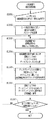
次に図10を用いて印刷装置の印刷設定を変更した際の印刷装置の処理フローを説明する。
ステップ1001において、ユーザからの印刷装置設定変更指示を受け付け、ステップ1002へ進む。ステップ1002において、ユーザ指定の指示に従い該当する設定のパラメータを変更し、ステップ1003へ進む。ステップ1003において、印刷装置内の記憶装置から印刷ジョブを読み出し、ステップ1004へ進む。ステップ1004において、印刷装置の設定情報に基づき印刷ジョブ内のベクタデータからディスプレイリストを生成し、ステップ1005へ進む。ステップ1005において、ディスプレイリスト生成時に特定サイズ以下のオブジェクトに関しては高解像度用の描画属性を適用し、ステップ1006へ進む。ステップ1006において、印刷ジョブ内のディスプレイリストを、生成したディスプレイリストに置き換えて記憶装置に保存し、ステップ1007へ進む。ステップ1007において、全ての印刷ジョブに対し処理が終わったかどうかを判定し、終わっていなければステップ1003へ戻り、ステップ1003〜1007を繰り返す。一方、ステップ1007において全ての印刷ジョブに対し処理が終わったと判定すると、本処理を終了する。
Next, a processing flow of the printing apparatus when the printing setting of the printing apparatus is changed will be described with reference to FIG.
In
次に図11を用いて本実施形態の全体フローを説明する。
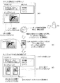
図11(a)は、図7に示した受信PDLジョブの印刷装置内記憶装置への格納処理又は図8に示したスキャンジョブの印刷装置内記憶装置への格納処理により印刷装置内に保持されているUDFの一例である。UDF内にはベクタデータに基づき生成されたディスプレイリストが保持されており、本実施形態ではイルカの絵にイメージ描画属性が適用され、”Dolphin”という文字列にテキスト描画属性が適用されていると仮定する。UDF内にはメタデータが保持されており、本印刷ジョブで使用する描画属性情報が格納されている。
Next, the overall flow of this embodiment will be described with reference to FIG.
11A is held in the printing apparatus by the storage process of the received PDL job shown in FIG. 7 in the storage apparatus in the printing apparatus or the storage process of the scan job shown in FIG. 8 in the storage apparatus in the printing apparatus. It is an example of a UDF. A display list generated based on vector data is held in the UDF. In this embodiment, an image drawing attribute is applied to a picture of a dolphin, and a text drawing attribute is applied to a character string “Dolphin”. Assume. Metadata is held in the UDF, and drawing attribute information used in this print job is stored.
図11(b)の通りにユーザが印刷装置を操作し、全ての印刷ジョブを必ず2up(物理用紙に2枚の論理ページをレイアウト)で出力する強制2up指定を設定したと仮定する。 Assume that the user operates the printing apparatus as shown in FIG. 11B, and the forced 2up designation is set so that all the print jobs are always output in 2up (two logical pages are laid out on physical paper).
強制2upが指定されると本実施形態のデータ例は、図11(c)に示す通り本来描画されるべきサイズの半分の大きさが適用されることになる。このときイルカのイメージは視認性に問題は無いが、”Dolphin”文字列は視認性の悪いサイズ(例えば4ptなど)になる。印刷装置は文字列のサイズが特定サイズ(例えば6ptなど)以下であれば文字列の視認性が悪いと判断する。従って、”Dolphin”文字列の視認性が悪くなると判断し、強制2up指定時のディスプレイリスト生成では”Dolphin”文字列に高解像度用の描画属性(例えばスモールテキスト描画属性)を適用する。 When forced 2up is designated, the data example of the present embodiment is applied with a size that is half of the size that should be originally rendered as shown in FIG. At this time, the dolphin image has no problem in visibility, but the “Dolphin” character string has a size with poor visibility (for example, 4 pt). If the size of the character string is equal to or smaller than a specific size (for example, 6 pt), the printing apparatus determines that the character string has poor visibility. Accordingly, it is determined that the visibility of the “Dolphin” character string is deteriorated, and a high-resolution drawing attribute (for example, a small text drawing attribute) is applied to the “Dolphin” character string in display list generation when forced 2up is specified.
図11(d)は、図10に示した印刷装置の設定変更処理によりディスプレイリストが再生成された印刷ジョブの一例を示す。ディスプレイリスト中の”Dolphin”文字列にスモールテキスト描画属性が適用されるとを示しているが、メタデータに関しては属性情報はテキスト情報のまま変化しない。この理由は、機器の設定が解除された際に、オリジナルの描画属性でディスプレイリストを生成できるようにするためである。 FIG. 11D shows an example of a print job in which the display list is regenerated by the setting change process of the printing apparatus shown in FIG. Although the small text drawing attribute is applied to the “Dolphin” character string in the display list, the attribute information remains unchanged as text information regarding metadata. The reason for this is to enable the display list to be generated with the original drawing attributes when the device setting is released.
(実施形態2)
図12と図13を用いて本実施形態の概要を説明する。図12は印刷装置の印刷設定を変更した際の印刷装置の処理手順を示すフローチャートであり、図中のS1201〜S1207は各処理ステップを示す。図13は本実施形態全体の流れを示す図である。
(Embodiment 2)
The outline of this embodiment will be described with reference to FIGS. FIG. 12 is a flowchart showing the processing procedure of the printing apparatus when the printing settings of the printing apparatus are changed, and S1201 to S1207 in the figure indicate each processing step. FIG. 13 is a diagram showing the overall flow of this embodiment.
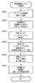
図12を用いて印刷装置の印刷設定を変更した際の印刷装置の処理フローを説明する。
ステップ1201において、ユーザからの印刷装置設定変更指示を受け付け、ステップ1202へ進む。本実施形態ではステップ1201においてユーザが印刷装置に拡張機能ボードを適用し、印刷装置に高解像度レンダリング機能を付加する設定変更を指示したと仮定する。ステップ1202において、ユーザ指定の指示に従い該当する設定のパラメータを変更し、ステップ1203へ進む。ステップ1203において、印刷装置内の記憶装置の印刷ジョブを検索し、メタデータ内に高解像度描画属性情報を有する印刷ジョブを抽出し、ステップ1204へ進む。ステップ1204において、印刷装置内の記憶装置から高解像度描画属性情報を有する印刷ジョブを読み出し、ステップ1205へ進む。ステップ1205において、印刷装置の設定情報に基づき印刷ジョブ内のベクタデータからディスプレイリストを生成し、ステップ1206へ進む。ステップ1206において、印刷ジョブ内のディスプレイリストを、生成したディスプレイリストに置き換えて記憶装置に保存し、ステップ1207へ進む。ステップ1207において、全ての高解像度描画属性情報を有する印刷ジョブに対し処理が終わったかどうかを判定し、終わっていなければステップ1204へ戻り、ステップ1204〜1207を繰り返す。一方、ステップ1207において全ての高解像度描画属性情報を有する印刷ジョブに対し処理が終わったと判定すると、本処理を終了する。
A processing flow of the printing apparatus when the printing setting of the printing apparatus is changed will be described with reference to FIG.
In
次に図13を用いて本実施形態の全体フローを説明する。
印刷装置には元々印刷ジョブ1、印刷ジョブ2、印刷ジョブ3の3つのジョブが保持されていると仮定する。印刷装置は当初600dpiの画像形成能力しか無く、各印刷ジョブのディスプレイリストは600dpi出力用のものとなっている。この状態でユーザが印刷装置に拡張機能ボードを適用し、印刷装置に1200dpiレンダリング機能を付加したとする。その際に印刷装置は、図12に示した印刷装置の印刷設定を変更した際の処理を行う。印刷装置は印刷ジョブ1〜3のメタデータ中に高解像度描画属性があるかどうかを検索する。その結果、印刷ジョブ1と印刷ジョブ3には高解像度描画属性であるスモールテキスト描画属性と高精細グラフィックス描画属性が存在することがわかる。そこで印刷装置は、印刷ジョブ1と印刷ジョブ3に対し1200dpi解像度を適用したディスプレイリスト再生成を行う。
Next, the overall flow of this embodiment will be described with reference to FIG.
Assume that the printing apparatus originally holds three jobs,
(実施形態3)
図14乃至図16を用いて本実施形態の概要を説明する。図14は印刷装置における印刷装置内記憶装置に保持されている印刷ジョブの印刷処理の処理手順を示すフローチャートであり、図中のS1401〜S1406は各処理ステップを示す。図15は印刷装置の印刷設定を変更した際の印刷装置の処理手順を示すフローチャートであり、図中のS1501〜S1507は各処理ステップを示す。図16は本実施形態全体の流れを示す図である。
(Embodiment 3)
The outline of the present embodiment will be described with reference to FIGS. FIG. 14 is a flowchart showing a processing procedure of print processing of a print job held in the storage device in the printing apparatus, and S1401 to S1406 in the figure indicate each processing step. FIG. 15 is a flowchart showing the processing procedure of the printing apparatus when the printing settings of the printing apparatus are changed, and S1501 to S1507 in the figure indicate each processing step. FIG. 16 is a diagram showing the overall flow of this embodiment.
図14を用いて印刷装置における印刷装置内記憶装置に保持されている印刷ジョブの印刷処理の流れを説明する。
ステップ1401において、ユーザからの印刷装置格納ジョブ選択を受け付け、ステップ1402へ進む。ステップ1402において、印刷装置内の記憶装置から該当する印刷ジョブを読み出し、ステップ1403へ進む。ステップ1403において、印刷ジョブ内のディスプレイリストを読み出し、ステップ1404へ進む。ステップ1404において、読み出したディスプレイリストを元に画像形成を行い、形成画像を印刷エンジンに転送し、ステップ1405へ進む。ステップ1405では、印刷エンジンにおいて、受信した印刷を紙に現像し出力し、ステップ1406へ進む。ステップ1406において、印刷装置内の記憶装置に印刷ジョブ印刷回数を記録し、本処理を終了する。
A flow of print processing of a print job held in the storage device in the printing apparatus in the printing apparatus will be described with reference to FIG.
In step 1401, the printing apparatus storage job selection from the user is accepted, and the process proceeds to step 1402. In
次に図15を用いて印刷装置の印刷設定を変更した際の印刷装置の処理フローを説明する。
ステップ1501において、ユーザからの印刷装置設定変更指示を受け付け、ステップ1502へ進む。本実施形態ではステップ1501において印刷文書に”Confidential”表示を付加するConfidentialスタンプ付加設定への変更が印刷装置に為されたと仮定する。ステップ1502において、ユーザ指定の指示に従い該当する設定のパラメータを変更し、ステップ1503へ進む。ステップ1503において、印刷装置内に保持されている各印刷ジョブの印刷回数情報を読み出し、ステップ1504へ進む。ステップ1504において、印刷装置内の記憶装置から印刷頻度の高い印刷ジョブを読み出し、ステップ1505へ進む。ステップ1505において、印刷装置の設定情報に基づき印刷ジョブ内のベクタデータからディスプレイリストを生成し、ステップ1506へ進む。ステップ1506において、印刷ジョブ内のディスプレイリストを、生成したディスプレイリストに置き換えて記憶装置に保存し、ステップ1507へ進む。ステップ1507において、全ての印刷頻度の高い印刷ジョブに対し処理が終わったかどうかを判定し、終わっていなければステップ1504へ戻り、ステップ1504〜1507を繰り返す。一方、ステップ1507において全ての印刷頻度の高い印刷ジョブに対し処理が終わったと判定すると、本処理を終了する。
Next, a processing flow of the printing apparatus when the printing setting of the printing apparatus is changed will be described with reference to FIG.
In step 1501, a printing apparatus setting change instruction from the user is accepted, and the process proceeds to step 1502. In the present embodiment, it is assumed that the printing apparatus has been changed to the Confidential stamp addition setting for adding “Confidential” display to the print document in Step 1501. In
次に図16を用いて本実施形態の全体フローを説明する。印刷装置には元々印刷ジョブ1、印刷ジョブ2、印刷ジョブ3の3つのジョブが保持されていると仮定する。又、印刷装置内に各印刷ジョブの過去1ヶ月以内のアクセス(印刷実行)回数を保持している。ユーザにより印刷装置にConfidentialスタンプ付加設定が為されるとする。印刷装置は図15に示した印刷装置の印刷設定を変更した際の印刷装置の処理を行う。印刷装置は印刷ジョブアクセス履歴を参照し、アクセス頻度の高い(例えば過去1ヶ月以内に4回以上アクセス)印刷ジョブを検索する。その結果印刷ジョブ1と印刷ジョブ2がアクセス頻度が高いことがわかる。印刷装置は印刷ジョブ1と印刷ジョブ2に対し優先的に、Confidentialスタンプを適用したディスプレイリスト再生成処理を行う。
Next, the overall flow of this embodiment will be described with reference to FIG. Assume that the printing apparatus originally holds three jobs,
<他の実施形態>
本発明は上述のように、複数の機器(たとえばホストコンピュータ、インタフェース機器、リーダ、プリンタ等)から構成されるシステムに適用しても一つの機器(たとえば複写機、ファクシミリ装置)からなる装置に適用してもよい。
<Other embodiments>
As described above, the present invention can be applied to a system composed of a plurality of devices (for example, a host computer, an interface device, a reader, a printer, etc.) but also to an apparatus composed of a single device (for example, a copying machine, a facsimile machine). May be.
また、前述した実施形態の機能を実現するように各種のデバイスを動作させるように該各種デバイスと接続された装置あるいはシステム内のコンピュータに、前記実施形態機能を実現するためのソフトウェアのプログラムコードを供給し、そのシステムあるいは装置のコンピュータ(CPUあるいはMPU)を格納されたプログラムに従って前記各種デバイスを動作させることによって実施したものも本発明の範疇に含まれる。 In addition, a program code of software for realizing the functions of the embodiment is provided in an apparatus or a computer in the system connected to the various devices so as to operate the various devices so as to realize the functions of the above-described embodiments. What is implemented by operating the various devices in accordance with a program stored in a computer (CPU or MPU) of the system or apparatus supplied is also included in the scope of the present invention.
またこの場合、前記ソフトウェアのプログラムコード自体が前述した実施形態の機能を実現することになり、そのプログラムコード自体、およびそのプログラムコードをコンピュータに供給するための手段、例えばかかるプログラムコードを格納したコンピュータ読み取り可能な記憶媒体は本発明を構成する。 In this case, the program code of the software itself realizes the functions of the above-described embodiments, and the program code itself and means for supplying the program code to the computer, for example, a computer storing the program code A readable storage medium constitutes the present invention.
かかるプログラムコードを格納する記憶媒体としては例えばフロッピーディスク、ハードディスク、光ディスク、光磁気ディスク、CD−ROM、磁気テープ、不揮発性のメモリカード、ROM等を用いることができる。 As a storage medium for storing the program code, for example, a floppy disk, a hard disk, an optical disk, a magneto-optical disk, a CD-ROM, a magnetic tape, a nonvolatile memory card, a ROM, or the like can be used.
またコンピュータが供給されたプログラムコードを実行することにより、前述の実施形態の機能が実現されるだけではなく、そのプログラムコードがコンピュータにおいて稼働しているOS(オペレーティングシステム)、あるいは他のアプリケーションソフト等と共同して前述の実施形態の機能が実現される場合にもかかるプログラムコードは本発明の実施形態に含まれることは言うまでもない。 Further, by executing the program code supplied by the computer, not only the functions of the above-described embodiments are realized, but also the OS (operating system) in which the program code is running on the computer, or other application software, etc. It goes without saying that the program code is also included in the embodiment of the present invention even when the functions of the above-described embodiment are realized in cooperation with the embodiment.
さらに供給されたプログラムコードが、コンピュータの機能拡張ボードやコンピュータに接続された機能拡張ユニットに備わるメモリに格納された後そのプログラムコードの指示に基づいてその機能拡張ボードや機能格納ユニットに備わるCPU等が実際の処理の一部または全部を行い、その処理によって前述した実施形態の機能が実現される場合も本発明に含まれることは言うまでもない。 Further, after the supplied program code is stored in a memory provided in a function expansion board of a computer or a function expansion unit connected to the computer, a CPU provided in the function expansion board or function storage unit based on an instruction of the program code However, it is needless to say that the present invention also includes a case where the function of the above-described embodiment is realized by performing part or all of the actual processing.
100 1Dカラー系MFP(印刷装置)
101 スキャナ部
102 レーザ露光部
103 感光ドラム
104 作像部
105 定着部
106 給紙/搬送部
107 転写ドラム
200 ローカルエリアネットワーク
300 印刷装置
301 スキャナ
302 プリンタエンジン
304 電話回線
305 中央演算処理装置
306 ランダムアクセスメモリ
307 リードオンリーメモリ
308 ハードディスクドライブ
309 操作部インターフェース
310 操作部
311 ネットワークインターフェース
312 モデム
313 システムバス
314 イメージバスインターフェース
315 画像バス
316 ラスターイメージプロセッサ
317 デバイスインターフェース
318 スキャナ画像処理
319 プリンタ画像処理
320 画像編集用画像処理部
330 カラーマネジメントモジュール
401 プロトコル制御部
402 ベクタデータ生成部
403 メタデータ生成部
404 PDL解析部
405 レンダラ
406 ページメモリ
407 ディスプレイリスト生成部
410 印刷制御部
420 パネル入出力制御部
430 ドキュメント記憶部
440 プリンタエンジン部
450 スキャン制御部
100 1D color MFP (printing device)
DESCRIPTION OF
Claims (5)
前記印刷設定に基づいて、前記印刷ジョブから得られる解像度非依存描画情報であるベクタデータを解釈して解像度依存描画情報であるディスプレイリストを生成する手段と、
前記ベクタデータを前記ディスプレイリストと関連付けて記憶装置に保持する保持手段と、
前記印刷設定が変更された際に、該保持されたベクタデータから該変更された設定情報に基づきディスプレイリストの再生成を行う再生成手段と、
該再生成したディスプレイリストを前記記憶装置に保持されている前記ベクタデータと関連付けて保持する手段と、
前記記憶装置に保持されているディスプレイリストを解釈して画像形成し、該形成した画像を前記記録紙へ可視像化して出力する手段と、
を備え
前記再生成手段は、
前記記憶装置に保持されているジョブのメタデータを検索し、該メタデータ内に特定の描画属性情報を含むジョブを抽出する手段と、
該抽出した特定の描画属性情報を含むジョブについて前記ディスプレイリストの再生成を行う手段と、
を備えることを特徴とする印刷装置。 In a printing apparatus that receives a print job and prints on recording paper with a predetermined print setting,
Means for interpreting vector data that is resolution-independent drawing information obtained from the print job based on the print settings and generating a display list that is resolution-dependent drawing information;
Holding means for holding the vector data in a storage device in association with the display list;
Regenerating means for regenerating a display list based on the changed setting information from the held vector data when the print setting is changed;
Means for holding the regenerated display list in association with the vector data held in the storage device;
Means for interpreting a display list held in the storage device to form an image, and visualizing and outputting the formed image to the recording paper;
With
The regeneration means includes
Means for searching for metadata of a job held in the storage device, and extracting a job including specific drawing attribute information in the metadata;
Means for regenerating the display list for a job including the extracted specific drawing attribute information;
A printing apparatus comprising:
前記印刷設定に基づいて、前記印刷ジョブから得られる解像度非依存描画情報であるベクタデータを解釈して解像度依存描画情報であるディスプレイリストを生成する手段と、
前記ベクタデータを前記ディスプレイリストと関連付けて記憶装置に保持する保持手段と、
前記印刷設定が変更された際に、該保持されたベクタデータから該変更された設定情報に基づきディスプレイリストの再生成を行う再生成手段と、
該再生成したディスプレイリストを前記記憶装置に保持されている前記ベクタデータと関連付けて保持する手段と、
前記記憶装置に保持されているディスプレイリストを解釈して画像形成し、該形成した画像を前記記録紙へ可視像化して出力する手段と、
を備え
前記再生成手段は、アクセス頻度の高いジョブに対し前記ディスプレイリストの再生成を行う
ことを特徴とする印刷装置。 In a printing apparatus that receives a print job and prints on recording paper with a predetermined print setting,
Means for interpreting vector data that is resolution-independent drawing information obtained from the print job based on the print settings and generating a display list that is resolution-dependent drawing information;
Holding means for holding the vector data in a storage device in association with the display list;
Regenerating means for regenerating a display list based on the changed setting information from the held vector data when the print setting is changed;
Means for holding the regenerated display list in association with the vector data held in the storage device;
Means for interpreting a display list held in the storage device to form an image, and visualizing and outputting the formed image to the recording paper;
The regeneration unit includes a can printing device you characterized in that to frequently accessed job regenerates the display list.
前記印刷設定に基づいて、前記印刷ジョブから得られる解像度非依存描画情報であるベクタデータを解釈して解像度依存描画情報であるディスプレイリストを生成するステップと、
前記ベクタデータを前記ディスプレイリストと関連付けて記憶装置に保持するステップと、
前記印刷設定が変更された際に、該保持されたベクタデータから該変更された設定情報に基づきディスプレイリストの再生成を行うステップと、
該再生成したディスプレイリストを前記記憶装置に保持されている前記ベクタデータと関連付けて保持するステップと、
前記記憶装置に保持されているディスプレイリストを解釈して画像形成し、該形成した画像を前記記録紙へ可視像化して出力するステップと、
を含み、
前記再生成ステップは、
前記記憶装置に保持されているジョブのメタデータを検索し、該メタデータ内に特定の描画属性情報を含むジョブを抽出するステップと、
該抽出した特定の描画属性情報を含むジョブについて前記ディスプレイリストの再生成を行うステップと
を含むことを特徴とする制御方法。 In a control method of a printing apparatus that receives a print job and prints on a recording sheet with a predetermined print setting,
Interpreting vector data that is resolution-independent drawing information obtained from the print job based on the print settings to generate a display list that is resolution-dependent drawing information;
Holding the vector data in a storage device in association with the display list;
Regenerating the display list based on the changed setting information from the held vector data when the print setting is changed;
Holding the regenerated display list in association with the vector data held in the storage device;
Interpreting a display list held in the storage device to form an image, and visualizing and outputting the formed image to the recording paper; and
Only including,
The regeneration step includes:
Searching for metadata of a job held in the storage device, and extracting a job including specific drawing attribute information in the metadata;
And regenerating the display list for a job including the extracted specific drawing attribute information .
前記印刷設定に基づいて、前記印刷ジョブから得られる解像度非依存描画情報であるベクタデータを解釈して解像度依存描画情報であるディスプレイリストを生成するステップと、
前記ベクタデータを前記ディスプレイリストと関連付けて記憶装置に保持するステップと、
前記印刷設定が変更された際に、該保持されたベクタデータから該変更された設定情報に基づきディスプレイリストの再生成を行うステップと、
該再生成したディスプレイリストを前記記憶装置に保持されている前記ベクタデータと関連付けて保持するステップと、
前記記憶装置に保持されているディスプレイリストを解釈して画像形成し、該形成した画像を前記記録紙へ可視像化して出力するステップと、
を含み、
前記再生成ステップにおいて、アクセス頻度の高いジョブに対し前記ディスプレイリストの再生成を行う
ことを特徴とする制御方法。 In a control method of a printing apparatus that receives a print job and prints on a recording sheet with a predetermined print setting,
Interpreting vector data that is resolution-independent drawing information obtained from the print job based on the print settings to generate a display list that is resolution-dependent drawing information;
Holding the vector data in a storage device in association with the display list;
Regenerating the display list based on the changed setting information from the held vector data when the print setting is changed;
Holding the regenerated display list in association with the vector data held in the storage device;
Interpreting a display list held in the storage device to form an image, and visualizing and outputting the formed image to the recording paper; and
Including
Wherein in the re-generation step, that control how to, characterized in that to frequently accessed job regenerates the display list.
Priority Applications (2)
| Application Number | Priority Date | Filing Date | Title |
|---|---|---|---|
| JP2008130636A JP5288879B2 (en) | 2008-05-19 | 2008-05-19 | Printing apparatus, control method therefor, program, and computer-readable storage medium |
| US12/433,903 US8259330B2 (en) | 2008-05-19 | 2009-05-01 | Output efficiency of printer forming image by interpreting PDL and performing output by using print engine |
Applications Claiming Priority (1)
| Application Number | Priority Date | Filing Date | Title |
|---|---|---|---|
| JP2008130636A JP5288879B2 (en) | 2008-05-19 | 2008-05-19 | Printing apparatus, control method therefor, program, and computer-readable storage medium |
Publications (3)
| Publication Number | Publication Date |
|---|---|
| JP2009274419A JP2009274419A (en) | 2009-11-26 |
| JP2009274419A5 JP2009274419A5 (en) | 2011-06-30 |
| JP5288879B2 true JP5288879B2 (en) | 2013-09-11 |
Family
ID=41315873
Family Applications (1)
| Application Number | Title | Priority Date | Filing Date |
|---|---|---|---|
| JP2008130636A Expired - Fee Related JP5288879B2 (en) | 2008-05-19 | 2008-05-19 | Printing apparatus, control method therefor, program, and computer-readable storage medium |
Country Status (2)
| Country | Link |
|---|---|
| US (1) | US8259330B2 (en) |
| JP (1) | JP5288879B2 (en) |
Families Citing this family (7)
| Publication number | Priority date | Publication date | Assignee | Title |
|---|---|---|---|---|
| JP5084543B2 (en) * | 2008-02-12 | 2012-11-28 | キヤノン株式会社 | Image processing apparatus and image processing method |
| JP5528121B2 (en) * | 2010-01-05 | 2014-06-25 | キヤノン株式会社 | Image processing apparatus, image processing method, and program |
| JP5406237B2 (en) * | 2011-03-31 | 2014-02-05 | 富士フイルム株式会社 | Calibration image display apparatus, method and program |
| US9501858B2 (en) * | 2012-05-28 | 2016-11-22 | Mitsubishi Electric Corporation | Display device and computer |
| EP2955908B1 (en) * | 2014-06-12 | 2022-07-27 | Hewlett-Packard Development Company, L.P. | Image forming apparatus |
| US10348937B2 (en) * | 2017-02-22 | 2019-07-09 | Biscom Inc. | High-definition facsimile routing |
| US11245801B2 (en) * | 2020-03-31 | 2022-02-08 | Kyocera Document Solutions Inc. | Image forming apparatus and image forming method capable of changing guidance screen from terminal |
Family Cites Families (10)
| Publication number | Priority date | Publication date | Assignee | Title |
|---|---|---|---|---|
| JP2000272178A (en) * | 1999-03-26 | 2000-10-03 | Minolta Co Ltd | Image forming apparatus, system, and method, and image output device |
| JP2004288013A (en) | 2003-03-24 | 2004-10-14 | Canon Inc | Print control method |
| US8014013B2 (en) * | 2004-06-24 | 2011-09-06 | Sharp Laboratories Of America, Inc. | Systems and methods for segmenting pages and changing settings for graphical elements in printing |
| JP4514213B2 (en) * | 2005-03-31 | 2010-07-28 | キヤノン株式会社 | Image processing apparatus and control method thereof |
| JP2006327016A (en) * | 2005-05-26 | 2006-12-07 | Canon Inc | Image processing apparatus, image processing method, storing medium storing computer-readable program, and program |
| JP2007025969A (en) * | 2005-07-14 | 2007-02-01 | Canon Inc | Processing and device and storage medium for use of meta data in dlc compilation |
| JP4347286B2 (en) * | 2005-10-18 | 2009-10-21 | 京セラミタ株式会社 | Image forming apparatus |
| JP2007156613A (en) * | 2005-12-01 | 2007-06-21 | Canon Inc | Drawing controller, drawing control method, storage medium and program |
| JP2007182064A (en) * | 2005-12-08 | 2007-07-19 | Canon Inc | Image processing apparatus and image processing method |
| JP4164518B2 (en) * | 2006-06-05 | 2008-10-15 | キヤノン株式会社 | Image processing apparatus, control method therefor, and program |
-
2008
- 2008-05-19 JP JP2008130636A patent/JP5288879B2/en not_active Expired - Fee Related
-
2009
- 2009-05-01 US US12/433,903 patent/US8259330B2/en not_active Expired - Fee Related
Also Published As
| Publication number | Publication date |
|---|---|
| US8259330B2 (en) | 2012-09-04 |
| US20090284787A1 (en) | 2009-11-19 |
| JP2009274419A (en) | 2009-11-26 |
Similar Documents
| Publication | Publication Date | Title |
|---|---|---|
| JP5038229B2 (en) | Image processing apparatus, image processing method, image processing program, and recording medium for recording the same | |
| JP5043715B2 (en) | Image processing device | |
| JP4928373B2 (en) | Image processing apparatus, image processing method, and image processing program | |
| JP5058904B2 (en) | Image processing apparatus, image processing method, and program thereof | |
| JP5288879B2 (en) | Printing apparatus, control method therefor, program, and computer-readable storage medium | |
| US20080180707A1 (en) | Image processing apparatus, image processing system, and image processing method | |
| JP5188201B2 (en) | Image processing apparatus, control method therefor, program, and storage medium | |
| US8185504B2 (en) | Image processing apparatus and image processing method | |
| JP5006764B2 (en) | Image processing apparatus, image processing method, program, and storage medium | |
| JP5258313B2 (en) | Image processing system, image processing method, and program | |
| JP2009282709A (en) | Image processing apparatus and method of controlling the same, program, and storage medium | |
| JP2009165025A (en) | Image processing system, control method of image processing system, and control program | |
| JP5022986B2 (en) | Image processing apparatus, image processing method, and program for executing image processing method | |
| US8259313B2 (en) | Image processing apparatus, method, and computer-readable medium storing the program thereof | |
| US8179560B2 (en) | Image processing apparatus and image processing method | |
| US20090279780A1 (en) | Image processing apparatus, method of controlling the same, and program | |
| JP5036636B2 (en) | Image processing apparatus, method, and program | |
| JP5110945B2 (en) | Image processing apparatus, control method therefor, and program | |
| JP5265042B2 (en) | Image processing apparatus, image processing method, image processing program, and recording medium for recording the same | |
| JP2010081549A (en) | Image processing apparatus | |
| JP2009188677A (en) | Image processing apparatus and its processing method | |
| JP2014138990A (en) | Printing device, printing method and program | |
| JP2010079850A (en) | Electronic document conversion system | |
| JP2010145889A (en) | Image processor and control method, program and storing medium of the same |
Legal Events
| Date | Code | Title | Description |
|---|---|---|---|
| RD02 | Notification of acceptance of power of attorney |
Free format text: JAPANESE INTERMEDIATE CODE: A7422 Effective date: 20101106 |
|
| A521 | Request for written amendment filed |
Free format text: JAPANESE INTERMEDIATE CODE: A523 Effective date: 20110517 |
|
| A621 | Written request for application examination |
Free format text: JAPANESE INTERMEDIATE CODE: A621 Effective date: 20110517 |
|
| A131 | Notification of reasons for refusal |
Free format text: JAPANESE INTERMEDIATE CODE: A131 Effective date: 20130226 |
|
| A521 | Request for written amendment filed |
Free format text: JAPANESE INTERMEDIATE CODE: A523 Effective date: 20130405 |
|
| TRDD | Decision of grant or rejection written | ||
| A01 | Written decision to grant a patent or to grant a registration (utility model) |
Free format text: JAPANESE INTERMEDIATE CODE: A01 Effective date: 20130507 |
|
| A61 | First payment of annual fees (during grant procedure) |
Free format text: JAPANESE INTERMEDIATE CODE: A61 Effective date: 20130604 |
|
| LAPS | Cancellation because of no payment of annual fees |