JP5281660B2 - Shader-based extension for declarative presentation framework - Google Patents
Shader-based extension for declarative presentation framework Download PDFInfo
- Publication number
- JP5281660B2 JP5281660B2 JP2010549691A JP2010549691A JP5281660B2 JP 5281660 B2 JP5281660 B2 JP 5281660B2 JP 2010549691 A JP2010549691 A JP 2010549691A JP 2010549691 A JP2010549691 A JP 2010549691A JP 5281660 B2 JP5281660 B2 JP 5281660B2
- Authority
- JP
- Japan
- Prior art keywords
- shader
- declarative
- effects
- input
- programming model
- Prior art date
- Legal status (The legal status is an assumption and is not a legal conclusion. Google has not performed a legal analysis and makes no representation as to the accuracy of the status listed.)
- Active
Links
- 230000000694 effects Effects 0.000 claims description 106
- 238000000034 method Methods 0.000 claims description 50
- 238000012545 processing Methods 0.000 claims description 17
- 101000857680 Xenopus laevis Runt-related transcription factor 1 Proteins 0.000 claims description 2
- 230000008859 change Effects 0.000 claims description 2
- 238000010586 diagram Methods 0.000 description 18
- 238000009877 rendering Methods 0.000 description 15
- 230000009466 transformation Effects 0.000 description 13
- 238000012360 testing method Methods 0.000 description 12
- 230000006870 function Effects 0.000 description 11
- 230000008569 process Effects 0.000 description 5
- 230000006399 behavior Effects 0.000 description 4
- 230000008901 benefit Effects 0.000 description 4
- 238000013507 mapping Methods 0.000 description 4
- 239000003086 colorant Substances 0.000 description 3
- 239000013598 vector Substances 0.000 description 3
- 230000000007 visual effect Effects 0.000 description 3
- 230000008878 coupling Effects 0.000 description 2
- 238000010168 coupling process Methods 0.000 description 2
- 238000005859 coupling reaction Methods 0.000 description 2
- 230000001419 dependent effect Effects 0.000 description 2
- 230000003287 optical effect Effects 0.000 description 2
- 230000009471 action Effects 0.000 description 1
- 238000003491 array Methods 0.000 description 1
- 238000004891 communication Methods 0.000 description 1
- 239000000470 constituent Substances 0.000 description 1
- 238000005516 engineering process Methods 0.000 description 1
- 238000007667 floating Methods 0.000 description 1
- 239000012634 fragment Substances 0.000 description 1
- 230000003993 interaction Effects 0.000 description 1
- 230000007246 mechanism Effects 0.000 description 1
- 238000012986 modification Methods 0.000 description 1
- 230000004048 modification Effects 0.000 description 1
- -1 points Substances 0.000 description 1
- 238000000926 separation method Methods 0.000 description 1
- 230000008093 supporting effect Effects 0.000 description 1
- 238000000844 transformation Methods 0.000 description 1
Images


Classifications
-
- G—PHYSICS
- G06—COMPUTING; CALCULATING OR COUNTING
- G06T—IMAGE DATA PROCESSING OR GENERATION, IN GENERAL
- G06T15/00—3D [Three Dimensional] image rendering
- G06T15/005—General purpose rendering architectures
Landscapes
- Engineering & Computer Science (AREA)
- Computer Graphics (AREA)
- Physics & Mathematics (AREA)
- General Physics & Mathematics (AREA)
- Theoretical Computer Science (AREA)
- Image Generation (AREA)
- Image Processing (AREA)
Description
本発明は、宣言型プレゼンテーション・フレームワークのためのシェーダーベースの拡張に関する。 The present invention relates to a shader-based extension for a declarative presentation framework.
[0001]グラフィック処理装置(GPU)はコンピューターのための専用のグラフィック・レンダリング装置である。今日のGPUはコンピューター・グラフィックの操作及び表示において効率的であり、それらの並列構造は、一連の複雑なアルゴリズムのための最も汎用の中央処理装置よりもそれらを有効なものにする。CPUはまた複数のプロセッサー・コアを有してもよい。GPUのように、マルチコアCPUは、複数の動作を並行して実行することができる。 [0001] A graphics processing unit (GPU) is a dedicated graphics rendering device for a computer. Today's GPUs are efficient at manipulating and displaying computer graphics, and their parallel structure makes them more efficient than the most general-purpose central processors for a series of complex algorithms. The CPU may also have multiple processor cores. Like the GPU, the multi-core CPU can execute a plurality of operations in parallel.
[0002]今日、ソフトウェアを書くソフトウェア開発者は、自身が書くソフトウェア・アプリケーションにおいてこの処理能力を利用したいと考えている。例えば、多くのグラフィック効果又はマルチメディアを利用するデスクトップベース又はウェブベースのアプリケーションなどの、大量の処理リソースを必要とするアプリケーションにおいて、コンピューター中に存在するGPU又はマルチコア・プロセッサーの能力を利用することは有用である。しかし、多くのプラットフォームはGPU又はマルチコア・プロセッサーのリソースを利用し得るが、末端の開発者は、通常、今日多くのコンピューターに含まれる余分な処理能力を利用することができるプラットフォーム上で動作するアプリケーションを容易に構築することができない。 [0002] Today, software developers who write software want to take advantage of this processing power in the software applications they write. Taking advantage of the power of GPUs or multi-core processors that exist in computers in applications that require a large amount of processing resources, such as desktop-based or web-based applications that utilize many graphic effects or multimedia Useful. However, while many platforms can take advantage of GPU or multi-core processor resources, end developers typically run applications on platforms that can take advantage of the extra processing power included in many computers today. Cannot be easily built.
[0003]シェーダーを宣言的に制御するための様々な技術及び技法が開示される。宣言型のプログラミング・モデルは、宣言型プレゼンテーション・フレームワークにおけるシェーダーのインスタンス化を制御する宣言文(declarative statements)を使用することを可能にする。宣言的に指定されたシェーダーは、ソフトウェア・アプリケーションのためにグラフィック効果をレンダリングする(ソフトウェア・アプリケーションにグラフィック効果を与える)ためのプレゼンテーション・フレームワークによって後にインスタンス化される(インスタンスを作成される、instantiated)。1つの実施例において、宣言型のプログラミング・モデルは、単一パス動作(single pass operation)中に実行されるべきシェーダーを制御しカプセル化する単一パスシェーダーとして使用することができる。別の実施例において、複数パス動作(multiple pass operation)中に実行されるべき1組のシェーダーを制御しカプセル化する複数パス効果として宣言型のプログラミング・モデルを利用するための方法が記載される。カスタム方法(カスタム・メソッド、custom method)が複数パス効果について呼び出される。カスタム方法は複数パス効果クラスから導かれたものである。カスタム方法は、カスタム方法が複数パス効果の動作を制御することを可能にするためのシェーダー・コンテキスト及び制御情報にカスタム方法がアクセスすることを可能にする、コンテキストを備えている。 [0003] Various techniques and techniques for declaratively controlling a shader are disclosed. The declarative programming model allows the use of declarative statements that control the instantiation of shaders in a declarative presentation framework. A declaratively specified shader is later instantiated (instantiated, instantiated) by a presentation framework for rendering graphic effects for software applications (giving graphic effects to software applications) ). In one embodiment, the declarative programming model can be used as a single pass shader that controls and encapsulates the shader to be executed during a single pass operation. In another embodiment, a method is described for utilizing a declarative programming model as a multi-pass effect that controls and encapsulates a set of shaders to be executed during multiple pass operations. . A custom method is called for multi-pass effects. Custom methods are derived from multi-pass effect classes. The custom method has a context that allows the custom method to access shader context and control information to allow the custom method to control the behavior of the multi-pass effect.
[0004]この概要は詳細な説明においてさらに以下に述べる概念の選択を単純化された形式で紹介するために提供された。この概要は、特許請求される主題の主な特徴又は本質的な特徴を識別するようには意図されず、特許請求される主題の範囲を決定する際に助けとして使用されるようにも意図されない。 [0004] This summary is provided to introduce a selection of concepts in a simplified form that are further described below in the detailed description. This summary is not intended to identify key features or essential features of the claimed subject matter, nor is it intended to be used as an aid in determining the scope of the claimed subject matter. .
[0019]本明細書において技術及び技法は宣言型のプログラミング・モデルを備えたシェーダーを使用するための技術及び技法として一般的なコンテキストにおいて述べられてもよいが、技術及び技法はまた、これらに加えて他の目的に役立つ。1つの実施例において、本明細書に記載される1つ以上の技術は、MICROSOFT(登録商標).NETフレームワークなどのソフトウェア開発プラットフォーム内の機能、又は開発者がソフトウェア・アプリケーションを開発し及び/又はカスタマイズすることを可能にするためのプラットフォームを提供する他の種類のプログラム又はサービスからの機能として実施することができる。 [0019] Although techniques and techniques herein may be described in a general context as techniques and techniques for using shaders with a declarative programming model, the techniques and techniques may also be described herein. In addition it serves other purposes. In one embodiment, one or more techniques described herein are MICROSOFT®. Implemented as a function within a software development platform, such as the NET framework, or from other types of programs or services that provide a platform to allow developers to develop and / or customize software applications can do.
[0020]、宣言型プレゼンテーション・フレームワーク上で実行される宣言型のプログラミング・モデル108を使用してシェーダー106の動作を制御するためのシステム100の線図が図1に示される。本明細書において使用される「宣言文」なる語及び「宣言的に」なる語は、関連する宣言型のフレームワークの基本的な実施に対してその実行を委ねる、テキストベースのマークアップ又は命令コード(imperative code)を含むことを意図する。宣言型言語の例は、少数の限定的でない例を挙げると、XAML及びXMLを含む。本明細書において使用される「宣言型のプログラミング・モデル」なる語は、関連する宣言型のフレームワークによって処理されるべき効果をインスタンス化し使用するために、開発者、別のユーザー又はプログラムが当該プログラミング・モデルによって宣言文を設定する、プログラミング・モデルを含むことを意図する。本明細書において使用される「宣言型プレゼンテーション・フレームワーク」なる語は、宣言型のプログラミング・モデルを使用して宣言文によって開発者、別のユーザー又はプログラムによって提供される、より抽象的な記述とのインタラクションを表示し可能にするシステムを含むことを意図する。宣言型プレゼンテーション・フレームワークの制限的でない1つの例は、MICROSOFT Windows(登録商標) Presentation Foundation(すなわち、WPF)であり、これは、(バージョン3.0で始まる)MICROSOFT.NETフレームワークのグラフィカルなサブシステム機能である。WPFは、アプリケーションを構築するための一貫したプログラミング・モデルを提供し、ユーザー・インターフェース・ロジックとビジネスロジックとの間の明確な分離を提供する。宣言型プレゼンテーション・フレームワークの制限的でない別の例はMICROSOFT Silverlightである。
[0020] A diagram of a
[0021]本明細書において使用される「シェーダー(shader)」なる語は、主としてグラフィカルなレンダリング効果を行うためにグラフィックのリソースによって使用される1組のコンピューター命令を含むことを意図する。システム100に利用することができる、画素シェーダー、頂点(vertex)シェーダー及び/又は形状(配置、幾何学、geometry)シェーダーなどの異なる種類のシェーダーが存在する。頂点シェーダーは一連の頂点に影響を及ぼし、したがって、位置、色及びテクスチャ座標のような頂点特性を変更することができる。頂点シェーダーによって計算された頂点は、通常、形状シェーダーに渡される。形状シェーダーは、メッシュから頂点を追加及び削除することができる。形状シェーダーは、手続きに従って形状(配置)を生成するため又は既存のメッシュに容積測定の(volumetric)詳細を加えるために使用することができ、これは、通常は、演算処理装置上で処理するにはコストがかかりすぎる。画素シェーダーはフラグメントシェーダーとしてより一般に知られており、頂点シェーダー及び形状シェーダーによって生成された多角形がラスターライズされる場合、個々の画素の明度(color value)を計算する。画素シェーダーは、通常、シーン照明(scene lighting)、並びにバンプ・マッピング及び色調整などの関連する効果のために使用される。
[0021] The term "shader" as used herein is intended to include a set of computer instructions that are used primarily by graphic resources to perform graphical rendering effects. There are different types of shaders that can be utilized in the
[0022]1つ以上の演算処理装置104上でシェーダー106が実行される。演算処理装置104の少数の制限的でない例はグラフィック処理装置(GPU)又はマルチコア・プロセッサーを含み得る。シェーダー106が1つ以上の演算処理装置104上で実行される場合、「シェーダー・プロセッサー」なる語は演算処理装置104上でのシェーダーの実行を指すのに使用される。以前に述べたように、シェーダー106は所与のソフトウェア・アプリケーションに対して効果を与える(レンダリングする)責務を有する。宣言型のプログラミング・モデル108は、開発者又は他のユーザーがユーザー宣言型の(user-declared)シェーダー・カスタマイゼーション110を提供することを可能にする。図2−13のフロー及びコードの例においてここでさらに詳細に述べられるように、シェーダー・カスタマイゼーション110は、ユーザーがシェーダー106のインスタンス化及び/又は動作を制御することを可能にする。
[0022] A
[0023]図2は、宣言型プレゼンテーション・フレームワークにおけるシェーダーのインスタンス化及び動作を制御する宣言文が使用されることを可能にする、1つの実施例についての宣言型のプログラミング・モデル150の線図である。宣言型のプログラミング・モデル150は、シェーダーの制御のために宣言的に指定することができる様々な機能をサポートする。1つの実施例において、宣言型のプログラミング・モデル150は、単一パス動作中に実行されるべきシェーダーを制御しカプセル化する単一パスシェーダーとして使用することができる。別の実施例において、宣言型のプログラミング・モデル150は、複数パス動作中に実行されるべき1組のシェーダーを制御しカプセル化する複数パス効果として使用することができる。複数パス効果は、本明細書における複数パス効果164についての議論及び図12の議論においてより詳細に述べられる。
[0023] FIG. 2 illustrates a line of a
[0024]宣言型のプログラミング・モデル150を使用して、ブラシは、シェーダーへの入力152として指定することができる。本明細書において使用される「ブラシ」なる語は、形状を満たすために適用されると、どの画素位置にどの色を配置するかを決定することができるオブジェクトを表すことを意図する。より抽象的には、ブラシは2D空間から色へのマッピング機能を表す。例示的なブラシは、単純なラスター画像、線形且つ放射状の勾配(グラディエント)、ライブビデオのソース、他のベクトル・グラフィック・レンダリングからのソースなどを含む。ブラシはその上画素シェーダーに対する入力としての役割を果たし、シェーダーによって処理されるべき「サンプラー」としてシェーダー自体に対して提示することができる。シェーダーへの入力としてブラシを利用することについてのさらなる詳細は図4−5についての議論において提供される。
[0024] Using the
[0025]宣言型のプログラミング・モデル150は、潜在的な入力がシェーダー・プロセッサーに提供されることを可能にして、グラフィック効果がその一次入力などの入力154をどこで得るかを制御する。本明細書において使用される「潜在的な入力(implicit input)」なる語は、「効果/シェーダーが適用されているユーザー・インターフェース要素をラスタライズすることに起因する、画素ベースのビットマップ」を含むよう意図する。したがって、例えば、効果がボタンに適用される場合、「潜在的な入力」はそのボタンを表すビットマップである。潜在的な入力の一例は、図5においてより詳細に述べられる。
[0025] The
[0026]シェーダー入力156に対する特性結合(property binding)はまた、宣言型のプログラミング・モデル150によりサポートされる。本明細書において使用される「特性結合」なる語は、データ結合を行うかそうでなければ柔軟な制御を行うときにアニメーション実行するために参照することができるオブジェクト指向のクラス定義の宣言型の特性を含むことを意図する。。いくつかの実施例において、そのような特性は依存特性(Dependency Properties)として知られている。本明細書において使用される「シェーダー入力」なる語は、レジスターインデックスを介してシェーダーにとって利用可能になる「シェーダー定数」及び「シェーダーサンプラー」の両方を含むことを意図する。本明細書において使用される「シェーダー定数」なる語は、シェーダープログラムの実行の全体にわたって一定のままである、シェーダープログラムに提供される値を含むことを意図する。シェーダー定数についての少数の制限的でない例は、浮動小数点値、色、点、ベクトル、行列などを含む。本明細書において使用される「シェーダーサンプラー」なる語は、特定の座標点においてシェーダープログラム内でサンプリングすることができるシェーダープログラムに提供される多次元アレイを含むことを意図する。少数の制限的でない例は2Dビットマップ及び3Dテクスチャー・ボリュームを含んでもよい。言いかえれば、宣言型のプログラミング・モデル150は、依存特性がシェーダー入力と宣言的に接続されることを可能にする。シェーダー入力156に対する特性結合は、図6及び7においてより詳細に述べられる。1つの実施例において、シェーダー入力に対する特性結合をサポートすることによって、それらの依存特性は、シェーダーの実施についてさらに知る必要のあるシェーダーを(特性宣言を含むより高いレベルのオブジェクトを介して)使用している開発者なしにシェーダーに渡すことができる。
[0026] Property binding to the shader input 156 is also supported by the
[0027]宣言型のプログラミング・モデル150はまた、効果ブラシがシェーダーの実行からのブラシとして作用するように定義される(158)ことを可能にする。本明細書において使用される「効果ブラシ」なる語は、シェーダー又は一連のシェーダーの実行による2D空間から色へのその機能を定義する(上に定義されるような)あらゆる「ブラシ」を含むことを意図する。効果ブラシは、一般に、他のブラシと同様の方法で使用することができる。1組の明示的な入力を仮定すると、効果ブラシは、ブラシが適用されている目標を満たすために色を生成する。この機能を利用して、システムはシェーダーを実行するために予め何もレンダリングする必要はない。言いかえれば、効果ブラシ機能は、シェーダーがユーザー・インターフェース要素のブラシとして実行することを可能にする。効果ブラシは図8及び9においてより詳細に述べられる。
[0027] The
[0028]宣言型のプログラミング・モデル150によってサポートされる別の機能は、効果が入力をどのように変えるかをモデル化するための、一般的な変換160を使用するヒット・テスト及び座標空間変換である。本明細書において使用される「ヒット・テスト」なる語は、シェーダーが適用された後に座標空間における特定の点の位置を求める要求の処理を含むことを意図する。本明細書において使用される「座標空間変換」なる語は、シェーダーベースの効果を経る必要性及びシェーダーが潜在的に画素を変換するのと同じ方法で座標を変換するコードを有することを含む、変換階層に沿った任意のマッピングを含むことを意図する。インタラクトされるときにマウス位置又は入力ポインター位置を効果が適用される変換の逆を介して変換する必要があるように、ある効果はそのコンテンツをあちこち移動させることができる。一般的な変換160機能を使用するヒット・テストは、ある効果が入力をモデル化されるようにシフトする方法を可能にする。例えば、効果がボタンを「回転させる(swirl)」場合、入力ポインターは、それが回転されたボタンの表現の上にあり、且つ、ボタンがもともと存在していたがもはやそこに存在していない空間の上にある場合でないときに、ボタンの「上に」あるものとして登録するべきである。ヒット・テストは図10及び11においてより詳細に述べられる。
[0028] Another feature supported by the
[0029]宣言型のプログラミング・モデル150はまた、画素自体162の上でシェーダーを実行することによりヒット・テストをサポートする。この機能により、シェーダーは、実際の画素座標を得るために特定の画素上で実行することができる。これは、上述のようなヒット・テストに必要な座標空間マッピングを行うための1つの可能な実施例を表す。これは図10においてより詳細に述べられる。
[0029] The
[0030]複数パス効果164はまた宣言型のプログラミング・モデル150によりサポートされる。複数パス効果により、複数のレベルの効果があり得、一度に1つのシェーダー上で起こる1組の動作として具体化される。開発者は、宣言型のプログラミング・モデル150を使用して、シェーダーの複数のパスを制御し拡張することができる。複数パス効果164は、図12においてより詳細に述べられる。
[0030] The
[0031]ここで図3−13に移ると、シェーダー動作を制御するためのシステムの1つ以上の実施例を実施するための段階がより詳細に記述される。いくつかの実施例において、図3−13のプロセスは、(図14の)計算装置500の動作論理において少なくとも部分的に実施される。 [0031] Turning now to FIGS. 3-13, steps for implementing one or more embodiments of a system for controlling shader operation will be described in greater detail. In some embodiments, the process of FIGS. 3-13 is at least partially implemented in the operational logic of computing device 500 (of FIG. 14).
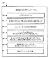
[0032]図3は、宣言型のプログラミング・モデルを使用してシェーダーベースの効果を定義することに関与する段階を示す1つの実施例についての処理フロー図200である。宣言的に参照されたシェーダーベースの効果は、ソフトウェア・アプリケーションにグラフィック効果を与える(レンダリングする)ための宣言型プレゼンテーション・フレームワークによってプログラムで例示化される(instantiated)(段階202)。シェーダーの少数の制限的でない例は、画素シェーダー、頂点シェーダー及び/又は形状シェーダーを含んでもよい。宣言文はソフトウェア・アプリケーションについてアクセスされる(段階204)。言いかえれば、シェーダーのためのグラフィック効果カスタマイゼーションを含む宣言文は、宣言文を含む1つ以上のファイルから取り出される。1つの実施例において、それらがシェーダーによって必要とされるとき、宣言文はシェーダーの動作の全体にわたってアクセスされる(段階204)。グラフィック効果カスタマイゼーションによりソフトウェア・アプリケーションに対してシェーダーがグラフィック効果を与えることを可能にするために、宣言文はシェーダー・プロセッサーへ送られる(段階206)。言いかえれば、宣言文はシェーダー・プロセッサーへ送られ、宣言型の方法で開発者、他のもの又はプログラムのユーザーによって指定された所望のグラフィック効果カスタマイゼーションを実行するためにシェーダーによって使用される。1つの実施例において、宣言文は、シェーダーが実行されるGPUやマルチコア・プロセッサーなどの演算処理装置(の能力)をグラフィック効果カスタマイゼーションが利用することを可能にする。 [0032] FIG. 3 is a process flow diagram 200 for one embodiment showing the stages involved in defining shader-based effects using a declarative programming model. Declaratively referenced shader-based effects are programmatically instantiated (step 202) by a declarative presentation framework for rendering (rendering) graphic effects to software applications. A few non-limiting examples of shaders may include pixel shaders, vertex shaders, and / or shape shaders. The declaration statement is accessed for the software application (step 204). In other words, declaration statements that include graphic effect customizations for shaders are retrieved from one or more files that contain declaration statements. In one embodiment, declaration statements are accessed throughout the operation of the shader as they are needed by the shader (step 204). A declaration statement is sent to the shader processor to allow the shader to provide a graphic effect to the software application through graphic effects customization (step 206). In other words, the declaration statement is sent to the shader processor and used by the shader to perform the desired graphic effects customization specified by the developer, others or the user of the program in a declarative manner. In one embodiment, the declaration statement allows the graphics effects customization to utilize a processing unit such as a GPU or multi-core processor on which the shader is executed.
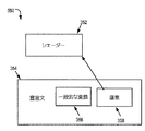
[0033]図4は、シェーダー222への入力として使用されている1つ以上の宣言文224を使用して定義されたブラシ226を示す1つの実施例についての線図220である。ブラシは、放射状の勾配、ビットマップ画像、動画、ベクトル・グラフィックなどの特徴が、(いくつかの既存のシェーダーがサポートする正当なビットマップとは対照的な)シェーダーへの入力として役立つことを可能にする。ブラシの概念をより詳細に示すためのコードの例は図5に示される。
[0033] FIG. 4 is a diagram 220 for one embodiment showing a
[0034]図5は、シェーダーへの二次的な入力としてブラシの使用を示し、シェーダーへの潜在的な入力の使用を示す、1つの実施例についてのある例示的なソース・コード250である。示された例において、myButtonと呼ばれるボタンが宣言的に指定されている。当該ボタンは、テクスチャー減算効果(texture subtraction effect)の最下段特性(底特性)についての入力としてブラシ254を含むボタン効果により宣言されたものである。テクスチャー減算効果の頂点特性は、効果が適用されている要素のビットマップ・レンダリング−この場合、myButtonのレンダリング−を表す潜在的な入力特性252を含む。最終的な結果は、当該ボタンが、今は、それから減算されたブラシ254からの画像を備えた元のボタンのレンダリングのように見えるということである。
[0034] FIG. 5 is an
[0035]図6は、シェーダー定数及び/又はサンプラーであり得る、1つ以上のシェーダー入力284への1つ以上の依存特性288の結合を示す1つの実施例の線図280である。以前に述べたように、シェーダー入力はレジスターインデックスによってシェーダーにとって利用可能になる。依存特性は、所与のシェーダー282のシェーダー入力284に結合するために宣言文286を使用して指定することができる。1つの実施例において、依存特性をシェーダー入力と接続することによって、依存特性は、定義することができ、シェーダーの詳細についてユーザーが心配する必要なくシェーダーに渡すことができる。宣言型の方法によるシェーダー入力への(より具体的には、シェーダー定数への)依存特性の結合の例は図7に示される。図7に示される例示的なソース・コードにおいて、シェーダー定数に対する2つの依存性(304及び306)は宣言的に指定される。それらの依存性(304及び306)は、シェーダー定数308及び310などのシェーダー302の実際の登録に結合される。1つの実施例において、当該結合はコールバックの使用を通じて遂行され、これは、依存特性がいつ変更されようとも、効果、及びしたがってシェーダーが実行される次回のための新たな値でシェーダー入力を更新するよう宣言型のフレームワークに命じるコールバック関数が呼び出されることを意味する。
[0035] FIG. 6 is a diagram 280 of one example illustrating the coupling of one or
[0036]図8は、効果ブラシを定義する際のシェーダーの使用を示す1つの実施例についての線図320である。図2に述べられるように、効果ブラシ326は、シェーダー322の実行からのブラシとして作用するために宣言文324を使用して定義することができる。1組の明示的な入力を考慮すると、効果ブラシ326は、ブラシが適用されているその目標を満たすために色を生成する。効果ブラシ機能は、シェーダー322がユーザー・インターフェース要素のブラシとして実行されることを可能にする。効果ブラシ326を宣言的に指定するための例示的なソース・コード330は図9に示される。図9に示される例において、効果ブラシはカスタム効果334により宣言的に指定される(332)。示された例におけるカスタム結果334は、矩形に対してフラクタル・フィル(fractal fill)を生成する。この例において、効果ブラシは、効果(Effect)種類である単一のパラメーター、Effectとともに使用される。更に、MandelbrotEffectは、シェーダー入力として基本的なシェーダーに渡される3つの依存特性を備えたカスタムShaderEffectである。その後、効果の出力は矩形を満たすために使用される。
[0036] FIG. 8 is a diagram 320 for one example illustrating the use of shaders in defining an effect brush. As described in FIG. 2, the
[0037]ここで図10に移ると、シェーダー352による一般的な変換356を使用すること及び/又は特定の画素358においてシェーダー352を実行することにより、ヒット・テスト及び座標空間変換の性能を示す、1つの実施例についての線図が示される。以前に述べたように、ヒット・テストは、シェーダーが適用された後に座標空間において指定された点の位置を求める要求の処理を意味する。一般的な変換356は宣言文354を使用して指定することができ、ヒット・テスト及び座標空間変換がモデル化されることを可能にする。一般的な変換の例は図11の例示的なソース・コード380に示される。代替的に又はさらに、ヒット・テストは特定の画素358上でシェーダー352を実行することにより行うことができる。
[0037] Turning now to FIG. 10, the performance of hit testing and coordinate space transformation is shown by using a
[0038]図12は、複数パス動作中に実行されるべき1組のシェーダーを制御しカプセル化する複数パス効果を示す1つの実施例についての処理フロー図440である。本明細書において使用される「複数パス効果」なる語は、所望のレンダリングを達成するために1つより多くのシェーダーを複数回潜在的に呼び出す効果を含むことを意図する。本明細書において使用される「複数パス動作」なる語は、複数のパス及び複数のシェーダーの実行を制御するコードを含むことを意図する。カスタム方法は複数パス効果に対して呼び出される(段階442)。1つの実施例において、カスタム方法は複数パス効果クラスから導かれる。1つの実施例において、カスタム方法は、それが適用シェーダー(例えば、ApplyShaders)の方法を無効にするように定義される。適用シェーダーの方法は、カスタム方法における複数パス効果の各々のパスについてそれぞれのシェーダーをプログラムによって選択するためのロジックを含む。 [0038] FIG. 12 is a process flow diagram 440 for one embodiment illustrating the multi-pass effect of controlling and encapsulating a set of shaders to be executed during multi-pass operation. The term “multi-pass effect” as used herein is intended to include effects that potentially call more than one shader multiple times to achieve the desired rendering. As used herein, the term “multi-pass operation” is intended to include code that controls the execution of multiple passes and multiple shaders. The custom method is invoked for multi-pass effects (stage 442). In one embodiment, the custom method is derived from a multiple pass effect class. In one embodiment, a custom method is defined such that it overrides the method of applied shaders (eg, ApplyShaders). The applied shader method includes logic to programmatically select the respective shader for each pass of the multi-pass effect in the custom method.
[0039]カスタム方法は、当該カスタム方法が複数パス効果の動作を制御することを可能にする(段階446)ために、当該カスタム方法がシェーダー・コンテキスト及び制御情報にアクセスすることを可能にする(段階444)コンテキストを備えている。言いかえれば、カスタム方法はシステムによって呼び出され、シェーダーインデックス、現在の地球規模(グローバル・スケール)、シェーダー定数、シェーダーサンプラー及び/又はシェーダーを選択し実行するための能力のような関連情報のアクセス及び制御を可能にする「コンテキスト」を備えている。この機構によって、カスタム方法における複数パス効果の開発者は、複数パス効果レンダリングを制御することができる。 [0039] The custom method allows the custom method to access shader context and control information to allow the custom method to control the behavior of the multi-pass effect (stage 446). Step 444) Provide context. In other words, the custom method is invoked by the system to access relevant information such as shader index, current global scale, shader constant, shader sampler and / or ability to select and execute shaders and It has a “context” that allows control. This mechanism allows multi-pass effect developers in custom methods to control multi-pass effect rendering.
[0040]1つの実施例において、複数パス効果機能の使用によって、複数シェーダー効果ベースクラス(base class)の特定のサブクラスのユーザーは、宣言型のグラフィック又はユーザー・インターフェース表現にその効果を含めるために、当該効果を宣言的に指定することのみを必要とする。 [0040] In one embodiment, by using the multi-pass effect feature, a user of a particular subclass of a multi-shader effect base class can include the effect in a declarative graphic or user interface representation. It is only necessary to specify the effect declaratively.
[0041]1つの実施例において、グラフィック効果カスタマイゼーションは、所与の複数パス効果におけるすべてのパスについて構成スレッド上で呼び出される。構成スレッドは図13においてより詳細に述べられ、それはここで次に議論される。 [0041] In one embodiment, graphic effects customization is invoked on the configuration thread for all passes in a given multi-pass effect. The configuration thread is described in more detail in FIG. 13, which will now be discussed next.
[0042]図13は、ユーザー・インターフェース・スレッドから構成スレッドまでの制御の流れを示す1つの実施例についての線図480である。本明細書において使用される「ユーザー・インターフェース・スレッド」なる語は、アプリケーションのユーザー・インターフェース要素(ボタン、テキストボックス、リスト)が応答する実行の主要なスレッドを含むことを意図する。本明細書において使用される「構成スレッド」なる語は、ディスプレイのレンダリングを制御するユーザー・インターフェース・スレッドとは異なるスレッドを含むことを意図する。構成スレッドに対する動作はUIスレッドに対する動作によってブロックされない。 [0042] FIG. 13 is a diagram 480 for one example illustrating the flow of control from a user interface thread to a configuration thread. As used herein, the term “user interface thread” is intended to include the main thread of execution to which the user interface elements (buttons, text boxes, lists) of the application respond. As used herein, the term “configuration thread” is intended to include a different thread than the user interface thread that controls the rendering of the display. Operations on the constituent thread are not blocked by operations on the UI thread.
[0043]図13に戻ると、フローの制御はユーザー・インターフェース・スレッドと構成スレッドとの間で示される。ユーザー・インターフェース・スレッドにおいては、宣言文が解析され、効果が構築され(段階482)、次に、効果を含む視覚的なツリーが構築される(段階484)。構成スレッドにおいては、構成側の視覚的なツリーに相当するものが構築される(段階486)。ユーザー・インターフェース・スレッドに戻ると、効果依存特性は結合され評価される(段階488)。ユーザー・インターフェース・スレッドに存在する間、ユーザー・インターフェース・スレッド・レンダリング・ループは、アニメーションを評価し、構成レンダリングを呼び出す(段階490)。その後、構成スレッドはフレームをレンダリングし(段階492)、効果により視覚的なツリーノード上でヒットをレンダリングする(段階494)。1つの実施例において、次に起こることは、レンダリングされる効果の種類に基づいて異なる(段階496)。マルチパス効果の場合には、効果の実行を制御するために、ApplyShaders方法が構成スレッドから呼び出される。単一パス効果の場合には、構成スレッドが如何なるユーザー・コードも呼び出すことなく効果を単に実行するのに十分な情報が、構成スレッド上に既に存在する。 [0043] Returning to FIG. 13, control of the flow is shown between the user interface thread and the configuration thread. In the user interface thread, the declaration statement is parsed, effects are built (stage 482), and then a visual tree containing the effects is built (stage 484). In the composition thread, what corresponds to the visual tree on the composition side is constructed (step 486). Returning to the user interface thread, the effect dependent properties are combined and evaluated (stage 488). While present in the user interface thread, the user interface thread rendering loop evaluates the animation and invokes the configuration rendering (stage 490). The composition thread then renders the frame (stage 492) and renders the hit on the visual tree node with the effect (stage 494). In one embodiment, what happens next varies based on the type of effect being rendered (stage 496). In the case of a multi-pass effect, the ApplyShaders method is called from the configuration thread to control the execution of the effect. In the case of a single pass effect, there is already enough information on the configuration thread for the configuration thread to simply execute the effect without invoking any user code.
[0044]図14に示されるように、システムの1つ以上の部分を実施するのに使用するための例示的なコンピューター・システムは、計算装置500などの計算装置を含む。そのほとんどの基本構成において、計算装置500は、通常、少なくとも1つの演算処理装置502及びメモリー504を含む。計算装置の正確な構成及び種類によって、メモリー504は、(RAMなどの)揮発性のものであってもよいし、(ROM、フラッシュ・メモリーなどのように)不揮発性のものであってもよいし、又はこれら2つのある組合せであってもよい。この大部分の基本構成は破線506によって図14に示される。
[0044] As shown in FIG. 14, an exemplary computer system for use in implementing one or more portions of the system includes a computing device, such as
[0045]さらに、装置500はまた、追加の特徴/機能を有してもよい。例えば、装置500はまた、磁気もしくは光のディスク又はテープを含むがこれらに限定されない、(取り外し可能及び/又は取り外し不能な)追加の記憶装置を含んでもよい。そのような追加の記憶装置は、取り外し可能な記憶装置508及び取り外し不能な記憶装置510によって図14に示される。コンピューター記憶媒体は、コンピューター読み取り可能な命令、データ構造、プログラムモジュール又は他のデータなどの情報の記憶のための任意の方法又は技術において実施される、揮発性及び不揮発性、取り外し可能及び取り外し不能な媒体を含む。メモリー504、取り外し可能な記憶装置508及び取り外し不能な記憶装置510は、すべて、コンピューター記憶媒体の例である。コンピューター記憶媒体は、RAM、ROM、EEPROM、フラッシュ・メモリーもしくは他のメモリー技術、CD−ROM、ディジタル・バーサタイル・ディスク(DVD)もしくは他の光学記憶装置、磁気カセット、磁気テープ、磁気ディスク記憶装置もしくは他の磁気記憶装置、又は所望の情報を格納するために使用することができ且つ装置500によってアクセスできる任意の他の媒体を含むがこれらに限定されない。如何なるそのようなコンピューター記憶媒体も装置500の一部であり得る。
[0045] Furthermore, the
[0046]計算装置500は、計算装置500が他のコンピューター/アプリケーション515と通信することを可能にする1つ以上の通信接続514を含む。装置500はまた、キーボード、マウス、ペン、音声入力装置、タッチ入力装置などの入力装置512を有してもよい。ディスプレイ、スピーカー、プリンターなどの出力装置511も含まれてもよい。これらの装置は当技術分野において周知であり、ここで詳細に議論する必要はない。
[0046] The
[0047]主題は構造的特徴及び/又は方法論の作用に特有の言語で説明されたが、添付の特許請求の範囲において規定される主題が上述の特定の特徴又は作用に必ずしも限定されないことが理解されるべきである。そのようなものではなく、上述の特定の特徴及び作用は、請求項を実行する例示的な形式として開示されたものである。本明細書に記載されるような実施例及び/又は以下の特許請求の範囲によって記載されるような実施例の趣旨にあるすべての均等物、変更及び修正は保護されることが望まれる。 [0047] Although the subject matter has been described in language specific to structural features and / or methodological actions, it is understood that the subject matter defined in the appended claims is not necessarily limited to the specific features or acts described above. It should be. Rather, the specific features and acts described above are disclosed as example forms of implementing the claims. All equivalents, changes, and modifications within the spirit of the embodiments as described herein and / or as described by the following claims are desired to be protected.
[0048]例えば、コンピューター・ソフトウェア技術における当業者であれば、本明細書において記載された例が、実施例において表現されたようなものより少ない又は追加のオプション又は機能を含むように、1つ以上のコンピューター上で異なったように組織化することができることを認識するであろう。 [0048] For example, one of ordinary skill in the computer software arts will appreciate that one example described herein includes fewer or additional options or features than those expressed in the examples. It will be appreciated that the above computers can be organized differently.
Claims (17)
宣言型プレゼンテーション・フレームワークにおいてシェーダーのインスタンス化及び動作を制御する宣言型言語の宣言文が使用されることを可能にする宣言型のプログラミング・モデルを備え、前記シェーダーはグラフィック処理装置上で実行するように動作可能であり、前記宣言型のプログラミング・モデルは、ソフトウェア・アプリケーションにおけるグラフィック効果のために前記グラフィック処理装置を利用するため、前記ソフトウェア・アプリケーションが前記宣言型のプログラミング・モデルを使用することを可能にし、前記宣言型のプログラミング・モデルはブラシが前記シェーダーへの入力として使用されることを可能にするように動作可能であるシステム。 A system for controlling the operation of a shader,
A declarative programming model that allows declarative language declaration statements to be used to control the instantiation and behavior of shaders in a declarative presentation framework, the shaders executing on a graphics processing unit The software application uses the declarative programming model because the declarative programming model utilizes the graphic processing device for graphic effects in the software application. And the declarative programming model is operable to allow a brush to be used as an input to the shader .
ソフトウェア・アプリケーションに対してグラフィック効果をレンダリングするために、宣言的に指定されたシェーダーベースの効果をプログラムによって例示化するステップと、
シェーダーについてグラフィック効果カスタマイゼーションを含む、前記ソフトウェア・アプリケーションのための宣言文にアクセスするステップであって、前記宣言文は宣言型言語で書かれ、前記宣言型言語は拡張マークアップ言語又は拡張アプリケーションマークアップ言語を含む、ステップと、
前記グラフィック効果カスタマイゼーションを備えた前記ソフトウェア・アプリケーションについて前記シェーダーがグラフィック効果をレンダリングすることを可能にするために、シェーダー・プロセッサーへ前記宣言文を送信するステップであって、前記宣言文はブラシが前記シェーダーへの二次的な入力として使用されることを可能にし、潜在的な入力が前記シェーダーへの入力として使用されることを可能にし、潜在的な入力は、効果が適用されているユーザー・インターフェース要素をラスタライズすることによって生じる画素ベースのビットマップを含む、ステップと
を備える方法。 A method for defining shader-based effects and using said shader-based effects in a declarative programming model, comprising:
Programmatically instantiating declaratively specified shader-based effects to render graphic effects for software applications;
Accessing a declaration statement for the software application, including graphic effects customization for a shader, wherein the declaration statement is written in a declarative language, the declarative language being an extended markup language or an extended application markup Including language, steps,
Sending the declaration statement to a shader processor to enable the shader to render a graphic effect for the software application with the graphic effects customization , the declaration statement including a brush Allows the input to be used as a secondary input to the shader, allows the potential input to be used as an input to the shader, and Comprising a pixel-based bitmap resulting from rasterizing the interface elements .
拡張マークアップ言語又は拡張アプリケーションマークアップ言語を含む宣言型言語で書かれた宣言文を使用して、複数パス効果クラスから導出される、複数パス効果のためのカスタム方法を呼び出すステップと、
前記カスタム方法が前記複数パス効果の動作を制御することを可能にするために、前記カスタム方法がシェーダー・コンテキスト及び制御情報にアクセスすることを可能にするコンテキストを前記カスタム方法に提供するステップと
を備える方法。 Using a declarative programming model as a multi-pass effect to control and encapsulate a set of shaders to be executed during multi-pass operation,
Invoking a custom method for multi-pass effects, derived from a multi-pass effect class, using a declaration statement written in a declarative language including an extended markup language or an extended application markup language;
Providing the custom method with a context that allows the custom method to access shader context and control information to allow the custom method to control the operation of the multi-pass effect. How to prepare.
Applications Claiming Priority (3)
| Application Number | Priority Date | Filing Date | Title |
|---|---|---|---|
| US12/041,951 US8345045B2 (en) | 2008-03-04 | 2008-03-04 | Shader-based extensions for a declarative presentation framework |
| US12/041,951 | 2008-03-04 | ||
| PCT/US2009/032611 WO2009111119A1 (en) | 2008-03-04 | 2009-01-30 | Shader-based extensions for a declarative presentation framework |
Publications (3)
| Publication Number | Publication Date |
|---|---|
| JP2011517803A JP2011517803A (en) | 2011-06-16 |
| JP2011517803A5 JP2011517803A5 (en) | 2012-02-16 |
| JP5281660B2 true JP5281660B2 (en) | 2013-09-04 |
Family
ID=41053123
Family Applications (1)
| Application Number | Title | Priority Date | Filing Date |
|---|---|---|---|
| JP2010549691A Active JP5281660B2 (en) | 2008-03-04 | 2009-01-30 | Shader-based extension for declarative presentation framework |
Country Status (7)
| Country | Link |
|---|---|
| US (1) | US8345045B2 (en) |
| EP (1) | EP2260465A4 (en) |
| JP (1) | JP5281660B2 (en) |
| KR (1) | KR101618381B1 (en) |
| BR (1) | BRPI0907861A2 (en) |
| MX (1) | MX2010009741A (en) |
| WO (1) | WO2009111119A1 (en) |
Families Citing this family (9)
| Publication number | Priority date | Publication date | Assignee | Title |
|---|---|---|---|---|
| US8563314B2 (en) * | 2007-09-27 | 2013-10-22 | Sangamo Biosciences, Inc. | Methods and compositions for modulating PD1 |
| US20110298816A1 (en) * | 2010-06-03 | 2011-12-08 | Microsoft Corporation | Updating graphical display content |
| US9153193B2 (en) * | 2011-09-09 | 2015-10-06 | Microsoft Technology Licensing, Llc | Primitive rendering using a single primitive type |
| US8872838B2 (en) * | 2011-09-09 | 2014-10-28 | Microsoft Corporation | Primitive composition |
| US9021437B2 (en) * | 2012-07-13 | 2015-04-28 | Microsoft Technology Licensing, Llc | Declarative style rules for default touch behaviors |
| US20140191980A1 (en) * | 2013-01-04 | 2014-07-10 | Qualcomm Mems Technologies, Inc. | System for reuse of touch panel and controller by a secondary display |
| US20140354658A1 (en) * | 2013-05-31 | 2014-12-04 | Microsoft Corporation | Shader Function Linking Graph |
| US9875568B2 (en) * | 2013-06-06 | 2018-01-23 | Nvidia Corporation | Graphics effect data structure and method of use thereof |
| US9733823B2 (en) | 2015-04-01 | 2017-08-15 | Microsoft Technology Licensing, Llc | View activation via hit testing in an asynchronous windowing system |
Family Cites Families (20)
| Publication number | Priority date | Publication date | Assignee | Title |
|---|---|---|---|---|
| CN1119047A (en) | 1993-08-24 | 1996-03-20 | 塔里根特公司 | Object oriented shading |
| US7548238B2 (en) * | 1997-07-02 | 2009-06-16 | Nvidia Corporation | Computer graphics shader systems and methods |
| US7009605B2 (en) * | 2002-03-20 | 2006-03-07 | Nvidia Corporation | System, method and computer program product for generating a shader program |
| US7523406B2 (en) | 2003-07-22 | 2009-04-21 | Autodesk Inc. | Dynamic parameter interface |
| US7212206B2 (en) * | 2003-08-20 | 2007-05-01 | Sony Computer Entertainment Inc. | Method and apparatus for self shadowing and self interreflection light capture |
| US7570267B2 (en) * | 2004-05-03 | 2009-08-04 | Microsoft Corporation | Systems and methods for providing an enhanced graphics pipeline |
| US20050243085A1 (en) * | 2004-05-03 | 2005-11-03 | Microsoft Corporation | Model 3D construction application program interface |
| US7958498B1 (en) * | 2004-07-02 | 2011-06-07 | Nvidia Corporation | Methods and systems for processing a geometry shader program developed in a high-level shading language |
| CN101091175B (en) | 2004-09-16 | 2012-03-14 | 辉达公司 | Load balancing |
| US20060071933A1 (en) * | 2004-10-06 | 2006-04-06 | Sony Computer Entertainment Inc. | Application binary interface for multi-pass shaders |
| US7733347B2 (en) | 2004-11-05 | 2010-06-08 | Microsoft Corporation | Automated construction of shader programs |
| US7376894B2 (en) * | 2004-11-18 | 2008-05-20 | Microsoft Corporation | Vector path merging into gradient elements |
| WO2006094199A2 (en) | 2005-03-03 | 2006-09-08 | Pixar | Hybrid hardware-accelerated relighting system for computer cinematography |
| CA2613541A1 (en) * | 2005-07-01 | 2007-01-11 | Mental Images Gmbh | Computer graphics shader systems and methods |
| US7817151B2 (en) | 2005-10-18 | 2010-10-19 | Via Technologies, Inc. | Hardware corrected software vertex shader |
| JP4718993B2 (en) * | 2005-12-26 | 2011-07-06 | 株式会社東芝 | Drawing apparatus and drawing method |
| JP2007193655A (en) | 2006-01-20 | 2007-08-02 | Sharp Corp | Electronic document data processor, electronic document data processing method and program for functioning computer as electronic document data processor |
| US8261270B2 (en) | 2006-06-20 | 2012-09-04 | Google Inc. | Systems and methods for generating reference results using a parallel-processing computer system |
| US7952588B2 (en) | 2006-08-03 | 2011-05-31 | Qualcomm Incorporated | Graphics processing unit with extended vertex cache |
| US8203558B2 (en) * | 2008-01-28 | 2012-06-19 | Apple Inc. | Dynamic shader generation |
-
2008
- 2008-03-04 US US12/041,951 patent/US8345045B2/en active Active
-
2009
- 2009-01-30 KR KR1020107019524A patent/KR101618381B1/en active IP Right Grant
- 2009-01-30 BR BRPI0907861-4A patent/BRPI0907861A2/en not_active Application Discontinuation
- 2009-01-30 JP JP2010549691A patent/JP5281660B2/en active Active
- 2009-01-30 EP EP09716566.6A patent/EP2260465A4/en not_active Withdrawn
- 2009-01-30 MX MX2010009741A patent/MX2010009741A/en not_active Application Discontinuation
- 2009-01-30 WO PCT/US2009/032611 patent/WO2009111119A1/en active Application Filing
Also Published As
| Publication number | Publication date |
|---|---|
| JP2011517803A (en) | 2011-06-16 |
| BRPI0907861A2 (en) | 2015-07-21 |
| EP2260465A4 (en) | 2017-01-25 |
| KR101618381B1 (en) | 2016-05-18 |
| EP2260465A1 (en) | 2010-12-15 |
| US20090225079A1 (en) | 2009-09-10 |
| MX2010009741A (en) | 2010-09-28 |
| US8345045B2 (en) | 2013-01-01 |
| KR20100123853A (en) | 2010-11-25 |
| WO2009111119A1 (en) | 2009-09-11 |
Similar Documents
| Publication | Publication Date | Title |
|---|---|---|
| JP5281660B2 (en) | Shader-based extension for declarative presentation framework | |
| US10026147B1 (en) | Graphics scenegraph rendering for web applications using native code modules | |
| JP4290477B2 (en) | Markup language and object model for vector graphics | |
| US8294723B2 (en) | Hardware-accelerated graphics for web applications using native code modules | |
| US20120174079A1 (en) | Systems and methods for simulating a mobile device application | |
| US9710950B2 (en) | Extensible sprite sheet generation mechanism for declarative data formats and animation sequence formats | |
| EP3137985B1 (en) | Method and system to create a rendering pipeline | |
| Cozzi et al. | OpenGL insights | |
| US20140313197A1 (en) | Method for Displaying a 3D Scene Graph on a Screen | |
| WO2017058541A1 (en) | System and method for using ubershader variants without preprocessing macros | |
| US20130080879A1 (en) | Methods and apparatus providing document elements formatting | |
| US20150348315A1 (en) | Dynamic Lighting Effects For Textures Without Normal Maps | |
| US9052924B2 (en) | Light-weight managed composite control hosting | |
| Martz | OpenGL distilled | |
| US9508108B1 (en) | Hardware-accelerated graphics for user interface elements in web applications | |
| US11244419B2 (en) | Method and apparatus for hardware accelerated graphics rendering in bridge APIs | |
| CN111324381B (en) | Development system, development method, development apparatus, computer device, and storage medium | |
| US8203567B2 (en) | Graphics processing method and apparatus implementing window system | |
| Stenning | Direct3D Rendering Cookbook | |
| US9069905B2 (en) | Tool-based testing for composited systems | |
| Baruah et al. | Up and Running with WebGL | |
| Bossard | High-performance graphics in Racket with DirectX | |
| Sharan et al. | Introduction to JavaFX | |
| CN116503529A (en) | Rendering, 3D picture control method, electronic device, and computer-readable storage medium | |
| Imrýšek | WPF Style GUI Library for MonoGame Framework |
Legal Events
| Date | Code | Title | Description |
|---|---|---|---|
| A521 | Request for written amendment filed |
Free format text: JAPANESE INTERMEDIATE CODE: A523 Effective date: 20111221 |
|
| A621 | Written request for application examination |
Free format text: JAPANESE INTERMEDIATE CODE: A621 Effective date: 20111221 |
|
| A977 | Report on retrieval |
Free format text: JAPANESE INTERMEDIATE CODE: A971007 Effective date: 20130116 |
|
| A131 | Notification of reasons for refusal |
Free format text: JAPANESE INTERMEDIATE CODE: A131 Effective date: 20130122 |
|
| A521 | Request for written amendment filed |
Free format text: JAPANESE INTERMEDIATE CODE: A523 Effective date: 20130321 |
|
| TRDD | Decision of grant or rejection written | ||
| A01 | Written decision to grant a patent or to grant a registration (utility model) |
Free format text: JAPANESE INTERMEDIATE CODE: A01 Effective date: 20130425 |
|
| A61 | First payment of annual fees (during grant procedure) |
Free format text: JAPANESE INTERMEDIATE CODE: A61 Effective date: 20130524 |
|
| R150 | Certificate of patent or registration of utility model |
Free format text: JAPANESE INTERMEDIATE CODE: R150 Ref document number: 5281660 Country of ref document: JP Free format text: JAPANESE INTERMEDIATE CODE: R150 |
|
| S111 | Request for change of ownership or part of ownership |
Free format text: JAPANESE INTERMEDIATE CODE: R313113 |
|
| R350 | Written notification of registration of transfer |
Free format text: JAPANESE INTERMEDIATE CODE: R350 |
|
| R250 | Receipt of annual fees |
Free format text: JAPANESE INTERMEDIATE CODE: R250 |
|
| R250 | Receipt of annual fees |
Free format text: JAPANESE INTERMEDIATE CODE: R250 |
|
| R250 | Receipt of annual fees |
Free format text: JAPANESE INTERMEDIATE CODE: R250 |
|
| R250 | Receipt of annual fees |
Free format text: JAPANESE INTERMEDIATE CODE: R250 |
|
| R250 | Receipt of annual fees |
Free format text: JAPANESE INTERMEDIATE CODE: R250 |
|
| R250 | Receipt of annual fees |
Free format text: JAPANESE INTERMEDIATE CODE: R250 |
|
| R250 | Receipt of annual fees |
Free format text: JAPANESE INTERMEDIATE CODE: R250 |
|
| R250 | Receipt of annual fees |
Free format text: JAPANESE INTERMEDIATE CODE: R250 |
|
| R250 | Receipt of annual fees |
Free format text: JAPANESE INTERMEDIATE CODE: R250 |