JP5271997B2 - Intake air temperature sensor - Google Patents
Intake air temperature sensor Download PDFInfo
- Publication number
- JP5271997B2 JP5271997B2 JP2010291534A JP2010291534A JP5271997B2 JP 5271997 B2 JP5271997 B2 JP 5271997B2 JP 2010291534 A JP2010291534 A JP 2010291534A JP 2010291534 A JP2010291534 A JP 2010291534A JP 5271997 B2 JP5271997 B2 JP 5271997B2
- Authority
- JP
- Japan
- Prior art keywords
- intake air
- air temperature
- temperature sensor
- intake
- detection element
- Prior art date
- Legal status (The legal status is an assumption and is not a legal conclusion. Google has not performed a legal analysis and makes no representation as to the accuracy of the status listed.)
- Active
Links
- 238000001514 detection method Methods 0.000 claims description 38
- 229910052751 metal Inorganic materials 0.000 claims description 16
- 239000002184 metal Substances 0.000 claims description 16
- 239000000919 ceramic Substances 0.000 claims description 7
- 239000000463 material Substances 0.000 claims description 6
- 229920005989 resin Polymers 0.000 claims description 4
- 239000011347 resin Substances 0.000 claims description 4
- 239000004734 Polyphenylene sulfide Substances 0.000 claims description 2
- -1 polybutylene terephthalate Polymers 0.000 claims description 2
- 229920001707 polybutylene terephthalate Polymers 0.000 claims description 2
- 229920000069 polyphenylene sulfide Polymers 0.000 claims description 2
- 230000017525 heat dissipation Effects 0.000 claims 1
- 229910000679 solder Inorganic materials 0.000 description 11
- PCHJSUWPFVWCPO-UHFFFAOYSA-N gold Chemical compound [Au] PCHJSUWPFVWCPO-UHFFFAOYSA-N 0.000 description 8
- 238000010438 heat treatment Methods 0.000 description 7
- 239000000758 substrate Substances 0.000 description 7
- 230000004048 modification Effects 0.000 description 4
- 238000012986 modification Methods 0.000 description 4
- 230000005855 radiation Effects 0.000 description 4
- 230000000694 effects Effects 0.000 description 3
- 239000011521 glass Substances 0.000 description 3
- 230000004044 response Effects 0.000 description 3
- 230000008859 change Effects 0.000 description 2
- 239000011248 coating agent Substances 0.000 description 2
- 238000000576 coating method Methods 0.000 description 2
- 238000010586 diagram Methods 0.000 description 2
- BASFCYQUMIYNBI-UHFFFAOYSA-N platinum Chemical compound [Pt] BASFCYQUMIYNBI-UHFFFAOYSA-N 0.000 description 2
- 230000035939 shock Effects 0.000 description 2
- 239000000853 adhesive Substances 0.000 description 1
- 230000001070 adhesive effect Effects 0.000 description 1
- 230000008878 coupling Effects 0.000 description 1
- 238000010168 coupling process Methods 0.000 description 1
- 238000005859 coupling reaction Methods 0.000 description 1
- 239000003822 epoxy resin Substances 0.000 description 1
- 239000000446 fuel Substances 0.000 description 1
- 239000010931 gold Substances 0.000 description 1
- 229910052737 gold Inorganic materials 0.000 description 1
- 238000005259 measurement Methods 0.000 description 1
- 238000000034 method Methods 0.000 description 1
- 229910052697 platinum Inorganic materials 0.000 description 1
- 229920003217 poly(methylsilsesquioxane) Polymers 0.000 description 1
- 229920000647 polyepoxide Polymers 0.000 description 1
- 230000002250 progressing effect Effects 0.000 description 1
- 230000009467 reduction Effects 0.000 description 1
- 238000011144 upstream manufacturing Methods 0.000 description 1
Images


Classifications
-
- G—PHYSICS
- G01—MEASURING; TESTING
- G01K—MEASURING TEMPERATURE; MEASURING QUANTITY OF HEAT; THERMALLY-SENSITIVE ELEMENTS NOT OTHERWISE PROVIDED FOR
- G01K13/00—Thermometers specially adapted for specific purposes
- G01K13/02—Thermometers specially adapted for specific purposes for measuring temperature of moving fluids or granular materials capable of flow
-
- G—PHYSICS
- G01—MEASURING; TESTING
- G01F—MEASURING VOLUME, VOLUME FLOW, MASS FLOW OR LIQUID LEVEL; METERING BY VOLUME
- G01F1/00—Measuring the volume flow or mass flow of fluid or fluent solid material wherein the fluid passes through a meter in a continuous flow
- G01F1/68—Measuring the volume flow or mass flow of fluid or fluent solid material wherein the fluid passes through a meter in a continuous flow by using thermal effects
- G01F1/684—Structural arrangements; Mounting of elements, e.g. in relation to fluid flow
- G01F1/6842—Structural arrangements; Mounting of elements, e.g. in relation to fluid flow with means for influencing the fluid flow
-
- G—PHYSICS
- G01—MEASURING; TESTING
- G01F—MEASURING VOLUME, VOLUME FLOW, MASS FLOW OR LIQUID LEVEL; METERING BY VOLUME
- G01F15/00—Details of, or accessories for, apparatus of groups G01F1/00 - G01F13/00 insofar as such details or appliances are not adapted to particular types of such apparatus
- G01F15/18—Supports or connecting means for meters
- G01F15/185—Connecting means, e.g. bypass conduits
-
- G—PHYSICS
- G01—MEASURING; TESTING
- G01F—MEASURING VOLUME, VOLUME FLOW, MASS FLOW OR LIQUID LEVEL; METERING BY VOLUME
- G01F5/00—Measuring a proportion of the volume flow
-
- G—PHYSICS
- G01—MEASURING; TESTING
- G01K—MEASURING TEMPERATURE; MEASURING QUANTITY OF HEAT; THERMALLY-SENSITIVE ELEMENTS NOT OTHERWISE PROVIDED FOR
- G01K1/00—Details of thermometers not specially adapted for particular types of thermometer
- G01K1/16—Special arrangements for conducting heat from the object to the sensitive element
-
- G—PHYSICS
- G01—MEASURING; TESTING
- G01K—MEASURING TEMPERATURE; MEASURING QUANTITY OF HEAT; THERMALLY-SENSITIVE ELEMENTS NOT OTHERWISE PROVIDED FOR
- G01K2205/00—Application of thermometers in motors, e.g. of a vehicle
- G01K2205/02—Application of thermometers in motors, e.g. of a vehicle for measuring inlet gas temperature
Landscapes
- Physics & Mathematics (AREA)
- General Physics & Mathematics (AREA)
- Fluid Mechanics (AREA)
- Measuring Volume Flow (AREA)
- Measuring Temperature Or Quantity Of Heat (AREA)
Description
本発明は吸気温度センサに係り、特に低流量での測定精度が高く、且つ、応答性の良い吸気温度センサに関する。 The present invention relates to an intake air temperature sensor, and more particularly to an intake air temperature sensor with high measurement accuracy at a low flow rate and good response.
吸気管内の吸気温度を検出する従来の吸気温度センサには特許文献1に記載された流量測定装置や特許文献2に記載された熱式空気流量計などがある。
Conventional intake air temperature sensors for detecting the intake air temperature in the intake pipe include a flow rate measuring device described in Patent Document 1 and a thermal air flow meter described in
特許文献1では金属ターミナルを利用して吸気温度検出素子を吸気流に直接露出するように配置している。 In Patent Document 1, a metal terminal is used so that the intake air temperature detecting element is directly exposed to the intake air flow.
しかしながら、吸気流量が低流量になった場合に対する配慮が欠けていた。最近の自動車エンジンは低燃費化のためにアイドリングの低回転数化を志向している。このため、吸気流量の低流量化が進んでいる。吸気流量が低流量になると吸気温度検出素子の表面から吸気流への熱抵抗が急激に高くなる。この結果、取付け部からの熱や回路の自己発熱が金属ターミナルを伝わって吸気温度検出素子の温度を変化させる。このため、吸気温度検出素子の温度と吸気温度の間に差が生じ、正確に吸気温度を検出できなくなってしまう。また、吸気温度検出素子の表面から吸気流への熱抵抗が高くなると、吸気温度検出素子自体の熱容量によって生じる熱時定数が数十秒に達し、吸気温度の検出遅れが大きくなってしまう。 However, there was a lack of consideration for the case where the intake flow rate became low. Recent automobile engines aim to reduce idling speed in order to reduce fuel consumption. For this reason, the reduction of the intake flow rate is progressing. When the intake air flow rate becomes low, the thermal resistance from the surface of the intake air temperature detecting element to the intake air flow increases rapidly. As a result, heat from the mounting portion and self-heating of the circuit are transmitted through the metal terminal to change the temperature of the intake air temperature detecting element. For this reason, a difference occurs between the temperature of the intake air temperature detecting element and the intake air temperature, and the intake air temperature cannot be accurately detected. Further, when the thermal resistance from the surface of the intake air temperature detection element to the intake air flow increases, the thermal time constant generated by the heat capacity of the intake air temperature detection element itself reaches several tens of seconds, and the detection delay of the intake air temperature increases.
特許文献2では副通路内に吸気温度検出素子を配置し、流量検出素子と吸気温度検出素子を同一回路基板に配置している。しかし、副通路構造体は取付け部からの熱や回路の自己発熱によって吸気流とは異なる温度になる。特に低流量ではこの傾向は強くなる。このため、副通路構造体からの熱影響を受けて副通路内の空気の温度は変化し、被測定空気流とは異なる温度となってしまう。また、副通路内部に吸気温度検出素子が配置されているため、吸気温度検出素子は副通路内の空気流の温度を検出してしまう。これより、吸気温度検出素子の出力に誤差が生じてしまう。
In
更に、副通路構造体の温度変化は筐体の熱時定数の影響を受けるので副通路構造体の温度が安定するまでには数十秒から数分の時間を必要としてしまう。このため、上記技術では吸気温度が変化してから数十秒から数分間、吸気温度センサの出力は不正確になってしまう。また、回路基板をガラス・エポキシ樹脂の様な熱抵抗の高い材料を採用している。このため、駆動回路からの自己発熱の影響は低減できるが、空気流への熱抵抗の低減に関しては配慮が欠けており、低流量での吸気温度検出素子の熱時定数は数十秒に達し、吸気温度の検出遅れを大きくする。 Furthermore, since the temperature change of the sub-passage structure is affected by the thermal time constant of the casing, it takes several tens of seconds to several minutes before the temperature of the sub-passage structure is stabilized. For this reason, in the above technique, the output of the intake air temperature sensor becomes inaccurate for several tens of seconds to several minutes after the intake air temperature changes. The circuit board is made of a material having high thermal resistance such as glass / epoxy resin. For this reason, the influence of self-heating from the drive circuit can be reduced, but there is a lack of consideration for reducing the thermal resistance to the air flow, and the thermal time constant of the intake air temperature detection element at a low flow rate reaches several tens of seconds. Increase the detection delay of the intake air temperature.
そこで、本発明は上記事情に鑑みてなされたものであり、その目的は低流量域でも吸気温度を高速且つ正確に検出できる吸気温度センサを提供することにある。 Therefore, the present invention has been made in view of the above circumstances, and an object thereof is to provide an intake air temperature sensor that can detect intake air temperature at high speed and accurately even in a low flow rate region.
上記課題を解決するためには吸気管内の吸気流に直接曝される放熱板に温度検出素子を固定し、本温度検出素子から得られる出力に基づいて吸気温度を出力することにより達成される。 In order to solve the above-described problems, the temperature detection element is fixed to a heat radiating plate that is directly exposed to the intake air flow in the intake pipe, and the intake air temperature is output based on the output obtained from the temperature detection element.
本発明によれば吸気温度検出素子の吸気流への熱抵抗を低減できるので、低流量での吸気温度の検出精度を改善でき、且つ、高速応答性を持つ吸気温度センサを提供できる。 According to the present invention, since the thermal resistance of the intake air temperature detection element to the intake air flow can be reduced, it is possible to provide an intake air temperature sensor that can improve the detection accuracy of the intake air temperature at a low flow rate and has high-speed response.
以下、本発明の実施例について、図面に従い説明する。 Embodiments of the present invention will be described below with reference to the drawings.
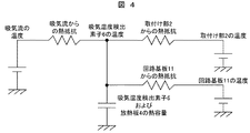
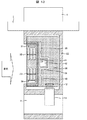
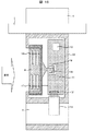
まず、本発明の第1の実施例である吸気温度センサ9を図1から図5により説明する。なお、図1は第1の実施例の吸気温度センサ9を吸気管3に実装した状態を示した実装図、図2は図1におけるA−A′の断面図、図3は第1の実施例の吸気温度センサ9の斜視図、図4は第1の実施例の熱等価回路、図5は吸気温度検出素子6の誤差特性である。
First, an intake
本発明による第1の実施例の吸気温度センサ9は図1に示すように吸気管3に設けられた開口部に挿入する形で実装され、吸気温度センサ9は取付け部2により吸気管3に固定される。また、吸気温度センサ9からの電気的接続はコネクタ部1を介して行われる。また、吸気温度センサ9には副通路8が設けられ、副通路8の内部には流量検出素子13が配置され、吸気管3を流れる流量を測定できるようにしている。また、放熱板4は吸気温度センサ9の筐体から外部に露出するように固定され、放熱板4が吸気管内の吸気流に直接曝されるように配置している。吸気温度検出素子6は、副通路8の外部かつ、回路基板11に対して吸気流れの上流側に配置されており、放熱板4に熱伝導性の高い接着剤などで機械的に固定され、放熱板4と熱的に結合する。また、吸気温度検出素子6はリード5,7を介して吸気温度センサ9の筐体22内部へ電気的に接続される。また、筐体22内部には回路基板11を配置し、回路基板11には吸気温度検出素子6および流量検出素子13の出力信号を処理するための集積回路10を配置した。なお、流量検出素子13は金線12により回路基板11に接続される。
The intake
吸気温度検出素子6はサーミスタ,白金抵抗体,熱電対,温度係数の大きい抵抗などで構成可能である。特に、吸気温度検出素子6に厚膜印刷抵抗を利用することで吸気温度検出素子6自体の熱容量を低減でき、応答性の向上を図ることができる。また、放熱板4は空気への放熱効果を高めるために、金属やセラミックなどの熱伝導率の高い材料で構成することがよい。こうすることで、放熱板4の温度は均等になるので有効放熱面積を大きくすることができる。なお、放熱板4の熱伝導率は少なくとも1W/m・k以上あることが望ましい。また、吸気温度センサ9の筐体22はプラスチップ,ポリブチレンテレフタレート樹脂,ポリフェニレンサルファイド樹脂などの熱伝導率の小さい材料で構成することがよい。こうすることで放熱板4と筐体22との接着部からの熱伝導を低減できる。
The intake air
本実施例では吸気温度検出素子6を放熱板4に固定し、吸気温度検出素子6と放熱板4を熱的に結合させることで、吸気流への放熱面積を増加させ、吸気流への熱抵抗を減少させることができる。
In the present embodiment, the intake air
本実施例の吸気温度センサ9の熱等価回路は図4に示すように表され、吸気流からの熱抵抗と取付け部2および回路基板11からの熱抵抗の比によって吸気温度検出素子6の温度は影響を受ける。このため、吸気流からの熱抵抗を小さくし、取付け部2および回路基板11からの熱抵抗を大きくすることで、吸気流の温度と吸気温度検出素子6の温度をより一致させることができる。吸気流からの熱抵抗は流速の2乗に反比例するので低流速では急激に熱抵抗が増加し、低流量では誤差が増加する。しかし、本実施例では放熱面積を増やすことで吸気流からの熱抵抗を減少させることが可能である。仮に、2分の1の流量まで対応できる吸気温度センサを実現する場合、流速は2分の1になるので、熱抵抗は4倍となる。これを放熱面積増加により対応するには4倍の面積が少なくとも必要である。
The heat equivalent circuit of the intake
図5に放熱板4の有無による吸気温度検出素子6の誤差を示す。図5からも明らかなように空気流量が小さくなり低流量領域になると誤差が増加するが、放熱板4を設けることにより検出誤差を低減できる。
FIG. 5 shows an error of the intake air
また、吸気流からの熱抵抗は吸気温度検出素子6自体の熱容量と共に熱時定数を生じさせる。この熱時定数は吸気温度の検出に時間遅れを生じさせる。なお、低流量域ではこの熱時定数は数十秒にもなり、この吸気温度センサを自動車エンジンの制御に使用する場合には制御性の悪化をもたらす。しかし、本実施例によれば吸気流への熱抵抗を低減できるので熱時定数を小さくでき、吸気温度センサの高速化を達成できる。
Further, the thermal resistance from the intake air flow causes a thermal time constant together with the heat capacity of the intake air
また、放熱板4に吸気温度検出素子6を固定することで吸気温度検出素子6の機械的保護を実現した。この結果、吸気温度センサ9を落下させても直接吸気温度検出素子6に機械的衝撃が加わることを防げる。また、吸気温度センサ9の筐体に凹部を設け、この凹部に放熱板4を配置することで放熱板4の機械的保護を実現した。この結果、吸気温度センサ9を落下させても放熱板4に機械的衝撃が加わることを防げる。
Further, the intake air
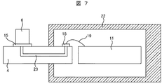
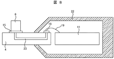
次に、本発明の第2の実施例である吸気温度センサを図6から図9により説明する。なお、図6は第2の実施例の吸気温度センサの図1におけるA−A′の断面、図7は図6におけるB−B′の断面、図8,図9は第2の実施例の変形例の図6におけるB−B′の断面である。
Next, an intake air temperature sensor according to a second embodiment of the present invention will be described with reference to FIGS. 6 is a cross section taken along the line AA 'in FIG. 1 of the intake air temperature sensor of the second embodiment, FIG. 7 is a cross section taken along the line BB' in FIG. 6, and FIGS. It is a cross section of BB 'in
第2の実施例の吸気温度センサは第1の実施例の吸気温度センサと基本的に同じ構造であるが、以下の改良を加えた。なお、先に説明した実施例と構造を同じくする部分は符号を同じとし、その説明を省略する。 The intake air temperature sensor of the second embodiment has basically the same structure as the intake air temperature sensor of the first embodiment, but the following improvements are added. Note that parts having the same structure as those of the above-described embodiment are denoted by the same reference numerals, and description thereof is omitted.
本実施例では、放熱板4にセラミック基板を用い、スリット14,17を設け、チップ型の吸気温度検出素子6を用い、半田パッド15,16を用いて吸気温度検出素子6を半田で固定した。スリット14は吸気温度検出素子6に対して取付け部2側に設けられており、放熱板4の吸気流れの垂直方向の辺に沿ってスリット14が開口されている。一方、スリット17は吸気温度検出素子6に対して副通路8側に設けられており、放熱板4の吸気流れの垂直方向の辺に沿ってスリット17が開口されている。また、スリット14,17は吸気流れに沿うように複数本のスリットが並列に配置されている。半田パッド15は図7に示す様に内層配線パターン23を介して、吸気温度センサ9の筐体22の内部の半田パッド18まで接続され、金線19を介して回路基板11へ電気的に接続される。同様に半田パッド16も内層配線パターンを介して、筐体22の内部の半田パッド21まで接続され、金線20を介して回路基板11へ電気的に接続される。
In this embodiment, a ceramic substrate is used for the heat radiating plate 4, slits 14 and 17 are provided, a chip-type intake air
本実施例では、吸気温度検出素子6を熱伝導率の高い半田を用いて放熱板4へ固定できるので、吸気温度検出素子6と放熱板4との熱結合を良好にできる。また、内層配線パターン23を用いて筐体22の内部に配線を通すことが可能になるので第1の実施例のようにリード5,7を用いるよりもより筐体内部の機密性を向上させることができる。また、スリット14,17を設け空気の通り道を設けることができるので放熱板4の表面積を増加させるとともに空気流に乱れを生じさせ放熱抵抗の低減を図れ、更に、筐体22との接触部からの熱伝導を低減することが可能である。なお、吸気温度検出素子6に本実施例ではチップ型の部品を使用したが厚膜抵抗を印刷により製作することも可能である。
In the present embodiment, since the intake air
また、図8に示す変形例のように筐体22に斜め部を設けることで吸気流がスムーズに流れるようにすることで吸気流の流速の低下を抑え、このことにより吸気流への熱抵抗の低減を達成できる。
Further, as in the modification shown in FIG. 8, by providing the
また、図9に示す変形例のように筐体22に斜め部を設けることで吸気流がスリット14,17を流れるようにすることで、吸気の流れに大きな乱れを生じさせ、吸気流への熱抵抗の低減を図ることも可能である。
Further, as shown in the modified example shown in FIG. 9, by providing the
次に、本発明の第3の実施例である吸気温度センサを図10により説明する。なお、図10は第3の実施例の吸気温度センサの図1におけるA−A′の断面である。 Next, an intake air temperature sensor according to a third embodiment of the present invention will be described with reference to FIG. FIG. 10 is a cross-sectional view taken along the line AA ′ in FIG. 1 of the intake air temperature sensor of the third embodiment.
第3の実施例の吸気温度センサは第2の実施例の吸気温度センサと基本的に同じ構造であるが、以下の改良を加えた。なお、先に説明した実施例と構造を同じくする部分は符号を同じとし、その説明を省略する。 The intake air temperature sensor of the third embodiment has basically the same structure as the intake air temperature sensor of the second embodiment, but the following improvements are added. Note that parts having the same structure as those of the above-described embodiment are denoted by the same reference numerals, and description thereof is omitted.
本実施例では、吸気温度検出素子26を吸気温度センサ9の筐体22内部に配置し、パッド24,28を用いて吸気温度検出素子26を半田で固定し、パッド24,28、金線25,27を介して回路基板11へ電気的に接続した。
In this embodiment, the intake air
本実施例では吸気温度検出素子26を筐体22の内部に配置できるので吸気温度検出素子26の保護が非常に容易になる。吸気温度センサ9は吸気管の内部に配置されるので雨の混入,ガソリン蒸気,バックファイアなどに曝されるので表面保護は非常に重要でガラス・コーティングなどが必要であったが、本実施例によれば、吸気温度検出素子26を筐体22の内部に配置できるのでガラス・コーティングなどを不要にできる。
In the present embodiment, since the intake air
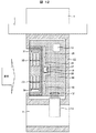
次に、本発明の第4の実施例である吸気温度センサを図11により説明する。なお、図11は第4の実施例の吸気温度センサの図1におけるA−A′の断面である。 Next, an intake air temperature sensor according to a fourth embodiment of the present invention will be described with reference to FIG. FIG. 11 is a cross-sectional view taken along the line AA ′ in FIG. 1 of the intake air temperature sensor of the fourth embodiment.
第4の実施例の吸気温度センサは第2の実施例の吸気温度センサと基本的に同じ構造であるが、以下の改良を加えた。なお、先に説明した実施例と構造を同じくする部分は符号を同じとし、その説明を省略する。 The intake air temperature sensor of the fourth embodiment has basically the same structure as the intake air temperature sensor of the second embodiment, but the following improvements are added. Note that parts having the same structure as those of the above-described embodiment are denoted by the same reference numerals, and description thereof is omitted.
本実施例では、放熱板4と回路基板11とを同一部材で構成した基板30を配置した。放熱板4には高い熱伝導率、回路基板11には配線パターンが必要であるが、これを実現する部材としてセラミック基板,メタルベース基板などを採用した。こうすることで吸気温度検出素子6から集積回路10への配線を金線を使用せずに基板30の配線パターンのみで接続可能となり、結線の信頼性向上と工数の低減による低コスト化を達成できる。また、集積回路10の自己発熱が吸気温度検出素子6へ影響しないようにスリット29を設け、集積回路10からの発熱が吸気温度検出素子6へ伝わることを防いだ。なお、本実施例の様に放熱板4と回路基板11とを同一部材で構成する場合、基板30は長方形の方が望ましい。このことから筐体22に凹部を設け、ここに放熱板4を設ける構成は以下の利点がある。第1は基板30を長方形にできる。第2は凹形状になることで吸気の導入排出がスムーズに流れる。
In this embodiment, the
次に、本発明の第5の実施例である吸気温度センサを図12により説明する。なお、図12は第5の実施例の吸気温度センサの図1におけるA−A′の断面である。 Next, an intake air temperature sensor according to a fifth embodiment of the present invention will be described with reference to FIG. FIG. 12 is a cross-sectional view taken along line AA ′ in FIG. 1 of the intake air temperature sensor of the fifth embodiment.
第5の実施例の吸気温度センサは第4の実施例の吸気温度センサと基本的に同じ構造であるが、以下の改良を加えた。なお、先に説明した実施例と構造を同じくする部分は符号を同じとし、その説明を省略する。 The intake air temperature sensor of the fifth embodiment has basically the same structure as the intake air temperature sensor of the fourth embodiment, but the following improvements are added. Note that parts having the same structure as those of the above-described embodiment are denoted by the same reference numerals, and description thereof is omitted.
本実施例では吸気温度検出素子38を筐体22の内部へ配置することで第2の実施例と同様の効果を得ることができる。また、集積回路10の自己発熱が吸気温度検出素子38へ影響しないようにスリット35,36,40を設け、集積回路10からの発熱が吸気温度検出素子38へ伝わることを防いだ。特にスリット36は吸気温度検出素子38の周囲を囲むように設けている。また、スリット35,36,40の間に隙間を作ることで配線パターンが通る領域を確保した。また、スリット31をスリット32よりも取付け部2側に吸気流れに沿って開口させ、スリット34をスリット33よりも副通路8側に吸気流れに沿って開口させることで、配置して筐体22との固定部からの熱の流入を防いだ。なお、スリット32,33により吸気流への放熱抵抗の低減を図っている。吸気温度検出素子38は半田パッド37,39より半田により固定した。
In this embodiment, the same effect as that of the second embodiment can be obtained by disposing the intake air
次に、本発明の第6の実施例である吸気温度センサを図13により説明する。なお、図13は第6の実施例の吸気温度センサの図1におけるA−A′の断面である。 Next, an intake air temperature sensor according to a sixth embodiment of the present invention will be described with reference to FIG. FIG. 13 is a cross-sectional view taken along the line AA ′ in FIG. 1 of the intake air temperature sensor of the sixth embodiment.
第6の実施例の吸気温度センサは第5の実施例の吸気温度センサと基本的に同じ構造であるが、以下の改良を加えた。なお、先に説明した実施例と構造を同じくする部分は符号を同じとし、その説明を省略する。 The intake air temperature sensor of the sixth embodiment has basically the same structure as the intake air temperature sensor of the fifth embodiment, but the following improvements are added. Note that parts having the same structure as those of the above-described embodiment are denoted by the same reference numerals, and description thereof is omitted.
本実施例では吸気温度検出素子38の変わりに温度センサ41を持つ集積回路42を配置して、温度センサ41により吸気温度を検出した。本実施例を実現するためには自己発熱を小さく抑えた集積回路42が必要であるが、本実施例に拠れば吸気温度検出素子38を無くすことができ、部品点数の低減による低コスト化が可能である。
In this embodiment, an
次に、本発明の第7の実施例である吸気温度センサを図14により説明する。なお、図14は第7の実施例の吸気温度センサの図1におけるA−A′の断面である。 Next, an intake air temperature sensor according to a seventh embodiment of the present invention will be described with reference to FIG. FIG. 14 is a cross-sectional view taken along the line AA ′ in FIG. 1 of the intake air temperature sensor of the seventh embodiment.
第7の実施例の吸気温度センサは第2の実施例の吸気温度センサと基本的に同じ構造であるが、以下の改良を加えた。なお、先に説明した実施例と構造を同じくする部分は符号を同じとし、その説明を省略する。 The intake air temperature sensor of the seventh embodiment has basically the same structure as the intake air temperature sensor of the second embodiment, but has the following improvements. Note that parts having the same structure as those of the above-described embodiment are denoted by the same reference numerals, and description thereof is omitted.
本実施例では放熱板4を金属プレート43,45に変更し、吸気温度検出素子6をリード型のサーミスタ44に変更して、サーミスタ44のリードを金属プレート43,45に接続し、金線46,47を介して回路基板11へ電気的に接続した。
In this embodiment, the heat radiating plate 4 is changed to the
これにより、本実施例では金属プレート43,45とサーミスタ44のリードを機械的,電気的、且つ、熱的にも結合することで、金属プレート43,45により吸気流への熱抵抗を低減し、金属プレート43,45に熱的に結合されるサーミスタ44の吸気流への熱抵抗を低減させた。本実施例においてもサーミスタ44から吸気流への熱抵抗を低減できるので低流量での吸気温度の検出と高速化を実現できる。なお、金属プレート43,45の放熱面積は少なくともサーミス44の表面積の4倍以上は必要である。
Thus, in this embodiment, the
次に、本発明の第8の実施例である吸気温度センサを図15により説明する。なお、図15は第8の実施例の吸気温度センサの図1におけるA−A′の断面である。 Next, an intake air temperature sensor according to an eighth embodiment of the present invention will be described with reference to FIG. FIG. 15 is a cross-sectional view taken along the line AA ′ in FIG. 1 of the intake air temperature sensor of the eighth embodiment.
第8の実施例の吸気温度センサは第2の実施例の吸気温度センサと基本的に同じ構造であるが、以下の改良を加えた。なお、先に説明した実施例と構造を同じくする部分は符号を同じとし、その説明を省略する。 The intake air temperature sensor of the eighth embodiment has basically the same structure as the intake air temperature sensor of the second embodiment, but the following improvements have been added. Note that parts having the same structure as those of the above-described embodiment are denoted by the same reference numerals, and description thereof is omitted.
本実施例では放熱板4を金属に変更し、スリット14,17を設けた。スリット14は取付け部2側に設けられており、放熱板4の吸気流れの垂直方向の辺に沿ってスリット14が開口されている。一方、スリット17は副通路8側に設けられており、放熱板4の吸気流れの垂直方向の辺に沿ってスリット17が開口されている。また、スリット14,17は吸気流れに沿うように複数本のスリットが並列に配置されている。
In this embodiment, the heat radiating plate 4 is changed to metal, and slits 14 and 17 are provided. The
また、吸気温度検出素子をリード型のサーミスタ48に変更して、サーミスタ48を筐体22の内部に配置すると共に放熱板4に機械的に固定して熱的に結合した。またサーミスタ48のリードは直接回路基板11へ接続した。
Further, the intake air temperature detecting element is changed to a
本実施例では放熱板4を吸気に曝すことで低流量でも吸気への熱抵抗を小さくすることができる。また、サーミスタ48は放熱板4と熱的に結合しているので放熱板4と同じ温度になる。本実施例では大きな放熱板4を設けることができるので低流量まで吸気流への熱抵抗を小さくすることができる。また、サーミスタ48を筐体22の内部に配置することができるのでサーミスタ48の保護を容易にできる。また、放熱板4を金属で構成できるので放熱板4の熱伝導率をセラミックなどと比べより小さくできる。
In this embodiment, by exposing the heat sink 4 to the intake air, the thermal resistance to the intake air can be reduced even at a low flow rate. Further, since the
次に、本発明の第9の実施例である吸気温度センサを図16により説明する。なお、図16は第9の実施例の吸気温度センサの図1におけるA−A′の断面である。 Next, an intake air temperature sensor according to a ninth embodiment of the present invention will be described with reference to FIG. FIG. 16 is a cross-sectional view taken along the line AA ′ in FIG. 1 of the intake air temperature sensor of the ninth embodiment.
第9の実施例の吸気温度センサ9は第8の実施例の吸気温度センサと基本的に同じ構造であるが、以下の改良を加えた。なお、先に説明した実施例と構造を同じくする部分は符号を同じとし、その説明を省略する。
The intake
本実施例では吸気温度検出素子50を回路基板11へ配置し、放熱板4の一部を伸長して吸気温度検出素子50と固定することで熱的に結合させた。また、回路からの熱影響を低減するためスリット49を設けた。スリット49は吸気温度検出素子50を取り囲むように配置され、略コの字状をしている。ただし、回路からの熱影響を低減できる形状であれば、スリット49の形状は略コの字状に限るものではなく、例えば第5の実施例で説明したようなスリット形状であってもよい。
In this embodiment, the intake air
本実施例では放熱板4を吸気に曝すことで低流量でも吸気への熱抵抗を小さくすることができる。また、吸気温度検出素子50は放熱板4と熱的に結合しているので放熱板4と同じ温度になる。本実施例では大きな放熱板4を設けることができるので低流量まで吸気流への熱抵抗を小さくすることができる。また、吸気温度検出素子50を筐体22の内部に配置することができるので吸気温度検出素子50の保護を容易にできる。また、放熱板4を金属で構成できるので放熱板4の熱伝導率をセラミックなどと比べより小さくできる。また、吸気温度検出素子50を回路基板11へ配置できるので吸気温度検出素子50の配線を容易にできる。
In this embodiment, by exposing the heat sink 4 to the intake air, the thermal resistance to the intake air can be reduced even at a low flow rate. Further, since the intake air
次に、本発明の第10の実施例である吸気温度センサを図17により説明する。なお、図17は第10の実施例の吸気温度センサの図1におけるA−A′の断面である。 Next, an intake air temperature sensor according to a tenth embodiment of the present invention will be described with reference to FIG. FIG. 17 is a cross-sectional view taken along the line AA ′ in FIG. 1 of the intake air temperature sensor of the tenth embodiment.
第10の実施例の吸気温度センサは第9の実施例の吸気温度センサと基本的に同じ構造であるが、以下の改良を加えた。なお、先に説明した実施例と構造を同じくする部分は符号を同じとし、その説明を省略する。 The intake air temperature sensor of the tenth embodiment has basically the same structure as the intake air temperature sensor of the ninth embodiment, but the following improvements have been added. Note that parts having the same structure as those of the above-described embodiment are denoted by the same reference numerals, and description thereof is omitted.
本実施例では回路基板11を無くし放熱板4の伸長部に温度センサ51を内蔵した集積回路52を配置した。また、流量検出素子13との接続はリードフレーム53,金線54を介して行った。本実施例では放熱板4を吸気に曝すことで低流量でも吸気への熱抵抗を小さくすることができる。また、集積回路52は放熱板4と熱的に結合しているので集積回路52の自己発熱を小さくすれば、放熱板4と同じ温度になる。本実施例では大きな放熱板4を設けることができるので低流量まで吸気流への熱抵抗を小さくすることができる。また、放熱板4を金属で構成できるので放熱板4の熱伝導率をセラミックと比べより小さくできる。また、温度センサ51を内蔵した集積回路52を用いることで回路基板自体を無くすことができ低コスト化が可能である。
In this embodiment, the
1 コネクタ部
2 取付け部
3 吸気管
4 放熱板
5,7 リード
6,26,38,50 吸気温度検出素子
8 副通路
9 吸気温度センサ
10,42,52 集積回路
11 回路基板
12,19,20,25,27,46,47,54 金線
13 流量検出素子
14,17,29,31,32,33,34,35,36,40,49 スリット
15,16,18,21,37,39 半田パッド
22,55 筐体
23 内層配線パターン
24,28 パッド
30 基板
41,51 温度センサ
43,45 金属プレート
44,48 サーミスタ
53 リードフレーム
DESCRIPTION OF SYMBOLS 1
Claims (12)
前記温度検出素子は、吸気管を流れる吸気流に直接曝される放熱板に機械的に接合されており、前記温度検出素子から得られる出力に基づいて吸気温度を出力することを特徴とする吸気温度センサ。 In the intake air temperature sensor in which the temperature detection element is arranged in the intake pipe by being inserted into the opening provided in the intake pipe,
The temperature detection element is mechanically joined to a heat radiating plate that is directly exposed to an intake air flow flowing through an intake pipe, and outputs an intake air temperature based on an output obtained from the temperature detection element. Temperature sensor.
前記放熱板に配線パターンを配置し、
前記配線パターンに前記温度検出素子を電気的に接続したことを特徴とする吸気温度センサ。 The intake air temperature sensor according to claim 1,
Arranging the wiring pattern on the heat sink,
An intake air temperature sensor, wherein the temperature detection element is electrically connected to the wiring pattern.
前記温度検出素子に電気的に接続される電子回路と、
前記電子回路を実装する回路基板と、
前記電子回路を収納する筐体と、を有し、
前記放熱板の一部を前記筐体内部に配置し、
前記筐体内部に配置された前記放熱板の一部に前記温度検出素子を固定したことを特徴とする吸気温度センサ。 The intake air temperature sensor according to claim 1,
An electronic circuit electrically connected to the temperature sensing element;
A circuit board on which the electronic circuit is mounted;
A housing for housing the electronic circuit,
Arranging a part of the heat sink inside the housing,
An intake air temperature sensor, wherein the temperature detection element is fixed to a part of the heat radiating plate disposed inside the housing.
前記温度検出素子に電気的に接続される電子回路と、
前記電子回路を実装する回路基板と、
前記電子回路を収納する筐体と、を有し、
前記放熱板と前記回路基板とを同一部材で構成したことを特徴とする吸気温度センサ。 The intake air temperature sensor according to claim 1,
An electronic circuit electrically connected to the temperature sensing element;
A circuit board on which the electronic circuit is mounted;
A housing for housing the electronic circuit,
An intake air temperature sensor, wherein the heat radiating plate and the circuit board are made of the same member.
前記放熱板の表面積が少なくとも前記温度検出素子の表面積の4倍以上あることを特徴とする吸気温度センサ。 The intake air temperature sensor according to claim 1,
An intake air temperature sensor characterized in that the surface area of the heat radiating plate is at least four times the surface area of the temperature detecting element.
前記放熱板が金属あるいはセラミックなどの熱伝導率の高い材料で構成したことを特徴とする吸気温度センサ。 The intake air temperature sensor according to claim 1,
An intake air temperature sensor, wherein the heat radiating plate is made of a material having high thermal conductivity such as metal or ceramic.
前記放熱板の熱伝導率が少なくとも1W/m・k以上の材料であることを特徴とする吸気温度センサ。 The intake air temperature sensor according to claim 6,
An intake air temperature sensor, wherein the heat dissipation plate is made of a material having a thermal conductivity of at least 1 W / m · k.
前記筐体がプラスチップ,ポリブチレンテレフタレート樹脂,ポリフェニレンサルファイド樹脂などの熱伝導率の小さい材料であることを特徴とする吸気温度センサ。 The intake air temperature sensor according to claim 3 or 4 ,
An intake air temperature sensor characterized in that the casing is made of a material having a low thermal conductivity such as a plus chip, polybutylene terephthalate resin, polyphenylene sulfide resin or the like.
前記吸気温度センサの筐体の一部に凹部を設け、この凹部に放熱板を配置したことを特徴とする吸気温度センサ。 The intake air temperature sensor according to claim 3 or 4 ,
An intake air temperature sensor characterized in that a recess is provided in a part of a casing of the intake air temperature sensor, and a heat radiating plate is disposed in the recess.
前記放熱板にスリット部を設けたことを特徴とする吸気温度センサ。 The intake air temperature sensor according to claim 1,
An intake air temperature sensor, wherein a slit portion is provided in the heat radiating plate.
前記スリット部は前記温度検出素子の周囲を囲むように設けられていることを特徴とする吸気温度センサ。 The intake air temperature sensor according to claim 10,
The intake air temperature sensor, wherein the slit portion is provided so as to surround the temperature detection element.
吸気管に固定する取付け部と、外部との電気的接続をするコネクタ部と、吸気流の一部を取り込む副通路と、前記副通路の内部に配置される流量検出素子と、前記温度検出素子および前記流量検出素子と電気的に接続される回路基板を収納する筐体と、を有し、
前記温度検出素子及び前記放熱板は前記副通路の外部に設けられ、
前記温度検出素子及び前記流量検出素子の出力信号を処理するための集積回路を前記回路基板に設け、
前記流量検出素子の出力信号に基づき吸気流量を検出することを特徴とする熱式流量計。 A thermal flow meter having the intake air temperature sensor according to claim 1,
An attachment portion fixed to the intake pipe, a connector portion that is electrically connected to the outside, a sub-passage that takes in a part of the intake flow, a flow rate detection element disposed in the sub-passage, and the temperature detection element And a housing for storing a circuit board electrically connected to the flow rate detection element,
The temperature detecting element and the heat radiating plate are provided outside the auxiliary passage,
An integrated circuit for processing output signals of the temperature detection element and the flow rate detection element is provided on the circuit board,
A thermal flow meter for detecting an intake flow rate based on an output signal of the flow rate detecting element.
Priority Applications (4)
| Application Number | Priority Date | Filing Date | Title |
|---|---|---|---|
| JP2010291534A JP5271997B2 (en) | 2010-12-28 | 2010-12-28 | Intake air temperature sensor |
| US13/337,398 US8813556B2 (en) | 2010-12-28 | 2011-12-27 | Intake temperature sensor |
| CN201110442664.XA CN102607738B (en) | 2010-12-28 | 2011-12-27 | Intake temperature sensor |
| EP11195862.5A EP2472236B1 (en) | 2010-12-28 | 2011-12-28 | Intake temperature sensor |
Applications Claiming Priority (1)
| Application Number | Priority Date | Filing Date | Title |
|---|---|---|---|
| JP2010291534A JP5271997B2 (en) | 2010-12-28 | 2010-12-28 | Intake air temperature sensor |
Publications (3)
| Publication Number | Publication Date |
|---|---|
| JP2012137456A JP2012137456A (en) | 2012-07-19 |
| JP2012137456A5 JP2012137456A5 (en) | 2013-02-21 |
| JP5271997B2 true JP5271997B2 (en) | 2013-08-21 |
Family
ID=45470371
Family Applications (1)
| Application Number | Title | Priority Date | Filing Date |
|---|---|---|---|
| JP2010291534A Active JP5271997B2 (en) | 2010-12-28 | 2010-12-28 | Intake air temperature sensor |
Country Status (4)
| Country | Link |
|---|---|
| US (1) | US8813556B2 (en) |
| EP (1) | EP2472236B1 (en) |
| JP (1) | JP5271997B2 (en) |
| CN (1) | CN102607738B (en) |
Families Citing this family (18)
| Publication number | Priority date | Publication date | Assignee | Title |
|---|---|---|---|---|
| DE102011005768A1 (en) * | 2011-03-18 | 2012-09-20 | Robert Bosch Gmbh | Device for detecting at least one property of a fluid medium |
| JP5629657B2 (en) * | 2011-08-03 | 2014-11-26 | トヨタ自動車株式会社 | Hybrid vehicle and control method of hybrid vehicle |
| JP5675708B2 (en) * | 2012-06-15 | 2015-02-25 | 日立オートモティブシステムズ株式会社 | Thermal flow meter |
| CA2896601C (en) * | 2012-12-04 | 2021-08-31 | Fisher & Paykel Healthcare Limited | Medical tubes and methods of manufacture |
| JP5884769B2 (en) | 2013-05-09 | 2016-03-15 | 株式会社デンソー | Air flow measurement device |
| JP6013983B2 (en) * | 2013-06-20 | 2016-10-25 | 日立オートモティブシステムズ株式会社 | Physical quantity measuring device |
| JP6142840B2 (en) * | 2014-04-28 | 2017-06-07 | 株式会社デンソー | Air flow measurement device |
| WO2016017300A1 (en) * | 2014-07-30 | 2016-02-04 | 日立オートモティブシステムズ株式会社 | Physical-quantity detection device |
| JP5826355B1 (en) * | 2014-10-03 | 2015-12-02 | 三菱電機株式会社 | Flow measuring device |
| JP6358154B2 (en) * | 2015-04-08 | 2018-07-18 | 株式会社デンソー | Temperature sensor and its mounting structure |
| CN104864945A (en) * | 2015-06-12 | 2015-08-26 | 武汉飞恩微电子有限公司 | Flow sensor batch test pipeline system based on sampling flow passages |
| US10591332B2 (en) * | 2015-08-31 | 2020-03-17 | Hitachi Automotive Systems, Ltd. | Airflow meter |
| US10584987B2 (en) | 2015-09-30 | 2020-03-10 | Hitachi Automotive Systems, Ltd. | Physical quantity detection device |
| CN108027265B (en) * | 2015-09-30 | 2020-01-14 | 日立汽车系统株式会社 | Physical quantity detecting device |
| JP6855590B2 (en) * | 2017-09-29 | 2021-04-07 | 日立Astemo株式会社 | Physical quantity detector |
| CN108508152A (en) * | 2018-03-30 | 2018-09-07 | 风纹物联(深圳)技术有限公司 | Air quality detector |
| CN112136024B (en) * | 2018-05-17 | 2023-08-18 | 日立安斯泰莫株式会社 | Physical quantity detecting device |
| DE102019134440A1 (en) * | 2019-12-16 | 2021-06-17 | Endress + Hauser Wetzer Gmbh + Co. Kg | Measuring device |
Family Cites Families (16)
| Publication number | Priority date | Publication date | Assignee | Title |
|---|---|---|---|---|
| US4911008A (en) * | 1988-10-03 | 1990-03-27 | Allied-Signal Inc. | Hot film anemometer |
| JPH05231899A (en) * | 1992-02-25 | 1993-09-07 | Aisan Ind Co Ltd | Intake air amount detector |
| DE19504572C2 (en) | 1995-02-11 | 1999-02-04 | Hella Kg Hueck & Co | Temperature sensor arrangement |
| JP3475579B2 (en) * | 1995-06-20 | 2003-12-08 | 株式会社デンソー | Mounting structure of intake air temperature sensor and thermal flow meter using it |
| DE19802045A1 (en) | 1998-01-21 | 1999-07-22 | Behr Gmbh & Co | Temperature detector for passing medium in heating or air conditioning system in motor vehicle |
| DE19823685C2 (en) | 1998-05-27 | 2000-12-07 | Siemens Ag | Electronic control device for a motor vehicle |
| DE19905384A1 (en) | 1999-02-10 | 2000-08-17 | Holzschuh Gmbh & Co Kg | Sensor and method for its production |
| JP3557379B2 (en) * | 2000-01-24 | 2004-08-25 | 株式会社日立製作所 | Air flow measurement device |
| WO2002010694A1 (en) | 2000-07-27 | 2002-02-07 | Hitachi, Ltd. | Thermal type air flowmeter |
| JP2003139593A (en) * | 2001-11-07 | 2003-05-14 | Hitachi Ltd | On-vehicle electronic apparatus and thermal flowmeter |
| US6845661B2 (en) * | 2002-10-11 | 2005-01-25 | Visteon Global Technologies, Inc. | Lead frame for automotive electronics |
| JP2006058078A (en) * | 2004-08-18 | 2006-03-02 | Hitachi Ltd | Thermal air flowmeter |
| JP4020208B2 (en) * | 2004-11-30 | 2007-12-12 | 三菱電機株式会社 | Flow measuring device |
| WO2007091686A1 (en) | 2006-02-09 | 2007-08-16 | Mitsui Mining & Smelting Co., Ltd. | Laminate, thin film sensor, thin film sensor module, and method for manufacturing the thin film sensor |
| DE102007024865A1 (en) * | 2007-05-29 | 2008-12-04 | Robert Bosch Gmbh | Device for determining at least one parameter of a fluid medium |
| JP4426606B2 (en) | 2007-06-29 | 2010-03-03 | 三菱電機株式会社 | Flow measuring device |
-
2010
- 2010-12-28 JP JP2010291534A patent/JP5271997B2/en active Active
-
2011
- 2011-12-27 CN CN201110442664.XA patent/CN102607738B/en active Active
- 2011-12-27 US US13/337,398 patent/US8813556B2/en active Active
- 2011-12-28 EP EP11195862.5A patent/EP2472236B1/en active Active
Also Published As
| Publication number | Publication date |
|---|---|
| EP2472236A1 (en) | 2012-07-04 |
| US8813556B2 (en) | 2014-08-26 |
| CN102607738B (en) | 2014-11-05 |
| US20120160024A1 (en) | 2012-06-28 |
| EP2472236B1 (en) | 2020-02-12 |
| JP2012137456A (en) | 2012-07-19 |
| CN102607738A (en) | 2012-07-25 |
Similar Documents
| Publication | Publication Date | Title |
|---|---|---|
| JP5271997B2 (en) | Intake air temperature sensor | |
| JP5279667B2 (en) | Thermal air flow sensor | |
| EP2482050B1 (en) | Intake air temperature sensor and thermal airflow meter including the same | |
| EP3217153B1 (en) | Thermal air flow meter | |
| US20030019289A1 (en) | Air flow meter | |
| JP4707412B2 (en) | Gas flow measuring device | |
| CN107949783B (en) | Gas sensor device | |
| JP5093052B2 (en) | Thermal flow sensor | |
| JP4166705B2 (en) | Air flow measurement device | |
| JP5814192B2 (en) | Flow measuring device | |
| JP6851466B2 (en) | Humidity measuring device | |
| JP6945376B2 (en) | Sensor device | |
| CN110741232A (en) | Sensor for sensing at least characteristics of a fluid medium | |
| JP6200962B2 (en) | Air flow measurement device | |
| JP6507804B2 (en) | Air flow measuring device | |
| JP5609841B2 (en) | Flow sensor | |
| JP2020079808A (en) | Thermal air flowmeter | |
| JP5092887B2 (en) | Concentration detector | |
| JP2017187512A (en) | Flow rate measurement device | |
| JP2014035200A (en) | Physical quantity sensor |
Legal Events
| Date | Code | Title | Description |
|---|---|---|---|
| RD04 | Notification of resignation of power of attorney |
Free format text: JAPANESE INTERMEDIATE CODE: A7424 Effective date: 20120521 |
|
| A521 | Request for written amendment filed |
Free format text: JAPANESE INTERMEDIATE CODE: A523 Effective date: 20121130 |
|
| A621 | Written request for application examination |
Free format text: JAPANESE INTERMEDIATE CODE: A621 Effective date: 20121130 |
|
| A521 | Request for written amendment filed |
Free format text: JAPANESE INTERMEDIATE CODE: A523 Effective date: 20121130 |
|
| A977 | Report on retrieval |
Free format text: JAPANESE INTERMEDIATE CODE: A971007 Effective date: 20130408 |
|
| TRDD | Decision of grant or rejection written | ||
| A01 | Written decision to grant a patent or to grant a registration (utility model) |
Free format text: JAPANESE INTERMEDIATE CODE: A01 Effective date: 20130416 |
|
| A61 | First payment of annual fees (during grant procedure) |
Free format text: JAPANESE INTERMEDIATE CODE: A61 Effective date: 20130513 |
|
| R150 | Certificate of patent or registration of utility model |
Ref document number: 5271997 Country of ref document: JP Free format text: JAPANESE INTERMEDIATE CODE: R150 Free format text: JAPANESE INTERMEDIATE CODE: R150 |
|
| S533 | Written request for registration of change of name |
Free format text: JAPANESE INTERMEDIATE CODE: R313533 |
|
| R350 | Written notification of registration of transfer |
Free format text: JAPANESE INTERMEDIATE CODE: R350 |
|
| R250 | Receipt of annual fees |
Free format text: JAPANESE INTERMEDIATE CODE: R250 |