JP5267874B2 - Signal processing apparatus and signal processing method - Google Patents
Signal processing apparatus and signal processing method Download PDFInfo
- Publication number
- JP5267874B2 JP5267874B2 JP2009173591A JP2009173591A JP5267874B2 JP 5267874 B2 JP5267874 B2 JP 5267874B2 JP 2009173591 A JP2009173591 A JP 2009173591A JP 2009173591 A JP2009173591 A JP 2009173591A JP 5267874 B2 JP5267874 B2 JP 5267874B2
- Authority
- JP
- Japan
- Prior art keywords
- frequency offset
- signal
- ofdm
- frequency
- unit
- Prior art date
- Legal status (The legal status is an assumption and is not a legal conclusion. Google has not performed a legal analysis and makes no representation as to the accuracy of the status listed.)
- Expired - Fee Related
Links
Images


Classifications
-
- H—ELECTRICITY
- H04—ELECTRIC COMMUNICATION TECHNIQUE
- H04L—TRANSMISSION OF DIGITAL INFORMATION, e.g. TELEGRAPHIC COMMUNICATION
- H04L27/00—Modulated-carrier systems
- H04L27/26—Systems using multi-frequency codes
- H04L27/2601—Multicarrier modulation systems
- H04L27/2647—Arrangements specific to the receiver only
- H04L27/2655—Synchronisation arrangements
- H04L27/2662—Symbol synchronisation
- H04L27/2665—Fine synchronisation, e.g. by positioning the FFT window
-
- H—ELECTRICITY
- H04—ELECTRIC COMMUNICATION TECHNIQUE
- H04L—TRANSMISSION OF DIGITAL INFORMATION, e.g. TELEGRAPHIC COMMUNICATION
- H04L27/00—Modulated-carrier systems
- H04L27/26—Systems using multi-frequency codes
- H04L27/2601—Multicarrier modulation systems
- H04L27/2647—Arrangements specific to the receiver only
- H04L27/2655—Synchronisation arrangements
- H04L27/2657—Carrier synchronisation
- H04L27/2659—Coarse or integer frequency offset determination and synchronisation
-
- H—ELECTRICITY
- H04—ELECTRIC COMMUNICATION TECHNIQUE
- H04L—TRANSMISSION OF DIGITAL INFORMATION, e.g. TELEGRAPHIC COMMUNICATION
- H04L27/00—Modulated-carrier systems
- H04L27/26—Systems using multi-frequency codes
- H04L27/2601—Multicarrier modulation systems
- H04L27/2647—Arrangements specific to the receiver only
- H04L27/2655—Synchronisation arrangements
- H04L27/2657—Carrier synchronisation
- H04L27/266—Fine or fractional frequency offset determination and synchronisation
-
- H—ELECTRICITY
- H04—ELECTRIC COMMUNICATION TECHNIQUE
- H04L—TRANSMISSION OF DIGITAL INFORMATION, e.g. TELEGRAPHIC COMMUNICATION
- H04L27/00—Modulated-carrier systems
- H04L27/26—Systems using multi-frequency codes
- H04L27/2601—Multicarrier modulation systems
- H04L27/2647—Arrangements specific to the receiver only
- H04L27/2655—Synchronisation arrangements
- H04L27/2668—Details of algorithms
- H04L27/2673—Details of algorithms characterised by synchronisation parameters
- H04L27/2675—Pilot or known symbols
-
- H—ELECTRICITY
- H04—ELECTRIC COMMUNICATION TECHNIQUE
- H04L—TRANSMISSION OF DIGITAL INFORMATION, e.g. TELEGRAPHIC COMMUNICATION
- H04L27/00—Modulated-carrier systems
- H04L27/26—Systems using multi-frequency codes
- H04L27/2601—Multicarrier modulation systems
- H04L27/2647—Arrangements specific to the receiver only
- H04L27/2655—Synchronisation arrangements
- H04L27/2668—Details of algorithms
- H04L27/2681—Details of algorithms characterised by constraints
- H04L27/2685—Speed of convergence
-
- H—ELECTRICITY
- H04—ELECTRIC COMMUNICATION TECHNIQUE
- H04L—TRANSMISSION OF DIGITAL INFORMATION, e.g. TELEGRAPHIC COMMUNICATION
- H04L27/00—Modulated-carrier systems
- H04L27/26—Systems using multi-frequency codes
- H04L27/2601—Multicarrier modulation systems
- H04L27/2647—Arrangements specific to the receiver only
- H04L27/2655—Synchronisation arrangements
- H04L27/2666—Acquisition of further OFDM parameters, e.g. bandwidth, subcarrier spacing, or guard interval length
Landscapes
- Engineering & Computer Science (AREA)
- Computer Networks & Wireless Communication (AREA)
- Signal Processing (AREA)
- Mobile Radio Communication Systems (AREA)
- Synchronisation In Digital Transmission Systems (AREA)
Abstract
Description
本発明は、信号処理装置、及び、信号処理方法に関し、特に、例えば、OFDM(Orthogonal Frequency Division Multiplexing)信号の復調を迅速に行うことができるようにする信号処理装置、及び、信号処理方法関する。 The present invention relates to a signal processing device and a signal processing method, and more particularly, to a signal processing device and a signal processing method that enable rapid demodulation of an OFDM (Orthogonal Frequency Division Multiplexing) signal, for example.
地上ディジタル放送等では、データ(信号)の変調方式として、OFDM(Orthogonal Frequency Division Multiplexing)(直交周波数分割多重)が採用されている。 In digital terrestrial broadcasting and the like, OFDM (Orthogonal Frequency Division Multiplexing) (orthogonal frequency division multiplexing) is employed as a data (signal) modulation method.
OFDMでは、伝送帯域内に多数の直交するサブキャリア(副搬送波)を使用し、それぞれのサブキャリアの振幅や位相にデータを割り当る、PSK(Phase Shift Keying)やQAM(Quadrature Amplitude Modulation)等のディジタル変調が行われる。 In OFDM, a large number of orthogonal subcarriers (subcarriers) are used in the transmission band, and data is allocated to the amplitude and phase of each subcarrier, such as PSK (Phase Shift Keying) and QAM (Quadrature Amplitude Modulation). Digital modulation is performed.
OFDMでは、多数のサブキャリアで伝送帯域を分割するため、1つ(1波)のサブキャリアあたりの帯域は狭くなり、変調速度は遅くなるが、トータル(サブキャリアの全体)の伝送速度は、従来の変調方式と変わらない。 In OFDM, since the transmission band is divided by a large number of subcarriers, the band per one (one wave) subcarrier is narrowed and the modulation speed is slow, but the total (subcarrier total) transmission speed is It is not different from the conventional modulation method.
上述したように、OFDMにおいては、複数のサブキャリアに対してデータの割り当てが行われることから、変調は、逆フーリエ変換を行うIFFT(Inverse Fast Fourier Transform)演算によって行うことができる。また、変調の結果得られるOFDM信号の復調は、フーリエ変換を行うFFT(Fast Frourier Transform)演算によって行うことができる。 As described above, in OFDM, data is allocated to a plurality of subcarriers, so that modulation can be performed by IFFT (Inverse Fast Fourier Transform) calculation that performs inverse Fourier transform. Further, the demodulation of the OFDM signal obtained as a result of the modulation can be performed by FFT (Fast Frourier Transform) calculation that performs Fourier transform.
したがって、OFDM信号を送信するOFDM送信装置は、IFFT演算を行う回路を用いて構成することができ、OFDM信号を受信するOFDM受信装置は、FFT演算を行う回路を用いて構成することができる。 Therefore, an OFDM transmitter that transmits an OFDM signal can be configured using a circuit that performs an IFFT operation, and an OFDM receiver that receives an OFDM signal can be configured using a circuit that performs an FFT operation.
また、OFDMでは、ガードインターバルと呼ばれる信号区間を設けることで、マルチパスに対する耐性を向上させるている。さらに、OFDMでは、既知の信号(OFDM受信装置側で分かっている信号)であるパイロット信号が、時間方向や周波数方向に離散的に挿入され、OFDM受信装置では、そのパイロット信号が、同期や、伝送路(チャネル)特性の推定等に利用される。 In OFDM, the resistance against multipath is improved by providing a signal section called a guard interval. Further, in OFDM, a pilot signal which is a known signal (a signal known on the OFDM receiver side) is discretely inserted in the time direction and the frequency direction. In the OFDM receiver, the pilot signal is synchronized, This is used for estimating transmission channel characteristics.
OFDMは、マルチパスに対する耐性が強いため、マルチパス妨害の影響を強く受ける地上ディジタル放送等で採用されている。OFDMを採用した地上ディジタル放送の規格としては、例えば、DVB-T(Digital Video Broadcasting-Terrestrial)や、ISDB-T(Integrated Services Digital Broadcasting-Terrestrial)等がある。 Since OFDM is highly resistant to multipath, it is used in terrestrial digital broadcasting that is strongly affected by multipath interference. Examples of terrestrial digital broadcasting standards that employ OFDM include DVB-T (Digital Video Broadcasting-Terrestrial) and ISDB-T (Integrated Services Digital Broadcasting-Terrestrial).
OFDMでは、データは、OFDMシンボルと呼ばれる単位で送信(伝送)される。 In OFDM, data is transmitted (transmitted) in units called OFDM symbols.
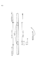
図1は、OFDMシンボルを示す図である。 FIG. 1 is a diagram illustrating OFDM symbols.
OFDMシンボルは、一般に、変調時にIFFTが行われる信号期間である有効シンボルと、その有効シンボルの後半の一部の波形が、そのまま、有効シンボルの先頭にコピーされたガードインターバルとから構成される。 The OFDM symbol generally includes an effective symbol that is a signal period during which IFFT is performed during modulation, and a guard interval in which a partial waveform of the latter half of the effective symbol is copied to the head of the effective symbol as it is.
このように、OFDMシンボルの先頭に、ガードインターバルを設けることで、マルチパスに対する耐性を向上させることができる。 Thus, by providing a guard interval at the beginning of an OFDM symbol, it is possible to improve resistance to multipath.
なお、OFDMを採用した地上ディジタル放送の規格では、複数のOFDMシンボルによって構成されるフレーム(OFDM伝送フレーム)と呼ばれる単位が定義され、データの送信は、フレーム単位で行われる。 In the terrestrial digital broadcasting standard adopting OFDM, a unit called a frame (OFDM transmission frame) composed of a plurality of OFDM symbols is defined, and data transmission is performed in frame units.
以上のような、OFDM信号を受信するOFDM受信装置では、OFDM信号のキャリアを用いて、OFDM信号のディジタル直交復調が行われる。 In the OFDM receiver that receives an OFDM signal as described above, digital orthogonal demodulation of the OFDM signal is performed using the carrier of the OFDM signal.
但し、OFDM受信装置でディジタル直交復調に用いられるOFDM信号のキャリアは、一般に、OFDM信号を送信してくるOFDM送信装置で用いられるOFDM信号のキャリアと一致しておらず、誤差を含む。すなわち、ディジタル直交復調に用いられるOFDM信号のキャリアの周波数は、OFDM受信装置で受信されたOFDM信号(のIF(Intermidiate Frequency)信号)の中心周波数からずれている。 However, an OFDM signal carrier used for digital orthogonal demodulation in an OFDM receiver generally does not coincide with an OFDM signal carrier used in an OFDM transmitter that transmits an OFDM signal, and includes an error. That is, the frequency of the carrier of the OFDM signal used for digital orthogonal demodulation is shifted from the center frequency of the OFDM signal (the IF (Intermidiate Frequency) signal) received by the OFDM receiver.
そのため、OFDM受信装置では、ディジタル直交復調に用いられるOFDM信号のキャリアの誤差である周波数オフセットを推定し、その推定値を検出する周波数オフセット検出、及び、周波数オフセットの推定値に従い、周波数オフセットをなくすように、OFDM信号(の周波数オフセット)を補正する周波数オフセット補正が行われる。 Therefore, the OFDM receiver estimates the frequency offset, which is the error of the OFDM signal carrier used for digital orthogonal demodulation, and eliminates the frequency offset according to the frequency offset detection that detects the estimated value and the estimated value of the frequency offset. As described above, frequency offset correction for correcting the OFDM signal (frequency offset thereof) is performed.
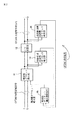
図2は、従来のOFDM受信装置の一例の構成を示すブロック図である。 FIG. 2 is a block diagram showing a configuration of an example of a conventional OFDM receiver.
周波数オフセット補正部11には、OFDM信号のディジタル直交復調後に得られるベースバンドの、時間領域のOFDM信号(OFDM時間領域信号)が供給される。
The frequency
周波数オフセット補正部11は、後述する周波数オフセット補正量推定部15から供給される周波数オフセットの補正量に従い、そこに供給されるOFDM時間領域信号(の周波数オフセット)を補正する周波数オフセット補正を行う。
The frequency
そして、周波数オフセット補正部11は、周波数オフセット補正後のOFDM時間領域信号を、FFT演算部12、及び、時間領域周波数オフセット検出部13に供給する。
Then, the frequency
FFT演算部12は、周波数オフセット補正部11からのOFDM時間領域信号を、周波数領域のOFDM信号(OFDM周波数領域信号)にフーリエ変換する変換演算としてのFFT演算を行い、その結果得られるOFDM周波数領域信号を、周波数領域周波数オフセット検出部14に供給する。
The
なお、FFT演算部12で得られるOFDM周波数領域信号は、周波数領域周波数オフセット検出部14の他、等化や、誤り訂正符号の復号等を行う図示せぬ後段のブロックにも供給される。
Note that the OFDM frequency domain signal obtained by the
時間領域周波数オフセット検出部13は、周波数オフセット補正部11からのOFDM時間領域信号を用いて、OFDM時間領域信号の周波数オフセットを推定することにより、その推定値を検出する周波数オフセット検出を行う。そして、時間領域周波数オフセット検出部13は、周波数オフセット検出の結果得られる周波数オフセットの推定値を、周波数オフセット補正量推定部15に供給(フィードバック)する。
The time domain frequency
周波数領域周波数オフセット検出部14は、FFT演算部12からのOFDM時間領域信号を用いて、OFDM周波数領域信号の周波数オフセットを推定することにより、その推定値を検出する周波数オフセット検出を行う。そして、周波数領域周波数オフセット検出部14は、周波数オフセット検出の結果得られる周波数オフセットの推定値を、周波数オフセット補正量推定部15に供給(フィードバック)する。
The frequency domain frequency
周波数オフセット補正量推定部15は、時間領域周波数オフセット検出部13からの周波数オフセットの推定値、及び、周波数領域周波数オフセット検出部14からの周波数オフセットの推定値のうちの一方、又は、両方を用いて、OFDM時間領域信号の周波数オフセットをなくすための(OFDM時間領域信号の)補正量を推定し、その補正量を、周波数オフセット補正部11に供給する。
The frequency offset correction
上述したように、周波数オフセット補正部11は、周波数オフセット補正量推定部15からの補正量に従い、そこに供給されるOFDM時間領域信号を補正する(周波数オフセット補正を行う)。
As described above, the frequency
ところで、OFDMを採用する地上ディジタル放送の規格として、DVB-T2(第2世代欧州地上ディジタル放送規格)が策定されつつある。 By the way, DVB-T2 (2nd generation European terrestrial digital broadcasting standard) is being formulated as a terrestrial digital broadcasting standard adopting OFDM.
なお、DVB-T2については、いわゆるブルーブック(DVB BlueBook A122)に記載されている(非特許文献1)。 Note that DVB-T2 is described in the so-called Blue Book (DVB BlueBook A122) (Non-Patent Document 1).
DVB-T2(のブルーブック)では、T2フレーム(T2 frame)と呼ばれるフレームが定義され、データは、T2フレーム単位で送信される。 DVB-T2 (Blue Book) defines a frame called a T2 frame, and data is transmitted in units of T2 frames.
T2フレーム(のOFDM信号)は、P1及びP2と呼ばれる2種類のプリアンブル(Preamble)信号を含み、そのプリアンブル信号には、OFDM信号の復調等の処理に必要な情報が含まれる(シグナリング(signalling)されている)。 The T2 frame (OFDM signal) includes two types of preamble signals called P1 and P2, and the preamble signal includes information necessary for processing such as demodulation of the OFDM signal (signaling). Have been).
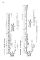
図3は、T2フレームのフォーマットを示す図である。 FIG. 3 is a diagram illustrating a format of the T2 frame.
T2フレームには、1個のOFDMシンボルのP1のシンボル、1個以上のOFDMシンボルのP2のシンボル、1個以上のOFDMシンボルのデータ(Normal)のシンボル、及び、必要なFC(Frame Closing)のOFDMシンボルが、その順で含まれる。 The T2 frame includes one OFDM symbol P1 symbol, one or more OFDM symbol P2 symbols, one or more OFDM symbol data (Normal) symbols, and necessary FC (Frame Closing) symbols. OFDM symbols are included in that order.
P1には、ビットS1及びS2等がシグナリング(Signalling)される。 Bits S1 and S2 are signaled in P1.
ビットS1及びS2は、P1以外のシンボル(P2、データ、及び、FCのシンボル)が、SISO(Single Input Single Output)、及び、MISO(Multiple Input, Single Output)のうちのいずれの方式(伝送方式)で伝送されてくるのかや、P1以外のシンボルのFFT演算を行うときのFFTサイズ(1回のFFT演算の対象とするサンプル(シンボル)(サブキャリア)の数)、カードインターバルの長さ(以下、GI長ともいう)が、2つのグループのうちのいずれのグループに属するか等を表す。 For bits S1 and S2, symbols other than P1 (P2, data, and FC symbols) are either SISO (Single Input Single Output) or MISO (Multiple Input, Single Output). ), FFT size when performing FFT operation on symbols other than P1 (number of samples (symbols) (subcarriers) subject to one FFT operation), card interval length ( (Hereinafter also referred to as GI length) represents which of the two groups belongs.
なお、DVB-T2では、GI長として、有効シンボルの長さを基準(1)とする7種類の値1/128, 1/32, 1/16, 19/256, 1/8, 19/128, 1/4が規定されている。この7種類のGI長が、2つのグループに分けられており、P1にシグナリングされているビットS1及びS2は、T2フレームのGI長が、2つのグループのうちのいずれのグループに属するかのグループ情報を含む。 In DVB-T2, as the GI length, seven values with the effective symbol length as the standard (1) are 1/128, 1/32, 1/16, 19/256, 1/8, 19/128 , 1/4 is specified. These seven types of GI lengths are divided into two groups. Bits S1 and S2 signaled to P1 are groups that indicate which of the two groups the GI length of the T2 frame belongs to. Contains information.
また、DVB-T2では、1個のOFDMシンボルを構成するシンボル(サブキャリア)の数、つまり、FFTサイズとしては、1K,2K,4K,8K,16K、及び、32Kの6種類が規定されている。 In DVB-T2, the number of symbols (subcarriers) constituting one OFDM symbol, that is, six types of FFT sizes, 1K, 2K, 4K, 8K, 16K, and 32K, are defined. Yes.
但し、P1以外のOFDMシンボルについては、上述の6種類のFFTサイズのいずれも使用可能であるが、P1のOFDMシンボルについては、上述の6種類のFFTサイズのうちの、1Kのみが使用される。 However, for the OFDM symbols other than P1, any of the six types of FFT sizes described above can be used, but for the OFDM symbol of P1, only 1K of the six types of FFT sizes described above is used. .
また、P2のFFTサイズ、及び、GI長としては、P1及びP2以外のOFDMシンボル、すなわち、データ(Normal)、及び、FCのOFDMシンボルと同一の値が採用される。 Also, as the FFT size and GI length of P2, the same values as those of OFDM symbols other than P1 and P2, that is, data (Normal) and FC OFDM symbols are employed.
ここで、P1は、P2の復調に必要な伝送方式やFFTサイズ等を含むので、P2を復調するには、P1を復調する必要がある。 Here, since P1 includes a transmission method, an FFT size, and the like necessary for demodulating P2, it is necessary to demodulate P1 in order to demodulate P2.
P2には、L1プレ(L1 PRE)、及び、L1ポスト(L1 POST)がシグナリング(signalling)される。 In P2, L1 pre (L1 PRE) and L1 post (L1 POST) are signaled.
L1プレは、T2フレームを受信するOFDM受信装置が、L1ポストの復号を行うのに必要な情報を含む。L1ポストは、OFDM受信装置が、物理レイヤ(のlayer pipes)にアクセスするのに必要な情報を含む。 The L1 pre includes information necessary for the OFDM receiver that receives the T2 frame to decode the L1 post. The L1 post contains information necessary for the OFDM receiver to access the physical layer (layer pipes).
ここで、L1プレには、GI長、どのシンボル(サブキャリア)に、既知の信号であるパイロット信号が含まれるかのパイロット信号の配置を表すパイロットパターン(PP)、OFDM信号を伝送する伝送帯域の拡張の有無(BWT_EXT)、1つのT2フレームに含まれるOFDMシンボルの数(NDSYM)等が含まれ、これらは、データ(FCを含む)のシンボルを復調するのに必要な情報となっている。 Here, the L1 pre has a GI length, a pilot pattern (PP) indicating a pilot signal arrangement indicating which symbol (subcarrier) includes a pilot signal which is a known signal, and a transmission band for transmitting an OFDM signal (BWT_EXT), the number of OFDM symbols included in one T2 frame (NDSYM), etc., are included, and these are information necessary for demodulating data (including FC) symbols. .
OFDM受信装置では、L1プレ、及び、L1ポスト(にシグナリングされている情報)を取得すると、その後、データ(及びFC)のシンボルを復調することが可能となる。 In the OFDM receiver, when the L1 pre and L1 post (information signaled in) is acquired, it is possible to demodulate data (and FC) symbols thereafter.
なお、図3では、T2フレームに、2個のOFDMシンボルのP2が配置されているが、T2フレームには、1ないし16個のOFDMシンボルのP2を配置することができる。但し、FFTサイズが16Kと32KのP2を含むT2フレームには、1個のOFDMシンボルだけのP2が配置される。 In FIG. 3, P2 of two OFDM symbols is arranged in the T2 frame, but P2 of 1 to 16 OFDM symbols can be arranged in the T2 frame. However, in a T2 frame including P2 having an FFT size of 16K and 32K, P2 having only one OFDM symbol is arranged.
図4は、P1のOFDM信号を示す図である。 FIG. 4 is a diagram illustrating an OFDM signal of P1.
P1のOFDM信号は、1K(=1024)個のシンボルを有効シンボルとして有する。 The OFDM signal of P1 has 1K (= 1024) symbols as effective symbols.
そして、P1のOFDM信号は、有効シンボルの、先頭側の一部分B1を周波数シフトした信号B1'を、有効シンボルの前側にコピーし、かつ、有効シンボルの残りの部分B2を周波数シフトした信号B2'を、有効シンボルの後ろ側にコピーした、サイクリック(cyclic)な構造になっている。 Then, the OFDM signal of P1 is a signal B2 ′ obtained by copying the signal B1 ′ obtained by frequency-shifting the first part B1 of the effective symbol to the front side of the effective symbol and frequency-shifting the remaining part B2 of the effective symbol Is a cyclic structure in which is copied to the back of the effective symbol.
P1のOFDM信号は、853本のサブキャリアを、有効なサブキャリアとして有し、DVB-T2では、その853本のサブキャリアのうちの、所定の位置の384本のサブキャリアに、情報の割り当て(location)がされている。 The OFDM signal of P1 has 853 subcarriers as effective subcarriers, and DVB-T2 allocates information to 384 subcarriers at predetermined positions among the 853 subcarriers. (location) has been done.
DVB-T2のインプリメンテーションガイドライン(Implementation Guidelines(ETSI TR 102 831 : IG))によれば、OFDM信号を送信する伝送帯域が、例えば、8MHzである場合、P1のOFDM信号の、上述の384本のサブキャリアのロケーションの相関性を利用して、最大で±500kHzの範囲の、サブキャリア間隔の単位での「粗い」周波数オフセット("coarse" carrier frequency offset)の推定が可能である。
According to the Implementation Guidelines (Emplementation Guidelines (
さらに、インプリメンテーションガイドラインによれば、図4で説明したP1のサイクリックな構造によって、±0.5×サブキャリア間隔の範囲の、サブキャリア間隔未満の単位での「細かい」周波数オフセット("fine" carrier frequency offset)の推定が可能である。 Further, according to the implementation guideline, the “fine” frequency offset (“fine”) in the range of ± 0.5 × subcarrier interval is less than the subcarrier interval due to the cyclic structure of P1 described in FIG. (carrier frequency offset) can be estimated.
ここで、DVB-T2では、P1のFFTサイズが、図4で説明した1Kサンプル(シンボル)であることが規定されている。 Here, DVB-T2 stipulates that the FFT size of P1 is the 1K sample (symbol) described with reference to FIG.
さらに、DVB-T2では、伝送帯域が、例えば、8MHzである場合には、FFTサイズが1KサンプルのP1のサンプリング周期が、7/64μ秒であることが規定されている。 Furthermore, DVB-T2 stipulates that when the transmission band is 8 MHz, for example, the sampling period of P1 with an FFT size of 1K samples is 7/64 μsec.
したがって、伝送帯域が、例えば、8MHzである場合、P1の有効シンボル長Tuは、1024×7/64μ秒である Thus, the transmission band is, for example, if it is 8 MHz, the effective symbol length T u of P1 is a 1024 × 7 / 64μ sec
一方、OFDMシンボルの有効シンボルの長さ(ガードインターバルを含まない長さである有効シンボル長)Tu[秒]と、OFDM信号のサブキャリアのサブキャリア間隔D[Hz]との間には、式D=1/Tuの関係が成り立つ。 On the other hand, between the effective symbol length of OFDM symbols (effective symbol length that does not include the guard interval) Tu [second] and the subcarrier interval D [Hz] of the subcarrier of the OFDM signal, The relationship of the formula D = 1 / T u is established.
したがって、伝送帯域が、例えば、8MHzである場合、P1のサブキャリアのサブキャリア間隔Dは、有効シンボル長Tu=1024×7/64μ秒の逆数である約8929Hzとなる。 Thus, the transmission band is, for example, if it is 8 MHz, the subcarrier spacing D of the subcarriers of P1 becomes the reciprocal of the effective symbol length T u = 1024 × 7 / 64μ sec to about 8,929 Hz.
以上のように、P1のサブキャリア間隔Dは、(約)8929Hzであるから、P1を用いて検出することができる「細かい」周波数オフセットの推定値は、±8929/2Hzの範囲の値となる。 As described above, since the subcarrier interval D of P1 is (about) 8929 Hz, the estimated value of the “fine” frequency offset that can be detected using P1 is a value in the range of ± 8929/2 Hz. .
この場合、P1によるキャプチャレンジ、すなわち、P1から得られる「細かい」周波数オフセットの推定値に従ったOFDM信号の補正によって、ディジタル直交復調に用いられるOFDM信号のキャリアを引き込むことのできる範囲(周波数オフセット補正をすることができる範囲)は、サブキャリアの本来の周波数軸上の位置(周波数)を基準とする±8929/2Hzの範囲内(-8929/2Hzないし+8929/2Hzの範囲内)となる。 In this case, the capture range by P1, that is, the range in which the carrier of the OFDM signal used for digital quadrature demodulation can be drawn by correcting the OFDM signal according to the “fine” frequency offset estimate obtained from P1 (frequency offset) The range that can be corrected) is within the range of ± 8929 / 2Hz (within the range of -8929 / 2Hz to + 8929 / 2Hz) with reference to the position (frequency) on the original frequency axis of the subcarrier. .
ここで、OFDM信号(OFDMシンボル)の複数のサブキャリアのうちの、周波数の低い方からi+1番目(i=0,1,・・・)のサブキャリアを、サブキャリアc#iと表すとともに、そのサブキャリアc#iの本来の周波数(周波数軸上の位置)を、設定周波数f#iということとする。 Here, among the plurality of subcarriers of the OFDM signal (OFDM symbol), the (i + 1) th (i = 0, 1,...) Subcarrier from the lowest frequency is represented as subcarrier c # i. In addition, the original frequency (position on the frequency axis) of the subcarrier c # i is referred to as a set frequency f # i.
OFDM受信装置では、P1を用いた「細かい」周波数オフセットの推定によって、OFDM信号のサブキャリアc#iの周波数と、その周波数に最も近い設定周波数f#i'との差が、「細かい」周波数オフセットの推定値として検出される。 In the OFDM receiver, by estimating the “fine” frequency offset using P1, the difference between the frequency of the subcarrier c # i of the OFDM signal and the set frequency f # i ′ closest to that frequency is the “fine” frequency. It is detected as an estimated value of offset.
そして、その「細かい」周波数オフセットの推定値に従い、サブキャリアc#iの周波数が、その周波数に最も近い設定周波数f#i'に一致するように、OFDM信号を補正する周波数オフセット補正が行われる。 Then, according to the estimated value of the “fine” frequency offset, frequency offset correction is performed to correct the OFDM signal so that the frequency of the subcarrier c # i matches the set frequency f # i ′ closest to the frequency. .
また、OFDM受信装置では、P1を用いた「粗い」周波数オフセットの推定によって、OFDM信号のサブキャリアc#iの周波数と、そのサブキャリアc#iの設定周波数f#iとの差が、サブキャリア間隔単位で、「粗い」周波数オフセットの推定値として検出される。 Also, in the OFDM receiver, the difference between the subcarrier c # i frequency of the OFDM signal and the set frequency f # i of the subcarrier c # i is determined by the estimation of the “coarse” frequency offset using P1. It is detected as an estimate of the “coarse” frequency offset in carrier interval units.
そして、その「粗い」周波数オフセットの推定値に従い、サブキャリアc#iの周波数が、そのサブキャリアc#iの設定周波数f#iに一致するように、OFDM信号を補正する周波数オフセット補正が行われる。 Then, according to the estimated value of the “coarse” frequency offset, frequency offset correction is performed to correct the OFDM signal so that the frequency of the subcarrier c # i matches the set frequency f # i of the subcarrier c # i. Is called.
ここで、周波数オフセット補正のうちの、「細かい」周波数オフセットの推定値に従って行われる周波数オフセット補正を、「細かい」周波数オフセット補正ともいい、「粗い」周波数オフセットの推定値に従って行われる周波数オフセット補正を、「粗い」周波数オフセット補正ともいう。 Here, of the frequency offset correction, the frequency offset correction performed according to the estimated value of the “fine” frequency offset is also referred to as “fine” frequency offset correction, and the frequency offset correction performed according to the estimated value of the “coarse” frequency offset. Also called “coarse” frequency offset correction.
ところで、OFDM信号に、±0.5×サブキャリア間隔の範囲を超える大きな周波数オフセットが存在する場合には、P1を用いた「粗い」周波数オフセットの推定に時間を要することがある。 By the way, when a large frequency offset exceeding the range of ± 0.5 × subcarrier interval exists in the OFDM signal, it may take time to estimate the “coarse” frequency offset using P1.
「粗い」周波数オフセット補正は、P1を用いた「粗い」周波数オフセットの推定をし、その推定値を検出してからではないと行うことができないため、P1を用いた「粗い」周波数オフセットの推定に時間を要する場合には、OFDM信号の受信を開始してから、最初に受信したT2フレームでは、同期の確立、さらには、P2、及び、データ(FCを含む)の復調を行うことができず、その結果、次のT2フレームを受信するまで、P2、及び、データの復調を待たなければならないことがある。 The “coarse” frequency offset correction can only be done after estimating the “coarse” frequency offset using P1 and detecting the estimate, so it is possible to estimate the “coarse” frequency offset using P1. If it takes time, establishment of synchronization and further demodulation of P2 and data (including FC) can be performed in the first received T2 frame after starting reception of the OFDM signal. As a result, it may be necessary to wait for demodulation of P2 and data until the next T2 frame is received.
すなわち、OFDMシンボルにおいて、P2は、図3に示したように、P1に続く位置に配置されている。 That is, in the OFDM symbol, P2 is arranged at a position following P1 as shown in FIG.
したがって、図2の従来のOFDM受信装置では、時間領域周波数オフセット検出部13による、P1を用いた「粗い」周波数オフセットの推定に時間を要すると、その間に、P1に続くP2が、周波数オフセット補正部11を通過し、P2のうちの、周波数オフセット補正部11を通過した分については、「粗い」周波数オフセット補正を行うことができない。
Therefore, in the conventional OFDM receiver of FIG. 2, if time is required for the estimation of the “coarse” frequency offset using P1 by the time domain frequency offset
OFDM信号に、「粗い」周波数オフセット、すなわち、±0.5×サブキャリア間隔の範囲を超える周波数オフセットが存在する場合、そのままのOFDM信号(「粗い」周波数オフセット補正をしていないOFDM信号)から、正しい情報を取り出す(復号する)ことができる可能性は、極めて低いため、P1を用いた「粗い」周波数オフセットの推定を行っている間に、P2(の少なくとも一部)が、周波数オフセット補正部11を通過すると、P2を正確に復調することが困難となる。
If the OFDM signal has a “coarse” frequency offset, that is, a frequency offset that exceeds the range of ± 0.5 × subcarrier spacing, it is correct from the OFDM signal as it is (the OFDM signal without “coarse” frequency offset correction). Since it is very unlikely that information can be extracted (decoded), P2 (at least a part of) P2 (at least part of) is estimated by the frequency offset
その結果、OFDM信号の受信を開始してから、最初に受信したT2フレームでは、P2、及び、データ(FCを含む)の復調を行うことができず、次のT2フレームを受信するまで、P2、及び、データの復調を待たなければならない。 As a result, P2 and data (including FC) cannot be demodulated in the first received T2 frame after the reception of the OFDM signal, and until the next T2 frame is received, P2 And have to wait for data demodulation.
本発明は、このような状況に鑑みてなされたものであり、同期の確立(サブキャリアc#iの周波数を、そのサブキャリアc#iの設定周波数に一致させること)を高速化し、OFDM信号の復調を迅速に行うことができるようにするものである。 The present invention has been made in view of such a situation. The establishment of synchronization (making the frequency of the subcarrier c # i coincide with the set frequency of the subcarrier c # i) is increased, and the OFDM signal is transmitted. This makes it possible to quickly demodulate the signal.
本発明の一側面の信号処理装置は、時間領域のOFDM(Orthogonal Frequency Division Multiplexing)信号を、周波数領域のOFDM信号にフーリエ変換する変換演算を行う演算手段と、前記OFDM信号を復調するときに用いられるキャリアの誤差である周波数オフセットの推定値を検出する周波数オフセット検出を行う処理手段と、前記周波数領域のOFDM信号を対象として、前記周波数オフセットの推定値に従い、前記周波数オフセットを補正する周波数オフセット補正を行う周波数オフセット補正手段とを備え、前記OFDM信号は、第1のプリアンブル信号と、前記第1のプリアンブル信号に続く第2のプリアンブル信号とを含み、前記演算手段は、前記処理手段が前記第1のプリアンブル信号を用いた前記周波数オフセット検出を行うのと並列して、前記第2のプリアンブル信号を対象とした前記変換演算を行う信号処理装置である。 A signal processing apparatus according to an aspect of the present invention is used when performing time-domain OFDM (Orthogonal Frequency Division Multiplexing) signals to perform a Fourier transform to a frequency-domain OFDM signal, and when demodulating the OFDM signal. Frequency offset correction for correcting the frequency offset according to the estimated value of the frequency offset for the OFDM signal in the frequency domain, and processing means for detecting an estimated value of the frequency offset that is an error of the carrier generated The OFDM signal includes a first preamble signal and a second preamble signal subsequent to the first preamble signal, and the computing means is configured such that the processing means is the first preamble signal. In parallel with performing the frequency offset detection using one preamble signal, the second preamble It is a signal processing device that performs the conversion operation on a blue signal.
本発明の一側面の信号処理方法は、信号処理装置が、時間領域のOFDM(Orthogonal Frequency Division Multiplexing)信号を、周波数領域のOFDM信号にフーリエ変換する変換演算を行う演算ステップと、前記OFDM信号を復調するときに用いられるキャリアの誤差である周波数オフセットの推定値を検出する周波数オフセット検出を行う処理ステップと、前記周波数領域のOFDM信号を対象として、前記周波数オフセットの推定値に従い、前記周波数オフセットを補正する周波数オフセット補正を行う周波数オフセット補正ステップとを含み、前記OFDM信号は、第1のプリアンブル信号と、前記第1のプリアンブル信号に続く第2のプリアンブル信号とを含み、前記演算ステップでは、前記処理ステップにおいて前記第1のプリアンブル信号を用いた前記周波数オフセット検出を行うのと並列して、前記第2のプリアンブル信号を対象とした前記変換演算を行う信号処理方法である。 In the signal processing method according to one aspect of the present invention, a signal processing device performs a calculation operation of performing a Fourier transform on a time domain OFDM (Orthogonal Frequency Division Multiplexing) signal to a frequency domain OFDM signal, and the OFDM signal A processing step of performing frequency offset detection for detecting an estimated value of a frequency offset that is an error of a carrier used when demodulating, and for the OFDM signal in the frequency domain, the frequency offset is determined according to the estimated value of the frequency offset. A frequency offset correction step of performing a frequency offset correction to correct, wherein the OFDM signal includes a first preamble signal and a second preamble signal following the first preamble signal, In the processing step, the frequency offset using the first preamble signal is used. A signal processing method for performing the conversion operation on the second preamble signal in parallel with the detection of a second signal.
以上のような一側面においては、時間領域のOFDM信号を、周波数領域のOFDM信号にフーリエ変換する変換演算が行われ、前記OFDM信号を復調するときに用いられるキャリアの誤差である周波数オフセットの推定値を検出する周波数オフセット検出が行われる。そして、前記周波数領域のOFDM信号を対象として、前記周波数オフセットの推定値に従い、前記周波数オフセットを補正する周波数オフセット補正が行われる。この場合において、前記OFDM信号には、第1のプリアンブル信号と、前記第1のプリアンブル信号に続く第2のプリアンブル信号とが含まれ、前記第1のプリアンブル信号を用いた前記周波数オフセット検出を行うのと並列して、前記第2のプリアンブル信号を対象とした前記変換演算が行われる。 In one aspect as described above, a transform operation for performing a Fourier transform on a time domain OFDM signal to a frequency domain OFDM signal is performed, and an estimation of a frequency offset that is an error of a carrier used when demodulating the OFDM signal is performed. Frequency offset detection is performed to detect the value. Then, frequency offset correction for correcting the frequency offset is performed on the OFDM signal in the frequency domain according to the estimated value of the frequency offset. In this case, the OFDM signal includes a first preamble signal and a second preamble signal following the first preamble signal, and performs the frequency offset detection using the first preamble signal. In parallel with the above, the conversion operation for the second preamble signal is performed.
なお、信号処理装置は、独立した装置であっても良いし、独立した装置を構成する内部のブロックであっても良い。 The signal processing device may be an independent device or may be an internal block constituting the independent device.
本発明の一側面によれば、OFDM信号の復調を迅速に行うことができる。 According to one aspect of the present invention, OFDM signals can be quickly demodulated.
<第1実施の形態> <First embodiment>
[信号処理装置の構成例] [Configuration example of signal processing device]
図5は、本発明を適用した信号処理装置の第1実施の形態の構成例を示すブロック図である。 FIG. 5 is a block diagram showing a configuration example of the first embodiment of the signal processing apparatus to which the present invention is applied.
図5において、信号処理装置は、例えば、DVB-T2のOFDM信号を受信して復調するOFDM受信装置として機能する。 In FIG. 5, the signal processing device functions as an OFDM receiving device that receives and demodulates a DVB-T2 OFDM signal, for example.
すなわち、図5において、信号処理装置は、時間領域周波数オフセット補正部21、FFT演算部22、周波数領域周波数オフセット補正部23、回転部24、プリアンブル処理部25、及び、シンボル同期部26を含む。
That is, in FIG. 5 , the signal processing device includes a time domain frequency offset
時間領域周波数オフセット補正部21には、OFDM時間領域信号が供給される。
The time domain frequency offset
すなわち、OFDM受信装置では、OFDM信号を送信するOFDM送信装置から送信(伝送)されているOFDM信号から、例えば、ユーザが選択したチャンネル(に対応する周波数帯域)のOFDM信号が抽出される。 That is, in the OFDM receiver, for example, an OFDM signal of a channel (corresponding to the frequency band) selected by the user is extracted from the OFDM signal transmitted (transmitted) from the OFDM transmitter that transmits the OFDM signal.
さらに、受信装置では、ユーザが選択したチャンネル(以下、注目チャンネルともいう)のOFDM信号が、所定の周波数(キャリア周波数)のキャリア(理想的には、OFDM送信装置で用いられるのと同一のキャリア)と、そのキャリアと直交する信号とを用いてディジタル直交復調され、その結果得られるベースバンドのOFDM信号が、時間領域周波数オフセット補正部21に供給される。
Further, in the receiving apparatus, the OFDM signal of the channel selected by the user (hereinafter also referred to as the channel of interest) is a carrier having a predetermined frequency (carrier frequency) (ideally, the same carrier used in the OFDM transmitting apparatus). ) And a signal orthogonal to the carrier, and a baseband OFDM signal obtained as a result is supplied to the time domain frequency offset
ここで、時間領域周波数オフセット補正部21に供給されるOFDM信号は、FFT演算がされる前(OFDM送信装置側で、IQコンスタレーション上のシンボル(1個のサブキャリアで伝送されるデータ)がIFFT演算された直後)の時間領域の信号であるので、OFDM時間領域信号ともいう。
Here, the OFDM signal supplied to the time-domain frequency offset
OFDM時間領域信号は、実軸成分(I(In Phase)成分)と虚軸成分(Q(Quadrature Phase)成分)とを含む、複素数で表される複素信号である。 The OFDM time domain signal is a complex signal represented by a complex number including a real axis component (I (In Phase) component) and an imaginary axis component (Q (Quadrature Phase) component).
時間領域周波数オフセット補正部21には、OFDM時間領域信号の他、プリアンブル処理部25から、P1を用いた「細かい」周波数オフセット("fine" carrier frequency offset)の推定によって検出される、「細かい」周波数オフセットの推定値が供給される。
The time domain frequency offset
時間領域周波数オフセット補正部21は、そこに供給されるOFDM時間領域信号を、プリアンブル処理部25からの「細かい」周波数オフセットの推定値に従って補正する「細かい」周波数オフセット補正を行う。
The time domain frequency offset
そして、時間領域周波数オフセット補正部21は、「細かい」周波数オフセット補正後のOFDM時間領域信号を、FFT演算部22、及び、プリアンブル処理部25に供給する。
Then, the time domain frequency offset
FFT演算部22は、シンボル同期部26から供給されるFFTトリガ情報(FFT Window trigger)に従って、時間領域周波数オフセット補正部21からのOFDM時間領域信号から、FFTサイズ分のOFDM時間領域信号(のサンプル値)を抽出し、DFT(Discrete Fourier Transform)の高速演算であるFFT演算を行う。
In accordance with FFT trigger information (FFT Window trigger) supplied from the
すなわち、シンボル同期部26からFFT演算部22に供給されるFFTトリガ情報は、OFDM時間領域信号について、FFT演算の対象とする区間の開始位置(FFT演算の開始位置)と、その区間のサイズ(FFTサイズ)とを表す。
That is, the FFT trigger information supplied from the
FFT演算部22は、シンボル同期部26からのFFTトリガ情報に従って、そのFFTトリガ情報が表す開始位置から、同じくFFTトリガ情報が表すFFTサイズの区間のOFDM時間領域信号を、FFT演算の対象とする区間(以下、FFT区間ともいう)のOFDM時間領域信号として抽出する。
In accordance with the FFT trigger information from the
これにより、理想的には、OFDM時間領域信号に含まれる1個のOFDMシンボルを構成するシンボルから、ガードインターバル(のシンボル)を除いた、有効シンボル長のシンボルが、FFT区間のOFDM時間領域信号として抽出される。 Thus, ideally, the symbol of the effective symbol length obtained by removing the guard interval (symbol) from the symbols constituting one OFDM symbol included in the OFDM time domain signal is the OFDM time domain signal of the FFT section. Extracted as
そして、FFT演算部22は、FFT区間のOFDM時間領域信号(有効シンボル長のシンボル)のFFT演算を行う。
Then, the
FFT演算部22でのOFDM時間領域信号のFFT演算により、サブキャリアで送信されてきた情報、すなわち、IQコンスタレーション上のシンボルを表すOFDM信号が得られる。
Information transmitted on the subcarrier, that is, an OFDM signal representing a symbol on the IQ constellation is obtained by the FFT calculation of the OFDM time domain signal in the
なお、OFDM時間領域信号のFFT演算により得られるOFDM信号は、周波数領域の信号であり、以下、OFDM周波数領域信号ともいう。 Note that the OFDM signal obtained by the FFT calculation of the OFDM time domain signal is a frequency domain signal, and is hereinafter also referred to as an OFDM frequency domain signal.
FFT演算部22は、OFDM時間領域信号のOFDMシンボルを対象としたFFT演算によって得られるOFDM周波数領域信号、すなわち、OFDMシンボルを構成するサブキャリアの集合を、周波数領域周波数オフセット補正部23に供給する。
The
ここで、FFT演算部22は、OFDM周波数領域信号であるOFDMシンボルを構成するサブキャリアc#iの集合とともに、そのサブキャリアc#iを表すキャリアインデクス(キャリアindex)jも、周波数領域周波数オフセット補正部23に供給する。
Here, the
すなわち、FFT演算部22は、FFT演算の演算結果である、OFDMシンボルを構成するサブキャリアc#iの集合について、周波数の低い方からj+1番目(j=0,1,・・・)のサブキャリアc#iのキャリアインデクスを、jとして、そのキャリアインデクスjを、j+1番目のサブキャリアc#iに対応付けて、OFDMシンボルを構成するサブキャリアc#iの集合としての複数のサブキャリアc#iの並びとともに、周波数領域周波数オフセット補正部23に供給する。
That is, the
なお、OFDM周波数領域信号に、例えば、周波数の高い方向に、+Kサブキャリア分だけずれた周波数オフセットが存在する場合、FFT演算部22が出力するサブキャリアc#iのiと、キャリアインデクスjのjとの間には、式j=i+Kの関係がある。
For example, when there is a frequency offset shifted by + K subcarriers in the higher frequency direction in the OFDM frequency domain signal, i of the subcarrier c # i output by the
周波数領域周波数オフセット補正部23には、FFT演算部22から、OFDM周波数領域信号が供給される他、プリアンブル処理部25から、P1を用いた「粗い」周波数オフセット("coarse" carrier frequency offset)の推定によって検出される、「粗い」周波数オフセットの推定値が供給される。
The frequency domain frequency offset
周波数領域周波数オフセット補正部23は、FFT演算部22からのOFDM時間領域信号を、プリアンブル処理部25からの「粗い」周波数オフセットの推定値に従って補正する「粗い」周波数オフセット補正を行う。
The frequency domain frequency offset
ここで、OFDM信号に、「粗い」周波数オフセットが存在する場合、FFT演算部22で得られるOFDM時間領域信号であるOFDMシンボルを構成するサブキャリアc#iは、そのサブキャリアc#i(の本来)の設定周波数f#iではない設定周波数f#jに近い位置に存在し、その結果、FFT演算部22において、本来のキャリアインデクスiではないキャリアインデクスj(=i+K)と対応付けられる。
Here, when a “coarse” frequency offset exists in the OFDM signal, the subcarrier c # i constituting the OFDM symbol that is the OFDM time domain signal obtained by the
周波数領域周波数オフセット補正部23では、例えば、サブキャリアc#iに対応付けられているキャリアインデクスを、本来のキャリアインデクスiではないキャリアインデクスjから、本来のキャリアインデクスiに変更することが、「粗い」周波数オフセット補正として行われる。
In the frequency domain frequency offset
周波数領域周波数オフセット補正部23は、「粗い」周波数オフセット補正後のOFDM周波数領域信号を、キャリアインデクスとともに、回転部24に供給する。
The frequency domain frequency offset
回転部24には、周波数領域周波数オフセット補正部23から、OFDM周波数領域信号、及び、キャリアインデクスが供給される他、図示せぬブロックでOFDM信号から推定されるGI長、又は、OFDM受信装置において、あらかじめ用意された情報(以下、プリセットともいう)に含まれるGI長が供給されるとともに、プリアンブル処理部25から、P1を用いた「粗い」周波数オフセット("coarse" carrier frequency offset)の推定によって検出される、「粗い」周波数オフセットの推定値が供給される。
The
回転部24は、周波数領域周波数オフセット補正部23からのOFDM周波数領域信号を、GI長と、「粗い」周波数オフセットの推定値とに従って、IQコンスタレーション上で回転する補正を行い、その補正後のOFDM周波数領域信号を、周波数領域周波数オフセット補正部23からのキャリアインデクスとともに、等化や、誤り訂正符号の復号等を行う図示せぬ後段のブロックに供給する。
The
すなわち、周波数領域周波数オフセット補正部23から回転部24に供給されるOFDM周波数領域信号に、「粗い」周波数オフセットが存在する場合には、その「粗い」周波数オフセットを、eと表すとともに、OFDM信号のGI長を、rと表すこととすると、OFDM周波数領域信号には、シンボルごとに、e×rだけの回転がかかるので、回転部24は、その回転をなくすように補正を行う。
That is, when a “coarse” frequency offset is present in the OFDM frequency domain signal supplied from the frequency domain frequency offset
プリアンブル処理部25は、時間領域周波数オフセット補正部21から供給されるOFDM時間領域信号から、第1のプリアンブル信号の一例であるP1を検出し、そのP1を用いた「細かい」周波数オフセットの推定、及び、「粗い」周波数オフセットの推定を行うことで、「細かい」周波数オフセットの推定値、及び、「粗い」周波数オフセットの推定値を検出する。
The
そして、プリアンブル処理部25は、「細かい」周波数オフセットの推定値を、時間領域周波数オフセット補正部21に供給するとともに、「粗い」周波数オフセットの推定値を、周波数領域周波数オフセット補正部23、及び、回転部24に供給する。
Then, the
また、プリアンブル処理部25は、P1に含まれるビットS1及びS2を抽出し、そのビットS1及びS2から、SISO、又は、MISOを表す伝送方式、P1以外のOFDMシンボルのFFTサイズ、及び、GI長が属するグループのグループ情報を認識する。
Also, the
さらに、プリアンブル処理部25は、時間領域周波数オフセット補正部21からのOFDM時間領域信号に含まれる、そのOFDM時間領域信号上のP1の位置を表すP1位置情報や、P1に含まれるビットS1及びS2から認識されるFFTサイズ等を、シンボル同期部26に供給する。
Further, the
シンボル同期部26は、プリアンブル処理部25からのP1位置情報やFFTサイズ等から、FFTトリガ情報を生成し、FFT演算部22に供給する。
The
すなわち、シンボル同期部26は、例えば、P1に続く、第2のプリアンブル信号の一例であるP2については、P1位置情報が表す位置から、図示せぬブロックでOFDM信号から推定されるGI長、又は、プリセットに含まれるGI長だけ、時間的に後の位置を、有効シンボルの先頭として、その先頭の位置を、P2のFFT演算の開始位置として含むFFTトリガ情報を生成する。
That is, for example, for P2, which is an example of the second preamble signal subsequent to P1, the
以上のように構成されるOFDM受信装置では、プリアンブル処理部25は、時間領域周波数オフセット補正部21を介して供給されるOFDM時間領域信号から、P1を検出し、そのP1を用いた「細かい」周波数オフセットの推定、及び、「粗い」周波数オフセットの推定を行うことで、「細かい」周波数オフセットの推定値、及び、「粗い」周波数オフセットの推定値を検出する。
In the OFDM receiver configured as described above, the
そして、プリアンブル処理部25は、「細かい」周波数オフセットの推定値を、時間領域周波数オフセット補正部21に供給するとともに、「粗い」周波数オフセットの推定値を、周波数領域周波数オフセット補正部23、及び、回転部24に供給する。
Then, the
また、プリアンブル処理部25は、OFDM時間領域信号上のP1の位置を表すP1位置情報等を生成し、シンボル同期部26に供給する。
Further, the
シンボル同期部26は、プリアンブル処理部25からの情報から、FFTトリガ情報を生成し、FFT演算部22に供給する。
The
一方、時間領域周波数オフセット補正部21は、プリアンブル処理部25から供給される「細かい」周波数オフセットの推定値に従い、そこに供給されるOFDM時間領域信号を補正し、FFT演算部22、及び、プリアンブル処理部25に供給する。
On the other hand, the time domain frequency offset
FFT演算部22は、シンボル同期部26から供給されるFFTトリガ情報に従って、時間領域周波数オフセット補正部21からのOFDM時間領域信号のFFT演算を行い、その結果得られるOFDM周波数領域信号と、キャリアインデクスとを、周波数領域周波数オフセット補正部23に供給する。
The
周波数領域周波数オフセット補正部23は、FFT演算部22からのOFDM時間領域信号を、プリアンブル処理部25からの「粗い」周波数オフセットの推定値に従って補正する「粗い」周波数オフセット補正を行い、キャリアインデクスとともに、回転部24に供給する。
The frequency domain frequency offset
回転部24は、周波数領域周波数オフセット補正部23からのOFDM周波数領域信号を、図示せぬブロックで推定されるGI長、又は、プリセットに含まれるGI長と、プリアンブル処理部25からの「粗い」周波数オフセットの推定値とに従って補正し、周波数領域周波数オフセット補正部23からのキャリアインデクスとともに、等化や、誤り訂正符号の復号等を行う図示せぬ後段のブロックに供給する。
The
[P1を用いた周波数オフセットの推定] [Estimation of frequency offset using P1]
OFDM信号に、周波数オフセット(特に、「粗い」周波数オフセット)が存在すると、P1、及び、P2にSignallingされた情報を、正しく取得すること(P1及びP2を正確に復調すること)が困難となる。 If there is a frequency offset (especially a “coarse” frequency offset) in the OFDM signal, it will be difficult to correctly acquire the information that is signaled in P1 and P2 (to accurately demodulate P1 and P2). .
そのため、OFDM信号の受信後、まず最初に周波数オフセット補正を行うことが必要となる。 Therefore, it is necessary to first perform frequency offset correction after receiving the OFDM signal.
そこで、図5のOFDM受信装置では、P1を用いて、周波数オフセットを推定することにより、その周波数オフセットの推定値が検出され、その推定値に従って、周波数オフセット補正が行われる。 Therefore, in the OFDM receiving apparatus of FIG. 5, the estimated value of the frequency offset is detected by estimating the frequency offset using P1, and the frequency offset is corrected according to the estimated value.
前述したように、インプリメンテーションガイドラインによれば、P1を用い、P1のサイクリックな構造を利用して、±0.5×サブキャリア間隔の範囲の、サブキャリア間隔未満の単位での「細かい」周波数オフセット("fine" carrier frequency offset)の推定が可能である。 As mentioned above, according to the implementation guidelines, using P1 and using the cyclic structure of P1, a “fine” frequency in the range of ± 0.5 × subcarrier spacing, less than the subcarrier spacing. An offset ("fine" carrier frequency offset) can be estimated.
そこで、プリアンブル処理部25(図5)では、P1を用いて、「細かい」周波数オフセットを推定し、「細かい」周波数オフセットの推定値を検出する。 Therefore, the preamble processing unit 25 (FIG. 5) uses “P1” to estimate a “fine” frequency offset and detect an estimated value of the “fine” frequency offset.
例えば、前述したように、OFDM信号の伝送帯域が、8MHzである場合には、サブキャリアc#iに最も近い設定周波数から、±8929/2Hzの範囲の値が、「細かい」周波数オフセットの推定値として検出される。 For example, as described above, when the transmission band of the OFDM signal is 8 MHz, the value in the range of ± 8929/2 Hz from the set frequency closest to the subcarrier c # i is a “fine” frequency offset estimation. Detected as a value.
また、前述したように、インプリメンテーションガイドラインによれば、OFDM信号の伝送帯域が、例えば、8MHzである場合、P1のOFDM信号のサブキャリアのロケーションの相関性を利用して、最大で±500kHzの範囲の、サブキャリア間隔の単位での「粗い」周波数オフセット("coarse" carrier frequency offset)の推定が可能である。 As described above, according to the implementation guidelines, when the transmission band of the OFDM signal is, for example, 8 MHz, the correlation of the subcarrier location of the OFDM signal of P1 is used, and the maximum is ± 500 kHz. It is possible to estimate a “coarse” carrier frequency offset in the range of
そこで、プリアンブル処理部25では、P1を用いて、「粗い」周波数オフセットを推定し、「粗い」周波数オフセットの推定値を検出する。
Therefore, the
図6及び図7を参照して、図5のプリアンブル処理部25による、P1を用いた「粗い」周波数オフセットの推定を説明する。
The estimation of the “coarse” frequency offset using P1 by the
図6は、P1のOFDM信号のパワーを示す図である。 FIG. 6 is a diagram illustrating the power of the P1 OFDM signal.
なお、図6において(図7でも同様)、横軸は、周波数としてのキャリアインデクスを表し、縦軸は、サブキャリアのパワーを表す。 In FIG. 6 (also in FIG. 7), the horizontal axis represents the carrier index as the frequency, and the vertical axis represents the subcarrier power.
前述したように、P1のOFDM信号は、853本のサブキャリアを、有効なサブキャリアとして有し、DVB-T2では、その853本のサブキャリアのうちの、384本のサブキャリアに、情報の割り当て(location)がされている。 As described above, the OFDM signal of P1 has 853 subcarriers as effective subcarriers, and in DVB-T2, 384 subcarriers out of the 853 subcarriers receive information. Allocation (location) is done.
なお、OFDM信号の伝送帯域が、例えば、8MHzである場合、P1のサブキャリア間隔は、前述したように、(約)8929Hzになっている。 When the transmission band of the OFDM signal is 8 MHz, for example, the subcarrier interval of P1 is (about) 8929 Hz as described above.
プリアンブル処理部25(図5)は、P1のOFDM信号の、上述の384本のサブキャリアのロケーションの相関性を利用して、「粗い」周波数オフセット("coarse" carrier frequency offset)を推定し、「粗い」周波数オフセットの推定値を検出する。 The preamble processing unit 25 (FIG. 5) estimates the “coarse” carrier frequency offset using the correlation of the above-mentioned 384 subcarrier locations of the OFDM signal of P1, Detect an estimate of the “coarse” frequency offset.
図7は、プリアンブル処理部25による「粗い」周波数オフセットの推定の方法を説明する図である。
FIG. 7 is a diagram for explaining a method of estimating a “coarse” frequency offset by the
図7において、実線及び点線の矢印は、P1のOFDM信号の、853本の有効なサブキャリアを表す。また、実線及び点線の矢印のうちの実線の矢印は、853本の有効なサブキャリアのうちの、後述する総和を求める対象となる(384本の)サブキャリアを表す。 In FIG. 7, solid and dotted arrows represent 853 effective subcarriers of the OFDM signal of P1. Also, the solid line arrow among the solid line and dotted line arrows represents (384) subcarriers for which a sum to be described later is obtained out of 853 effective subcarriers.
また、図7において、853本の有効なサブキャリアを表す矢印のうちの長い矢印は、情報が割り当てられている384本のサブキャリアを表し、したがって、情報が割り当てられている384本のサブキャリアのパワーは(振幅も)大になっている。 In FIG. 7, the long arrow among the arrows representing the 853 effective subcarriers represents 384 subcarriers to which information is assigned, and thus 384 subcarriers to which information is assigned. The power of (and the amplitude) is large.
一方、短い社印は、情報の割り当てがされていないサブキャリアを表し、したがって、情報の割り当てがされていないサブキャリアのパワーは小になっている。 On the other hand, a short company mark represents a subcarrier to which no information is assigned, and therefore, the power of a subcarrier to which no information is assigned is small.
図7に示したP1(サブキャリア)には、-1の周波数オフセットが存在する。 P1 (subcarrier) shown in FIG. 7 has a frequency offset of -1.
ここで、周波数オフセットの符号(正負)は、サブキャリアの位置(周波数)のずれの方向を表す。すなわち、周波数オフセットが正である場合には、サブキャリアが、高い周波数の方向にずれていることを表し、周波数オフセットが負である場合には、サブキャリアが、低い周波数の方向にずれていることを表す。 Here, the sign (positive or negative) of the frequency offset represents the direction of deviation of the position (frequency) of the subcarrier. That is, when the frequency offset is positive, it indicates that the subcarrier is shifted in the high frequency direction, and when the frequency offset is negative, the subcarrier is shifted in the low frequency direction. Represents that.
また、周波数オフセットの大きさ(絶対値)は、サブキャリアがずれている大きさを、サブキャリア間隔だけのずれを1として表す。 Further, the magnitude (absolute value) of the frequency offset represents the magnitude of deviation of the subcarriers, and the deviation of only the subcarrier interval is represented as 1.
したがって、周波数オフセットが-1であるとは、サブキャリアが、低い周波数の方向に、1サブキャリア間隔だけずれていることを表す。 Therefore, a frequency offset of -1 means that subcarriers are shifted by one subcarrier interval in the direction of lower frequencies.
P1において、情報が割り当てられている384本のサブキャリア(以下、情報サブキャリアともいう)は、あらかじめ定められた位置(周波数軸上の位置)に配置されている。 In P1, 384 subcarriers to which information is assigned (hereinafter also referred to as information subcarriers) are arranged at predetermined positions (positions on the frequency axis).
いま、384本の情報サブキャリアの配置の位置として、P1の先頭を始点(基準)として、あらかじめ定められた位置を、既知位置ということとする。OFDM信号の周波数オフセットが、0である場合には、既知位置に、パワーが大の384本の情報サブキャリアすべてが存在するので、既知位置の384本のサブキャリアのパワー(又は振幅)の総和は、大になる。 Now, as a position where 384 information subcarriers are arranged, a position determined in advance with the start of P1 as a starting point (reference) is referred to as a known position. When the frequency offset of the OFDM signal is 0, since all 384 information subcarriers with large power exist at the known position, the sum of the power (or amplitude) of the 384 subcarriers at the known position. Become big.
一方、OFDM信号の周波数オフセット(「粗い」周波数オフセット)が、0でない場合には、既知位置に、パワーが大の情報サブキャリアが存在しないことがあるので、既知位置の384本のサブキャリアのパワーの総和は、既知位置に、384本の情報サブキャリアすべてが存在する場合に比較して、小になる。 On the other hand, when the frequency offset (“coarse” frequency offset) of the OFDM signal is not 0, there may be no information subcarrier having a large power at the known position. The total power is smaller than when all 384 information subcarriers exist at known positions.
そこで、プリアンブル処理部25では、所定のサブキャリア数分の周波数オフセットを表すオフセット量offsetの最小値MINから、オフセット量offsetの最大値MAXまでの範囲である検出レンジの複数のオフセット量offsetそれぞれについて、P1の先頭から、オフセット量offsetだけずれたずらし位置を始点とする複数の位置(384個の位置)としての既知位置のサブキャリアのパワーの総和を求める。
Therefore, in the
そして、プリアンブル処理部25は、最小値MINから最大値MAXまでの検出レンジの整数値である複数のオフセット量offsetそれぞれについて得られるサブキャリアのパワーの総和の中の、大きさが最大の総和を検出し、その最大の総和に対応するオフセット量offsetを、「粗い」周波数オフセットの推定値として検出する。
Then, the
図7では、最小値MINを-16とするとともに、最大値MAXを+15とする検出レンジの32個のオフセット量offsetそれぞれについて、P1の先頭から、オフセット量offsetだけずれたずらし位置を始点とする既知位置のサブキャリアのパワーの総和が求められている。 In FIG. 7, for each of the 32 offset amounts offset of the detection range in which the minimum value MIN is set to -16 and the maximum value MAX is +15, the shift position shifted by the offset amount offset from the beginning of P1 is set as the start point. The total power of subcarriers at known positions is calculated.
そして、図7では、上述したように、周波数オフセットが-1であるため、オフセット量offsetが-1である場合に求められるサブキャリアのパワーの総和が最大になっている。 In FIG. 7, as described above, since the frequency offset is -1, the total sum of the subcarrier powers obtained when the offset amount offset is -1 is maximized.
[OFDM信号の復調シーケンス] [Demodulation sequence of OFDM signal]
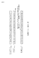
図8は、インプリメンテーションガイドラインに紹介されている、P1、及び、P2のSignalling、並びに、OFDM信号の周波数オフセットを考慮した一連の復調シーケンスを説明する図である。 FIG. 8 is a diagram for explaining a series of demodulation sequences in consideration of P1 and P2 Signaling and the frequency offset of the OFDM signal introduced in the implementation guidelines.
すなわち、図8は、T2フレームのシーケンスを示している。 That is, FIG. 8 shows a sequence of T2 frames.
インプリメンテーションガイドラインに記載の復調シーケンスによれば、OFDM受信装置は、動作開始時に、まず、P1を検出する(P1 detection)。 According to the demodulation sequence described in the implementation guideline, the OFDM receiver first detects P1 (P1 detection) at the start of operation.
P1の検出の後は、OFDM受信装置は、P1の「細かい」周波数オフセット補正、及び、「粗い」周波数オフセット補正を行う。 After detection of P1, the OFDM receiver performs P1 “fine” frequency offset correction and “coarse” frequency offset correction.
周波数オフセット補正の後は、P1を復調すること(P1のSignallingを解くこと)(P1 demodulation)ができ、これにより、OFDM受信装置は、P2、データ(NORMAL)、及び、FCのFFTサイズを認識することができる。 After frequency offset correction, P1 can be demodulated (P1 Signaling can be solved) (P1 demodulation), so that the OFDM receiver can recognize P2, data (NORMAL), and FC FFT size can do.
さらに、OFDM受信装置は、P1の復調によって、GI長のグループ情報を認識することができる。但し、GI長そのものは、認識することができないため、例えば、図8に示すように、T2フレームが、2個のOFDMシンボルのP2等の、複数のP2を含む場合には、先頭から2番目以降のP2の先頭の位置を特定することができない。 Further, the OFDM receiving apparatus can recognize the GI length group information by the demodulation of P1. However, since the GI length itself cannot be recognized, for example, as shown in FIG. 8, when the T2 frame includes a plurality of P2 such as P2 of two OFDM symbols, the second from the beginning. The head position of P2 thereafter cannot be specified.
その結果、OFDM信号の受信開始後、最初の(1番目の)T2フレーム(P1を復調したT2フレーム)に含まれる複数のP2の復調は、行うことができない。 As a result, demodulation of a plurality of P2 included in the first (first) T2 frame (T2 frame obtained by demodulating P1) cannot be performed after reception of the OFDM signal is started.
そのため、OFDM受信装置では、最初のT2フレームの残りのシンボルを用いて、P2の復調に必要なGI長の推定(GI estimation)を行う必要がある。 Therefore, the OFDM receiver needs to perform GI estimation necessary for P2 demodulation using the remaining symbols of the first T2 frame.
OFDM受信装置は、GI長の推定の後、次の(2番目の)T2フレームを待って、そのT2フレームのP1に続くP2を、P1から認識したFFTサイズと、最初のT2フレームから推定したGI長とを用いて抽出して復調する。 After estimating the GI length, the OFDM receiver waits for the next (second) T2 frame, and estimates P2 following P1 of the T2 frame from the FFT size recognized from P1 and the first T2 frame. Extract and demodulate using GI length.
OFDM受信装置では、P2の復調により、L1プレ、さらには、L1ポスト(図3)を取得することができ(L1PRE decoding (and L1POST decoding))、そのL1プレ、及び、L1ポストの情報を用いて、データ(Normal)、及び、FCを復調することができる。 The OFDM receiver can acquire the L1 pre and further the L1 post (FIG. 3) by the demodulation of P2 (L1PRE decoding (and L1POST decoding)), and use the information of the L1 pre and the L1 post. Thus, data (Normal) and FC can be demodulated.
以上の、インプリメンテーションガイドラインに紹介されている復調シーケンスでは、最初のT2フレームにおいて、GI長の推定のために、P2を復調することができず、その結果、データ(FCを含む)の復調が、T2フレームの1フレーム分だけ遅延する。 In the demodulation sequence introduced in the above implementation guidelines, P2 cannot be demodulated in order to estimate the GI length in the first T2 frame. As a result, data (including FC) is demodulated. Is delayed by one frame of the T2 frame.
そこで、OFDM受信装置において、P2(のL1プレ)、又は、データ(FCを含む)の復調に必要な正確な値の伝送パラメータをあらかじめ用意しておき、そのあらかじめ用意した伝送パラメータ(以下、プリセットともいう)を用いて、復調を行うことを考える。 Therefore, in the OFDM receiver, prepare transmission parameters with the exact values necessary for demodulation of P2 (L1 pre) or data (including FC) in advance, and then prepare the transmission parameters (hereinafter referred to as preset). It is also considered to perform demodulation using (also referred to as).
なお、プリセットは、例えば、OFDM受信装置が搭載されるTV(テレビジョン受像機)等の購入後の初期設定で行われる、いわゆるチャンネルスキャン等において、そのTVが受信可能なチャンネルについて取得する。 Note that the preset is acquired for a channel that can be received by the TV, for example, in a so-called channel scan performed in an initial setting after purchase of a TV (television receiver) or the like on which the OFDM receiver is mounted.
TVが受信可能なチャンネルについてのプリセットの取得は、例えば、インターネット等のネットワークからダウンロードすることや、TVが内蔵するメモリに、各チャンネルのプリセットを記憶させておき、そのメモリから、プリセットを読み出すこと等によって行うことができる。 To obtain presets for channels that can be received by the TV, for example, download from a network such as the Internet, or store presets for each channel in the TV's built-in memory, and read the presets from that memory. Etc.
ここで、データ(FCを含む)の復調に必要な伝送パラメータは、FFTサイズ、MISO又はSISOを表す伝送方式、GI長、パイロットパターン(PP)、伝送帯域の拡張の有無(BWT_EXT)、及び、1つのT2フレームに含まれるOFDMシンボルの数(NDSYM)である。 Here, the transmission parameters necessary for demodulating data (including FC) are FFT size, transmission method representing MISO or SISO, GI length, pilot pattern (PP), presence / absence of transmission band extension (BWT_EXT), and This is the number of OFDM symbols (NDSYM) included in one T2 frame.
また、P2(のL1プレ)の復調に必要な伝送パラメータは、FFTサイズ、伝送方式、及び、GI長である。 Further, transmission parameters necessary for demodulation of P2 (L1 pre) are FFT size, transmission method, and GI length.
なお、FFTサイズ、及び、伝送方式は、P1から認識することができるので、プリセットとしては、上述した必要な伝送パラメータのうちの、少なくとも、FFTサイズ、及び、伝送方式を除く伝送パラメータがあれば良い。 Since the FFT size and transmission method can be recognized from P1, the preset has at least transmission parameters other than the FFT size and transmission method as described above. good.
プリセットとして、例えば、P2(のL1プレ)の復調に必要な伝送パラメータを用意しておく場合には、OFDM受信装置では、プリセットを用いて、P2(のL1プレ)を復調し、その復調の結果得られる、パイロットパターン(PP)、伝送帯域の拡張の有無(BWT_EXT)、及び、1つのT2フレームに含まれるOFDMシンボルの数(NDSYM)をもさらに用いることで、データ(FCを含む)を復調することができる。 For example, when the transmission parameters necessary for demodulation of P2 (L1 pre) are prepared as presets, the OFDM receiver uses the preset to demodulate P2 (L1 pre) and perform the demodulation. By further using the resulting pilot pattern (PP), transmission band extension presence / absence (BWT_EXT), and the number of OFDM symbols (NDSYM) included in one T2 frame, data (including FC) can be used. It can be demodulated.
図9は、プリセットを用いたOFDM信号の復調を説明する図である。 FIG. 9 is a diagram for explaining demodulation of an OFDM signal using a preset.
図9Aは、FFTサイズが16K及び32K以外のT2フレームのシーケンスを示している。 FIG. 9A shows a sequence of T2 frames having FFT sizes other than 16K and 32K.
FFTサイズが16K及び32K以外のT2フレームには、1つ(1OFDMシンボル)以上のP2が含まれる。 A T2 frame whose FFT size is other than 16K and 32K includes one (1 OFDM symbol) or more P2s.
プリセットを用いる場合、OFDM受信装置は、最初のT2フレームのP1を検出し(P1 detection)、そのP1を復調する(P1 demodulation)。 When using the preset, the OFDM receiver detects P1 of the first T2 frame (P1 detection) and demodulates the P1 (P1 demodulation).
また、OFDM受信装置は、プリセットとしてのGI長等を用いて、最初のT2フレームのP2を抽出して復調し、P2の復調により得られるL1プレ、さらには、L1ポストの情報を用いて、データ(Normal)、及び、FCを復調する。 In addition, the OFDM receiver uses the GI length as a preset to extract and demodulate P2 of the first T2 frame, and use the L1 pre, which is obtained by the demodulation of P2, and the information of the L1 post, Data (Normal) and FC are demodulated.
以上のように、プリセットを用いる場合には、最初のT2フレームから、データ(FCを含む)の復調を行うこと、つまり、プリセットを用いない図8の場合と比較して、(T2フレームの)1フレーム分だけ、迅速に、データ(FCを含む)の復調を行うことができる。 As described above, when a preset is used, data (including FC) is demodulated from the first T2 frame, that is, compared with the case of FIG. Data (including FC) can be demodulated quickly for one frame.
図9Bは、FFTサイズが16K又は32KのT2フレームのシーケンスを示している。 FIG. 9B shows a T2 frame sequence with an FFT size of 16K or 32K.
FFTサイズが16K又は32KのT2フレームには、P2は、1OFDMシンボルしか含まれない(ので、2番目以降のP2の先頭を特定する必要がない)。 In a T2 frame with an FFT size of 16K or 32K, P2 contains only 1 OFDM symbol (so there is no need to specify the beginning of the second and subsequent P2).
したがって、FFTサイズが16K又は32Kである場合には、プリセットとして、GI長が用意されていなくても、P2を復調することができる。 Therefore, when the FFT size is 16K or 32K, P2 can be demodulated even if the GI length is not prepared as a preset.
その結果、やはり、図9Aの場合と同様に、最初のT2フレームから、データ(FCを含む)の復調を行うことができる。 As a result, as in the case of FIG. 9A, data (including FC) can be demodulated from the first T2 frame.
ところで、OFDM信号に、「粗い」周波数オフセットが存在する場合には、P1を用いて、「粗い」周波数オフセットを推定し、その推定値を検出する「粗い」周波数オフセット検出では、図7で説明したように、オフセット量offsetの最小値MINから最大値MAXまでの検出レンジの複数のオフセット量offsetそれぞれについて、P1の先頭から、オフセット量offsetだけずれたずらし位置を始点とする既知位置のサブキャリアのパワーの総和を求めるため、P1を用いた「粗い」周波数オフセット検出に時間を要する。 By the way, in the case of “coarse” frequency offset detection in which a “coarse” frequency offset exists in the OFDM signal, P1 is used to estimate the “coarse” frequency offset and detect the estimated value. As described above, for each of a plurality of offset amounts offset in the detection range from the minimum value MIN to the maximum value MAX of the offset amount offset, a subcarrier at a known position starting from a shift position shifted from the head of P1 by the offset amount offset. It takes time to detect the “coarse” frequency offset using P1.
図2の従来のOFDM受信装置では、P1を用いた「粗い」周波数オフセット検出に時間を要する場合には、その間に、P1に続くP2が、周波数オフセット補正部11を通過し、P2について、「粗い」周波数オフセット補正を行うことができないため、同期が確立せず、P2を正確に復調することが困難となる。
In the conventional OFDM receiver of FIG. 2, when “coarse” frequency offset detection using P1 takes time, P2 following P1 passes through the frequency offset
すなわち、図10は、OFDM信号に、「粗い」周波数オフセットが存在する場合の、プリセットを用いたOFDM信号の復調を説明する図である。 That is, FIG. 10 is a diagram for explaining demodulation of an OFDM signal using a preset when a “coarse” frequency offset exists in the OFDM signal.
なお、図10Aは、FFTサイズが16K及び32K以外のT2フレームのシーケンスを示し、図10Bは、FFTサイズが16K及び32KのT2フレームのシーケンスを示している。 10A shows a sequence of T2 frames having an FFT size other than 16K and 32K, and FIG. 10B shows a sequence of T2 frames having an FFT size of 16K and 32K.
OFDM信号に、「粗い」周波数オフセットが存在する場合には、図2の従来のOFDM受信装置では、最初のT2フレームのP1を用いた「粗い」周波数オフセット検出(Coarse Carrier Offset estimation)を行っている間に、そのP1に続くP2が、周波数オフセット補正部11を通過し、P2について、「粗い」周波数オフセット補正を行うことができないため、同期が確立せず、P2を正確に復調することが困難となる。
When a “coarse” frequency offset exists in the OFDM signal, the conventional OFDM receiver of FIG. 2 performs “coarse carrier offset estimation” using P1 of the first T2 frame. In the meantime, P2 following P1 passes through the frequency offset
その結果、図2のOFDM受信装置では、次のT2フレームを待って、そのT2フレームのP1に続くP2を復調し、その後に、データ(FCを含む)を復調することになる。 As a result, the OFDM receiving apparatus in FIG. 2 waits for the next T2 frame, demodulates P2 following P1 of the T2 frame, and then demodulates data (including FC).
したがって、図2のOFDM受信装置では、プリセットを用いても、OFDM信号に、「粗い」周波数オフセットが存在する場合には、最初のT2フレームにおいて、P2を復調することができず、その結果、データ(FCを含む)の復調が、T2フレームの1フレーム分だけ遅延する。 Therefore, in the OFDM receiver of FIG. 2, even if a preset is used, if a “coarse” frequency offset exists in the OFDM signal, P2 cannot be demodulated in the first T2 frame, and as a result, Demodulation of data (including FC) is delayed by one T2 frame.
そこで、図5のOFDM受信装置では、周波数領域周波数オフセット補正部23が、FFT演算部22において、OFDM時間領域信号のFFT演算が行われることによって得られるOFDM周波数領域信号を対象として、P1を用いて検出された「粗い」周波数オフセットの推定値に従い、「粗い」周波数オフセット補正を行う。
5, the frequency domain frequency offset
そして、FFT演算部22は、プリアンブル処理部25が、最初のT2フレームのP1を用いた「粗い」周波数オフセット検出を行うのと並列して、そのP1に続くP2を対象としたFFT演算を行う。
Then, in parallel with the fact that the
したがって、FFT演算部22において、最初のT2フレームのP2のFFT演算が行われている間に、プリアンブル処理部25による、最初のT2フレームのP1を用いた「粗い」周波数オフセット検出が終了し、FFT演算部22の後段の周波数領域周波数オフセット補正部23において、FFT演算が終了した後のP2、つまり、最初のT2フレームのP2の「粗い」周波数オフセット補正を行って、同期を確立することができる。
Therefore, while the
その結果、最初のT2フレームのP2を正確に復調することができ、そのP2の情報を用いて、データ(Normal)、及び、FCを復調すること、すなわち、最初のT2フレームから、データ(FCを含む)を、迅速に復調することができる。 As a result, P2 of the first T2 frame can be accurately demodulated, and data (Normal) and FC are demodulated using the information of P2, that is, from the first T2 frame, data (FC Can be demodulated quickly.
図11は、OFDM信号に、「粗い」周波数オフセットが存在する場合の、図5のOFDM受信装置によるOFDM信号の復調を説明する図である。 FIG. 11 is a diagram for explaining demodulation of an OFDM signal by the OFDM receiver of FIG. 5 when a “coarse” frequency offset is present in the OFDM signal.
なお、図11Aは、FFTサイズが16K及び32K以外のT2フレームのシーケンスを示し、図11Bは、FFTサイズが16K及び32KのT2フレームのシーケンスを示している。 Note that FIG. 11A shows a sequence of T2 frames with FFT sizes other than 16K and 32K, and FIG. 11B shows a sequence of T2 frames with FFT sizes of 16K and 32K.
図5のOFDM受信装置では、FFT演算部22において、最初のT2フレームのP2のFFT演算が行われている間に、プリアンブル処理部25において、最初のT2フレームのP1を用いた「粗い」周波数オフセット検出(Coarse Carrier Offset estimation)が行われ、「粗い」周波数オフセットの推定値が検出される。
In the OFDM receiver of FIG. 5, while the
そして、最初のT2フレームのP2のFFT演算の終了後、FFT演算部22の後段の周波数領域周波数オフセット補正部23において、FFT演算が終了した後の最初のT2フレームのP2の「粗い」周波数オフセット補正が行われる。
Then, after the FFT calculation of P2 in the first T2 frame is completed, the “rough” frequency offset of P2 in the first T2 frame after the FFT calculation is completed in the frequency domain frequency offset
ここで、図5のOFDM受信装置は、OFDM信号の受信を開始した後の最初のT2フレームを処理するときには、P2(及び、データ(FCを含む))の復調に必要な伝送パラメータとしては、プリセットを使用する。 Here, when the OFDM receiving apparatus of FIG. 5 processes the first T2 frame after the reception of the OFDM signal is started, transmission parameters necessary for demodulation of P2 (and data (including FC)) are as follows: Use presets.
なお、図5のOFDM受信装置では、P1から認識されるFFTサイズが、16Kか、32Kである場合において、P2(及び、データ(FCを含む))の復調に必要な伝送パラメータのうちのGI長が、プリセットとして用意されていないときには、GI長としては、0、又は、DVB-T2で規定されているGI長の最小の値である1/128を使用する。 In the OFDM receiver of FIG. 5, when the FFT size recognized from P1 is 16K or 32K, GI of transmission parameters necessary for demodulation of P2 (and data (including FC)) When the length is not prepared as a preset, 0 is used as the GI length, or 1/128, which is the minimum value of the GI length defined by DVB-T2.
但し、復調に必要な伝送パラメータのうちのGI長として、0、又は、DVB-T2で規定されているGI長の最小の値である1/128を使用する場合には、このGI長は、正確な値ではないため、最初のT2フレームについては、GI長の推定を行う必要があり、さらに、「粗い」周波数オフセットに起因する、OFDM周波数信号のIQコンスタレーション上での回転を、回転部24(図5)で補正することが困難となる。 However, in the case of using 0 or 1/128 which is the minimum value of the GI length defined in DVB-T2 as the GI length of transmission parameters necessary for demodulation, this GI length is Since it is not an accurate value, it is necessary to estimate the GI length for the first T2 frame, and the rotation of the OFDM frequency signal on the IQ constellation due to the `` coarse '' frequency offset 24 (FIG. 5) is difficult to correct.
この場合、「粗い」周波数オフセットに起因する、OFDM周波数信号の回転については、回転部24の後段で行われる等化で対応することになる。
In this case, the rotation of the OFDM frequency signal due to the “coarse” frequency offset is handled by equalization performed after the
[周波数オフセット補正] [Frequency offset correction]
図12は、図5の周波数領域周波数オフセット補正部23による「粗い」周波数オフセット補正を説明する図である。
FIG. 12 is a diagram for explaining the “coarse” frequency offset correction by the frequency domain frequency offset
図5で説明したように、FFT演算部22は、OFDMシンボルを構成するサブキャリアc#iの集合について、周波数の低い方からj+1番目(j=0,1,・・・)のサブキャリアc#iのキャリアインデクスを、j(=i+K)として、そのキャリアインデクスjを、j+1番目のサブキャリアに対応付けて、OFDMシンボルを構成するサブキャリアc#iの集合としての複数のサブキャリアc#iの並びとともに、周波数領域周波数オフセット補正部23に供給する。
As described in FIG. 5, the
OFDM信号に、+Kだけの「粗い」周波数オフセットが存在する場合、FFT演算部22で得られるOFDM時間領域信号であるOFDMシンボルを構成するサブキャリアc#iは、そのサブキャリアc#i(の本来)の設定周波数f#iから、+K個のサブキャリア間隔だけずれた設定周波数f#jに近い位置に存在し、その結果、FFT演算部22において、本来のキャリアインデクスiではないキャリアインデクスj=i+Kと対応付けられる。
When a “coarse” frequency offset of only + K exists in the OFDM signal, the subcarrier c # i constituting the OFDM symbol that is the OFDM time domain signal obtained by the
周波数領域周波数オフセット補正部23では、プリアンブル処理部25からの「粗い」周波数オフセットの推定値に従って、サブキャリアc#iに対応付けられているキャリアインデクスを、本来のキャリアインデクスiではないキャリアインデクスjから、本来のキャリアインデクスiに変更(補正)することが、「粗い」周波数オフセット補正として行われる。
The frequency domain frequency offset
図12は、FFT演算部22で得られるOFDMシンボルを構成するサブキャリアc#iの集合としての複数のサブキャリアc#iの並び(FFT出力データ)、及び、サブキャリアc#iに対応付けられたキャリアインデクスjと、「粗い」周波数オフセット補正後のキャリアインデクス(補正後キャリアインデクス)とを示している。
FIG. 12 shows an arrangement (FFT output data) of a plurality of subcarriers c # i as a set of subcarriers c # i constituting an OFDM symbol obtained by the
プリアンブル処理部25からの「粗い」周波数オフセットの推定値が、例えば、+10である場合、周波数領域周波数オフセット補正部23では、FFT演算部22で得られるOFDMシンボルを構成するサブキャリアc#iに対応付けられたキャリアインデクスjが、そのキャリアインデクスjを-10だけしたキャリアインデクスi(=j-10)に変更される。
When the estimated value of the “coarse” frequency offset from the
[検出レンジ設定処理] [Detection range setting processing]
図13は、図5のプリアンブル処理部25による検出レンジ設定処理を説明するフローチャートである。
FIG. 13 is a flowchart for explaining detection range setting processing by the
ここで、図5のOFDM受信装置では、図11で説明したように、FFT演算部22において、最初のT2フレームのP2のFFT演算を行っている間に、プリアンブル処理部25において、最初のT2フレームのP1を用いた「粗い」周波数オフセット検出を行い、「粗い」周波数オフセットの推定値を検出する。
Here, in the OFDM receiver of FIG. 5, as described with reference to FIG. 11, while the
そして、最初のT2フレームのP2のFFT演算の終了後、FFT演算部22の後段の周波数領域周波数オフセット補正部23において、FFT演算が終了した後の最初のT2フレームのP2の「粗い」周波数オフセット補正を行う。
Then, after the FFT calculation of P2 in the first T2 frame is completed, the “rough” frequency offset of P2 in the first T2 frame after the FFT calculation is completed in the frequency domain frequency offset
このように、周波数オフセット補正部23において、FFT演算が終了した後の最初のT2フレームのP2の「粗い」周波数オフセット補正を行うには、プリアンブル処理部25による、最初のT2フレームのP1を用いた「粗い」周波数オフセット検出が終了した以後に、FFT演算部22において、最初のT2フレームのP2のFFT演算が終了する必要がある。
Thus, in order to perform “coarse” frequency offset correction of P2 of the first T2 frame after the FFT operation is completed in the frequency offset
しかしながら、P2のFFTサイズが、例えば、1Kや2K等のように、小さいサイズである場合には、FFT演算部22でのP2のFFT演算に要する時間が短時間で済み、P2のFFT演算が、早期に終了する。
However, when the FFT size of P2 is a small size such as 1K or 2K, for example, the time required for the FFT calculation of P2 in the
そして、プリアンブル処理部25において、最初のT2フレームのP1を用いた「粗い」周波数オフセット検出が終了する前に、FFT演算部22において、最初のT2フレームのP2のFFT演算が終了してしまうと、周波数領域周波数オフセット補正部23において、「粗い」周波数オフセットの推定値に従った、最初のT2フレームのP2の「粗い」周波数オフセット補正を行うことができないことになる。
When the
そこで、FFT演算部22の前段、又は、後段に、データを遅延するためのメモリを設け、そのメモリで、データの遅延を行うことによって、プリアンブル処理部25での、最初のT2フレームのP1を用いた「粗い」周波数オフセット検出が終了してから、FFT演算が終了した後の最初のT2フレームのP2を、FFT演算部22から周波数領域周波数オフセット補正部23に供給する方法がある。
Therefore, a memory for delaying data is provided at the front stage or the rear stage of the
しかしながら、この方法では、メモリを設けるために、OFDM受信装置が、大型化するとともに、高コスト化することになる。 However, in this method, since the memory is provided, the OFDM receiving apparatus is increased in size and cost.
一方、プリアンブル処理部25では、「粗い」周波数オフセット検出において、上述したように、オフセット量offsetの最小値MINから、オフセット量offsetの最大値MAXまでの範囲である検出レンジの複数のオフセット量offsetそれぞれについて、P1の先頭から、オフセット量offsetだけずれたずらし位置を始点とする複数の位置としての既知位置のサブキャリアのパワーの総和を求める。
On the other hand, in the “coarse” frequency offset detection, the
したがって、「粗い」周波数オフセット検出には、検出レンジの広さ(幅)に比例するような時間を要するため、検出レンジを狭くすることによって、「粗い」周波数オフセット検出に要する時間を短くすることができる。 Therefore, since “coarse” frequency offset detection requires time proportional to the width (width) of the detection range, the time required for “coarse” frequency offset detection can be shortened by narrowing the detection range. Can do.
そこで、プリアンブル処理部25では、検出レンジを設定する検出レンジ設定処理を行い、必要に応じて、「粗い」周波数オフセット検出を、短時間で行うことで、FFT演算部22において、最初のT2フレームの、小さいFFTサイズのP2のFFT演算が終了する以前に、「粗い」周波数オフセット検出を終了することができるようになっている。
Therefore, the
すなわち、検出レンジ設定処理では、例えば、ユーザがチャンネルを選択すると、ステップS11において、プリアンブル処理部25は、ユーザが選択したチャンネル(注目チャンネル)について、その注目チャンネルを、前回受信したときのオフセット量offsetが、内蔵するメモリ(図示せず)に記憶されているかどうかを判定する。
That is, in the detection range setting process, for example, when the user selects a channel, in step S11, the
ここで、検出レンジ設定処理では、後述するステップS14において、あるチャンネルを受信したときに、「粗い」周波数オフセット検出で検出された「粗い」周波数オフセットとしてのオフセット量offsetを、そのチャンネルと対応付けて、プリアンブル処理部25が内蔵するメモリに記憶するようになっている。
Here, in the detection range setting process, in step S14 described later, when a certain channel is received, the offset amount offset as the “coarse” frequency offset detected by the “coarse” frequency offset detection is associated with the channel. Thus, it is stored in a memory built in the
ステップS11において、注目チャンネルについてのオフセット量offsetがメモリに記憶されていないと判定された場合、処理は、ステップS12に進み、プリアンブル処理部25は、検出レンジとして、デフォルトのレンジ(デフォルトレンジ)である、広いレンジを設定し、処理は、ステップS14に進む。
If it is determined in step S11 that the offset amount offset for the channel of interest is not stored in the memory, the process proceeds to step S12, and the
ここで、デフォルトレンジとしては、例えば、DVB-T2の規格上、最も広いレンジ、すなわち、OFDM信号を送信する伝送帯域が、例えば、8MHzである場合には、前述したように、「粗い」周波数オフセット検出によって検出可能な±500kHzの範囲に相当するレンジを採用することができる。 Here, as the default range, for example, when the widest range in the DVB-T2 standard, that is, when the transmission band for transmitting the OFDM signal is 8 MHz, for example, as described above, the “rough” frequency A range corresponding to a range of ± 500 kHz that can be detected by offset detection can be employed.
一方、ステップS11において、注目チャンネルについてのオフセット量offsetがメモリに記憶されていると判定された場合、処理は、ステップS13に進み、プリアンブル処理部25は、メモリに記憶された注目チャンネルについてのオフセット量offset(前回の注目チャンネルの受信時に、「粗い」周波数オフセット検出で検出された「粗い」周波数オフセットの推定値としてのオフセット量offset)を含む、デフォルトレンジよりも狭いレンジを、検出レンジとして設定し、処理は、ステップS14に進む。
On the other hand, when it is determined in step S11 that the offset amount offset for the channel of interest is stored in the memory, the process proceeds to step S13, and the
ここで、注目チャンネルの「粗い」周波数オフセットは、受信環境が大きく変化しない限り、前回の注目チャンネルの受信時と、今回の注目チャンネルの受信時とで、それほど変化しないと考えられる。 Here, it is considered that the “coarse” frequency offset of the channel of interest does not change so much between the reception of the previous channel of interest and the reception of the current channel of interest unless the reception environment changes greatly.
したがって、注目チャンネルについてのオフセット量offsetがメモリに記憶されている場合、すなわち、前回の注目チャンネルの受信時に、「粗い」周波数オフセット検出で検出された「粗い」周波数オフセットの推定値としてのオフセット量offsetが、メモリに記憶されている場合には、その前回の受信時の推定値を含む、その推定値付近の狭い範囲を、検出レンジとして設定しても、「粗い」周波数オフセット検出を、正確に行うことができる。 Therefore, when the offset amount offset for the channel of interest is stored in the memory, that is, the offset amount as an estimated value of the “coarse” frequency offset detected by the “coarse” frequency offset detection at the time of reception of the previous channel of interest. If offset is stored in the memory, even if a narrow range near the estimated value including the estimated value at the time of the previous reception is set as the detection range, the “coarse” frequency offset detection is accurately performed. Can be done.
そして、検出レンジを、狭い範囲に設定することにより、「粗い」周波数オフセット検出に要する時間を短くすることができ、プリアンブル処理部25において、最初のT2フレームのP1を用いた「粗い」周波数オフセット検出が終了する前に、FFT演算部22において、最初のT2フレームのP2のFFT演算が終了することを防止することができる。
Then, by setting the detection range to a narrow range, the time required for detecting the “coarse” frequency offset can be shortened. In the
ステップS14では、例えば、ユーザが、チャンネルを変更することや、電源をオフにすること等によって、注目チャンネルの受信が終了するのを待って、プリアンブル処理部25は、例えば、その受信の終了の直前に、P1を用いた「粗い」周波数オフセット検出で検出された「粗い」周波数オフセットの推定値としてのオフセット量offsetを、注目チャンネルと対応付けて、メモリに記憶して(注目チャンネルの前回の受信時のオフセット量offsetが記憶されている場合には、上書きして)、検出レンジ設定処理を終了する。 In step S14, for example, the user waits for the reception of the channel of interest to end by changing the channel or turning off the power. Immediately before, the offset amount offset as an estimated value of the “coarse” frequency offset detected by the “coarse” frequency offset detection using P1 is stored in the memory in association with the channel of interest (the previous channel of the channel of interest). If the offset amount offset at the time of reception is stored, it is overwritten), and the detection range setting process is terminated.
なお、図13では、ユーザが、チャンネルを選択するごとに、そのチャンネル(注目チャンネル)について、その受信の終了の直前に、P1を用いた「粗い」周波数オフセット検出で検出された「粗い」周波数オフセットの推定値としてのオフセット量offsetを、メモリに記憶するが、チャンネルについての、「粗い」周波数オフセットの推定値としてのオフセット量offsetの、メモリへの記憶は、例えば、そのチャンネルが、最初に選択されたときだけ行うことができる。 In FIG. 13, every time the user selects a channel, the “coarse” frequency detected by the “coarse” frequency offset detection using P1 for the channel (the channel of interest) immediately before the end of reception. The offset amount offset as an estimate of the offset is stored in the memory, but the offset amount offset as an estimate of the “coarse” frequency offset for the channel is stored in the memory, for example, the channel first Can only be done when selected.
<第2実施の形態> <Second Embodiment>
図14は、本発明を適用した、OFDM受信装置として機能する信号処理装置の第2実施の形態の構成例を示すブロック図である。 FIG. 14 is a block diagram illustrating a configuration example of a second embodiment of a signal processing device functioning as an OFDM receiving device to which the present invention has been applied.
なお、図中、図5の場合と対応する部分については、同一の符号を付してあり、以下では、その説明は、適宜省略する。 In the figure, portions corresponding to those in FIG. 5 are denoted by the same reference numerals, and description thereof will be omitted as appropriate.
すなわち、図14のOFDM受信装置は、時間領域周波数オフセット補正部21ないしシンボル同期部26を含む点で、図5の場合と共通し、チャネル干渉除去部31、シンボル数カウント部41、周波数オフセット補正制御部42、及び、演算部43が新たに設けられている点で、図5の場合と相違する。
That is, the OFDM receiver of FIG. 14 is common to the case of FIG. 5 in that it includes a time domain frequency offset
OFDM受信装置には、アナログ放送を受信するTV等のように、チャネル(伝送路)干渉を除去する機能を、OFDM時間領域信号を処理する系に設けることができる。 The OFDM receiver can be provided with a function for removing channel (transmission path) interference in a system that processes OFDM time domain signals, such as a TV that receives analog broadcasting.
この場合、ある指定された周波数帯域のOFDM時間領域信号を対象としたフィルタリング等の、チャネル干渉の除去の処理(チャネル干渉除去処理)を行うときに、そのチャネル干渉除去処理が行われるOFDM時間領域信号について、周波数オフセット補正が行われている必要がある。 In this case, when performing channel interference removal processing (channel interference removal processing) such as filtering for an OFDM time domain signal in a specified frequency band, the OFDM time domain in which the channel interference removal processing is performed The signal needs to be subjected to frequency offset correction.
そこで、図14のOFDM受信装置では、最初のT2フレームについては、「粗い」周波数オフセット補正を、FFT演算部22の後段の周波数領域周波数オフセット補正部23で行い、2番目以降のT2フレームについては、OFDM時間領域信号を対象として、「細かい」周波数オフセット補正を行う時間領域周波数オフセット補正部21において、「粗い」周波数オフセット補正をも行うようになっている。
Therefore, in the OFDM receiver of FIG. 14, for the first T2 frame, “coarse” frequency offset correction is performed by the frequency domain frequency offset
すなわち、図14のOFDM受信装置では、チャネル干渉除去部31には、時間領域周波数オフセット補正部21が出力するOFDM時間領域信号が供給される。
That is, in the OFDM receiver of FIG. 14, the channel
チャネル干渉除去部31は、時間領域周波数オフセット補正部21からのOFDM時間領域信号に、チャネル干渉除去処理を施し、FFT演算部22に供給する。
The channel
シンボル数カウント部41には、シンボル同期部26から、FFTトリガ情報が供給される。
The symbol count counting unit 41 is supplied with FFT trigger information from the
シンボル数カウント部41は、シンボル同期部26からのFFTトリガ情報の数をカウントし、そのカウント値が、T2フレームの1フレームに含まれるOFDMシンボルの数となると、T2フレームの終端のタイミングであることを表すフレーム終端フラグを、周波数オフセット補正制御部42に供給する。
The symbol count unit 41 counts the number of FFT trigger information from the
周波数オフセット補正制御部42には、シンボル数カウント部41から、フレーム終端フラグが供給される他、プリアンブル処理部25から、P1を用いた「粗い」周波数オフセット検出によって検出された「粗い」周波数オフセットの推定値(オフセット量offset)が供給される。
The frequency offset
周波数オフセット補正制御部42は、OFDM信号の受信の開始後、シンボル数カウント部41からフレーム終端フラグが供給されるまでは、つまり、最初のT2フレームの処理が行われている間は、プリアンブル処理部25からの「粗い」周波数オフセットの推定値を、周波数領域周波数オフセット補正部23、及び、回転部24に供給するとともに、「粗い」周波数オフセットの推定値としての0を、演算部43に供給する。
The frequency offset
また、周波数オフセット補正制御部42は、OFDM信号の受信の開始後、シンボル数カウント部41からフレーム終端フラグが供給されると、それ以降は、つまり、2番目のT2フレームの処理が開始されてからは、プリアンブル処理部25からの「粗い」周波数オフセットの推定値を、演算部43に供給するとともに、「粗い」周波数オフセットの推定値としての0を、周波数領域周波数オフセット補正部23、及び、回転部24に供給する。
Further, when the frame end flag is supplied from the symbol number counting unit 41 after the reception of the OFDM signal is started, the frequency offset
演算部43には、周波数オフセット補正制御部42から、「粗い」周波数オフセットの推定値が供給される他、プリアンブル処理部25から、P1を用いた「細かい」周波数オフセット検出(P1を用いて「細かい」周波数オフセットを推定し、その推定値を検出すること)によって検出された「細かい」周波数オフセットの推定値が供給される。
The calculation unit 43 is supplied with an estimated value of the “coarse” frequency offset from the frequency offset
演算部43は、周波数オフセット補正制御部42からの「粗い」周波数オフセットの推定値と、プリアンブル処理部25からの「細かい」周波数オフセットの推定値とを加算し、その加算結果としての、周波数オフセットの推定値を、時間領域周波数オフセット補正部21に供給する。
The computing unit 43 adds the estimated value of the “coarse” frequency offset from the frequency offset
以上のように構成されるOFDM受信装置では、周波数オフセット補正制御部42は、OFDM信号の受信の開始後、シンボル数カウント部41からフレーム終端フラグが供給されるまでは、つまり、最初のT2フレームの処理が行われている間は、プリアンブル処理部25からの「粗い」周波数オフセットの推定値を、周波数領域周波数オフセット補正部23、及び、回転部24に供給するとともに、「粗い」周波数オフセットの推定値としての0を、演算部43に供給する。
In the OFDM receiver configured as described above, the frequency offset
したがって、周波数領域周波数オフセット補正部23、及び、回転部24では、最初のT2フレームについては、周波数オフセット補正制御部42から供給される、プリアンブル処理部25で検出された「粗い」周波数オフセットの推定値を用いて、図5のOFDM受信装置と同様の処理が行われる。
Therefore, the frequency domain frequency offset
また、演算部43では、周波数オフセット補正制御部42からの、「粗い」周波数オフセットの推定値である0と、プリアンブル処理部25からの「細かい」周波数オフセットの推定値とが加算され、その加算結果としての、周波数オフセットの推定値、すなわち、いまの場合、プリアンブル処理部25からの「細かい」周波数オフセットの推定値が、時間領域周波数オフセット補正部21に供給される。
In addition, the calculation unit 43 adds the estimated value of “coarse” frequency offset 0 from the frequency offset
したがって、時間領域周波数オフセット補正部21では、最初のT2フレームについては、プリアンブル処理部25で検出された「細かい」周波数オフセットの推定値を用いて、図5のOFDM受信装置と同様の処理が行われる。
Therefore, the time domain frequency offset
その後、周波数オフセット補正制御部42は、OFDM信号の受信の開始後、シンボル数カウント部41からフレーム終端フラグが供給されると、それ以降は、つまり、2番目のT2フレームの処理が開始されてからは、プリアンブル処理部25からの「粗い」周波数オフセットの推定値を、演算部43に供給するとともに、「粗い」周波数オフセットの推定値としての0を、周波数領域周波数オフセット補正部23、及び、回転部24に供給する。
Thereafter, when the frame end flag is supplied from the symbol count counting unit 41 after the reception of the OFDM signal is started, the frequency offset
したがって、周波数領域周波数オフセット補正部23、及び、回転部24では、2番目以降のT2フレームについては、周波数オフセット補正制御部42から供給される、「粗い」周波数オフセットの推定値としての0を用いて、処理が行われる。
Therefore, the frequency domain frequency offset
すなわち、この場合、周波数領域周波数オフセット補正部23、及び、回転部24では、実質的に、処理は行われず、OFDM周波数領域信号は、周波数領域周波数オフセット補正部23、及び、回転部24を通過(バイパス)する。
That is, in this case, the frequency domain frequency offset
また、演算部43では、周波数オフセット補正制御部42からの、プリアンブル処理部25で検出された「粗い」周波数オフセットの推定値と、プリアンブル処理部25からの「細かい」周波数オフセットの推定値とが加算され、その加算結果としての、周波数オフセットの推定値が、時間領域周波数オフセット補正部21に供給される。
In addition, in the calculation unit 43, the estimated value of the “coarse” frequency offset detected by the
したがって、時間領域周波数オフセット補正部21では、2番目以降のT2フレームについては、周波数オフセット補正制御部42から供給される、プリアンブル処理部25で検出された「粗い」周波数オフセットの推定値、及び、「細かい」周波数オフセットの推定値との加算結果に従い、OFDM時間領域信号の、「粗い」周波数オフセット補正、及び、「細かい」周波数オフセット補正が同時に(区別なく)施される。
Therefore, in the time domain frequency offset
以上、本発明を、DVB-T2に準拠したOFDM信号を処理する信号処理装置としてのOFDM受信装置に適用した場合について説明したが、本発明は、その他、データの復調に必要な情報がシグナリングされたプリアンブル信号である、第1のプリアンブル信号と、第1のプリアンブル信号に続く第2のプリアンブル信号とを含むOFDM信号を処理する信号処理装置に適用可能である。 As described above, the case where the present invention is applied to an OFDM receiving apparatus as a signal processing apparatus that processes an OFDM signal compliant with DVB-T2 has been described. However, the present invention signals other information necessary for data demodulation. The present invention can be applied to a signal processing apparatus that processes an OFDM signal including a first preamble signal that is a preamble signal and a second preamble signal that follows the first preamble signal.
そして、かかる信号処理装置は、例えば、テレビジョン放送を受信するTVや、チューナ、録画装置等に適用することができる。 Such a signal processing device can be applied to, for example, a TV that receives television broadcasts, a tuner, a recording device, and the like.
[本発明を適用したコンピュータの説明] [Description of Computer to which the Present Invention is Applied]
次に、上述した一連の処理は、ハードウェアにより行うこともできるし、ソフトウェアにより行うこともできる。一連の処理をソフトウェアによって行う場合には、そのソフトウェアを構成するプログラムが、汎用のコンピュータ等にインストールされる。 Next, the series of processes described above can be performed by hardware or software. When a series of processing is performed by software, a program constituting the software is installed in a general-purpose computer or the like.
そこで、図15は、上述した一連の処理を実行するプログラムがインストールされるコンピュータの一実施の形態の構成例を示している。 Accordingly, FIG. 15 shows a configuration example of an embodiment of a computer in which a program for executing the series of processes described above is installed.
プログラムは、コンピュータに内蔵されている記録媒体としてのハードディスク105やROM103に予め記録しておくことができる。
The program can be recorded in advance on a
あるいはまた、プログラムは、リムーバブル記録媒体111に格納(記録)しておくことができる。このようなリムーバブル記録媒体111は、いわゆるパッケージソフトウエアとして提供することができる。ここで、リムーバブル記録媒体111としては、例えば、フレキシブルディスク、CD-ROM(Compact Disc Read Only Memory),MO(Magneto Optical)ディスク,DVD(Digital Versatile Disc)、磁気ディスク、半導体メモリ等がある。
Alternatively, the program can be stored (recorded) in the
なお、プログラムは、上述したようなリムーバブル記録媒体111からコンピュータにインストールする他、通信網や放送網を介して、コンピュータにダウンロードし、内蔵するハードディスク105にインストールすることができる。すなわち、プログラムは、例えば、ダウンロードサイトから、ディジタル衛星放送用の人工衛星を介して、コンピュータに無線で転送したり、LAN(Local Area Network)、インターネットといったネットワークを介して、コンピュータに有線で転送することができる。
In addition to installing the program from the
コンピュータは、CPU(Central Processing Unit)102を内蔵しており、CPU102には、バス101を介して、入出力インタフェース110が接続されている。
The computer incorporates a CPU (Central Processing Unit) 102, and an input /
CPU102は、入出力インタフェース110を介して、ユーザによって、入力部107が操作等されることにより指令が入力されると、それに従って、ROM(Read Only Memory)103に格納されているプログラムを実行する。あるいは、CPU102は、ハードディスク105に格納されたプログラムを、RAM(Random Access Memory)104にロードして実行する。
The
これにより、CPU102は、上述したフローチャートにしたがった処理、あるいは上述したブロック図の構成により行われる処理を行う。そして、CPU102は、その処理結果を、必要に応じて、例えば、入出力インタフェース110を介して、出力部106から出力、あるいは、通信部108から送信、さらには、ハードディスク105に記録等させる。
Thus, the
なお、入力部107は、キーボードや、マウス、マイク等で構成される。また、出力部106は、LCD(Liquid Crystal Display)やスピーカ等で構成される。
The
ここで、本明細書において、コンピュータがプログラムに従って行う処理は、必ずしもフローチャートとして記載された順序に沿って時系列に行われる必要はない。すなわち、コンピュータがプログラムに従って行う処理は、並列的あるいは個別に実行される処理(例えば、並列処理あるいはオブジェクトによる処理)も含む。 Here, in the present specification, the processing performed by the computer according to the program does not necessarily have to be performed in time series in the order described as the flowchart. That is, the processing performed by the computer according to the program includes processing executed in parallel or individually (for example, parallel processing or object processing).
また、プログラムは、1のコンピュータ(プロセッサ)により処理されるものであっても良いし、複数のコンピュータによって分散処理されるものであっても良い。さらに、プログラムは、遠方のコンピュータに転送されて実行されるものであっても良い。 Further, the program may be processed by one computer (processor) or may be distributedly processed by a plurality of computers. Furthermore, the program may be transferred to a remote computer and executed.
なお、本発明の実施の形態は、上述した実施の形態に限定されるものではなく、本発明の要旨を逸脱しない範囲において種々の変更が可能である。 The embodiment of the present invention is not limited to the above-described embodiment, and various modifications can be made without departing from the gist of the present invention.
11 周波数オフセット補正部, 12 FFT演算部, 13 時間領域周波数オフセット検出部, 14 周波数領域周波数オフセット検出部, 15 周波数オフセット補正量推定部, 21 時間領域周波数オフセット補正部, 22 FFT演算部, 23 周波数領域周波数オフセット補正部, 24 回転部, 25 プリアンブル処理部, 26 シンボル同期部, 31 チャネル干渉除去部, 41 シンボル数カウント部, 42 周波数オフセット補正制御部, 43 演算部, 101 バス, 102 CPU, 103 ROM, 104 RAM, 105 ハードディスク, 106 出力部, 107 入力部, 108 通信部, 109 ドライブ, 110 入出力インタフェース, 111 リムーバブル記録媒体 11 frequency offset correction unit, 12 FFT calculation unit, 13 time domain frequency offset detection unit, 14 frequency domain frequency offset detection unit, 15 frequency offset correction amount estimation unit, 21 time domain frequency offset correction unit, 22 FFT calculation unit, 23 frequency Domain frequency offset correction unit, 24 rotation unit, 25 preamble processing unit, 26 symbol synchronization unit, 31 channel interference cancellation unit, 41 symbol number counting unit, 42 frequency offset correction control unit, 43 arithmetic unit, 101 bus, 102 CPU, 103 ROM, 104 RAM, 105 hard disk, 106 output unit, 107 input unit, 108 communication unit, 109 drive, 110 input / output interface, 111 removable recording medium
Claims (4)
前記OFDM信号を復調するときに用いられるキャリアの誤差である周波数オフセットの推定値を検出する周波数オフセット検出を行う処理手段と、
前記周波数領域のOFDM信号を対象として、前記周波数オフセットの推定値に従い、前記周波数オフセットを補正する周波数オフセット補正を行う周波数オフセット補正手段と
を備え、
前記OFDM信号は、第1のプリアンブル信号と、前記第1のプリアンブル信号に続く第2のプリアンブル信号とを含み、
前記演算手段は、前記処理手段が前記第1のプリアンブル信号を用いた前記周波数オフセット検出を行うのと並列して、前記第2のプリアンブル信号を対象とした前記変換演算を行う
信号処理装置。 An arithmetic means for performing a transform operation for Fourier transforming an OFDM (Orthogonal Frequency Division Multiplexing) signal in the time domain to an OFDM signal in the frequency domain;
Processing means for performing frequency offset detection for detecting an estimated value of a frequency offset which is an error of a carrier used when demodulating the OFDM signal;
Frequency offset correction means for performing frequency offset correction for correcting the frequency offset according to the estimated value of the frequency offset for the OFDM signal in the frequency domain,
The OFDM signal includes a first preamble signal and a second preamble signal following the first preamble signal;
The signal processing apparatus, wherein the calculation means performs the conversion calculation on the second preamble signal in parallel with the processing means performing the frequency offset detection using the first preamble signal.
所定のサブキャリア数分の周波数オフセットを表すオフセット量の最小値から、前記オフセット量の最大値までの範囲である検出レンジの複数の前記オフセット量それぞれについて、前記第1のプリアンブル信号の先頭から、前記オフセット量だけずれたずらし位置を始点とする所定の複数の位置のサブキャリアの総和を求め、
複数の前記オフセット量それぞれについて得られる前記サブキャリアの総和の中の、大きさが最大の総和を検出し、前記最大の総和に対応する前記オフセット量を、前記周波数オフセットの推定値として検出し、
前記周波数オフセットの推定値を、その推定値を検出した前記OFDM信号のチャンネルと対応付けて記憶し、
前記周波数オフセットの推定値が記憶されていないチャンネルの前記OFDM信号を受信する場合、前記周波数オフセット検出で用いる検出レンジとして、デフォルトのレンジであるデフォルトレンジを設定し、
前記周波数オフセットの推定値が記憶されているチャンネルの前記OFDM信号を受信する場合、前記検出レンジとして、前記チャンネルと対応付けられている推定値を含む、前記デフォルトレンジよりも狭いレンジを設定する
請求項1に記載の信号処理装置。 The processing means includes
From the beginning of the first preamble signal for each of the plurality of offset amounts of the detection range that is a range from the minimum value of the offset amount representing the frequency offset for the predetermined number of subcarriers to the maximum value of the offset amount, Obtaining a sum of subcarriers at a plurality of predetermined positions starting from a shifted position shifted by the offset amount;
Among the sum of the subcarriers obtained for each of the plurality of offset amounts, the sum having the maximum size is detected, and the offset amount corresponding to the maximum sum is detected as an estimated value of the frequency offset,
Storing the estimated value of the frequency offset in association with the channel of the OFDM signal from which the estimated value is detected;
When receiving the OFDM signal of a channel in which the estimated value of the frequency offset is not stored, a default range that is a default range is set as a detection range used in the frequency offset detection
When receiving the OFDM signal of a channel in which the estimated value of the frequency offset is stored, a range narrower than the default range including the estimated value associated with the channel is set as the detection range. Item 2. The signal processing device according to Item 1.
前記OFDM信号は、1つの前記第1のプリアンブル信号と、1つ以上の前記第2のプリアンブル信号とを含むフレーム単位で伝送され、
前記OFDM信号の受信を開始してから、最初のフレームについては、前記周波数オフセット補正手段で周波数オフセット補正を行い、その後のフレームについては、前記他の周波数オフセット補正手段で周波数オフセット補正を行う
請求項1に記載の信号処理装置。 Other frequency offset correction means for performing frequency offset correction for correcting the frequency offset according to the estimated value of the frequency offset for the OFDM signal in the time domain,
The OFDM signal is transmitted in frame units including one of the first preamble signals and one or more of the second preamble signals,
The frequency offset correction is performed by the frequency offset correction unit for the first frame after the reception of the OFDM signal is started, and the frequency offset correction is performed by the other frequency offset correction unit for the subsequent frames. 2. The signal processing apparatus according to 1.
時間領域のOFDM(Orthogonal Frequency Division Multiplexing)信号を、周波数領域のOFDM信号にフーリエ変換する変換演算を行う演算ステップと、
前記OFDM信号を復調するときに用いられるキャリアの誤差である周波数オフセットの推定値を検出する周波数オフセット検出を行う処理ステップと、
前記周波数領域のOFDM信号を対象として、前記周波数オフセットの推定値に従い、前記周波数オフセットを補正する周波数オフセット補正を行う周波数オフセット補正ステップと
を含み、
前記OFDM信号は、第1のプリアンブル信号と、前記第1のプリアンブル信号に続く第2のプリアンブル信号とを含み、
前記演算ステップでは、前記処理ステップにおいて前記第1のプリアンブル信号を用いた前記周波数オフセット検出を行うのと並列して、前記第2のプリアンブル信号を対象とした前記変換演算を行う
信号処理方法。 The signal processor
An operation step for performing a transform operation for Fourier transforming a time domain OFDM (Orthogonal Frequency Division Multiplexing) signal to an OFDM signal in the frequency domain,
A processing step of performing frequency offset detection for detecting an estimated value of a frequency offset which is an error of a carrier used when demodulating the OFDM signal;
A frequency offset correction step for performing frequency offset correction for correcting the frequency offset according to the estimated value of the frequency offset for the OFDM signal in the frequency domain, and
The OFDM signal includes a first preamble signal and a second preamble signal following the first preamble signal;
In the calculation step, the conversion calculation for the second preamble signal is performed in parallel with the frequency offset detection using the first preamble signal in the processing step.
Priority Applications (7)
| Application Number | Priority Date | Filing Date | Title |
|---|---|---|---|
| JP2009173591A JP5267874B2 (en) | 2009-07-24 | 2009-07-24 | Signal processing apparatus and signal processing method |
| TW099122672A TWI410071B (en) | 2009-07-24 | 2010-07-09 | Signal processing apparatus and method |
| EP10168996.6A EP2278768A3 (en) | 2009-07-24 | 2010-07-09 | Apparatus and method for carrier frequency synchronization in an OFDM system |
| US12/836,893 US8374264B2 (en) | 2009-07-24 | 2010-07-15 | Signal processing apparatus and method |
| RU2010129532/07A RU2549205C2 (en) | 2009-07-24 | 2010-07-15 | Signal processing apparatus and method |
| BRPI1004961-4A BRPI1004961A2 (en) | 2009-07-24 | 2010-07-16 | Signal Processing Apparatus and Method |
| CN2010102334314A CN101964772B (en) | 2009-07-24 | 2010-07-19 | Signal processing apparatus and method |
Applications Claiming Priority (1)
| Application Number | Priority Date | Filing Date | Title |
|---|---|---|---|
| JP2009173591A JP5267874B2 (en) | 2009-07-24 | 2009-07-24 | Signal processing apparatus and signal processing method |
Publications (3)
| Publication Number | Publication Date |
|---|---|
| JP2011029921A JP2011029921A (en) | 2011-02-10 |
| JP2011029921A5 JP2011029921A5 (en) | 2012-08-16 |
| JP5267874B2 true JP5267874B2 (en) | 2013-08-21 |
Family
ID=42565083
Family Applications (1)
| Application Number | Title | Priority Date | Filing Date |
|---|---|---|---|
| JP2009173591A Expired - Fee Related JP5267874B2 (en) | 2009-07-24 | 2009-07-24 | Signal processing apparatus and signal processing method |
Country Status (7)
| Country | Link |
|---|---|
| US (1) | US8374264B2 (en) |
| EP (1) | EP2278768A3 (en) |
| JP (1) | JP5267874B2 (en) |
| CN (1) | CN101964772B (en) |
| BR (1) | BRPI1004961A2 (en) |
| RU (1) | RU2549205C2 (en) |
| TW (1) | TWI410071B (en) |
Families Citing this family (25)
| Publication number | Priority date | Publication date | Assignee | Title |
|---|---|---|---|---|
| JP5497800B2 (en) * | 2009-03-06 | 2014-05-21 | テレフオンアクチーボラゲット エル エム エリクソン(パブル) | Method and apparatus for compensating for carrier frequency offset in orthogonal frequency division multiplexing wireless communication system |
| US9325438B2 (en) * | 2010-11-17 | 2016-04-26 | Lg Electronics Inc. | Broadcast-signal transmitter/receiver and method for transmitting/receiving broadcast signals |
| US8532228B2 (en) * | 2010-12-23 | 2013-09-10 | Microchip Technology Incorporated | Automatic frequency offset compensation in zero-intermediate frequency receivers using minimum-shift keying (MSK) signaling |
| US8548096B2 (en) * | 2010-12-31 | 2013-10-01 | Telefonaktiebolaget L M Ericsson (Publ) | Controllable frequency offset for inphase and Quadrature (IQ) imbalance estimation |
| US20130296653A1 (en) * | 2011-01-22 | 2013-11-07 | Intermountain Invention Management, Llc | Apparatus, systems, and methods for accessing the airway with medical instruments without interruption of assisted respiration |
| US8837611B2 (en) * | 2011-02-09 | 2014-09-16 | Silicon Laboratories Inc. | Memory-aided synchronization in a receiver |
| JP2012191565A (en) * | 2011-03-14 | 2012-10-04 | Sony Corp | Receiver, reception method, and program |
| FR2973616B1 (en) * | 2011-04-01 | 2013-11-01 | St Microelectronics Grenoble 2 | SYSTEM AND METHOD FOR DEMODULATING SYMBOLS OF A DIGITAL TERRESTRIAL TELEVISION SIGNAL |
| CN103095627B (en) * | 2011-10-28 | 2016-12-07 | 中国移动通信集团广东有限公司 | A kind of orthogonal frequency division multiplexi system synchronization method and electronic equipment |
| FR2989242A1 (en) | 2012-04-10 | 2013-10-11 | France Telecom | PROCESS FOR PROCESSING RECEIVED MULTI-CARRIER SIGNAL, METHOD FOR RECEIVING OPTICAL SIGNAL, COMPUTER PROGRAM, AND CORRESPONDING PROCESSING DEVICE |
| JP5983996B2 (en) * | 2012-05-31 | 2016-09-06 | ソニー株式会社 | Receiving apparatus and receiving method |
| CN103546797B (en) * | 2012-07-11 | 2017-03-15 | 扬智电子科技(上海)有限公司 | Receiving system and its method |
| US9385909B2 (en) * | 2013-10-08 | 2016-07-05 | Freescale Semiconductor, Inc. | Detecting repeated preamble symbols using over-sized discrete fourier transforms |
| CN105791179B (en) * | 2014-12-18 | 2019-03-29 | 联芯科技有限公司 | Sampling frequency offset compensation device and method |
| CN104618276B (en) * | 2014-12-23 | 2018-07-03 | 大唐半导体设计有限公司 | Carrier frequency bias estimation and system in a kind of FM receiver |
| US10091731B2 (en) * | 2016-02-05 | 2018-10-02 | Samsung Electronics Co., Ltd. | Method and apparatus for detecting packet |
| JP7046805B2 (en) * | 2016-07-08 | 2022-04-04 | ソニーセミコンダクタソリューションズ株式会社 | Transmission device and transmission method |
| KR102601201B1 (en) * | 2016-10-07 | 2023-11-13 | 한국전자통신연구원 | Frequency offset estimation and compensation method |
| CN106571854A (en) * | 2016-11-05 | 2017-04-19 | 北京晓程科技股份有限公司 | Power carrier OFDM (orthogonal frequency division multiplexing) system frequency domain frame detection synchronization method and device |
| RU2680971C1 (en) * | 2017-01-09 | 2019-03-01 | Федеральное государственное бюджетное образовательное учреждение высшего образования "Казанский национальный исследовательский технический университет им. А.Н. Туполева-КАИ" (КНИТУ-КАИ) | Method for processing ofdm signals and device therefor |
| US10541852B2 (en) * | 2017-11-23 | 2020-01-21 | Nxp Usa, Inc. | Preamble detection mechanism for reception of asynchronous packets |
| MX2020013236A (en) | 2018-06-06 | 2021-02-22 | Massachusetts Inst Technology | Circular rna for translation in eukaryotic cells. |
| US10135660B1 (en) * | 2018-06-12 | 2018-11-20 | Hong Kong Applied Science and Technology Research Institute Company Limited | Sampling frequency offset tracking based on decision feedback channel estimation |
| BR112021023411A2 (en) | 2019-05-22 | 2022-02-01 | Massachusetts Inst Technology | Compositions and methods of circular rna |
| MX2022006854A (en) | 2019-12-04 | 2022-11-30 | Orna Therapeutics Inc | Circular rna compositions and methods. |
Family Cites Families (14)
| Publication number | Priority date | Publication date | Assignee | Title |
|---|---|---|---|---|
| US6618452B1 (en) * | 1998-06-08 | 2003-09-09 | Telefonaktiebolaget Lm Ericsson (Publ) | Burst carrier frequency synchronization and iterative frequency-domain frame synchronization for OFDM |
| RU2221284C2 (en) * | 2002-02-26 | 2004-01-10 | Дочернее государственное унитарное научно-исследовательское предприятие "АРГУС" | Coded speech transmission and reception method |
| KR100555722B1 (en) * | 2003-05-20 | 2006-03-03 | 삼성전자주식회사 | Integer frequency offset estimator of multi carrier receiver and a method integer frequency offset estimating thereof |
| EP1507378B1 (en) * | 2003-08-14 | 2012-10-24 | Sony Deutschland GmbH | Frame and frequency synchronization for OFDM |
| WO2005101711A1 (en) * | 2004-04-14 | 2005-10-27 | Matsushita Electric Industrial Co., Ltd. | Reception device |
| KR100720546B1 (en) * | 2004-12-17 | 2007-05-22 | 엘지전자 주식회사 | Method and Apparatus for synchronization acquisition in Digital receiver |
| JP4153916B2 (en) * | 2005-01-31 | 2008-09-24 | 株式会社東芝 | Wireless communication device |
| CN1835493A (en) * | 2006-04-18 | 2006-09-20 | 杭州电子科技大学 | Method of obtaining orthogonal frequency division complex signal timing synchronization |
| JP4983365B2 (en) * | 2006-05-16 | 2012-07-25 | ソニー株式会社 | Wireless communication device |
| CN101079688B (en) * | 2006-05-23 | 2010-09-01 | 中兴通讯股份有限公司 | A synchronization method in orthogonal frequency division multiplexing system |
| GB2449470B (en) * | 2007-05-23 | 2011-06-29 | British Broadcasting Corp | OFDM-MIMO radio frequency transmission system |
| WO2008149263A2 (en) * | 2007-06-04 | 2008-12-11 | Nokia Corporation | System and method for scheduling and transferring data through a transmission system |
| US8208522B2 (en) * | 2008-03-07 | 2012-06-26 | Nokia Corporation | System and methods for receiving OFDM symbols having timing and frequency offsets |
| JP5347792B2 (en) * | 2009-07-16 | 2013-11-20 | ソニー株式会社 | Signal processing apparatus, signal processing method, and reception system |
-
2009
- 2009-07-24 JP JP2009173591A patent/JP5267874B2/en not_active Expired - Fee Related
-
2010
- 2010-07-09 TW TW099122672A patent/TWI410071B/en not_active IP Right Cessation
- 2010-07-09 EP EP10168996.6A patent/EP2278768A3/en not_active Withdrawn
- 2010-07-15 RU RU2010129532/07A patent/RU2549205C2/en not_active IP Right Cessation
- 2010-07-15 US US12/836,893 patent/US8374264B2/en not_active Expired - Fee Related
- 2010-07-16 BR BRPI1004961-4A patent/BRPI1004961A2/en not_active Application Discontinuation
- 2010-07-19 CN CN2010102334314A patent/CN101964772B/en not_active Expired - Fee Related
Also Published As
| Publication number | Publication date |
|---|---|
| RU2010129532A (en) | 2012-01-20 |
| US20110019782A1 (en) | 2011-01-27 |
| TW201119273A (en) | 2011-06-01 |
| BRPI1004961A2 (en) | 2015-03-17 |
| TWI410071B (en) | 2013-09-21 |
| US8374264B2 (en) | 2013-02-12 |
| EP2278768A2 (en) | 2011-01-26 |
| CN101964772A (en) | 2011-02-02 |
| RU2549205C2 (en) | 2015-04-20 |
| EP2278768A3 (en) | 2016-03-02 |
| JP2011029921A (en) | 2011-02-10 |
| CN101964772B (en) | 2013-10-23 |
Similar Documents
| Publication | Publication Date | Title |
|---|---|---|
| JP5267874B2 (en) | Signal processing apparatus and signal processing method | |
| JP5294030B2 (en) | Receiving apparatus and method, and program | |
| US8406322B2 (en) | OFDM demodulation device and method | |
| JP5347792B2 (en) | Signal processing apparatus, signal processing method, and reception system | |
| JP5577884B2 (en) | Reception device, reception method, and reception system | |
| JP5493803B2 (en) | Receiving apparatus and method, program, and receiving system | |
| JP6319638B2 (en) | Receiving device, receiving method, and program | |
| JP4465797B2 (en) | Receiving apparatus and receiving method | |
| JP2010087744A (en) | Reception device, reception method, and program | |
| JP5712698B2 (en) | Signal processing apparatus, signal processing method, and program | |
| JP2007202082A (en) | Ofdm demodulating device and method | |
| JP3757144B2 (en) | OFDM receiving apparatus and OFDM signal receiving method | |
| TWI246271B (en) | Boundary tracking method and related apparatus for an OFDM receiver | |
| JP3793534B2 (en) | OFDM receiving apparatus and OFDM signal receiving method | |
| JP5460579B2 (en) | Linear error phase correction method and apparatus for orthogonal frequency division multiplexed signal | |
| JP2010087749A (en) | Receiving device and method, and program | |
| JP2009284436A (en) | Ofdm receiving apparatus | |
| JP2004096187A (en) | Digital broadcast receiver |
Legal Events
| Date | Code | Title | Description |
|---|---|---|---|
| A521 | Written amendment |
Free format text: JAPANESE INTERMEDIATE CODE: A523 Effective date: 20120704 |
|
| A621 | Written request for application examination |
Free format text: JAPANESE INTERMEDIATE CODE: A621 Effective date: 20120704 |
|
| A977 | Report on retrieval |
Free format text: JAPANESE INTERMEDIATE CODE: A971007 Effective date: 20130315 |
|
| TRDD | Decision of grant or rejection written | ||
| A01 | Written decision to grant a patent or to grant a registration (utility model) |
Free format text: JAPANESE INTERMEDIATE CODE: A01 Effective date: 20130411 |
|
| A61 | First payment of annual fees (during grant procedure) |
Free format text: JAPANESE INTERMEDIATE CODE: A61 Effective date: 20130424 |
|
| R151 | Written notification of patent or utility model registration |
Ref document number: 5267874 Country of ref document: JP Free format text: JAPANESE INTERMEDIATE CODE: R151 |
|
| R250 | Receipt of annual fees |
Free format text: JAPANESE INTERMEDIATE CODE: R250 |
|
| R250 | Receipt of annual fees |
Free format text: JAPANESE INTERMEDIATE CODE: R250 |
|
| R250 | Receipt of annual fees |
Free format text: JAPANESE INTERMEDIATE CODE: R250 |
|
| R250 | Receipt of annual fees |
Free format text: JAPANESE INTERMEDIATE CODE: R250 |
|
| LAPS | Cancellation because of no payment of annual fees |