JP5267617B2 - Analysis apparatus and analysis method - Google Patents
Analysis apparatus and analysis method Download PDFInfo
- Publication number
- JP5267617B2 JP5267617B2 JP2011139400A JP2011139400A JP5267617B2 JP 5267617 B2 JP5267617 B2 JP 5267617B2 JP 2011139400 A JP2011139400 A JP 2011139400A JP 2011139400 A JP2011139400 A JP 2011139400A JP 5267617 B2 JP5267617 B2 JP 5267617B2
- Authority
- JP
- Japan
- Prior art keywords
- region
- reaction
- test substance
- analysis
- background
- Prior art date
- Legal status (The legal status is an assumption and is not a legal conclusion. Google has not performed a legal analysis and makes no representation as to the accuracy of the status listed.)
- Expired - Fee Related
Links
- 238000004458 analytical method Methods 0.000 title claims abstract description 71
- 238000012360 testing method Methods 0.000 claims abstract description 138
- 239000000126 substance Substances 0.000 claims abstract description 72
- 238000001514 detection method Methods 0.000 claims abstract description 42
- 238000003384 imaging method Methods 0.000 claims description 64
- 238000000034 method Methods 0.000 claims description 41
- 238000005259 measurement Methods 0.000 claims description 12
- 230000000007 visual effect Effects 0.000 claims description 9
- 238000011161 development Methods 0.000 description 8
- 238000005286 illumination Methods 0.000 description 8
- 238000011088 calibration curve Methods 0.000 description 7
- 238000003317 immunochromatography Methods 0.000 description 7
- 230000003287 optical effect Effects 0.000 description 7
- 238000012545 processing Methods 0.000 description 7
- 230000035484 reaction time Effects 0.000 description 7
- 210000004369 blood Anatomy 0.000 description 6
- 239000008280 blood Substances 0.000 description 6
- 238000012123 point-of-care testing Methods 0.000 description 5
- 230000006870 function Effects 0.000 description 4
- 230000005856 abnormality Effects 0.000 description 3
- 230000003321 amplification Effects 0.000 description 3
- 210000000805 cytoplasm Anatomy 0.000 description 3
- 210000003743 erythrocyte Anatomy 0.000 description 3
- 238000010191 image analysis Methods 0.000 description 3
- 238000003780 insertion Methods 0.000 description 3
- 230000037431 insertion Effects 0.000 description 3
- 230000002452 interceptive effect Effects 0.000 description 3
- 239000008267 milk Substances 0.000 description 3
- 210000004080 milk Anatomy 0.000 description 3
- 235000013336 milk Nutrition 0.000 description 3
- 238000003199 nucleic acid amplification method Methods 0.000 description 3
- 238000010586 diagram Methods 0.000 description 2
- 239000007788 liquid Substances 0.000 description 2
- 238000011002 quantification Methods 0.000 description 2
- 239000004065 semiconductor Substances 0.000 description 2
- 210000002700 urine Anatomy 0.000 description 2
- 102000001554 Hemoglobins Human genes 0.000 description 1
- 108010054147 Hemoglobins Proteins 0.000 description 1
- 230000002159 abnormal effect Effects 0.000 description 1
- 239000000427 antigen Substances 0.000 description 1
- 102000036639 antigens Human genes 0.000 description 1
- 108091007433 antigens Proteins 0.000 description 1
- 210000004027 cell Anatomy 0.000 description 1
- 239000003153 chemical reaction reagent Substances 0.000 description 1
- 238000004587 chromatography analysis Methods 0.000 description 1
- 238000004040 coloring Methods 0.000 description 1
- 230000000295 complement effect Effects 0.000 description 1
- 238000001739 density measurement Methods 0.000 description 1
- PCHJSUWPFVWCPO-UHFFFAOYSA-N gold Chemical compound [Au] PCHJSUWPFVWCPO-UHFFFAOYSA-N 0.000 description 1
- 230000001900 immune effect Effects 0.000 description 1
- 229910044991 metal oxide Inorganic materials 0.000 description 1
- 150000004706 metal oxides Chemical class 0.000 description 1
- 238000004445 quantitative analysis Methods 0.000 description 1
- 230000004044 response Effects 0.000 description 1
- 230000035945 sensitivity Effects 0.000 description 1
- 238000000926 separation method Methods 0.000 description 1
Images


Classifications
-
- G—PHYSICS
- G01—MEASURING; TESTING
- G01N—INVESTIGATING OR ANALYSING MATERIALS BY DETERMINING THEIR CHEMICAL OR PHYSICAL PROPERTIES
- G01N33/00—Investigating or analysing materials by specific methods not covered by groups G01N1/00 - G01N31/00
- G01N33/48—Biological material, e.g. blood, urine; Haemocytometers
- G01N33/50—Chemical analysis of biological material, e.g. blood, urine; Testing involving biospecific ligand binding methods; Immunological testing
- G01N33/53—Immunoassay; Biospecific binding assay; Materials therefor
- G01N33/543—Immunoassay; Biospecific binding assay; Materials therefor with an insoluble carrier for immobilising immunochemicals
-
- G—PHYSICS
- G01—MEASURING; TESTING
- G01N—INVESTIGATING OR ANALYSING MATERIALS BY DETERMINING THEIR CHEMICAL OR PHYSICAL PROPERTIES
- G01N33/00—Investigating or analysing materials by specific methods not covered by groups G01N1/00 - G01N31/00
- G01N33/48—Biological material, e.g. blood, urine; Haemocytometers
- G01N33/483—Physical analysis of biological material
- G01N33/487—Physical analysis of biological material of liquid biological material
- G01N33/4875—Details of handling test elements, e.g. dispensing or storage, not specific to a particular test method
- G01N33/48771—Coding of information, e.g. calibration data, lot number
-
- G—PHYSICS
- G01—MEASURING; TESTING
- G01N—INVESTIGATING OR ANALYSING MATERIALS BY DETERMINING THEIR CHEMICAL OR PHYSICAL PROPERTIES
- G01N21/00—Investigating or analysing materials by the use of optical means, i.e. using sub-millimetre waves, infrared, visible or ultraviolet light
- G01N21/75—Systems in which material is subjected to a chemical reaction, the progress or the result of the reaction being investigated
- G01N21/77—Systems in which material is subjected to a chemical reaction, the progress or the result of the reaction being investigated by observing the effect on a chemical indicator
- G01N21/78—Systems in which material is subjected to a chemical reaction, the progress or the result of the reaction being investigated by observing the effect on a chemical indicator producing a change of colour
-
- G—PHYSICS
- G01—MEASURING; TESTING
- G01N—INVESTIGATING OR ANALYSING MATERIALS BY DETERMINING THEIR CHEMICAL OR PHYSICAL PROPERTIES
- G01N21/00—Investigating or analysing materials by the use of optical means, i.e. using sub-millimetre waves, infrared, visible or ultraviolet light
- G01N21/75—Systems in which material is subjected to a chemical reaction, the progress or the result of the reaction being investigated
-
- G—PHYSICS
- G01—MEASURING; TESTING
- G01N—INVESTIGATING OR ANALYSING MATERIALS BY DETERMINING THEIR CHEMICAL OR PHYSICAL PROPERTIES
- G01N21/00—Investigating or analysing materials by the use of optical means, i.e. using sub-millimetre waves, infrared, visible or ultraviolet light
- G01N21/84—Systems specially adapted for particular applications
- G01N21/8483—Investigating reagent band
-
- G—PHYSICS
- G06—COMPUTING; CALCULATING OR COUNTING
- G06T—IMAGE DATA PROCESSING OR GENERATION, IN GENERAL
- G06T7/00—Image analysis
Landscapes
- Health & Medical Sciences (AREA)
- Life Sciences & Earth Sciences (AREA)
- Engineering & Computer Science (AREA)
- Physics & Mathematics (AREA)
- Chemical & Material Sciences (AREA)
- Immunology (AREA)
- General Physics & Mathematics (AREA)
- Pathology (AREA)
- General Health & Medical Sciences (AREA)
- Analytical Chemistry (AREA)
- Biochemistry (AREA)
- Biomedical Technology (AREA)
- Molecular Biology (AREA)
- Urology & Nephrology (AREA)
- Hematology (AREA)
- Chemical Kinetics & Catalysis (AREA)
- Plasma & Fusion (AREA)
- Food Science & Technology (AREA)
- Medicinal Chemistry (AREA)
- Optics & Photonics (AREA)
- Biophysics (AREA)
- Microbiology (AREA)
- Cell Biology (AREA)
- Biotechnology (AREA)
- Computer Vision & Pattern Recognition (AREA)
- Theoretical Computer Science (AREA)
- Investigating Or Analysing Materials By The Use Of Chemical Reactions (AREA)
Abstract
Description
本発明は、例えば、イムノクロマトグラフィ法を利用した被検物質の検出または定量に用いられる分析装置および分析方法に関する。 The present invention relates to an analysis apparatus and an analysis method used for detection or quantification of a test substance using, for example, an immunochromatography method.
近年、例えば診察室や病棟などの「患者の近いところ」で行われるポイントオブケア検査(POCT)の手法として、イムノクロマトグラフィ法(免疫学的クロマトグラフィ法)が注目されている。このようなPOCTにおいて用いられるイムノクロマトグラフィ試験片(ストリップ)は、試薬の調整を必要とせず、血液や尿などの被検査液を当該試験片上に滴下するなどの簡単な操作のみでその中の被検物質を分析することが可能であり、被検査液中の被検物質を簡便かつ迅速に分析するのに非常に有用であるため、現在多数のものが実用化されている。 In recent years, an immunochromatography method (immunological chromatography method) has attracted attention as a point-of-care test (POCT) method performed in a “patient vicinity” such as an examination room or a ward. The immunochromatographic test strip (strip) used in such POCT does not require reagent adjustment, and only a simple operation such as dropping a test liquid such as blood or urine onto the test strip can be used. Since it is possible to analyze a test substance and it is very useful for analyzing a test substance in a test liquid simply and quickly, a large number are currently put into practical use.
このようなイムノクロマトグラフィ法を用いたPOCT用の分析装置としては、例えば、検体中の被検物質によって呈色反応を生ずる反応領域を有する試験片における当該反応領域に光源からの光を照射し、試験片からの散乱光(または透過光や反射光の場合もある)を適宜の光学系を通してCCDなどからなるイメージセンサに結像させ、イメージセンサの各画素にて得られる光の光量を画素の輝度に変換して分析することにより、検体中の被検物質の濃度を定量化する構成のものが提案されている(特許文献1参照。)。 As an analyzer for POCT using such an immunochromatography method, for example, light from a light source is irradiated to the reaction region in a test piece having a reaction region that causes a color reaction by a test substance in a specimen, Scattered light (or transmitted light or reflected light in some cases) from the specimen is imaged on an image sensor such as a CCD through an appropriate optical system, and the amount of light obtained at each pixel of the image sensor A configuration has been proposed in which the concentration of a test substance in a specimen is quantified by converting it into luminance and analyzing it (see Patent Document 1).
而して、イムノクロマトグラフィ法を用いたPOCT用の分析装置においては、煩雑な操作を要さず短時間で信頼性の高い測定を行うことのできるものが求められている。
しかしながら、上記のような分析装置においては、信頼性の高い測定(分析)結果を確実に得ることができない、という問題がある。この理由は、以下に示すとおりである。
例えば、検体が血液である場合においては、赤血球が破損して、赤血球内部の原形質が細胞外に漏出することがあり、このような場合には、原形質が被検物質による呈色状態を示す反応領域に重なってしまう。従って、取得される画像データにおける、反応領域に係る画像データ部分とバックグラウンド領域に係る画像データ部分とのコントラストが、被検物質による呈色反応によって生じた呈色だけでなく、原形質の色味も混ざったものとなり、呈色状態そのものに異常が生じている可能性が高いものとなる。
また、血液中に乳糜(にゅうび)が混ざることがあるが、このような場合においても、反応領域における呈色状態が乳糜の影響を受けることとなる。なお、乳糜は、尿にも混ざることがあり、検体が血液の場合と同様の問題を生ずる。
以上のように、検体に不所望な物質(妨害物質)が混ざってしまうと、反応領域における呈色状態が目的に沿ったものでない可能性が高くなるが、上記の分析装置においては、いわば異常の生じている呈色状態に基づいて被検物質の濃度の定量化がなされ、不正確な分析結果がユーザに伝えられてしまうこととなる。
Thus, an analyzer for POCT using an immunochromatography method is required to perform a highly reliable measurement in a short time without requiring a complicated operation.
However, the analysis apparatus as described above has a problem that a highly reliable measurement (analysis) result cannot be obtained with certainty. The reason for this is as follows.
For example, when the specimen is blood, the red blood cells may be damaged, and the protoplasm inside the erythrocytes may leak out of the cell. In such a case, the protoplasm will be in a colored state by the test substance. It overlaps the reaction area shown. Therefore, in the acquired image data, the contrast between the image data portion related to the reaction region and the image data portion related to the background region is not only the color produced by the color reaction by the test substance, but also the color of the protoplasm. The taste is also mixed, and there is a high possibility that the coloration state itself is abnormal.
In addition, milky milk may be mixed in the blood. Even in such a case, the colored state in the reaction region is affected by milky milk. In addition, milk cake may be mixed with urine, and causes the same problem as when the specimen is blood.
As described above, when an undesired substance (interfering substance) is mixed in the specimen, there is a high possibility that the colored state in the reaction region is not in accordance with the purpose. Thus, the concentration of the test substance is quantified based on the coloration state in which the occurrence of the error occurs, and an inaccurate analysis result is transmitted to the user.
本発明は、以上のような事情に基づいてなされたものであって、例えばイムノクロマトグラフィ法を利用した、被検物質の検出またはその定量を高い信頼性をもって行うことのできる分析装置および分析方法を提供することを目的とする。 The present invention has been made based on the circumstances as described above. For example, an analysis apparatus and an analysis method that can perform detection or quantification of a test substance with high reliability using an immunochromatography method are provided. The purpose is to provide.
本発明の分析装置は、検体に含まれる所定の被検物質によって呈色反応を生ずる反応領域が形成された試験片における当該反応領域および当該反応領域以外のバックグラウンド領域を少なくとも視野領域に含む撮影部と、前記反応領域における呈色の程度によって前記被検物質を検出する分析部とを具えた分析装置において、
前記分析部は、前記バックグラウンド領域の状態が前記所定の被検物質の検出において被検物質の種類毎に設定された許容範囲内であるか否かを、前記撮影部によって取得された当該バックグラウンド領域に係る画像データに基づいて、判定する機能を有することを特徴とする。
The analyzer according to the present invention includes an imaging including at least a visual field region including the reaction region and a background region other than the reaction region in a test piece in which a reaction region causing a color reaction is formed by a predetermined test substance contained in a specimen. And an analyzer comprising an analyzer for detecting the test substance according to the degree of coloration in the reaction region,
The analysis unit determines whether or not the state of the background region is within an allowable range set for each type of test substance in the detection of the predetermined test substance. It has a function of determining based on image data related to the ground area.
本発明の分析装置においては、前記試験片は、前記呈色反応に関連する情報を含むコードが表示されるコード領域を前記反応領域と同一表面上に有し、当該コードが前記バックラウンド領域に係る許容範囲についての情報を含むものであり、
前記撮影部が、前記コード領域をさらに含む視野領域を有する構成のものとすることができる。
また、本発明の分析装置においては、前記バックラウンド領域に係る許容範囲についての情報が記録された記憶部を具えた構成とされていてもよい。
In the analyzer of the present invention, the test piece has a code region on the same surface as the reaction region, on which a code including information relating to the color reaction is displayed, and the code is in the background region. Including information about such tolerances,
The imaging unit may have a field of view area that further includes the code area.
Moreover, in the analyzer of this invention, you may be set as the structure provided with the memory | storage part by which the information about the tolerance | permissible_range concerning the said background area | region was recorded.
本発明の分析方法は、検体に含まれる所定の被検物質によって呈色反応を生ずる反応領域を有する試験片における当該反応領域および当該反応領域以外のバックグラウンド領域を少なくとも視野領域に含む撮影部によって、前記反応領域に係る画像データおよび前記バックグラウンド領域に係る画像データを取得し、
分析部によって、前記所定の被検物質の濃度を前記反応領域に係る画像データに基づいて算出する濃度算出処理が行われると共に、前記バックグラウンド領域の状態が前記所定の被検物質の検出において被検物質の種類毎に設定された許容範囲内であるか否かを、前記撮影部によって取得された当該バックグラウンド領域に係る画像データに基づいて、判定する判定処理が行われることを特徴とする。
The analysis method of the present invention includes an imaging unit including at least a visual field in the reaction region and a background region other than the reaction region in a test piece having a reaction region in which a color reaction is caused by a predetermined test substance contained in a specimen. , Obtaining image data relating to the reaction area and image data relating to the background area,
The analysis unit performs a concentration calculation process for calculating the concentration of the predetermined test substance based on the image data relating to the reaction area, and the state of the background area is detected in the detection of the predetermined test substance. A determination process is performed to determine whether or not a sample is within an allowable range for each type of test substance based on image data relating to the background area acquired by the imaging unit. .
また、本発明の分析方法においては、前記判定処理において前記バックグラウンド領域の状態が前記許容範囲を逸脱すると判定された場合には、前記濃度算出処理による濃度測定結果を含まないエラーメッセージ情報を分析結果として出力するエラー処理が行われる。 In the analysis method of the present invention, when it is determined in the determination process that the state of the background area is out of the allowable range, error message information not including the concentration measurement result by the concentration calculation process is analyzed. Error processing is performed as a result.
本発明の分析方法においては、前記許容範囲内において、前記反応領域における呈色が前記所定の被検物質それ自体によるものでない可能性があると判断される注意範囲がさらに設定されており、
前記判定処理において前記バックグラウンド領域の状態が前記許容範囲内において注意範囲内にあると判定された場合には、前記濃度算出処理による濃度測定結果に注意を喚起するメッセージ情報が付加されたものを分析結果として出力する注意情報付加処理が行われることが好ましい。
In the analysis method of the present invention, within the permissible range, a caution range is determined in which it is determined that the coloration in the reaction region may not be due to the predetermined test substance itself,
In the determination process, when it is determined that the state of the background area is within the caution range within the allowable range, the message information for calling attention to the concentration measurement result by the concentration calculation process is added. It is preferable to perform an attention information addition process to be output as an analysis result.
また、本発明の分析方法においては、試験片として、前記呈色反応に関連する情報を含むコードが表示されるコード領域を前記反応領域と同一表面上に有し、当該コードが前記バックラウンド領域に係る許容範囲についての情報を含むものが用いられ、
前記撮影部によって、前記反応領域および前記バックグラウンド領域並びに前記コード領域を含む分析領域についての画像データが取得されることが好ましい。
Further, in the analysis method of the present invention, the test piece has a code region on the same surface as the reaction region where a code including information related to the color reaction is displayed, and the code is the background region. Including information about tolerances for
It is preferable that image data for an analysis region including the reaction region, the background region, and the code region is acquired by the imaging unit.
本発明の分析方法によれば、試験片の反応領域における呈色が被検物質それ自体によるものか、例えば検体の異常等による妨害物質の影響を受けたものであるかを識別することができるので、検体の状態および試験片の状態が反映された分析結果を得ることができる。
上記の分析方法が実行される本発明の分析装置によれば、信頼性の高い分析結果を得ることができるので、不正確な分析結果がユーザに報知されることを回避することができる。
According to the analysis method of the present invention, it is possible to identify whether the coloration in the reaction region of the test piece is due to the test substance itself or the influence of the interfering substance due to, for example, abnormality of the specimen. Therefore, an analysis result reflecting the state of the specimen and the state of the test piece can be obtained.
According to the analysis apparatus of the present invention in which the above analysis method is executed, an analysis result with high reliability can be obtained, so that it is possible to avoid inaccurate analysis results being reported to the user.
以下、本発明の実施の形態について詳細に説明する。
本発明の分析装置は、例えばイムノクロマトグラフィ法により生体成分中の被検物質を定量分析するために用いられるものである。以下においては、先ず、本発明の分析装置において用いられるイムノクロマトグラフィ試験片について説明する。
Hereinafter, embodiments of the present invention will be described in detail.
The analyzer of the present invention is used for quantitative analysis of a test substance in a biological component by, for example, immunochromatography. In the following, first, an immunochromatographic test piece used in the analyzer of the present invention will be described.
図1は、本発明の分析装置において用いられるイムノクロマトグラフィ試験片の一例における構成の概略を示す平面図である。
このイムノクロマトグラフィ試験片(以下、単に「試験片」という。)20は、例えば濾紙などの多孔質支持体21(図1においては便宜上斜線が付してある)がケース20Aの内部に収容され、各々多孔質支持体21を外部に露出させる2箇所の開口部22A、22Bが検体の展開方向(図1において白抜きの矢印で示す。)に離間した位置に形成されて構成されている。そして、一方の開口部22Aにより検体滴下部23が構成されていると共に他方の開口部22Bにより読み取り部24が構成されている。読み取り部24においては、多孔質支持体21の、ケース20Aにおける他方の開口部22Bを介して外部に露出される表面領域に、例えば標識抗体、および、被検物質に応じた抗体または抗原が、検体の展開方向と直交する方向(図1において上下方向)に延びるライン状に固定化されており、これにより、反応領域Rが形成されている。
FIG. 1 is a plan view schematically showing the configuration of an example of an immunochromatographic test piece used in the analyzer of the present invention.
This immunochromatographic test piece (hereinafter, simply referred to as “test piece”) 20 includes a
また、この試験片20における、検体の展開方向における読み取り部24の下流側の位置には、例えばQRコード(登録商標)などの二次元コード25が設けられており、これにより、コード領域Cが形成されている。従って、この試験片20においては、反応領域Rと同一表面上にコード領域Cが形成されている。
二次元コード25に含まれる情報としては、例えば分析項目、有効期限、ロット番号などの試験片20の基本情報、および、例えば反応時間、検量線、後述するバックグラウンド領域Bの状態を判定するための判定基準となる許容範囲などの試験片20に固有の呈色反応に関連する情報などを例示することができる。
In addition, a two-
Information included in the two-
〔分析装置〕
本発明の分析装置は、試験片20における反応領域Rおよび当該反応領域R以外の他方の開口部22Bを介して外部に露出される多孔質支持体21の表面領域であるバックグラウンド領域Bを含む領域を少なくとも視野領域に含む撮影部を具えた検出部と、試験片20の反応領域Rにおける呈色の程度によって所定の被検物質を検出する分析部を具えた制御部とを具えている。
〔Analysis equipment〕
The analyzer of the present invention includes a reaction region R in the
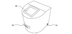
図2は、本発明の分析装置の一例における外観を示す斜視図、図3は、図2に示す分析装置の構成の概略を示すブロック図、図4は、図2に示す分析装置における検出部の構成の概略を示す斜視図である。
図2において、11は電源スイッチ、12は分析すべき検体に係るID情報などを入力すると共に動作指令信号を入力する操作手段および分析結果を表示する表示手段としてのタッチパネルである。13は試験片挿入口であって、上記構成の試験片20が、反応領域Rおよびコード領域Cを有する表面が上方を向いた状態で、水平な姿勢で挿入される。
2 is a perspective view showing an appearance of an example of the analyzer of the present invention, FIG. 3 is a block diagram showing an outline of the configuration of the analyzer shown in FIG. 2, and FIG. 4 is a detection unit in the analyzer shown in FIG. It is a perspective view which shows the outline of a structure.
In FIG. 2, 11 is a power switch, 12 is an operation means for inputting ID information relating to a sample to be analyzed and an operation command signal, and a touch panel as a display means for displaying an analysis result.
この実施の形態に係る分析装置における検出部60は、試験片20の有無を検出する試験片検出部、試験片20が適正な位置にセットされた状態において、例えば試験片20における反応領域Rおよびコード領域Cを含む分析領域を視野領域Sに含む撮影部、および、試験片20における撮影部の視野領域Sを含む領域(照明領域、図1において破線で示す。)Lを照明する照明部を具えている。
The
試験片検出部は、例えばフォトインタラプタなどの試験片検出用センサ30により構成されている。
The test piece detection unit includes a test
撮影部は、試験片20からの例えば反射光を受光して試験片20の分析領域における光強度分布像を撮影する撮影素子を具えた撮影装置40により構成されている。撮影装置40としては、例えばCMOS(Complementary Metal−Oxide Semiconductor)イメージセンサ41よりなる撮影素子を具えてなるものが用いられることが好ましい。CMOSイメージセンサ41を具えた撮影装置40が用いられることにより、例えばCCDイメージセンサにおいて生ずる「スミア」と称される撮影素子の内部で発生する電荷のオーバーフローに起因するノイズが生ずることを抑制することができるため、反応領域Rに対応する画素の出力に影響を及ぼすことはない。
The imaging unit is configured by an
照明部は、試験片20の反応領域(呈色ライン)Rの呈色濃度とのコントラストが大きくなる色光を照射する光源を具えた照明装置により構成されている。光源としては、例えばLED、半導体レーザー、ランプとバンドパスフィルターが組み合わされたものなどを用いることができるが、例えば、試験片20が標識として金コロイドが用いられたものである場合には、被検物質によって例えばピンク色に呈色することから、例えば発光ピーク波長が525nm付近にある緑色光を発するLEDが好ましい。
この実施の形態に係る分析装置においては、例えば発光素子52および当該発光素子52からの放射光の一部を受光するモニタ用の受光素子53を具えたLED51を光源として具えた照明装置50が用いられており、LED51がAPC(オートパワーコントロール)制御されることにより、周囲温度などの外乱による光量変動を抑制することができて一定の光量で安定して照明することができる。
照明装置50による照明領域Lの大きさは、例えば照明装置50の試験片20の表面に対する配置位置(離間距離)によって調整することができる。
The illuminating unit is configured by an illuminating device including a light source that irradiates color light that increases the contrast with the color density of the reaction region (coloring line) R of the
In the analysis apparatus according to this embodiment, for example, an illuminating
The magnitude | size of the illumination area L by the illuminating
制御部70は、照明装置50におけるLED51の受光素子53からの発光素子52による放射光の光量に応じた出力信号を増幅する信号増幅部71と、フィードバック制御によって、信号増幅部71で増幅された受光素子53の出力信号が一定となるよう発光素子52に対する供給電流を調整してLED51の光出力を一定とする電流制御部72と、試験片20が試験片検出用センサ30によって検出された時点からの経過時間を計測する計時部73と、撮影装置40の動作制御を行う撮影装置制御部75と、撮影装置40によって取得される画像データを分析して検体中の被検物質の濃度を算出する分析部76と、試験片20における二次元コード25に含まれる情報が書き換え可能に記録される記憶部78とを具えている。
The
撮影装置制御部75は、例えば、試験片20における分析領域について、互いに異なる第1の撮影条件および第2の撮影条件で撮影された2つの画像データが取得されるよう、撮影装置40による撮影条件を調整する機能を有する。
撮影装置40による撮影条件を調整する手法としては、例えば、撮影装置40におけるCMOSイメージセンサ41の電子シャッターのシャッタースピード(シャッター時間)を制御することにより露光時間を調整し、これにより、露光量(CMOSイメージセンサ41に受光される光の光量)を調整する方法、あるいは、照明装置50におけるLED51の発光量を制御することにより露光量を調整する方法などを用いることが好ましい。ここに、露光時間を調整して露光量を調整する方法としては、例えば、CMOSイメージセンサ41のゲイン(感度)または絞りを調整する方法もあるが、CMOSイメージセンサ41のゲインを大きくして露光量を大きくするとノイズが増え、また、絞りを変えると写り方が変化するため、CMOSイメージセンサ41の電子シャッターのシャッタースピード(シャッター時間)を制御することにより露光時間を調整する方法が望ましい。
For example, the imaging
As a method for adjusting the shooting conditions by the
撮影装置40による第1の撮影条件は、試験片20の分析領域におけるコード領域Cの撮影に最適な明るさとなるよう設定されており、具体的には例えば、2次元コード25の周辺の最も明るい箇所がCMOSイメージセンサ41の最大階調を超えないよう、CMOSイメージセンサ41の電子シャッターのシャッタースピード(露光時間)および/または照明装置50におけるLED51の発光量の大きさ、すなわちCMOSイメージセンサ41に対する露光量の大きさが設定されている。
The first imaging condition by the
撮影装置40による第2の撮影条件は、試験片20の分析領域における反応領域Rの撮影に最適な明るさとなるよう設定されており、具体的には例えば、露光量が第1の撮影条件より大きくなる条件、反応領域R(検出ラインおよびコントロールライン)以外の最も明るい箇所がCMOSイメージセンサ41の最大階調を超えない範囲内において、CMOSイメージセンサ41の電子シャッターのシャッタースピード(露光時間)および/または照明装置50におけるLED51の発光量の大きさが、第1の撮影条件より大きくなる条件に設定されている。
第2の撮影条件におけるCMOSイメージセンサ41に対する露光量は、第1の撮影条件におけるCMOSイメージセンサ41に対する露光量の例えば1.3倍程度に設定することができる。
The second imaging condition by the
The exposure amount for the
以上において、CMOSイメージセンサ41の電子シャッターのシャッタースピードの調整は、例えばCMOSカメラモジュールの動作条件を変更することにより行うことができる。
また、LED51の発光量の調整は、例えばLED51に対する供給電流の大きさを変更することにより行うことができる。
In the above, adjustment of the shutter speed of the electronic shutter of the
The light emission amount of the
分析部76は、試験片20における分析領域について第1の撮影条件で撮影された画像データ(以下、「コード読み取り画像データ」という。)に基づいて二次元コード25に含まれる当該試験片20に固有の情報を読み取る処理、および、第2の撮影条件で撮影された画像データ(以下、「被検物質検出用画像データ」という。)に基づいて反応領域Rにおける呈色部分の光学的濃度を算出する濃度算出処理を行う機能を有する。
ここに、コード読み取り画像データおよび被検物質検出用画像データは、いずれも、例えば0〜255の256階調の濃淡画像で表現されるものであって、例えば、反応領域Rおよびコード領域Cに係る最大階調部が、それぞれ、例えば200から250の範囲内であれば、コード領域Cにおいて表示される情報の読み取り、および、反応領域Rの呈色状態の読み取りを適正に行うことができる。
The
Here, both the code reading image data and the test substance detection image data are expressed by, for example, a grayscale image with 256 gradations of 0 to 255. For example, in the reaction region R and the code region C, If the maximum gradation part is within a range of 200 to 250, for example, the information displayed in the code area C and the color state of the reaction area R can be read appropriately.
而して、上記の分析装置においては、制御部70を構成する分析部76は、試験片20におけるバックグラウンド領域Bの状態が被検物質の検出において被検物質の種類毎に設定された許容範囲内であるか否かを被検物質検出用画像データにおけるバックグラウンド領域Bに係る画像データに基づいて判定する機能を有する。
具体的には、被検物質検出用画像データにおけるバックグラウンド領域Bに係る画素値を算出し、当該画素値が分析結果をタッチパネル12に表示すべき許容画素値の範囲内にあるか否かを判定する。ここに、画素値の判定基準としては、許容画素値の範囲内において、検体に不所望な物質が含まれていない場合の正常画素値の許容範囲、および、例えば、検体に不所望な物質が含まれていないものの、例えば反応領域Rにおける呈色が被検物質それ自体のものではない可能性があると判断される場合などの注意すべき場合の注意画素値の許容範囲(注意範囲)を設定することができる。許容画素値の範囲、正常画素値の許容範囲および注意画素値の許容範囲は、いずれも、実験的にあるいは経験的に設定することができる。
Thus, in the above analysis apparatus, the
Specifically, the pixel value related to the background region B in the test substance detection image data is calculated, and whether or not the pixel value is within the allowable pixel value range in which the analysis result is to be displayed on the
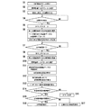
以下、上記の分析装置の動作について説明する。
分析装置の電源スイッチ11が投入されると、タッチパネル12にメニュー画面が表示されて測定可能な状態とされる。
図5に示すように、タッチパネル12において分析開始ボタンを押すと(S1)、給電装置80が作動されて制御部70に対する給電が開始され、電流制御部72によって制御された大きさの電流が発光素子52に供給されてLED51が点灯される(S2)。発光素子52に供給される電流の制御について具体的に説明すると、発光素子52からの放射光の一部が受光素子53によって受光されることにより当該受光素子53から出力される、受光強度に応じた電気信号が、信号増幅部71によって増幅されて電流制御部72に入力され、電流制御部72によって、当該電流制御部72に入力される電気信号が一定になるように、発光素子52に供給する電流の大きさが制御される。
Hereinafter, the operation of the analyzer will be described.
When the
As shown in FIG. 5, when the analysis start button is pressed on the touch panel 12 (S 1), the
そして、タッチパネル12を操作して分析すべき検体に係るID情報を入力した後(S3)、試験片20における検体滴下部23に検体を滴下して試験片20を試験片挿入口13にコード領域C側から挿入する。検出部60における試験片検出用センサ30によって試験片20がセットされたことが検出されると(S4)、試験片検出用センサ30からの試験片検出信号により計時部73が作動されてカウントが開始(タイマースタート)され(S5)、計時部73よりの動作指令信号が撮影装置制御部75に入力される。
Then, after operating the
そして、撮影装置制御部75によって、撮影装置40による撮影条件が第1の撮影条件に調整され、撮影装置40によって試験片20における分析領域が撮影されることによりコード検出用画像データが取得される。コード検出用画像データにおけるコード領域Cについて適宜の画像解析が分析部76によって行われることにより、二次元コード25に含まれた当該試験片20に固有の情報、例えば反応領域Rにおける呈色状態が検出可能となる反応時間に係る反応時間情報、検体に含まれる被検物質の濃度を算出(定量)するための検量線に係る検量線情報、バックグラウンド領域Bの状態の判定処理を行う際に用いられるバックグラウンド領域Bに係る許容画素値の範囲、正常画素値の許容範囲および注意画素値の範囲に係る判定基準情報などが読み取られて、検量線情報および判定基準情報が記憶部78に記録される(S6)。ここに、反応時間情報に係る反応時間は計時部73に設定される。
Then, the imaging
次いで、試験片20がセットされたことが検出されてからの経過時間が、取得された反応時間情報に係る反応時間を超えたことが計時部73によって検出されると(S7)、カウントがリセット(タイマーリセット)され(S8)、その後、撮影装置制御部75によって、撮影装置40による撮影条件が第2の撮影条件に調整され、撮影装置40によって試験片20における分析領域が撮影されることにより被検物質検出用画像データが取得される(S9)。被検物質検出用画像データが取得されると、撮影装置制御部75からの動作指令信号を受けて電流制御部72によって発光素子52に対する給電が停止されてLED51が消灯される(S10)。
Next, when the
そして、分析部76によって、被検物質検出用画像データにおける反応領域Rについて適宜の画像解析が行われることにより、反応領域Rにおいて例えばライン状に表れる呈色部分の光学的濃度が算出され(S11)、図6に示すように、算出された反応領域Rにおける呈色部分の光学的濃度Yに応じた被検物質の濃度Xを、コード読み取り用画像データより取得された検量線情報に係る検量線に基づいて、算出する濃度算出処理が行われる(S12)。
Then, an appropriate image analysis is performed on the reaction region R in the test substance detection image data by the
反応領域Rにおける呈色部分の光学的濃度が算出されると、分析部76によって、試験片20におけるバックグラウンド領域Bの状態についての判定処理が被検物質検出用画像データにおけるバックグラウンド領域Bに係る画像データに基づいて行われる。
When the optical density of the colored portion in the reaction region R is calculated, the
判定処理が行われるに際しては、先ず、分析部76によって、被検物質検出用画像データにおけるバックグラウンド領域Bに係る画像データについて適宜の画像解析が行われることにより、バックグラウンド領域Bの光学的濃度が画素値(以下、「バックグラウンド値」という。)として算出される(S13)。ここに、バックグラウンド値(BG)は、撮影素子における反応領域Rからの反射光量を検出する画素の、検体の展開方向に隣接する画素による画素値(検体の展開方向前方側における反応領域R近傍に位置されるバックグラウンド領域Bの画素値)をBGR、検体の展開方向の反対方向に隣接する画素による画素値(検体の展開方向後方側における反応領域R近傍に位置されるバックグラウンド領域Bの画素値)をBGLとするとき、BG=(BGR +BGL )/2により示される。
When the determination processing is performed, first, the
この例においては、バックグラウンド領域Bの状態を判定する判定基準として、上記濃度算出処理により得られた濃度測定結果を分析結果として表示すべき許容画素値の範囲内において、反応領域Rにおける呈色が前記所定の被検物質それ自体によるものと判断される正常画素値の許容範囲と、前記反応領域Rにおける呈色が前記所定の被検物質それ自体によるものでない可能性があると判断される、正常画素値の許容範囲以外の注意画素値の許容範囲とが設定されており、先ず、判定基準情報に係る目的とする被検物質に応じた許容画素値がバックグラウンド判定基準値として記憶部78から読み出され、算出されたバックグラウンド値BGが当該バックグラウンド判定基準値の許容範囲内にあるか否かを判定する第1の判定処理が行われる(S14)。 In this example, as a determination criterion for determining the state of the background region B, the color measurement in the reaction region R is performed within the range of the allowable pixel value to be displayed as the analysis result of the concentration measurement result obtained by the concentration calculation process. Is determined to be due to the allowable range of normal pixel values determined to be due to the predetermined test substance itself and the coloration in the reaction region R may not be due to the predetermined test substance itself. And a permissible range of caution pixel values other than the permissible range of normal pixel values is set. First, an allowable pixel value corresponding to a target test substance related to the determination criterion information is stored as a background determination criterion value. A first determination process is performed to determine whether the background value BG read and calculated from 78 is within the allowable range of the background determination reference value. (S14).
この第1の判定処理において、バックグラウンド値BGがバックグラウンド判定基準値の許容範囲を逸脱することが検出された場合には、上記濃度算出処理(S12)において算出された濃度測定結果を含まないエラーメッセージ情報を分析結果としてタッチパネル12に表示させるエラー処理が行われ(S15)、バックグラウンド値BGがバックグラウンド判定基準値の許容範囲内にあることが検出された場合には、第2の判定処理が行われる(S16)。
In the first determination process, when it is detected that the background value BG deviates from the allowable range of the background determination reference value, the concentration measurement result calculated in the concentration calculation process (S12) is not included. Error processing for displaying the error message information on the
第2の判定処理においては、判定基準情報に係る目的とする被検物質に応じた許容画素値の範囲内において設定された例えば正常画素値(注意画素値でもよい。)がバックグラウンド判定基準値として記憶部78から読み出され、算出されたバックグラウンド値BGが当該バックグラウンド判定基準値の許容範囲内にあるか否かの判定が行われる。
この第2の判定処理において、算出されたバックグラウンド値BGがバックグラウンド判定基準値としての正常画素値の許容範囲を逸脱すると判定された場合には、上記濃度算出処理(S12)において算出された濃度測定結果に注意を喚起するメッセージ情報を付加したものを分析結果としてタッチパネル12に表示させる注意情報付加処理が行われ(S17)、バックグラウンド値BGがバックグラウンド判定基準値としての正常画素値の許容範囲内にあると判断された場合には、上記濃度算出処理(S12)において算出された濃度測定結果がそのまま分析結果としてタッチパネル12に表示される(S18)。
In the second determination process, for example, a normal pixel value (may be a caution pixel value) set within a range of allowable pixel values according to a target test substance related to the determination criterion information is a background determination criterion value. Is read from the
In the second determination process, when it is determined that the calculated background value BG deviates from the allowable range of the normal pixel value as the background determination reference value, it is calculated in the density calculation process (S12). Attention information addition processing for displaying on the
例えば、検体が血液である場合の特定の被検物質の検出において、当該被検物質に係るバックグラウンド判定値が、許容画素値の範囲が180より大きく240未満、正常画素値の範囲が200より大きく240未満、注意画素値が180より大きく200未満に設定されているとき、例えば図7に示すような、被検物質検出用画像データにおける反応領域Rおよびバックグラウンド領域Bについての検体の展開方向における輝度プロファイルが取得された場合には、バックグラウンド値BGは218.8となり、上記第2の判定処理において、反応領域Rにおける呈色が被検物質それ自体によるもの、すなわち検体が正常なものであると判定され、濃度測定結果がそのまま分析結果としてタッチパネル12に表示される。
一方、例えば図8に示すような、被検物質検出用画像データにおける反応領域Rおよびバックグラウンド領域Bについての検体の展開方向における輝度プロファイル(図7と同一の画素によるもの)が取得された場合には、バックグラウンド値BGは165.4となり、上記第1の判定処理において、反応領域Rにおける呈色が被検物質それ自体によるものではない可能性があると判断されてエラー処理がなされる。特に、バックグラウンド値BGが許容値の範囲の下限値以下(180以下)の場合には、検体そのものに、例えば血液中の赤血球が破れてヘモグロビンが溶出しているなどの異常が生じているもの(溶血検体)であると判断される。また、バックグラウンド値BGが許容値の範囲の上限値以上(240以上)の場合には、検体が滴下されていないか不足しているものと判断される。
For example, in the detection of a specific test substance when the specimen is blood, the background determination value related to the test substance has an allowable pixel value range of more than 180 and less than 240, and a normal pixel value range of more than 200. When the pixel value is set to be larger than 240 and the attention pixel value is larger than 180 and smaller than 200, for example, the specimen development direction for the reaction region R and the background region B in the test substance detection image data as shown in FIG. When the luminance profile is acquired, the background value BG is 218.8, and in the second determination process, the coloration in the reaction region R is due to the test substance itself, that is, the specimen is normal. The concentration measurement result is displayed on the
On the other hand, for example, as shown in FIG. 8, when a luminance profile (with the same pixel as in FIG. 7) in the specimen development direction for the reaction region R and background region B in the test substance detection image data is acquired. The background value BG is 165.4, and in the first determination process, it is determined that the coloration in the reaction region R may not be due to the test substance itself, and an error process is performed. . In particular, when the background value BG is less than or equal to the lower limit value of the allowable range (180 or less), the specimen itself has an abnormality such as the erythrocytes in the blood being broken and hemoglobin being eluted. It is determined that the sample is a hemolyzed sample. In addition, when the background value BG is equal to or higher than the upper limit value (240 or higher) of the allowable value range, it is determined that the sample is not dropped or insufficient.
而して、上記の分析方法によれば、分析部76によって、試験片20におけるバックグラウンド領域Bの状態についての判定処理が被検物質検出用画像データにおけるバックグラウンド領域Bに係る画像データに基づいて行われることにより、反応領域Rにおける呈色が被検物質それ自体によるものか、例えば検体の異常等による妨害物質の影響を受けたものであるかを識別することができるので、検体の状態および試験片20の状態が反映された分析結果を得ることができる。
そして、このような分析方法が実行される上記分析装置によれば、信頼性の高い分析結果を得ることができるので、不正確な分析結果がユーザに報知されることを回避することができる。
Thus, according to the analysis method described above, the
And according to the said analysis apparatus with which such an analysis method is performed, since a highly reliable analysis result can be obtained, it can avoid that an incorrect analysis result is alert | reported to a user.
以上、本発明の実施形態について説明したが、本発明は上記の実施形態に限定されるものではなく、種々の変更を加えることができる。
例えば、バックグラウンド判定基準値は、試験片におけるコードに含まれている必要はなく、制御部における記憶部に予め記録しておいてもよい。
また、上記の実施形態に係る分析装置においては、撮影装置として試験片における反応領域およびコード領域を視野領域に含むものが用いられた構成とされているが、撮影装置および試験片の一方を他方に対して相対的に移動させて、反応領域およびバックグラウンド領域の画像データ、および、コード領域の画像データが順次に取得されるよう構成されていてもよい。
さらにまた、被検物質検出用画像データおよびコード読み取り用画像データを取得するに際しては、必ずしも撮影条件を変更する必要はなく、同一の撮影条件であってもよいが、反応領域およびバックグラウンド領域は、検体を展開することによって暗くなるため、撮影条件が変更されることが望ましい。
さらにまた、検出部における照明装置の配置位置および姿勢、並びに、撮影装置の配置位置および姿勢などの具体的構成は適宜に変更することができる。
As mentioned above, although embodiment of this invention was described, this invention is not limited to said embodiment, A various change can be added.
For example, the background determination reference value does not need to be included in the code in the test piece, and may be recorded in advance in the storage unit in the control unit.
In the analysis apparatus according to the above-described embodiment, the imaging device includes a reaction region and a code region in the test piece that are included in the visual field region, but one of the imaging device and the test piece is the other. The image data of the reaction area and the background area, and the image data of the code area may be sequentially acquired.
Furthermore, when acquiring the test substance detection image data and the code reading image data, it is not always necessary to change the imaging conditions, and the same imaging conditions may be used. It is desirable that the imaging conditions be changed because it becomes darker when the specimen is developed.
Furthermore, specific configurations such as the arrangement position and orientation of the illumination device in the detection unit and the arrangement position and orientation of the imaging device can be changed as appropriate.
11 電源スイッチ
12 タッチパネル
13 試験片挿入口
20 イムノクロマトグラフィ試験片(試験片)
20A ケース
21 多孔質支持体
22A、22B 開口部
23 検体滴下部
24 読み取り部
25 二次元コード
30 試験片検出用センサ
40 撮影装置
41 CMOSイメージセンサ(撮影素子)
50 照明装置
51 LED
52 発光素子
53 受光素子
60 検出部
70 制御部
71 信号増幅部
72 電流制御部
73 計時部
75 撮影装置制御部
76 分析部
78 記憶部
80 給電装置
C コード領域
R 反応領域
B バックグラウンド領域
S 視野領域
L 照明領域
11
50
52 Light-Emitting
Claims (7)
前記分析部は、前記バックグラウンド領域の状態が前記所定の被検物質の検出において被検物質の種類毎に設定された許容範囲内であるか否かを、前記撮影部によって取得された当該バックグラウンド領域に係る画像データに基づいて、判定する機能を有することを特徴とする分析装置。 An imaging unit including at least a visual field region including the reaction region and a background region other than the reaction region in a test piece in which a reaction region in which a color reaction is caused by a predetermined test substance included in the specimen is formed; and in the reaction region In an analyzer comprising an analyzer that detects the test substance according to the degree of coloration,
The analysis unit determines whether or not the state of the background region is within an allowable range set for each type of test substance in the detection of the predetermined test substance. An analyzer having a function of determining based on image data relating to a ground region.
前記撮影部が、前記コード領域をさらに含む視野領域を有することを特徴とする請求項1に記載の分析装置。 The test piece has a code area on the same surface as the reaction area on which a code including information related to the color reaction is displayed, and the code includes information on an allowable range related to the background area. Is,
The analysis apparatus according to claim 1, wherein the imaging unit has a visual field region further including the code region.
分析部によって、前記所定の被検物質の濃度を前記反応領域に係る画像データに基づいて算出する濃度算出処理が行われると共に、前記バックグラウンド領域の状態が前記所定の被検物質の検出において被検物質の種類毎に設定された許容範囲内であるか否かを、前記撮影部によって取得された当該バックグラウンド領域に係る画像データに基づいて、判定する判定処理が行われることを特徴とする分析方法。 An image related to the reaction region by an imaging unit including at least a visual field in the reaction region and a background region other than the reaction region in a test piece having a reaction region that causes a color reaction by a predetermined test substance contained in the specimen. Obtaining data and image data relating to the background area,
The analysis unit performs a concentration calculation process for calculating the concentration of the predetermined test substance based on the image data relating to the reaction area, and the state of the background area is detected in the detection of the predetermined test substance. A determination process is performed to determine whether or not a sample is within an allowable range for each type of test substance based on image data relating to the background area acquired by the imaging unit. Analysis method.
前記判定処理において前記バックグラウンド領域の状態が前記許容範囲内において注意範囲内にあると判定された場合には、前記濃度算出処理による濃度測定結果に注意を喚起するメッセージ情報が付加されたものを分析結果として出力する注意情報付加処理が行われることを特徴とする請求項4または請求項5に記載の分析方法。 Within the allowable range, a caution range that is determined that the coloration in the reaction region may not be due to the predetermined test substance itself is further set,
In the determination process, when it is determined that the state of the background area is within the caution range within the allowable range, the message information for calling attention to the concentration measurement result by the concentration calculation process is added. 6. The analysis method according to claim 4, wherein a caution information addition process for outputting as an analysis result is performed.
前記撮影部によって、前記反応領域および前記バックグラウンド領域並びに前記コード領域を含む分析領域についての画像データが取得されることを特徴とする請求項4乃至請求項6のいずれかに記載の分析方法。 As a test piece, a code area on which a code including information relating to the color reaction is displayed is provided on the same surface as the reaction area, and the code includes information on an allowable range related to the background area. Is used,
The analysis method according to any one of claims 4 to 6, wherein the imaging unit acquires image data for an analysis region including the reaction region, the background region, and the code region.
Priority Applications (4)
| Application Number | Priority Date | Filing Date | Title |
|---|---|---|---|
| JP2011139400A JP5267617B2 (en) | 2011-06-23 | 2011-06-23 | Analysis apparatus and analysis method |
| CN201210109286.8A CN102841197B (en) | 2011-06-23 | 2012-04-13 | Analytical equipment and analytical approach |
| US13/528,322 US8809066B2 (en) | 2011-06-23 | 2012-06-20 | Apparatus and method for image detection of test strip comprising code area |
| KR1020120067463A KR101553736B1 (en) | 2011-06-23 | 2012-06-22 | Analyzing apparatus and analyzing method |
Applications Claiming Priority (1)
| Application Number | Priority Date | Filing Date | Title |
|---|---|---|---|
| JP2011139400A JP5267617B2 (en) | 2011-06-23 | 2011-06-23 | Analysis apparatus and analysis method |
Publications (2)
| Publication Number | Publication Date |
|---|---|
| JP2013007607A JP2013007607A (en) | 2013-01-10 |
| JP5267617B2 true JP5267617B2 (en) | 2013-08-21 |
Family
ID=47362216
Family Applications (1)
| Application Number | Title | Priority Date | Filing Date |
|---|---|---|---|
| JP2011139400A Expired - Fee Related JP5267617B2 (en) | 2011-06-23 | 2011-06-23 | Analysis apparatus and analysis method |
Country Status (4)
| Country | Link |
|---|---|
| US (1) | US8809066B2 (en) |
| JP (1) | JP5267617B2 (en) |
| KR (1) | KR101553736B1 (en) |
| CN (1) | CN102841197B (en) |
Families Citing this family (28)
| Publication number | Priority date | Publication date | Assignee | Title |
|---|---|---|---|---|
| US9063091B2 (en) | 2012-04-06 | 2015-06-23 | Ixensor Inc. | Test strips and method for reading test strips |
| KR101402382B1 (en) * | 2012-08-31 | 2014-06-03 | 주식회사 인포피아 | Specimen analysis apparatus |
| EP2703803A3 (en) | 2012-08-31 | 2014-05-07 | Infopia Co., Ltd. | Case for specimen analyzing kit, kit for specimen analyzing, specimen analysis apparatus and control method of specimen analysis apparatus |
| US9778200B2 (en) | 2012-12-18 | 2017-10-03 | Ixensor Co., Ltd. | Method and apparatus for analyte measurement |
| CN104062425B (en) * | 2013-03-18 | 2016-06-29 | 北京易斯威特生物科技股份有限公司 | Immunochromatographiassays assays detection system and method |
| TWI570403B (en) * | 2013-08-08 | 2017-02-11 | 安盛生科股份有限公司 | Method and apparatus for analyte measurement |
| CN103645311A (en) * | 2013-11-13 | 2014-03-19 | 成都领御生物技术有限公司 | Test strip card |
| CN104677504B (en) * | 2013-12-01 | 2021-12-28 | 杭州美盛红外光电技术有限公司 | Determining device and determining method |
| CA2847707C (en) * | 2014-03-28 | 2021-03-30 | Intelliview Technologies Inc. | Leak detection |
| US11030778B2 (en) * | 2014-03-31 | 2021-06-08 | Healthy.Io Ltd. | Methods and apparatus for enhancing color vision and quantifying color interpretation |
| WO2015156429A1 (en) * | 2014-04-08 | 2015-10-15 | 주식회사 수젠텍 | Method and system for measuring test strip |
| DE102014115914A1 (en) * | 2014-10-31 | 2016-05-04 | Duravit Aktiengesellschaft | Device for analyzing urine |
| CN104714009A (en) * | 2015-03-17 | 2015-06-17 | 深圳市海王英特龙生物技术股份有限公司 | Immunoassay detection system and detection method |
| CN106290327A (en) * | 2016-07-22 | 2017-01-04 | 苏州汶颢芯片科技有限公司 | Heavy metal ion detection chip and detection method thereof |
| JP6680909B2 (en) * | 2017-02-08 | 2020-04-15 | 富士フイルム株式会社 | Immunoassay equipment |
| CN107037206B (en) * | 2017-03-31 | 2019-03-05 | 深圳市在田翊方科技有限公司 | A kind of time-resolved fluoroimmunoassay chromatography |
| CN107796808A (en) * | 2017-10-13 | 2018-03-13 | 窦晓鸣 | A kind of portable detector |
| CN108614100A (en) * | 2018-07-19 | 2018-10-02 | 苏州芯海智能科技有限公司 | A kind of quickly and easily detection device |
| CN108922584A (en) * | 2018-08-28 | 2018-11-30 | 深圳先进技术研究院 | Convenient and quick detection device and its application |
| ES2908590T3 (en) * | 2018-11-07 | 2022-05-03 | Hoffmann La Roche | Procedures and devices for performing an analytical measurement |
| CN109270264A (en) * | 2018-11-29 | 2019-01-25 | 福州大学 | A kind of immune and bio-chemical detector control system and its method |
| US11268957B2 (en) * | 2019-06-05 | 2022-03-08 | Genprime | Substrate reader and method of reading a substrate |
| CN112881592B (en) * | 2019-11-29 | 2022-11-15 | 深圳市帝迈生物技术有限公司 | Power-off processing method and device for sample analyzer, sample analyzer and medium |
| KR102267054B1 (en) * | 2020-01-30 | 2021-06-18 | (주)오상헬스케어 | Apparatus for Chromatographic Test and Method for Controlling the Same |
| EP4086613A4 (en) * | 2020-02-20 | 2023-01-25 | TERUMO Kabushiki Kaisha | Component measurement device, component measurement device set, and information processing method |
| KR102298771B1 (en) * | 2020-02-21 | 2021-09-07 | (주)오상헬스케어 | Apparatus for Chromatographic Test selecting a photographing type according to the type of fluorescent dye and Method for Controlling the Same |
| CN111879744A (en) * | 2020-08-06 | 2020-11-03 | 深圳市锦瑞生物科技有限公司 | Method for detecting concentration of substance to be detected, fluorescence immunoassay analyzer and storage medium |
| USD970033S1 (en) | 2020-10-23 | 2022-11-15 | Becton, Dickinson And Company | Cartridge imaging background device |
Family Cites Families (17)
| Publication number | Priority date | Publication date | Assignee | Title |
|---|---|---|---|---|
| US5408535A (en) * | 1993-09-07 | 1995-04-18 | Miles Inc. | Video test strip reader and method for evaluating test strips |
| GB2339615B (en) * | 1998-07-14 | 2001-02-07 | Cozart Bioscience Ltd | Screening device and method of screening an immunoassay test |
| US7578973B2 (en) * | 1998-11-13 | 2009-08-25 | Mesosystems Technology, Inc. | Devices for continuous sampling of airborne particles using a regenerative surface |
| US6136610A (en) * | 1998-11-23 | 2000-10-24 | Praxsys Biosystems, Inc. | Method and apparatus for performing a lateral flow assay |
| JP2000266752A (en) * | 1999-03-15 | 2000-09-29 | Matsushita Electric Ind Co Ltd | Immunochromatography measurement device |
| JP2001349834A (en) | 2000-06-09 | 2001-12-21 | Hirose Denshi System Kk | Colored matter determining device |
| US7382896B2 (en) * | 2002-08-13 | 2008-06-03 | Hitachi Kokusai Electric Inc. | Object detection method and apparatus which perform object detection using set parameters |
| US7604721B2 (en) * | 2003-06-20 | 2009-10-20 | Roche Diagnostics Operations, Inc. | System and method for coding information on a biosensor test strip |
| JP2006266882A (en) * | 2005-03-24 | 2006-10-05 | Jokoh Co Ltd | Immunological chromatograph reading/quantifying apparatus with function for reading expiration date information |
| AT505372A3 (en) * | 2007-05-21 | 2011-05-15 | Erber Ag | METHOD FOR THE QUANTITATIVE DETERMINATION OF ANALYTS WITH A TEST ELEMENT AND TEST SYSTEM AND USE THEREOF |
| WO2009128205A1 (en) * | 2008-04-18 | 2009-10-22 | パナソニック株式会社 | Liquid specimen analyzing method |
| JP5367583B2 (en) * | 2008-05-29 | 2013-12-11 | アークレイ株式会社 | Immunoassay apparatus and immunoassay method |
| JP2010101715A (en) | 2008-10-23 | 2010-05-06 | Panasonic Corp | Analysis method and analyzer |
| JP2010217074A (en) * | 2009-03-18 | 2010-09-30 | Panasonic Corp | Quantitative measurement system of immunity |
| KR101044556B1 (en) | 2009-09-03 | 2011-06-28 | 주식회사 인포피아 | Apparatus, method and system for performing quantitative measurement of sample using camera |
| CN101936982B (en) * | 2010-08-25 | 2013-08-14 | 武汉明德生物科技有限责任公司 | Portable reagent quantitative detection system based on informationized platform, application and method thereof |
| CN102095497B (en) * | 2010-12-16 | 2012-12-05 | 中国检验检疫科学研究院 | Pinhole imaging-based quantitative detector for color development signal of immunochromatography detection test strip |
-
2011
- 2011-06-23 JP JP2011139400A patent/JP5267617B2/en not_active Expired - Fee Related
-
2012
- 2012-04-13 CN CN201210109286.8A patent/CN102841197B/en not_active Expired - Fee Related
- 2012-06-20 US US13/528,322 patent/US8809066B2/en active Active
- 2012-06-22 KR KR1020120067463A patent/KR101553736B1/en active IP Right Grant
Also Published As
| Publication number | Publication date |
|---|---|
| JP2013007607A (en) | 2013-01-10 |
| CN102841197B (en) | 2015-11-18 |
| US8809066B2 (en) | 2014-08-19 |
| US20120329170A1 (en) | 2012-12-27 |
| KR101553736B1 (en) | 2015-09-16 |
| KR20130001158A (en) | 2013-01-03 |
| CN102841197A (en) | 2012-12-26 |
Similar Documents
| Publication | Publication Date | Title |
|---|---|---|
| JP5267617B2 (en) | Analysis apparatus and analysis method | |
| JP5482721B2 (en) | Analysis equipment | |
| TWI832873B (en) | A detection method for detecting an analyte in a sample | |
| JP6032837B2 (en) | Analysis equipment | |
| US20210088506A1 (en) | Method for evaluating suitability of lighting conditions for detecting an analyte in a sample using a camera of a mobile device | |
| CN116420067A (en) | Method for controlling automatic exposure setting of mobile device with camera | |
| JPH0565021B2 (en) | ||
| KR102393593B1 (en) | Fluorescence reader for measuring immunoassay strip | |
| US20230236174A1 (en) | Method of determining the concentration of at least one analyte in a body fluid | |
| JP2009222607A (en) | Illumination control method of sample analyzer, and sample analyzer | |
| RU2792659C2 (en) | Methods and devices for carrying out analytical measurements | |
| WO2022124070A1 (en) | Inspection device, information processing method, and program | |
| KR20240052754A (en) | Method and apparatus for controlling automatic white balance settings of a mobile device for color-based measurements using color reference cards | |
| CN117063069A (en) | Immunochromatography detection apparatus |
Legal Events
| Date | Code | Title | Description |
|---|---|---|---|
| A977 | Report on retrieval |
Free format text: JAPANESE INTERMEDIATE CODE: A971007 Effective date: 20130403 |
|
| TRDD | Decision of grant or rejection written | ||
| A01 | Written decision to grant a patent or to grant a registration (utility model) |
Free format text: JAPANESE INTERMEDIATE CODE: A01 Effective date: 20130409 |
|
| A61 | First payment of annual fees (during grant procedure) |
Free format text: JAPANESE INTERMEDIATE CODE: A61 Effective date: 20130422 |
|
| R150 | Certificate of patent or registration of utility model |
Ref document number: 5267617 Country of ref document: JP Free format text: JAPANESE INTERMEDIATE CODE: R150 Free format text: JAPANESE INTERMEDIATE CODE: R150 |
|
| R250 | Receipt of annual fees |
Free format text: JAPANESE INTERMEDIATE CODE: R250 |
|
| R250 | Receipt of annual fees |
Free format text: JAPANESE INTERMEDIATE CODE: R250 |
|
| R250 | Receipt of annual fees |
Free format text: JAPANESE INTERMEDIATE CODE: R250 |
|
| R250 | Receipt of annual fees |
Free format text: JAPANESE INTERMEDIATE CODE: R250 |
|
| R250 | Receipt of annual fees |
Free format text: JAPANESE INTERMEDIATE CODE: R250 |
|
| R250 | Receipt of annual fees |
Free format text: JAPANESE INTERMEDIATE CODE: R250 |
|
| LAPS | Cancellation because of no payment of annual fees |