JP5267570B2 - Driving assistance device - Google Patents
Driving assistance device Download PDFInfo
- Publication number
- JP5267570B2 JP5267570B2 JP2010543672A JP2010543672A JP5267570B2 JP 5267570 B2 JP5267570 B2 JP 5267570B2 JP 2010543672 A JP2010543672 A JP 2010543672A JP 2010543672 A JP2010543672 A JP 2010543672A JP 5267570 B2 JP5267570 B2 JP 5267570B2
- Authority
- JP
- Japan
- Prior art keywords
- driving support
- host vehicle
- driving
- setting
- execution condition
- Prior art date
- Legal status (The legal status is an assumption and is not a legal conclusion. Google has not performed a legal analysis and makes no representation as to the accuracy of the status listed.)
- Active
Links
Images


Classifications
-
- G—PHYSICS
- G08—SIGNALLING
- G08G—TRAFFIC CONTROL SYSTEMS
- G08G1/00—Traffic control systems for road vehicles
- G08G1/09—Arrangements for giving variable traffic instructions
- G08G1/0962—Arrangements for giving variable traffic instructions having an indicator mounted inside the vehicle, e.g. giving voice messages
- G08G1/0967—Systems involving transmission of highway information, e.g. weather, speed limits
- G08G1/096708—Systems involving transmission of highway information, e.g. weather, speed limits where the received information might be used to generate an automatic action on the vehicle control
- G08G1/096716—Systems involving transmission of highway information, e.g. weather, speed limits where the received information might be used to generate an automatic action on the vehicle control where the received information does not generate an automatic action on the vehicle control
-
- B—PERFORMING OPERATIONS; TRANSPORTING
- B60—VEHICLES IN GENERAL
- B60K—ARRANGEMENT OR MOUNTING OF PROPULSION UNITS OR OF TRANSMISSIONS IN VEHICLES; ARRANGEMENT OR MOUNTING OF PLURAL DIVERSE PRIME-MOVERS IN VEHICLES; AUXILIARY DRIVES FOR VEHICLES; INSTRUMENTATION OR DASHBOARDS FOR VEHICLES; ARRANGEMENTS IN CONNECTION WITH COOLING, AIR INTAKE, GAS EXHAUST OR FUEL SUPPLY OF PROPULSION UNITS IN VEHICLES
- B60K28/00—Safety devices for propulsion-unit control, specially adapted for, or arranged in, vehicles, e.g. preventing fuel supply or ignition in the event of potentially dangerous conditions
- B60K28/02—Safety devices for propulsion-unit control, specially adapted for, or arranged in, vehicles, e.g. preventing fuel supply or ignition in the event of potentially dangerous conditions responsive to conditions relating to the driver
- B60K28/06—Safety devices for propulsion-unit control, specially adapted for, or arranged in, vehicles, e.g. preventing fuel supply or ignition in the event of potentially dangerous conditions responsive to conditions relating to the driver responsive to incapacity of driver
-
- G—PHYSICS
- G08—SIGNALLING
- G08G—TRAFFIC CONTROL SYSTEMS
- G08G1/00—Traffic control systems for road vehicles
- G08G1/09—Arrangements for giving variable traffic instructions
- G08G1/0962—Arrangements for giving variable traffic instructions having an indicator mounted inside the vehicle, e.g. giving voice messages
- G08G1/0967—Systems involving transmission of highway information, e.g. weather, speed limits
- G08G1/096733—Systems involving transmission of highway information, e.g. weather, speed limits where a selection of the information might take place
- G08G1/096741—Systems involving transmission of highway information, e.g. weather, speed limits where a selection of the information might take place where the source of the transmitted information selects which information to transmit to each vehicle
-
- G—PHYSICS
- G08—SIGNALLING
- G08G—TRAFFIC CONTROL SYSTEMS
- G08G1/00—Traffic control systems for road vehicles
- G08G1/09—Arrangements for giving variable traffic instructions
- G08G1/0962—Arrangements for giving variable traffic instructions having an indicator mounted inside the vehicle, e.g. giving voice messages
- G08G1/0967—Systems involving transmission of highway information, e.g. weather, speed limits
- G08G1/096766—Systems involving transmission of highway information, e.g. weather, speed limits where the system is characterised by the origin of the information transmission
- G08G1/096783—Systems involving transmission of highway information, e.g. weather, speed limits where the system is characterised by the origin of the information transmission where the origin of the information is a roadside individual element
-
- G—PHYSICS
- G08—SIGNALLING
- G08G—TRAFFIC CONTROL SYSTEMS
- G08G1/00—Traffic control systems for road vehicles
- G08G1/16—Anti-collision systems
- G08G1/166—Anti-collision systems for active traffic, e.g. moving vehicles, pedestrians, bikes
-
- B—PERFORMING OPERATIONS; TRANSPORTING
- B60—VEHICLES IN GENERAL
- B60W—CONJOINT CONTROL OF VEHICLE SUB-UNITS OF DIFFERENT TYPE OR DIFFERENT FUNCTION; CONTROL SYSTEMS SPECIALLY ADAPTED FOR HYBRID VEHICLES; ROAD VEHICLE DRIVE CONTROL SYSTEMS FOR PURPOSES NOT RELATED TO THE CONTROL OF A PARTICULAR SUB-UNIT
- B60W2540/00—Input parameters relating to occupants
- B60W2540/229—Attention level, e.g. attentive to driving, reading or sleeping
-
- B—PERFORMING OPERATIONS; TRANSPORTING
- B60—VEHICLES IN GENERAL
- B60W—CONJOINT CONTROL OF VEHICLE SUB-UNITS OF DIFFERENT TYPE OR DIFFERENT FUNCTION; CONTROL SYSTEMS SPECIALLY ADAPTED FOR HYBRID VEHICLES; ROAD VEHICLE DRIVE CONTROL SYSTEMS FOR PURPOSES NOT RELATED TO THE CONTROL OF A PARTICULAR SUB-UNIT
- B60W2554/00—Input parameters relating to objects
- B60W2554/80—Spatial relation or speed relative to objects
- B60W2554/802—Longitudinal distance
-
- B—PERFORMING OPERATIONS; TRANSPORTING
- B60—VEHICLES IN GENERAL
- B60W—CONJOINT CONTROL OF VEHICLE SUB-UNITS OF DIFFERENT TYPE OR DIFFERENT FUNCTION; CONTROL SYSTEMS SPECIALLY ADAPTED FOR HYBRID VEHICLES; ROAD VEHICLE DRIVE CONTROL SYSTEMS FOR PURPOSES NOT RELATED TO THE CONTROL OF A PARTICULAR SUB-UNIT
- B60W2554/00—Input parameters relating to objects
- B60W2554/80—Spatial relation or speed relative to objects
- B60W2554/804—Relative longitudinal speed
Landscapes
- Physics & Mathematics (AREA)
- General Physics & Mathematics (AREA)
- Life Sciences & Earth Sciences (AREA)
- Atmospheric Sciences (AREA)
- Engineering & Computer Science (AREA)
- Chemical & Material Sciences (AREA)
- Combustion & Propulsion (AREA)
- Transportation (AREA)
- Mechanical Engineering (AREA)
- Traffic Control Systems (AREA)
Description
本発明は、自車両の前方に存在する障害物と当該自車両との位置関係を検出する位置検出手段を備え、当該検出の結果に応じて、当該自車両の運転を支援する運転支援制御を実行する運転支援装置に関する。 The present invention includes position detection means for detecting a positional relationship between an obstacle present ahead of the host vehicle and the host vehicle, and performs driving support control for supporting the driving of the host vehicle according to the detection result. The present invention relates to a driving support device to be executed.
従来、自動車の安全な運転を支援するために、運転者が脇見を行なった際に警告を出力する車載装置が知られている。例えば、特許文献1には、自車位置周辺の地理的状況、周辺車両状況及び自車両の運転状況のうち少なくとも一つに基づいて警告レベルを設定し、運転者の脇見を検出した際に、設定された警告レベルに基づいて脇見を警告する技術が開示されている。
信号機が設置されている交差点付近においては、信号機の影響によって他車の速度が変わりやすい。しかしながら、地理的状況や周辺車両状況や自車両の運転状況に基づいて警告レベルを設定する特許文献1に記載の技術では、信号機の影響が考慮されていないため、より安全な運転を支援する余地が残されている。
Near the intersection where traffic lights are installed, the speed of other vehicles is likely to change due to the influence of traffic lights. However, the technology described in
そこで本発明は、車両のより安全な運転を支援することが可能な運転支援装置を提供することを目的とする。 Therefore, an object of the present invention is to provide a driving support device that can support safer driving of a vehicle.
すなわち、本発明に係る運転支援装置は、自車両の前方に存在する障害物と当該自車両との位置関係を検出する位置検出手段を備え、当該検出の結果に応じて、当該自車両の運転を支援する運転支援制御を実行する運転支援装置であって、自車両の進路上の信号機に関する信号機情報を取得する取得手段と、取得手段が取得した信号機情報に基づいて、運転支援制御を実行させるための実行条件を設定する設定手段と、を備えることを特徴とする。 That is, the driving support device according to the present invention includes position detection means for detecting a positional relationship between an obstacle present ahead of the host vehicle and the host vehicle, and the driving of the host vehicle is determined according to the detection result. A driving support device that executes driving support control for supporting the vehicle, and obtains traffic signal information relating to traffic lights on the route of the host vehicle, and causes the driving support control to be executed based on the traffic signal information obtained by the acquisition means And setting means for setting an execution condition for this.
本発明では、自車両の運転を支援する運転支援制御を実行させるための実行条件を、取得手段が取得した信号機情報に基づいて、設定手段が設定する。このように、信号機情報に基づいて上記の実行条件が設定されるため、信号機が設置されている交差点付近において信号機の影響によって他車の速度が変わっても、運転支援制御を適切に実行して対応することが可能になる。この結果、車両のより安全な運転を支援することが可能になる。 In the present invention, the setting means sets the execution condition for executing the driving support control for supporting the driving of the host vehicle based on the traffic signal information acquired by the acquiring means. As described above, since the above execution conditions are set based on the traffic signal information, even if the speed of the other vehicle changes near the intersection where the traffic signal is installed, the driving support control is appropriately executed. It becomes possible to respond. As a result, safer driving of the vehicle can be supported.
また、信号機情報は、信号機における信号種別の切り替わりに関する切り替わり情報を含み、設定手段は、信号機情報が含む切り替わり情報に基づいて、実行条件を変更して設定するのも好ましい。 The traffic signal information preferably includes switching information regarding switching of signal types in the traffic signal, and the setting means preferably sets the execution condition by changing the execution information based on the switching information included in the traffic signal information.
これにより、信号機情報が含む切り替わり情報に基づいて、設定手段が上記の実行条件を変更して設定する。このため、信号機における黄信号及び赤信号への切り替わりに対して、必要な運転支援制御を適切に実行して対応することが可能になる。この結果、車両のより安全な運転を支援することが可能になる。 Thus, the setting means changes and sets the execution condition based on the switching information included in the traffic signal information. For this reason, it becomes possible to appropriately execute the necessary driving support control for switching to the yellow signal and the red signal in the traffic light. As a result, safer driving of the vehicle can be supported.
また、自車両を運転する運転者の脇見を検知する脇見検知手段を更に備え、設定手段は、脇見検知手段が運転者の脇見を検知した場合に、実行条件を変更して設定するのも好ましい。 Further, it is preferable to further include an armpit detection means for detecting the driver's side look driving the vehicle, and the setting means preferably sets the execution condition by changing the execution condition when the armpit detection means detects the driver's side look. .
これにより、運転者の脇見が検知された場合に、設定手段が上記の実行条件を変更して設定する。このため、運転者の脇見に対して、必要な運転支援制御を適切に実行して対応することが可能になる。この結果、車両のより安全な運転を支援することが可能になる。 As a result, when the driver's aside is detected, the setting means changes and sets the execution condition. For this reason, it becomes possible to appropriately execute necessary driving support control for the driver's side aside. As a result, safer driving of the vehicle can be supported.
また、設定手段は、実行条件の設定と対応する閾値を変更することによって、当該実行条件を変更して設定するのも好ましい。 The setting means preferably changes and sets the execution condition by changing a threshold corresponding to the setting of the execution condition.
これにより、取得手段が取得した信号機情報に基づいて、実行条件の設定と対応する閾値が変更される。このため、閾値を僅かに変更することによって、必要な運転支援制御をより適切に実行して対応することが可能になる。この結果、車両のより安全な運転を支援することが可能になる。 Thereby, the threshold value corresponding to the setting of the execution condition is changed based on the traffic signal information acquired by the acquisition unit. For this reason, it becomes possible to execute necessary driving support control more appropriately and cope with it by slightly changing the threshold value. As a result, safer driving of the vehicle can be supported.
本発明によれば、車両のより安全な運転を支援することが可能な運転支援装置を提供することが可能である。 ADVANTAGE OF THE INVENTION According to this invention, it is possible to provide the driving assistance device which can support safer driving | operation of a vehicle.
1…位置検出部、2…取得部、3…脇見検知部、4…設定部、5…制御部、10…運転支援装置、A…システム作動範囲、C…自車両、I…インフラ通信装置、P…先行車両、S…信号機。
DESCRIPTION OF
以下、添付図面を参照して本発明の好適な実施の形態について詳細に説明する。説明の理解を容易にするため、各図面において同一の構成要素に対しては可能な限り同一の符号を附し、重複する説明は省略する。 DESCRIPTION OF EXEMPLARY EMBODIMENTS Hereinafter, preferred embodiments of the invention will be described in detail with reference to the accompanying drawings. In order to facilitate understanding of the description, the same components in the drawings are denoted by the same reference numerals as much as possible, and redundant description will be omitted.
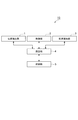
まず、図1を用いて、本実施形態に係る運転支援装置の構成について説明する。図1は、本実施形態に係る運転支援装置10の構成概略図である。運転支援装置10は、自動車等の車両(以下、自車両という。)に搭載されて、自車両の前方に存在する障害物と当該自車両との位置関係を検出し、この検出の結果に応じて、ドライバーによる自車両のより安全な運転を支援するための運転支援制御を実行する装置である。例えば、自車両と他車両とが所定時間内に接触する可能性がある位置関係である場合に、ドライバーに対して注意を促す警報や、他車両との接触を回避するような走行制御の実施等の運転支援制御が行われる。
First, the configuration of the driving support apparatus according to the present embodiment will be described with reference to FIG. FIG. 1 is a schematic configuration diagram of a
本実施形態に係る運転支援装置10は、位置検出部1(位置検出手段)、取得部2(取得手段)、脇見検知部3(脇見検知手段)、設定部4(設定手段)、及び制御部5(制御手段)を備えている。なお、設定部4及び制御部5による機能は、例えば、自車両の内部に搭載された電子制御装置であるECU(図示せず)により実現される。
The
位置検出部1は、自車両の進路方向前方に存在する障害物(以下、例として他車両とする。)を検出対象物標として検出し、この検出対象物標(即ち、他車両)と当該自車両との位置関係を演算して検出する障害物センサである。位置検出部1は、ミリ波レーダや画像センサで他車両までの距離及びその方向、相対速度及び相対加速度を演算して、他車両と自車両との位置関係を検出する。
The
取得部2は、自車両の進路上周辺の信号機に関する信号機情報(例えば、当該信号機までの距離や、現時点での信号種別等)を取得する通信機である。信号機情報は、例えば、信号機における信号種別の切り替わり、即ち、青信号、黄信号、及び赤信号の切り替わりに関する切り替わり情報(例えば、現時点での信号種別になってからの経過時間や、次の信号種別へ切り替わるまでの推定時間等)を含んでいる。取得部2が取得する信号機情報は、運転支援装置10の周囲のインフラストラクチャに関するインフラ情報や、自車両が進むべき経路を示すナビゲーションシステムに関するナビ情報等に含まれている。取得部2は、例えば、運転支援装置10の周囲にある他の自律移動装置及び車両や、交差点に設置されている信号機及び道路に設置されているカメラ、レーダ、通信装置、ビーコン等のインフラストラクチャとの間で、信号機情報を含む上記のインフラ情報やナビ情報を送受信する。
The
脇見検知部3は、自車両を運転するドライバーの状態(例えば、視線、顔向き角度、開眼度合)を監視して、当該ドライバーの脇見による信号機の見落としを検知する監視カメラである。脇見検知部3は、インストルメントパネルといった運転席周辺に設置され、運転席に着座したドライバーと相対向している。脇見検知部3は、ドライバーの顔面を撮像して解析することによって、ドライバーが脇見をしたか否かを検知する。
The look-ahead
設定部4は、運転支援制御を実行させるための実行条件(即ち、作動条件)を、取得部2が取得した信号機情報に基づいて変更して設定する演算制御ユニットである。運転支援制御は、位置検出部1による位置関係の検出結果に応じた自車両の運転を支援するために、制御部5によって行なわれる制御である。なお、設定部4は、信号機情報が含む切り替わり情報に基づいて、上記の実行条件を変更して設定することも可能である。また、設定部4は、脇見検知部3がドライバーの脇見を検知した場合に、上記の実行条件を変更して設定することも可能である。更に、設定部4は、上記の実行条件の設定と対応する閾値を変更することによって、当該実行条件を変更して設定することも可能である。例えば、所定の閾値を超過した場合に上記の制御を実行させる条件を設けた場合に、上記の制御を実行させ易くするために当該閾値をより低く設定したり、上記の制御を実行させ難くするために当該閾値をより高く設定することも可能である。
The
制御部5は、位置検出部1による位置関係の検出結果に応じた自車両の運転を支援する運転支援制御を行なう実行制御ユニットである。運転支援制御は、例えば、自車両と他車両とが所定時間内に接触する可能性がある位置関係である場合に、ドライバーに対して注意を促す警報や、他車両との接触を回避するような走行制御の実施等を行って、ドライバーやその他乗員の保護を行なう制御である。
The
引き続き、図2〜図4を用いて、走行中の自車両が減速して停止するまでの間に運転支援装置10によって行われる運転支援制御について説明する。図2〜図4のそれぞれは、走行中(図2に対応)の自車両が減速して(図3に対応)停止する(図4に対応)までの間に運転支援装置10によって行われる運転支援制御を説明するための説明図である。
Next, the driving support control performed by the driving
まず、図2に示すように、運転支援装置10を搭載して車道を走行中の自車両Cの取得部2が、車道脇に設置されているインフラ通信装置I近傍を通過する際にこのインフラ通信装置Iと路車間通信を行なって、信号機情報を受信する。これにより、自車両Cは、信号機Sまでの距離や、現時点での信号種別(ここでは青信号とする。)や、現時点での信号種別になってからの経過時間等に関する情報を取得する。なお、自車両Cの位置検出部1が障害物を検出可能な検出範囲が、システム作動範囲Aとして示されている。システム作動範囲A内に、自車両Cの進行方向前方を走行中の先行車両Pが含まれており、このように含まれた状態になると、運転支援装置10における運転支援制御システムが作動を開始する。
First, as shown in FIG. 2, when the
次に、図3に示すように、システム作動範囲A内に先行車両Pを検出した自車両Cが地点C1、C2、C3の順に移動中であるとする。より詳しくは、システム作動範囲A2は自車両Cが地点C2の位置を移動中の場合の範囲であり、システム作動範囲A3は自車両Cが地点C3の位置を移動中の場合の範囲である。このような自車両Cの移動中に、自車両Cの脇見検知部3が、ドライバーが脇見中であることを検知したとする。更に、この脇見中に、取得部2が、現時点での信号種別が青信号から黄信号に切り替わったことを示す切り替わり情報を取得して、先行車両Pが減速を開始したとする。ここで、自車両Cの設定部4が、取得部2が取得した切り替わり情報(即ち、信号機Sまでの距離や、現時点での信号種別が黄信号であること等)を含む信号機情報に基づいて、運転支援制御を実行させるための実行条件を緩めて運転支援制御を実行させ易くなるように、上記したECUにおいて変更して設定する。
Next, as shown in FIG. 3, it is assumed that the host vehicle C that has detected the preceding vehicle P within the system operation range A is moving in the order of points C1, C2, and C3. More specifically, the system operation range A2 is a range when the host vehicle C is moving at the position of the point C2, and the system operation range A3 is a range when the host vehicle C is moving at the position of the point C3. Assume that the side-by-
次に、図4に示すように、実行条件が緩められて運転支援制御を実行させ易くなった自車両Cにおける制御部5が、実行させ易くなった運転支援制御を実行させる。具体的には、制御部5が、ドライバーに対して先行車両Pと接触しないよう注意を促す警報や、先行車両Pとの接触を回避するような走行制御の実施等を行って、接触を防止させるようにする。この結果、ドライバーは、この警報に基づいて脇見をやめて自車両Cを注意深く運転するようになる。このため、現時点での信号種別が黄信号から赤信号に切り替わり、先行車両Pが停止しても、自車両Cと先行車両Pとの接触を防止することができる。
Next, as illustrated in FIG. 4, the
引き続き、図5を用いて、運転支援装置10で実行される運転支援制御の処理手順について説明する。図5は、運転支援装置10で実行される運転支援制御の処理手順を説明するためのフローチャートである。図5のフローチャートに示される処理は、主として上記したECUによって行われるものであり、運転支援装置10の電源がオンされて処理が開始してからオフされるまでの間、所定の時間間隔で繰り返し実行される。
Subsequently, a processing procedure of driving support control executed by the driving
まず、自車両Cの位置検出部1におけるシステム作動範囲A内に、自車両Cの進行方向前方を走行中の先行車両Pが含まれるという位置関係が検出されると、運転支援装置10における運転支援制御システムが作動を開始する。また、取得部2が、上記のインフラ情報やナビ情報等を例えば周囲のインフラストラクチャから取得することにより、自車両Cが交差点へ接近していることを検出する(ステップS01)。
First, when a positional relationship is detected that the preceding vehicle P traveling in the forward direction of the own vehicle C is included in the system operation range A in the
次に、取得部2が、自車両Cの進路上周辺の交差点の信号機に関する信号機情報を例えば当該信号機から受信する路車間通信を行うことにより、当該信号機までの距離や、現時点での信号種別や、現時点での信号種別になってからの経過時間等を取得する(ステップS02)。
Next, the
次に、設定部4が、ステップS02で取得された信号機情報に基づいて、運転支援制御を実行させるための実行条件を演算する。実行条件の演算にあたっては、設定部4が、この実行条件の設定と対応する作動閾値を計算して一時的に記憶する(ステップS03)。この作動閾値は、運転支援制御を実行させるか否かを決定するために用いられる基準となる閾値であり、上記のドライバー状態と、自車両Cの周辺の道路形状とに基づく数値である。例えば、この作動閾値を超過した場合に上記の制御を実行させる条件を設定部4において設けた場合に、上記の制御を実行させ易くするために当該閾値をより低く設定したり、上記の制御を実行させ難くするために当該閾値をより高く設定することが可能である。
Next, the
次に、脇見検知部3が、自車両Cを運転するドライバーの脇見を検知する検知処理を開始する(ステップS04)。
Next, the side-by-
次に、脇見検知部3が、ドライバーは脇見中であるか否かを判定する(ステップS05)。ドライバーは脇見中でない場合、ステップS02で取得された信号機情報が示す現時点での信号種別に基づいて、ステップS03で一時的に記憶された作動閾値に対して変更が加えられて設定される(ステップS11)。より詳しくは、予め定められた規定時間後に赤信号になると判断された場合、上記の実行条件を大幅に緩めて運転支援制御を非常に容易に実行させ易くなるように、一時的に記憶された作動閾値に対して大幅な変更(即ち、所定値以上の変更)を加えて設定する。
Next, the look-
一方、予め定められた規定時間後に黄信号又は青信号になると判断された場合、上記の実行条件を小幅に緩めて運転支援制御をやや容易に実行させ易くなるように(即ち、脇見運転に関してのみ警告できるように)、一時的に記憶された作動閾値に対して小幅な変更(即ち、所定値未満の変更)を加えて設定する。これにより、運転支援制御の無駄な作動が抑制される。そして、この作動閾値を超過した場合に、制御部5が、運転支援制御を実行させて、一連の処理が終了する。一方、ドライバーは脇見中である場合、後述のステップS06に移行する。
On the other hand, if it is determined that a yellow signal or a green signal will be generated after a predetermined time, a driving condition is easily relaxed by loosening the above execution conditions (that is, a warning only for the side-view driving). As a result, a small change (that is, a change less than a predetermined value) is set to the temporarily stored operation threshold value. Thereby, useless operation | movement of driving assistance control is suppressed. And when this operation threshold is exceeded, the
ステップS06では、設定部4が、ステップS02で取得された信号機情報が示す現時点での信号種別が、黄信号又は赤信号であるか否かを判定する。現時点での信号種別が黄信号又は赤信号でない場合、即ち、青信号である場合、上記の実行条件を小幅に緩めて運転支援制御をやや容易に実行させ易くなるように(即ち、脇見運転に関してのみ警告できるように)、ステップS03で一時的に記憶された作動閾値に対して小幅な変更(即ち、所定値未満の変更)が加えられて、変更後のこの作動閾値が設定される(ステップS12)。そして、この作動閾値を超過した場合に、制御部5が、やや実行させ易くなった運転支援制御を実行させて、一連の処理が終了する。一方、現時点での信号種別が黄信号又は赤信号である場合、後述のステップS07に移行する。
In step S06, the
ステップS07では、上記の実行条件を大幅に緩めて運転支援制御を容易に実行させ易くなるように、ステップS03で一時的に記憶された作動閾値に対して大幅な変更(即ち、所定値以上の変更)が加えられて、変更後のこの作動閾値が設定される。そして、この作動閾値を超過した場合に、制御部5が、大幅に実行させ易くなった運転支援制御を実行させて、一連の処理が終了する。
In step S07, the operating threshold value temporarily stored in step S03 is significantly changed (ie, greater than or equal to a predetermined value) so that the execution conditions are greatly relaxed and the driving support control is easily performed. Change) is applied to set the operation threshold after the change. And when this operation threshold is exceeded, the
引き続き、本実施形態の作用効果について説明する。本実施形態によれば、自車両Cの運転を支援する運転支援制御を実行させるための実行条件を、取得部2が取得した信号機情報に基づいて、設定部4が変更して設定する。このように、信号機情報に基づいて上記の実行条件が設定されるため、信号機Sが設置されている交差点付近において信号機Sの切り替わりの影響によって先行車両Pの速度が変わっていても脇見や信号機の見落とし等によりドライバーが気づかなくても、運転支援制御を適切なタイミング(即ち、ドライバーが煩わしいと感じない早目のタイミング)で実行して対応することが可能になる。この結果、車両のより安全な運転を支援することが可能になる。
Continuously, the effect of this embodiment is demonstrated. According to the present embodiment, the
また、信号機情報が含む切り替わり情報に基づいて、設定部4が上記の実行条件を変更して設定するため、信号機Sにおける黄信号及び赤信号への切り替わりに対して、必要な運転支援制御を適切に実行して対応することが可能になる。この結果、車両のより安全な運転を支援することが可能になる。
In addition, since the
また、ドライバーの脇見が検知された場合に、設定部4が上記の実行条件を変更して設定するため、ドライバーの脇見のタイミングに対して、必要な運転支援制御を適切に実行して対応することが可能になる。この結果、車両のより安全な運転を支援することが可能になる。
In addition, when the driver's looking aside is detected, the
また、取得部2が取得した信号機情報に基づいて、実行条件の設定と対応する上記の作動閾値が変更されるため、作動閾値を僅かに変更することによって、必要な運転支援制御をより細かく適切に実行して対応することが可能になる。この結果、車両のより安全な運転を支援することが可能になる。
Further, since the operation threshold value corresponding to the setting of the execution condition is changed based on the traffic signal information acquired by the
以上、本発明の好適な実施形態について説明したが、本発明は上記実施形態に限定されるものではない。例えば、上記実施形態では、設定部4及び制御部5による機能はECUにより実現される構成としたが、位置検出部1、取得部2、脇見検知部3、設定部4、及び制御部5による機能(又はこれらの機能の一部)がECUにより実現される構成としてもよい。
The preferred embodiment of the present invention has been described above, but the present invention is not limited to the above embodiment. For example, in the above-described embodiment, the functions of the
本発明によれば、車両のより安全な運転を支援することが可能な運転支援装置を提供することが可能である。 ADVANTAGE OF THE INVENTION According to this invention, it is possible to provide the driving assistance device which can support safer driving | operation of a vehicle.
Claims (3)
前記自車両の進路上の信号機に関する信号機情報を取得する取得手段と、
前記取得手段が取得した前記信号機情報に基づいて、前記運転支援制御を実行させるための実行条件を設定する設定手段と、
を備え、
前記信号機情報は、前記信号機の現時点での信号種別と、次の信号種別へ切り替わるまでの推定時間と、に関する切り替わり情報を含み、
前記設定手段は、前記信号機情報が含む前記切り替わり情報に基づいて、前記実行条件の設定と対応する閾値を変更することによって、前記実行条件を変更して設定する、
ことを特徴とする運転支援装置。 Driving support that includes position detection means for detecting a positional relationship between an obstacle present ahead of the host vehicle and the host vehicle, and that performs driving support control that supports driving of the host vehicle according to the detection result. A device,
Obtaining means for obtaining traffic signal information relating to traffic signals on the course of the host vehicle;
Setting means for setting an execution condition for causing the driving support control to be executed based on the traffic signal information acquired by the acquisition means;
Equipped with a,
The traffic signal information includes switching information regarding the current signal type of the traffic signal and the estimated time until switching to the next signal type,
The setting means changes and sets the execution condition by changing a threshold corresponding to the setting of the execution condition based on the switching information included in the traffic light information.
A driving support device characterized by that.
前記設定手段は、前記脇見検知手段が前記運転者の脇見を検知した場合に、前記実行条件を変更して設定する、
ことを特徴とする請求項1に記載の運転支援装置。 Further comprising an armpit detecting means for detecting the driver's armpit driving the vehicle,
The setting means changes and sets the execution condition when the looking-aside detecting means detects the driver's looking aside.
The driving support device according to claim 1 , wherein
前記自車両の進路上の信号機に関する信号機情報を取得する取得ステップと、An acquisition step of acquiring traffic signal information related to traffic signals on the route of the host vehicle;
前記取得ステップで取得された前記信号機情報に基づいて、前記運転支援制御を実行させるための実行条件を設定する設定ステップと、Based on the traffic light information acquired in the acquisition step, a setting step for setting an execution condition for executing the driving support control;
を有し、Have
前記信号機情報は、前記信号機の現時点での信号種別と、次の信号種別へ切り替わるまでの推定時間と、に関する切り替わり情報を含み、The traffic signal information includes switching information regarding the current signal type of the traffic signal and the estimated time until switching to the next signal type,
前記設定ステップでは、前記信号機情報が含む前記切り替わり情報に基づいて、前記実行条件の設定と対応する閾値を変更することによって、前記実行条件を変更して設定する、In the setting step, the execution condition is changed and set by changing a threshold corresponding to the setting of the execution condition based on the switching information included in the traffic light information.
ことを特徴とする運転支援方法。A driving support method characterized by the above.
Applications Claiming Priority (1)
| Application Number | Priority Date | Filing Date | Title |
|---|---|---|---|
| PCT/JP2008/073571 WO2010073333A1 (en) | 2008-12-25 | 2008-12-25 | Drive assistance apparatus |
Publications (2)
| Publication Number | Publication Date |
|---|---|
| JPWO2010073333A1 JPWO2010073333A1 (en) | 2012-05-31 |
| JP5267570B2 true JP5267570B2 (en) | 2013-08-21 |
Family
ID=42287002
Family Applications (1)
| Application Number | Title | Priority Date | Filing Date |
|---|---|---|---|
| JP2010543672A Active JP5267570B2 (en) | 2008-12-25 | 2008-12-25 | Driving assistance device |
Country Status (5)
| Country | Link |
|---|---|
| US (1) | US8666644B2 (en) |
| EP (1) | EP2381431B1 (en) |
| JP (1) | JP5267570B2 (en) |
| CN (1) | CN102265319B (en) |
| WO (1) | WO2010073333A1 (en) |
Families Citing this family (20)
| Publication number | Priority date | Publication date | Assignee | Title |
|---|---|---|---|---|
| DE102011117850B4 (en) * | 2011-11-08 | 2020-12-03 | Audi Ag | Method for operating a vehicle system of a motor vehicle and motor vehicle |
| US9429943B2 (en) * | 2012-03-05 | 2016-08-30 | Florida A&M University | Artificial intelligence valet systems and methods |
| CN103810877A (en) * | 2012-11-09 | 2014-05-21 | 无锡美新物联网科技有限公司 | Automobile information interaction safety system |
| DE102013222645A1 (en) * | 2013-11-07 | 2015-05-07 | Robert Bosch Gmbh | A detection system in a vehicle for detecting the voice activity of a vehicle occupant |
| JP6442904B2 (en) * | 2014-08-01 | 2018-12-26 | 株式会社デンソー | Driving assistance device |
| CN107111955B (en) * | 2015-01-09 | 2020-10-30 | 三菱电机株式会社 | Operation control device |
| CN104952249A (en) | 2015-06-10 | 2015-09-30 | 浙江吉利汽车研究院有限公司 | Driving behavior correcting method and driving behavior correcting device based on internet of vehicles |
| US9637120B2 (en) * | 2015-06-24 | 2017-05-02 | Delphi Technologies, Inc. | Cognitive driver assist with variable assistance for automated vehicles |
| JP6358269B2 (en) * | 2016-01-14 | 2018-07-18 | マツダ株式会社 | Driving assistance device |
| EP3481661A4 (en) | 2016-07-05 | 2020-03-11 | Nauto, Inc. | System and method for automatic driver identification |
| US10209081B2 (en) | 2016-08-09 | 2019-02-19 | Nauto, Inc. | System and method for precision localization and mapping |
| US10733460B2 (en) | 2016-09-14 | 2020-08-04 | Nauto, Inc. | Systems and methods for safe route determination |
| EP3513265A4 (en) | 2016-09-14 | 2020-04-22 | Nauto Global Limited | Systems and methods for near-crash determination |
| WO2018085804A1 (en) | 2016-11-07 | 2018-05-11 | Nauto Global Limited | System and method for driver distraction determination |
| US9922559B1 (en) | 2016-11-16 | 2018-03-20 | Denso International America, Inc. | Systems and methods for green light nudge monitoring and alert |
| JP2018151907A (en) * | 2017-03-14 | 2018-09-27 | オムロン株式会社 | Device for determining degree of concentration, method for determining degree of concentration, and program for determining degree of concentration |
| US10430695B2 (en) | 2017-06-16 | 2019-10-01 | Nauto, Inc. | System and method for contextualized vehicle operation determination |
| WO2018229549A2 (en) | 2017-06-16 | 2018-12-20 | Nauto Global Limited | System and method for digital environment reconstruction |
| WO2018229550A1 (en) | 2017-06-16 | 2018-12-20 | Nauto Global Limited | System and method for adverse vehicle event determination |
| EP3759700B1 (en) | 2018-02-27 | 2023-03-15 | Nauto, Inc. | Method for determining driving policy |
Citations (5)
| Publication number | Priority date | Publication date | Assignee | Title |
|---|---|---|---|---|
| JPH03271999A (en) * | 1990-03-22 | 1991-12-03 | Koyo Seiko Co Ltd | Safe driving system for car |
| JP2004110416A (en) * | 2002-09-18 | 2004-04-08 | Mitsubishi Motors Corp | Running supporting device |
| JP2004234684A (en) * | 2004-03-12 | 2004-08-19 | Hitachi Ltd | Vehicle travel controller |
| JP2005239114A (en) * | 2004-01-28 | 2005-09-08 | Toyota Motor Corp | Traveling support device for vehicle |
| JP2008204185A (en) * | 2007-02-20 | 2008-09-04 | Toyota Motor Corp | Device for determining state of psychological driving |
Family Cites Families (17)
| Publication number | Priority date | Publication date | Assignee | Title |
|---|---|---|---|---|
| US4234051A (en) * | 1978-07-26 | 1980-11-18 | Morris Jr Solon S | Driver alertness device |
| JPH07257301A (en) | 1994-03-24 | 1995-10-09 | Mitsubishi Electric Corp | Obstruction alarm system |
| JP3183161B2 (en) * | 1996-04-12 | 2001-07-03 | 三菱自動車工業株式会社 | Arousal level estimation device |
| US6130617A (en) * | 1999-06-09 | 2000-10-10 | Hyundai Motor Company | Driver's eye detection method of drowsy driving warning system |
| JP3646605B2 (en) | 2000-02-23 | 2005-05-11 | 株式会社日立製作所 | Vehicle travel control device |
| US6496117B2 (en) * | 2001-03-30 | 2002-12-17 | Koninklijke Philips Electronics N.V. | System for monitoring a driver's attention to driving |
| JP2003141698A (en) | 2001-11-06 | 2003-05-16 | Nissan Motor Co Ltd | Obstacle presence possibility detecting device and obstacle detecting device |
| JP4841425B2 (en) * | 2003-06-06 | 2011-12-21 | ボルボ テクノロジー コーポレイション | Method and mechanism for controlling automobile subsystems based on driver behavior interpretation |
| US20050128063A1 (en) * | 2003-11-28 | 2005-06-16 | Denso Corporation | Vehicle driving assisting apparatus |
| CN1914060B (en) * | 2004-01-28 | 2013-05-29 | 丰田自动车株式会社 | Running support system for vehicle |
| DE102005003192A1 (en) * | 2005-01-24 | 2006-07-27 | Robert Bosch Gmbh | Course prediction method in driver assistance systems for motor vehicles |
| KR100689784B1 (en) * | 2005-02-03 | 2007-03-08 | 주식회사 현대오토넷 | System and method for preventing traffic signal violation |
| JP2007226666A (en) | 2006-02-24 | 2007-09-06 | Aisin Aw Co Ltd | Driving support method and driving support device |
| JP2008003707A (en) | 2006-06-20 | 2008-01-10 | Matsushita Electric Ind Co Ltd | Hazard prediction device |
| US20080243378A1 (en) | 2007-02-21 | 2008-10-02 | Tele Atlas North America, Inc. | System and method for vehicle navigation and piloting including absolute and relative coordinates |
| JP4888212B2 (en) * | 2007-04-25 | 2012-02-29 | 株式会社デンソー | Vehicle alarm device |
| US20100070128A1 (en) * | 2008-09-15 | 2010-03-18 | Microsoft Corporation | vehicle operation by leveraging traffic related data |
-
2008
- 2008-12-25 EP EP08879129.8A patent/EP2381431B1/en active Active
- 2008-12-25 WO PCT/JP2008/073571 patent/WO2010073333A1/en active Application Filing
- 2008-12-25 JP JP2010543672A patent/JP5267570B2/en active Active
- 2008-12-25 CN CN200880132528.7A patent/CN102265319B/en active Active
- 2008-12-25 US US13/129,971 patent/US8666644B2/en active Active
Patent Citations (5)
| Publication number | Priority date | Publication date | Assignee | Title |
|---|---|---|---|---|
| JPH03271999A (en) * | 1990-03-22 | 1991-12-03 | Koyo Seiko Co Ltd | Safe driving system for car |
| JP2004110416A (en) * | 2002-09-18 | 2004-04-08 | Mitsubishi Motors Corp | Running supporting device |
| JP2005239114A (en) * | 2004-01-28 | 2005-09-08 | Toyota Motor Corp | Traveling support device for vehicle |
| JP2004234684A (en) * | 2004-03-12 | 2004-08-19 | Hitachi Ltd | Vehicle travel controller |
| JP2008204185A (en) * | 2007-02-20 | 2008-09-04 | Toyota Motor Corp | Device for determining state of psychological driving |
Also Published As
| Publication number | Publication date |
|---|---|
| EP2381431A4 (en) | 2012-07-25 |
| US20110245993A1 (en) | 2011-10-06 |
| JPWO2010073333A1 (en) | 2012-05-31 |
| CN102265319B (en) | 2015-06-17 |
| US8666644B2 (en) | 2014-03-04 |
| EP2381431B1 (en) | 2013-07-03 |
| CN102265319A (en) | 2011-11-30 |
| EP2381431A1 (en) | 2011-10-26 |
| WO2010073333A1 (en) | 2010-07-01 |
Similar Documents
| Publication | Publication Date | Title |
|---|---|---|
| JP5267570B2 (en) | Driving assistance device | |
| JP6269606B2 (en) | Vehicle control device | |
| JP4628683B2 (en) | Pedestrian detection device and vehicle driving support device including the pedestrian detection device | |
| EP3219568A1 (en) | Auto driving control system | |
| JP7420187B2 (en) | Notification device | |
| JP5888407B2 (en) | Driving assistance device | |
| JP6485328B2 (en) | Vehicle driving support device | |
| US11180164B2 (en) | Vehicle control apparatus, vehicle, and control method | |
| JP6323063B2 (en) | Traveling lane identification device, lane change support device, traveling lane identification method | |
| JP2006127055A (en) | Information presentation device for vehicle | |
| JP2014041556A (en) | Driving support device | |
| JP2008168827A (en) | Lane change supporter | |
| JP2010079565A (en) | Drive assist device | |
| JP2019028841A (en) | Outboard notification device | |
| JP2019197303A (en) | Vehicle outside notification device | |
| JP2008046845A (en) | Cutting-in vehicle determination apparatus | |
| JP2017102839A (en) | Driving support device | |
| JP2007320536A (en) | Parallel travelling vehicle monitoring device | |
| JP2021046182A (en) | Self-driving car | |
| JP2017062583A (en) | Danger information notification system, server and computer program | |
| JP2017111498A (en) | Driving support device | |
| JP2016224553A (en) | Traffic information display system for vehicle | |
| JP2019199143A (en) | ECU and lane departure warning system | |
| JP6520691B2 (en) | Lane deviation warning device and lane deviation warning method | |
| KR20220069520A (en) | Vehicle driving control system and control method thereof at roundabout |
Legal Events
| Date | Code | Title | Description |
|---|---|---|---|
| A131 | Notification of reasons for refusal |
Free format text: JAPANESE INTERMEDIATE CODE: A131 Effective date: 20121218 |
|
| A521 | Request for written amendment filed |
Free format text: JAPANESE INTERMEDIATE CODE: A523 Effective date: 20130201 |
|
| TRDD | Decision of grant or rejection written | ||
| A01 | Written decision to grant a patent or to grant a registration (utility model) |
Free format text: JAPANESE INTERMEDIATE CODE: A01 Effective date: 20130409 |
|
| A61 | First payment of annual fees (during grant procedure) |
Free format text: JAPANESE INTERMEDIATE CODE: A61 Effective date: 20130422 |
|
| R151 | Written notification of patent or utility model registration |
Ref document number: 5267570 Country of ref document: JP Free format text: JAPANESE INTERMEDIATE CODE: R151 |