JP5266846B2 - POSITIONING METHOD, PROGRAM, AND POSITIONING DEVICE - Google Patents
POSITIONING METHOD, PROGRAM, AND POSITIONING DEVICE Download PDFInfo
- Publication number
- JP5266846B2 JP5266846B2 JP2008094954A JP2008094954A JP5266846B2 JP 5266846 B2 JP5266846 B2 JP 5266846B2 JP 2008094954 A JP2008094954 A JP 2008094954A JP 2008094954 A JP2008094954 A JP 2008094954A JP 5266846 B2 JP5266846 B2 JP 5266846B2
- Authority
- JP
- Japan
- Prior art keywords
- kalman filter
- model
- value
- positioning
- likelihood
- Prior art date
- Legal status (The legal status is an assumption and is not a legal conclusion. Google has not performed a legal analysis and makes no representation as to the accuracy of the status listed.)
- Expired - Fee Related
Links
Images


Classifications
-
- G—PHYSICS
- G01—MEASURING; TESTING
- G01S—RADIO DIRECTION-FINDING; RADIO NAVIGATION; DETERMINING DISTANCE OR VELOCITY BY USE OF RADIO WAVES; LOCATING OR PRESENCE-DETECTING BY USE OF THE REFLECTION OR RERADIATION OF RADIO WAVES; ANALOGOUS ARRANGEMENTS USING OTHER WAVES
- G01S19/00—Satellite radio beacon positioning systems; Determining position, velocity or attitude using signals transmitted by such systems
- G01S19/38—Determining a navigation solution using signals transmitted by a satellite radio beacon positioning system
- G01S19/39—Determining a navigation solution using signals transmitted by a satellite radio beacon positioning system the satellite radio beacon positioning system transmitting time-stamped messages, e.g. GPS [Global Positioning System], GLONASS [Global Orbiting Navigation Satellite System] or GALILEO
- G01S19/42—Determining position
Landscapes
- Engineering & Computer Science (AREA)
- Radar, Positioning & Navigation (AREA)
- Remote Sensing (AREA)
- Computer Networks & Wireless Communication (AREA)
- Physics & Mathematics (AREA)
- General Physics & Mathematics (AREA)
- Position Fixing By Use Of Radio Waves (AREA)
- Navigation (AREA)
Abstract
Description
本発明は、測位装置が、各カルマンフィルタ処理それぞれをモデルとみなし、前記カルマンフィルタ処理それぞれの処理結果を所定のモデル確率で重みづけして合成するIMM演算を行って測位する測位方法等に関する。 The present invention relates to a positioning method in which a positioning device regards each Kalman filter process as a model, performs positioning by performing an IMM operation that weights and combines the processing results of the Kalman filter processes with a predetermined model probability, and the like.
人工衛星を利用した測位システムとしては、GPS(Global Positioning System)が広く知られており、携帯型電話機やカーナビゲーション装置等に内蔵された測位装置に利用されている。GPSでは、自機の位置を示す3次元の座標値と、時計誤差との4つのパラメータの値を、複数のGPS衛星の位置や各GPS衛星から自機までの擬似距離等の情報に基づいて求める測位演算を行うことで、自機の現在位置を測位する。 As a positioning system using an artificial satellite, a GPS (Global Positioning System) is widely known, and is used in a positioning device built in a mobile phone, a car navigation device, or the like. In GPS, the values of four parameters, the three-dimensional coordinate value indicating the position of the aircraft and the clock error, are calculated based on information such as the positions of a plurality of GPS satellites and the pseudoranges from each GPS satellite to the aircraft The current position of the aircraft is measured by performing the required positioning calculation.
測位演算としては、最小二乗法を用いた測位演算や、カルマンフィルタを用いた測位演算が知られている。そして、カルマンフィルタを用いた測位演算を応用した技術として、測位装置の移動状態に対応する複数のカルマンフィルタモデルを用意して各モデルについて測位演算を行い、その測位演算の結果を合成して測位位置を決定するインタラクティブミキシングモデル(Interactive Mixing Model)演算(以下、「IMM演算」と称す。)が知られている(例えば、非特許文献1)。
IMM演算による測位では、カルマンフィルタの入力値となる外部観測量の尤もらしさ(以下、「尤度」と称す。)を、尤度関数と呼ばれる正規分布(ガウス分布)に従った関数から算出し、この算出した尤度を用いて、各カルマンフィルタモデルの確率(以下、「モデル確率」と称す。)を算出する。そして、算出したモデル確率を用いて各カルマンフィルタモデルの処理結果を合成することで、測位装置の現在位置を求める。 In the positioning by the IMM calculation, the likelihood of the external observation amount that becomes the input value of the Kalman filter (hereinafter referred to as “likelihood”) is calculated from a function according to a normal distribution (Gaussian distribution) called a likelihood function, Using the calculated likelihood, the probability of each Kalman filter model (hereinafter referred to as “model probability”) is calculated. And the present position of a positioning device is calculated | required by synthesize | combining the processing result of each Kalman filter model using the calculated model probability.
しかし、尤度関数はEXP(Exponential)関数で表されるため、EXP関数の指数部分が非常に小さな値(例えば「−20以下」)になると、尤度は限りなく「0」に近くなり、計算機で計算しようとしても演算可能な数値範囲の関係から結局「0」になってしまう。モデル確率は尤度を用いて算出するため、尤度が「0」になってしまうと、モデル確率を正しく算出することができず、その結果、測位位置を求めることができないという大きな問題があった。 However, since the likelihood function is expressed by an EXP (Exponential) function, when the exponent part of the EXP function becomes a very small value (for example, “−20 or less”), the likelihood is almost as close to “0”, Even if it tries to calculate with a computer, it will eventually become “0” due to the relationship of the range of numerical values that can be calculated. Since the model probability is calculated using the likelihood, if the likelihood becomes “0”, the model probability cannot be calculated correctly, and as a result, the positioning position cannot be obtained. It was.
本発明は、上述した課題に鑑みて為されたものである。 The present invention has been made in view of the above-described problems.
以上の課題を解決するための第1の発明は、測位装置が、各カルマンフィルタ処理それぞれをモデルとみなし、前記カルマンフィルタ処理それぞれの処理結果を所定のモデル確率で重みづけして合成するIMM演算を行って測位する測位方法であって、前記カルマンフィルタ処理それぞれの尤度指標値を算出することと、前記算出された尤度指標値の前記カルマンフィルタ処理間の相対値を算出することと、前記算出された相対値を用いて前記カルマンフィルタ処理それぞれの前記モデル確率を算出することと、前記算出されたモデル確率を用いて前記カルマンフィルタ処理それぞれの処理結果を合成することで測位位置を決定することと、を含む測位方法である。 In a first invention for solving the above-described problem, the positioning device performs an IMM operation that regards each Kalman filter process as a model, and weights and combines each Kalman filter process result with a predetermined model probability. And calculating a likelihood index value of each of the Kalman filter processes, calculating a relative value between the Kalman filter processes of the calculated likelihood index values, and calculating the calculated Calculating the model probabilities of each of the Kalman filter processes using relative values, and determining a positioning position by combining the processing results of the Kalman filter processes using the calculated model probabilities. It is a positioning method.
また、他の発明として、各カルマンフィルタ処理それぞれをモデルとみなし、前記カルマンフィルタ処理それぞれの処理結果を所定のモデル確率で重みづけして合成するIMM演算を行って測位する測位装置であって、前記カルマンフィルタ処理それぞれの尤度指標値を算出する指標値算出部と、前記算出された尤度指標値の前記カルマンフィルタ処理間の相対値を算出する相対値算出部と、前記算出された相対値を用いて前記カルマンフィルタ処理それぞれの前記モデル確率を算出するモデル確率算出部と、前記算出されたモデル確率を用いて前記カルマンフィルタ処理それぞれの処理結果を合成することで測位位置を決定する測位位置決定部と、を備えた測位装置を構成してもよい。 According to another aspect of the present invention, there is provided a positioning apparatus that performs positioning by performing an IMM operation that regards each Kalman filter process as a model and weights and combines the processing results of the Kalman filter processes with a predetermined model probability. An index value calculation unit that calculates a likelihood index value of each process, a relative value calculation unit that calculates a relative value of the calculated likelihood index value between the Kalman filter processes, and the calculated relative value A model probability calculation unit that calculates the model probability of each of the Kalman filter processes, and a positioning position determination unit that determines a positioning position by combining the processing results of the Kalman filter processes using the calculated model probabilities. You may comprise the positioning device provided.
この第1の発明等によれば、カルマンフィルタ処理それぞれの尤度指標値が算出され、この尤度指標値のカルマンフィルタ処理間の相対値が算出される。そして、算出された相対値を用いてカルマンフィルタ処理それぞれのモデル確率が算出され、このモデル確率を用いてカルマンフィルタ処理それぞれの処理結果が合成されることで測位位置が決定される。 According to the first aspect of the invention, the likelihood index value of each Kalman filter process is calculated, and the relative value of the likelihood index value between the Kalman filter processes is calculated. Then, the model probabilities of the respective Kalman filter processes are calculated using the calculated relative values, and the positioning position is determined by combining the process results of the respective Kalman filter processes using the model probabilities.
ここで、尤度指標値とは、カルマンフィルタの入力値となる外部観測量の尤度を算出するための尤度関数の指数部分のことを指す。IMM演算におけるモデル確率は、尤度指標値を用いて算出した外部観測量の尤度を基に算出することができるが、尤度指標値が非常に小さな値である場合には、計算機で計算しようとしても演算可能な数値範囲の関係で尤度が「0」になってしまい、モデル確率を正しく求めることができない。 Here, the likelihood index value refers to the exponent part of the likelihood function for calculating the likelihood of the external observation amount that is the input value of the Kalman filter. The model probability in the IMM calculation can be calculated based on the likelihood of the external observation amount calculated using the likelihood index value. If the likelihood index value is a very small value, it is calculated by a computer. Even if an attempt is made, the likelihood becomes “0” because of the range of numerical values that can be calculated, and the model probability cannot be obtained correctly.
本願発明者は、この問題を解決するため、尤度指標値をそのまま用いるのではなく、複数のカルマンフィルタ処理間の尤度指標値の相対値を用いることで、モデル確率を正しく求めることができることを発見した。これは、個々の尤度指標値が非常に小さな値であったとしても、尤度指標値の相対値は概ね「0」の近傍の値となり、指数関数に当該相対値を与えて計算すると「0」とはならない点に着目したものである。かかる原理により、モデル確率を正しく算出することが可能となり、その結果、正確な測位位置の算出を実現し得る。 In order to solve this problem, the present inventor does not use the likelihood index value as it is, but uses the relative value of the likelihood index value between a plurality of Kalman filter processes, so that the model probability can be obtained correctly. discovered. This is because even if each likelihood index value is a very small value, the relative value of the likelihood index value is a value in the vicinity of “0”. It pays attention to the point which does not become "0". With this principle, it is possible to correctly calculate the model probability, and as a result, accurate positioning position calculation can be realized.
また、第2の発明として、第1の発明の測位方法であって、前記モデル確率を算出することは、前記相対値が小さいほど値が小さくなる所定の指数関数を用いて前記モデル確率を算出することである測位方法を構成してもよい。 According to a second aspect of the present invention, in the positioning method of the first aspect, the calculation of the model probability includes calculating the model probability using a predetermined exponential function that decreases as the relative value decreases. You may comprise the positioning method which is to do.
この第2の発明によれば、カルマンフィルタ処理間の尤度指標値の相対値が小さいほど値が小さくなる指数関数(例えば、尤度指標値の相対値を変数とするEXP関数)を用いてモデル確率が算出される。 According to the second aspect of the invention, an exponential function (for example, an EXP function having the relative value of the likelihood index value as a variable) becomes smaller as the relative value of the likelihood index value between the Kalman filter processes is smaller. Probability is calculated.
また、第3の発明として、第2の発明の測位方法であって、前記モデル確率を算出することは、前記相対値を用いて算出した前記所定の指数関数の値が極限値相当値を示す条件である所定の極限値条件を満たすか否かを判定することと、前記所定の極限値条件を満たす場合に、前記指数関数の値を極限値とみなして前記モデル確率を算出することと、を含む測位方法を構成してもよい。 Further, as a third invention, in the positioning method of the second invention, the calculation of the model probability is that the value of the predetermined exponential function calculated using the relative value indicates a limit value equivalent value. Determining whether or not a predetermined limit value condition that is a condition is satisfied, and calculating the model probability by regarding the value of the exponential function as a limit value when the predetermined limit value condition is satisfied, You may comprise the positioning method containing.
この第3の発明によれば、カルマンフィルタ処理間の尤度指標値の相対値を用いて算出した指数関数の値が極限値条件を満たす場合は、当該指数関数の値を極限値とみなしてモデル確率が算出される。これにより、指数関数の値が0に収束したり、+∞に発散する場合であっても、計算機によってモデル確率を求めることが可能となる。 According to the third invention, when the value of the exponent function calculated using the relative value of the likelihood index value between the Kalman filter processes satisfies the limit value condition, the value of the exponent function is regarded as the limit value and the model Probability is calculated. Thereby, even when the value of the exponential function converges to 0 or diverges to + ∞, the model probability can be obtained by the computer.
また、第4の発明として、第3の発明の測位方法であって、前記所定の極限値条件には、最大値相当値を示す条件と最小値相当値を示す条件とが含まれ、前記モデル確率を算出することは、前記所定の極限値条件を満たす場合に、前記最大値相当値を示す条件を満たすか、前記最小値相当値を示す条件を満たすかに応じて、前記モデル確率を1又は0とすることを含む測位方法を構成してもよい。 As a fourth invention, in the positioning method of the third invention, the predetermined limit value condition includes a condition indicating a maximum value equivalent value and a condition indicating a minimum value equivalent value, and the model The calculation of the probability means that, when the predetermined limit value condition is satisfied, the model probability is set to 1 depending on whether the condition indicating the maximum value equivalent value or the condition indicating the minimum value equivalent value is satisfied. Alternatively, a positioning method including setting to 0 may be configured.
この第4の発明によれば、カルマンフィルタ処理間の尤度指標値の相対値を用いて算出した指数関数の値が最大値相当値を示す条件を満たすか、最小値相当値を満たすかに応じて、モデル確率が1又は0とされる。 According to the fourth aspect of the invention, depending on whether the value of the exponential function calculated using the relative value of the likelihood index value between the Kalman filter processes satisfies the condition indicating the maximum value equivalent value or the minimum value equivalent value Thus, the model probability is set to 1 or 0.
また、第5の発明として、第1〜第4の何れかの発明の測位方法であって、前記複数のカルマンフィルタ処理には、前記測位装置の移動状態として、停止状態にあることを前提としたカルマンフィルタ処理と、等速移動状態にあることを前提としたカルマンフィルタ処理と、定加速度状態にあることを前提としたカルマンフィルタ処理との3種類のカルマンフィルタ処理が少なくとも含まれる測位方法を構成してもよい。 Further, as a fifth invention, the positioning method according to any one of the first to fourth inventions, on the premise that the plurality of Kalman filter processes are in a stopped state as a moving state of the positioning device. A positioning method including at least three types of Kalman filter processing, that is, Kalman filter processing based on the assumption that the Kalman filter processing is in a constant-velocity movement state, and Kalman filter processing that is based on a constant acceleration state may be configured. .
この第5の発明によれば、測位装置の移動状態として、停止状態と、等速移動状態と、定加速度状態とに対応する3種類のカルマンフィルタ処理が行われ、これらのカルマンフィルタ処理の処理結果が合成される。 According to the fifth aspect of the present invention, three types of Kalman filter processing corresponding to the stop state, the constant speed movement state, and the constant acceleration state are performed as the movement state of the positioning device, and the processing results of these Kalman filter processes are as follows. Synthesized.
また、第6の発明として、第1〜第5の何れかの発明の測位方法を前記測位装置に内蔵されたコンピュータに実行させるためのプログラムを構成してもよい。 Further, as a sixth invention, a program for causing a computer incorporated in the positioning device to execute the positioning method of any one of the first to fifth inventions may be configured.
1.原理
図1は、本実施形態におけるインタラクティブミキシングモデル(Interactive Mixing Model:以下、「IMM」と称す。)の概要を説明するための図である。ここでは、説明を分かりやすくするため、複数の処理回路ブロックにおける演算によってIMM演算が実現されるものとして説明するが、単独のプロセッサによってIMM演算を実現することも可能であり、図2及び図3の処理フローの説明においては単独のプロセッサにより実行するものとして説明する。
1. Principle FIG. 1 is a diagram for explaining an outline of an interactive mixing model (hereinafter referred to as “IMM”) in the present embodiment. Here, in order to make the explanation easy to understand, the description will be made assuming that the IMM operation is realized by operations in a plurality of processing circuit blocks. However, the IMM operation can also be realized by a single processor. In the description of the processing flow, it is assumed that the processing is executed by a single processor.
IMMは、複数のカルマンフィルタモデル(Kalman Filter Model:以下、「KFモデル」と称す。)それぞれの処理結果をモデル確率「μ」と呼ばれる重みで合成することで、最終的な出力値を決定するモデルである。図1では、第1KFモデル〜第nKFモデルの「n個」のKFモデルを含むIMMを図示している。 The IMM is a model that determines the final output value by combining the processing results of each of a plurality of Kalman Filter Models (hereinafter referred to as “KF model”) with a weight called a model probability “μ”. It is. FIG. 1 illustrates an IMM including “n” KF models from the first KF model to the nth KF model.
また、説明の簡明化のため、各KFモデルに対して、単一の外部観測量(本実施形態では「メジャメント実測値」が相当する。)「Z」が与えられるものとして説明するが、複数のメジャメント実測値が与えられる場合についても同様である。メジャメント実測値は、IMM演算を適用するシステムに応じて適宜設定することができる。 Further, for the sake of simplification of explanation, it is assumed that a single external observation amount (corresponding to “measurement actual measurement value” in this embodiment) “Z” is given to each KF model. The same applies to the case where the actual measurement value is given. The actual measurement value can be appropriately set according to the system to which the IMM calculation is applied.
IMM演算では、ミキサが、各KFモデル間の遷移確率を示すモデル間遷移確率「p」と、1つ前のステップにおいてモデル確率更新部により更新されたモデル確率「μ:μ1,μ2・・・,μn」と、各KFモデルそれぞれにおいて算出された状態ベクトルの計算値「X:X1,X2,・・・,Xn」及び誤差共分散の計算値「P:P1,P2,・・・,Pn」とを用いて、各KFモデルそれぞれの状態ベクトル及び誤差共分散の今回の計算における初期値「X0:X01,X02,・・・,X0n」及び「P0:P01,P02,・・・,P0n」を算出し、計算結果を、対応するKFモデルにそれぞれ出力する。 In the IMM calculation, the mixer performs an inter-model transition probability “p” indicating the transition probability between the KF models, and the model probability “μ: μ 1 , μ 2 , updated by the model probability update unit in the previous step. .., Μ n ”, calculated values of state vectors calculated for each KF model“ X: X 1 , X 2 ,..., X n ”and calculated values of error covariance“ P: P 1 , P 2 ,..., P n ”and the initial values“ X 0 : X 01 , X 02 ,..., X 0n ”in the current calculation of the state vector and error covariance of each KF model. And “P 0 : P 01 , P 02 ,..., P 0n ” are calculated and the calculation results are output to the corresponding KF models.
また、ミキサは、モデル間遷移確率「p」と、1つ前のステップにおいてモデル確率更新部により更新されたモデル確率「μ」とを用いて、規格化定数「CN:C1,C2,・・・,Cn」と呼ばれる定数を算出して、モデル確率更新部に出力する。 Also, the mixer uses the inter-model transition probability “p” and the model probability “μ” updated by the model probability update unit in the previous step, and uses the normalization constants “CN: C 1 , C 2 , .., C n ”are calculated and output to the model probability updating unit.
各KFモデルは、ミキサから入力した初期値「X0」及び「P0」と、メジャメント実測値「Z:Z1,Z2,・・・,Zn」とを用いて、公知のカルマンフィルタと同様、予測演算と補正演算とを行うことで、状態ベクトル及び誤差共分散の今回の計算値を算出して、モデル確率更新部に出力する。また、各KFモデルは、尤度指標値「Vx:Vx1,Vx2,・・・,Vxn」と重み係数「β:β1,β2,・・・,βn」と呼ばれる値を算出して、モデル確率更新部に出力する。 Each KF model uses a known Kalman filter by using initial values “X 0 ” and “P 0 ” input from the mixer and measurement actual values “Z: Z 1 , Z 2 ,..., Z n ”. Similarly, the current calculation value of the state vector and the error covariance is calculated by performing the prediction calculation and the correction calculation, and is output to the model probability update unit. In addition, each KF model, the likelihood index value "Vx: Vx 1, Vx 2, ···, Vx n " and the weighting coefficient "β: β 1, β 2, ···, β n " a value called Calculate and output to the model probability update unit.
尤度指標値「Vx」は、メジャメント実測値「Z」の尤もらしさ(以下、「尤度」と称す。)を算出するための関数である尤度関数の指数部分として表される値である。また、重み係数「β」は、尤度関数の係数部分として表される値である。 The likelihood index value “Vx” is a value expressed as an exponent part of a likelihood function which is a function for calculating the likelihood of the measurement actual value “Z” (hereinafter referred to as “likelihood”). . The weight coefficient “β” is a value expressed as a coefficient part of the likelihood function.
モデル確率更新部は、ミキサから入力した規格化定数「CN」と、KFモデルから入力した尤度指標値「Vx」及び重み係数「β」とを用いて、モデル確率「μ」を新たに算出・更新する。そして、KFモデルから入力した状態ベクトル及び誤差共分散それぞれを、算出したモデル確率「μ」で重み付けして合成することで、状態ベクトルの出力値「X」及び誤差共分散の出力値「P」を算出する。 The model probability update unit newly calculates the model probability “μ” using the normalization constant “CN” input from the mixer, the likelihood index value “Vx” and the weight coefficient “β” input from the KF model. ·Update. Then, each of the state vector and the error covariance input from the KF model is synthesized by weighting with the calculated model probability “μ”, whereby the state vector output value “X” and the error covariance output value “P”. Is calculated.
次に、実際の数式を参照しながら、単一のプロセッサでIMM演算を実現する場合の処理の流れについて説明する。以下の数式において、各変数の添え字の「j」は、j番目のKFモデルに対応する変数であることを示しているものとする。 Next, a flow of processing when an IMM operation is realized by a single processor will be described with reference to actual mathematical expressions. In the following equations, the subscript “j” of each variable indicates a variable corresponding to the jth KF model.
図2は、プロセッサの一種であるCPU(Central Processing Unit)が実行するIMM演算処理の流れを示すフローチャートである。
先ず、CPUは、モデル間遷移確率「p」を取得する(ステップS1)。モデル間遷移確率「p」は、次式(1)に示すようなn×nの行列で与えられる。

First, the CPU acquires the inter-model transition probability “p” (step S1). The inter-model transition probability “p” is given by an n × n matrix as shown in the following equation (1).
行列の成分「pnm」は、n番目のKFモデルからm番目のKFモデルへの遷移の確率を示している。例えば、行列の成分「p11」は、第1KFモデルから第1KFモデル(自身)への遷移の確率を示しており、行列の成分「p12」は、第1KFモデルから第2KFモデルへの遷移の確率を示している。また、各行「i」の成分を合算した値は「1」である。すなわち、「pi1+pi2+・・・+pin=1」である。 The matrix component “p nm ” indicates the probability of transition from the nth KF model to the mth KF model. For example, the matrix component “p 11 ” represents the probability of transition from the first KF model to the first KF model (self), and the matrix component “p 12 ” represents the transition from the first KF model to the second KF model. The probability of Also, the sum of the components in each row “i” is “1”. That is, “p i1 + p i2 +... + P in = 1”.
次いで、CPUは、次式(2)に従って規格化定数「CN」を算出する(ステップS3)。
次いで、CPUは、次式(3)に従って、合成確率「γ」を算出する(ステップS5)。
その後、CPUは、次式(4)及び(5)に従って、KF処理における状態ベクトルの初期値「X0」及び誤差共分散の初期値「P0」を算出する(ステップS7)。
![]()
![]()
![]()
![]()
次いで、CPUは、各KFモデルそれぞれについて、ループAの処理を実行する(ステップS9〜S23)。ループAでは、CPUは、次式(6)及び(7)に従って予測演算を行って、状態ベクトル及び誤差共分散を予測する(ステップS11)。
![]()
![]()
![]()
![]()
次いで、CPUは、外部(例えば外部観測量を検出するセンサ)からメジャメント実測値「Z」を取得する(ステップS13)。また、CPUは、ステップS11で予測した状態ベクトルの予測値「X−」を用いて、外部観測量の予測値(以下、「メジャメント予測値」と称す。)を算出する(ステップS15)。メジャメント予測値は、所定の観測行列「H」と状態ベクトルの予測値「X−」との積「HX−」で表される。 Next, the CPU acquires a measured measurement value “Z” from the outside (for example, a sensor that detects an external observation amount) (step S13). Further, the CPU calculates a predicted value of the external observation amount (hereinafter referred to as “measurement predicted value”) using the predicted value “X − ” of the state vector predicted in step S11 (step S15). The measurement prediction value is represented by a product “HX − ” of a predetermined observation matrix “H” and a state vector prediction value “X − ”.
その後、CPUは、補正演算を行って、ステップS11で予測した状態ベクトル及び誤差共分散を補正する(ステップS17)。具体的には、先ず次式(8)に従って、カルマンゲイン「K」と呼ばれるゲインを算出する。
![]()
![]()
そして、CPUは、メジャメント実測値「Z」とメジャメント予測値「HX−」とを用いて、次式(9)及び(10)に従って、状態ベクトル及び誤差共分散を補正する。
![]()
![]()
![]()
![]()
次いで、CPUは、次式(11)に従って、尤度指標値「Vx」を算出する。
![]()
![]()
また、CPUは、次式(12)に従って、重み係数「β」を算出する。
全てのKFモデルについてステップS11〜S21の処理を行った後、CPUは、ループAを終了する。その後、CPUは、各KFモデル同士の相対的な組合せそれぞれにおける尤度指標値「Vx」の相対値を算出する(ステップS25)。例えば、第1KFモデル〜第3KFモデルの3つのKFモデルが存在する場合は、「Vx1−Vx2」、「Vx2−Vx1」、「Vx1−Vx3」、「Vx3−Vx1」、「Vx2−Vx3」及び「Vx3−Vx2」の6つの相対的な組合せに対して、それぞれの値を、尤度指標値の相対値として算出する。 After performing the processing of steps S11 to S21 for all the KF models, the CPU ends the loop A. Thereafter, the CPU calculates a relative value of the likelihood index value “Vx” in each of the relative combinations of the KF models (step S25). For example, when there are three KF models of the first KF model to the third KF model, “Vx 1 −Vx 2 ”, “Vx 2 −Vx 1 ”, “Vx 1 −Vx 3 ”, “Vx 3 −Vx 1”. ”,“ Vx 2 −Vx 3 ”, and“ Vx 3 −Vx 2 ”, the respective values are calculated as relative values of likelihood index values.
その後、CPUは、ステップS25で算出した相対値それぞれが、所定の最大値相当値(例えば「+20」)以上となったか、また、所定の最小値相当値(例えば「−20」)以下となったか否かを判定する(ステップS27)。 Thereafter, the CPU determines whether each of the relative values calculated in step S25 is equal to or greater than a predetermined maximum value equivalent value (eg, “+20”) or less than a predetermined minimum value equivalent value (eg, “−20”). It is determined whether or not (step S27).
そして、CPUは、次式(13−2)で与えられるモデル確率「μ」の式の分母において、相対値が最大値相当値以上となったと判定した項は「+∞」、相対値が最小値相当値以下となったと判定した項は「0」として、各KFモデルそれぞれについてモデル確率「μ」を算出する(ステップS29)。
より具体的には、相対値が最大値相当値以上となった項が1つでも存在する場合は、モデル確率「μ」を「0」とし、全ての項の相対値が最小値相当値以下となった場合は、モデル確率「μ」を「1」とする。 More specifically, when there is even one term whose relative value is equal to or greater than the maximum value, the model probability “μ” is set to “0”, and the relative values of all terms are equal to or smaller than the minimum value. In this case, the model probability “μ” is set to “1”.
尚、式(13−1)における「λ」は、次式(14)で与えられる尤度であり、「C」は、次式(15)で与えられる規格化定数である。
![]()
![]()
![]()
![]()
次いで、CPUは、ステップS29で算出したモデル確率「μ」を用いて、次式(16)及び(17)に従って、状態ベクトル及び誤差共分散の出力値「X」及び「P」を決定する(ステップS31)。そして、CPUは、IMM演算処理を終了する。
![]()
![]()
![]()
![]()
2.実験結果
次に、KFモデルが、第1KFモデル及び第2KFモデルの2つである場合に、各KFモデルそれぞれについてモデル確率「μ」を算出した場合の実験結果について説明する。ここでは、第1KFモデルの尤度指標値「Vx1」を「−20」、第1KFモデルの尤度指標値「Vx2」を「−21」として実験を行った。KFモデルが2つである場合は、次式(18)及び(19)に従ってモデル確率「μ1」及び「μ2」を算出する。
図4は、従来の手法に則って、式(18−1)及び(19―1)によりモデル確率「μ1」及び「μ2」を算出した場合の各種パラメータの値を示した図である。この結果を見ると、「λ1」及び「λ2」が共に「0」であるために、「λ1C1」及び「λ2C2」が「0」となり、「C=λ1C1+λ2C2」も「0」となっている。これにより、式(18−1)及び(19−1)の分母がそれぞれ「0」となるため、モデル確率「μ1」及び「μ2」は不定となっている。 FIG. 4 is a diagram showing values of various parameters when the model probabilities “μ 1 ” and “μ 2 ” are calculated by the equations (18-1) and (19-1) according to the conventional method. . From this result, since both “λ 1 ” and “λ 2 ” are “0”, “λ 1 C 1 ” and “λ 2 C 2 ” are “0”, and “C = λ 1 C “1 + λ 2 C 2 ” is also “0”. Thereby, since the denominators of the equations (18-1) and (19-1) are “0”, the model probabilities “μ 1 ” and “μ 2 ” are indefinite.
この様子を定性的に示したグラフが、図6である。同図において、横軸は「Vx1」、縦軸は「y=exp(Vx1)」をそれぞれ示している。上記の実験では、「Vx1」の値が「−20」であるが、このグラフを見ると、「y」の値はほぼ「0」となることがわかる。また、「Vx2」の値は「−21」であるが、この場合も同様である。 FIG. 6 is a graph qualitatively showing this state. In the figure, the horizontal axis indicates “Vx 1 ” and the vertical axis indicates “y = exp (Vx 1 )”. In the above experiment, the value of “Vx 1 ” is “−20”, but it can be seen from the graph that the value of “y” is almost “0”. Further, the value of “Vx 2 ” is “−21”, but the same applies to this case.
すなわち、従来の手法では、各KFモデルそれぞれについて算出された尤度指標値「Vx」が非常に小さな負の領域(図6のハッチング領域)に集中すると、EXP関数の値が演算可能な数値範囲の関係で「0」となり、式(14)により算出される尤度「λ」は「0」になってしまうという問題がある。尤度が「0」になると、式(13−1)によってモデル確率「μ」を算出することができない。 That is, in the conventional method, when the likelihood index value “Vx” calculated for each KF model is concentrated in a very small negative area (hatched area in FIG. 6), the numerical value range in which the value of the EXP function can be calculated Therefore, there is a problem that the likelihood “λ” calculated by the equation (14) becomes “0”. When the likelihood becomes “0”, the model probability “μ” cannot be calculated by the equation (13-1).
図5は、本実施形態の手法に則って、式(18−2)及び(19−2)によりモデル確率「μ1」及び「μ2」を算出した場合の各種パラメータの値を示した図である。この結果を見ると、尤度指標値「Vx1」及び「Vx2」ではなく、その相対値「Vx2−Vx1」及び「Vx1−Vx2」を用いて計算を行ったことで、モデル確率「μ1」及び「μ2」が正しく求められていることがわかる。 FIG. 5 is a diagram showing values of various parameters when the model probabilities “μ 1 ” and “μ 2 ” are calculated by the equations (18-2) and (19-2) according to the method of the present embodiment. It is. Looking at this result, the calculation was performed using the relative values “Vx 2 −Vx 1 ” and “Vx 1 −Vx 2 ” instead of the likelihood index values “Vx 1 ” and “Vx 2 ”. It can be seen that the model probabilities “μ 1 ” and “μ 2 ” are obtained correctly.
この様子を定性的に示したグラフが、図7である。同図において、横軸は「Vx1−Vx2」、縦軸は「y=exp(Vx1−Vx2)」をそれぞれ示している。上記の実験では、「Vx1」の値が「−20」であり、「Vx2」の値が「−21」であるため、「Vx1−Vx2」の値は「1」となるが、この場合は「y」の値を正しく求めることができる。また、「Vx2−Vx1」の値は「−1」となるが、この場合も同様に「y」の値を正しく求めることができる。 FIG. 7 shows a graph qualitatively showing this state. In the figure, the horizontal axis indicates “Vx 1 −Vx 2 ” and the vertical axis indicates “y = exp (Vx 1 −Vx 2 )”. In the above experiment, since the value of “Vx 1 ” is “−20” and the value of “Vx 2 ” is “−21”, the value of “Vx 1 −Vx 2 ” is “1”. In this case, the value of “y” can be obtained correctly. In addition, the value of “Vx 2 −Vx 1 ” is “−1”. In this case as well, the value of “y” can be obtained correctly.
本願発明者は、各KFモデルそれぞれについて算出された尤度指標値「Vx」が非常に小さな値であったとしても、尤度指標値の相対値は概ね「0」の近傍の領域(図7のハッチング領域)に集中する点に着目した。そして、式(14)に従って尤度「λ」を算出することなく、式(13−1)を展開・変形することで得られる式(13−2)を用いて、尤度指標値の相対値からモデル確率「μ」を直接算出することで、尤度指標値「Vx」の大きさに左右されずにモデル確率「μ」を求めることができることを発見した。 Even if the likelihood index value “Vx” calculated for each of the KF models is a very small value, the inventor of the present application has a relative value of the likelihood index value approximately in the vicinity of “0” (FIG. 7). We focused on the point of concentration in the hatching area. Then, the relative value of the likelihood index value is obtained using Expression (13-2) obtained by expanding and transforming Expression (13-1) without calculating the likelihood “λ” according to Expression (14). It was found that the model probability “μ” can be obtained without being influenced by the magnitude of the likelihood index value “Vx” by directly calculating the model probability “μ” from the above.
3.実施例
次に、測位装置を備えた電子機器の一種である携帯型電話機に上述した原理を適用した場合の実施例について説明する。但し、上述した原理の適用可能な実施例がこれに限定されるわけではない。
3. Example Next, an example in which the above-described principle is applied to a mobile phone which is a kind of electronic apparatus provided with a positioning device will be described. However, embodiments to which the above-described principle can be applied are not limited to this.
3−1.機能構成
図8は、本実施例における携帯型電話機1の機能構成を示すブロック図である。携帯型電話機1は、GPSアンテナ10と、GPS受信部20と、TCXO(Temperature Compensated Crystal Oscillator)40と、ホストCPU(Central Processing Unit)50と、操作部60と、表示部70と、携帯電話用アンテナ80と、携帯電話用無線通信回路部90と、ROM(Read Only Memory)100と、RAM(Random Access Memory)110とを備えて構成される。
3-1. Functional Configuration FIG. 8 is a block diagram showing a functional configuration of the
GPSアンテナ10は、GPS衛星から発信されているGPS衛星信号を含むRF(Radio Frequency)信号を受信するアンテナであり、受信した信号をGPS受信部20に出力する。尚、GPS衛星信号は、衛星毎に異なる拡散符号の一種であるPRN(Pseudo Random Noise)コードで直接スペクトラム拡散方式により変調された1.57542[GHz]の通信信号である。PRNコードは、コード長1023チップを1PNフレームとする繰返し周期1msの擬似ランダム雑音符号である。
The
GPS受信部20は、GPSアンテナ10から出力された信号に基づいて携帯型電話機1の現在位置を測位する測位回路であり、いわゆるGPS受信機に相当する機能ブロックである。GPS受信部20は、RF(Radio Frequency)受信回路部21と、ベースバンド処理回路部30とを備えて構成される。尚、RF受信回路部21と、ベースバンド処理回路部30とは、それぞれ別のLSI(Large Scale Integration)として製造することも、1チップとして製造することも可能である。
The
RF受信回路部21は、RF信号の処理回路ブロックであり、TCXO40により生成された発振信号を分周或いは逓倍することで、RF信号乗算用の発振信号を生成する。そして、生成した発振信号を、GPSアンテナ10から出力されたRF信号に乗算することで、RF信号を中間周波数の信号(以下、「IF(Intermediate Frequency)信号」と称す。)にダウンコンバートし、IF信号を増幅等した後、A/D変換器でデジタル信号に変換して、ベースバンド処理回路部30に出力する。
The RF
ベースバンド処理回路部30は、RF受信回路部21から出力されたIF信号に対して相関処理等を行ってGPS衛星信号を捕捉・抽出し、データを復号して航法メッセージや時刻情報等を取り出して測位演算を行う回路部である。ベースバンド処理回路部30は、演算制御部31と、ROM35と、RAM37とを備えて構成される。また、演算制御部31は、メジャメント取得演算部32と、測位演算部33とを備えて構成される。
The baseband
尚、メジャメント取得演算部32と、測位演算部33とは、それぞれ別のLSIとして製造することも、1チップとして製造することも可能である。また、本実施形態においては現在位置の測位演算そのものは測位演算部33で実行することとして説明するが、測位演算部33で実行する処理の一部又は全部をホストCPU50で実行することとしてもよいのは勿論である。
The measurement
メジャメント取得演算部32は、RF受信回路部21から出力された受信信号(IF信号)から、GPS衛星信号の捕捉・追尾を行う回路部であり、相関演算部321を備えて構成されている。メジャメント取得演算部32は、捕捉・追尾したGPS衛星信号の受信周波数やコード位相等の情報を取得し、メジャメント実測値として測位演算部33に出力する。
The measurement
相関演算部321は、受信信号に含まれるPRNコードとレプリカコードとの相関を、例えばFFT演算を用いて算出するコヒーレント処理を行い、このコヒーレント処理の結果である相関値を所定秒数分(例えば「1秒分」)積算して積算相関値を算出するインコヒーレント処理を行うことで、GPS衛星信号を捕捉する。レプリカコードとは、擬似的に発生させた捕捉しようとするGPS衛星信号に含まれるPRNコードを模擬した信号である。
The
捕捉しようとするGPS衛星信号が間違いなければ、そのGPS衛星信号に含まれるPRNコードとレプリカコードとは一致し(捕捉成功)、間違っていれば一致しない(捕捉失敗)。そのため、算出された積算相関値のピークを判定することによってGPS衛星信号の捕捉が成功したか否かを判定でき、レプリカコードを次々に変更して、同じ受信信号との相関演算を行うことで、GPS衛星信号を捕捉することが可能となる。 If the GPS satellite signal to be captured is correct, the PRN code and replica code included in the GPS satellite signal match (capture success), and if they are incorrect, they do not match (capture failure). Therefore, by determining the peak of the calculated integrated correlation value, it can be determined whether or not the acquisition of the GPS satellite signal has succeeded, the replica code is changed one after another, and the correlation calculation with the same received signal is performed. GPS satellite signals can be captured.
また、相関演算部321は、上述したコヒーレント処理を、レプリカコードの発生信号の周波数、及び、PRNコードとレプリカコードとを相関演算する際の位相を変更しつつ行っている。レプリカコードの発生信号の周波数と受信信号の周波数とが一致し、且つ、PRNコードとレプリカコードとの位相が一致した場合に、積算相関値が最大となる。
The
より具体的には、捕捉対象のGPS衛星信号に応じた所定の周波数及びコード位相の範囲をサーチ範囲として設定する。そして、このサーチ範囲内で、PRNコードの開始位置(コード位相)を検出するための位相方向の相関演算と、周波数を検出するための周波数方向の相関演算とを行う。サーチ範囲は、周波数についてはGPS衛星信号の搬送波周波数である1.57542[GHz]を中心とする所定の周波数掃引範囲、コード位相についてはPRNコードのチップ長である1023チップのコード位相範囲内に定められる。 More specifically, a predetermined frequency and code phase range corresponding to the GPS satellite signal to be captured is set as the search range. Then, within this search range, correlation calculation in the phase direction for detecting the start position (code phase) of the PRN code and correlation calculation in the frequency direction for detecting the frequency are performed. The search range is within a predetermined frequency sweep range centering on 1.57542 [GHz] which is the carrier frequency of the GPS satellite signal for the frequency, and within the code phase range of 1023 chips which is the chip length of the PRN code for the code phase. Determined.
測位演算部33は、メジャメント取得演算部32から入力したメジャメント実測値を用いてIMM演算を行って携帯型電話機1の現在位置を測位する測位演算を行うプロセッサである。
The
TCXO40は、所定の発振周波数で発振信号を生成する温度補償型水晶発振器であり、生成した発振信号をRF受信回路部21及びベースバンド処理回路部30に出力する。
The
ホストCPU50は、ROM100に記憶されているシステムプログラム等の各種プログラムに従って携帯型電話機1の各部を統括的に制御するプロセッサである。ホストCPU50は、測位演算部33から入力した出力位置をプロットしたナビゲーション画面を、表示部70に表示させる。
The
操作部60は、例えばタッチパネルやボタンスイッチ等により構成される入力装置であり、押下されたキーやボタンの信号をホストCPU50に出力する。この操作部60の操作により、通話要求やメールの送受信要求等の各種指示入力がなされる。
The
表示部70は、LCD(Liquid Crystal Display)等により構成され、ホストCPU50から入力される表示信号に基づいた各種表示を行う表示装置である。表示部70には、ナビゲーション画面や時刻情報等が表示される。
The
携帯電話用アンテナ80は、携帯型電話機1の通信サービス事業者が設置した無線基地局との間で携帯電話用無線信号の送受信を行うアンテナである。
The
携帯電話用無線通信回路部90は、RF変換回路、ベースバンド処理回路等によって構成される携帯電話の通信回路部であり、携帯電話用無線信号の変調・復調等を行うことで、通話やメールの送受信等を実現する。
The mobile phone wireless
ROM100は、ホストCPU50が携帯型電話機1を制御するためのシステムプログラムや、ナビゲーション機能を実現するための各種プログラムやデータ等を記憶している。
The
RAM110は、ホストCPU50により実行されるシステムプログラム、各種処理プログラム、各種処理の処理中データ、処理結果などを一時的に記憶するワークエリアを形成している。
The
3−2.データ構成
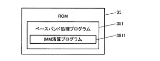
図9は、ベースバンド処理回路部30のROM35に格納されたデータの一例を示す図である。ROM35には、測位演算部33により読み出され、ベースバンド処理(図13参照)として実行されるベースバンド処理プログラム351が記憶されている。また、ベースバンド処理プログラム351には、IMM演算処理(図2及び図3参照)として実行されるIMM演算プログラム3511がサブルーチンとして含まれている。
3-2. Data Configuration FIG. 9 is a diagram illustrating an example of data stored in the
ベースバンド処理とは、測位演算部33が、IMM演算処理を行って出力位置を決定し、当該出力位置をホストCPU50に出力する処理である。ベースバンド処理については、フローチャートを用いて詳細に後述する。
The baseband process is a process in which the
IMM演算処理とは、測位演算部33が、複数のKFモデルに基づくKF処理の処理結果を、算出・更新したモデル確率で合成することで、出力位置を決定する処理である。本実施例では、図11に示すように、携帯型電話機1の移動状態を示すKFモデルとして、停止状態にあることを示す定点KFモデルと、等速移動状態にあることを示す等速度KFモデルと、定加速度状態にあることを示す定加速度KFモデルとの3種類のKFモデルの処理結果に基づくIMM演算を行って現在位置を測位する。
The IMM calculation process is a process in which the
図10は、ベースバンド処理回路部30のRAM37に格納されるデータの一例を示す図である。RAM37には、IMMパラメータデータ371と、捕捉衛星別メジャメントデータ373と、出力位置データ375とが記憶される。
FIG. 10 is a diagram illustrating an example of data stored in the
IMMパラメータデータ371は、IMM演算処理において用いられるIMM演算の各種パラメータ(以下、「IMMパラメータ」と称す。)の値が記憶されたデータであり、IMM演算処理において測位演算部33により更新される。
The
図12は、捕捉衛星別メジャメントデータ373のデータ構成例を示す図である。捕捉衛星別メジャメントデータ373は、IMM演算処理に使用するメジャメント情報についてのデータであり、捕捉衛星3731と、メジャメント実測値3733と、メジャメント予測値3735とが対応付けて記憶される。捕捉衛星3731には、当該捕捉衛星の番号が記憶され、メジャメント実測値3733及びメジャメント予測値3735には、当該捕捉衛星から受信したGPS衛星信号の受信周波数やコード位相の実測値及び予測値がそれぞれ記憶される。
FIG. 12 is a diagram illustrating a data configuration example of
例えば、捕捉衛星「S1」についてのメジャメント実測値は、受信周波数が「SFreq1」、コード位相が「SCP1」であり、メジャメント予測値は、受信周波数が「EFreq1」、コード位相が「ECP1」である。 For example, the measurement actual value for the acquisition satellite “S1” has the reception frequency “SFreq1” and the code phase “SCP1”, and the measurement prediction value has the reception frequency “EFreq1” and the code phase “ECP1”. .
IMM演算処理では、測位演算部33は、メジャメント取得演算部32により取得演算されたGPS衛星信号の受信周波数及びコード位相の情報を、メジャメント実測値として取得する。また、測位演算部33は、KF処理において予測演算により予測した状態ベクトルの予測値と観測行列とを用いてGPS衛星信号の受信周波数及びコード位相の情報を予測して、メジャメント予測値とする。
In the IMM calculation process, the
出力位置データ375は、ホストCPU50に出力する位置として決定された出力位置のデータであり、IMM演算処理において測位演算部33により更新される。
The
3−3.処理の流れ
図13は、測位演算部33によりROM35に記憶されているベースバンド処理プログラム351が読み出されて実行されることで、携帯型電話機1において実行されるベースバンド処理の流れを示すフローチャートである。ベースバンド処理は、RF受信回路部21によるGPS衛星信号の受信と併せて、測位演算部33が、操作部60に測位開始指示の操作がなされたことを検出した場合に実行を開始する処理であり、各種アプリケーションの実行といった各種の処理と並行して行われる処理である。
3-3. Processing Flow FIG. 13 is a flowchart showing the flow of baseband processing executed in the
尚、携帯型電話機1の電源のON/OFFとGPSの起動/停止とを連動させ、携帯型電話機1の電源投入操作を検出した場合に処理の実行を開始させることにしてもよい。原則として、測位演算は「1秒」毎に行われるものとする。また、特に説明しないが、以下のベースバンド処理の実行中は、GPSアンテナ10によるRF信号の受信や、RF受信回路部21によるIF信号へのダウンコンバート、メジャメント取得演算部32によるGPS衛星信号の受信周波数やコード位相の情報の取得・算出等が随時行われている状態にあるものとする。
It should be noted that the power on / off of the
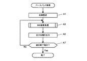
先ず、測位演算部33は、初期設定を行う(ステップA1)。具体的には、IMMパラメータを初期化し、RAM37のIMMパラメータデータ371に記憶させる。次いで、測位演算部33は、ROM35に記憶されているIMM演算プログラム3511を読み出して実行することで、IMM演算処理を行う(ステップA3)。
First, the
ステップA3のIMM演算処理では、測位演算部33は、図2及び図3のフローチャートに従って処理を実行する。この場合において、測位演算部33は、携帯型電話機1の3次元の位置「(x,y,z)」、3次元の速度「(u,v,w)」、3次元の加速度「(ax,ay,az)」、クロックバイアス「b」及びクロックドリフト「d」を成分とする次式(20)で表される11次元の状態ベクトル「X」を用いてIMM演算を行う。
![]()
![]()
また、測位演算部33は、定点KFモデル用の状態遷移行列として次式(21)で与えられる「φ1」、等速度KFモデル用の状態遷移行列として次式(22)で与えられる「φ2」、定加速度KFモデル用の状態遷移行列として次式(23)で与えられる「φ3」を用いてKF処理を行う。
In addition, the
より具体的には、測位演算部33は、図2のIMM演算処理のステップS11における予測演算において、状態遷移行列「φ1」〜「φ3」を用いて、式(6)及び式(7)に従って状態ベクトル及び誤差共分散の予測値「X−:X− 1,X− 2,X− 3」及び「P−:P− 1,P− 2,P− 3」を算出する。尚、状態遷移行列は、11×11の行列であり、その行と列の並びは、式(20)の状態ベクトル「X」の成分の並びに対応している。
More specifically, the
式(21)の状態遷移行列「φ1」では、3次元の位置に対応する3×3の行列部分の対角成分は「1」になっているが、3次元の速度及び加速度に対応する6×6の行列部分の成分は全て「0」になっており、携帯型電話機1が停止状態にあることを表していることがわかる。
In the state transition matrix “φ 1 ” in Expression (21), the diagonal component of the 3 × 3 matrix portion corresponding to the three-dimensional position is “1”, but it corresponds to the three-dimensional velocity and acceleration. The components of the 6 × 6 matrix portion are all “0”, which indicates that the
式(22)の状態遷移行列「φ2」では、3次元の位置及び速度に対応する6×6の行列部分の対角成分は「1」になっているが、3次元の加速度に対応する3×3の行列部分の成分は全て「0」になっており、携帯型電話機1が等速移動状態にあることを表していることがわかる。
In the state transition matrix “φ 2 ” in Expression (22), the diagonal component of the 6 × 6 matrix portion corresponding to the three-dimensional position and velocity is “1”, but it corresponds to the three-dimensional acceleration. All the components of the 3 × 3 matrix portion are “0”, which indicates that the
式(23)の状態遷移行列「φ3」では、3次元の位置、速度及び加速度に対応する9×9の行列部分の対角成分が「1」となっており、携帯型電話機1が定加速度状態にあることを表していることがわかる。
In the state transition matrix “φ 3 ” in Expression (23), the diagonal component of the 9 × 9 matrix portion corresponding to the three-dimensional position, velocity, and acceleration is “1”, and the
また、測位演算部33は、定点KFモデル、等速度KFモデル及び定加速度KFモデルそれぞれについて、次式(24)で表される観測行列「H」を用いて計算を行う。
より具体的には、測位演算部33は、図2のIMM演算処理のステップS15において、観測行列「H」を用いてメジャメント予測値「HX−:H1X− 1,H2X− 2,H3X− 3」を算出する。また、ステップS17の補正演算において、観測行列「H」を用いて式(8)〜式(10)に従って状態ベクトル及び誤差共分散の補正値「X:X1,X2,X3」及び「P:P1,P2,P3」を算出する。そして、ステップS19及びS21において、観測行列「H」を用いて式(11)及び式(12)に従って尤度指標値「Vx:Vx1,Vx2,Vx3」及び重み係数「β:β1,β2,β3」を算出する。
More specifically, the
ここで、観測行列「H」に含まれる「Dx」、「Dy」及び「Dz」は、次式(25−1)〜(25−3)でそれぞれ与えられる。
但し、「xu」、「yu」及び「zu」は、それぞれKF処理の予測演算により予測された携帯型電話機1の予測位置の3次元の成分をそれぞれ示しており、「xs」、「ys」及び「zs」は、観測対象とするGPS衛星の位置の3次元の成分をそれぞれ示している。また、「R」は、携帯型電話機1の予測位置と観測対象とするGPS衛星の位置間の距離を示している。
However, “x u ”, “y u ”, and “z u ” respectively indicate the three-dimensional components of the predicted position of the
そして、測位演算部33は、定点KFモデル、等速度KFモデル及び定加速度KFモデルそれぞれについてステップS19で算出した尤度指標値「Vx」の相対値「Vx1−Vx2」、「Vx2−Vx1」、「Vx1−Vx3」、「Vx3−Vx1」、「Vx2−Vx3」及び「Vx3−Vx2」を算出し(ステップS25)、これらの相対値と、ステップS21で算出した重み係数「β:β1,β2,β3」と、ステップS3で算出した規格化定数「CN:C1,C2,C3」とを用いて式(13−2)に従ってモデル確率「μ:μ1,μ2,μ3」を算出する(ステップS27、S29)。
Then, the
そして、測位演算部33は、算出したモデル確率「μ:μ1,μ2,μ3」を用いて、式(16)及び式(17)に従って状態ベクトル「X:X1,X2,X3」及び誤差共分散「P:P1,P2,P3」を算出することで、状態ベクトルの出力値「X」及び誤差共分散の出力値「P」を決定する(ステップS31)。
Then, the
ステップA3でIMM演算処理を行った後、測位演算部33は、IMM演算処理で決定した状態ベクトルの出力値「X」に含まれる携帯型電話機1の3次元の位置「(x,y,z)」を出力位置に決定し、ホストCPU50に出力する(ステップA5)。
After performing the IMM calculation process in step A3, the
その後、測位演算部33は、操作部60を介してユーザにより測位終了指示がなされたか否かを判定し(ステップA7)、なされなかったと判定した場合は(ステップA7;No)、ステップA3に戻る。また、測位終了指示がなされたと判定した場合は(ステップA7;Yes)、ベースバンド処理を終了する。
Thereafter, the
4.作用効果
本実施形態によれば、カルマンフィルタ処理それぞれの尤度指標値「Vx」が算出され、この尤度指標値「Vx」のカルマンフィルタ処理間の相対値が算出される。そして、算出された相対値を用いてカルマンフィルタ処理それぞれのモデル確率「μ」が算出され、このモデル確率「μ」を用いてカルマンフィルタ処理それぞれの処理結果が合成されることで測位位置が決定される。
4). Effects According to the present embodiment, the likelihood index value “Vx” of each Kalman filter process is calculated, and the relative value between the Kalman filter processes of the likelihood index value “Vx” is calculated. Then, the model probability “μ” of each Kalman filter process is calculated using the calculated relative value, and the positioning position is determined by combining the process results of each Kalman filter process using this model probability “μ”. .
ここで、尤度指標値「Vx」とは、カルマンフィルタの入力値となる外部観測量の尤度「λ」を算出するための尤度関数の指数部分のことを指す。IMM演算におけるモデル確率「μ」は、尤度指標値「Vx」を用いて算出した外部観測量の尤度「λ」を基に算出することができるが、尤度指標値「Vx」が非常に小さな値である場合には、計算機で計算しようとしても尤度「λ」の返し値が「0」になってしまい、モデル確率「μ」を正しく求めることができない。 Here, the likelihood index value “Vx” refers to the exponent part of the likelihood function for calculating the likelihood “λ” of the external observation amount that is the input value of the Kalman filter. The model probability “μ” in the IMM calculation can be calculated based on the likelihood “λ” of the external observation amount calculated using the likelihood index value “Vx”, but the likelihood index value “Vx” is very high. If the value is too small, the return value of the likelihood “λ” becomes “0” even if it is calculated by a computer, and the model probability “μ” cannot be obtained correctly.
この問題を解決するため、尤度指標値「Vx」をそのまま用いるのではなく、複数のカルマンフィルタ処理間の尤度指標値「Vx」の相対値を用いる。これは、個々の尤度指標値「Vx」が非常に小さな値であったとしても、尤度指標値「Vx」の相対値は概ね「0」の近傍の値となり、指数関数に当該相対値を与えて計算すると「0」とはならない点に着目したものである。かかる原理により、モデル確率「μ」を正しく算出することが可能となり、その結果、正確な測位位置の算出を実現し得る。 In order to solve this problem, the likelihood index value “Vx” is not used as it is, but the relative value of the likelihood index value “Vx” between a plurality of Kalman filter processes is used. This is because even if each likelihood index value “Vx” is a very small value, the relative value of the likelihood index value “Vx” is a value in the vicinity of “0”, and the relative value is represented in the exponential function. Note that the calculation does not become “0” when given. With this principle, it is possible to correctly calculate the model probability “μ”, and as a result, accurate positioning position calculation can be realized.
5.変形例
5−1.電子機器
本発明は、測位装置を備えた電子機器であれば何れの電子機器にも適用可能である。例えば、ノート型パソコンやPDA(Personal Digital Assistant)、カーナビゲーション装置等についても同様に適用可能である。
5. Modified example 5-1. Electronic Device The present invention can be applied to any electronic device provided that it has a positioning device. For example, the present invention can be similarly applied to a notebook personal computer, a PDA (Personal Digital Assistant), a car navigation device, and the like.
5−2.衛星測位システム
上述した実施形態では、衛星測位システムとしてGPSを例に挙げて説明したが、WAAS(Wide Area Augmentation System)、QZSS(Quasi Zenith Satellite System)、GLONASS(GLObal NAvigation Satellite System)、GALILEO等の他の衛星測位システムであってもよい。
5-2. Satellite positioning system In the above-described embodiment, the GPS has been described as an example of the satellite positioning system. Other satellite positioning systems may be used.
5−3.処理の分化
測位演算部33が実行する処理の一部又は全部を、ホストCPU50が実行することにしてもよい。例えば、メジャメント取得演算部32から取得したメジャメント実測値を用いて、ホストCPU50がIMM演算を行って出力位置を決定し、当該出力位置を表示部70に表示させる。
5-3. Differentiation of Processing The
1 携帯型電話機 、 10 GPSアンテナ、 20 GPS受信部、
21 RF受信回路部、 30 ベースバンド処理回路部、 31 演算制御部、
32 メジャメント取得演算部、 33 測位演算部、 35 ROM、
37 RAM、 40 TCXO、 50 ホストCPU、 60 操作部、
70 表示部、 80 携帯電話用アンテナ、 90 携帯電話用無線通信回路部、
100 ROM、 110 RAM
1 mobile phone, 10 GPS antenna, 20 GPS receiver,
21 RF receiving circuit section, 30 baseband processing circuit section, 31 arithmetic control section,
32 measurement acquisition calculation unit, 33 positioning calculation unit, 35 ROM,
37 RAM, 40 TCXO, 50 host CPU, 60 operation unit,
70 display unit, 80 antenna for mobile phone, 90 wireless communication circuit unit for mobile phone,
100 ROM, 110 RAM
Claims (6)
当該カルマンフィルタ処理の状態ベクトル及び誤差共分散と所与のメジャメント実測値とに基づいて、前記カルマンフィルタ処理それぞれについての、当該メジャメント実測値の尤度を示す尤度関数の指数部分を示す尤度指標値(Vx 1 ,Vx 2 ,…Vx j )を算出することと、
前記算出された尤度指標値の前記カルマンフィルタ処理間の相対値(当該カルマンフィルタ処理jに関する相対値は(Vx 1 −Vx j ),(Vx 2 −Vx j ),…(Vx n −Vx j ):但しnはカルマンフィルタ処理の総数)を算出することと、
以下の(式1)を用いて前記カルマンフィルタ処理それぞれの前記モデル確率(μ 1 ,μ 2 ,…μ j )を算出することと、
前記算出されたモデル確率を用いて前記カルマンフィルタ処理それぞれの処理結果を合成することで測位位置を決定することと、
を含む測位方法。
A likelihood index value indicating an exponent part of a likelihood function indicating the likelihood of the measurement actual value for each of the Kalman filter processing based on the state vector and error covariance of the Kalman filter processing and a given measurement actual value Calculating (Vx 1 , Vx 2 ,... Vx j ) ;
Relative values of the calculated likelihood index values between the Kalman filter processes ( relative values for the Kalman filter process j are (Vx 1 −Vx j ), (Vx 2 −Vx j ),... (Vx n −Vx j )): Where n is the total number of Kalman filter processes) ,
Calculating the model probabilities (μ 1 , μ 2 ,... Μ j ) for each of the Kalman filter processes using (Equation 1) below ;
Determining a positioning position by combining the processing results of the Kalman filter processes using the calculated model probabilities;
Positioning method including.
請求項1に記載の測位方法。 To calculate the model probability, the method comprising the relative value to determine whether it is within a predetermined range, when it is determined that the is within a predetermined range, using the (Formula 1) and to calculate the model probability Te,
The positioning method according to claim 1 .
請求項2に記載の測位方法。 The calculation of the model probability is to set the model probability to “1” when the relative value is equal to or higher than the upper limit of the predetermined range, and to set the model probability to “1” when the relative value is lower than the lower limit of the predetermined range. Including,
The positioning method according to claim 2 .
請求項1〜3の何れか一項に記載の測位方法。 In the plurality of Kalman filter processes, the Kalman filter process based on the assumption that the positioning device is in the stopped state, the Kalman filter process based on the constant speed movement state, and the constant acceleration state are used. Including at least three types of Kalman filter processing and Kalman filter processing based on
The positioning method as described in any one of Claims 1-3 .
当該カルマンフィルタ処理の状態ベクトル及び誤差共分散と所与のメジャメント実測値とに基づいて、前記カルマンフィルタ処理それぞれについての、当該メジャメント実測値の尤度を示す尤度関数の指数部分を示す尤度指標値(Vx 1 ,Vx 2 ,…Vx j )を算出する指標値算出部と、
前記算出された尤度指標値の前記カルマンフィルタ処理間の相対値((Vx 1 −Vx j ),(Vx 2 −Vx j ),…(Vx n −Vx j ):但しnはカルマンフィルタ処理の総数)を算出する相対値算出部と、
以下の(式2)を用いて前記カルマンフィルタ処理それぞれの前記モデル確率(μ 1 ,μ 2 ,…μ j )を算出するモデル確率算出部と、
前記算出されたモデル確率を用いて前記カルマンフィルタ処理それぞれの処理結果を合成することで測位位置を決定する測位位置決定部と、
を備えた測位装置。
A likelihood index value indicating an exponent part of a likelihood function indicating the likelihood of the measurement actual value for each of the Kalman filter processing based on the state vector and error covariance of the Kalman filter processing and a given measurement actual value An index value calculation unit for calculating (Vx 1 , Vx 2 ,... Vx j ) ;
Relative values of the calculated likelihood index values between the Kalman filter processes ((Vx 1 −Vx j ), (Vx 2 −Vx j ),... (Vx n −Vx j ): where n is the total number of Kalman filter processes) A relative value calculation unit for calculating
A model probability calculation unit that calculates the model probabilities (μ 1 , μ 2 ,... Μ j ) of each of the Kalman filter processes using (Equation 2) below ;
A positioning position determining unit that determines a positioning position by combining the processing results of the Kalman filter processes using the calculated model probability;
Positioning device equipped with.
Priority Applications (2)
| Application Number | Priority Date | Filing Date | Title |
|---|---|---|---|
| JP2008094954A JP5266846B2 (en) | 2008-04-01 | 2008-04-01 | POSITIONING METHOD, PROGRAM, AND POSITIONING DEVICE |
| US12/413,076 US20090243920A1 (en) | 2008-04-01 | 2009-03-27 | Positioning method, program, and positioning apparatus |
Applications Claiming Priority (1)
| Application Number | Priority Date | Filing Date | Title |
|---|---|---|---|
| JP2008094954A JP5266846B2 (en) | 2008-04-01 | 2008-04-01 | POSITIONING METHOD, PROGRAM, AND POSITIONING DEVICE |
Publications (2)
| Publication Number | Publication Date |
|---|---|
| JP2009250619A JP2009250619A (en) | 2009-10-29 |
| JP5266846B2 true JP5266846B2 (en) | 2013-08-21 |
Family
ID=41116311
Family Applications (1)
| Application Number | Title | Priority Date | Filing Date |
|---|---|---|---|
| JP2008094954A Expired - Fee Related JP5266846B2 (en) | 2008-04-01 | 2008-04-01 | POSITIONING METHOD, PROGRAM, AND POSITIONING DEVICE |
Country Status (2)
| Country | Link |
|---|---|
| US (1) | US20090243920A1 (en) |
| JP (1) | JP5266846B2 (en) |
Families Citing this family (8)
| Publication number | Priority date | Publication date | Assignee | Title |
|---|---|---|---|---|
| CN102663771A (en) * | 2012-03-14 | 2012-09-12 | 北京航空航天大学 | Interactive multi-model estimation method based on covariance intersection |
| US9513374B2 (en) * | 2012-12-10 | 2016-12-06 | Texas Instruments Incorporated | Measurement error covariance in GNSS receiver circuitry, pseudoranges, reference position |
| KR20160002178A (en) * | 2014-06-30 | 2016-01-07 | 현대자동차주식회사 | Apparatus and method for self-localization of vehicle |
| CN107993257B (en) * | 2017-12-28 | 2020-05-19 | 中国科学院西安光学精密机械研究所 | Intelligent IMM Kalman filtering feedforward compensation target tracking method and system |
| US11119187B2 (en) * | 2019-02-19 | 2021-09-14 | GM Global Technology Operations LLC | Resolution of doppler ambiguity in a radar system through tracking |
| US11979851B2 (en) | 2019-06-18 | 2024-05-07 | Telefonaktiebolaget Lm Ericsson (Publ) | User equipment kinematic state estimation |
| CN110426671B (en) * | 2019-07-04 | 2023-05-12 | 重庆邮电大学 | IMM target tracking method and device based on model probability real-time correction in WSN |
| WO2022018487A1 (en) * | 2020-07-22 | 2022-01-27 | Telefonaktiebolaget Lm Ericsson (Publ) | State estimation for aerial user equipment (ues) operating in a wireless network |
Family Cites Families (9)
| Publication number | Priority date | Publication date | Assignee | Title |
|---|---|---|---|---|
| US6609080B1 (en) * | 1999-11-22 | 2003-08-19 | Nokia Mobile Phones Ltd | Multiple-model navigation filter with hybrid positioning |
| US6732050B2 (en) * | 2001-05-23 | 2004-05-04 | Nokia Mobile Phones Ltd | Two-stage interacting multiple models filter for use in a global positioning system |
| JP4348535B2 (en) * | 2004-03-24 | 2009-10-21 | 三菱電機株式会社 | Target tracking device |
| GB0504889D0 (en) * | 2005-03-08 | 2005-08-17 | Advanced System Architecture L | Management of tracking models suitable for demanding defence scenarios |
| JP4897806B2 (en) * | 2006-06-13 | 2012-03-14 | ビ−エイイ− システムズ パブリック リミテッド カンパニ− | Method, network and computer program for tracking goals |
| US7551133B2 (en) * | 2007-04-05 | 2009-06-23 | Sirf Technology, Inc. | GPS navigation using interacting multiple model (IMM) estimator and probabilistic data association filter (PDAF) |
| JP5089281B2 (en) * | 2007-07-26 | 2012-12-05 | 三菱電機株式会社 | State estimation device and state estimation method |
| JP5251090B2 (en) * | 2007-11-30 | 2013-07-31 | セイコーエプソン株式会社 | POSITIONING METHOD, PROGRAM, AND POSITIONING DEVICE |
| JP5034935B2 (en) * | 2007-12-27 | 2012-09-26 | セイコーエプソン株式会社 | POSITIONING METHOD, PROGRAM, POSITIONING DEVICE, AND ELECTRONIC DEVICE |
-
2008
- 2008-04-01 JP JP2008094954A patent/JP5266846B2/en not_active Expired - Fee Related
-
2009
- 2009-03-27 US US12/413,076 patent/US20090243920A1/en not_active Abandoned
Also Published As
| Publication number | Publication date |
|---|---|
| JP2009250619A (en) | 2009-10-29 |
| US20090243920A1 (en) | 2009-10-01 |
Similar Documents
| Publication | Publication Date | Title |
|---|---|---|
| JP5034935B2 (en) | POSITIONING METHOD, PROGRAM, POSITIONING DEVICE, AND ELECTRONIC DEVICE | |
| JP5266846B2 (en) | POSITIONING METHOD, PROGRAM, AND POSITIONING DEVICE | |
| JP5186873B2 (en) | POSITIONING METHOD, PROGRAM, POSITIONING DEVICE, AND ELECTRONIC DEVICE | |
| US8373592B2 (en) | Initial position determination method, positioning method, and positioning apparatus | |
| US7777673B2 (en) | Positioning method, positioning device, and program | |
| JP5186874B2 (en) | POSITIONING METHOD, PROGRAM, POSITIONING DEVICE, AND ELECTRONIC DEVICE | |
| JP5050904B2 (en) | Current position positioning method and positioning device | |
| JP2010151459A (en) | Method and device for calculating position | |
| JP5439826B2 (en) | Position calculation method and position calculation apparatus | |
| US7928902B2 (en) | Positioning method, positioning device, and electronic instrument | |
| US9253751B2 (en) | Method of calculating movement speed and device for calculating movement speed | |
| US20100302030A1 (en) | Initial position determining method, positioning calculating method, and position calculating device | |
| US8670927B2 (en) | Positioning method, program, positioning device, and electronic apparatus | |
| JP2010175426A (en) | Method and device for calculating out position | |
| US20120119945A1 (en) | Satellite orbital data compression method, satellite orbital data providing method, satellite orbital data expansion method, server, and positioning apparatus | |
| US7961142B2 (en) | Present position locating method, positioning device, and electronic instrument | |
| JP5332333B2 (en) | POSITIONING METHOD, PROGRAM, AND POSITIONING DEVICE | |
| JP2013195324A (en) | Prediction ephemeris generation method | |
| JP2009229293A (en) | Positioning method, program, and positioning device | |
| JP2009103489A (en) | Positioning method, program, positioning device, and electronic device | |
| JP5521284B2 (en) | Positioning method and positioning device | |
| JP2008281551A (en) | Present position locating method and program, storage medium, positioning device, and electronic equipment | |
| JP2013036958A (en) | Halt/movement determining method |
Legal Events
| Date | Code | Title | Description |
|---|---|---|---|
| A621 | Written request for application examination |
Free format text: JAPANESE INTERMEDIATE CODE: A621 Effective date: 20110324 |
|
| A977 | Report on retrieval |
Free format text: JAPANESE INTERMEDIATE CODE: A971007 Effective date: 20120524 |
|
| A131 | Notification of reasons for refusal |
Free format text: JAPANESE INTERMEDIATE CODE: A131 Effective date: 20120605 |
|
| A521 | Written amendment |
Free format text: JAPANESE INTERMEDIATE CODE: A523 Effective date: 20120806 |
|
| TRDD | Decision of grant or rejection written | ||
| A01 | Written decision to grant a patent or to grant a registration (utility model) |
Free format text: JAPANESE INTERMEDIATE CODE: A01 Effective date: 20130409 |
|
| A61 | First payment of annual fees (during grant procedure) |
Free format text: JAPANESE INTERMEDIATE CODE: A61 Effective date: 20130422 |
|
| R150 | Certificate of patent or registration of utility model |
Free format text: JAPANESE INTERMEDIATE CODE: R150 Ref document number: 5266846 Country of ref document: JP Free format text: JAPANESE INTERMEDIATE CODE: R150 |
|
| S531 | Written request for registration of change of domicile |
Free format text: JAPANESE INTERMEDIATE CODE: R313531 |
|
| R350 | Written notification of registration of transfer |
Free format text: JAPANESE INTERMEDIATE CODE: R350 |
|
| LAPS | Cancellation because of no payment of annual fees |