JP5265581B2 - Rear wheel steering three wheel scooter - Google Patents
Rear wheel steering three wheel scooter Download PDFInfo
- Publication number
- JP5265581B2 JP5265581B2 JP2009552721A JP2009552721A JP5265581B2 JP 5265581 B2 JP5265581 B2 JP 5265581B2 JP 2009552721 A JP2009552721 A JP 2009552721A JP 2009552721 A JP2009552721 A JP 2009552721A JP 5265581 B2 JP5265581 B2 JP 5265581B2
- Authority
- JP
- Japan
- Prior art keywords
- scooter
- wheel
- handle assembly
- shaft
- foot support
- Prior art date
- Legal status (The legal status is an assumption and is not a legal conclusion. Google has not performed a legal analysis and makes no representation as to the accuracy of the status listed.)
- Expired - Fee Related
Links
Images


Classifications
-
- B—PERFORMING OPERATIONS; TRANSPORTING
- B62—LAND VEHICLES FOR TRAVELLING OTHERWISE THAN ON RAILS
- B62K—CYCLES; CYCLE FRAMES; CYCLE STEERING DEVICES; RIDER-OPERATED TERMINAL CONTROLS SPECIALLY ADAPTED FOR CYCLES; CYCLE AXLE SUSPENSIONS; CYCLE SIDE-CARS, FORECARS, OR THE LIKE
- B62K17/00—Cycles not otherwise provided for
-
- B—PERFORMING OPERATIONS; TRANSPORTING
- B62—LAND VEHICLES FOR TRAVELLING OTHERWISE THAN ON RAILS
- B62K—CYCLES; CYCLE FRAMES; CYCLE STEERING DEVICES; RIDER-OPERATED TERMINAL CONTROLS SPECIALLY ADAPTED FOR CYCLES; CYCLE AXLE SUSPENSIONS; CYCLE SIDE-CARS, FORECARS, OR THE LIKE
- B62K3/00—Bicycles
- B62K3/002—Bicycles without a seat, i.e. the rider operating the vehicle in a standing position, e.g. non-motorized scooters; non-motorized scooters with skis or runners
-
- B—PERFORMING OPERATIONS; TRANSPORTING
- B62—LAND VEHICLES FOR TRAVELLING OTHERWISE THAN ON RAILS
- B62D—MOTOR VEHICLES; TRAILERS
- B62D61/00—Motor vehicles or trailers, characterised by the arrangement or number of wheels, not otherwise provided for, e.g. four wheels in diamond pattern
- B62D61/06—Motor vehicles or trailers, characterised by the arrangement or number of wheels, not otherwise provided for, e.g. four wheels in diamond pattern with only three wheels
-
- B—PERFORMING OPERATIONS; TRANSPORTING
- B62—LAND VEHICLES FOR TRAVELLING OTHERWISE THAN ON RAILS
- B62K—CYCLES; CYCLE FRAMES; CYCLE STEERING DEVICES; RIDER-OPERATED TERMINAL CONTROLS SPECIALLY ADAPTED FOR CYCLES; CYCLE AXLE SUSPENSIONS; CYCLE SIDE-CARS, FORECARS, OR THE LIKE
- B62K5/00—Cycles with handlebars, equipped with three or more main road wheels
- B62K5/02—Tricycles
-
- B—PERFORMING OPERATIONS; TRANSPORTING
- B62—LAND VEHICLES FOR TRAVELLING OTHERWISE THAN ON RAILS
- B62K—CYCLES; CYCLE FRAMES; CYCLE STEERING DEVICES; RIDER-OPERATED TERMINAL CONTROLS SPECIALLY ADAPTED FOR CYCLES; CYCLE AXLE SUSPENSIONS; CYCLE SIDE-CARS, FORECARS, OR THE LIKE
- B62K5/00—Cycles with handlebars, equipped with three or more main road wheels
- B62K5/08—Cycles with handlebars, equipped with three or more main road wheels with steering devices acting on two or more wheels
-
- B—PERFORMING OPERATIONS; TRANSPORTING
- B62—LAND VEHICLES FOR TRAVELLING OTHERWISE THAN ON RAILS
- B62M—RIDER PROPULSION OF WHEELED VEHICLES OR SLEDGES; POWERED PROPULSION OF SLEDGES OR SINGLE-TRACK CYCLES; TRANSMISSIONS SPECIALLY ADAPTED FOR SUCH VEHICLES
- B62M1/00—Rider propulsion of wheeled vehicles
Landscapes
- Engineering & Computer Science (AREA)
- Mechanical Engineering (AREA)
- Chemical & Material Sciences (AREA)
- Combustion & Propulsion (AREA)
- Transportation (AREA)
- Automatic Cycles, And Cycles In General (AREA)
- Motorcycle And Bicycle Frame (AREA)
- Steering Devices For Bicycles And Motorcycles (AREA)
Description
本発明は、車輪付の乗り物全般に関し、詳しくは、三輪であって、単一の前輪と一対の小径の後輪とを特に備える後輪操舵のスクータに関する。同スクータは運転者の操舵により、旋回軸上に取り付けられた後輪に対する車体の横揺れや傾斜によって、後輪の角度のあるヨーイングを生じるように特に適合されている。 The present invention relates to a vehicle with wheels in general, and more particularly to a rear wheel steering scooter that is a three-wheeled vehicle and particularly includes a single front wheel and a pair of small-diameter rear wheels. The scooter is particularly adapted to produce yawing with an angle of the rear wheel by the rolling and tilting of the vehicle body with respect to the rear wheel mounted on the turning shaft by the driver's steering.
スクータは従来の技術においてよく知られるとともに、幅広い種類の構成を入手可能であり、それぞれの構成は、乗員または操縦者に、他のスクータ構成では行えない特定の操作を行える明らかな利点を備えている。例えばIbarraによる特許文献1によれば、小径の一対の車輪によって後部を支持され、かつ、大径の一つの前輪によって前端部を支持された、延伸された踏み板を備えるスクータが開示されている。このスクータは、ハンドルアセンブリを介して操縦者が操舵できる、旋回可能な前輪を介する明確な操舵性能を備えている。この踏み板は、後輪の後部に位置する上方に傾斜した扁平部を含み、同扁平部は操縦者が「ウイリー」をするような扁平部上の運転者の足踏みに応じて、スクータを上方へ縦揺れさせる角度に配向するものであって、スクータが物体を超える跳躍を可能にしている。 Scooters are well known in the prior art, and a wide variety of configurations are available, each with the obvious advantages that allow the occupant or pilot to perform certain operations that are not possible with other scooter configurations. Yes. For example, Patent Document 1 by Ibarra discloses a scooter including an extended footboard having a rear portion supported by a pair of small-diameter wheels and a front end portion supported by one large-diameter front wheel. The scooter has a clear steering performance via a turnable front wheel that can be steered by a driver via a handle assembly. The footboard includes an upwardly inclined flat portion located at the rear of the rear wheel, and the flat portion moves the scooter upward in response to the driver's stepping on the flat portion where the driver performs a “wheelie”. It is oriented at the angle of pitching, allowing the scooter to jump over the object.
Hinderhoferの特許文献2に開示されるフレームアセンブリを備えたスクータは、そのフレームアセンブリの後部に踏み板を備え、スクータの前端部に大径の前輪を備えている。この踏み板の後部は、少なくとも一つの操舵できない、好ましくは踏み板の下に設けられた後輪に支持されている。また、このスクータは、階段や曲がり道のような水平でない地形を越える滑走運動を容易にするための複数の転がり表面を提供するインライン形状に配置された複数の後輪を備えている。スクータの操舵は、乗員が前輪を旋回させるハンドルアセンブリによって容易にされ、このため、従来の方法でスクータをスチールする。 A scooter equipped with a frame assembly disclosed in Japanese Patent Application Laid-Open No. 2004-228867 includes a foot plate at the rear of the frame assembly and a large-diameter front wheel at the front end of the scooter. The rear part of the tread is supported by at least one non-steerable, preferably rear wheel provided under the tread. The scooter also includes a plurality of rear wheels arranged in an in-line configuration that provides a plurality of rolling surfaces to facilitate a sliding motion over non-horizontal terrain such as stairs and turns. Steering of the scooter is facilitated by a handle assembly that allows the occupant to turn the front wheel, and thus steers the scooter in a conventional manner.
Rappaportの特許文献3に開示されるデュアル踏み板スクータは、相対的に大径であってフレームに接続される一つの前輪を備えた三輪配置を有している。このフレームは2つの枝を形成するように二股に分かれる配置で後方へ延伸し、それぞれの枝は単一の後輪に支持されている。このそれぞれの枝は、後輪によってその後端部で支持されるほぼ水平に指向される踏み板を備えている。操縦者は、スクータを前方へ推進するために地面に接触して地面を押す間、その踏み板の一方の上で片足を休憩させることができる。スクータの操舵は、スクータの操舵のためのハンドルバーアセンブリによって旋回可能な前輪によってもたらされる。 The dual footboard scooter disclosed in Patent Document 3 of Rappaport has a three-wheel arrangement with one front wheel having a relatively large diameter and connected to a frame. The frame extends rearward in a bifurcated arrangement to form two branches, each branch supported by a single rear wheel. Each branch has a substantially horizontally oriented tread that is supported at its rear end by a rear wheel. The operator can rest one foot on one of its treads while touching and pushing the ground to propel the scooter forward. Scooter steering is provided by a front wheel that is pivotable by a handlebar assembly for scooter steering.
Beleskiの特許文献4に開示される「キャンバ乗物」として構成される三輪のスクータは、単一の操舵可能な前輪と、分岐した後アーム上に設けられた一対の後輪を備えている。それぞれの後アームは、前側支柱に関節接合され、、その前側支柱から前輪が延びている。スクータの前方への運動は、ハンドルアセンブリによる操縦者の前輪の左右操舵によって生じるスクータの正弦曲線状の軌道を走行するような、操縦者の左右への交互の体重移動によって生じる。一側から他側への体重の移動と同時に起こる乗り物の操舵との組み合わせで、角運動量保存の原理の下に一連の加速を生じ、この結果、スクータの前方への運動が起きる。 A three-wheeled scooter configured as a “camber vehicle” disclosed in the Beleski patent document 4 includes a single steerable front wheel and a pair of rear wheels provided on a branched rear arm. Each rear arm is articulated to the front strut, and a front wheel extends from the front strut. The forward movement of the scooter is caused by alternating weight movement of the driver left and right, such as traveling on the scooter's sinusoidal path caused by left and right steering of the front wheel of the driver by the handle assembly. In combination with vehicle steering that coincides with the movement of body weight from one side to the other, a series of accelerations occur under the principle of angular momentum conservation, resulting in forward movement of the scooter.
従来の技術は、既に述べたスクータの配置構成に加えて、付加的な他のスクータ構成を備えている。従来の主なスクータは、操縦者がスクータを操舵できるハンドルバーアセンブリと組み合わされた旋回可能な前輪によって、スクータの方向制御を容易にする。さらに、従来のスクータ配置の多くは、前輪と後輪とが互いに相対的に大きな距離で離されるように構成されている、そのようなスクータは短径の旋回を行う能力を欠いている。さらに、従来のスクータ配置の多くは、スクータの安定化された姿勢において効果的な制御と操舵のために、乗員の両手によって握られることを要求される一対の左右の外方に延伸したアーム部材からなる従来の自転車のハンドルバーを備えている。 The prior art includes other scooter configurations in addition to the scooter arrangement described above. The main conventional scooter facilitates directional control of the scooter by a turnable front wheel combined with a handlebar assembly that allows the operator to steer the scooter. Furthermore, many of the conventional scooter arrangements are configured such that the front and rear wheels are separated from each other by a relatively large distance, such scooters lack the ability to make a short turn. Furthermore, many conventional scooter arrangements include a pair of left and right outwardly extending arm members that are required to be grasped by both occupant hands for effective control and steering in a stabilized position of the scooter. A conventional bicycle handlebar is provided.
理解されるように、操作を行える範囲を増加させるために、短径の旋回を含む可変の径での旋回の実行の性能を操縦者または乗員に提供するスクータが必要とされている。さらに、立ち位置にある乗員によって操縦されるが、乗員の手を用いたハンドルバーの回転によるスクータの操舵のための必要性が除外された、スクータが必要とされている。 As will be appreciated, there is a need for a scooter that provides the pilot or occupant with the ability to perform a turn with a variable diameter, including a short turn, in order to increase the range of operation. Further, there is a need for a scooter that is maneuvered by an occupant in a standing position but that eliminates the need for steering the scooter by rotating the handlebar using the occupant's hand.
加えて、成人だけではなく子供も、スクータから落ちるような怪我の危険なしにスクータを操縦するために、乗員の安定化またはバランスをとるための手段を提供するスクータが必要とされている。最後に、スクータの操作性能を向上させ、スクータの搬送と保管を容易にするために、簡単な構造、低コスト、小サイズ及び相対的に低重量のスクータが必要とされている。 In addition, there is a need for a scooter that provides a means to stabilize or balance an occupant so that not only adults but also children can maneuver the scooter without the risk of injury falling from the scooter. Finally, a simple structure, low cost, small size and relatively low weight scooter is needed to improve scooter operating performance and facilitate scooter transport and storage.
本発明は、三輪であって、相対的に短径の旋回を含む可変径の旋回を実行する性能を備える後輪操舵のスクータを提供することで、前述の必要性に特に取り組むものである。三輪であって後輪操舵のスクータは、車体の前端部に固定されて取り付けられた相対的に大径の前輪と、車体の後端に旋回可能に取り付けられた一対の小径の後輪とを備えている。一実施形態として、スクータは車体と関連した後輪の角度のあるヨーイングによって操舵可能に構成されている。このような角度のあるヨーイングは、車体の左右の旋回によって引き起こされる車体の非対称の荷重によって生じる。左右の横揺れは、車体の左側と右側の不均等な重さによって誘導され、次にスクータの操舵制御のための後輪の旋回または横揺れを引き起こす。 The present invention addresses this need in particular by providing a rear wheel steering scooter that has three wheels and is capable of performing a variable diameter turn including a relatively short turn. A three-wheel rear-wheel steering scooter has a relatively large-diameter front wheel fixed and attached to the front end of the vehicle body, and a pair of small-diameter rear wheels attached to the rear end of the vehicle body so as to be able to turn. I have. As an embodiment, the scooter is configured to be steerable by yawing with an angle of a rear wheel associated with the vehicle body. Such yawing with an angle is caused by an asymmetrical load on the vehicle body caused by a left-right turn of the vehicle body. Left and right rolls are induced by uneven weights on the left and right sides of the vehicle body, which in turn cause the rear wheels to turn or roll for steering control of the scooter.
最も広義においては、スクータは車体、車体の前端部に取り付けられた非旋回可能な(すなわち、非操舵可能な)前輪、及び車体の後端部に取り付けられた角度のあるヨーイング可能な一対の後輪を備える。車体は、前端と後端との間で延伸する長軸を定義する。車体は、ほぼ横方向に、乗員または操縦者の立ち位置を支持する前端部から後端部に延伸される支持アセンブリを備えている。 In the broadest sense, the scooter is a vehicle body, a non-turnable (ie non-steerable) front wheel attached to the front end of the vehicle body, and a pair of angled yawable rear wheels attached to the rear end of the vehicle body. Provide a ring. The vehicle body defines a long axis extending between the front end and the rear end. The vehicle body includes a support assembly that extends in a substantially lateral direction from a front end portion that supports a standing position of an occupant or a pilot to a rear end portion.
加えて、スクータは、支持アセンブリの前方に位置し、これより上方に延伸されたハンドルアセンブリを備えている。ハンドルアセンブリは、乗員の片方の手によって握られるためのグリップ部(すなわち、ハンドルグリップ)を備えた単一の垂直部材として構成されてもよい。一方、ハンドルアセンブリは、それぞれが従来のハンドルバーの構成に似たグリップ部、一対の左右の部材として構成されてもよい。その構成に関わらず、ハンドルアセンブリはスクータの乗員または操縦者の安定化のための手段を提供する。 In addition, the scooter includes a handle assembly positioned in front of the support assembly and extending upward therefrom. The handle assembly may be configured as a single vertical member with a grip portion (i.e., handle grip) for gripping by one hand of the occupant. On the other hand, the handle assembly may be configured as a grip portion and a pair of left and right members each resembling the configuration of a conventional handlebar. Regardless of its configuration, the handle assembly provides a means for stabilization of the scooter occupant or operator.
後輪は、好ましくは、互いに横方向に配置され、既に言及されたように、長軸に対する角度のあるヨーイングを生じるように特別に構成される。この点に関して、後輪は、ニュートラル位置とヨーイング位置との間で旋回またはヨーイングするように適合されている。ニュートラル位置においては、後輪の軸は、長軸に対して直交して配置される。ヨーイング位置においては、後輪は、長軸に対して直交しないように配置される。スクータの方向制御すなわち操舵は、後輪のニュートラル位置とヨーイング位置との間での角度のあるヨーイングの結果、単独で、すなわち主として実行される。 The rear wheels are preferably arranged laterally with respect to one another and are specially configured to produce an angled yaw relative to the major axis, as already mentioned. In this regard, the rear wheel is adapted to turn or yaw between a neutral position and a yawing position. In the neutral position, the axis of the rear wheel is arranged orthogonal to the long axis. In the yawing position, the rear wheel is arranged so as not to be orthogonal to the long axis. The direction control or steering of the scooter is carried out alone, i.e. mainly, as a result of the yawing with an angle between the neutral position and the yawing position of the rear wheel.
支持アセンブリは、好ましくは、長軸について左右に転がるように構成されている。このような横揺れは、支持アセンブリの右側と左側の一方の非対称な荷重によって生じることがある。非対称の荷重は、乗員による、乗員の足を使った不均等な重量かけのような、支持アセンブリの左側または右側に対する下方向への圧力により引き起こされる。支持アセンブリの非対称の荷重と横揺れは、スクータの旋回を引き起こす後輪の角度のあるヨーイング運動を引き起こす。 The support assembly is preferably configured to roll from side to side about the major axis. Such rolls can be caused by asymmetric loads on one of the right and left sides of the support assembly. Asymmetric loads are caused by downward pressure on the left or right side of the support assembly, such as uneven weighting by the occupant using the occupant's feet. The asymmetric loading and roll of the support assembly causes an angular yawing motion of the rear wheels that cause the scooter to turn.
好ましくは、後輪は、後軸を構成するトラニオンによって支持アセンブリに旋回可能に取り付けられている。一実施形態においては、後輪は軸の両端に取り付けられている。トラニオンは、後軸から上方に延伸された旋回シャフトによって、支持アセンブリに装着されている。旋回シャフトは、後軸と支持アセンブリとを相互に連結する。バイアス部材が、後軸の支持アセンブリへの取り付けに組み込まれてもよい。以下で詳述されるように、バイアス部材は、後軸に対して自己操舵または自己安定化の特性を提供する。 Preferably, the rear wheel is pivotally attached to the support assembly by a trunnion constituting a rear axle. In one embodiment, the rear wheel is attached to both ends of the shaft. The trunnion is attached to the support assembly by a pivot shaft extending upward from the rear axle. The pivot shaft interconnects the rear shaft and the support assembly. A biasing member may be incorporated into the attachment of the rear axle to the support assembly. As will be described in detail below, the bias member provides a self-steering or self-stabilizing characteristic for the rear axle.
理想的には、旋回シャフトは長軸に対して傾斜した状態で配向されている。具体的には、旋回シャフトは上端部及び下端部を備え、下端部が上端部の前方に位置するように、旋回シャフトが傾斜している。このように、旋回シャフトは、車体の後端部から前端部の方向に沿って、下方に配向される。旋回シャフトの下方への傾斜の結果、支持アセンブリが右または左へ横揺れすると同時に後輪の角度のあるヨーイングが生じる。支持アセンブリの横揺れ運動は、後輪の角度のあるヨーイングの角度と比例している。この運動の組み合わせの正味の効果は、乗員に、支持アセンブリの横揺れ運動の量が大きくなるのと対応して後輪のヨーイング角度が大きくなるように旋回の内側に傾くことを許容する。 Ideally, the pivot shaft is oriented in an inclined state with respect to the major axis. Specifically, the turning shaft includes an upper end portion and a lower end portion, and the turning shaft is inclined so that the lower end portion is positioned in front of the upper end portion. In this way, the turning shaft is oriented downward along the direction from the rear end portion to the front end portion of the vehicle body. As a result of the downward tilt of the swivel shaft, the support assembly rolls to the right or left and at the same time an angular yawing of the rear wheels occurs. The roll motion of the support assembly is proportional to the angular yawing angle of the rear wheel. The net effect of this combination of movements allows the occupant to tilt inward of the turn so that the yaw angle of the rear wheels is increased corresponding to the increased amount of roll motion of the support assembly.
例えば、乗員がスクータの右旋回を望んだとき、乗員は支持アセンブリの右側に非対称の荷重をかけ、この結果、右側の横揺れまたは長軸についての下方への旋回が生じる一方、支持アセンブリの左側の上方への旋回が生じる。同時に、後軸には、長軸の右側の後輪が前方に動くとともに、左側の後輪が後方に動くような、ヨーイング角を生じる。この角度のあるヨーイングは、スクータの前進運動の間、スクータの方向を右に変える(すなわち、先端が右を向く)。 For example, when an occupant desires a right turn of the scooter, the occupant places an asymmetrical load on the right side of the support assembly, which results in a roll on the right side or a downward turn about the long axis, while A leftward upward turn occurs. At the same time, a yawing angle is generated on the rear shaft such that the right rear wheel of the long shaft moves forward and the left rear wheel moves rearward. This angled yawing changes the direction of the scooter to the right (ie, the tip is pointing to the right) during the scooter's forward movement.
トラニオンは、後軸の長軸に対するヨーイング性能が少なくとも約45度の半角であるように構成されてもよいと考えられる。しかしながら、トラニオンは、より少ないかまたはより大きい量の半角を上限とする後軸のヨーイングを許容するように、構成されてもよい。バイアス部材は、トラニオンとともに任意に含まれ、トラニオンに作動的に連結可能であってもよい。バイアス部材は、好ましくは、後軸を、自己操舵機構を提供するためのニュートラル位置に偏位するように構成される。このように、後軸は、それぞれの旋回に追従して非ヨーイング位置(すなわち、ニュートラル位置)に向かって戻されるように付勢される。 It is contemplated that the trunnion may be configured such that the yaw performance with respect to the major axis of the rear axis is at least a half angle of about 45 degrees. However, the trunnion may be configured to allow rear axis yawing up to a smaller or larger amount of half angle. A biasing member may optionally be included with the trunnion and operably coupled to the trunnion. The bias member is preferably configured to bias the rear axle to a neutral position for providing a self-steering mechanism. In this manner, the rear shaft is biased so as to return toward the non-yawing position (that is, the neutral position) following each turn.
バイアス部材は、スクータが高速で走行するときの不要な支持アセンブリの揺動または振動に対して後軸が良好に対抗するスクータのための自己安定化機構をさらに提供する。さらに、バイアス部材は、乗員がスクータから降りるときに支持アセンブリが横方向すなわち水平配向に戻る、自己駐車特性を提供する。ハンドルアセンブリはまた、乗員がスクータを降りたとき、またはスクータが停止したときには、垂直配向に戻る。 The biasing member further provides a self-stabilizing mechanism for the scooter where the rear axle better counters unwanted support assembly swinging or vibration when the scooter travels at high speeds. In addition, the biasing member provides a self-parking characteristic in which the support assembly returns to a lateral or horizontal orientation when the occupant descends from the scooter. The handle assembly also returns to a vertical orientation when the occupant gets off the scooter or when the scooter stops.
加えて、スクータは、支持アセンブリの前端部に、関節ジョイントを備えてもよい。また、関節ジョイントは、ハンドルアセンブリと支持アセンブリとを相互に連結するように配置されてもよい。車体上の特徴的な配置に関わらず、関節ジョイントは、支持アセンブリの横揺れ運動を容易にするための代替手段を有利に提供する。具体的には、関節ジョイントは、乗員がハンドルアセンブリとは反対の方向に立つときの、支持アセンブリの横揺れ運動を許容する。関節ジョイントは、後に詳細を述べるように、横揺れの結果、ハンドルアセンブリから位相のずれた支持フレームを、スクータの前方への推進の代替モードを提供するようにしてもよい。 In addition, the scooter may include an articulated joint at the front end of the support assembly. The articulation joint may also be arranged to interconnect the handle assembly and the support assembly. Regardless of the characteristic arrangement on the vehicle body, the articulated joint advantageously provides an alternative means for facilitating the roll motion of the support assembly. Specifically, the articulated joint allows the support assembly to roll when the occupant stands in the opposite direction to the handle assembly. The articulated joint may cause the support frame out of phase from the handle assembly to provide an alternative mode of propulsion forward of the scooter, as will be described in detail later.
スクータは、平らでない地形を越える走行の間、乗員に伝えられる衝撃を吸収するために、前輪及び後輪のうち少なくとも一つに作動的に連結されたサスペンション機構を任意に備えてもよい。具体的には、サスペンション機構は、好ましくは、砂利道、舗装路の裂け目、または他の自然もしくは人工の障害に遭遇したとき、車体に対する前輪及び又は後輪の垂直方向のたわみを許容するように構成される。 The scooter may optionally include a suspension mechanism that is operatively connected to at least one of the front and rear wheels to absorb impact transmitted to the occupant during travel across uneven terrain. Specifically, the suspension mechanism preferably allows vertical deflection of the front and / or rear wheels relative to the vehicle body when encountering gravel roads, paved rips, or other natural or artificial obstacles. Composed.
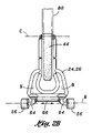
さて、さまざまな表示は本発明の好ましい実施形態を説明するためであって、それを限定するためではない図面を参照すると、図に示されるのは三輪の後部操舵スクータ10である。最も広義において、スクータ10は、スクータ10の操舵を行うための角度のあるヨーイングが可能になるように、一つの前輪44と車体18に旋回可能に取り付けられた一対の後輪56とを備えた車体18から構成されている。図1及び図2に示されるように、車体18は前端部12と後端部14とを備え、前端部12から後端部14に延長した長軸Aを定義している。車体18は、横方向に配向された支持アセンブリ24を含み、その支持アセンブリ24に後輪56が取り付けられる。支持アセンブリ24は、スクータ10の操縦者16すなわち乗員が、スクータ10の操縦のときのように上に立つことのできるフットサポート26を備えている。
Referring now to the drawings, which are for purposes of illustrating the preferred embodiment of the present invention and not to limit it, what is shown is a three-wheel
前輪44は、非旋回可能に(すなわち、操舵できないように)、車体18の前端部12に組み付けられている。図1〜2及び4〜7に示されるように、車体18はさらに好ましくは支持アセンブリ24の前方であって、支持アセンブリ24から上方に延伸された、任意のハンドルアセンブリ32を備えている。一実施形態においては、ハンドルアセンブリ32は、適切な手法(例えば、機械的な締結具、溶接等)によって、支持アセンブリ24に強固に連結されている。しかしながら、支持アセンブリ24及びハンドルアセンブリ32は単一の構造体として形成されてもよい。
The
また、ハンドルアセンブリ32及び支持アセンブリ24は、後にさらに詳しく述べるように、これらの間での相対的な横揺れ運動が許されるように、関節ジョイント30によって相互に連結されてもよい。ハンドルアセンブリ32は、スクータ10に乗っている間の立ち位置において、乗員すなわち操縦者16が安定化されるようにまたは均衡が保たれるように構成されている。具体的には、支持アセンブリ24とハンドルアセンブリ32とは、強固に相互に連結されて、ハンドルアセンブリ32はまた、乗員の引き起こすハンドルアセンブリ32の横方向すなわち側方への運動の結果としてのスクータ10の操舵のための手段を提供する。ハンドルアセンブリ32と支持アセンブリ24とが強固に連結されているため、ハンドルアセンブリ32の横揺れ運動は支持アセンブリ24に伝達される。支持アセンブリ24の横揺れ運動の結果は、後に詳述するように、スクータ10が操舵されることによる後輪56の角度のあるヨーイング運動を引き起こす。
Also, the
図1及び2Bに最適に示されるように、後輪56は、後輪56が互いに横方向配置されるように、支持アセンブリ24の後端部14上に組み付けられる。後輪56の支持アセンブリ24への組み付けは、後軸60の中央位置から外方に延伸する旋回シャフト62を備えた後軸60を備えるトラニオン58によって容易に行われる。図1及び3に示されるように、後輪56は後輪軸Dの周囲を回転し、ニュートラル位置68(すなわち、図1に示される)とヨーイング位置70(図4Aに示される)との間の、長軸Aに対する角度のあるヨーイングに特に適合される。重大なことには、前輪44は車体18に強固に固定されていて(すなわち、非旋回可能に取り付けられていて)、スクータ10の操舵は、後輪56の長軸Aに対する角度のあるヨーイングまたは旋回によって、主として、すなわち単独で実施される。
As best shown in FIGS. 1 and 2B, the
図4Aに示されるように、支持アセンブリ24は長軸Aの周りに横方向に揺れるように構成される。スクータ10の一実施形態においては、支持アセンブリ24の横揺れ運動は、後輪56に、スクータ10の操舵機構を形成する、角度のあるヨーイングを引き起こす。例えば、図4Aに最適に示されるように、操縦者16が、支持アセンブリ24の対向する右側と左側の一方に、非対称に荷重かけることにより、スクータ10の旋回を開始してもよい、そして旋回軸角θでの旋回軸Bの配向により、長軸Aに対する反時計周り方向における後輪56のヨーイングを生じる。具体的に、図4Aは、支持アセンブリ24の右側への体重かけ、すなわち荷重の結果、長軸Aに対する後輪56の反時計回りのヨーイングを示す。
As shown in FIG. 4A, the
図2に簡潔に示されるように、操縦者16は、操縦者の体重のほとんどもしくは全てを右脚で支えて、フットサポート26上に立っている。支持アセンブリ24の右側での非対称的な荷重は、図4Aに示される位置への、後輪56の角度のあるヨーイング運動を引き起こす横揺れ運動を生じさせる。一方、支持アセンブリ24の左側への荷重は、左旋回を開始するための長軸Aに対する後輪56の時計回りのヨーイングを引き起こすという、反対の効果を備える。認識されるように、操縦者16は、スクータ10を、支持アセンブリ24の右側及び左側への非対称の荷重を変更することによって、前方へ走行する間に、方向を制御することができる。非対称の荷重付与は、単に、操縦者の体重を左脚または右脚に変更することによって、容易に行える。
As shown briefly in FIG. 2, the
一実施形態においては、図4Aに示されるように、後輪56が取り付けられるトラニオン58は、約45度を上限とする半角で、長軸Aに対する後軸60へのヨーイング性能を提供するために好ましくは適合されている。しかしながら、トラニオン58が、いずれの角度の角度のあるヨーイング性能を提供するために構成されてもよいことは注意すべきである。図1及び3に示されるように、後輪56は、好ましくは、後軸60の両端に組み付けられている。
In one embodiment, as shown in FIG. 4A, the
好ましい実施形態においては、旋回シャフト62は、支持アセンブリ24の非対称の荷重が、後輪56の角度のあるヨーイングを引き起こすように、非垂直方向かつ非横方向に配向されて配置される。さらに好適には、旋回シャフト62は、好ましくは、旋回軸角θで配向されることにより、支持アセンブリ24の横揺れによって、その側の後輪56が前方に動き、反対側の後輪56は後方に動く。そのような配置は、横揺れ運動の程度に比例して、次第により多くの量で旋回するように傾くことを、操縦者16に許容する。
In a preferred embodiment, the
有利なことに、旋回における傾きのための性能は、操縦者16に、乗員を旋回半径の外側に向かって投げ出す傾向にある遠心力の影響に対抗することを許容する。旋回シャフト62は、好ましくは、乗員が旋回の内側に傾くことを許容する(すなわち、乗員の重心の旋回径の内側への移動を容易にする)ように配向されるが、旋回シャフト62は他の各種の配置で配向されてもよい。例えば、旋回シャフト62は、支持アセンブリ24の一側の非対称な荷重により、反対方向の後輪56の角度のあるヨーイングをもたらすように配向されてもよい。
Advantageously, the performance for tilt in turning allows the
しかしながら、図1、2及び6に最適に示されるように、旋回軸Bのように長軸Aに対して旋回軸角θで傾斜して配置されるような配置であって、旋回軸Bは車体18の後端部14から前端部12に向かう方向に沿って下方に配向される配置が好ましい。具体的には、旋回シャフト62は、上端部及び下端部を備え、旋回シャフト62の下端部は旋回シャフト62の上端部の前方に位置するように傾斜されている。
However, as best shown in FIGS. 1, 2 and 6, the swivel axis B is arranged so as to be inclined at the swivel axis angle θ with respect to the long axis A, and the swivel axis B is An arrangement that is oriented downward along the direction from the
既に述べたように、支持アセンブリ24が左または右への横揺れをするとき、傾斜した旋回シャフト62は、スクータ10の目的の旋回方向と反対方向でのヨーイングにおける後輪56の機械的な操舵を許容する。例えば、操縦者16が、スクータの右旋回を実行することを望む場合、操縦者16は、支持アセンブリ24の右側に非対称に荷重をかけ、支持アセンブリ24の下方への横揺れ(ローリング)を生じさせる。この支持アセンブリ24の下方への横揺れは、後輪56を反対方向に旋回させる。このように、操縦者16は、フットサポート26の不均等な体重かけの作用によって、横揺れを引き起こし、次に、角度のあるヨーイングまたは後輪56の旋回をもたらす。支持アセンブリ24の非対称の荷重の度合いが大きければ大きいほど、角度のあるヨーイングの角度はより大きくなる(すなわち、旋回半径は小さくなる)。
As already mentioned, when the
図に示されるように、ハンドルアセンブリ32は支持アセンブリ24の前方に位置し、ほぼ垂直方向に沿って支持アセンブリ24から上方に延伸する。図6に示される一実施形態において、ハンドルアセンブリ32は、前輪44が取り付けられた一対の下パイプ22またはフォークから上方に延伸する、垂直なアーム部材36を備える。縦方向のアーム部材36は、操縦者16が、スクータ10に乗る間、安定化及び/又はバランスを取るために、掴まれるまたは握られるように構成される。有利なことに、ハンドルアセンブリ32はまた、支持アセンブリ24の横揺れを、そのリジッドな連結によって容易にする。このように、操縦者16は、後輪56のヨーイングをより早い速度で実行するために、支持アセンブリ24の非対称的な荷重と、ハンドルアセンブリ32の横揺れとの組み合わせによって、ハンドルアセンブリ32で操舵を開始することができる。
As shown, the
図6にさらに示されるように、ハンドルアセンブリ32の垂直なアーム部材36は、操縦者16によって握られる握り部38すなわちハンドグリップが人間工学的な形状に適合されてもよい。車体18は、ハンドルアセンブリ32から延伸された弧状のストラト部材28をさらに備えてもよい。スラスト部材28は、好ましくは、前輪44と整列され、その下端部でフットサポート26と接続されている。スラスト部材28は、車体18の、全体構造の剛性、ねじり剛性及び全体の強度を増加させることができる。増加された剛性及び強度は、特定の操縦の実行時、または難しい地形におけるスクータ10の操作を行うときに望ましい。
As further shown in FIG. 6, the
スラスト部材28は、好ましくは、スクータ10の乗車時に操縦者の脚がスラスト部材28にまたがるように構成される。しかしながら、図1及び2に示される配置において、スラスト部材28は全て省略されて、車体18が提供されている。スラスト部材28が省略された実施形態では、支持アセンブリ24及びハンドルアセンブリ32は、好ましくは、車体18に対して十分な強度と剛性とをまとめて提供するように寸法を合わせられている。
The
図1、2及び3に示されるように、スクータ10はさらに、トラニオン58に作動的に連結されるとともに後軸60をニュートラル位置68に向けて偏位するように構成されたバイアス機構またはバイアス部材54を備えてもよい。既に述べたように、後軸60がニュートラル位置68にあるとき、後軸60は車体18の長軸Aに対してほぼ直交するように、配向されている。備えられる場合、バイアス部材54は、図4Aに示されるようなヨーイング位置70から、図1に示されるような非ヨーイングまたはニュートラル位置68への、後輪56の復帰を生じさせることが望ましい。この点で、バイアス部材54は、支持アセンブリ24の横揺れまたは傾斜に対抗し、スクータ10に対して望ましい安定化特性を付与する支持アセンブリ24の非横揺れ位置への復帰を引き起こす。
As shown in FIGS. 1, 2 and 3, the
加えて、バイアス部材54は、好ましくは、後輪56の徐々に増大するヨーイング角において、徐々に高度化する剛性または偏位力を付与するように構成される。バイアス部材54の徐々に増大する剛性はまた、乗せ台の、高速で走行するときに重要な横方向の振動または揺動(すなわち、側面から側面)を防止する。バイアス部材54によって付与されるさらなる利益は、スクータ10が静止または駐車しているときの自立特性であり、それによってハンドルアセンブリ32と前輪44とが垂直配向状態に維持される。総合的に、バイアス部材54は、支持アセンブリ24の横揺れ運動に抵抗することによって、低速だけではなく高速においても、スクータ10に安定性を与える。
In addition, the biasing
バイアス部材54は、後軸60と支持アセンブリ24との間での相対的な移動を抑制するために、支持アセンブリ24とトラニオン58との間で固定されるゴム要素または部材を、これに限定されないが、備える変更配置で構成されてもよい。一方、ばね50またはばねの対は、横揺れ運動に対抗するために、後軸60と支持アセンブリ24との間に挿入されてもよい。ばねダンパ52は、スクータ10のさらなる安定化のため、バイアス部材54中のばね50のレートを減らすために、バイアス部材54にさらに備えられてもよい。
The
その他の実施形態において、図2Bは、一対のほぼ垂直に配向されたスピンドル64によるそれぞれの後輪56の個々の組み付けを示している。それぞれのスピンドル64は、後輪56の旋回についての旋回軸Bを定義する。図2Bに示されるように、対をなす後輪56は、連結機構66すなわち連結棒で、相互に連結されていてもよい。このように、後輪56は、後輪56がそれらの対応する旋回軸Bの周りに、一体にヨーイングするように、互いに機械的に連結されている。
In other embodiments, FIG. 2B shows the individual assembly of each
図2Bはさらに、連結機構66すなわち連結棒によって後輪56を相互に連結するために、それぞれのスピンドル64に固定された制御アームを示す。少なくとも一つのスピンドル64は、後輪56の一つに装着された、操舵アーム(図示しない)を備えることができる。制御アームによって一方の後輪56に付与された旋回運動は、次に、連結機構66によって他方の後輪56に伝達される。
FIG. 2B further shows a control arm secured to each
スクータ10の操舵は、制御アームにおいて旋回運動を引き起こすレバー(図示しない)などの足始動または手始動の操舵機構によって行われて、後輪56へ伝達されてもよい。
The steering of the
図1を一時的に参照すると、スクータ10は、前輪44及び後輪56の少なくとも一方に、作動的に連結されたサスペンションシステム20をさらに備えてもよい。サスペンションシステム20は、好ましくは、水平ではない地形上を走行するとき、あるいは砂利、舗装路の割れ目または歩道の舗装継ぎ目のような小さな障害物に出くわしたときに生じることのあるような、車体18に対する前輪44及び/または後輪56の縦方向への偏位を許容するように適合されている。サスペンションシステム20は、ばね機構のリバウンド率と抑制された振動を制御するためのダンパ52を任意にさらに備える衝撃吸収装置のような一対のばね機構を備えてもよい。
Referring temporarily to FIG. 1, the
図1に示されるように、サスペンションシステム20は、前輪44の両側において、それぞれの下パイプ22に組み入れられた衝撃吸収装置型のアセンブリを含んでもよい。それぞれの衝撃吸収装置は、それぞれの下パイプ22上に位置するフランジ48で終結する。フランジ48は、前輪44が前輪軸Cの周りに回転可能な状態で、前輪44のハブ46を支持する。一方、サスペンションシステム20は、例えば、下パイプ22の真上に位置する垂直なアーム部材36に組入れられたばね50及び/又はダンパ52のユニットのように他の配置で構成されてもよい。さらに検討すると、後輪56は、例えば、後輪56が水平でない地形に出くわしたときのように車体18に対する後輪56の縦方向の偏位を許容するために、支持アセンブリ24とトラニオン58との間に、サスペンションシステム20を備えてもよい。
As shown in FIG. 1, the
図4を参照すると、図示されているのは、旋回操作の実行中だけではなく、ストレート且つ水平の走行の間も、安定化のために、横方向のアーム部材32の少なくとも一つまたは両方を操縦者16が掴むことのできるハンドルアセンブリ32を備えているスクータ10である。それぞれのアーム部材34は、操縦者の手によってしっかりと掴むことを容易にするために、グリップ部38を備えていてもよい。
Referring to FIG. 4, illustrated is not only during a turning operation, but also during straight and horizontal travel, at least one or both of the
ハンドルアセンブリ32は従来のハンドルバーに似たものであるが、強調すべきことは、前輪44が旋回しないように車体18に固定されていて、それゆえ、従来、自転車に存在する操舵能力を備えていないことである。この点に関して、スクータ10の操舵は、体重移動の結果、及び/又はハンドルアセンブリ32の左右の横方向運動の結果として生じる支持アセンブリ24の横揺れに応じた後輪56の角度のあるヨーイングによって、もたらされる。ハンドルアセンブリ32は、好ましくは、立ち位置または座り位置の操縦者16による手頃な把持に適した高さに配置される。高さ調整の機能は、異なる大きさの乗員に適応するためにハンドルアセンブリ32に備えられてもよい。さらに、左右に延伸するアーム部材34は、異なる幅、形状、及び/又は角度配向のハンドルアセンブリの組み付けを許容するために、交換可能な構成として提供されてもよい。
The
図1及び2を一時的に参照すると、スクータ10は、ハンドルアセンブリ32の上方部分から、横方向後方に延伸するパーチポスト74によって支持される座席すなわちパーチ72をさらに備えてもよい。パーチ72は、好ましくは、操縦者16が乗員の膝を僅かに曲げることによってまたぐ、または、乗るために適切な高さでパーチポスト74に組み付けられている。任意に、パーチ72は、身長の異なる操縦者16に適合するために、高さ調整可能に構成されていてもよい。さらに、パーチ72は、好ましくは、ハンドルアセンブリ32に対してほぼ平行にパーチポスト74が折り畳まれるように、ハンドルアセンブリ32に旋回可能に連結されるように適合されている。パーチポスト72が折り畳まれたとき、スクータ10の占める全容積が最小になり、スクータ10の搬送及び保管が容易になる。
1 and 2, the
パーチポスト74の旋回を容易にするために、図2に示されるように、スクータ10は、支持アセンブリ24に組付けられるピンに係合するように構成されてその一端に戻り止めを備えた溝を有する溝付き留め具76をさらに備えてもよい。このように、パーチポスト74の上方旋回は、パーチポスト74が上方へ旋回されるときにピンが溝をスライドするように、戻り止めをピンから最初に離脱させることによって、容易に行われる。
To facilitate pivoting of the
図7を一時的に参照すると、スクータ10のさらなる実施形態において、車体18は、車体18の前方の下端部において支持アセンブリ24とハンドルアセンブリ32との間に介在する関節ジョイント30を備えている。関節ジョイント30は、水平方向に配向された支持アセンブリ24を、垂直方向に配向されたハンドルアセンブリ32に、ねじりを伴って連結するように構成されている。この点に関し、関節ジョイント30は、ハンドルアセンブリ32とは反対方向の、支持アセンブリ24の横揺れ運動を許容するように構成されている。
Referring temporarily to FIG. 7, in a further embodiment of the
関節ジョイント30は、操縦者16が、ハンドルアセンブリ32で位相をずらして、フットサポート26を横揺れさせること(すなわち、非対称的な荷重をかけること)によって、自転車スケートボードを推進させる手段を提供する。それによって推進力が生成され、次いで、スクータ10の前進運動に変換される。関節ジョイント30は、支持アセンブリ24及びハンドルアセンブリ32をニュートラル配列に付勢して、ハンドルアセンブリ32に対する支持アセンブリ24の位相ずれ運動を容易にするために、コイルばね50等のバイアス手段及び/又はダンパ手段をさらに備えてもよい。そのような配置はまた、スクータ10に対する自己操舵特性だけでなく、スクータ10の非使用期間における自立特性を付与する。バイアス手段はさらに、ハンドルアセンブリ32に対する支持アセンブリ24への横揺れ抵抗を付与し、これによって低速でスクータ10を安定化させる。
The joint joint 30 provides a means for the
未だ図7を参照すると、パーチ72は、スクータ10の着座での運転を許容するために、パーチポスト74がフットサポート26から垂直方向上方に延伸するように変更された状態で、支持されてもよい。一対の留め具76は、パーチ72に座った操縦者16の体重の下で、パーチポスト74の荷重支持特性を増加させるために、フットサポート26から上方に延伸してもよい。フットサポート26は、好ましくは、パーチ72に座ったとき、操縦者の足を置くために十分な面積を提供するように構成される。
Still referring to FIG. 7, the
図2を一時的に参照すると、スクータ10は、前輪44及び後輪56の少なくとも一方に駆動可能に連結されたモータ82を任意に備えてもよい。モータ82は、スクータ10の推進のため、前輪44及び/又は後輪56への回転運動を与えるために構成される。モータ82は、電気モータ82として構成されてよく、後軸60に連結されるモーターシャフトによるように、後輪56に作動的に連結されてもよい。モータ82のための動力は、モータ82と接続されたバッテリーのような動力源84によって提供されてもよく、図2に示されるように、フットサポート26の下に取り付けられてもよい。好ましくは、モータ82及び/又は動力源84は、スクータ10の操舵の間、支持アセンブリ24の横揺れ運動に対応するのに十分な地上高を提供するように取り付けられる。
Referring temporarily to FIG. 2, the
モータ82の調整は、図2、4及び5に示されるように、ハンドルアセンブリ32に取り付けられたスロットル40の使用を通じて容易にされ得る。スクータ10のブレーキ又は速度低下は、図2、4及び5に示されるように、対向する左右のアーム部材34の少なくとも一つに取り付けられるブレーキレバー42を介して操作されるディスクブレーキ又はリムブレーキのようなブレーキ機構を通して、容易にされ得る。
Adjustment of the motor 82 may be facilitated through the use of a
図1〜4を参照すると、車体18の一般的な構成は、操縦者16が立てるように、及び後輪56が回転可能に取り付けられるように支持表面を形成する水平に配向された支持アセンブリ24を備える。図3に示す実施形態において、フットサポート26は、乗員の両足を支持するための十分な表面積を提供するように構成される管状部材のような構造的な要素の配置で構成されてもよい。
1-4, the general configuration of the
スクータ10の多様な構成部品の幾何学的な関係に関し、前輪44は、相対的に大径(例えば12インチ(30.5cm)〜28インチ(71.1cm))の空気車輪であって、幅広のタイヤが考えられるが、好ましくは、幅が約2インチ(5.1cm)未満のタイヤ踏み面を備えるものである。タイヤ踏み面自体の断面の形状は、好ましくは、前輪44の横揺れ運動を容易にするために丸みをつけられている。前輪44の直径は、好ましくは、後輪56の直径の約6〜10倍である。後輪56のそれぞれは、好ましくは、後輪56の直径とほぼ等しい幅を備えているが、さまざまな他の幅/直径の比が考えられる。後輪56はまた、好ましくは、旋回の間、横方向のトラクションを最大化するために、ほぼ扁平または平面的な踏み面を備えている。
With respect to the geometrical relationship of the various components of the
既に示されたように、スクータ10の操舵は、操縦者16による支持アセンブリ24の非対称の荷重かけまたは体重かけに応じた後輪56の角度のあるヨーイングによって容易に行われる。フットサポート26上の不均等な荷重かけを行うことによって、前輪44が連結される支持アセンブリ24及びハンドルアセンブリ32の横揺れ運動が、後輪56の角度のあるヨーイングすなわち旋回を引き起こす。車体18または支持アセンブリ24の横揺れ量が多くなるほど、スクータ10の相対的に狭い旋回半径をもたらす後輪56における角度のあるヨーイング動作が大きくなる。
As already indicated, steering of the
後輪56の接触パッチの集合領域は前輪44の接触パッチよりも大きいので、スクータ10の操舵は、角度のあるヨーイングまたは後輪56の長軸Aからの旋回偏位の結果として、主に実現される。後輪56のトラクションは、支持アセンブリ24の横揺れの量に関して後輪56のコンプライアンスの程度を最適化することによって、最大化され得る。このようにして、後輪56は、後輪56のヨーイング角に関わらず、スクータ10の操舵の間、地面との接触を保持することができる。
Since the contact patch collection area of the
スクータ10は、さらに、付加的な付属品又は特徴を備えていてもよい。例えば、図1及び2に示されるように、フェンダー80が操縦者16と前輪44との接触を防ぐために設けられてもよい。図示されるように、フェンダー80は、ハンドルアセンブリ32の下パイプ22に取り付けられ得る。同様に、小さなフェンダー80は、乗員の足との不慮の接触を防ぐために、それぞれの後輪56の上に設けられてもよい。ウイリーバーは、スクータ10の過回転または反転を防ぐために、ウイリーバーが支持アセンブリ24の後部から後方に延伸されることによって、スクータ10に付加的に備えられるようにしてもよい。フットペグは、前輪44の前軸にまたはその下に、付加的に配置されてもよい。同様に、床板、かご、袋、及び/又は補助輪がさらにスクータ10に設けられてもよい。加えて、前方ヘッドライト及び後方ライトのような照明器具は、安全部品として、すなわち、視野の状態が低下している間に運転を可能にするために、スクータ10に設けられてもよい。
The
運転時に、スクータ10は、操縦者の足によるような後方における操縦者16の単純な押しを含む多種の異なるモードによって、前方に推進させられてもよい。既に述べられたように、スクータ10はさらに、支持アセンブリ24の横揺れとともに前輪44の位相のずれた横揺れによって、前方に推進させられてもよい。そのような位相ずれ運動の間に生じたエネルギーは、スクータ10の前方への推進を容易にする。スクータ10の前方への推進は、さらに、電気モータ82の前輪44及び/又は後輪56の少なくとも一つへの回転運動の付与によって、与えられてもよい。図5に示されるように、モータ82の調整は、ハンドルアセンブリ32に取り付けられるスロットル40によって、容易に行われるようにしてもよい。スクータ10の速度低下または停止は、ハンドルアセンブリ32に取り付けられるブレーキレバー42を介して制御されるブレーキ機構によって、容易に行われるようにしてもよい。
When driving, the
以上の説明は、例示であって、限定されるものではない。以上の開示に鑑み、当業者は、ここに開示される発明の範囲及び精神内において多様に変更することができる。さらに、ここに開示された実施形態の多様な特徴は、単独または、それぞれ他のものと変更して組み合わせて使用可能であり、ここに述べたような特別な組み合わせに限定されることを意図するものではない。従って、請求の範囲は図示された実施形態に限定されるものではない。 The above description is illustrative and not limiting. In view of the above disclosure, those skilled in the art can make various changes within the scope and spirit of the invention disclosed herein. Further, various features of the embodiments disclosed herein may be used alone or in combination with each other and are intended to be limited to the specific combinations as described herein. It is not a thing. Accordingly, the claims are not limited to the illustrated embodiment.
Claims (19)
起立した操縦者を支持するとともに、長軸、前部及び後部を有するフットサポートと、
前記フットサポートの前部に旋回しないように取り付けられた一つの前輪であって、その前輪は前記フットサポートを二分し、起立した操縦者が左右の足により前記前輪を跨ぐことを可能にする前記前輪と、
前記前部において前輪の上方に配置され、フットサポート上に起立した操縦者により把持可能なハンドルアセンブリと、
前記後部において同軸上に配置され、ニュートラル位置とヨーイング位置との間で前記長軸に対してヨーイング可能な一対の後輪であって、前記前輪の直径は前記後輪の直径の6倍から10倍の大きさである前記後輪と、
後軸を有するトラニオンとを備え、
前記後軸の両端に前記後輪が装着され、後軸は旋回軸の周りに回転可能であり、前記旋回軸の前側は旋回軸の後側よりも下方に配向され、前記長軸の周りのフットサポートの揺れにより、長軸に対する後軸及び後輪のヨーイングを生じさせ、
前記スクータの操舵は、長軸に対する後輪の角度のあるヨーイングによってもたらされるスクータ。 A three-wheeled scooter
A foot support that supports the standing operator and has a long axis, a front portion, and a rear portion;
One front wheel attached to the front of the foot support so as not to turn , the front wheel bisects the foot support, and allows a standing operator to straddle the front wheel with left and right feet Front wheels ,
A handle assembly disposed above the front wheel at the front and gripped by a pilot standing on a foot support;
Disposed on Oite coaxially to the rear, a rear wheel of the pair capable yawing with respect to the long axis between a neutral position and yawing position, the front wheel diameter is 6 times the diameter of the rear wheel The rear wheel is 10 times larger than
And a belt Lannion to having a rear axle,
The rear wheels are attached to both ends of the rear shaft, the rear shaft is rotatable around the pivot axis, the front side of the pivot shaft is oriented downward from the rear side of the pivot axis, and The swing of the foot support causes yaw of the rear shaft and the rear wheel with respect to the long shaft,
The steering of the front Symbol scooter, scooters provided by yawing with the angle of the rear wheels relative to the longitudinal axis.
前記ハンドルアセンブリは前記フットサポートに連結され、そのハンドルアセンブリの横方向の運動が、後輪のヨーイングを容易にするスクータ。 The scooter according to claim 1, wherein
The handle assembly is connected to the foot support, lateral movement of the handle assembly, easily be absent Kuta yawing of the rear wheels.
前記トラニオンは、前記長軸に対する後軸のヨーイング性能が少なくとも45度の半角であるように構成されるスクータ。 The scooter according to claim 1, wherein
The trunnion is a scooter configured such that the yawing performance of the rear axis with respect to the major axis is a half angle of at least 45 degrees.
前記トラニオンに作動的に連結されて、前記後軸をニュートラル位置に向かって付勢するように構成されるバイアス部材を更に備えるスクータ。 The scooter according to claim 1, wherein
The scooter further comprising a bias member operatively coupled to the trunnion and configured to bias the rear axle toward a neutral position.
前記フットサポートを前記ハンドルアセンブリに対して相互に連結する関節ジョイントをさらに備え、
その関節ジョイントは、ハンドルアセンブリに対するフットサポートの横揺れを許容するように構成されるスクータ。 The scooter according to claim 1 , wherein
Further comprising an articulation joint interconnecting said foot support relative to said handle assembly,
The articulated joint is a scooter configured to allow the foot support to roll relative to the handle assembly.
前部及び後部を有し、かつ、長軸を定義する車体と、
前部に旋回しないように取り付けられた一つの前輪と、
後部に対して同軸上に取り付けられ、ニュートラル位置とヨーイング位置との間で長軸に対してヨーイング可能な一対の後輪と、
前記後輪のそれぞれは、前記支持アセンブリに独立して旋回可能に取り付けられ、
前記後輪のそれぞれは、角度のあるヨーイングが互いに一致するように機械的に連結されたスクータ。 A three-wheeled scooter
A vehicle body having a front portion and a rear portion and defining a long axis;
One front wheel attached so as not to turn to the front,
A pair of rear wheels mounted coaxially to the rear and capable of yawing relative to the major axis between a neutral position and a yawing position;
Each of the rear wheels is pivotally attached independently to the support assembly;
Each of the rear wheels is a scooter mechanically connected so that the yawings having an angle coincide with each other.
一対のスピンドルと連結機構とをさらに備え、
前記スピンドルのそれぞれは、対応する後輪の一つを支持アセンブリに旋回可能に取り付けるために構成され、
前記連結機構は、後輪に機械的に連結されるように構成されるスクータ。 The scooter according to claim 6 ,
A pair of spindles and a coupling mechanism;
Each of the spindles is configured to pivotably attach one of the corresponding rear wheels to the support assembly;
The coupling mechanism is a scooter configured to be mechanically coupled to a rear wheel.
前記前輪の直径は、後輪の直径の6倍から10倍であるスクータ。 The scooter according to claim 6 ,
The diameter of the front wheel is a scooter that is 6 to 10 times the diameter of the rear wheel.
前輪及び後輪のうちの少なくとも一つに駆動可能に連結され、スクータの推進のための回転運動を与えるモータをさらに備えるスクータ。 The scooter according to claim 1, wherein
A scooter further comprising a motor that is drivably coupled to at least one of the front and rear wheels and that provides a rotational motion for propulsion of the scooter.
前輪及び後輪のうちの少なくとも一つに作動的に連結され、フットサポートに対して垂直な偏位を許容するように構成されるサスペンションシステムをさらに備えるスクータ。 The scooter according to claim 1, wherein
A scooter further comprising a suspension system operatively connected to at least one of the front and rear wheels and configured to allow a vertical displacement relative to the foot support .
前記ハンドルアセンブリは操縦者による把持のための垂直なアーム部材を有するスクータ。 The scooter according to claim 1, wherein
The handle assembly is a scooter having a vertical arm member for gripping by an operator.
前記ハンドルアセンブリは、操縦者による把持のための垂直なアーム部材から外方に延伸した一対の対向する横方向のアーム部材をさらに備えるスクータ。 The scooter according to claim 11 ,
The handle assembly further includes a pair of opposing lateral arm members extending outwardly from vertical arm members for gripping by a pilot.
起立した操縦者を支持するとともに、スロットを備え、かつ、長軸を定義し、その長軸の周りで揺動可能なフットサポートと、
前記前部において前記前輪の上方に配置され、操縦者の手によって把持可能なハンドルアセンブリと、
前記フットサポートのスロット内において前部に旋回しないように取り付けられ、起立した操縦者の左右の足で跨ぐことが可能な一つの前輪と、
後部に対して後軸の両端に同軸上に取り付けられ、スクータの操舵のためにニュートラル位置とヨーイング位置との間で長軸に対して、固定された旋回軸の周りにヨーイング可能な一対の後輪と
を備え、前記固定された旋回軸は長軸に対して傾斜し、固定された旋回軸の前側は固定された旋回軸の後側よりも下方に配向されて、前記フットサポートが左側に揺れたときにスクータを左側に操舵し、フットサポートが右側に揺れたときにスクータを右側に操舵するようにしたスクータ。 For a standing operator, a three-wheeled scooter having a front part and a rear part ,
The rewritable supporting upstanding pilot, with a slot, and defining a longitudinal axis, and off Ttosapoto pivotable about its long axis,
A handle assembly disposed above the front wheel at the front and grippable by a driver's hand;
One front wheel that is attached so as not to turn in the front part in the slot of the foot support, and can be straddled with the left and right feet of the standing operator ,
A pair of rears that are coaxially mounted on both ends of the rear shaft relative to the rear and can be yawed around a fixed pivot axis with respect to the long axis between the neutral and yawing positions for steering the scooter The fixed pivot axis is inclined with respect to the long axis, the front side of the fixed pivot axis is oriented downward from the rear side of the fixed pivot axis, and the foot support is on the left side. A scooter that steers the scooter to the left when it swings and steers the scooter to the right when the foot support swings to the right .
前記後軸、及び、その後軸に装着された旋回シャフトを備えたトラニオンをさらに有し、前記旋回シャフトは後軸をフットサポートに対して旋回可能に相互に連結し、旋回シャフトは固定された旋回軸に対して同軸上に配列されるスクータ。 The scooter of claim 13 ,
The rear shaft and a trunnion having a swivel shaft mounted on the rear shaft are further included, the swivel shaft interconnecting the rear shaft with respect to the foot support so that the swivel shaft is fixed. A scooter arranged coaxially with the axis.
前輪はフットサポートよりも高い位置に配置された前輪回転軸を備えるスクータ。 The scooter of claim 13 ,
The front wheel is a scooter having a front wheel rotation shaft arranged at a position higher than the foot support.
前記前輪の直径は、後輪の直径の6倍から10倍であるスクータ。 The scooter of claim 15 ,
The diameter of the front wheel is a scooter that is 6 to 10 times the diameter of the rear wheel.
前記後輪の接触パッチは前記前輪の接触パッチよりも大きいスクータ。 The scooter of claim 13 ,
The rear wheel contact patch is a scooter larger than the front wheel contact patch.
前記固定された旋回軸は長軸の平面内に配置されるスクータ。 The scooter of claim 13 ,
The fixed turning axis is a scooter arranged in a plane of a long axis.
前記ハンドルアセンブリはハンドルバーを備えるスクータ。 The scooter of claim 13 ,
The handle assembly includes a handle bar.
Applications Claiming Priority (3)
| Application Number | Priority Date | Filing Date | Title |
|---|---|---|---|
| US11/713,947 US7540517B2 (en) | 2007-03-05 | 2007-03-05 | Three-wheeled rear-steering scooter |
| US11/713,947 | 2007-03-05 | ||
| PCT/US2008/002924 WO2008109103A2 (en) | 2007-03-05 | 2008-03-05 | Three-wheeled rear-steering scooter |
Publications (3)
| Publication Number | Publication Date |
|---|---|
| JP2010520120A JP2010520120A (en) | 2010-06-10 |
| JP2010520120A5 JP2010520120A5 (en) | 2011-07-14 |
| JP5265581B2 true JP5265581B2 (en) | 2013-08-14 |
Family
ID=39738984
Family Applications (1)
| Application Number | Title | Priority Date | Filing Date |
|---|---|---|---|
| JP2009552721A Expired - Fee Related JP5265581B2 (en) | 2007-03-05 | 2008-03-05 | Rear wheel steering three wheel scooter |
Country Status (12)
| Country | Link |
|---|---|
| US (1) | US7540517B2 (en) |
| EP (1) | EP2117912B1 (en) |
| JP (1) | JP5265581B2 (en) |
| KR (1) | KR101594767B1 (en) |
| CN (1) | CN101808885B (en) |
| AU (1) | AU2008223367B2 (en) |
| BR (1) | BRPI0808514A2 (en) |
| CA (1) | CA2680138C (en) |
| IL (1) | IL200545A (en) |
| MX (1) | MX2009008610A (en) |
| RU (1) | RU2470820C2 (en) |
| WO (1) | WO2008109103A2 (en) |
Families Citing this family (44)
| Publication number | Priority date | Publication date | Assignee | Title |
|---|---|---|---|---|
| US1331420A (en) * | 1917-02-23 | 1920-02-17 | Aluminum Castings Company | Internal-combustion engine |
| US8336894B2 (en) | 2007-03-05 | 2012-12-25 | B.E.W. Squared, Llc | Three-wheeled rear-steering scooter |
| US8827296B2 (en) * | 2007-03-05 | 2014-09-09 | Sbyke Usa Llc | Three-wheeled rear-steering scooter |
| RU2494748C2 (en) * | 2007-04-25 | 2013-10-10 | Акуатек С.Р.Л. | High-stable electrolytic water with reduced width of nuclear magnetic resonance peak at half height |
| ITMI20080070A1 (en) * | 2008-01-18 | 2009-07-19 | Mishael Tzoreff | CONVERTIBLE TOY VEHICLE BETWEEN TWO CONFIGURATIONS OF USE |
| US20090205894A1 (en) * | 2008-02-19 | 2009-08-20 | Eaton Harry E | Leaning vehicle |
| US8020881B2 (en) * | 2008-11-11 | 2011-09-20 | Earl Stump | Mobility assistance apparatus |
| US8152176B2 (en) | 2009-06-25 | 2012-04-10 | Sbyke Usa Llc | Truck assembly |
| GB2475309A (en) * | 2009-11-16 | 2011-05-18 | Agco Sa | Vehicle axle mounting arrangement |
| JP2011156904A (en) * | 2010-01-29 | 2011-08-18 | Aisin Seiki Co Ltd | Folding bicycle |
| US8448954B2 (en) | 2010-12-09 | 2013-05-28 | Sbyke Usa Llc | Skate truck |
| US8602422B2 (en) | 2010-12-09 | 2013-12-10 | Sbyke Usa Llc | Three wheeled scooter with rear skate truck and fixed front wheel |
| DE202011001596U1 (en) * | 2011-01-17 | 2011-04-14 | Micro Mobility Systems Ag | Toddler Roller |
| RU2466899C1 (en) * | 2011-06-21 | 2012-11-20 | Николай Петрович Дядченко | Method for one-wheel vehicle control |
| JP6097694B2 (en) * | 2011-10-06 | 2017-03-15 | ヤマハ発動機株式会社 | Electric vehicle |
| JP6122576B2 (en) | 2011-11-11 | 2017-04-26 | 現代自動車株式会社Hyundai Motor Company | Tricycle rear wheel suspension |
| US8646794B2 (en) * | 2012-06-21 | 2014-02-11 | Craig Mullin | Three-wheeled motorized vehicle |
| GB2515794B (en) | 2013-07-04 | 2015-06-10 | Velofeet Ltd | Improvements Relating to Vehicles |
| US9227687B2 (en) | 2013-09-10 | 2016-01-05 | Urban626, Llc | Foldable electric vehicle |
| JP6107614B2 (en) * | 2013-11-15 | 2017-04-05 | トヨタ自動車株式会社 | vehicle |
| CN203975081U (en) * | 2014-07-11 | 2014-12-03 | 浙江金棒运动器材有限公司 | A kind of multi-function baby stroller |
| USD736861S1 (en) | 2014-12-01 | 2015-08-18 | Radio Flyer Inc. | Scooter |
| USD756465S1 (en) | 2015-03-06 | 2016-05-17 | Radio Flyer Inc. | Scooter |
| CA2888318A1 (en) | 2015-04-17 | 2016-10-17 | Jeremie Lepage | Compact scooter |
| USD774979S1 (en) | 2015-05-28 | 2016-12-27 | Urban626, Llc | Motorized scooter |
| US9873476B2 (en) | 2015-05-29 | 2018-01-23 | Urban626, Llc | Foldable electric vehicle |
| US9873477B2 (en) * | 2016-02-18 | 2018-01-23 | Matthias Wunderlin | Collapsible scooter |
| EP3487753A1 (en) | 2016-07-20 | 2019-05-29 | Urban626, LLC | Convertible scooter |
| US10363829B2 (en) | 2016-09-21 | 2019-07-30 | Urban626, Llc | Portable and convertible rechargeable battery power supply |
| CZ2016585A3 (en) * | 2016-09-21 | 2018-06-06 | Radek Mareš | A riding means |
| USD832150S1 (en) | 2016-12-29 | 2018-10-30 | Urban626, Llc | Motorized scooter |
| CN106741406B (en) * | 2016-12-29 | 2022-10-04 | 浙江骑客机器人科技有限公司 | Somatosensory longitudinal two-wheel vehicle |
| CN107128415B (en) * | 2017-05-27 | 2023-02-03 | 浙江哈鹰智能科技有限公司 | Double rear wheel linkage scooter |
| WO2019032545A1 (en) | 2017-08-07 | 2019-02-14 | Urban626, Llc | Compactible scooter with tensioned body |
| USD842169S1 (en) | 2017-08-21 | 2019-03-05 | Urban626, Llc | Electric convenience vehicle |
| IT201800004264A1 (en) * | 2018-04-06 | 2019-10-06 | INNOVATIVE MEANS OF PEDAL TRANSPORT | |
| US20190315425A1 (en) | 2018-04-12 | 2019-10-17 | Nicolas Andrew Bartolotta | Motor driven vehicle |
| US11505237B2 (en) * | 2018-04-12 | 2022-11-22 | Goodbaby Child Products Co., Ltd. | Child swing steering vehicle |
| ES2737728B2 (en) * | 2018-07-05 | 2021-02-25 | Genius Emobility Systems Sl | PROPULSION SYSTEM FOR TROLLEYS BY MEANS OF HOVERBOARD TYPE ELECTRIC SKATEBOARD COUPLED THROUGH AN ARTICULATED STRUCTURE |
| USD865874S1 (en) | 2018-08-21 | 2019-11-05 | Rodski Sports Co. | Vehicle frame |
| US11383787B2 (en) * | 2018-09-26 | 2022-07-12 | GM Global Technology Operations LLC | Multi-axis pivoting coupler joints and drivetrain architectures for intelligent electric scooters |
| RU193880U1 (en) * | 2019-06-13 | 2019-11-19 | Федеральное государственное бюджетное образовательное учреждение высшего образования "Московский автомобильно-дорожный государственный технический университет (МАДИ)" | COMPACT SUSTAINABLE SCOOTER |
| RU193881U1 (en) * | 2019-07-02 | 2019-11-19 | Федеральное государственное бюджетное образовательное учреждение высшего образования "Московский автомобильно-дорожный государственный технический университет (МАДИ)" | Four Wheel Scooter |
| ES2865390A1 (en) * | 2020-04-14 | 2021-10-15 | Rodriguez Antonio Cosmen | Steerable inline roller skate with brakes (Machine-translation by Google Translate, not legally binding) |
Family Cites Families (55)
| Publication number | Priority date | Publication date | Assignee | Title |
|---|---|---|---|---|
| US638963A (en) * | 1897-01-28 | 1899-12-12 | Hermann Ganswindt | Driving mechanism for unicycles. |
| US1607972A (en) * | 1925-09-28 | 1926-11-23 | Wagner Mangold | Propulsion mechanism |
| US1599223A (en) * | 1926-02-16 | 1926-09-07 | Claude A Epps | Tot bike |
| US2198857A (en) * | 1937-09-30 | 1940-04-30 | Alan R Branson | Roller skating device |
| US3284096A (en) * | 1966-05-20 | 1966-11-08 | Wham O Mfg Co | Bicycle accessory |
| US3652101A (en) * | 1969-12-17 | 1972-03-28 | William J Pivonka | Vehicle stabilization apparatus |
| US3860264A (en) * | 1973-01-15 | 1975-01-14 | Mattel Inc | Lean velocipede |
| US3891225A (en) * | 1974-04-22 | 1975-06-24 | Raymond V Sessa | Wheeled ski skate |
| US4103921A (en) * | 1977-06-29 | 1978-08-01 | Carolina Enterprises, Inc. | Rear steering toy wheeled vehicle |
| US4198072A (en) * | 1978-09-01 | 1980-04-15 | Mark Cantrell | Wheeled vehicle |
| US4359231A (en) * | 1980-06-23 | 1982-11-16 | Mulcahy Kevin M | Steering mechanism for three-wheeled vehicles |
| US4469343A (en) * | 1982-12-23 | 1984-09-04 | Weatherford Hugh A | Occupant propelled multi-speed three-wheel vehicle |
| JPS6112480A (en) * | 1984-06-26 | 1986-01-20 | スズキ株式会社 | Steering mechanism of rear wheel for tricycle |
| AU96165S (en) * | 1985-04-16 | 1987-04-09 | Sharp Kk | A sorter |
| USD295728S (en) * | 1985-06-17 | 1988-05-17 | Berry Loren E | Electronic visual metronome |
| USD289985S (en) * | 1985-07-02 | 1987-05-26 | Davenport James M | Recreational cycle |
| US4657272A (en) * | 1985-09-11 | 1987-04-14 | Davenport James M | Wheeled vehicle |
| US4624469A (en) * | 1985-12-19 | 1986-11-25 | Bourne Jr Maurice W | Three-wheeled vehicle with controlled wheel and body lean |
| USD295989S (en) * | 1987-02-13 | 1988-05-31 | Cummings Darold B | Scooter frame |
| USD295428S (en) | 1987-04-13 | 1988-04-26 | Cummings Darold B | Scooter |
| AU610642B2 (en) * | 1987-09-10 | 1991-05-23 | David Allan Parr | A ride-on device for transportation and stunt riding |
| USD300756S (en) * | 1987-11-19 | 1989-04-18 | Cummings Darold B | Scooter |
| US4863182A (en) * | 1988-07-21 | 1989-09-05 | Chern Jiuun F | Skate bike |
| GB8825461D0 (en) * | 1988-10-31 | 1988-11-30 | Allen T A | Anti-inertia & steering device |
| JPH04208623A (en) * | 1990-11-30 | 1992-07-30 | Minoru Kakizoe | Automotive x-shaped torsion bar spring suspension |
| US5127488A (en) * | 1991-06-27 | 1992-07-07 | Tom Shanahan, Inc. | Power accessory for skateboard |
| SU1834672A3 (en) * | 1991-07-15 | 1993-08-15 | Ilyas M Agishev | Skateboard |
| JP2523432B2 (en) * | 1993-03-01 | 1996-08-07 | 均 高橋 | Rollaski |
| US5620189A (en) * | 1993-08-12 | 1997-04-15 | Hinderhofer; Juergen | Scooter |
| DE9312041U1 (en) * | 1993-08-12 | 1993-10-28 | Hinderhofer Juergen | City scooter |
| DE4424297A1 (en) * | 1994-07-09 | 1996-01-11 | Udo Schatz | skateboard of roller board and pneumatic wheels |
| US6739606B2 (en) * | 1996-01-29 | 2004-05-25 | Marky Sparky, Inc. | Dual-footboard scooter |
| JPH10211313A (en) * | 1997-01-28 | 1998-08-11 | New Technol Kenkyusho:Kk | Steering device for self-running type roller board |
| US5853182A (en) * | 1997-02-12 | 1998-12-29 | Finkle; Louis J. | Truck assembly for skateboards |
| US6250656B1 (en) * | 1999-06-01 | 2001-06-26 | Jorge L. Ibarra | Skateboard-bicycle combination |
| US6220612B1 (en) * | 1999-11-05 | 2001-04-24 | J. Gildo Beleski, Jr. | Cambering vehicle and mechanism |
| AUPQ470399A0 (en) * | 1999-12-16 | 2000-01-20 | Reginato, Robert | Scooter assembly |
| US6595536B1 (en) * | 1999-12-29 | 2003-07-22 | Timothy R. Tucker | Collapsible vehicle |
| USD444184S1 (en) * | 2000-02-01 | 2001-06-26 | Heinz Kettler Gmbh & Co. | Scooter |
| CN2428169Y (en) * | 2000-06-02 | 2001-05-02 | 王国梁 | Skeleton correcting structure of scooter |
| US6572130B2 (en) * | 2000-07-24 | 2003-06-03 | H. Peter Greene, Jr. | Three-wheeled vehicle |
| TW497579U (en) * | 2000-11-04 | 2002-08-01 | Melton Internat L L C | Tricycle |
| CN2471690Y (en) * | 2001-03-23 | 2002-01-16 | 信隆实业(深圳)有限公司 | Hand drived scooter |
| JP3080827U (en) * | 2001-04-04 | 2001-10-12 | 榮添 李 | Cycling machine |
| CN2501789Y (en) * | 2001-11-08 | 2002-07-24 | 刘奥宇 | Motor-driven scooter |
| DE10230880A1 (en) * | 2002-06-07 | 2003-12-24 | Chi Fa Intellectual Economy In | Exercise machine with internal tangential drive |
| US7192038B2 (en) * | 2002-08-13 | 2007-03-20 | Sheue-Ing Tsai | Foot propelled scooter |
| GB2394453B (en) * | 2002-10-23 | 2006-03-01 | Kettler Heinz Gmbh | Tricycle |
| JP4411867B2 (en) * | 2003-06-04 | 2010-02-10 | トヨタ自動車株式会社 | Vehicles that can be steered by moving the center of gravity |
| US6942235B2 (en) * | 2003-12-01 | 2005-09-13 | Wen-Pin Chang | Foldable bicycle |
| US20050139406A1 (en) * | 2003-12-31 | 2005-06-30 | Mcleese Eddie S. | Front wheel powered skate board with accessory engagable frame and suspension system |
| EP1740444B1 (en) * | 2004-04-19 | 2010-05-19 | M W Innovators Limited | Foot-propelled wheeled hobby and/or sport device |
| JP2006068087A (en) * | 2004-08-31 | 2006-03-16 | Kaneko Seisakusho:Kk | Auxiliary vehicle for traveling |
| US7290628B2 (en) * | 2004-09-02 | 2007-11-06 | American Chariot Company | Personal transport vehicle system and method |
| JP2006151032A (en) * | 2004-11-25 | 2006-06-15 | Yamaha Motor Co Ltd | Standing ride type small vehicle |
-
2007
- 2007-03-05 US US11/713,947 patent/US7540517B2/en not_active Expired - Fee Related
-
2008
- 2008-03-05 EP EP08726458.6A patent/EP2117912B1/en not_active Not-in-force
- 2008-03-05 KR KR1020097020771A patent/KR101594767B1/en not_active IP Right Cessation
- 2008-03-05 CN CN2008800071300A patent/CN101808885B/en not_active Expired - Fee Related
- 2008-03-05 WO PCT/US2008/002924 patent/WO2008109103A2/en active Application Filing
- 2008-03-05 MX MX2009008610A patent/MX2009008610A/en active IP Right Grant
- 2008-03-05 BR BRPI0808514-5A2A patent/BRPI0808514A2/en not_active Application Discontinuation
- 2008-03-05 JP JP2009552721A patent/JP5265581B2/en not_active Expired - Fee Related
- 2008-03-05 CA CA2680138A patent/CA2680138C/en not_active Expired - Fee Related
- 2008-03-05 RU RU2009136600/11A patent/RU2470820C2/en not_active IP Right Cessation
- 2008-03-05 AU AU2008223367A patent/AU2008223367B2/en not_active Ceased
-
2009
- 2009-08-23 IL IL200545A patent/IL200545A/en active IP Right Grant
Also Published As
| Publication number | Publication date |
|---|---|
| US20080217085A1 (en) | 2008-09-11 |
| RU2470820C2 (en) | 2012-12-27 |
| IL200545A (en) | 2013-06-27 |
| KR20090130020A (en) | 2009-12-17 |
| CA2680138C (en) | 2015-12-01 |
| EP2117912B1 (en) | 2013-04-10 |
| EP2117912A4 (en) | 2010-09-01 |
| AU2008223367B2 (en) | 2013-11-14 |
| WO2008109103A2 (en) | 2008-09-12 |
| RU2009136600A (en) | 2011-04-20 |
| CA2680138A1 (en) | 2008-09-12 |
| CN101808885B (en) | 2013-05-22 |
| AU2008223367A1 (en) | 2008-09-12 |
| WO2008109103A3 (en) | 2009-12-30 |
| US7540517B2 (en) | 2009-06-02 |
| BRPI0808514A2 (en) | 2014-11-04 |
| JP2010520120A (en) | 2010-06-10 |
| IL200545A0 (en) | 2010-05-17 |
| KR101594767B1 (en) | 2016-02-17 |
| CN101808885A (en) | 2010-08-18 |
| EP2117912A2 (en) | 2009-11-18 |
| MX2009008610A (en) | 2010-01-25 |
Similar Documents
| Publication | Publication Date | Title |
|---|---|---|
| JP5265581B2 (en) | Rear wheel steering three wheel scooter | |
| US10300976B2 (en) | Three-wheeled rear-steering scooter | |
| ES2806750T3 (en) | Three wheel incline bike | |
| US7708291B1 (en) | Vehicle with improved steering system | |
| US10131397B2 (en) | Vehicle stability, steering, ride characteristics and control | |
| USRE44854E1 (en) | Vehicle with improved integrated steering and suspension system | |
| JP2008502536A (en) | Ski sledge | |
| US8827296B2 (en) | Three-wheeled rear-steering scooter | |
| US8973695B2 (en) | Vehicle wheeled device | |
| KR101010117B1 (en) | The bicycle with rear wheel steering | |
| JP2020032991A (en) | Motor-driven skateboard | |
| US20190351314A1 (en) | Lean-steered mountain board and method of operation | |
| CN108883808B (en) | Two-wheeled vehicle | |
| JP6832692B2 (en) | Rough terrain vehicle | |
| JP7001291B1 (en) | Front wheel suspension mechanism and three-wheeled vehicle | |
| JP6837450B2 (en) | Rough terrain vehicle |
Legal Events
| Date | Code | Title | Description |
|---|---|---|---|
| A621 | Written request for application examination |
Free format text: JAPANESE INTERMEDIATE CODE: A621 Effective date: 20110303 |
|
| A521 | Request for written amendment filed |
Free format text: JAPANESE INTERMEDIATE CODE: A523 Effective date: 20110411 |
|
| RD04 | Notification of resignation of power of attorney |
Free format text: JAPANESE INTERMEDIATE CODE: A7424 Effective date: 20120112 |
|
| A131 | Notification of reasons for refusal |
Free format text: JAPANESE INTERMEDIATE CODE: A131 Effective date: 20120710 |
|
| A977 | Report on retrieval |
Free format text: JAPANESE INTERMEDIATE CODE: A971007 Effective date: 20120712 |
|
| A601 | Written request for extension of time |
Free format text: JAPANESE INTERMEDIATE CODE: A601 Effective date: 20120926 |
|
| A602 | Written permission of extension of time |
Free format text: JAPANESE INTERMEDIATE CODE: A602 Effective date: 20121003 |
|
| A521 | Request for written amendment filed |
Free format text: JAPANESE INTERMEDIATE CODE: A523 Effective date: 20121214 |
|
| TRDD | Decision of grant or rejection written | ||
| A01 | Written decision to grant a patent or to grant a registration (utility model) |
Free format text: JAPANESE INTERMEDIATE CODE: A01 Effective date: 20130409 |
|
| A61 | First payment of annual fees (during grant procedure) |
Free format text: JAPANESE INTERMEDIATE CODE: A61 Effective date: 20130501 |
|
| R150 | Certificate of patent or registration of utility model |
Ref document number: 5265581 Country of ref document: JP Free format text: JAPANESE INTERMEDIATE CODE: R150 Free format text: JAPANESE INTERMEDIATE CODE: R150 |
|
| R250 | Receipt of annual fees |
Free format text: JAPANESE INTERMEDIATE CODE: R250 |
|
| LAPS | Cancellation because of no payment of annual fees |