JP5265559B2 - Inter-cell power control in the presence of partial frequency reuse - Google Patents
Inter-cell power control in the presence of partial frequency reuse Download PDFInfo
- Publication number
- JP5265559B2 JP5265559B2 JP2009535419A JP2009535419A JP5265559B2 JP 5265559 B2 JP5265559 B2 JP 5265559B2 JP 2009535419 A JP2009535419 A JP 2009535419A JP 2009535419 A JP2009535419 A JP 2009535419A JP 5265559 B2 JP5265559 B2 JP 5265559B2
- Authority
- JP
- Japan
- Prior art keywords
- interference
- load indicator
- average
- sector
- frequency
- Prior art date
- Legal status (The legal status is an assumption and is not a legal conclusion. Google has not performed a legal analysis and makes no representation as to the accuracy of the status listed.)
- Expired - Fee Related
Links
Images


Classifications
-
- H—ELECTRICITY
- H04—ELECTRIC COMMUNICATION TECHNIQUE
- H04W—WIRELESS COMMUNICATION NETWORKS
- H04W52/00—Power management, e.g. TPC [Transmission Power Control], power saving or power classes
- H04W52/04—TPC
- H04W52/18—TPC being performed according to specific parameters
- H04W52/24—TPC being performed according to specific parameters using SIR [Signal to Interference Ratio] or other wireless path parameters
- H04W52/241—TPC being performed according to specific parameters using SIR [Signal to Interference Ratio] or other wireless path parameters taking into account channel quality metrics, e.g. SIR, SNR, CIR, Eb/lo
-
- H—ELECTRICITY
- H04—ELECTRIC COMMUNICATION TECHNIQUE
- H04W—WIRELESS COMMUNICATION NETWORKS
- H04W52/00—Power management, e.g. TPC [Transmission Power Control], power saving or power classes
- H04W52/04—TPC
- H04W52/18—TPC being performed according to specific parameters
- H04W52/24—TPC being performed according to specific parameters using SIR [Signal to Interference Ratio] or other wireless path parameters
-
- H—ELECTRICITY
- H04—ELECTRIC COMMUNICATION TECHNIQUE
- H04W—WIRELESS COMMUNICATION NETWORKS
- H04W16/00—Network planning, e.g. coverage or traffic planning tools; Network deployment, e.g. resource partitioning or cells structures
- H04W16/02—Resource partitioning among network components, e.g. reuse partitioning
- H04W16/12—Fixed resource partitioning
-
- H—ELECTRICITY
- H04—ELECTRIC COMMUNICATION TECHNIQUE
- H04W—WIRELESS COMMUNICATION NETWORKS
- H04W24/00—Supervisory, monitoring or testing arrangements
- H04W24/02—Arrangements for optimising operational condition
-
- H—ELECTRICITY
- H04—ELECTRIC COMMUNICATION TECHNIQUE
- H04W—WIRELESS COMMUNICATION NETWORKS
- H04W52/00—Power management, e.g. TPC [Transmission Power Control], power saving or power classes
- H04W52/04—TPC
- H04W52/18—TPC being performed according to specific parameters
- H04W52/24—TPC being performed according to specific parameters using SIR [Signal to Interference Ratio] or other wireless path parameters
- H04W52/247—TPC being performed according to specific parameters using SIR [Signal to Interference Ratio] or other wireless path parameters where the output power of a terminal is based on a path parameter sent by another terminal
-
- H—ELECTRICITY
- H04—ELECTRIC COMMUNICATION TECHNIQUE
- H04W—WIRELESS COMMUNICATION NETWORKS
- H04W52/00—Power management, e.g. TPC [Transmission Power Control], power saving or power classes
- H04W52/04—TPC
- H04W52/06—TPC algorithms
- H04W52/14—Separate analysis of uplink or downlink
- H04W52/146—Uplink power control
-
- H—ELECTRICITY
- H04—ELECTRIC COMMUNICATION TECHNIQUE
- H04W—WIRELESS COMMUNICATION NETWORKS
- H04W52/00—Power management, e.g. TPC [Transmission Power Control], power saving or power classes
- H04W52/04—TPC
- H04W52/18—TPC being performed according to specific parameters
- H04W52/22—TPC being performed according to specific parameters taking into account previous information or commands
- H04W52/225—Calculation of statistics, e.g. average, variance
-
- H—ELECTRICITY
- H04—ELECTRIC COMMUNICATION TECHNIQUE
- H04W—WIRELESS COMMUNICATION NETWORKS
- H04W52/00—Power management, e.g. TPC [Transmission Power Control], power saving or power classes
- H04W52/04—TPC
- H04W52/30—TPC using constraints in the total amount of available transmission power
- H04W52/34—TPC management, i.e. sharing limited amount of power among users or channels or data types, e.g. cell loading
- H04W52/343—TPC management, i.e. sharing limited amount of power among users or channels or data types, e.g. cell loading taking into account loading or congestion level
Description
下記の記載は、一般に無線通信に係わり、そして特に、無線通信システムにおけるセル間出力制御に関する。 The following description relates generally to wireless communication, and more particularly to inter-cell power control in a wireless communication system.
[米国特許法35§119による優先権の主張]
本出願は、米国特許仮出願番号第60/863,792号、2006年10月31日出願、名称“FFRによるセル間出力制御(INTER-CELL POWER CONTROL WITH FFR)”、に優先権を主張する。この出願の全体は、引用によって本明細書中に取り込まれている。
[Claim of priority under 35 USC § 119]
This application claims priority to US Provisional Patent Application No. 60 / 863,792, filed Oct. 31, 2006, entitled “INTER-CELL POWER CONTROL WITH FFR”. . The entirety of this application is incorporated herein by reference.
移動体通信ネットワーク(例えば、セルラ電話ネットワーク)内で情報を送信するために利用する従来技術は、周波数分割に基づく技術、時分割に基づく技術、及びコード分割に基づく技術を含む。一般に周波数分割に基づく技術を用いると、通話(call)は、周波数接続方法に基づいて分割される、そこでは、個々の通話は、別々の周波数に配置される。時分割に基づく技術を用いると、個々の通話は、指定された周波数において時間のある部分を割り当てられる。コード分割に基づく技術を用いると、個々の通話は、固有のコードに関係付けられ、そして利用可能な周波数全体にわたり拡散される。それぞれの技術は、1又はそれより多くのユーザによる多元接続に対応することが可能である。 Prior art techniques utilized to transmit information within a mobile communications network (eg, a cellular telephone network) include frequency division based techniques, time division based techniques, and code division based techniques. In general, using techniques based on frequency division, calls are divided based on the frequency connection method, where individual calls are placed on separate frequencies. Using time division based techniques, individual calls are assigned a portion of time at a specified frequency. With code division based techniques, individual calls are associated with unique codes and spread across the available frequencies. Each technology can accommodate multiple access by one or more users.
より具体的に、周波数分割に基づく技術は、一般に、スペクトルを帯域幅の一様なチャンク(chunk:塊)へと分割することにより別個のチャネルへとスペクトルを分離する、例えば、無線セルラ電話通信のために割り当てられる周波数帯域の分割は、30チャネルへと分割されることが可能であり、そのそれぞれは音声の会話を搬送することができる、又はディジタル・サービスを用いて、ディジタル・データを搬送することができる。各チャネルは、同時に1つのユーザだけに割り当てられることが可能である。1つの通常利用される変形は、直交周波数分割技術であり、それは全体のシステム帯域幅を複数の直交副帯域へと効率的に区分する。これらの副帯域は、しかも、トーン、キャリア、サブキャリア、ビン、及び周波数チャネル、とも呼ばれる。各副帯域は、サブキャリアと関係付けられ、それはデータとともに変調されることができる。時分割に基づく技術を用いると、帯域は、連続する時間スライス又は時間スロットへと時間方式で分割される。チャネルの各ユーザは、巡回(round-robin)方式で情報を送信し受信するための時間スライスを与えられる。例えば、任意の所与の時間tにおいて、ユーザは、短いバースト(burst)のあいだチャネルへのアクセスを与えられる。次に、アクセスは、情報を送信し受信するために時間の短いバーストを与えられている別のユーザに切り替えられる。“交替”の循環は継続し、そして最終的に各ユーザは、複数の送信及び受信バーストを与えられる。 More specifically, frequency division based techniques generally separate the spectrum into separate channels by dividing the spectrum into bandwidth uniform chunks, eg, wireless cellular telephony The division of the frequency band allocated for can be divided into 30 channels, each of which can carry voice conversations, or use digital services to carry digital data can do. Each channel can be assigned to only one user at a time. One commonly used variant is the orthogonal frequency division technique, which effectively partitions the overall system bandwidth into multiple orthogonal subbands. These subbands are also called tones, carriers, subcarriers, bins, and frequency channels. Each subband is associated with a subcarrier, which can be modulated with data. With time division based techniques, the bandwidth is divided in time manner into successive time slices or time slots. Each user of the channel is given a time slice to send and receive information in a round-robin manner. For example, at any given time t, a user is given access to the channel for a short burst. The access is then switched to another user who is given a short burst of time to send and receive information. The “alternating” cycle continues and eventually each user is given multiple transmission and reception bursts.
コード分割に基づく技術は、典型的には、範囲内の任意の時間において利用可能な複数の周波数を介してデータを送信する。一般に、データは、ディジタル化されそして利用可能な帯域幅にわたり拡散される、ここで、複数のユーザがチャネル上で重ねられることが可能であり、そして個々のユーザは、固有の系列コードを割り当てられることができる。ユーザは、スペクトルの同じ広帯域チャンクにおいて送信することが可能である、そこでは、各ユーザの信号は、自身の個々の固有の系列コードにより全体の帯域幅にわたり拡散される。この技術は、共有することを提供することができ、そこでは、1又はそれより多くのユーザが同時に送信しそして受信することが可能である。そのような共有することは、スペクトル拡散ディジタル変調を通して実現されることが可能であり、そこでは、ユーザのビットのストリームは、エンコードされ、そして擬似−ランダム様式で非常に広いチャネル全体にわたり拡散される。受信機は、関係付けられた固有の系列コードを認識するように、そしてコヒーレントな方式で特定のユーザに関するビットを集めるためにランダム化を元に戻すように設計される。 Code division based techniques typically transmit data over multiple frequencies available at any time within range. In general, the data is digitized and spread over the available bandwidth, where multiple users can be overlaid on the channel and each user is assigned a unique sequence code be able to. Users can transmit in the same wide-band chunk of spectrum, where each user's signal is spread over the entire bandwidth by its own unique sequence code. This technique can provide sharing, where one or more users can transmit and receive simultaneously. Such sharing can be achieved through spread spectrum digital modulation, where the user's stream of bits is encoded and spread across a very wide channel in a pseudo-random fashion. . The receiver is designed to recognize the associated unique sequence code and undo the randomization to collect bits for a particular user in a coherent manner.
(例えば、周波数分割技術、時分割技術及びコード分割技術を利用する)一般的な無線通信ネットワークは、通信可能領域を提供する1又はそれより多くの基地局と、その通信可能領域内でデータを送信しそして受信することが可能である1又はそれより多くの移動端末(例えば、無線端末)を含む。典型的な基地局は、ブロードキャスト・サービス、マルチキャスト・サービス、及び/又はユニキャスト・サービスのために複数のデータ・ストリームを同時に送信することが可能であり、そこでは、データ・ストリームは、移動端末にとって関心のある独立の受信であり得るデータのストリームである。該基地局の通信可能領域内の移動端末は、複合ストリームによって搬送される1つの、又は1つより多くの、又は全てのデータ・ストリームを受信することに関心があり得る。同様に、移動端末は、基地局へ又は別の移動端末へデータを送信することが可能である。基地局と移動端末との間の、又は複数の移動端末間のそのような通信は、チャネル変動及び/又は干渉強度(power)変動のために劣化することがある。例えば、上記の変動は、1又はそれより多くの移動端末に関する基地局スケジューリング、出力(power)制御、及び/又はレート予測に悪影響を及ぼすことがある。 A typical wireless communication network (e.g., using frequency division technology, time division technology and code division technology) has one or more base stations that provide a communicable area and data within that communicable area. Includes one or more mobile terminals (eg, wireless terminals) that are capable of transmitting and receiving. A typical base station can transmit multiple data streams simultaneously for broadcast, multicast, and / or unicast services, where the data streams are transmitted to a mobile terminal A stream of data that may be an independent reception of interest to the user. Mobile terminals within the coverage area of the base station may be interested in receiving one, more than one, or all data streams carried by the composite stream. Similarly, a mobile terminal can transmit data to the base station or to another mobile terminal. Such communication between a base station and a mobile terminal or between multiple mobile terminals may be degraded due to channel variations and / or interference power variations. For example, the above variations may adversely affect base station scheduling, power control, and / or rate prediction for one or more mobile terminals.
上に記述した通信は、有限の帯域幅を前提とし、それは、様々なアプローチの利用を手助けして、許容可能な干渉のレベルを維持しつつ複数の端末にサービスを拡張する。そのようなアプローチのうちの1つは、1よりはるかに小さな再利用による周波数再利用であり、そこでは、多数の隣接するセルは、通信のために本質的に異なる周波数帯域を利用する。しかしながら、システム帯域幅のより良い利用のために、そして例えば、パケット・データ・レート及び能力の増加のために、部分周波数再利用(FFR:fractional frequency reuse)が利用されてきている、ここで、周波数帯域の集合は、本質的に異なる隣接するセル/セクタの動作のために割り当てられることが可能である。それゆえ、通信を改善するために、セル間干渉を緩和し、そしてFFRの存在におけるセル間出力制御を実現する必要性がある。 The communication described above assumes a finite bandwidth, which facilitates the use of various approaches and extends service to multiple terminals while maintaining an acceptable level of interference. One such approach is frequency reuse with reuse much less than one, where a number of adjacent cells utilize essentially different frequency bands for communication. However, fractional frequency reuse (FFR) has been utilized for better utilization of system bandwidth, and for example, for increased packet data rate and capacity, where: A set of frequency bands can be allocated for operation of essentially different adjacent cells / sectors. Therefore, to improve communication, there is a need to mitigate inter-cell interference and implement inter-cell power control in the presence of FFR.
下記は、開示された実施形態の複数の態様の基本的な理解を提供するために、単純化したサマリーを提示する。本サマリーは、広範囲にわたる概観ではなく、そして鍵又は決定的な要素を識別するように意図されていないし、そのような実施形態のスコープの輪郭を叙述するようも意図されていない。その目的は、下記に提示されるより詳細な説明への導入として、説明される実施形態の複数の概念を単純化した形式で提示することである。 The following presents a simplified summary in order to provide a basic understanding of aspects of the disclosed embodiments. This summary is not an extensive overview and is not intended to identify key or critical elements nor is it intended to delineate the scope of such embodiments. Its purpose is to present some concepts of the described embodiments in a simplified form as a prelude to the more detailed description that is presented later.
1つの態様では、無線通信システムにおいて負荷インディケータ(load indicator)を生成するための方法が開示され、前記方法は:無線通信セクタにおいて発せられる干渉に関係付けられる干渉測定規準をモニタすること、前記干渉測定規準がしきい値を超えるかどうかにしたがって負荷インディケータを決定すること、及び前記負荷インディケータを伝達すること、を具備する。 In one aspect, a method for generating a load indicator in a wireless communication system is disclosed, the method comprising: monitoring an interference metric associated with interference emitted in a wireless communication sector, the interference Determining a load indicator according to whether the metric exceeds a threshold and communicating the load indicator.
別の1つの態様では、主題の明細書は、無線通信システムにおいて動作する装置を開示し、前記装置は:無線通信セクタにおいて発せられる干渉に関係付けられる干渉測定規準を決定するための手段、時間−周波数リソースにおける干渉測定規準に関係付けられる負荷インディケータを生成するための手段、負荷インディケータの集合を受信するための手段、及びパワー密度割り当てをスケジューリングするための手段、を具備する。 In another aspect, the subject specification discloses an apparatus operating in a wireless communication system, the apparatus comprising: means for determining an interference metric associated with interference emitted in a wireless communication sector, time -Means for generating a load indicator associated with an interference metric in frequency resources, means for receiving a set of load indicators, and means for scheduling power density assignments.
その上別の1つの態様では、無線通信デバイスが開示され、前記デバイスは:セクタの集合において発せられる干渉をモニタし、モニタした干渉に関係付けられる干渉測定規準がしきい値を超えるとき負荷インディケータをブロードキャストし、バックホール(backhaul)ネットワーク通信を経由して負荷インディケータを伝達し、そして受信した負荷インディケータの論理状態に少なくとも一部は基づいて送信出力を割り当てるように構成された少なくとも1つのプロセッサ、及び前記少なくとも1つのプロセッサに接続されたメモリ、を具備する。 In yet another aspect, a wireless communication device is disclosed, the device monitoring: interference emitted in a set of sectors and a load indicator when an interference metric associated with the monitored interference exceeds a threshold At least one processor configured to broadcast, communicate a load indicator via backhaul network communication, and assign a transmit power based at least in part on the logical state of the received load indicator, And a memory connected to the at least one processor.
まださらなる態様は、コンピュータ読取り可能な媒体を具備するコンピュータ・プログラム製品であり、前記コンピュータ読取り可能な媒体は:無線通信セクタにおいて発せられる干渉に関係付けられる干渉測定規準をモニタすることを少なくとも1つのコンピュータにさせるためのコード、前記干渉測定規準がしきい値を超えるかどうかにしたがい負荷インディケータを決定することを前記少なくとも1つのコンピュータにさせるためのコード、及び前記負荷インディケータを伝達することを前記少なくとも1つのコンピュータにさせるためのコード、を具備する。 A still further aspect is a computer program product comprising a computer readable medium, the computer readable medium comprising: at least one monitoring an interference metric associated with interference emitted in a wireless communication sector Code for causing a computer, code for causing the at least one computer to determine a load indicator according to whether the interference metric exceeds a threshold, and communicating at least the load indicator Code for causing one computer to be included.
本明細書中に開示される別の1つの態様は、無線通信システムにおいて出力制御を容易にする方法に係わり、前記方法は:セクタの集合において発せられる負荷インディケータを受信すること、移動端末に割り当てられた周波数帯域において動作する最大の信号対干渉及び雑音比を有する非取扱い(non-serving)セクタに対応する前記負荷インディケータをデコードすること、及び前記デコードされた負荷インディケータの状態にしたがい前記移動端末の送信出力を調節すること、を具備する。 Another aspect disclosed herein relates to a method for facilitating power control in a wireless communication system, the method comprising: receiving a load indicator emitted in a set of sectors, assigning to a mobile terminal Decoding the load indicator corresponding to a non-serving sector having a maximum signal-to-interference and noise ratio operating in a specified frequency band, and according to the state of the decoded load indicator Adjusting the transmission power of the.
その上別の1つの態様は、無線通信デバイスを開示し、前記デバイスは:セクタの集合において発せられる負荷インディケータを受信し、部分周波数再利用パターンを移動端末と共有する最大の信号対干渉及び雑音比を有する非取扱いセクタに対応する前記負荷インディケータをデコードし、そして前記非取扱いセクタにおける干渉測定規準がしきい値を超えていることを前記デコードされた負荷インディケータの値が示すとき、前記移動端末の送信出力を減少させるように構成された少なくとも1つのプロセッサ、及び前記少なくとも1つのプロセッサに接続されたメモリ、を具備する。 Yet another aspect discloses a wireless communication device that receives: load indicators emitted in a set of sectors, and maximizes signal-to-interference and noise sharing a partial frequency reuse pattern with a mobile terminal Decoding the load indicator corresponding to a non-serving sector having a ratio, and when the value of the decoded load indicator indicates that an interference metric in the non-serving sector exceeds a threshold, At least one processor configured to reduce the transmission power of the memory, and a memory connected to the at least one processor.
その上さらなる方法は、無線通信環境において動作する装置が開示され、前記装置は:干渉測定規準の大きさに関係付けられた負荷インディケータを受信するための手段、前記負荷インディケータは、非取扱いセクタにおいて発せられる、アクセス端末に割り当てられた部分周波数再利用において動作する最大の信号対干渉及び雑音比を有する非取扱いセクタに対応する前記負荷インディケータをデコードするための手段、及び前記デコードされた負荷インディケータの状態にしたがい前記移動端末の送信パワー・スペクトル(power spectrum)密度を調節するための手段、を具備する。 Yet a further method discloses an apparatus operating in a wireless communication environment, the apparatus comprising: means for receiving a load indicator related to a magnitude of an interference metric, wherein the load indicator is in a non-serving sector Means for decoding said load indicator corresponding to an unhandled sector having a maximum signal-to-interference and noise ratio operating in partial frequency reuse assigned to the access terminal, and of said decoded load indicator Means for adjusting the power spectrum density of the mobile terminal according to the state.
まだ別の1つの態様は、コンピュータ読取り可能な媒体を具備するコンピュータ・プログラム製品を開示し、前記コンピュータ読取り可能な媒体は、移動端末に割り当てられた周波数帯域において動作する最大の信号対干渉及び雑音比を有する非取扱いセクタに対応する負荷インディケータをデコードすることを少なくとも1つのコンピュータにさせるためのコード、前記周波数帯域は部分周波数再利用パターンに関係付けられる、及び前記デコードされた負荷インディケータの値にしたがい前記移動端末の送信出力を調節することを少なくとも1つのコンピュータにさせるためのコード、を具備する。 Yet another aspect discloses a computer program product comprising a computer readable medium, the computer readable medium having maximum signal to interference and noise operating in a frequency band assigned to a mobile terminal. A code for causing at least one computer to decode a load indicator corresponding to a non-serving sector having a ratio, the frequency band being related to a partial frequency reuse pattern, and a value of the decoded load indicator Accordingly, a code is provided for causing at least one computer to adjust the transmission power of the mobile terminal.
前記の目的及び関連する目的を達成するために、1又はそれより多くの実施形態は、下記に十分に説明される構成、特に特許請求の範囲において示される構成を具備する。下記の説明及び添付した図面は、ある例示の態様を詳細に記述し、そして実施形態の原理が利用されることができる様々な方法のうちのほんのいくつかだけを示す。他の利点及び新規な構成は、図面とともに検討するとき、下記の詳細な説明から明らかになるであろう、そして開示された実施形態は、そのような全ての態様及びそれらと等価なものを含むように意図されている。 To the accomplishment of the foregoing and related ends, one or more embodiments have configurations fully described below, particularly those set forth in the claims. The following description and the annexed drawings set forth in detail certain illustrative aspects and illustrate only some of the various ways in which the principles of the embodiments may be utilized. Other advantages and novel features will become apparent from the following detailed description when considered in conjunction with the drawings, and the disclosed embodiments include all such aspects and their equivalents. Is intended to be.
様々な実施形態が、図面を参照してここに説明され、図面では、同じ参照符号は全体を通して類似の要素を呼ぶように使用される。下記の記述では、説明の目的のために、数多くの具体的な詳細が、1又はそれより多くの実施形態の完全な理解を提供するために説明される。しかしながら、それらの(複数の)実施形態がこれらの具体的な詳細を用いずに実行され得ることは、明らかであろう。別の例では、周知の構造及びデバイスは、1又はそれより多くの実施形態を説明することを容易にするためにブロック図形式で示される。 Various embodiments are now described with reference to the drawings, wherein like reference numerals are used to refer to like elements throughout. In the following description, for the purposes of explanation, numerous specific details are set forth in order to provide a thorough understanding of one or more embodiments. It will be apparent, however, that the embodiment (s) may be practiced without these specific details. In other instances, well-known structures and devices are shown in block diagram form in order to facilitate describing one or more embodiments.
本明細書において使用されるように、用語“コンポーネント”、“モジュール”、“システム”及びその他は、コンピュータ関連のエンティティ(entity)、ハードウェア、ファームウェア、ハードウェアとソフトウェアとの組み合わせ、ソフトウェア、又は実行中のソフトウェア、のいずれかを呼ぶように意図されている。例えば、コンポーネントは、プロセッサ上でランしているプロセス、プロセッサ、オブジェクト、実行可能なもの、実行のスレッド(thread)、プログラム、及び/又はコンピュータであり得るが、これらに限定されない。説明のために、演算デバイス上でランしているアプリケーション及びその演算デバイスは、コンポーネントであり得る。1又はそれより多くのコンポーネントは、プロセス及び/又は実行のスレッドの内部に存在することができ、そしてコンポーネントは、1つのコンピュータ上に局在化されることができる及び/又は2又はそれより多くのコンピュータ間に分散されることができる。それに加えて、これらのコンポーネントは、その媒体上に記憶された多様なデータ構造を有する様々なコンピュータ読み取り可能な媒体から実行されることができる。コンポーネントは、ローカル・プロセス及び/又は遠隔プロセスにより通信することができ、そのプロセスは、例えば、1又はそれより多くのデータ・パケット(例えば、ローカル・システム、分散型システム中の他のコンポーネント及び/又は信号によって別のシステムとインターネットのようなネットワークをわたって他のコンポーネントと、情報交換する1つのコンポーネントからのデータ)を有する信号にしたがう。 As used herein, the terms “component”, “module”, “system” and others refer to computer-related entities, hardware, firmware, a combination of hardware and software, software, or It is intended to call any of the running software. For example, a component can be, but is not limited to being, a process running on a processor, a processor, an object, an executable, a thread of execution, a program, and / or a computer. For illustration purposes, an application running on a computing device and the computing device may be a component. One or more components can reside within a process and / or thread of execution, and a component can be localized on one computer and / or two or more Can be distributed among computers. In addition, these components can execute from various computer readable media having various data structures stored on the medium. A component can communicate with a local process and / or a remote process, which can include, for example, one or more data packets (eg, other components in a local system, distributed system, and / or Or according to a signal having data from one component that exchanges information with another system and other components across the network, such as the Internet.
その上、用語“又は(or)”は、排他的な(exclusive)“又は”というよりはむしろ包括的な(inclusive)“又は”を意味するように意図されている。すなわち、別なように指定されない限り、又は文脈から明らかでない限り、“XはA又はBを採用する”が自然な包括的配列のうちのいずれかを意味するように意図される。すなわち、XがAを採用する場合、XがBを採用する場合、又はXがAとBの両方を採用する場合、そのときは、“XはA又はBを採用する”は、上記の事例のうちのいずれかの下で満足される。それに加えて、本明細書及び添付された特許請求の範囲において使用されるように冠詞“a”と“an”は、別なように指定されない限り、又は単数形に向けられるように文脈から明らかでない限り、“1又はそれより多くの”を意味するように一般的に解釈されるべきである。 Moreover, the term “or” is intended to mean an inclusive “or” rather than an exclusive “or”. That is, unless otherwise specified or apparent from the context, “X adopts A or B” is intended to mean any of the natural generic sequences. That is, when X adopts A, when X adopts B, or when X adopts both A and B, then "X adopts A or B" Satisfied under any of the. In addition, as used in this specification and the appended claims, the articles “a” and “an” are apparent from the context unless otherwise specified or directed to the singular. Unless otherwise, it should be construed generally to mean “one or more”.
様々な実施形態が、無線端末に関連して本明細書中に記述される。無線端末は、ユーザへの音声及び/又はデータ接続性を提供するデバイスを呼ぶことができる。無線端末は、ラップトップ・コンピュータ又はデスクトップ・コンピュータのような計算デバイスに接続されることができる、又は個人ディジタル補助装置(PDA:personal digital assistants)のような組み込み型デバイスであり得る。無線端末は、システム、加入者ユニット、加入者局、移動局、移動端末、移動体、遠隔局、アクセス・ポイント、遠隔端末、アクセス端末、ユーザ端末、ユーザ・エージェント、ユーザ・デバイス、又はユーザ装置とも呼ばれることができる。無線端末は、加入者局、無線デバイス、セルラ電話機、PCS電話機、コードレス電話機、セッション・イニシエーション・プロトコル(SIP:session initiation protocol)電話機、無線ローカル・ループ(WLL:wireless local loop)局、個人ディジタル補助装置(PDA)、無線接続能力を有するハンドヘルド・デバイス、又は無線モデムに接続された他の処理デバイスであり得る。 Various embodiments are described herein in connection with a wireless terminal. A wireless terminal can refer to a device providing voice and / or data connectivity to a user. A wireless terminal can be connected to a computing device such as a laptop computer or desktop computer, or it can be an embedded device such as a personal digital assistant (PDA). Wireless terminal is system, subscriber unit, subscriber station, mobile station, mobile terminal, mobile, remote station, access point, remote terminal, access terminal, user terminal, user agent, user device, or user equipment Can also be called. Wireless terminals include subscriber stations, wireless devices, cellular phones, PCS phones, cordless phones, session initiation protocol (SIP) phones, wireless local loop (WLL) stations, personal digital assistance It can be a device (PDA), a handheld device with wireless connection capability, or other processing device connected to a wireless modem.
基地局は、1又はそれより多くのセクタを経由して無線端末と、そしてバックホール(backhaul)ネットワーク通信を経由して他の基地局とエアー・インターフェース(air-interface)を介して通信するアクセス・ネットワークにおけるデバイスを呼ぶことができる。基地局は、受信したエアー・インターフェース・フレームをIPパケットに変換することにより、無線端末とアクセス・ネットワーク(IPネットワークを含むことができる)のその他のものとの間のルータとして動作することができる。基地局は、しかもエアー・インターフェースに関する属性の管理を調整する。その上、様々な実施形態が、基地局に関連して本明細書中に記述される。基地局は、(複数の)移動デバイスと通信するために利用されることができ、そしてアクセス・ポイント、ノードB、進化した(evolved)ノードB(eノードB)、又はある別の用語として呼ばれることもできる。 Base stations access to communicate with wireless terminals via one or more sectors and with other base stations via backhaul network communications via an air-interface Can call devices in the network. The base station can act as a router between the wireless terminal and the rest of the access network (which can include an IP network) by converting the received air interface frame into an IP packet . The base station also coordinates management of attributes related to the air interface. Moreover, various embodiments are described herein in connection with a base station. A base station can be utilized to communicate with mobile device (s) and is referred to as an access point, Node B, evolved Node B (eNode B), or some other terminology. You can also
ここで、図面を参照して、図1は、様々な態様にしたがった無線多元接続通信システム100の説明図である。一例では、無線多元接続通信システム100は、複数の基地局110及び複数の端末120を含む。さらに、1又はそれより多くの基地局110は、1又はそれより多くの端末120と通信することが可能である。非限定的な例として、基地局110は、アクセス・ポイント、ノードB、及び/又は別の適切なネットワーク・エンティティであり得る。各基地局は、特定の地理的領域102a−cのための通信可能範囲を提供する。本明細書中で使用されそしてこの技術において一般的であるように、用語“セル”は、その用語が使用される文脈に応じて基地局110及び/又は通信可能領域102a−cを呼ぶことができる。
Referring now to the drawings, FIG. 1 is an illustration of a wireless multiple-
システム能力を向上させるために、基地局110に対応する通信可能領域102a、102b、又は102cは、複数のより小さな領域(例えば、領域104a、104b、と104c)へと区分されることができる。小さな領域104a、104b、と104cのそれぞれは、個々の基地トランシーバ・サブシステム(BTS:base transceiver subsystem、図示されず)によって取り扱われる(serve)ことができる。本明細書中で使用されそしてこの技術において一般的であるように、用語“セクタ”は、その用語が使用される文脈に応じてBTS及び/又はその通信可能領域を呼ぶことができる。一例では、セル102a、102b、102c内のセクタ104a、104b、104cは、基地局110においてアンテナのグループ(図示されず)によって形成されることが可能であり、ここで、アンテナの各グループは、セル102a、102b、又は102cの一部にある端末120との通信に関する責任がある。例えば、セル102aを取り扱う基地局110は、セクタ104aに対応する第1のアンテナ・グループ、セクタ104bに対応する第2のアンテナ・グループ、及びセクタ104cに対応する第3のアンテナ・グループを有することができる。しかしながら、本明細書中に開示された様々な態様は、セクタ化されたセル及び/又はセクタ化されていないセルを有するシステムにおいて使用されることが可能である。さらに、任意の数のセクタ化されたセル及び/又はセクタ化されていないセルを有する全ての好適な無線通信ネットワークが本明細書に添付された特許請求の範囲内になるように意図されていることが認識されるはずである。単純にするために、本明細書中で使用されるように、用語“基地局”は、セクタを取り扱う局、同様にセルを取り扱う局の両方を呼ぶことができる。さらに本明細書中で使用されるように、“取り扱っている(serving)”アクセス・ポイントは、端末がそれによりアップリンク・トラフィック(データ)送信するものであり、そして“隣接”(非取扱い(non-serving))アクセス・ポイントは、端末がそれによりダウンリンク・トラフィック及び/又はダウンリンクとアップリンク制御送信を有することが可能であるが、アップリンク・トラフィックがないものである。本明細書中で使用されるように、分離されたリンクのシナリオにおけるダウンリンク・セクタは、隣接セクタであることが、認識されるはずである。下記の説明は、一般に、各端末が簡単のために1つの取扱いアクセス・ポイントと通信するシステムに関連するとはいえ、端末が任意の数の取扱いアクセス・ポイントと通信できることが、認識されるはずである。
To improve system capability, the
1つの態様によれば、端末120は、システム100全体に分散されることが可能である。各端末120は、静止又は移動可能であり得る。非限定的な例として、端末120は、アクセス端末(AT:access terminal)、移動局、ユーザ装置、加入者局、及び/又は別の適切なネットワーク・エンティティであり得る。端末120は、無線デバイス、セルラ電話機、個人ディジタル補助装置(PDA)、無線モデム、ハンドヘルド・デバイス、又は別の適切なデバイスであり得る。さらに、端末120は、任意の所定の瞬間に任意の数の基地局110と通信する又はどの基地局110とも通信しないことが可能である。
According to one aspect,
別の一例では、システム100は、システム・コントローラ130を採用することにより中央集中アーキテクチャを利用することが可能であり、システム・コントローラ130は1又はそれより多くの基地局110に接続されることができ、そして基地局110のために調整と制御を提供する。代わりの態様によれば、システム・コントローラ130は、1つのネットワーク・エンティティ又は複数のネットワーク・エンティティの集合であり得る。それに加えて、システム100は、基地局110が必要に応じて互いに通信することを可能にする分散型アーキテクチャを利用することが可能である。バックホール・ネットワーク通信135は、そのような分散型アーキテクチャを採用する複数の基地局間の2点間通信を容易にすることができる。一例では、システム・コントローラ130は、複数のネットワークへの1又はそれより多くの接続をさらに含むことができる。これらのネットワークは、インターネット、他のパケットに基づくネットワーク、及び/又は回路交換音声ネットワークを含むことができ、その回路交換音声ネットワークは、システム100内の1又はそれより多くの基地局110と通信している端末120へそして/又はそこから情報を提供することができる。別の一例では、システム・コントローラ130は、端末120へのそして/又はそこからの送信をスケジューリングすることができるスケジューラ(図示されず)を含む又は接続されることができる。あるいは、スケジューラは、各個別のセル102、各セクタ104、又はそれらの組み合わせに中に存在することができる。
In another example, the
一例では、システム100は、1又はそれより多くの多元接続方式、例えば、CDMA,TDMA,FDMA,OFDMA,単一キャリアFDMA(SC−FDMA)、及び/又は他の好適な多元接続方式を利用することができる。TDMAは、時分割多重化(TDM)を利用し、そこでは、異なる端末120のための送信は、異なる時間インターバルにおいて送信することにより直交化される。FDMAは、周波数分割多重化(FDM)を利用し、そこでは、異なる端末120のための送信は、異なる周波数サブキャリアにおいて送信することにより直交化される。一例では、TDMAシステムとFDMAシステムは、符号分割多重化(CDM)を同様に使用することができ、そこでは、複数の端末に対する送信は、それらが同じ時間インターバル又は周波数サブキャリアにおいて送られるとしても、異なる直交コード(例えば、ウォルシュ・コード)を使用して直交化されることができる。OFDMAは、直交周波数分割多重化(OFDM)を利用し、そしてSC−FDMAは、単一キャリア周波数分割多重化(SC−FDM)を利用する。OFDMとSC−FDMは、システム帯域幅を複数の直交サブキャリア(例えば、トーン、ビン、...)へと区分することができ、直交サブキャリアのそれぞれは、データとともに変調されることができる。一般的に、変調シンボルは、OFDMを用いて周波数ドメインで、そしてSC−FDMを用いて時間ドメインで送られる。それに加えて及び/又は代わりに、システム帯域幅は、1又はそれより多くの周波数キャリアへと分割されることができ、そのそれぞれは、1又はそれより多くのサブキャリアを含むことができる。システム100は、多元接続方式の組み合わせ、例えば、OFDMAとCDMA、を同様に利用することができる。本明細書で提供される出力制御技術が一般的にOFDMAシステムに関して記述されるとはいえ、本明細書に記述される技術が任意の無線通信システムに同様に適用され得ることは、認識されるはずである。
In one example,
別の一例では、システム100内の基地局110と端末120は、1又はそれより多くのデータ・チャネルを使用してデータを、そして1又はそれより多くの制御チャネルを使用してシグナリングを通信することができる。システム100により利用されるデータ・チャネルは、アクティブな端末120に割り当てられることができ、その結果、各データ・チャネルは、任意の所与の時間に唯1つの端末により使用される。あるいは、データ・チャネルは、複数の端末120に割り当てられることが可能であり、それはデータ・チャネル上で重ね合わせられることがある、又は直交してスケジューリングされることができる。システム・リソースを節約するために、システム100により利用される制御チャネルは、例えば、符号分割多重化を使用して複数の端末120の間で同様に共有されることが可能である。一例では、周波数で及び時間でだけ直交多重化されるデータ・チャネル(例えば、データ・チャネルはCDMを使用しては多重化されない)は、対応する制御チャネルよりもチャネル状態及び受信機の不完全性のために直交性を損なうことを受けにくいことがある。
In another example,
図2は、部分周波数再利用(FFR:fractional frequency reuse)の存在においてセル間出力制御を容易にするシステム200のブロック図である。ユーザ装置210は、部分周波数再利用を用いて動作し、再利用パターン(又は再利用表)は、同期プロセスの期間に取り込まれる、又は取扱いノードBからダウンリンクを通して受信される。端末210は、複数の隣接する非取扱いノードB2301−230Nからダウンリンク信号を受信することができる。これらの基地局のそれぞれは、隣接するセクタ(それは、しかもセクタ化特性に応じてサービス・セルであり得る)を取り扱う。隣接するセクタにおける干渉レベルに応じて、非取扱いノードB2301−230Nは、それぞれ、負荷インディケータ(load indicator)2461−246Nをブロードキャストすることができる。非取扱いノードBs2301−230Nがバックホール通信250を経由して負荷インディケータ2461−246Nを取扱いノードB260へ搬送することができることが、認識されるはずである。エアー・インターフェースを経由したブロードキャスト・ダウンリンク通信と対照的に、そのようなバックホール通信は、サービス・プロバイダ・ネットワーク・バックボーンを経由するノード間送信である。ブロードキャストされた負荷インディケータ(例えば、2461−246N)は、ユーザ装置210において処理され、そして端末の送信出力は、非取扱いセクタにおいて所望の干渉レベルを達成するように調節される。取扱いノードB260への負荷インディケータ(例えば、2461−246N)のバックホール通信250は、エアー・インターフェースを経由する負荷インディケータ246の中継、又は端末210への出力(再)割り当て276、を確実にすることにより、結果として前記ノードにおいて処理することをもたらす。出力再割り当て276は、ユーザ装置210が送信のために利用する出力を明確に制御する。ノード間バックホール通信は、非取扱い基地局(2301から230N)間で同様に行われることが可能であることが、注目される。本願の記述において、非取扱いノードB2301−230Nと取扱いノードB260との間の機能の相違が説明と明確化の目的で示され、そして取扱い基地局と非取扱い基地局のそれぞれの機能は、前記複数の基地局の間で共有される。負荷インディケータの生成とその処理は、下記に非常に詳細に論じられる。
FIG. 2 is a block diagram of a
非取扱いノードB(例えば、230J)において、負荷インディケータ発生コンポーネント234は、非取扱いノードBに関係付けられる隣接するセクタにおける干渉測定規準を決定する。干渉測定規準は、しきい値(又は許容範囲)干渉測定規準値ITHと比較され、そして負荷インディケータ(例えば、負荷インディケータ246J)が生成され、そしてエアー・インターフェース(ダウンリンク)を介して又はバックホール・ネットワーク(例えば、250)を経由して送信される。1つの態様では、値“真(true)”の負荷インディケータは、干渉測定規準がITHより大きいケースにおいて送信され、それ以外は、“偽(false)”表示が搬送される。部分周波数再利用を採用するシステムでは、本質的に異なる干渉測定規準しきい値が取扱いセクタ及び非取扱いセクタのFFRパターンの副帯域構造に基づいて、本質的に異なる副帯域に対して決定され得ることが、注目される(下記参照)。複数の要因(factor)がITHを決定できることが認識されるはずであり、そしてこれらの要因は、一般的にサービス・プロバイダによって決定されることができ、目標ピーク・データ・レート、目標スペクトル効率、目標待ち時間、基地局/アクセス・ポイントの複雑性とコスト、等である。干渉は、基準値IREFに対してdBで測定されることができ、基準値は、例えば、システムの熱雑音、及び系統的雑音の他のソースにより決定されることができる。
At the unhandled Node B (eg, 230 J ), the load
セクタの干渉測定規準は、平均の干渉割る熱雑音(IoT:interference over thermal noise)、信号対干渉比、信号対雑音比(SNR:signal-to-noise ratio)、信号対雑音及び干渉比(SINR:signal-to-noise-and-interference ratio)であり得る。そのような平均は、本質的に異なる周波数リソース(例えば、副帯域及びサブキャリア)及び時間リソース(例えば、フレーム及びスーパーフレーム)全体にわたり決定されることができる。干渉測定値の周波数−時間リソースに関する粗さのレベル、及び結果として生じる干渉平均値は、(a)内部要因、例えば、干渉を測定するために使用する計測器/電子機器の時間分解能及び周波数分解能、又は(b)外部要因、例えば、特定の端末(例えば、ユーザ装置210)の部分周波数再利用パターンの絶えず変化する再割り当て、により必然的に決められることがある。セクタ/セル、及びそのセクタ/セルにおいて動作している関連する端末に関するFFRパターンが、バックホール・ネットワーク通信を介して非取扱い隣接基地局(例えば、2301−230N)へ伝達されることができるが、認識されるはずである。負荷インディケータ発生コンポーネント234に接続されたプロセッサ238は、干渉測定規準を設定するために必要な計算の一部を処理することができる。メモリ242は、干渉測定規準値、そのような値を決定するために利用するアルゴリズム、及び干渉測定規準及び負荷インディケータを決定するために直接関係する他の動作データ/命令を保持することができる。
Sector interference metrics include average interference over thermal noise (IoT), signal-to-interference ratio, signal-to-noise ratio (SNR), signal-to-noise and interference ratio (SINR). : Signal-to-noise-and-interference ratio). Such averages can be determined across essentially different frequency resources (eg, subbands and subcarriers) and time resources (eg, frames and superframes). The level of roughness with respect to the frequency-time resource of the interference measurement, and the resulting interference average value are: (a) the time and frequency resolution of the instrument / electronic device used to measure the internal factors, eg, Or (b) may inevitably be determined by external factors, such as a constantly changing reassignment of the partial frequency reuse pattern of a particular terminal (eg, user equipment 210). The FFR pattern for a sector / cell and related terminals operating in that sector / cell may be communicated to non-serving neighboring base stations (eg, 230 1 -230 N ) via backhaul network communication. Yes, but it should be recognized. A
上記のように、UE210は、部分周波数再利用により動作する。そのような無線通信配置において、利用可能なシステム帯域幅は、N個の周波数“チャンク(chunk:塊)”へと分割され、そしてそれらのチャンクのうちのn個が端末210に対して利用可能である。チャンクは、一般的に副帯域のグループに対応する(ここで、各副帯域はサブキャリアの集合を備える)。以降に開示されるように、移動体210は、非取扱いセクタからの負荷インディケータをデコードすることができ、その非取扱いセクタは、その移動体に割り当てられたn個のチャンクに包含されている周波数を利用可能である。移動体(例えば、UE210)からの送信がその移動体が動作しているものと同じ周波数副帯域で動作する非取扱いセクタと主に干渉するので、そのような周波数弁別は、従来方法に対して出力制御を高める。理想化された状態では、副帯域中のサブキャリアは、相互に直交し、そしてそれゆえ、本質的に異なる周波数のサブキャリアは、干渉しないことが、注目される。典型的なシナリオでは、複数のサブキャリア間の直交性は、一般に広く普及しており、そしてそれゆえ、干渉管理のために及び出力制御ために直接関係するインディケータ(indicator)は、複数の端末と複数の非取扱いセクタ間の通信のために重なり合うスペクトル領域で送信されたものである。
As described above, the
ローディング/FFRモニタ・コンポーネント214は、受信した負荷インディケータをデコードし、そしてそのインディケータが“真”であるか“偽”であるかを判断する。(干渉がしきい値より大きいことを示している任意の論理状態、例えば、“上”又は“下”、“高”又は“低”、等、が妥当なインディケータであることが、認識されるはずである。)最大の順方向リンクSINR(端末210において利用可能な値)を有する非取扱いセクタに対応する受信した負荷インディケータ(例えば、246N)が“真”である場合は、出力制御コンポーネントが送信出力又はパワー・スペクトル密度を減少させるように導く。端末が“偽”の負荷インディケータを受信する時には、端末は、送信出力又はパワー・スペクトル密度を増加させる。制御チャネルにおいて1ビットで一般的に伝達される負荷インディケータの2値状態をデコードすることは、デコードする移動端末(例えば、UE210)が隣接する非取扱いセクタの部分周波数再利用パターン(又はインプランテーション(implantation))を知っていることを必要とする。そのようなFFRパターンは、(i)セクタ/セル捕捉の時点に移動端末により取り込まれる、又は(ii)取扱いノードがバックホール・ネットワーク通信を経由して隣接する非取扱いセクタにより採用されるFFRパターンを受信すると自身の取扱いノードB(例えば、260)により移動体に伝達される、ことができる。一般に、最近接の非取扱いFFRパターンは第2最近接非取扱いセクタ、及びもっと遠い非取扱いセクタにより送信される信号の弱さのために必要であることは、注目される。複数のFFRパターンを知ることの必要性は、処理オーバーヘッドを増加させる;しかしながら、出力制御及び干渉管理における性能の向上は、そのようなオーバーヘッド(下記参照)を相殺する。それに加えて、そのパターンは、移動体のメモリ(例えば、226)中に記憶されることが可能である。隣接するセクタの負荷インディケータ(例えば、2461−246N)がバックホール通信(例えば、250)を介して伝達され、そして取扱い基地局(例えば、260)において処理されるとき、端末の送信出力が取扱い基地局によってスケジューリングされようとしている場合には、移動端末(例えば、210)は、スケジューリングされたFFRパターンの知識なしで済ませることができる。
The loading /
“真”のインディケータへの応答に関して、出力低減は、開制御ループで行われることができる、そこでは、出力が干渉測定規準値Iに応じてオフセットΔP(I)だけ減少される、又は出力低減は、事前に決められた一定値ΔP(I)=ΔP0、例えば、0.25dBm、であることができ、そして干渉のフィードバック測定は、UEにより何も要請されない。あるいは、制御ループは、出力低減の後の干渉についてフィードバックを要請することにより閉であり得る。利用される制御ループにより導入されるオーバーヘッドとITHより低い実効的な干渉緩和を確実にするためのΔP(I)の最適化との間にトレードオフがあることが、認識されるはずである。閉ループ制御は、わずかな制御ステップで干渉の最適レベルを達成することができる、しかしながら、“真”の負荷インディケータを発した各セクタが出力低減ステップの後で干渉を測定することを必要とする各フィードバック・ステップは、端末210により実行されるアプリケーション(例えば、オンライン・ゲーム、テレビ会議、ビデオ・ブロードキャスディング)にとって不適切なレベル、又はオペレータにより設定されたQoSパラメータと両立しないレベル、へ通信待ち時間を増加させることがある。一方で、開制御ループは、干渉の測定を要求しないが、そのような制御は、干渉の満足できるレベルを達成するために過度に多くの出力低減ステップを背負い込むことがあり、それはしかも通信の待ち時間に関係する劣化を結果としてもたらすことがある。 With respect to the response to the “true” indicator, the power reduction can be done in an open control loop, where the power is reduced by an offset ΔP (I) depending on the interference metric value I or power reduction. Can be a predetermined constant value ΔP (I) = ΔP 0 , eg, 0.25 dBm, and no feedback measurement of interference is required by the UE. Alternatively, the control loop can be closed by requesting feedback on interference after power reduction. It should be appreciated that there is a trade-off between the overhead introduced by the control loop utilized and the optimization of ΔP (I) to ensure effective interference mitigation below I TH. . Closed loop control can achieve the optimum level of interference with few control steps, however, each sector that emits a “true” load indicator needs to measure the interference after the power reduction step. The feedback step is awaiting communication to a level that is inappropriate for the application executed by the terminal 210 (eg, online gaming, video conferencing, video broadcasting) or incompatible with the QoS parameters set by the operator. May increase time. On the other hand, open control loops do not require measurement of interference, but such control may carry too many power reduction steps to achieve a satisfactory level of interference, and still wait for communication. Time-related degradation can result.
出力増加に関して、固定のオフセット増分ΔP’が適していることがある。複雑性を減じるために、ΔP’はΔP0に等しくすることができる。 For power increase, a fixed offset increment ΔP ′ may be appropriate. In order to reduce complexity, ΔP ′ can be made equal to ΔP 0 .
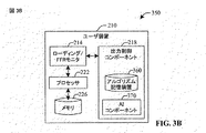
図3Aは、負荷インディケータの生成を決定するためにポリシー記憶装置310及び人工知能(AI:artificial intelligence)コンポーネント320を頼りにする基地局のブロック図300を図示する。ポリシー記憶装置310は、干渉測定規準が決定される時間インターバルΔt、及び負荷インディケータを生成する際に適用される干渉測定規準しきい値の大きさ、を決定するポリシーを含む。ポリシーは、FFRパターンにおいて利用される各副帯域に関するしきい値、又は複数の副帯域にわたる平均しきい値(下記参照)、を決定することができる。ポリシーが干渉管理に対するシステム応答の過去のデータに基づき時間のある期間にわたって変化できることが、注目され、変化は、適応性があり、例えば、決定した干渉測定規準に関するセクタの目標近くの変動の低減のような、より高いレベルの干渉制御、短い目標達成時間(time-to-target)(開始制御状態から目標値近くの大きさへの量の制御をもたらすために必要な制御の期間の初期調節時間)、及びその他、を達成するためにポリシーを最適化することをもたらす。ポリシーは、バックホール通信250を経由して本質的に異なるセクタの間で伝達されることができる。本質的に異なる隣接する基地局(例えば、2301−230N)が、干渉測定規準に基づいて負荷インディケータの生成のために本質的に異なるポリシーを有することがあり得ることは、認識されるはずであり、それゆえ全ての非取扱い基地局が同時に負荷インディケータ2461−246Nを通信することがない。ポリシー記憶装置310が独立型記憶コンポーネントとして図示されているが、メモリ242中に部分的に又は全体が存在できることは、さらに認識されるはずである。
FIG. 3A illustrates a block diagram 300 of a base station that relies on a
AIコンポーネント320は、通信の様々な態様、例えば、セル中のユーザの数、ユーザのタイプ(例えば、データ集中的なユーザ、待ち時間に敏感なユーザ、アクティビティの延長期間を有するユーザ、又は時折のユーザ)、気象条件及び地理的条件、同様に季節的な条件、例えば、春のあいだのセル内の植物の葉の増加、夏の雨、冬の大雪、及びその他、に基づいて干渉測定規準及び推定/予測干渉レベルについての過去のデータを収集することができる。干渉測定規準の推定/予測は、複数要因(multi-agent)モデル化理論又はゲーム理論、同様に他の高等数学アルゴリズム(下記参照)に基づくことができる。予測される干渉測定規準に基づいて、AIコンポーネント320は、負荷インディケータを生成するためにポリシーを変更できる。改訂されたポリシーは、基地局(例えば、非取扱いノードBJ230J)が特定のインターバルで干渉測定規準を決定し、そして特定の時間の期間(1日の、1月の、1年の特定の時間)のあいだに、特定の期間にわたり測定を保留したとしても、それらの時間インターバルを減少させる又はそれらを増加させることを要求することができる。それに加えて、改訂されたポリシーは、セクタが動作している副帯域に関する干渉測定規準しきい値の大きさを変更することができ、時間に依存するしきい値を結果としてもたらす。
The
本明細書で前に使用したように、そして主題の説明の他の部分で使用されるように、用語“知能(intelligence)”は、システムに関する既存の情報に基づいてシステムの現在の状態又は将来の状態に関する結論を理由づける、又は引き出す、例えば、推論する、能力を呼ぶ。人工知能は、人間の介在なしに特定の状況又は動作を同定するために、あるいはシステムの特定の状態の確率分布を生成するために利用されることが可能である。人工知能は、システム上の利用可能なデータ(情報)の集合に、高等数学アルゴリズム−例えば、判断ツリー、ニューラル・ネットワーク、回帰分析、クラスタ解析、遺伝学的(genetic)アルゴリズム、及び強化学習法−を適用することを頼りにする。 As used herein before, and as used elsewhere in the subject description, the term “intelligence” is based on existing information about the system, or the current state or future of the system. Calls the ability to reason or draw, eg, infer, conclusions about the condition of Artificial intelligence can be used to identify specific situations or actions without human intervention, or to generate probability distributions of specific states of the system. Artificial intelligence transforms the collection of available data (information) on the system into higher mathematical algorithms such as decision trees, neural networks, regression analysis, cluster analysis, genetic algorithms, and reinforcement learning methods. Rely on applying.
特に、負荷インディケータ生成のためのポリシーに関連して上記された様々な自動化された態様、及び本明細書中に記述される主題の発明に直接関連する他の自動化された態様の実現に対して、AIコンポーネント(例えば、コンポーネント320)は、データから学習するため、そして次にそのように構成されたモデルから推論を引き出すための複数の方法のうちの1つを利用することができ、そのモデルは、例えば、ハイデン・マルコフ・モデル(HMM:Hidden Markov Model)及び関連するプロトタイプの依存モデル、例えば、ベイジアン(Bayesian)モデル・スコア又は近似を使用した構造検索により生成されるベイジアン・ネットワークのようなより一般的な確率論的図式モデル、サポート・ベクトル機械(SVM:support vector machine)、“ニューラル・ネットワーク”法と呼ばれる方法のような非線形選別法、ファジー理論法、及びデータ融合を実行する他のアプローチ、等である。 In particular, for the implementation of the various automated aspects described above in connection with policies for load indicator generation, and other automated aspects that are directly related to the subject invention described herein. , The AI component (eg, component 320) can utilize one of a number of methods for learning from the data and then extracting inferences from the model so constructed, the model Is, for example, a Hidden Markov Model (HMM) and associated prototype dependency models, such as Bayesian networks generated by structural search using Bayesian model scores or approximations. A more general probabilistic schematic model, support vector machine (SVM), “ Non-linear sorting methods such as a method called “Neural Network” method, fuzzy logic methods, and other approaches to perform data fusion, etc.
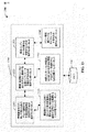
図3Bは、人工知能コンポーネントを頼りにして最適な出力調節/制御アルゴリズムを推論する出力制御コンポーネントを有する移動端末のブロック図350である。前に論じたように、制御アルゴリズムは、開制御ループ及び閉制御ループを含むことができ、それは出力調節を含み、負荷インディケータを決定するために使用される干渉測定規準の大きさに依存することができる、又は一定のオフセットであり得る。それに加えて、出力調節は、UE210により実行される少なくとも特定のアプリケーション及び/又はユーザ装置210により送信されるデータ、に基づいて推論されることができる。ある態様では、端末が無線オンライン・バンキングのようなデータに敏感なアプリケーションを実行するセクタに関して、出力の調節は、データの完全性がユーザにとって決定的でないアプリケーション(例えば、インターネット・ブラウジング/検索)のケースよりもっと積極的、例えば、より大きな出力調節オフセット、であることができ、そして通信セッションは、(一時的に)失われる/中断されることがある。別の1態様では、干渉測定規準の大きさと出力調節の間の様々な関係、及び干渉測定規準に基づくアルゴリズムは、セクタ内に存在する干渉の範囲に応じて使用されることができる。実施形態350において、アルゴリズム記憶装置は、出力制御コンポーネント218中に常駐する独立型コンポーネントであるが、記憶装置360は、UEのメモリ226中に一部又は全体が常駐することができることが、認識される。
FIG. 3B is a block diagram 350 of a mobile terminal having a power control component that relies on an artificial intelligence component to infer an optimal power regulation / control algorithm. As previously discussed, the control algorithm can include an open control loop and a closed control loop, which includes power regulation and depends on the magnitude of the interference metric used to determine the load indicator. Or can be a constant offset. In addition, power adjustments can be inferred based on at least a particular application executed by the
人工知能コンポーネント370は、上に述べた様々な変数に基づく出力調節を推論することが可能である。機械学習技術に基づいて、AIコンポーネント370は、最適出力オフセットを決定することができて、隣接するセクタにおいて悩まされる干渉を緩和することができる。移動端末210へのAIコンポーネントの追加は、複雑性を増加させるとはいえ、最適出力調節を推論することの利点は、その複雑さに関係するコストを相殺する。付加される複雑性に関係して、マルチ−コア・プロセッサ(例えば、プロセッサ222)は、UEを同時に動作させつつAIコンポーネントを動作させることの計算の要求を取り扱うために利用されることが可能である。プロセッサ222に関する他の代わりのアーキテクチャがAIコンポーネント(例えば、370)の効率的な動作のために利用されることが可能であることは、認識されるはずである。さらに、端末210により実行されるアプリケーションに応じて、端末のディスプレイ・グラフィックス処理ユニットは、音声のみの通信のケース又は低頻度ディスプレイ・リフレッシュによるデータ・アプリケーションのケース、等、のような、電話機中のグラフィカル・ユーザ・インターフェースがアクティブに使用されない間にAIコンポーネントを動作させることができる。
図4は、部分周波数再利用n/N=1/3を用いるセクタ化された無線通信セルを具備するシステム400を図示し、そこでは端末は負荷インディケータを選択的にデコードし/応答する。(基地局BS1−BS4(4201−4204)により取り扱われる)各セル402−408は、3つのセクタ4101−4103に区分され、これらのセクタのそれぞれは、セクタ4101−4103のそれぞれにおいて弁別的に満たすように図式的に示された周波数の1つのチャンク(副帯域)で動作する。3つのセクタだけが図示されているが、より多くの区切りのセクタ化が可能である。セクタ1 4101は、副帯域σ1−σ4(4301−4304)で動作し、セクタ2 4102は、帯域σ5−σ8(4305−4308)で、そしてセクタ3は、σ9−σ12(4309−43012)で動作する。利用可能なBWのより細かな又はより粗い副帯域分割は、可能である。基地局BS14201により取り扱われる端末440は、非取扱いセクタ1,2と3から(矢印で示される)負荷インディケータを受信する又は“聴取する”ことが可能であり、しかも、UE340がセクタ2と3により利用される周波数帯域σ1−σ8のいずれにおいても動作していないため、この端末は、そのようなセクタが過負荷でありそしてUEにおけるそれらに関係するFL SINRが大きい場合でさえも、セクタ2と3から発せられる負荷インディケータ(破線の矢印)をデコードしない/応答しない。
FIG. 4 illustrates a
上に述べたように、FFRパターン4101−4103及び対応する周波数は、時間インターバルΔτ450のあいだ維持されることができ、その後で、新たなFFRパターンが、各セクタを取り扱っている基地局により決定されることができる(例えば、FFRパターン更新)。FFRパターン変更の変化は、(複数の)新たなセクタの創生に応じて利用可能なシステム帯域幅を再区分すること、再利用を増加させること/減少させること、又はより大きな帯域幅動作へと切り替えること、特定のアプリケーション、例えば、端末ダウンローディング・ファイル、又は端末ストリーミング・ビデオ、を実行する特定の端末のために新たに追加された副帯域を利用すること、を含むことができる。FFR更新の結果として、端末440は、自身がデコードする負荷インディケータを変更することができる。
As stated above, the FFR patterns 410 1 -410 3 and corresponding frequencies can be maintained during the
図5Aは、出力制御のために利用される部分周波数再利用パターン及び干渉測定規準の決定を図示する。局在化したFFR及び非局在化FFRが示される。これらのFFRパターンのそれぞれは、時間インターバルΔτ450に広がる。FRRのそのような場合の両方において、システム帯域幅は、M個の副帯域に分割され、そしてN個のセクタはn=4の副帯域を割り当てられ、結果として4/Mの再利用をもたらす。n=4が、限定よりはむしろ説明及び例示の目的のために提示され、そしてnに関する別の選択が可能でありそして主題の明細のスコープの範囲内であることが、認識されるはずである。局在化したFFRにおいて、セクタに割り当てられた副帯域は、連続的でありそして特定の周波数インターバルを占有する、ところが、非局在化FFRにおいては、副帯域はインターリーブされる。図5Aの各副帯域がG個のサブキャリアを含むことができることが、認識されるはずである。干渉測定規準{Iσ;S}5101−510Mと5201−520Mは、副帯域σと対応するセクタSに関係付けられる。例として、集合{IM−7;N−1 510M−7,IM−6;N−1 510M−6,IM−5;N−1 510M−5,IM−4;N−1 510M−4}は、副帯域M−7からM−4までの干渉測定規準を含み、それはセクタN−1に対応する、これに対して、集合{IM;N 520M,IK+3;N 520K+3,IP+3;N 520P+3,I4;N 5204}。干渉測定規準5101−510Mと5201−520Mのそれぞれが、複数のサブキャリアにわたる平均に対応することができ、上に論じたように、そのような平均は干渉を決定する装置の分解能からもたらされることが、認識されるはずである。
FIG. 5A illustrates the determination of partial frequency reuse patterns and interference metrics used for power control. Localized FFR and delocalized FFR are shown. Each of these FFR patterns extends over a time interval Δτ450. In both such cases of FRR, the system bandwidth is divided into M subbands, and N sectors are allocated n = 4 subbands, resulting in 4 / M reuse. . It should be appreciated that n = 4 is presented for purposes of explanation and illustration rather than limitation, and that other choices for n are possible and are within the scope of the subject specification. . In localized FFR, subbands assigned to sectors are continuous and occupy a specific frequency interval, whereas in delocalized FFR, subbands are interleaved. It should be appreciated that each subband of FIG. 5A can include G subcarriers. The interference metrics {Iσ ; S } 510 1 -510 M and 520 1 -520 M are related to the sector S corresponding to the subband σ. As an example, the set {I M-7; N-1 510 M-7 , I M-6; N-1 510 M-6 , I M-5; N-1 510 M-5 , I M-4; N −1 510 M−4 } includes the interference metric from subband M−7 to M−4, which corresponds to sector N−1, whereas the set {I M; N 520 M , I K + 3; N 520 K + 3, I P + 3; N 520 P + 3, I 4;
1態様では、セクタS、例えば、セクタN、に割り当てられた副帯域に関係する干渉測定規準は、平均され、局在化したFFRに関して平均<I>1:L 4151−<I>N:L 515Nそして非局在化FFRに関して<I>1:D 5251−<I>N:D 525Nを導く。そのような平均は、干渉しきい値ITHと比較するため、そしてセクタにおける干渉測定規準がしきい値の上であるか下であるかどうかを判断するために利用されることが可能である。干渉測定規準の平均が、Δτ450よりも短い時間インターバルΔτ’のあいだに決定され得ることが、認識されるはずである。一例として、干渉は、事前に決められたレートで、例えば、無線フレーム又はスーパーフレーム(例えば、LTEで、無線フレーム間隔10ms)毎のようなフレームの特定の数毎の測定で、副帯域を精査することができる。精査レートは、様々なパラメータ、例えば、セル負荷及び/又はトラフィック、チャネル状態、等、にしたがって調節されることができる。
In one aspect, interference metrics related to subbands assigned to sector S, eg, sector N, are averaged and averaged for localized FFR <I> 1: L 415 1 − <I> N: For L 515 N and delocalized FFR, <I> 1: D 525 1 − <I> N: D 525 N is derived. Such an average can be utilized to compare to the interference threshold I TH and to determine whether the interference metric in the sector is above or below the threshold. . It should be appreciated that the average of the interference metric can be determined during a time interval Δτ ′ that is shorter than Δτ450. As an example, interference can scrutinize subbands at a predetermined rate, for example, by measuring every specific number of frames, such as every radio frame or superframe (eg LTE,
5151−515Nと5251−525Nのような複数の副帯域にわたる干渉測定規準の平均は、算術平均、幾何平均、又は調和平均であり得る。副帯域平均のそれぞれは、加重平均であり得て、例えば、算術平均では、セクタSに関係する各副帯域干渉測定規準Iσ;Sは、平均<I>S;a(a=L,D)を決定する前に、スカラ数である加重wσ;Sにより掛け算される。そのような平均は、プロセッサ238により計算されることができる。加重wσ;Sが機器応答のような系統的な要因を考慮することを可能にする、例えば、特定の周波数範囲の副帯域干渉測定規準の決定は、干渉測定規準の決定の際に、他の周波数範囲よりも低い精度で検査される。加重wσ;Sは、セクタSに割り当てられた帯域全体にわたって1に規格化され、そして周波数、時間、チャネル状態、セクタ負荷とトラフィック、及びその他に依存することがある。1つの態様では、加重は、加重の過去の値及び推論又は解析のために利用可能な過去のデータ又は現在のデータに基づいて、AIコンポーネント(例えば、コンポーネント320)によって決定される/推論されることができる。
The average of interference metrics across multiple subbands, such as 515 1 -515 N and 525 1 -525 N , can be an arithmetic average, a geometric average, or a harmonic average. Each of the subband averages can be a weighted average, for example, in arithmetic average, each subband interference metric I σ; S related to sector S is the average <I>S; ) Is multiplied by a weighted w σ; S which is a scalar number. Such an average can be calculated by the
図5Bは、周波数副帯域の関数として、干渉測定規準しきい値ITH及びそれぞれの論理値(例えば、“真”又は“偽”)を図示する。各副帯域4301−430Mは、干渉測定規準しきい値ITH5601−560Mを持ち、それは“真”/“偽”負荷インディケータに対応する干渉測定規準の範囲に影響を及ぼす。副帯域しきい値は、セクタ1からNに関係する副帯域の集合に関する平均しきい値<ITH>5701−570Mを導くことができる。そのような平均は、プロセッサ238により計算されることができる。そのような平均化は、局在化したFFR及び非局在化FFRに対して実行され得ることが、認識されるはずである。副帯域平均5701−570Nのそれぞれは、負荷インディケータの論理状態を示すことができる。時間が進むにつれ、しきい値5601−560Mと平均しきい値5701−570Mは、通信セクタ、例えば、4101−4103、において有効である新たなFFR再利用を反映するように変更することができる。平均<ITH>5701−570Mが、利用可能な周波数リソース(例えば、5101−510M)に関係するしきい値の算術平均、幾何平均、又は調和平均であり得ることは、認識されるはずである。それに加えて、前記平均は、加重の利用可能な過去の値により決定される平均化手法に入力される加重を用いる、加重平均であり得る。干渉測定規準しきい値ITH5601−560Mがその大きさを決定するポリシーを通して時間依存性があるので、平均しきい値5701−570Mも同様に時間依存性があることが、注目される。
FIG. 5B illustrates the interference metric threshold I TH and the respective logic values (eg, “true” or “false”) as a function of frequency subband. Each subband 430 1 -430 M has an interference metric threshold I TH 560 1 -560 M , which affects the range of interference metrics corresponding to “true” / “false” load indicators. The subband threshold can lead to an average threshold <I TH > 570 1 -570 M for the set of subbands related to
上に示されそして説明された例のシステムを考慮して、開示された主題にしたがって実行されることができるセル間出力制御に関する方法は、図6−8のフローチャートを参照してより良く認識されるであろう。説明の簡潔さの目的のために、方法は、一連のブロックとして示されそして説明されるとはいえ、あるブロックが本明細書中に図示されそして説明されるものとは異なる順番で及び/又は別のブロックと同時に起き得るので、特許請求される主題がブロックの数又は順番に限定されないことは、理解されそして認識されるべきである。その上、全ての図示されたブロックが、以降に記述される方法を実行するために必要とされ得るとは限らない。ブロックに関係付けられる機能が、ソフトウェア、ハードウェア、それらの組み合わせ、又はいずれかの他の好適な手段(例えば、デバイス、システム、プロセス、コンポーネント、...)により与えられ得ることが、認識される。それに加えて、以降にそして本明細書全体を通して開示される方法は、製造文書に記憶されることが可能であり、様々なデバイスへそのような方法を搬送すること及び伝達することを容易にすることが可能であることが、さらに認識されるはずである。ある方法が、代わりに、状態図におけるような一連の相互に関係する状態又は事象として表わされることを、当業者は、理解しそして認識するであろう。 In view of the example system shown and described above, methods related to inter-cell power control that can be performed in accordance with the disclosed subject matter are better appreciated with reference to the flowcharts of FIGS. 6-8. It will be. For purposes of brevity, the method is shown and described as a series of blocks, although certain blocks may be in a different order and / or than those shown and described herein. It should be understood and appreciated that claimed subject matter is not limited to the number or order of blocks, as they may occur concurrently with other blocks. Moreover, not all illustrated blocks may be required to implement the methods described below. It will be appreciated that the functionality associated with the blocks may be provided by software, hardware, a combination thereof, or any other suitable means (eg, device, system, process, component,...). The In addition, the methods disclosed hereinafter and throughout the present specification can be stored in manufacturing documents, facilitating transporting and communicating such methods to various devices. It should be further appreciated that it is possible. Those skilled in the art will understand and appreciate that a method may instead be represented as a series of interrelated states or events, such as in a state diagram.
図6は、部分周波数再利用の存在におけるセル間干渉に関連して負荷インディケータを決定するための方法600のフローチャートを示す。610では、干渉測定規準がモニタされる。干渉測定規準(例えば、干渉対熱雑音比、信号対干渉比、信号対雑音比、信号対干渉及び雑音比、及びその他)は、セクタの集合において発せられる干渉に関係する。一般的に、高い出力又はパワー・スペクトル密度で送信している端末は、生成される干渉の原因であり得る。620では、負荷インディケータは、しきい値に関連して干渉測定規準の大きさに基づいて決定される。干渉測定規準がしきい値を超える場合、負荷インディケータは、そのような関係を反映する論理状態、例えば、“真”、を採用する。同じように、干渉測定規準がしきい値より低い場合には、“偽”の論理状態が、負荷インディケータに割り当てられることができる。1つの態様では、干渉測定規準は、周波数の関数として決定されることができ、例えば、干渉測定規準は、周波数ドメインの特定の副帯域において決定される(図5A参照)。同様に、干渉測定規準は、時間、例えば、フレーム、スーパーフレーム、の関数として決定されることができる。別の態様では、干渉測定規準は、時間−周波数リソースの特定の集合の全体にわたる平均値であり得る。経験的な分解能のために、正確な干渉測定値でさえ、1つのフレームの1つのサブキャリアを精査するよりはむしろ、複数のサブキャリア及びフレームにわたる平均を含むことがあり得る。
FIG. 6 shows a flowchart of a
630では、負荷インディケータは、伝達される。通信のための2つの可能性のあるルート:(i)負荷インディケータを決定する基地局(例えば、非取扱いノードB1 2301)によるブロードキャストを経由するエアー・インターフェースを介したもの、及び(ii)バックホール・ネットワークを経由する負荷インディケータの送信によるもの、があり得る。1つの態様では、メカニズム(i)は、負荷インディケータの送信と取り扱われていない端末(例えば、UE440)における受信との間の通信待ち時間にわずかしか影響しないという利点を提供する。重大な待ち時間がないことは、負荷インディケータに関係する干渉測定規準の大きさを減少させるために必要な端末における出力制御に関する応答時間を改善する。メカニズム(ii)は、チャネル状態に敏感でないという利点を提供し、その理由は、通信が、T1/E1回線又はT−キャリア/Eキャリア・プロトコルの他の回線のような通信回線を利用する、及び/又はパケットに基づくインターネット・プロトコルを利用する、有線又は光ファイバ・ネットワーク・バックボーンを経由した基地局のあいだの2点間(例えば、2301と260)であるためである。チャネル状態に敏感でないことは、干渉を減少させるために必要な出力調節を確実にすることで、負荷インディケータが適正に受信されそして処理されることを確実にすることができる。しかしながら、負荷インディケータのバックホール通信が著しい待ち時間を招き得ることは、認識されるはずである。それにも拘らず、端末により実行されるアプリケーションに応じて、出力調節及び干渉制御/緩和における遅延が、許容され得る。 At 630, the load indicator is communicated. Two possible routes for communication: (i) over the air interface via broadcast by the base station that determines the load indicator (eg non-serving node B1 230 1 ), and (ii) back There may be due to the transmission of a load indicator via the whole network. In one aspect, mechanism (i) provides the advantage that it only slightly affects the communication latency between the transmission of the load indicator and the reception at the unhandled terminal (eg, UE 440). The absence of significant latency improves the response time for power control at the terminal needed to reduce the magnitude of the interference metric associated with the load indicator. Mechanism (ii) provides the advantage of being insensitive to channel conditions because the communication utilizes a communication line, such as a T1 / E1 line or other lines of the T-carrier / E carrier protocol, and utilizing / or Internet protocol packet-based, between two points between the base station via a wired or fiber optic network backbone (e.g., 230 1 and 260) because it is. Being insensitive to channel conditions can ensure that the load indicator is properly received and processed by ensuring the necessary power adjustments to reduce interference. However, it should be appreciated that the backhaul communication of the load indicator can lead to significant latency. Nevertheless, delays in power adjustment and interference control / mitigation can be tolerated depending on the application being executed by the terminal.
図7は、部分周波数再利用の存在においてセル間出力制御のための方法700のフローチャートを示す。710では、端末(例えば、UE440)は、該端末に割り当てられた周波数帯域において動作する最も強い非取扱いセクタから発せられる負荷インディケータ(例えば、負荷インディケータ246J)を受信し、そしてデコードする。端末が動作する周波数帯域で非取扱いセクタが動作するという必要条件は、部分周波数再利用をセル間出力制御へと組み込むことを提供する。そのような周波数弁別は、端末が重大な干渉を実際に与えることがあるセクタの負荷インディケータを端末が処理することを可能にできる。“最も強い”非取扱いセクタは、最高のチャネル状態、例えば、ダウンリンク(又は順方向リンク)送信における最大のSINR、で端末に送信している非取扱い基地局に対応する。1つの態様では、複数の非取扱い基地局の順方向リンクSINRが実質的に同じであるか、又は許容範囲内である場合には、端末は、そのような複数の非取扱いセクタの負荷インディケータをデコードすることができ、そしてこれらの非取扱いセクタの順方向リンクSINRを考慮すること(例えば、対応する加重として順方向リンクSINRを用いて負荷インディケータの加重平均を見つけ、そして次にその加重平均をしきい値と比較して実効的な負荷インディケータを生成すること)により、及び/又は非取扱いセクタの通信状態の付加的な特性、例えば、負荷インディケータを送信しているセクタにより取り扱われているセルにおけるユーザの数、を考慮することにより出力に関する統合された実効的な負荷インディケータを決定する。そのような実効的な負荷インディケータが最も強い非取扱いセクタに関係付けられる負荷インディケータの代わりをすることが、注目される。負荷インディケータの論理状態−例えば、受信した干渉測定規準がしきい値を超えるケースでは“真”、又はその測定規準がしきい値より低いケースでは“偽”−は、720において調べられる。負荷インディケータが“真”であるケースでは、730において、端末は、自身の送信パワー・スペクトル密度(PSD)レベルを低くする、ところが、負荷インディケータが“偽”である場合、740において、端末は自身の送信PSDレベルを増加させる。1つの態様では、そのような出力制御は、端末内の出力制御コンポーネント、例えば、コンポーネント218、を通してもたらされることができる。
FIG. 7 shows a flowchart of a
図8は、取扱い基地局を経由したセル間出力制御のための方法800のフローチャートを示す。810では、隣接する非取扱いセクタにより発行される負荷インディケータの集合が、バックホール・ネットワーク通信を経由して受信される。そのような通信は、通信が有線(例えば、撚線対(twisted pair)、光ファイバ、及びその他)ネットワーク・バックボーンを介して行われるので、遠く離れた非取扱いセクタが悪いチャネル状態にあっても、負荷インディケータを伝達することを可能にする。1つの態様では、そのような通信は、パケット交換、(UMBのケースであるような)インターネット・プロトコル(IP)に基づくものであり得る。820では、受信した負荷インディケータは、処理され/デコードされ、取扱いセクタ(例えば、4101)において動作する端末(例えば、440)に割り当てられている同じ周波数副帯域で動作するセクタからどのようなインディケータが発せられるか、そしてそれらの論理状態を決定する。830では、該端末と同じ周波数インターバルで動作する実質的に全ての強い(例えば、高いFL SINR)非取扱いセクタからの負荷インディケータを考慮した統合された実効的な負荷インディケータは、エアー・インターフェースを介して伝達される。あるいは、840において、新たな送信PSDが、(例えば、スケジューラ264を経由して)端末に割り当てられる。そのような割り当ては、端末210中の出力制御コンポーネント218の機能及びUEの送信出力の制御に関連して本明細書中で前に論じたものと同様な方法で行われる。
FIG. 8 shows a flowchart of a
次に、FFRの存在における出力制御のための方法例700が、シミュレーションを通して説明される。モデル化される無線通信システムは、3−セクタ・セル(図3参照)を有する総合的な(wrap-around)レイアウト中に19のノードBを備える。干渉は10ms毎に(それはLTEにおける無線フレームに対応する)精査される。それに加えて、10個の端末が、各セクタに存在し、最大3km/hの速度を有し、そして全バッファ・トラフィック・モデルを有する:各端末は比例公平スケジューリング(proportional fair scheduling)にしたがってスケジューリングされる。5MHzのシステム帯域幅は、部分周波数再利用2/3の下で12の副帯域σ1−σ12に分割される;各帯域は25のサブキャリアを含む。図9Aは、シミュレーションにおいて利用される周波数再利用表を図示する。黒丸(910)と白丸(920)は、それぞれ、セクタに対して禁止された副帯域と利用可能な副帯域を示す。システムBWは、N=12のチャンクに分割され、そして各セクタ4101−4103は、n=8の副帯域を割り当てられ、そのうちの4個は、セクタの複数の対に同時に割り当てられる。そのような再利用が副帯域を共有するセクタにおける干渉の増加を結果としてもたらすことが、認識されるはずであり、より多くの数のサブキャリアが通信のために利用されるので、データ送信レートは、各セクタにおいて増加されることができる。さらに、別のFFRパターンは、本明細書中で下記に示されるような、実質的に同じ事実(findings)を用いて、シミュレーションにおいて利用されることが可能である。さらに現在のところ、下記に示されるシミュレーション結果は、エアー・インターフェースを介して送信された負荷インディケータ(例えば、2461−246N)に対応する;しかしながら、負荷インディケータがバックホール・ネットワーク(例えば、250)を経由して伝達されるケースにおいて、定性的に同じ結果が、予想されることができる。
Next, an
図9Bは、基地局において決定される時間の関数としての干渉測定規準(干渉適応(interference adaption))のプロット950を図示する。プロット950は、FFRを取り込んでいる主題のセル間出力制御法700、ここではPC−1と名付けられる、及びFFRを取り込んでいない従来のセル間出力制御アルゴリズム(PC−2)の性能を比較する。従来の方式PC−2を利用するとき、端末(例えば、UE440)は、無線通信システムにおいて適用されるFFRパターンを知らない、対照的に、主題のアルゴリズムPC−1は、端末動作のためにスケジューリングされた周波数副帯域において動作しているセクタにより伝達される適切な負荷インディケータを(周波数ドメインにおいて)選択的にデコードするために、UEが基底にあるFFRインプランテーション(implantation)を知っていることを必要とする。上に論じたように、PC−2内では、UE440のような端末は、デコーディングを実行している端末とは実質的に全く異なる周波数帯域を実際に利用することが可能である自身に隣接する非取扱いセクタにより生成される負荷インディケータをデコードする。シミュレーションでは、干渉測定規準は、熱雑音で割り算した干渉(IoT:interference-over-thermal noise)に対応し、そして干渉測定規準しきい値ITH=(IoT)TH960は、4.41dBに設定される;しかしながら、実質的に任意の別の値がしきい値として設定され得ることが認識されるはずである。その上、12の副帯域が通信のために利用可能であるとしても、1つのしきい値が、シミュレーションにおいて使用される。各セクタにおいてシミュレーションされた干渉測定規準は、セクタ対して利用可能である(8の)副帯域にわたり平均され、そして次にITH960と比較される。他の干渉測定規準がシミュレーションにおいて利用されることができ、そしてプロット950に図示されたものと実質的に同じ結果をもたらすことが、注目される。すなわち、PC−1は、無線システムにおけるIoTの正確な制御へと導き、ほぼ800スロットの調節インターバルτmin970(例えば、LTEでは、スロットは0.5ms間隔である)の後の少なくとも5000スロットの期間にわたり目標しきい値(IoT)TH=4.41dBの近くで4dBの範囲内に留まる変動を有する。
FIG. 9B illustrates a
プロット950から、従来の出力制御法PC−2がIoTを制御できないことが、認識され得る。調節期間の後で、IoTは、設定したしきい値ITH=4.41dB960の近くで最小値に到達し、そして徐々に増加し、目標ITH960を上回る〜8dBのIoT平均値のまわりで約6−7dBの変動を示す。そのような適正な制御の欠如の起源は、PC−2方式において、周波数弁別がないことであり、それゆえ、負荷インディケータが端末(例えば、UE440)によりデコードされるときに、そのインディケータは、端末のPSDレベルに関係しない−PSDレベルは、端末に対してスケジューリングされた送信出力と端末に割り当てられたサブキャリアの数及び周波数との比により決定される。端末のPSDレベルは、FFRパターンを負荷インディケータの処理へと取り込むことを通して、PC−1において考慮される。それゆえ、セル間出力制御は、PC−2に対して改善される。
From
図9Cは、本明細書に開示された出力制御PC−1及び従来の出力制御法PC−2に関する端末(例えば、UE440)スループットのシミュレーションされた累積分布関数(CDF)のプロット980を表示する。上記のように、図9Aと関連して、シミュレーションされた無線通信システムは、57のセクタ内に一様に配置された570のUEを備える。シミュレーションにおける他のパラメータは、上記のものと同じである。主題のアルゴリズムPC−1(700、図7)が従来のアルゴリズムPC−2を凌ぐことは、プロット980から容易に明らかである。PC−1とPC−2に関するセクタにおける平均IoTレベル<IoT>、及び平均セクタ・スループット<η>の直接比較は、<IoT>(PC−1)=4.43dBそして<η>(PC−1)=2.75Mbpsであり、ところが<IoT>(PC−2)=8.06dBそして<η>(PC−2)=2.23Mbpsであることを明らかにする。主題の出力制御アルゴリズム(PC−1)は、従来のアルゴリズムPC−2と比較したときに、干渉レベルの著しい減少そしてセクタ・スループットの増加を結果としてもたらす。
FIG. 9C displays a simulated cumulative distribution function (CDF)
図9A、図9Bと図9Cをまとめると、部分周波数再利用がLTEのような無線通信システムのアップリンクにおいて適用されるとき、従来のセル間出力制御アルゴリズムは効果的に動作しないことが注目される。出力制御に関する開示された方式は、FFRの存在において基地局における干渉測定規準レベル(IoTで示される)の効率的且つ正確な制御を結果としてもたらし、一方でセクタ・スループットを最適化する。 To summarize FIGS. 9A, 9B and 9C, it is noted that conventional inter-cell power control algorithms do not work effectively when partial frequency reuse is applied in the uplink of wireless communication systems such as LTE. The The disclosed scheme for power control results in efficient and accurate control of the interference metric level (denoted IoT) at the base station in the presence of FFR, while optimizing sector throughput.
図10は、多入力多出力(MIMO:multiple-input multiple-output)システムにおける送信機システム1010(例えば、基地局260、又はBS2301−230Nのいずれか)及び受信機システム1050(例えば、アクセス端末240)の実施形態のブロック図1000であり、それは本明細書中に記述した1又はそれより多くの態様−例えば、FFRの存在においてセル間出力制御が図7、図8と図9に関連して本明細書中で前に記述したように生じることがある−にしたがった無線通信環境においてセル/セクタ通信を提供することが可能である。送信機システム1010において、複数のデータ・ストリームに関するトラフィック・データは、データ・ソース1012から送信(TX)データ・プロセッサ1014へ与えられることができる。ある実施形態では、各データ・ストリームは、それぞれの送信アンテナを経由して送信される。TXデータ・プロセッサ1014は、データ・ストリームに対して選択される特定のコーディング方式に基づいて各データ・ストリームに関するトラフィック・データをフォーマット化し、コード化し、そしてインターリーブして、コード化されたデータを与える。各データ・ストリームに関するコード化されたデータは、OFDM技術を使用してパイロット・データにより多重化されることができる。パイロット・データは、一般的に既知のデータ・パターンであり、それは既知の方法で処理されそして受信機システムにおいて使用されることができチャネル応答を与える。各データ・ストリームに関する多重化されたパイロット・データとコード化されたデータは、次に、そのデータ・ストリームに対して選択される特定の変調方式(例えば、2相位相変調(BPSK)、4相位相変調(QPSK)、多相位相変調(M−PSK)、又はm−次直交振幅変調(M−QAM))に基づいて変調される(例えば、シンボル・マッピングされる)。各データ・ストリームに関するデータ・レート、コーディング及び変調は、プロセッサ1030により実行される命令によって決定されることができ、データと同様にその命令はメモリ1032中に記憶されることができる。
FIG. 10 illustrates a transmitter system 1010 (eg, either
全てのデータ・ストリームに関する変調シンボルは、次に、TX MIMOプロセッサ1020へ与えられ、それは変調シンボル(例えば、OFDM)をさらに処理することができる。TX MIMOプロセッサ1020は、次に、NT個の変調シンボル・ストリームをNT個のトランシーバ(TMTR/RCVR)1022Aから1022Tへ与える。ある種の実施形態では、TX MIMOプロセッサ1020は、データ・ストリームのシンボルに及びそのシンボルがそこから送信されようとしているアンテナにビームフォーミング加重(又はプリコーディング)を適用する。各トランシーバ1022は、それぞれのシンボル・ストリームを受信しそして処理して、1又はそれより多くのアナログ信号を与え、そしてそのアナログ信号をさらに調整して(例えば、増幅し、フィルタで処理し、そしてアップコンバートして)MIMOチャネルを介した送信のために適している変調された信号を与える。トランシーバ1022Aから1022TからのNT個の変調された信号は、次に、それぞれNT個のアンテナ10241から1024Tから送信される。受信機システム1050では、送信された変調信号は、NR個のアンテナ10521から1052Rにより受信され、そして各アンテナ1052からの受信信号は、それぞれのトランシーバ(RCVR/TMTR)1054Aから1054Rへ与えられる。各トランシーバ10541−1054Rは、それぞれの受信信号を調整し(例えば、フィルタで処理し、増幅し、そしてダウンコンバートし)、調整した信号をディジタル化してサンプルを与え、そしてそのサンプルをさらに処理して、対応する“受信した”シンボル・ストリームを与える。
The modulation symbols for all data streams are then provided to TX MIMO processor 1020, which can further process the modulation symbols (eg, OFDM). TX MIMO processor 1020 then provides N T modulation symbol streams to N T transceivers (TMTR / RCVR) 1022 A through 1022 T. In certain embodiments, TX MIMO processor 1020 applies beamforming weights (or precoding) to the symbols of the data stream and to the antenna from which the symbols are to be transmitted. Each
RXデータ・プロセッサ1060は、次に、特定の受信機処理技術に基づいてNR個のトランシーバ10541−1054RからのNR個の受信シンボル・ストリームを受信しそして処理して、NT個の“検出した”シンボル・ストリームを与える。RXデータ・プロセッサ1060は、次に、各検出したシンボル・ストリームを復調し、逆インターリーブし、そしてデコードして、データ・ストリームに関するトラフィック・データを再生する。RXデータ・プロセッサ1060による処理は、送信機システム1010においてTX MIMOプロセッサ1020及びTXデータ・プロセッサ1014により実行されたものと相補的である。プロセッサ1070は、どのプリコーディング行列を使用するかを定期的に判断する、その行列は、メモリ1072中に記憶されることが可能である。プロセッサ1070は、行列インデックス部分とランク値部分を含んでいる逆方向リンク・メッセージを定式化する。メモリ1072は、プロセッサ1070により実行されたときに逆方向リンク・メッセージの定式化を結果としてもたらす命令を記憶することができる。逆方向リンク・メッセージは、通信リンク又は受信したデータ・ストリーム、あるいはそれらの組み合わせに関する様々なタイプの情報を備えることができる。一例として、そのような情報は、調節された通信リソース、スケジューリングされたリソースを調節することに関するオフセット、データ・パケット・フォーマットをデコーディングするための情報、を備えることができる。逆方向リンク・メッセージは、次に、TXデータ・プロセッサ1038により処理され、それはデータ・ソース1036から複数のデータ・ストリームに関するトラフィック・データを同様に受信し、変調器1080により変調され、トランシーバ1054Aから1054Rにより調整され、そして送信機システム1010へと送信されて戻される。
送信機システム1010では、受信機システム1050からの変調された信号は、アンテナ10241−1024Tにより受信され、トランシーバ1022A−1022Tにより調整され、復調器1040により復調され、そしてRXデータ・プロセッサ1042により処理されて、受信機システム1050により送信された逆方向リンク・メッセージを抽出する。プロセッサ1030は、次に、ビームフォーミング加重を決定するためにどのプリコーディング行列を使用するかを決定し、そして抽出したメッセージを処理する。
At
単一ユーザ(SU:single-user)MIMOモードの動作は、図10に示されたようにそして上に記述された動作にしたがう、1つの受信機システム1050が送信機システム1010と通信するケースに対応する。主題のモードの動作では、セル間出力は本明細書で前に記述したように実現されることができる。SU−MIMOシステムでは、NT個の送信機10241−1024T(TXアンテナとしても知られる)及びNR個の受信機10521−1052R(RXアンテナとしても知られる)は、無線通信のための行列チャネル(例えば、レーリー・チャネル、又はガウシアン・チャネル)を形成する。SU−MIMOチャネルは、ランダム複素数のNR×NT行列により記述される。チャネルのランク(rank)は、NR×NTチャネルの算術ランクに等しくなる。空間−時間コーディング、又は空間−周波数コーディングにおいて、ランクは、チャネルを経由して送られるデータ・ストリームの数、又は層の数に等しい。ランクが多くともmin{NT,NR}に等しいことが、認識されるはずである。NT個の送信アンテナとNR個の受信アンテナにより形成されるMIMOチャネルは、NV個の別々のチャネルへと分解されることができ、それは空間チャネルとも呼ばれる、ここで、NV≦min{NT,NR}である。
Single-user (SU) MIMO mode operation is in the case where one
1つの態様では、トーンωにおいて、OFDMを用いて送信される/受信されるシンボルは、次式によりモデル化されることができる:
y(ω)=H(ω)c(ω)+n(ω) (1)
ここで、y(ω)は、受信したデータ・ストリームであり且つNR×1ベクトルであり、H(ω)は、トーンωにおけるチャネル応答NR×NT行列(例えば、時間依存チャネル応答行列hのフーリエ変換)であり、c(ω)は、NT×1出力シンボル・ベクトルであり、そしてn(ω)は、NR×1雑音ベクトル(例えば、付加的白色ガウス・ノイズ)である。プリコーディングは、NV×1層ベクトルをNT×1プリコーディング出力ベクトルへ変換することができる。NVは、送信機1010により送信されたデータ・ストリーム(層)の実際の数であり、そしてNVは、少なくとも一部は端末により報告されるランク及びチャネル状態に基づいて送信機(例えば、アクセス・ポイント250)の判断においてスケジューリングされることができる。c(ω)が送信機により適用される少なくとも1つの多重化方式、及び少なくとも1つのプリコーディング(又はビームフォーミング)方式の結果であることが、認識されるはずである。それに加えて、c(ω)は、出力利得行列を用いて畳み込まれる、それは送信機1010が各データ・ストリームNVを送信するために割り当てる出力の大きさを決定する。そのような出力利得行列が、アクセス端末240に割り当てられるリソースであり得て、そして本明細書中で記述したように出力オフセットの調節を通して管理され得ることが、認識されるはずである。無線チャネルのFL/RL相互関係の観点から、MIMO受信機1050からの送信が、実質的に同じ要素を含んでいる式(1)の方式で同様にモデル化されることができることが、認識されるはずである。それに加えて、受信機1050は、逆方向リンクにおいてデータを送信することの前にプリコーディング方式を同様に適用することができる。
In one aspect, symbols transmitted / received using OFDM in tone ω can be modeled by the following equation:
y (ω) = H (ω) c (ω) + n (ω) (1)
Where y (ω) is the received data stream and is an N R × 1 vector, and H (ω) is the channel response N R × N T matrix (eg, time-dependent channel response matrix in tone ω) h (Fourier transform of h ), c (ω) is the N T × 1 output symbol vector, and n (ω) is the N R × 1 noise vector (eg, additional white Gaussian noise). . Precoding can convert an N V × 1 layer vector to an N T × 1 precoding output vector. N V is the actual number of data streams (layers) transmitted by the
システム1000(図10)では、NT=NR=1のとき、システムは、単一入力単一出力(SISO:single-input single-output)システムへと縮小し、それは本明細書中に説明される1又はそれより多くの態様にしたがった無線通信環境におけるセクタ通信を提供することができる。あるいは、単一入力多出力(SIMO:single-input multiple output)モードの動作は、NT>1とNR=1に対応する。さらに、並列の複数の受信機が送信機システム1010と通信するとき、マルチユーザ(MU:multiuse)MIMOモードの動作が、設定される。本明細書中で記述した態様にしたがうFFRの存在におけるセル間出力制御は、上記のモードの動作のそれぞれにおいて利用されることができる。
In system 1000 (FIG. 10), when N T = N R = 1, the system scales down to a single-input single-output (SISO) system, which is described herein. Sector communication in a wireless communication environment can be provided in accordance with one or more aspects described. Alternatively, single-input multiple output (SIMO) mode operation corresponds to N T > 1 and N R = 1. Further, when a plurality of parallel receivers communicate with the
図11は、明細書中に説明される様々な態様にしたがって、セル間干渉測定規準に関係する出力制御をもたらしそして負荷インディケータをモニタするシステム1100のブロック図である。一例では、システム1100は、アクセス端末1102を含む。図示されるように、アクセス端末1102は、1又はそれより多くのアクセス・ポイント1104からの(複数の)信号を受信し、そしてアンテナ1108を介して1又はそれより多くのアクセス・ポイント1104へ送信することができる。それに加えて、アクセス端末1102は、アンテナ1108から情報を受信する受信機1110、又は、実質的に任意の他の電子機器、を備えることができる。一例では、受信機1110は、受信した情報を復調する復調器(Demod)に動作上で関係付けられることができる。復調されたシンボルは、次にプロセッサ1114により解析されることができる。プロセッサ1114は、メモリ1116に接続されることができ、それはアクセス端末1102に関連するデータ及び/又はプログラム・コードを記憶することができる。その上、アクセス端末1002は、プロセッサ1114を利用して、方法700、及び/又は他の適切な方法を実行することができる。アクセス端末1002は、変調器1118を同様に含むことができ、それは1又はそれより多くのアクセス・ポイント1104へアンテナ1108を介して送信機1120による送信のための信号を多重化することができる。
FIG. 11 is a block diagram of a
図12は、本明細書中で説明する様々な態様による無線通信システムにおいて、負荷インディケータを生成し、負荷インディケータを搬送し、同様に端末及び他の逆方向リンク・リソースへの出力レベルをスケジューリングすることを容易にする一例のシステム1200のブロック図である。一例では、システム1200は、基地局すなわちアクセス・ポイント1202を含む。図示されるように、アクセス・ポイント1202は、受信(Rx)アンテナ1206を介して1又はそれより多くのアクセス端末1204から(複数の)信号を受信し、そして送信(Tx)アンテナ1208を介して1又はそれより多くのアクセス端末1204へ送信することができる。
FIG. 12 is a wireless communication system in accordance with various aspects described herein for generating load indicators, carrying load indicators, and similarly scheduling power levels to terminals and other reverse link resources. 1 is a block diagram of an
それに加えて、アクセス・ポイント1202は、受信アンテナ1206から情報を受信する受信機1210を備えることができる。一例では、受信機1210は、受信した情報を復調する復調器(Demod)、又は、実質的に任意の他の電子機器、に動作上で関係付けられることができる。復調されたシンボルは、次にプロセッサ1214により解析されることができる。プロセッサ1214は、メモリ1216に接続されることができ、それはコード・クラスタに関連する情報、アクセス端末割り当て、それに関連するルックアップ・テーブル、固有のスクランブリング系列、及び/又は他の妥当なタイプの情報を記憶することができる。アクセス・ポイント1102は、変調器1218を同様に含むことができ、それは1又はそれより多くのアクセス端末1204へ送信アンテナ1208を経由する送信機1220による送信のための信号を多重化することができる。
In addition, the
次に、開示された主題の複数の態様を動作可能にするシステムが、図13と図14に関連して説明される。そのようなシステムは、プロセッサ、又は電子機器、ソフトウェアあるいはそれらの組み合わせ(例えば、ファームウェア)により与えられる機能を表す機能ブロックであり得る複数の機能ブロックを含むことができる。 Next, a system that enables multiple aspects of the disclosed subject matter will be described in conjunction with FIGS. Such a system can include a plurality of functional blocks that can be functional blocks representing functions provided by a processor, or electronics, software, or a combination thereof (eg, firmware).
図13は、本願の開示の態様にしたがった無線通信において負荷インディケータの生成を可能にする一例のシステムのブロック図を図示する。システム1300は、少なくとも一部分が無線基地局(例えば、アクセス・ポイント2301−230N、又は260)内に存在することができる。システム1300は、共同して動作することが可能である複数の電子コンポーネントの論理回路グループ1310を含む。1つの態様では、論理回路グループ1310は、無線通信セクタにおいて発せられる干渉に関係する干渉測定規準を決定するための電子コンポーネント1315、時間−周波数リソースにおける干渉測定規準に関係する負荷インディケータを発生するための電子コンポーネント1325、負荷インディケータの集合を受信するための電子コンポーネント1335、及びパワー密度割り当てをスケジューリングするための電子コンポーネント1345を含む。それに加えて、システム1300は、電子コンポーネント1315に直接接続され、時間インターバルを設定してセクタにおける干渉を精査するポリシーを採用するための電子コンポーネント1355、及びコンポーネント1325に直接接続され、周波数リソース全体にわたる干渉測定規準に関するしきい値の集合を設定するポリシーを採用するための電子コンポーネント1365、を含むことができる。
FIG. 13 illustrates a block diagram of an example system that enables generation of load indicators in wireless communications in accordance with aspects of the present disclosure.
システム1300は、しかも電子コンポーネント1315,1325,1335,1345,1355と1365に関係する機能を実行するための命令、同様にそのような機能を実行している間に生成されることができる測定されたデータ及び計算されたデータ、を保持するメモリ1370を含むことが可能である。メモリ1370の外部であるように示されているとはいえ、電子コンポーネント1315,1325と1335,1345,1355と1365のうちの1又はそれより多くがメモリ1370内に存在することが可能であることは、理解されるはずである。
The
図14は、本願の開示の態様にしたがって負荷インディケータを受信すること及びデコードすることを可能にし、同様に送信出力を調節することを可能にする一例のシステムのブロック図を図示する。システム1400は、少なくとも一部が、無線基地局(例えば、アクセス端末210)内に存在することが可能である。システム1400は、共同して動作することが可能である電子コンポーネントの論理回路グループ1410を含む。1つの態様では、論理回路グループ1410は、干渉測定規準の大きさに関係する負荷インディケータ、該負荷インディケータは非取扱いセクタにおいて発せられる、を受信するための電子コンポーネント1415、アクセス端末に割り当てられた部分周波数再利用で動作する最大の信号対干渉及びノイズ比を有する非取扱いセクタに対応する負荷インディケータをデコードするための電子コンポーネント1425、及びデコードされた負荷インディケータに応じて移動端末の送信パワー・スペクトル密度を調節するための電子コンポーネント1435を含む。
FIG. 14 illustrates a block diagram of an example system that enables receiving and decoding load indicators according to aspects of the present disclosure, as well as adjusting transmit power.
システム1400は、電子コンポーネント1415,1425と1435に関係する機能を実行するための命令、同様にそのような機能を実行している間に生成されることができる測定されたデータ及び計算されたデータ、を保持するメモリ1440を同様に含むことが可能である。メモリ1340の外部であるように示されているとはいえ、電子コンポーネント1415,1425と1435のうちの1つ又はそれより多くがメモリ1440内に存在することが可能であることは、理解されるはずである。
ソフトウェア・インプリメンテーションに関して、本明細書中に記述された技術は、本明細書中に記述された機能を実行するモジュール(例えば、手順、機能、及びその他)を用いて実行されることができる。ソフトウェア・コードは、メモリ・ユニット中に記憶されることができ、そしてプロセッサによって実行されることができる。メモリ・ユニットは、プロセッサの内部に、又はプロセッサの外部に与えられることができる。外部の場合には、この分野で公知の種々の手段を介してプロセッサに通信で接続されることが可能である。 With respect to software implementation, the techniques described herein can be implemented using modules (eg, procedures, functions, and so on) that perform the functions described herein. . Software code can be stored in a memory unit and executed by a processor. The memory unit can be provided inside the processor or external to the processor. If external, it can be communicatively connected to the processor via various means known in the art.
本明細書中に記載される様々な態様又は構成は、方法、装置、又は標準プログラミング技術及び/又は標準エンジニアリング技術を使用する製造のアーティクル(article)として与えられることができる。本明細書中で使用されるように用語“製造のアーティクル”は、いずれかのコンピュータ読み取り可能なデバイス、キャリア、又は媒体からアクセス可能なコンピュータ・プログラムを含むように意図されている。例えば、コンピュータ読み取り可能な媒体は、磁気的な記憶デバイス(例えば、ハード・ディスク、フロッピー(登録商標)ディスク、磁気テープ、等)、光ディスク(例えば、コンパクト・ディスク(CD)、ディジタル・ヴァーサタイル・ディスク(DVD:digital versatile disk)、等)、スマート・カード、及びフラッシュ・メモリ・デバイス(例えば、EPROM、カード、スティック、キー・ドライブ、等)、を含むことができるが、それらに限定されない。それに加えて、本明細書中に記述される様々な記憶媒体は、情報を記憶するための1又はそれより多くのデバイス及び/又は機械読取り可能な媒体を表すことができる。用語“機械読取り可能な媒体”は、(複数の)命令及び/又はデータを記憶すること、を含むこと、搬送することが可能である無線チャネル及び様々な他の媒体を、これらに限定されることなく含むこと、ができる。 Various aspects or configurations described herein may be provided as a method, apparatus, or article of manufacture using standard programming and / or standard engineering techniques. The term “article of manufacture” as used herein is intended to include a computer program accessible from any computer-readable device, carrier, or medium. For example, computer readable media include magnetic storage devices (eg, hard disks, floppy disks, magnetic tapes, etc.), optical disks (eg, compact disks (CD), digital versatile disks, etc. Disk (DVD: digital versatile disk, etc.), smart card, and flash memory device (eg, EPROM, card, stick, key drive, etc.), but are not limited thereto. In addition, various storage media described herein can represent one or more devices and / or machine-readable media for storing information. The term “machine-readable medium” includes, but is not limited to, storing wireless command (s) and / or data, wireless channels and various other media that can be carried. Can be included without.
本明細書中で使用されるように、用語“プロセッサ”は、古典的なアーキテクチャ又は量子コンピュータを呼ぶことができる。古典的なアーキテクチャは、単一−コア・プロセッサ、ソフトウェア・マルチスレッド実行能力を有する単式プロセッサ、マルチ−コア・プロセッサ、ソフトウェア・マルチスレッド実行能力を有するマルチ−コア・プロセッサ、ハードウェア・マルチスレッド技術を有するマルチ−コア・プロセッサ、並列プラットフォーム、及び分散型共有メモリを有する並列プラットフォームを具備するが、これらを具備することに限定されない。それに加えて、プロセッサは、集積回路、用途特定集積回路(ASIC:application specific integrated circuit)、ディジタル信号プロセッサ(DSP:digital signal processor)、フィールド・プログラマブル・ゲートアレイ(FPGA:field programmable gate array)、プログラマブル論理コントローラ(PLC:programmable logic controller)、複合プログラマブル論理デバイス(CPLD:complex programmable logic device)、ディスクリート・ゲート論理回路又はトランジスタ論理回路、ディスクリート・ハードウェア・コンポーネント、又は本明細書中で記述した機能を実行するために設計されたこれらの組み合わせ、を呼ぶことができる。量子コンピュータ・アーキテクチャは、ゲートされた又は自己組み込みの量子ドット中に包含されるキュービット(qubit)、核磁気共鳴プラットフォーム、超電導ジョセフソン(Josephson)接合、等、に基づくことができる。プロセッサは、ユーザ装置の空間使用量を最適化するため、又は性能を向上させるために、例えば、分子ベース及び量子−ドット・ベースのトランジスタ、スイッチ及びゲートのような、ナノ−スケール・アーキテクチャを利用することが可能であるが、それらに限定されない。プロセッサは、演算装置の組み合わせとして与えられることができ、例えば、DSPとマイクロプロセッサとの組み合わせ、複数のマイクロプロセッサの組み合わせ、DSPコアとともに1又はそれより多くのマイクロプロセッサの組み合わせ、若しくはいずれかの別のそのような構成であり得る。 As used herein, the term “processor” can refer to a classical architecture or a quantum computer. Classical architecture includes single-core processor, single processor with software multithread execution capability, multi-core processor, multi-core processor with software multithread execution capability, hardware multithreading technology Including, but not limited to, a multi-core processor, a parallel platform, and a parallel platform having distributed shared memory. In addition, the processor may be an integrated circuit, an application specific integrated circuit (ASIC), a digital signal processor (DSP), a field programmable gate array (FPGA), or a programmable. A logic controller (PLC), a complex programmable logic device (CPLD), a discrete gate logic or transistor logic, a discrete hardware component, or a function described herein. These combinations designed to perform can be called. Quantum computer architectures can be based on qubits, nuclear magnetic resonance platforms, superconducting Josephson junctions, etc. included in gated or self-embedded quantum dots. The processor utilizes a nano-scale architecture, for example, molecular and quantum-dot based transistors, switches and gates to optimize user device space usage or to improve performance It is possible, but not limited to them. A processor can be provided as a combination of computing devices, such as a combination of a DSP and a microprocessor, a combination of multiple microprocessors, a combination of one or more microprocessors with a DSP core, or any other combination. Such a configuration.
その上、本願の明細書において、用語“メモリ”は、データ記憶装置、アルゴリズム記憶装置、及び他の情報記憶装置、例えば、画像記憶装置、ディジタル音楽及びビデオ記憶装置、チャート及びデータベース、を呼ぶが、これらに限定されない。本明細書中に記述されるメモリ・コンポーネントが、揮発性メモリ又は不揮発性メモリのいずれかであり得る、又は揮発性メモリ及び不揮発性メモリの両方を含むことができることが、認識される。例示として、そして限定するのではなく、不揮発性メモリは、読み出し専用メモリ(ROM:read only memory)、書き込み可能ROM(PROM:programmable ROM)、電気的書き込み可能ROM(EPROM:electrically PROM)、電気的消去可能ROM(EEPROM:electrically erasable ROM)、又はフラッシュ・メモリ含むことができる。揮発性メモリは、ランダム・アクセス・メモリ(RAM:random access memory)を含むことができ、それは外部キャッシュ・メモリとして動作する。例示としてそして限定するのではなく、RAMは、多くの形式で利用可能であり、例えば、シンクロナスRAM(DRAM:synchronous RAM)、ダイナミックRAM(DRAM:dynamic RAM)、シンクロナスDRAM(SDRAM:synchronous DRAM)、ダブル・データ・レートSDRAM(DDR SDRAM:double data rate SDRAM)、エンハンストSDRAM(ESDRAM:enhanced SDRAM)、シンクリンクDRAM(SLDRAM:Synchlink DRAM)、及びダイレクト・ランバスDRAM(DRRAM:direct Rambus DRAM)である。それに加えて、本明細書中に開示されたシステム及び/又は方法のメモリ・コンポーネントは、これらのタイプのメモリ及び他の適したタイプのメモリを備えるように意図されているが、これらに限定されない。 Moreover, in the present specification, the term “memory” refers to data storage devices, algorithm storage devices, and other information storage devices such as image storage devices, digital music and video storage devices, charts and databases. However, it is not limited to these. It will be appreciated that the memory components described herein can be either volatile memory or non-volatile memory, or can include both volatile and non-volatile memory. By way of example and not limitation, non-volatile memory may be read only memory (ROM), programmable ROM (PROM), electrically programmable ROM (EPROM), electrical It can include an erasable ROM (EEPROM), or flash memory. Volatile memory can include random access memory (RAM), which acts as external cache memory. By way of example and not limitation, RAM is available in many forms, for example, synchronous RAM (DRAM), dynamic RAM (DRAM), synchronous DRAM (SDRAM). ), Double data rate SDRAM (DDR SDRAM), enhanced SDRAM (ESDRAM: enhanced SDRAM), sync link DRAM (SLDRAM: Synchlink DRAM), and direct rambus DRAM (DRRAM: direct Rambus DRAM) is there. In addition, the memory components of the systems and / or methods disclosed herein are intended to include, but are not limited to, these types of memory and other suitable types of memory. .
上に記述されてきたものは、1又はそれより多くの実施形態の複数の例を含む。当然のことながら、上記の実施形態を説明する目的のために全ての考え得るコンポーネント又は方法の組み合わせを記述することは不可能であるが、様々な実施形態の複数のさらなる組み合わせ及び置き換えが可能であることを、当業者は認識できる。したがって、記述された実施形態は、添付された特許請求の範囲の精神及びスコープの範囲内になる全てのそのような代替物、変更及び変形を包含するように意図されている。その上、用語“含む(include)”が詳細な説明又は特許請求の範囲において使用される限りは、“具備する(comprising)”が特許請求の範囲においてつなぎの用語として利用されるときに解釈されるように、そのような用語は、用語“具備する”と同様にある意味では包括的であるように意図されている。
以下に、本願出願の当初の特許請求の範囲に記載された発明を付記する。
[C1]無線通信システムにおいて負荷インディケータを生成するための方法、前記方法は、 無線通信セクタにおいて発せられる干渉に関係付けられる干渉測定規準をモニタすること、
前記干渉測定規準がしきい値を超えるかどうかにしたがって負荷インディケータを決定すること、及び
前記負荷インディケータを伝達すること、
を具備する、方法。
[C2]前記干渉測定規準は、干渉対雑音比、信号対雑音比、信号対干渉比、及び信号対干渉及び雑音比のうちの少なくとも1つである、C1の方法。
[C3]前記干渉測定規準は、周波数リソースに関して決定され、前記周波数リソースは、周波数副帯域を含む、C2の方法。
[C4]前記干渉測定規準は、時間リソースに関して決定され、前記時間リソースは、フレーム又はスーパーフレームのうちの少なくとも1つである、C2の方法。
[C5]前記干渉測定規準は、時間−周波数リソース全体にわたる平均である、C3の方法。
[C6]前記平均は、加重算術平均である、ここにおいて、加重は、前記平均が取られる前記時間−周波数リソース全体にわたる前記時間−周波数リソースの過去の値又は特定の値に少なくとも基づいて決定される、C5の方法。
[C7]前記平均は、加重調和平均である、ここにおいて、加重は、前記平均が取られる前記時間−周波数リソース全体にわたる前記時間−周波数リソースの過去の加重値又は特定の値に少なくとも基づいて決定される、C5の方法。
[C8]前記平均は、幾何平均である、C5の方法。
[C9]しきい値は、本質的に異なる複数の時間−周波数リソースに関して決定される、C1の方法。
[C10]しきい値は、時間−周波数リソース全体にわたる平均である、C7の方法。
[C11]前記干渉測定規準がしきい値を超えるかどうかにしたがって負荷インディケータを決定することは、時間−周波数リソース全体にわたるしきい値を決定するポリシーを利用することを含む、C1の方法。
[C12]前記ポリシーは、セクタに特有である、C11の方法。
[C13]前記ポリシーは、前記干渉測定規準がモニタされる時間インターバルを決定する、C11の方法。
[C14]前記ポリシーは、干渉管理への無線通信セクタ応答の過去のデータから推論される、C11の方法。
[C15]前記ポリシーは、適応性があり、そして時間依存性がある、C11の方法。
[C16]前記ポリシーは、バックホール・ネットワーク通信を経由して第1のセクタから複数の本質的に異なるセクタへ伝達されることができる、C11の方法。
[C17]負荷インディケータは、論理二値状態を表す、C1の方法。
[C18]前記負荷インディケータを伝達することは、エアー・インターフェースを経由して前記負荷インディケータをブロードキャストすることを含む、C1の方法。
[C19]前記負荷インディケータを伝達することは、バックホール通信を経由して前記負荷インディケータを送信することを含む、C1の方法。
[C20]バックホール通信を経由して受信した負荷インディケータの集合を処理すること、をさらに具備する、C1の方法。
[C21]負荷インディケータの集合を処理することは、前記負荷インディケータに関係付けられる周波数リソースの集合を決定することを含む、C20の方法。
[C22]受信した負荷インディケータに基づいて送信出力割り当てをスケジューリングすることをさらに具備する、C1の方法。
[C23]無線通信システムにおいて動作する装置、前記装置は、
無線通信セクタにおいて発せられる干渉に関係付けられる干渉測定規準を決定するための手段、
時間−周波数リソースにおける干渉測定規準に関係付けられる負荷インディケータを生成するための手段、
負荷インディケータの集合を受信するための手段、及び
パワー密度割り当てをスケジューリングするための手段、
を具備する装置。
[C24]干渉測定規準を決定するための手段は、時間インターバルを設定してセクタにおける干渉を精査するポリシーを利用するための手段を含む、C23の装置。
[C25]負荷インディケータを生成するための手段は、周波数リソース全体にわたる干渉測定規準に関するしきい値の集合を設定するポリシーを利用するための手段を含む、C23の装置。
[C26]セクタの集合において発せられる干渉をモニタし、前記モニタした干渉に関係付けられる干渉測定規準がしきい値を超えるとき負荷インディケータをブロードキャストし、バックホール・ネットワーク通信を経由して負荷インディケータを伝達し、そして受信した負荷インディケータの論理状態に少なくとも一部は基づいて送信出力を割り当てるように構成された少なくとも1つのプロセッサ、及び
前記少なくとも1つのプロセッサに接続されたメモリ、
を具備する、無線通信デバイス。
[C27]前記干渉測定規準は、干渉対雑音比、信号対雑音比、信号対干渉比、及び信号対干渉及び雑音比のうちの少なくとも1つである、C26の無線通信デバイス。
[C28]前記少なくとも1つのプロセッサは、本質的に異なる周波数リソースに関する干渉測定規準しきい値を設定するポリシーを利用するようにさらに構成される、C26の無線通信デバイス。
[C29]前記ポリシーは、前記少なくとも1つのプロセッサに接続された前記メモリ中に存在するポリシー記憶装置に記憶される、C27の無線通信デバイス。
[C30]セクタの集合において発せられる干渉をモニタすることは、前記ポリシーにしたがい決定される時間インターバルで干渉を測定することを含む、C27の無線通信デバイス。
[C31]前記少なくとも1つのプロセッサは、周波数リソース全体にわたる干渉測定規準の算術平均を実行するようにさらに構成される、C26の無線通信デバイス。
[C32]前記少なくとも1つのプロセッサは、周波数リソース全体にわたる干渉測定規準の幾何平均を実行するようにさらに構成される、C26の無線通信デバイス。
[C33]前記少なくとも1つのプロセッサは、周波数リソース全体にわたる干渉測定規準の調和平均を実行するようにさらに構成される、C26の無線通信デバイス。
[C34]前記少なくとも1つのプロセッサは、バックホール・ネットワーク通信を経由して複数の本質的に異なるセクタへ前記ポリシーを伝達するようにさらに構成される、C27の無線通信デバイス。
[C35]前記ポリシーは、時間依存性干渉測定規準しきい値を含む、C27の無線通信デバイス。
[C36]前記ポリシーは、干渉管理への無線通信システム応答の過去のデータから推論される、C27の無線通信デバイス。
[C37]コンピュータ読取り可能な媒体を具備するコンピュータ・プログラム製品、前記コンピュータ読取り可能な媒体は、
無線通信セクタにおいて発せられる干渉に関係付けられる干渉測定規準をモニタすることを少なくとも1つのコンピュータにさせるためのコード、
前記干渉測定規準がしきい値を超えるかどうかにしたがい負荷インディケータを決定することを前記少なくとも1つのコンピュータにさせるためのコード、及び
前記負荷インディケータを伝達することを前記少なくとも1つのコンピュータにさせるためのコード、
を具備するコンピュータ読取り可能な媒体である、コンピュータ・プログラム製品。
[C38]無線通信システムにおいて出力制御を容易にする方法、前記方法は、
セクタの集合において発せられる負荷インディケータを受信すること、
移動端末に割り当てられた周波数帯域において動作する最大の信号対干渉及び雑音比を有する非取扱いセクタに対応する前記負荷インディケータをデコードすること、及び
前記デコードされた負荷インディケータの状態にしたがい前記移動端末の送信出力を調節すること、
を具備する、方法。
[C39]移動端末に割り当てられる前記周波数帯域は、受信した部分周波数再利用パターンにより指示される、C38の方法。
[C40]前記デコードされた負荷インディケータの状態は、干渉測定規準がしきい値を超えることを前記インディケータが反映するときには真であり、それ以外は偽である、C38の方法。
[C41]前記しきい値は、前記移動端末に割り当てられた周波数帯域に関係付けられるしきい値の集合の平均である、C40の方法。
[C42]前記平均は、算術平均、調和平均、又は幾何平均のうちの少なくとも1つである、C41の方法。
[C43]前記移動端末に割り当てられた前記周波数帯域に関係付けられる前記しきい値の集合は、時間依存性がある、C41の方法。
[C44]前記移動端末に割り当てられた前記周波数帯域に関係付けられる前記しきい値の集合は、ポリシーを通して設定される、C41の方法。
[C45]前記ポリシーは、前記非取扱いセクタにより決定され、そしてセクタに特有である、C44の方法。
[C46]前記デコードされた負荷インディケータの状態にしたがって前記端末の送信出力を調節することは、前記状態が真であるときに前記送信出力を減少させることを含む、C40の方法。
[C47]前記デコードされた負荷インディケータの状態にしたがって前記端末の送信出力を調節することは、前記状態が偽であるときに前記送信出力を増加させることを含む、C40の方法。
[C48]前記送信出力を減少させることは、事前に決められたオフセット値ΔP 0 だけ現在の送信出力を減少させることを具備する、C46の方法。
[C49]前記送信出力を減少させることは、前記デコードされた負荷インディケータに関係付けられる干渉測定規準値Iに少なくとも依存する出力調節オフセットΔP(I)だけ現在の送信出力を減少させることを具備する、C46の方法。
[C50]ΔP(I)は、前記端末により実行される特定のアプリケーションに少なくとも基づいて推論される、前記アプリケーションは、無線オンライン・バンキング又はインターネット・ブラウジング又は検索のうちの少なくとも1つを含む、C49の方法。
[C51]ΔP(I)は、前記端末により送信される特定のデータに少なくとも基づいて推論される、C50の方法。
[C52]前記デコードされた負荷インディケータの状態にしたがって前記端末の送信出力を調節することは、閉制御ループを利用することを含む、C38の方法。
[C53]セクタの集合において発せられる負荷インディケータを受信し、移動端末と部分周波数再利用パターンを共有しており最大の信号対干渉及び雑音比を有する、非取扱いセクタに対応する前記負荷インディケータをデコードし、そして前記非取扱いセクタにおける干渉測定規準がしきい値を超えていることを前記デコードされた負荷インディケータの値が示すとき、前記移動端末の送信出力を減少させるように構成された少なくとも1つのプロセッサ、及び
前記少なくとも1つのプロセッサに接続されたメモリ、
を具備する、無線通信デバイス。
[C54]前記少なくとも1つのプロセッサは、前記非取扱いセクタにおける干渉測定規準がしきい値を超えないことを前記デコードされた負荷インディケータの値が示すとき、前記移動端末の送信出力を増加させるようにさらに構成される、C48の無線通信デバイス。
[C55]前記移動端末の出力を減少させることは、前記非取扱いセクタにおける前記干渉測定規準の大きさに依存するオフセット値ΔP(I)だけ現在の送信出力を低下させることを具備する、C48の無線通信デバイス。
[C56]前記移動端末の出力を増加させることは、事前に決められたオフセット値ΔP 0 だけ現在の送信出力を増加させることを具備する、C49の無線通信デバイス。
[C57]前記少なくとも1つのプロセッサは、前記移動端末に割り当てられた前記周波数帯域において動作する非取扱いセクタから負荷インディケータを受信するようにさらに構成される、C48の無線通信デバイス。
[C58]前記少なくとも1つのプロセッサは、負荷インディケータの状態にしたがい送信出力を調節するために、取扱いセクタから送信出力割り当てを受信するようにさらに構成される、C48の無線通信デバイス。
[C59]無線通信環境において動作する装置、前記装置は、
干渉測定規準の大きさに関係付けられた負荷インディケータを受信するための手段、前記負荷インディケータは、非取扱いセクタにおいて発せられる、
アクセス端末に割り当てられた部分周波数再利用において動作する最大の信号対干渉及び雑音比を有する非取扱いセクタに対応する前記負荷インディケータをデコードするための手段、及び
前記デコードされた負荷インディケータの状態にしたがい前記移動端末の送信パワー・スペクトル密度を調節するための手段、
を具備する、装置。
[C60]コンピュータ読取り可能な媒体を具備するコンピュータ・プログラム製品、前記コンピュータ読取り可能な媒体は、
移動端末に割り当てられた周波数帯域において動作する最大の信号対干渉及び雑音比を有する非取扱いセクタに対応する負荷インディケータをデコードすることを少なくとも1つのコンピュータにさせるためのコード、前記周波数帯域は部分周波数再利用パターンに関係付けられる、及び
前記デコードされた負荷インディケータの値にしたがい前記移動端末の送信出力を調節することを前記少なくとも1つのコンピュータにさせるためのコード、
を具備するコンピュータ読取り可能な媒体である、コンピュータ・プログラム製品。
What has been described above includes examples of one or more embodiments. Of course, it is impossible to describe all possible combinations of components or methods for the purpose of describing the above embodiments, but multiple further combinations and substitutions of various embodiments are possible. One skilled in the art can recognize that this is the case. Accordingly, the described embodiments are intended to embrace all such alternatives, modifications and variations that fall within the spirit and scope of the appended claims. Moreover, to the extent that the term “include” is used in the detailed description or claims, it should be interpreted when “comprising” is used as a bridging term in the claims. As such, such terms are intended to be inclusive in a manner similar to the term “comprising”.
Hereinafter, the invention described in the scope of claims of the present application will be appended.
[C1] A method for generating a load indicator in a wireless communication system, the method monitoring an interference metric associated with interference emitted in a wireless communication sector;
Determining a load indicator according to whether the interference metric exceeds a threshold; and
Communicating the load indicator;
A method comprising:
[C2] The method of C1, wherein the interference metric is at least one of an interference to noise ratio, a signal to noise ratio, a signal to interference ratio, and a signal to interference and noise ratio.
[C3] The method of C2, wherein the interference metric is determined with respect to a frequency resource, the frequency resource including a frequency subband.
[C4] The method of C2, wherein the interference metric is determined with respect to a time resource, wherein the time resource is at least one of a frame or a superframe.
[C5] The method of C3, wherein the interference metric is an average over time-frequency resources.
[C6] The average is a weighted arithmetic average, wherein the weight is determined based at least on a past value or a specific value of the time-frequency resource across the time-frequency resource on which the average is taken. The method of C5.
[C7] The average is a weighted harmonic average, wherein the weight is determined based at least on a past weight value or a specific value of the time-frequency resource over the time-frequency resource over which the average is taken. C5 method.
[C8] The method of C5, wherein the average is a geometric average.
[C9] The method of C1, wherein the threshold is determined for a plurality of essentially different time-frequency resources.
[C10] The method of C7, wherein the threshold is an average over time-frequency resources.
[C11] The method of C1, wherein determining a load indicator according to whether the interference metric exceeds a threshold comprises utilizing a policy that determines a threshold across time-frequency resources.
[C12] The method of C11, wherein the policy is sector specific.
[C13] The method of C11, wherein the policy determines a time interval over which the interference metric is monitored.
[C14] The method of C11, wherein the policy is inferred from past data of a wireless communication sector response to interference management.
[C15] The method of C11, wherein the policy is adaptive and time-dependent.
[C16] The method of C11, wherein the policy can be communicated from the first sector to a plurality of substantially different sectors via backhaul network communication.
[C17] The method of C1, wherein the load indicator represents a logical binary state.
[C18] The method of C1, wherein communicating the load indicator includes broadcasting the load indicator via an air interface.
[C19] The method of C1, wherein communicating the load indicator includes transmitting the load indicator via backhaul communication.
[C20] The method of C1, further comprising processing a set of load indicators received via backhaul communication.
[C21] The method of C20, wherein processing the set of load indicators includes determining a set of frequency resources associated with the load indicator.
[C22] The method of C1, further comprising scheduling a transmission power assignment based on the received load indicator.
[C23] A device that operates in a wireless communication system,
Means for determining an interference metric associated with interference emitted in a wireless communication sector;
Means for generating a load indicator associated with an interference metric in a time-frequency resource;
Means for receiving a set of load indicators; and
Means for scheduling power density assignments,
A device comprising:
[C24] The apparatus of C23, wherein the means for determining the interference metric includes means for setting a time interval and utilizing a policy that scrutinizes interference in the sector.
[C25] The apparatus of C23, wherein the means for generating a load indicator includes means for utilizing a policy to set a set of thresholds for interference metrics across frequency resources.
[C26] Monitor interference emitted in the set of sectors, broadcast a load indicator when an interference metric associated with the monitored interference exceeds a threshold, and set the load indicator via backhaul network communication At least one processor configured to assign a transmit power based at least in part on the logical state of the received and received load indicator; and
A memory connected to the at least one processor;
A wireless communication device comprising:
[C27] The wireless communication device of C26, wherein the interference metric is at least one of an interference to noise ratio, a signal to noise ratio, a signal to interference ratio, and a signal to interference and noise ratio.
[C28] The wireless communication device of C26, wherein the at least one processor is further configured to utilize a policy that sets an interference metric threshold for essentially different frequency resources.
[C29] The wireless communication device of C27, wherein the policy is stored in a policy storage device residing in the memory connected to the at least one processor.
[C30] The wireless communication device of C27, wherein monitoring the interference emitted in the set of sectors includes measuring the interference at a time interval determined according to the policy.
[C31] The wireless communication device of C26, wherein the at least one processor is further configured to perform an arithmetic average of interference metrics across frequency resources.
[C32] The wireless communication device of C26, wherein the at least one processor is further configured to perform a geometric average of interference metrics across frequency resources.
[C33] The wireless communication device of C26, wherein the at least one processor is further configured to perform a harmonic average of interference metrics across frequency resources.
[C34] The wireless communication device of C27, wherein the at least one processor is further configured to communicate the policy to a plurality of substantially different sectors via backhaul network communication.
[C35] The wireless communication device of C27, wherein the policy includes a time-dependent interference metric threshold.
[C36] The wireless communication device of C27, wherein the policy is inferred from past data of a wireless communication system response to interference management.
[C37] A computer program product comprising a computer readable medium, the computer readable medium comprising:
Code for causing at least one computer to monitor interference metrics associated with interference emitted in a wireless communication sector;
Code for causing the at least one computer to determine a load indicator according to whether the interference metric exceeds a threshold; and
Code for causing the at least one computer to communicate the load indicator;
A computer program product, a computer readable medium comprising:
[C38] A method for facilitating output control in a wireless communication system, the method comprising:
Receiving a load indicator emitted in a set of sectors;
Decoding the load indicator corresponding to an unhandled sector having a maximum signal-to-interference and noise ratio operating in a frequency band assigned to the mobile terminal; and
Adjusting the transmission power of the mobile terminal according to the state of the decoded load indicator;
A method comprising:
[C39] The method of C38, wherein the frequency band allocated to the mobile terminal is indicated by the received partial frequency reuse pattern.
[C40] The method of C38, wherein the state of the decoded load indicator is true when the indicator reflects that an interference metric exceeds a threshold, and false otherwise.
[C41] The method of C40, wherein the threshold is an average of a set of thresholds associated with a frequency band assigned to the mobile terminal.
[C42] The method of C41, wherein the average is at least one of an arithmetic average, a harmonic average, or a geometric average.
[C43] The method of C41, wherein the set of thresholds associated with the frequency band assigned to the mobile terminal is time dependent.
[C44] The method of C41, wherein the set of thresholds associated with the frequency band assigned to the mobile terminal is set through a policy.
[C45] The method of C44, wherein the policy is determined by the non-serving sector and is sector specific.
[C46] The method of C40, wherein adjusting the transmission power of the terminal according to the state of the decoded load indicator includes decreasing the transmission power when the state is true.
[C47] The method of C40, wherein adjusting the transmission power of the terminal according to the state of the decoded load indicator includes increasing the transmission power when the state is false.
[C48] The method of C46, wherein reducing the transmission power comprises reducing the current transmission power by a predetermined offset value ΔP 0 .
[C49] Decreasing the transmission power comprises decreasing the current transmission power by an output adjustment offset ΔP (I) that depends at least on an interference metric value I associated with the decoded load indicator. , C46 method.
[C50] ΔP (I) is inferred based at least on a particular application executed by the terminal, the application including at least one of wireless online banking or Internet browsing or search, C49 the method of.
[C51] The method of C50, wherein ΔP (I) is inferred based at least on specific data transmitted by the terminal.
[C52] The method of C38, wherein adjusting the transmit power of the terminal according to the state of the decoded load indicator includes utilizing a closed control loop.
[C53] receiving a load indicator emitted in a set of sectors and decoding the load indicator corresponding to an unhandled sector sharing a partial frequency reuse pattern with a mobile terminal and having a maximum signal-to-interference and noise ratio And at least one configured to reduce the transmission power of the mobile terminal when the value of the decoded load indicator indicates that an interference metric in the non-serving sector exceeds a threshold Processor, and
A memory connected to the at least one processor;
A wireless communication device comprising:
[C54] the at least one processor increases the transmission power of the mobile terminal when the value of the decoded load indicator indicates that an interference metric in the non-serving sector does not exceed a threshold value. A C48 wireless communication device further configured.
[C55] Decreasing the power of the mobile terminal comprises reducing the current transmission power by an offset value ΔP (I) that depends on the magnitude of the interference metric in the non-serving sector, Wireless communication device.
[C56] The wireless communication device of C49, wherein increasing the output of the mobile terminal comprises increasing the current transmission output by a predetermined offset value ΔP 0 .
[C57] The wireless communication device of C48, wherein the at least one processor is further configured to receive a load indicator from a non-serving sector operating in the frequency band assigned to the mobile terminal.
[C58] The wireless communication device of C48, wherein the at least one processor is further configured to receive a transmission power assignment from a serving sector to adjust the transmission power according to a state of a load indicator.
[C59] An apparatus that operates in a wireless communication environment,
Means for receiving a load indicator related to the size of the interference metric, said load indicator being emitted in a non-serving sector;
Means for decoding said load indicator corresponding to an unhandled sector having maximum signal-to-interference and noise ratio operating in partial frequency reuse assigned to an access terminal; and
Means for adjusting the transmit power spectral density of the mobile terminal according to the state of the decoded load indicator;
A device comprising:
[C60] A computer program product comprising a computer readable medium, the computer readable medium comprising:
A code for causing at least one computer to decode a load indicator corresponding to an unhandled sector having a maximum signal-to-interference and noise ratio operating in a frequency band assigned to the mobile terminal, the frequency band being a partial frequency Related to reuse patterns, and
A code for causing the at least one computer to adjust the transmission power of the mobile terminal according to the value of the decoded load indicator;
A computer program product, a computer readable medium comprising:
Claims (14)
無線通信セクタにおいて発せられる干渉に関係付けられる、特定の周波数帯域の干渉測定規準をモニタすること、
時間−周波数リソ−ス全体にわたるしきい値を決定するポリシーをポリシー記憶装置に記憶すること、
前記干渉測定規準がしきい値を超えるかどうかにしたがって負荷インディケータを前記ポリシーに基づいて決定すること、
移動端末に前記負荷インディケータを伝達すること、及び
干渉管理に対するシステム応答の過去のデータに基づいて前記ポリシー記憶装置に記憶されているポリシーを適合的に変化させること、
を具備する、方法。 A method for generating a load indicator in a wireless communication system, said method comprising:
Monitoring interference metrics for specific frequency bands associated with interference emitted in the wireless communication sector;
Storing a policy in a policy store that determines a threshold across time-frequency resources;
Determining a load indicator based on the policy according to whether the interference metric exceeds a threshold ;
Communicating the load indicator to a mobile terminal ; and
Adaptively changing the policy stored in the policy store based on past data of system responses to interference management;
A method comprising:
無線通信セクタにおいて発せられる干渉に関係付けられる、特定の周波数帯域の干渉測定規準をポリシーに基づいて決定するための手段、
時間インターバルを設定してセクタにおける干渉を精査する前記ポリシーをポリシー記憶装置に記憶する手段、
時間−周波数リソースにおける干渉測定規準に関係付けられる負荷インディケータを生成するための手段、
負荷インディケータの集合を受信するための手段、
パワー密度割り当てをスケジューリングするための手段、及び
干渉管理に対するシステム応答の過去のデータに基づいて前記ポリシー記憶装置に記憶されているポリシーを適合的に変化させる手段、
を具備する装置。 An apparatus that operates in a wireless communication system, the apparatus
Means for policy-based determination of interference metrics for a particular frequency band associated with interference emitted in a wireless communication sector;
Means for storing the policy in a policy storage device for setting a time interval to scrutinize interference in the sector;
Means for generating a load indicator associated with an interference metric in a time-frequency resource;
Means for receiving a set of load indicators ;
Means for scheduling power density assignments; and
Means for adaptively changing a policy stored in the policy storage device based on past data of a system response to interference management;
A device comprising:
セクタの集合において発せられる負荷インディケータを移動端末において受信すること、
前記移動端末に割り当てられた周波数帯域において動作する最大の信号対干渉及び雑音比を有する非取扱いセクタに対応する前記負荷インディケータをデコードすること、及び
前記デコードされた負荷インディケータの状態にしたがい前記移動端末の送信出力を調節し、別の非取扱いセクタからの負荷インディケータに応答しないこと、
を具備する、方法。 A method for facilitating output control in a wireless communication system, said method comprising:
Receiving at the mobile terminal a load indicator emitted in a set of sectors;
Wherein to decode the load indicator corresponding to the non-serving sector with the largest signal-to-interference-and-noise ratio operating in the frequency band allocated to the mobile terminal, and the mobile terminal in accordance with the state of the decoded load indicator Adjusting the transmit power of the and not responding to load indicators from another non-serving sector ,
A method comprising:
干渉測定規準の大きさに関係付けられた負荷インディケータを移動端末において受信するための手段、前記負荷インディケータは、非取扱いセクタにおいて発せられる、
前記移動端末に割り当てられた周波数帯域において動作する最大の信号対干渉及び雑音比を有する非取扱いセクタに対応する前記負荷インディケータをデコードするための手段、及び
前記デコードされた負荷インディケータの状態にしたがい前記移動端末の送信パワー・スペクトル密度を調節し、別の非取扱いセクタからの負荷インディケータに応答しないための手段、
を具備する、装置。 An apparatus that operates in a wireless communication environment, the apparatus includes:
Means for receiving at a mobile terminal a load indicator related to a magnitude of an interference metric, said load indicator being emitted in a non-serving sector;
Means for decoding the load indicator corresponding to the non-serving sector with the largest signal-to-interference-and-noise ratio operating in frequency bands assigned to the mobile terminal, and in accordance with the state of the decoded load indicator Means for adjusting the transmit power spectral density of the mobile terminal and not responding to a load indicator from another non-serving sector ;
A device comprising:
Applications Claiming Priority (3)
| Application Number | Priority Date | Filing Date | Title |
|---|---|---|---|
| US86379206P | 2006-10-31 | 2006-10-31 | |
| US60/863,792 | 2006-10-31 | ||
| PCT/US2007/082937 WO2008055132A2 (en) | 2006-10-31 | 2007-10-30 | Inter-cell power control in the presence of fractional frequency reuse |
Publications (2)
| Publication Number | Publication Date |
|---|---|
| JP2010508779A JP2010508779A (en) | 2010-03-18 |
| JP5265559B2 true JP5265559B2 (en) | 2013-08-14 |
Family
ID=39328922
Family Applications (1)
| Application Number | Title | Priority Date | Filing Date |
|---|---|---|---|
| JP2009535419A Expired - Fee Related JP5265559B2 (en) | 2006-10-31 | 2007-10-30 | Inter-cell power control in the presence of partial frequency reuse |
Country Status (10)
| Country | Link |
|---|---|
| US (2) | US8712424B2 (en) |
| EP (2) | EP2605600A1 (en) |
| JP (1) | JP5265559B2 (en) |
| KR (1) | KR101112146B1 (en) |
| CN (2) | CN101536348B (en) |
| BR (1) | BRPI0717362A2 (en) |
| CA (1) | CA2664170A1 (en) |
| RU (1) | RU2425468C2 (en) |
| TW (1) | TW200835190A (en) |
| WO (1) | WO2008055132A2 (en) |
Cited By (1)
| Publication number | Priority date | Publication date | Assignee | Title |
|---|---|---|---|---|
| KR102174262B1 (en) * | 2019-04-17 | 2020-11-04 | 인천대학교 산학협력단 | Method and apparatus for packet scheduling using machine learning in wireless communication networks |
Families Citing this family (105)
| Publication number | Priority date | Publication date | Assignee | Title |
|---|---|---|---|---|
| EP2605600A1 (en) | 2006-10-31 | 2013-06-19 | Qualcomm Incorporated | Inter-cell power control in the presence of fractional frequency reuse |
| US8792922B2 (en) * | 2007-02-28 | 2014-07-29 | Qualcomm Incorporated | Uplink scheduling for fairness in channel estimation performance |
| DE102007010868A1 (en) * | 2007-03-06 | 2008-09-11 | Rohde & Schwarz Gmbh & Co. Kg | Device and method for determining a transmission behavior of subchannels |
| KR20090042128A (en) * | 2007-10-24 | 2009-04-29 | 한국전자통신연구원 | Method of scheduling for uplink |
| WO2009081457A1 (en) * | 2007-12-20 | 2009-07-02 | Fujitsu Limited | Method for uplink power control in radio communication system and host device in the radio communication system |
| GB0725053D0 (en) * | 2007-12-21 | 2008-01-30 | Fujitsu Lab Of Europ Ltd | Communications system |
| US20090170497A1 (en) * | 2007-12-28 | 2009-07-02 | Guowang Miao | Probabilistic interference mitigation for wireless cellular networks |
| KR100991792B1 (en) * | 2007-12-31 | 2010-11-04 | 엘지전자 주식회사 | Method For Transmitting and Receiving Signals Using Collaborative MIMO Scheme |
| KR20090085504A (en) * | 2008-02-04 | 2009-08-07 | 한국전자통신연구원 | Interferecne mitigation method in orthogonal frequency division muliple access based cellura system |
| US8285321B2 (en) * | 2008-05-15 | 2012-10-09 | Qualcomm Incorporated | Method and apparatus for using virtual noise figure in a wireless communication network |
| US8583137B2 (en) | 2008-05-16 | 2013-11-12 | Qualcomm Incorporated | Dynamic coverage adjustment in a multi-carrier communication system |
| US8055292B1 (en) * | 2008-06-12 | 2011-11-08 | Sprint Spectrum L.P. | Method and system for power level adjustment of forward channels |
| KR101527008B1 (en) | 2008-07-07 | 2015-06-09 | 엘지전자 주식회사 | A method for providing a control information associated with fractional frequency reuse |
| US8630252B2 (en) * | 2008-07-08 | 2014-01-14 | Lg Electronics Inc. | Terminal apparatus and a method for transmitting feedback information in a wireless communication system |
| WO2010005232A2 (en) * | 2008-07-08 | 2010-01-14 | 엘지전자 주식회사 | Signal transmission method for a terminal using fractional frequency reuse scheme |
| CN102089998A (en) * | 2008-07-08 | 2011-06-08 | Lg电子株式会社 | Substrate conveying device |
| JP5084952B2 (en) * | 2008-07-25 | 2012-11-28 | エルジー エレクトロニクス インコーポレイティド | Apparatus and method for transmitting signals in a wireless communication system |
| WO2010018643A1 (en) * | 2008-08-12 | 2010-02-18 | 株式会社日立コミュニケーションテクノロジー | Radio communication system, radio communication device, and radio resource management method |
| WO2010024536A2 (en) * | 2008-08-27 | 2010-03-04 | 엘지전자 주식회사 | Apparatus for transmitting a signal in a wireless communication system and method for same |
| US8060099B2 (en) * | 2008-08-27 | 2011-11-15 | Qualcomm Incorporated | Inter-sector control channel transmission |
| US9270413B2 (en) * | 2008-09-02 | 2016-02-23 | Telefonaktiebolaget Lm Ericsson (Publ) | Frequency selective SINR regeneration |
| US8412243B2 (en) * | 2008-12-05 | 2013-04-02 | Electronics And Telecommunications Research Institute | Power control method and apparatus for inter-cell interference removal |
| JP5073687B2 (en) * | 2009-01-07 | 2012-11-14 | 株式会社エヌ・ティ・ティ・ドコモ | Base station apparatus and information transmission method |
| US8982750B2 (en) | 2009-01-16 | 2015-03-17 | Qualcomm Incorporated | Method and apparatus for transmitting overload indicator over the air |
| US8693316B2 (en) * | 2009-02-10 | 2014-04-08 | Qualcomm Incorporated | Access point resource negotiation and allocation over a wireless interface |
| US8068459B2 (en) * | 2009-03-31 | 2011-11-29 | Intel Corporation | Adaptive frequency reuse method of radio resources management and allocation |
| US9178593B1 (en) * | 2009-04-21 | 2015-11-03 | Marvell International Ltd. | Directional channel measurement and interference avoidance |
| KR20100130543A (en) * | 2009-06-03 | 2010-12-13 | 엘지전자 주식회사 | The method of channel state estimation in wireless communication using fractional frequency reuse and mobile station using the same method |
| US9071961B2 (en) | 2009-06-03 | 2015-06-30 | Lg Electronics Inc. | Method for estimating channel state in a wireless communication system using fractional frequency reuse and mobile station using the same |
| US20110075622A1 (en) * | 2009-07-03 | 2011-03-31 | Sophie Vrzic | Mobile assisted adaptive ffr |
| JP4907700B2 (en) * | 2009-07-10 | 2012-04-04 | 株式会社エヌ・ティ・ティ・ドコモ | Radio station, transmitter station, and frequency band sharing method |
| US8503364B2 (en) * | 2009-07-14 | 2013-08-06 | Qualcomm Incorporated | Broadcast signaling L1 overload indication |
| US8538450B2 (en) | 2009-07-16 | 2013-09-17 | Qualcomm Incorporated | User equipment and base station behavior in response to an overload indicator |
| US8498579B2 (en) | 2009-07-20 | 2013-07-30 | Qualcomm Incorporated | Channel reuse in communication systems |
| US8571594B2 (en) * | 2009-08-12 | 2013-10-29 | Qualcomm Incorporated | System and method for overload indication |
| KR101752416B1 (en) * | 2009-08-28 | 2017-06-29 | 엘지전자 주식회사 | A method for transmitting signal with fractional frequency reuse |
| CN101998605B (en) * | 2009-08-28 | 2014-07-16 | 中兴通讯股份有限公司 | Method for controlling uplink transmission power |
| US10024972B2 (en) * | 2009-09-10 | 2018-07-17 | Nextnav, Llc | Cell organization and transmission schemes in a wide area positioning system (WAPS) |
| US8559325B2 (en) * | 2009-09-15 | 2013-10-15 | Qualcomm Incorporated | Systems and methods for over the air load indicator for wireless scheduling |
| US8644838B2 (en) | 2009-11-11 | 2014-02-04 | Lg Electronics Inc. | Apparatus and method for controlling transmission power in a wireless communication system using fractional frequency reuse |
| US8965455B2 (en) | 2010-01-11 | 2015-02-24 | Qualcomm Incorporated | Apparatus and method for reducing energy consumption by cellular base stations |
| US8868091B2 (en) | 2010-01-18 | 2014-10-21 | Qualcomm Incorporated | Methods and apparatus for facilitating inter-cell interference coordination via over the air load indicator and relative narrowband transmit power |
| US9681455B2 (en) * | 2010-01-28 | 2017-06-13 | Alcatel Lucent | Methods for reducing interference in a communication system |
| US8989757B2 (en) * | 2010-02-16 | 2015-03-24 | Telefonaktiebolaget L M Ericsson (Publ) | Method for energy control in a cellular radio system |
| WO2011109943A1 (en) * | 2010-03-12 | 2011-09-15 | Qualcomm Incorporated | Method and apparatus for managing uplink interference |
| JP2012004924A (en) * | 2010-06-18 | 2012-01-05 | Hitachi Ltd | Resource allocation method of radio communication system and radio base station device |
| US8649338B2 (en) * | 2010-07-06 | 2014-02-11 | Apple Inc. | Apparatus and method for mobile assisted adaptive FFR |
| KR20130111942A (en) * | 2010-07-12 | 2013-10-11 | 엘지전자 주식회사 | Method for transmitting an uplink signal, and apparatus for same |
| KR20120006881A (en) * | 2010-07-13 | 2012-01-19 | 삼성전자주식회사 | Apparatus and method for coordinating inter-cell interference in ofdm heterogenous network system |
| US9015093B1 (en) | 2010-10-26 | 2015-04-21 | Michael Lamport Commons | Intelligent control with hierarchical stacked neural networks |
| US8775341B1 (en) | 2010-10-26 | 2014-07-08 | Michael Lamport Commons | Intelligent control with hierarchical stacked neural networks |
| CN102469502B (en) * | 2010-11-03 | 2015-05-13 | 中兴通讯股份有限公司 | Fractional frequency reuse (FFR)-based congestion control method and system |
| US9137733B2 (en) | 2011-03-15 | 2015-09-15 | At&T Mobility Ii Llc | Dynamic control of cell reselection parameters |
| US8639282B2 (en) * | 2011-06-14 | 2014-01-28 | Futurewei Technologies, Inc. | System and method for uplink power control in a communications system |
| CN102932071B (en) * | 2011-08-10 | 2015-02-11 | 京信通信系统(中国)有限公司 | Offline isolation detection method for digital repeater |
| GB2544932B (en) | 2011-11-28 | 2017-08-23 | Ubiquisys Ltd | Power management in a cellular system |
| US8886203B2 (en) * | 2011-12-28 | 2014-11-11 | Qualcomm Incorporated | Dynamic channel reuse in multi-access communication systems |
| EP3301974B1 (en) | 2012-03-25 | 2019-12-11 | Intucell Ltd. | Apparatus and method for optimizing performance of a communication network |
| US20130301423A1 (en) * | 2012-05-11 | 2013-11-14 | Alexander Sirotkin | Method, system and apparatus of time-division-duplex (tdd) uplink-downlink (ul-dl) interference management |
| US9020548B2 (en) * | 2012-06-04 | 2015-04-28 | Telefonaktiebolaget L M Ericsson (Publ) | Other cell interference estimation |
| US9549408B2 (en) | 2012-06-04 | 2017-01-17 | Telefonaktiebolaget Lm Ericsson (Publ) | Interference congestion control |
| WO2014005152A1 (en) * | 2012-06-29 | 2014-01-03 | Huawei Technologies Co., Ltd. | System and method for grouping and selecting transmission points |
| US9577777B2 (en) * | 2012-07-02 | 2017-02-21 | Lg Electronics Inc. | Method and apparatus for controlling inter-cellular interference in HetNet system |
| US9491711B2 (en) * | 2012-07-06 | 2016-11-08 | Telefonaktiebolaget L M Ericsson | Methods and nodes for multiple user MIMO scheduling and power control |
| US9088332B2 (en) * | 2012-10-05 | 2015-07-21 | Telefonaktiebolaget L M Ericsson (Publ) | Mitigation of interference from a mobile relay node to heterogeneous networks |
| US9112670B2 (en) | 2012-12-11 | 2015-08-18 | Electronics And Telecommunications Research Institute | Method and apparatus for dynamic resource allocation |
| IL224926A0 (en) | 2013-02-26 | 2013-07-31 | Valdimir Yanover | Method and system for dynamic allocation of resources in a cellular network |
| US9577811B2 (en) * | 2013-05-03 | 2017-02-21 | Qualcomm Incorporated | Methods and systems for frequency multiplexed communication in dense wireless environments |
| GB2518584B (en) | 2013-07-09 | 2019-12-25 | Cisco Tech Inc | Power setting |
| US10078811B2 (en) | 2013-11-29 | 2018-09-18 | Fedex Corporate Services, Inc. | Determining node location based on context data in a wireless node network |
| CN105981451A (en) * | 2013-12-16 | 2016-09-28 | 瑞典爱立信有限公司 | Method and apparatus for uplink and/or downlink power control in a radio communication network |
| WO2015096077A1 (en) * | 2013-12-26 | 2015-07-02 | 华为技术有限公司 | Method and apparatus for optimizing network capacity and coverage |
| US9516564B2 (en) | 2014-04-25 | 2016-12-06 | At&T Intellectual Property I, L.P. | Enhancement of a cell reselection parameter in heterogeneous networks |
| US9635566B2 (en) | 2014-04-25 | 2017-04-25 | At&T Intellectual Property I, L.P. | Enhancement of access points to support heterogeneous networks |
| US10453023B2 (en) | 2014-05-28 | 2019-10-22 | Fedex Corporate Services, Inc. | Methods and node apparatus for adaptive node communication within a wireless node network |
| US9655102B2 (en) | 2014-06-20 | 2017-05-16 | Cisco Technology, Inc. | Interference control in a cellular communications network |
| WO2016048212A1 (en) * | 2014-09-26 | 2016-03-31 | Telefonaktiebolaget L M Ericsson (Publ) | First communication device, second communication device and methods therein, for sending and receiving, respectively, an indication of a subframe type |
| US9621294B2 (en) | 2014-10-02 | 2017-04-11 | At&T Intellectual Property I, L.P. | Enhancement of inter-cell interference coordination with adaptive reduced-power almost blank subframes based on neighbor cell profile data |
| US11238397B2 (en) | 2015-02-09 | 2022-02-01 | Fedex Corporate Services, Inc. | Methods, apparatus, and systems for generating a corrective pickup notification for a shipped item using a mobile master node |
| US9788323B2 (en) * | 2015-02-10 | 2017-10-10 | Avago Technologies General Ip (Singapore) Pte. Ltd. | Frequency coordination for downlink transmissions |
| US9918314B2 (en) * | 2015-04-14 | 2018-03-13 | Cisco Technology, Inc. | System and method for providing uplink inter cell interference coordination in a network environment |
| US9716763B2 (en) * | 2015-05-13 | 2017-07-25 | Arris Enterprises Llc | Content streaming apparatus for transferring a streaming session to another apparatus |
| US9361011B1 (en) * | 2015-06-14 | 2016-06-07 | Google Inc. | Methods and systems for presenting multiple live video feeds in a user interface |
| US9985839B2 (en) | 2015-07-08 | 2018-05-29 | Fedex Corporate Services, Inc. | Systems, apparatus, and methods of event monitoring for an event candidate within a wireless node network based upon sighting events, sporadic events, and benchmark checkpoint events |
| US9860852B2 (en) | 2015-07-25 | 2018-01-02 | Cisco Technology, Inc. | System and method to facilitate small cell uplink power control in a network environment |
| US9648569B2 (en) | 2015-07-25 | 2017-05-09 | Cisco Technology, Inc. | System and method to facilitate small cell uplink power control in a network environment |
| US9820296B2 (en) | 2015-10-20 | 2017-11-14 | Cisco Technology, Inc. | System and method for frequency and time domain downlink inter-cell interference coordination |
| US9826408B2 (en) | 2015-12-07 | 2017-11-21 | Cisco Technology, Inc. | System and method to provide uplink interference coordination in a network environment |
| US10143002B2 (en) | 2016-01-12 | 2018-11-27 | Cisco Technology, Inc. | System and method to facilitate centralized radio resource management in a split radio access network environment |
| US9813970B2 (en) | 2016-01-20 | 2017-11-07 | Cisco Technology, Inc. | System and method to provide small cell power control and load balancing for high mobility user equipment in a network environment |
| US10091697B1 (en) | 2016-02-08 | 2018-10-02 | Cisco Technology, Inc. | Mitigation of uplink interference within heterogeneous wireless communications networks |
| EP3433809A4 (en) | 2016-03-23 | 2019-10-02 | Fedex Corporate Services, Inc. | Systems, apparatus, and methods for self-adjusting a broadcast setting of a node in a wireless node network |
| CN109392098B (en) * | 2017-08-02 | 2022-07-15 | 成都鼎桥通信技术有限公司 | Service bearing method and device |
| EP3692735B1 (en) | 2017-10-03 | 2022-08-03 | Commscope Technologies LLC | Dynamic downlink reuse in a c-ran |
| CN111868756B (en) * | 2018-01-31 | 2023-11-03 | 谷歌有限责任公司 | Quantum computation by reinforcement learning |
| KR102233478B1 (en) * | 2018-06-28 | 2021-03-29 | 국방과학연구소 | Method and apparatus for signal classification |
| KR102274563B1 (en) * | 2018-06-28 | 2021-07-07 | 국방과학연구소 | Method and apparatus for signal classification |
| CN110891310B (en) * | 2018-09-07 | 2022-07-15 | 成都鼎桥通信技术有限公司 | Private network voice quality improving method, device and system |
| CN111225392B (en) * | 2018-11-27 | 2023-12-15 | 中国移动通信集团辽宁有限公司 | Cell load balancing method, device, equipment and computer storage medium |
| CN110196909B (en) * | 2019-05-14 | 2022-05-31 | 北京来也网络科技有限公司 | Text denoising method and device based on reinforcement learning |
| US11838229B2 (en) * | 2019-10-17 | 2023-12-05 | Qualcomm Incorporated | Enhanced ultra-reliable/low-latency communications over-the-air mechanism for shared spectrum |
| TWI749547B (en) * | 2020-05-08 | 2021-12-11 | 元智大學 | Speech enhancement system based on deep learning |
| US11632765B2 (en) * | 2020-07-21 | 2023-04-18 | Airhop Communication, Inc. | Uplink interference management for wireless networks |
| US11375580B1 (en) * | 2020-09-23 | 2022-06-28 | T-Mobile Innovations Llc | Managing secondary node and channel assignment based on wireless device characteristics |
| US11395307B1 (en) * | 2020-12-30 | 2022-07-19 | Verizon Patent And Licensing Inc. | Systems and methods for interference management in a radio access network |
Family Cites Families (17)
| Publication number | Priority date | Publication date | Assignee | Title |
|---|---|---|---|---|
| US5710976A (en) | 1996-01-18 | 1998-01-20 | Motorola, Inc. | Method and apparatus for reducing noise interference to improve outbound message reliability in a two-way messaging system |
| US6459902B1 (en) | 1999-09-07 | 2002-10-01 | Qualcomm Incorporated | System and method for selectively blocking or dropping calls in a telecommunications network |
| RU2002108715A (en) | 1999-09-07 | 2003-10-20 | Квэлкомм Инкорпорейтед | SYSTEM AND METHOD OF SAMPLING BLOCKING OR RESET OF CALLS IN A TELECOMMUNICATION NETWORK |
| US7072679B2 (en) * | 2002-06-28 | 2006-07-04 | Harris Corporation | Automatic transmit power control disabling |
| JP4178055B2 (en) | 2003-02-25 | 2008-11-12 | 株式会社エヌ・ティ・ティ・ドコモ | Wireless packet communication system, wireless packet communication method, base station, and mobile station |
| US7069037B2 (en) | 2003-04-11 | 2006-06-27 | Qualcomm, Inc. | System and method for fluid power control of a reverse link communication |
| US7230942B2 (en) | 2003-10-03 | 2007-06-12 | Qualcomm, Incorporated | Method of downlink resource allocation in a sectorized environment |
| US9585023B2 (en) * | 2003-10-30 | 2017-02-28 | Qualcomm Incorporated | Layered reuse for a wireless communication system |
| US8452316B2 (en) * | 2004-06-18 | 2013-05-28 | Qualcomm Incorporated | Power control for a wireless communication system utilizing orthogonal multiplexing |
| US9294218B2 (en) * | 2004-07-16 | 2016-03-22 | Qualcomm Incorporated | Rate prediction in fractional reuse systems |
| US8942639B2 (en) * | 2005-03-15 | 2015-01-27 | Qualcomm Incorporated | Interference control in a wireless communication system |
| US7742444B2 (en) * | 2005-03-15 | 2010-06-22 | Qualcomm Incorporated | Multiple other sector information combining for power control in a wireless communication system |
| US7437176B1 (en) * | 2005-03-15 | 2008-10-14 | Sprint Spectrum L.P. | Method and system for reducing pilot pollution by systematically adjusting sector power allocations |
| US7835750B2 (en) * | 2005-10-07 | 2010-11-16 | Samsung Electronics Co., Ltd. | Multi-carrier wireless network using flexible fractional frequency reuse |
| US8412249B2 (en) * | 2005-12-20 | 2013-04-02 | Alcatel Lucent | Resource allocation based on interference mitigation in a wireless communication system |
| FI20065438A0 (en) * | 2006-06-22 | 2006-06-22 | Nokia Corp | Disturbance Removal Unit and Disturbance Removal Procedure |
| EP2605600A1 (en) | 2006-10-31 | 2013-06-19 | Qualcomm Incorporated | Inter-cell power control in the presence of fractional frequency reuse |
-
2007
- 2007-10-30 EP EP12196290.6A patent/EP2605600A1/en not_active Withdrawn
- 2007-10-30 JP JP2009535419A patent/JP5265559B2/en not_active Expired - Fee Related
- 2007-10-30 BR BRPI0717362-8A patent/BRPI0717362A2/en not_active IP Right Cessation
- 2007-10-30 EP EP07844704A patent/EP2106671A2/en not_active Withdrawn
- 2007-10-30 US US12/443,780 patent/US8712424B2/en active Active
- 2007-10-30 RU RU2009120510/09A patent/RU2425468C2/en active
- 2007-10-30 KR KR1020097011290A patent/KR101112146B1/en active IP Right Grant
- 2007-10-30 CN CN200780040587.7A patent/CN101536348B/en active Active
- 2007-10-30 CA CA002664170A patent/CA2664170A1/en not_active Abandoned
- 2007-10-30 WO PCT/US2007/082937 patent/WO2008055132A2/en active Application Filing
- 2007-10-30 CN CN201410391347.3A patent/CN104254122B/en active Active
- 2007-10-31 TW TW096141072A patent/TW200835190A/en unknown
-
2014
- 2014-06-11 US US14/302,020 patent/US9622188B2/en active Active
Cited By (1)
| Publication number | Priority date | Publication date | Assignee | Title |
|---|---|---|---|---|
| KR102174262B1 (en) * | 2019-04-17 | 2020-11-04 | 인천대학교 산학협력단 | Method and apparatus for packet scheduling using machine learning in wireless communication networks |
Also Published As
| Publication number | Publication date |
|---|---|
| KR101112146B1 (en) | 2012-04-10 |
| CN101536348B (en) | 2014-08-06 |
| CA2664170A1 (en) | 2008-05-08 |
| CN104254122B (en) | 2018-09-11 |
| KR20090084916A (en) | 2009-08-05 |
| WO2008055132A3 (en) | 2008-07-17 |
| EP2605600A1 (en) | 2013-06-19 |
| CN101536348A (en) | 2009-09-16 |
| JP2010508779A (en) | 2010-03-18 |
| US8712424B2 (en) | 2014-04-29 |
| EP2106671A2 (en) | 2009-10-07 |
| US20140295907A1 (en) | 2014-10-02 |
| CN104254122A (en) | 2014-12-31 |
| TW200835190A (en) | 2008-08-16 |
| US20100105406A1 (en) | 2010-04-29 |
| WO2008055132A2 (en) | 2008-05-08 |
| RU2425468C2 (en) | 2011-07-27 |
| BRPI0717362A2 (en) | 2014-04-01 |
| US9622188B2 (en) | 2017-04-11 |
| RU2009120510A (en) | 2010-12-10 |
Similar Documents
| Publication | Publication Date | Title |
|---|---|---|
| JP5265559B2 (en) | Inter-cell power control in the presence of partial frequency reuse | |
| US8676223B2 (en) | Backhaul communication for interference management | |
| US9332475B2 (en) | Handover mechanism that exploits uplink channel quality of a target cell | |
| RU2448438C2 (en) | Flexible channel quality indicator reporting | |
| US8830818B2 (en) | Forward handover under radio link failure | |
| Elsayed et al. | Radio resource and beam management in 5G mmWave using clustering and deep reinforcement learning | |
| Aghazadeh et al. | Cell selection for load balancing in heterogeneous networks | |
| Pulliyakode et al. | Reinforcement learning techniques for outer loop link adaptation in 4G/5G systems | |
| Challagundla et al. | Filter-based optimal transmission path scheduling in MIMO LTE and LTE-A networks |
Legal Events
| Date | Code | Title | Description |
|---|---|---|---|
| A131 | Notification of reasons for refusal |
Free format text: JAPANESE INTERMEDIATE CODE: A131 Effective date: 20120417 |
|
| A601 | Written request for extension of time |
Free format text: JAPANESE INTERMEDIATE CODE: A601 Effective date: 20120717 |
|
| A602 | Written permission of extension of time |
Free format text: JAPANESE INTERMEDIATE CODE: A602 Effective date: 20120724 |
|
| A521 | Request for written amendment filed |
Free format text: JAPANESE INTERMEDIATE CODE: A523 Effective date: 20120817 |
|
| TRDD | Decision of grant or rejection written | ||
| A01 | Written decision to grant a patent or to grant a registration (utility model) |
Free format text: JAPANESE INTERMEDIATE CODE: A01 Effective date: 20130402 |
|
| A61 | First payment of annual fees (during grant procedure) |
Free format text: JAPANESE INTERMEDIATE CODE: A61 Effective date: 20130501 |
|
| R150 | Certificate of patent or registration of utility model |
Ref document number: 5265559 Country of ref document: JP Free format text: JAPANESE INTERMEDIATE CODE: R150 Free format text: JAPANESE INTERMEDIATE CODE: R150 |
|
| R250 | Receipt of annual fees |
Free format text: JAPANESE INTERMEDIATE CODE: R250 |
|
| R250 | Receipt of annual fees |
Free format text: JAPANESE INTERMEDIATE CODE: R250 |
|
| R250 | Receipt of annual fees |
Free format text: JAPANESE INTERMEDIATE CODE: R250 |
|
| R250 | Receipt of annual fees |
Free format text: JAPANESE INTERMEDIATE CODE: R250 |
|
| R250 | Receipt of annual fees |
Free format text: JAPANESE INTERMEDIATE CODE: R250 |
|
| R250 | Receipt of annual fees |
Free format text: JAPANESE INTERMEDIATE CODE: R250 |
|
| LAPS | Cancellation because of no payment of annual fees |