JP5265351B2 - Measurement of ultrashort light pulses using thick nonlinear crystals. - Google Patents
Measurement of ultrashort light pulses using thick nonlinear crystals. Download PDFInfo
- Publication number
- JP5265351B2 JP5265351B2 JP2008511789A JP2008511789A JP5265351B2 JP 5265351 B2 JP5265351 B2 JP 5265351B2 JP 2008511789 A JP2008511789 A JP 2008511789A JP 2008511789 A JP2008511789 A JP 2008511789A JP 5265351 B2 JP5265351 B2 JP 5265351B2
- Authority
- JP
- Japan
- Prior art keywords
- pulse
- wave
- medium
- pulses
- frequency
- Prior art date
- Legal status (The legal status is an assumption and is not a legal conclusion. Google has not performed a legal analysis and makes no representation as to the accuracy of the status listed.)
- Expired - Fee Related
Links
- 238000005259 measurement Methods 0.000 title claims description 10
- 239000013078 crystal Substances 0.000 title description 34
- 230000001902 propagating effect Effects 0.000 claims abstract description 22
- 230000005855 radiation Effects 0.000 claims abstract description 20
- 238000006243 chemical reaction Methods 0.000 claims abstract description 18
- 230000003595 spectral effect Effects 0.000 claims abstract description 16
- 238000009532 heart rate measurement Methods 0.000 claims abstract description 12
- 238000000034 method Methods 0.000 claims abstract description 8
- 230000002123 temporal effect Effects 0.000 claims abstract description 8
- 230000002452 interceptive effect Effects 0.000 claims abstract description 7
- 238000001514 detection method Methods 0.000 claims abstract description 4
- 238000001228 spectrum Methods 0.000 claims description 21
- 230000003287 optical effect Effects 0.000 claims description 14
- 239000006185 dispersion Substances 0.000 claims description 5
- 230000010287 polarization Effects 0.000 claims description 5
- 230000003993 interaction Effects 0.000 abstract description 5
- 239000000463 material Substances 0.000 description 6
- 235000019796 monopotassium phosphate Nutrition 0.000 description 5
- BJQHLKABXJIVAM-UHFFFAOYSA-N bis(2-ethylhexyl) phthalate Chemical compound CCCCC(CC)COC(=O)C1=CC=CC=C1C(=O)OCC(CC)CCCC BJQHLKABXJIVAM-UHFFFAOYSA-N 0.000 description 3
- 230000005684 electric field Effects 0.000 description 3
- 238000005305 interferometry Methods 0.000 description 3
- 238000012545 processing Methods 0.000 description 3
- 241000239290 Araneae Species 0.000 description 2
- 238000012512 characterization method Methods 0.000 description 2
- 230000003111 delayed effect Effects 0.000 description 2
- 238000010586 diagram Methods 0.000 description 2
- 230000005670 electromagnetic radiation Effects 0.000 description 2
- 229910000402 monopotassium phosphate Inorganic materials 0.000 description 2
- PJNZPQUBCPKICU-UHFFFAOYSA-N phosphoric acid;potassium Chemical compound [K].OP(O)(O)=O PJNZPQUBCPKICU-UHFFFAOYSA-N 0.000 description 2
- RIUWBIIVUYSTCN-UHFFFAOYSA-N trilithium borate Chemical compound [Li+].[Li+].[Li+].[O-]B([O-])[O-] RIUWBIIVUYSTCN-UHFFFAOYSA-N 0.000 description 2
- 238000012984 biological imaging Methods 0.000 description 1
- 238000004364 calculation method Methods 0.000 description 1
- 239000012141 concentrate Substances 0.000 description 1
- 230000001419 dependent effect Effects 0.000 description 1
- 239000003814 drug Substances 0.000 description 1
- 230000000694 effects Effects 0.000 description 1
- 238000005516 engineering process Methods 0.000 description 1
- 238000000605 extraction Methods 0.000 description 1
- 238000004519 manufacturing process Methods 0.000 description 1
- 238000000386 microscopy Methods 0.000 description 1
- 238000002534 molecular mass spectrometry Methods 0.000 description 1
- 230000000644 propagated effect Effects 0.000 description 1
- 239000012925 reference material Substances 0.000 description 1
- 230000003252 repetitive effect Effects 0.000 description 1
- 238000011160 research Methods 0.000 description 1
- 238000012552 review Methods 0.000 description 1
- 238000000926 separation method Methods 0.000 description 1
- 238000010008 shearing Methods 0.000 description 1
- 239000010409 thin film Substances 0.000 description 1
Images


Classifications
-
- G—PHYSICS
- G01—MEASURING; TESTING
- G01J—MEASUREMENT OF INTENSITY, VELOCITY, SPECTRAL CONTENT, POLARISATION, PHASE OR PULSE CHARACTERISTICS OF INFRARED, VISIBLE OR ULTRAVIOLET LIGHT; COLORIMETRY; RADIATION PYROMETRY
- G01J11/00—Measuring the characteristics of individual optical pulses or of optical pulse trains
-
- G—PHYSICS
- G04—HOROLOGY
- G04F—TIME-INTERVAL MEASURING
- G04F13/00—Apparatus for measuring unknown time intervals by means not provided for in groups G04F5/00 - G04F10/00
- G04F13/02—Apparatus for measuring unknown time intervals by means not provided for in groups G04F5/00 - G04F10/00 using optical means
Landscapes
- Physics & Mathematics (AREA)
- General Physics & Mathematics (AREA)
- Spectroscopy & Molecular Physics (AREA)
- Photometry And Measurement Of Optical Pulse Characteristics (AREA)
- Optical Modulation, Optical Deflection, Nonlinear Optics, Optical Demodulation, Optical Logic Elements (AREA)
- Spectrometry And Color Measurement (AREA)
- Investigating Or Analysing Materials By Optical Means (AREA)
- Analysing Materials By The Use Of Radiation (AREA)
Abstract
Description
本発明は、電磁放射パルスの測定に関し、特に、このようなパルスの振幅および位相の少なくとも一つの特性化に関する。本発明は特に、排他的ではないが、10フェムト秒未満から数百フェムト秒以上、例えば20乃至50フェムト秒の継続時間を有する超短パルスの測定に応用できる。また、電磁放射パルスは光パルスと称されるが、この語は電磁スペクトルの可視領域に限定されず、少なくとも紫外線および赤外線を含む。 The present invention relates to the measurement of electromagnetic radiation pulses, and in particular to at least one characterization of the amplitude and phase of such pulses. The present invention is particularly applicable to the measurement of ultrashort pulses having a duration of less than 10 femtoseconds to several hundred femtoseconds, such as 20-50 femtoseconds, although not exclusively. Electromagnetic radiation pulses are also referred to as light pulses, but this term is not limited to the visible region of the electromagnetic spectrum and includes at least ultraviolet and infrared radiation.
超短光パルスには、遠距離通信、材料加工、二光子顕微鏡などの生体撮像、分子の質量分析、テラヘルツ放射検出、ならびに薬および化学の基礎研究を含む多くの応用例がある。これらの応用例では、パルスの形状が重要であり、したがって、パルスを測定または特性化すること、例えば、パルスのエンベロープ振幅やパルスのスペクトル成分の相対位相の情報を取得することが所望される。しかしながら、これらの従来の検出器を用いた直接的な測定は、従来の検出器の応答時間が、僅か10フェムト秒程度のパルスの継続時間よりも遅いため実現できない。 Ultrashort light pulses have many applications including telecommunications, material processing, biological imaging such as two-photon microscopy, molecular mass spectrometry, terahertz radiation detection, and basic medicine and chemistry research. In these applications, the shape of the pulse is important, and it is therefore desirable to measure or characterize the pulse, for example, to obtain information about the envelope amplitude of the pulse and the relative phase of the spectral components of the pulse. However, direct measurement using these conventional detectors is not feasible because the response time of conventional detectors is slower than the pulse duration of only about 10 femtoseconds.
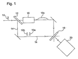
この問題を解決するために、インターフェロメトリを利用することができる。ある技術は、直接的に電界を再構成するスペクトル位相のインターフェロメトリ(SPIDER)であり、この技術を利用する装置は商業的に市販されている。これらの装置を非常に概略的に示した添付図面の図1を参照して、このような従来技術の一例を説明する。周知のレーザ装置を利用して生成された超短パルスが左から入力される。略図では、パルスエンベロープの概略は10で示されている。パルスは、放射(radiation)をパス14へ反射させるエタロン12に衝突し、実際には2の反射光がエタロンの前面および背面から生じ、10aおよび10bで示す、元のパルス10と実質的に同一の2の複製が生成され、一方が他方よりも遅れている。入射パルスの多くは、エタロン12を介して伝搬され、回折格子の分散によりパルスを伸長させるビームストレッチャ16に衝突し、概略的に10cで示される高いチャープパルスが生成される。チャープパルスは、入力パルスの伸長した形態であるのみならず分散でもあり、即ち、放射の長さに沿った異なる部分が、異なる波長、例えば、パルスの前方の長い波長と、パルスの後方の短い波長(または前方の低い周波数と後方の高い周波数)を有する。
To solve this problem, interferometry can be used. One technique is spectral phase interferometry (SPIDER), which directly reconstructs the electric field, and devices utilizing this technique are commercially available. An example of such a prior art will be described with reference to FIG. 1 of the accompanying drawings, which schematically shows these devices. An ultrashort pulse generated using a known laser device is input from the left. In the schematic diagram, the outline of the pulse envelope is indicated by 10. The pulse impinges on the etalon 12, which reflects the radiation to the
パルス10a,10b,および10cは、非線形クリスタル18で組み合わされ、当該クリスタルに入射するパルスの瞬時周波数を合計した放射を生成し、これはまた、アップコンバージョンとして知られている。したがって、第1パルス10aは、パルス10cの準単色部分(スライス)と組み合わされ、チャープパルスの特定領域の周波数でアップコンバートされる元のパルスの複製を生成する。同様に、時間的に遅れたパルス10bは、元のパルスの複製を生成するためにアップコンバートされるが、チャープパルスの別の部分と相互作用するため、アップコンバージョンの周波数偏移は第1パルスと異なる。生成された放射は、分光計20により分析される。
装置はシャーリング干渉計の原理で動作する。複製されたパルス10aおよび10bは、相互に時間的にずれており(shear)、アップコンバージョン後は、チャープパルス10cの別の周波数部分と相互作用するため、相互にスペクトルがずれる。非線形クリスタル18によりアップコンバートした後に分光計20で記録したインターフェログラムは、スペクトルをずらすことにより分離したパルスのスペクトル構成要素間の位相の違いと、時間的なずれによる遅延誘発型のスペクトルの縞を含み、これにより、フーリエ変換に基づくアルゴリズムを利用した入力パルススペクトルの位相の直接的(非反復的)な抽出が可能になる。分光計によるパルススペクトルの振幅の測定に関連するこのスペクトル位相は、完全な測定、すなわち、パルスのスペクトルまたは時間的な電界の特性化を構成する。
The device operates on the principle of a shearing interferometer. The replicated
SPIDER装置に関する更なる情報は、US6,633,386から収集できる。 Further information regarding the SPIDER device can be collected from US 6,633,386.
前述した装置は十分に満足がいくように動作するが、多くの欠点がある。正確に設置する必要がある多くの光学的な構成部品がある。特に、この装置はコンパクトに作ることができない。この装置はチャープパルスを必要とするため、通常、非効率的な回折格子ストレッチャを必要とする。非線形クリスタルは、例えば、数百ミクロン以下のように非常に薄いことが必要があり、これにより、アップコンバージョンの効率をさらに制限する。 Although the apparatus described above works satisfactorily, it has a number of drawbacks. There are many optical components that need to be accurately installed. In particular, this device cannot be made compact. Since this device requires a chirp pulse, it usually requires an inefficient diffraction grating stretcher. Non-linear crystals need to be very thin, for example, a few hundred microns or less, which further limits the efficiency of upconversion.
本発明の目的は、前述した問題のいずれかを少なくとも部分的に解決することである。 The object of the present invention is to at least partially solve any of the problems mentioned above.
したがって本発明は、
測定されるパルスを異なるビームパスに沿って伝搬する2つのサブパルスに分割するスプリッタと、
前記ビームパスに配置された非線形媒体であって、これを通って伝搬する放射をアップコンバージョン可能であり、各サブパルスが、予め定められた角度で前記媒体を通って伝搬するo波成分およびe波成分に分解でき、前記非線形媒体内におけるo波成分とe波成分の相互作用によるアップコンバージョンの位相整合機能により、アップコンバージョンが、予め定められた周波数範囲のo波またはe波の一方の周波数から実質的に独立し、o波とe波のうちの他方の周波数を選択可能である非線形媒体と、
2つのサブパルスが前記非線形媒体内を伝搬することによって得られるアップコンバートされたパルスと干渉する少なくとも一つの構成要素と、
測定されるパルスのスペクトルおよび時間的特性の少なくとも一つを取得するために干渉の結果を検出する検出装置とを具えるパルス測定装置を提供する。
Therefore, the present invention
A splitter that splits the pulse to be measured into two sub-pulses propagating along different beam paths;
An o-wave component and an e-wave component that are arranged in the beam path and are capable of up-converting radiation propagating therethrough, with each subpulse propagating through the medium at a predetermined angle. The up-conversion is substantially performed from one frequency of the o-wave or e-wave in a predetermined frequency range by the phase matching function of the up-conversion by the interaction between the o-wave component and the e-wave component in the nonlinear medium. A non-linear medium capable of selecting the other frequency of the o-wave and e-wave independently,
At least one component interfering with an up-converted pulse obtained by propagating two subpulses in the nonlinear medium;
A pulse measurement device is provided that includes a detection device that detects a result of interference to obtain at least one of a spectrum and temporal characteristics of the pulse being measured.
本発明の更なる態様は、
測定されるパルスを異なるビームパスに沿って伝搬する2つのサブパルスに分割するステップと、
非線形媒体を通って伝搬する放射のアップコンバージョンが可能な非線形媒体を前記ビームパスに配置することにより、スペクトルがずれたサブパルスのアップコンバートされたバージョンを生成するステップであって、各サブパルスが、予め定められた角度で前記媒体を通って伝搬するo波成分およびe波成分に分解でき、前記非線形媒体内におけるo波成分とe波成分の相互作用によるアップコンバージョンの位相整合機能により、アップコンバージョンが、予め定められた周波数範囲にわたりo波またはe波の一方の周波数から実質的に独立しており、o波とe波のうちの他方の周波数を選択可能であるステップと、
2つのサブパルスが前記非線形媒体内を伝搬することによって得られるアップコンバートされたパルスを干渉させるステップと、
測定されるパルスのスペクトルおよび時間的特性の少なくとも一つを取得するために干渉の結果を検出するステップとを具えるパルス測定方法を提供する。
A further aspect of the invention provides:
Splitting the pulse to be measured into two sub-pulses propagating along different beam paths;
Generating an upconverted version of a spectrally shifted subpulse by placing in the beam path a nonlinear medium capable of upconversion of radiation propagating through the nonlinear medium, wherein each subpulse is predetermined. The up-conversion can be decomposed into an o-wave component and an e-wave component propagating through the medium at a given angle, and the up-conversion is performed by the up-conversion phase matching function based on the interaction between the o-wave component and the e-wave component in the nonlinear medium. Being substantially independent of one frequency of the o-wave or e-wave over a predetermined frequency range and being able to select the other frequency of the o-wave and e-wave;
Interfering with an upconverted pulse obtained by two subpulses propagating in the nonlinear medium;
Detecting a result of the interference to obtain at least one of a spectrum and temporal characteristics of the pulse to be measured.
本発明はチャープパルスの必要性を取り除き、これにより光学部品を単純化し、ビームストレッチャを必要としない。単純化された光学部品は、デバイスをよりコンパクトに製造でき、例えば、デバイスの大きさを約15cm×3cm×5cmにすることができる。本発明は、例えば、厚さが2cmの比較的厚い非線形クリスタルを利用する必要があり、これは非常に丈夫で扱い易く、安価で製造でき、デバイスに設置するのが簡単であり寿命が長い。 The present invention eliminates the need for chirp pulses, thereby simplifying the optics and eliminating the need for a beam stretcher. Simplified optical components can make the device more compact, for example, the size of the device can be about 15 cm × 3 cm × 5 cm. The present invention requires the use of, for example, a relatively thick nonlinear crystal with a thickness of 2 cm, which is very strong, easy to handle, inexpensive to manufacture, easy to install in the device and has a long life.
本発明の実施例を非限定的な例示により添付図面を参照してここに説明する。 Embodiments of the present invention will now be described by way of non-limiting illustration and with reference to the accompanying drawings.
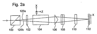
図2および3は、本発明の2の実施例による装置の概略図である。図番の末尾の文字「a」および「b」はそれぞれ、同一の装置の平面図および側面図を示している。もちろん、「平面」および「側面」の語は、純粋に任意であり、装置が特定の方向で動作しなければならないことを意味するものではない。図2および3では、同様の部品は、同様の参照番号で示されている。第1の装置(図2aおよび2b)は、順に以下の構成部品、
偏光ビームスプリッタ100と、2分の1波長板(λ/2板)102と、非線形媒体のクリスタル104と、フレネル複プリズム106と、波長分散プリズム108と、クリスタルレンズ110と、電荷結合素子(CCD)カメラチップなどの検出器アレイ112とからなる。
2 and 3 are schematic views of an apparatus according to two embodiments of the present invention. Letters “a” and “b” at the end of the figure numbers respectively indicate a plan view and a side view of the same apparatus. Of course, the terms “plane” and “side” are purely arbitrary and do not imply that the device must operate in a particular direction. 2 and 3, like parts are indicated with like reference numerals. The first device (FIGS. 2a and 2b) in turn comprises the following components:
第2の装置(図3aおよび3b)では、偏光ビームスプリッタが、スプリッタを構成する僅かに傾斜した隣接する2の鏡114と、平面鏡116に置き換えられている。ここで使われている「鏡」の語は、問題になっている放射に適した任意の反射鏡要素または面を意味する。
In the second device (FIGS. 3a and 3b), the polarizing beam splitter has been replaced by two slightly inclined
図2,3および4を参照する2の実施例の説明では、以下の取り決めが採用される、即ち、放射の伝搬方向をZ方向とし、X方向は、図2a,3a,および4では紙面上であり(図2bおよび3bでは紙面に対して垂直であり)、Y方向は、図2a,3a,および4では紙面に対して垂直である(図2bおよび3bでは紙面上である)。 In the description of the second embodiment with reference to FIGS. 2, 3 and 4, the following convention is adopted: the direction of propagation of radiation is the Z direction, and the X direction is on paper in FIGS. 2a, 3a and 4 (They are perpendicular to the page in FIGS. 2b and 3b) and the Y direction is perpendicular to the page in FIGS. 2a, 3a and 4 (on the page in FIGS. 2b and 3b).
測定する必要がある超短パルスは、図2aおよび2bに示す装置に左側から入る。偏光ビームスプリッタ100は、このパルスをビームパス120aおよび120bに沿って伝搬する2の複製またはサブパルスに分割し、これらの伝搬方向は、小さな角をなして互いに離れている。この2つのサブパルスは、相互に直交し直線的に偏光し、一方はX方向に他方はY方向に偏光する。図示されている実施例では、ウラストンプリズムが偏光ビームスプリッタ100として利用されるが、代替的に薄いフィルム型の偏光ビームスプリッタを利用してもよい。ウラストンプリズムは特に、70フェムト秒よりも長い継続時間のパルスに好適である。70フェムト秒よりも短いパルスの場合、ウラストンプリズムは、隣接する2の鏡114と置き換えられる(図3aおよび3bを参照)。これらの2の鏡が僅かに傾斜していることにより、パルスが分割されて2の複製が生じる。平面鏡116は2のビームを受け、これらを非線形クリスタル104に送る。図2および3に示す2の装置の残りの部品は互いに同一である。
The ultrashort pulse that needs to be measured enters the device shown in FIGS. 2a and 2b from the left.
2の複製されたサブパルスは、2分の1波長板102に入射される。通常、2のビームパスの間の角度は非常に小さく、例えば2度よりも小さく、2のビームパスはそれぞれ、2分の1波長板にほぼ垂直に入射する。2分の1波長板は、動作中は十分に広帯域であり、これは、入射パルスの異なる波長(周波数)構成要素のために機能し、パルスの継続時間に依存する。2分の1波長板は、ゼロ次波長板であることが好ましい。2分の1波長板はXY平面上に配置されるが、2分の1波長板の光学軸は、Z軸を中心に回転するため、XまたはY方向に沿って配置されない。2分の1波長板の光学軸は、XまたはY軸のいずれかから22.5°傾斜していることが好適である。これは、ビーム120a,120bに沿った一方のパルスの偏光面が、Z軸を中心に45°回転し、他のパルスの偏光面がZ軸を中心に135°回転する効果がある。この結果、2分の1波長板102から発生するパルスは、相互に直交し直線的に偏光するが、XまたはY軸のいずれかに対して45°で偏光する(パルスは、XZ平面上で互いに分岐する)。もちろん、45°の他に別の他の角度を用いることができ、角度の精密な選択は、特定の非線形クリスタルに基づいて最適化できるが、発生した各パルスは、X軸に平行な構成要素とY軸に平行な構成要素に分割可能な偏光を有することが必要である。これは、次に説明する非線形クリスタル104における混合および和周波数発生に必要である。
Two replicated subpulses are incident on the half-
図4の120で示す2のパルスビームパス120aまたは120bの一方または他方を考えると、図4は、非線形クリスタル104に関する配置をより詳細に示している。非線形クリスタル104の光学軸は、XZ平面上にある破線の矢印cで示されている。入射放射はZ方向に伝搬する。クリスタル104は、放射がほぼ直角に入射してクリスタルの表面から現れ、伝搬の方向、即ちZ方向がクリスタル材の光学軸Cに対して特定の角度θを形成するようにカットされている。入射放射は、例えば、XおよびY軸に対して45°の方向に偏光される。この放射はクリスタル104内で、c軸に対して垂直に偏光した(即ちY方向の)o波成分と、o光線に対して垂直に偏光した(即ちX方向の)e波成分に分割される。非線形クリスタルは単軸および複屈折であり、このため、o波およびe波(定常波および異常波)は有効屈折率が異なり、異なる速度で伝搬する。o波およびe波は、実質的に独立した同一線上の伝搬波を構成する。適切な位相整合条件下では、o波パルスおよびe波パルスの相互作用は、和周波数発生(SFG)として知られている入力パルスの周波数を合計してアップコンバートしたパルスを生成することができる。生成されたアップコンバートパルスは、e波に平行に偏光され、図4でSFGとして示されている。
Considering one or the other of the two
非線形クリスタル104の素材および角度θは、非常に特殊な位相整合機能(PMF)を提供するために選択され、特定の波長範囲の入射放射をアップコンバートする。PMFはほぼ垂直(即ち、急傾斜)であり、実質的にo軸に沿って非常に広範囲であり、e軸に沿って非常に狭い。このような非対称のPMF形状は、o−基本入力(fundamental input)とe−アップコンバートされた出力フィールドとの間の一群の速度整合と、o−基本入力とe−基本入力フィールドとの間の一群の速度不整合によるものである。
The material of the
図5を参照すると、角度θの異なる値に関するPMFの振幅の重ね合わされた2の輪郭のプロットが示されている。e波パルスの波長は水平に描かれ、o波パルスの波長は垂直に描かれている。暗い範囲は、同一線上を伝搬するoおよびe波が混合する傾向が低いこと示しており、明るい範囲は、混合して和周波数を生成する傾向が高いことを示している。放射が角度θ1で伝搬する場合、混合は、約831nmの波長のe波の狭い部分に非常に特有であるが、混合はo波の広範な波長に亘って発生する。異なる角度θ2で伝搬する同一線上のパルスの場合も同様であるが、この場合o波の混合は、別のe波の波長のときに発生する。超短パルスが約830nmを中心とする場合、図5のPMFの特異な形状により、o波の帯域幅全体が、e波のスペクトルの準単色部分と混合可能である。クリスタルの回転を利用することにより、和周波数生成(SFG)の波長の中心を調整できる。 Referring to FIG. 5, a plot of two superimposed contours of PMF amplitude for different values of angle θ is shown. The wavelength of the e-wave pulse is drawn horizontally, and the wavelength of the o-wave pulse is drawn vertically. The dark range indicates a low tendency to mix o and e waves propagating on the same line, and the bright range indicates a high tendency to mix and generate a sum frequency. If the radiation propagates at an angle θ 1 , the mixing is very specific to the narrow part of the e-wave with a wavelength of about 831 nm, but the mixing occurs over a wide range of o-wave wavelengths. The same applies to pulses on the same line propagating at different angles θ 2 , but in this case o-wave mixing occurs at different e-wave wavelengths. If the ultrashort pulse is centered around 830 nm, the unique shape of the PMF in FIG. 5 allows the entire bandwidth of the o-wave to be mixed with the quasi-monochromatic portion of the e-wave spectrum. By utilizing the rotation of the crystal, the center of the wavelength of sum frequency generation (SFG) can be adjusted.
この具体例では、非線形クリスタルは、長さが約2cmであり、KDP(リン酸二水素カリウム)から形成される。これは、角度θが約68°になるようにカットされ、フリースペースの波長が830nmの範囲にある状態で、放射のアップコンバージョンを最大にする。図2a(3a)の2のビームパス120aおよび120bに沿って伝わるパルスは、図5で参照される角度θ1およびθ2で伝搬し、前述した角度θからそれぞれ約+および−0.125°異なり、即ち、互いに約0.25°異なる。
In this specific example, the non-linear crystal is about 2 cm in length and is formed from KDP (potassium dihydrogen phosphate). This is cut so that the angle θ is about 68 ° and maximizes the radiation up-conversion with the free space wavelength in the range of 830 nm. The pulses traveling along the two
したがって、角度θ1で伝搬する一方のパルスのo−成分のスペクトル全体は、831nmの波長に対応する周波数でアップコンバートされ、角度θ2で伝搬する他方のパルスのo−成分のスペクトル全体は、約829nmの放射の周波数に対応する別の量でアップコンバートされる。特殊な位相整合機能により、アップコンバージョンは、周波数選択性が高くなり、o波パルススペクトルがアップコンバートされる特定の周波数は、伝搬角に依存する。これにより、入力パルスの複製である2の和周波数パルスが発生するが、これらは異なる周波数でアップコンバートされ、相互にスペクトルがずれる。 Thus, the entire spectrum of the o-component of one pulse propagating at an angle θ 1 is upconverted at a frequency corresponding to a wavelength of 831 nm, and the entire spectrum of the o-component of the other pulse propagating at an angle θ 2 is Upconverted by another amount corresponding to a frequency of radiation of about 829 nm. Due to the special phase matching function, upconversion is highly frequency selective and the specific frequency at which the o-wave pulse spectrum is upconverted depends on the propagation angle. This generates two sum frequency pulses that are duplicates of the input pulse, but they are upconverted at different frequencies and are out of spectrum with each other.
図5は、PMFの振幅を示している。この特殊で非対称的なPMFは、o−基本入力とeアップコンバートされた出力フィールドとの間の一群の速度整合と、o−基本とe−基本入力フィールドとの間の多数群の速度不整合の結果である。o−基本入力からe−アップコンバートされた出力フィールドへの完全な波形変換を得るために、即ち、アップコンバートされた元のパルスの複製を提供するために、e−基本パルスが、非線形クリスタル内を伝搬する間、完全にo−基本パルスを介して進まなければならない。この必要を満たすべく、本発明のこの実施例では、初めに、o−波およびe−波成分を、分かっていないパルス総てを含む時間枠とほぼ等しい遅延時間分互いに対して事前に遅らせる必要がある。次に、クリスタルの長さは、伝搬速度が異なるため、少なくともウォークオフタイムの2倍と同一でなければならなず、先の時間枠の継続時間により分割される。KDPの場合、e波は、o波に対して事前に遅延させなければならず、ウォークオフタイムは、素材の1cmあたり約1.5ピコ秒である。事前の遅延は、相互に直交し直線的に偏光された構成要素を遅らせる(直交し直線的に偏光された構成要素は、非線形クリスタル内のe波およびo波になる)、非線形クリスタルに先行する光学的構成要素により実現する。ビームスプリッタ100のような好適なウラストンプリズムが、本質的に遅延を提供する。代替的に、好適な追加の複屈折媒体または波長板を利用してもよい。
FIG. 5 shows the amplitude of the PMF. This special asymmetric PMF consists of a group of velocity matches between the o-base input and the e-upconverted output field, and a group of velocity mismatches between the o-base and the e-base input field. Is the result of In order to obtain a complete waveform conversion from the o-primary input to the e-upconverted output field, i.e. to provide a copy of the original upconverted pulse, the e-basic pulse is included in the nonlinear crystal. Must travel completely through the o-basic pulse. In order to meet this need, in this embodiment of the invention, the o-wave and e-wave components must first be pre-delayed with respect to each other by a delay time approximately equal to the time frame containing all the unknown pulses. There is. Next, the length of the crystal must be at least equal to twice the walk-off time due to different propagation speeds, and is divided by the duration of the previous time frame. In the case of KDP, the e-wave must be delayed in advance with respect to the o-wave, and the walk-off time is about 1.5 picoseconds per cm of material. Pre-delay precedes the nonlinear crystal, delaying mutually orthogonal and linearly polarized components (orthogonal and linearly polarized components become e and o waves in the nonlinear crystal) Realized by optical components. A suitable Wollaston prism, such as
アップコンバージョン処理は、e−基本とo−基本フィールドとの間の一群の速度不整合が存在する限り、o−基本とeアップコンバートされたフィールドとの間の速度整合群の基準を満たさない波長で利用することもできる。このような場合、アップコンバートされた出力フィールドは、O−基本入力パルスを伸長した複製である。伸長要素は、依存性素材であり、反対の伸長要素を利用して、元のパルスに関する所望の情報を再生することができる。これにより、PMFの要求を満たす波長を中心としたスペクトル領域への装置の適用性を広げることができる。 The up-conversion process does not satisfy the velocity matching group criteria between the o-basic and e-upconverted fields as long as there is a group of velocity mismatches between the e-basic and o-basic fields. Can also be used. In such a case, the upconverted output field is a duplicated version of the O-basic input pulse. The stretch element is a dependent material and the opposite stretch element can be used to reconstruct the desired information about the original pulse. Thereby, the applicability of the apparatus to the spectral region centered on the wavelength satisfying the requirement of PMF can be expanded.
非線形クリスタル素材の他の種類もまた、前述したPMFの要求を別の波長範囲において満たすことができる。例えば、KDPについて前述した退化した(degenerate)同一線上のタイプIIアレイの場合、共通の非線形の単軸クリスタルの非線型光学結晶(BBO)は、1.17μmおよび1.95μmのスペクトル範囲を中心とするパルスに適用でき、重水素置換燐酸二水素カリウム(KD*P)は、0.95μmおよび1.83μmのスペクトル範囲を中心とするパルスに適用できる。追加のクリスタルの例および計算結果は、Eliminating Frequency and Space-time Correlations in Multiphoton state, W.P.Grice, A.B.U'Ren and I.A. Walmsley, Physical Review A, vol.64, 2001にある。非線形タイプIの相互作用も実現できる(Sub-5 fs Pulse Generation from a Noncollinear Optical Parametric Amplifier, T.Kobayashi, A.Baltushka, Measurement Science nad Technology, vol.13, pg.1671, 2002とここに記載されている参考資料を参照)。2軸のクリスタルも利用でき、さらに、適用可能なスペクトル範囲のセットを拡張する。例えば、硼酸リチウム(LBO)は、0.91μm、0.98μm、および1.77μmのスペクトル範囲を中心とするパルスに適用できる。 Other types of non-linear crystal materials can also meet the PMF requirements described above in other wavelength ranges. For example, in the case of the degenerate collinear Type II array described above for KDP, the common nonlinear uniaxial crystal nonlinear optical crystal (BBO) is centered around the 1.17 μm and 1.95 μm spectral ranges. Deuterium-substituted potassium dihydrogen phosphate (KD * P) can be applied to pulses centered in the 0.95 μm and 1.83 μm spectral ranges. Examples of additional crystals and calculation results can be found in Eliminating Frequency and Space-time Correlations in Multiphoton state, WPGrice, ABU'Ren and IA Walmsley, Physical Review A, vol. 64, 2001. Non-linear type I interactions can also be realized (sub-5 fs Pulse Generation from a Noncollinear Optical Parametric Amplifier, T. Kobayashi, A. Baltushka, Measurement Science nad Technology, vol. 13, pg. 1671, 2002. See reference material). Two-axis crystals are also available, further extending the set of applicable spectral ranges. For example, lithium borate (LBO) can be applied to pulses centered at 0.91 μm, 0.98 μm, and 1.77 μm spectral ranges.
これにより、スペクトルのずれを実現し、2の和周波数パルスは、角度θ1とθ2との違いにより分離する別の方向で伝搬し、この角度の分離は、別の遅延時間に対応するパスの長さが異なるため、時間的なずれの範囲を提供する。図2および3の残りの構成部品は本質的に、2次元画像分光計を構成する。フレネル複プリズム106は、2の分岐するパルスビームをCCD検出器アレイ112に集中させ、干渉縞を提供することができる。分散プリズム108は、ずれたパルスの別のスペクトル構成要素を角度を付けて分散し、円筒形レンズ110は、これをCCDアレイ112上で空間的に分離する。分光計の他の構成を利用してもよい。
This realizes a spectral shift, and the two sum frequency pulses propagate in different directions that separate due to the difference between the angles θ 1 and θ 2, and this angular separation is a path corresponding to another delay time. Since the lengths of these are different, they provide a range of time lag. The remaining components of FIGS. 2 and 3 essentially constitute a two-dimensional image spectrometer. The
図2bおよび3bでは、CCDアレイ112の一列の各ピクセルは、干渉するスペクトルがずれたパルスの別の波長λ(または周波数)部分(スライス)に対応する。図2aおよび3aに示すように、2のアップコンバートされたパルスは、相互に傾斜した波面を有し、これらがCCDアレイ112で干渉するときに縞模様を生じさせ、CCD検出器アレイ112の一行の各ピクセルは、2のパルスの間の別のパス長の違いに対応し、即ち、別の時間的なずれは、空間的な干渉縞に変換される。結果として生じる空間スペクトルの干渉縞のフーリエ処理は、元のパルスに関する所望の位相情報を生む。周知の処理技術を用いて、ビーム内の空間的な各位置におけるフィールドの時間依存性と、同じ位置におけるパルススペクトルの測定値を抽出することができる。検出器アレイの信号から入力パルスの所望の特性を取得することに関する更なる情報は、例えば、Iaconis and I A Walmsley, IEEE Journal of Quantum Electronics, vol.35, no.4, April 1999のSelf-referencing Spectral Interferometry for Measuring Ultra Short Optical Pulsesから入手できる。
In FIGS. 2b and 3b, each column of pixels in the
したがって、本発明の所望の装置および方法を利用することにより、伸長したパルスの複製を使用することなく、パルスのスペクトルまたは時間的な電界の測定結果を完全に取得することができる。 Thus, by utilizing the desired apparatus and method of the present invention, it is possible to obtain a complete spectrum of pulse or temporal electric field measurements without using stretched pulse replicas.
Claims (18)
測定されるパルスを異なるビームパスに沿って伝播する2つのサブパルスに分割するスプリッタと;
前記ビームパスに配置された非線形複屈折媒体であって、各サブパルスを、各々のサブパルスの入射ビームパスに対し角度(θ)で前記媒体を通って伝搬するo波成分およびe波成分に分解する非線形複屈折媒体を具えるパルス測定装置において:
前記媒体が、o波およびe波の一方を備える第1の波の基本周波数とo波およびe波の他方を備える第2の波のアップコンバートされた周波数との間の群速度が適合するよう選択された角度(θ)を有するアップコンバート媒体であり、アップコンバージョンのための位相整合機能が、第1の波の周波数から独立しており、第2の波のために選択された周波数であり;
前記2つのサブパルスが前記非線形媒体内を伝搬することによって得られるアップコンバートされたパルスを干渉する少なくとも一つの構成要素と;
測定されるパルスのスペクトルおよび時間的特性の少なくとも一つを取得するために干渉の結果を検出する検出装置と;を具えることを特徴とするパルス測定装置。 A pulse measuring device;
A splitter that splits the pulse to be measured into two sub-pulses propagating along different beam paths;
A nonlinear birefringent medium disposed in the beam path, wherein each subpulse is decomposed into an o-wave component and an e-wave component propagating through the medium at an angle (θ) with respect to the incident beam path of each subpulse. In a pulse measuring device comprising a refractive medium:
The medium matches a group velocity between a fundamental frequency of a first wave comprising one of o and e waves and an upconverted frequency of a second wave comprising the other of o and e waves. An up-conversion medium with a selected angle (θ), wherein the phase matching function for up-conversion is independent of the frequency of the first wave and is the frequency selected for the second wave ;
At least one component interfering with the upconverted pulse obtained by the two subpulses propagating in the nonlinear medium;
And a detector for detecting the result of interference to obtain at least one of a spectrum and temporal characteristics of the pulse to be measured.
測定されるパルスを異なるビームパスに沿って伝搬する2つのサブパルスに分割するステップと;
前記ビームパスに非線形複屈折媒体を配置するステップであって、非線形複屈折媒体が、各々のサブパルスの入射ビームパスに対し角度(θ)で前記媒体を通って伝搬するo波成分およびe波成分に分解するステップと;を具えるパルス測定方法において:
o波およびe波の一方を備える第1の波の基本周波数とo波およびe波の他方を備える第2の波のアップコンバートされた周波数との間の群速度が適合するよう角度(θ)を選択するステップであって、アップコンバージョンのための位相整合機能が、第1の波の周波数から独立しており、第2の波のために選択された周波数であるステップと;
前記2つのサブパルスが前記非線形媒体内を伝搬することによって得られるアップコンバートされたパルスを干渉させるステップと;
測定されるパルスのスペクトルおよび時間的特性の少なくとも一つを取得するために干渉の結果を検出するステップと;を具えることを特徴とするパルス測定方法。
A pulse measurement method;
Splitting the pulse to be measured into two sub-pulses propagating along different beam paths;
Placing a nonlinear birefringent medium in the beam path, wherein the nonlinear birefringent medium is decomposed into an o-wave component and an e-wave component propagating through the medium at an angle (θ) with respect to an incident beam path of each subpulse. In a pulse measurement method comprising:
an angle (θ) such that the group velocity between the fundamental frequency of the first wave comprising one of the o and e waves and the upconverted frequency of the second wave comprising the other of the o and e waves is matched A phase matching function for upconversion is independent of the frequency of the first wave and is the frequency selected for the second wave;
Interfering with the up-converted pulse obtained by the two sub-pulses propagating in the nonlinear medium;
Detecting a result of interference to obtain at least one of a spectrum and a temporal characteristic of the pulse to be measured.
Applications Claiming Priority (3)
| Application Number | Priority Date | Filing Date | Title |
|---|---|---|---|
| GBGB0510338.7A GB0510338D0 (en) | 2005-05-20 | 2005-05-20 | Electromagnetic radiation pulse measurement apparatus and method |
| GB0510338.7 | 2005-05-20 | ||
| PCT/GB2006/001823 WO2006123148A1 (en) | 2005-05-20 | 2006-05-18 | Ultra-short optical pulse measurement using a thick nonlinear crystal |
Publications (2)
| Publication Number | Publication Date |
|---|---|
| JP2008541124A JP2008541124A (en) | 2008-11-20 |
| JP5265351B2 true JP5265351B2 (en) | 2013-08-14 |
Family
ID=34834388
Family Applications (1)
| Application Number | Title | Priority Date | Filing Date |
|---|---|---|---|
| JP2008511789A Expired - Fee Related JP5265351B2 (en) | 2005-05-20 | 2006-05-18 | Measurement of ultrashort light pulses using thick nonlinear crystals. |
Country Status (6)
| Country | Link |
|---|---|
| US (1) | US7599067B2 (en) |
| EP (1) | EP1886107B1 (en) |
| JP (1) | JP5265351B2 (en) |
| AT (1) | ATE539331T1 (en) |
| GB (1) | GB0510338D0 (en) |
| WO (1) | WO2006123148A1 (en) |
Families Citing this family (14)
| Publication number | Priority date | Publication date | Assignee | Title |
|---|---|---|---|---|
| FR2925956B1 (en) * | 2007-12-26 | 2010-01-15 | Fastlite | METHOD AND DEVICE FOR MEASURING THE SPECTRAL PHASE OR COMBINED SPECTRA AND SPACE PHASES OF ULTRA BRIEF LUMINOUS PULSES. |
| US9347832B2 (en) * | 2008-05-15 | 2016-05-24 | Bodkin Design And Engineering Llc | Optical systems and methods employing a polarimetric optical filter |
| WO2013152781A1 (en) * | 2012-04-11 | 2013-10-17 | Gottfried Wilhelm Leibniz Universität Hannover | Arrangement for measuring laser pulses |
| JP6053138B2 (en) * | 2013-01-24 | 2016-12-27 | 株式会社日立エルジーデータストレージ | Optical tomographic observation apparatus and optical tomographic observation method |
| CN103234979B (en) * | 2013-04-07 | 2015-09-09 | 北京大恒图像视觉有限公司 | Vial defect detecting device and point picture device |
| CN103278249A (en) * | 2013-05-15 | 2013-09-04 | 中国科学院上海光学精密机械研究所 | Quasi-near field picosecond pulse width diagnosis instrument |
| WO2016152108A1 (en) * | 2015-03-25 | 2016-09-29 | 日本電気株式会社 | Light measurement device |
| US10921448B2 (en) * | 2015-09-18 | 2021-02-16 | Hamamatsu Photonics K.K. | Optical distance measuring system |
| EP3497416B1 (en) * | 2016-08-10 | 2022-07-13 | Sphere Ultrafast Photonics, S.A. | Ultrashort laser pulse characterization method and system |
| CN106444346B (en) * | 2016-10-31 | 2018-12-14 | 中国科学院西安光学精密机械研究所 | A kind of sub- femtosecond time resolution streak camera of Terahertz driving |
| ES2680045B1 (en) * | 2017-02-20 | 2019-07-02 | Univ Salamanca | APPARATUS AND METHOD OF MEASUREMENT IN LINE OF LASER PULSES WITH POLARIZATION DEPENDENT ON TIME |
| CN107063476B (en) * | 2017-05-27 | 2019-05-17 | 中国电子科技集团公司第四十一研究所 | A kind of device and method measuring Terahertz wavelength |
| CN112326029A (en) * | 2020-10-19 | 2021-02-05 | 南京航空航天大学 | Novel ultrafast real-time spectrum analyzer |
| CN112595425B (en) * | 2020-12-03 | 2021-12-03 | 华中科技大学 | Ultrashort laser pulse measuring method and measuring system |
Family Cites Families (7)
| Publication number | Priority date | Publication date | Assignee | Title |
|---|---|---|---|---|
| DE69835090T2 (en) * | 1997-08-01 | 2007-01-18 | The University Of Rochester | IMPULSE MEASUREMENTS BY FREQUENCY SHIFTING TECHNIQUES |
| JPH11326066A (en) * | 1998-05-18 | 1999-11-26 | Teratec:Kk | Light sampling wave-form observing device and method |
| JP2001125155A (en) * | 1999-10-22 | 2001-05-11 | Chubu Electric Power Co Inc | Wavelength conversion element |
| US6504612B2 (en) * | 2000-11-14 | 2003-01-07 | Georgia Tech Research Corporation | Electromagnetic wave analyzer |
| EP1417449A1 (en) * | 2001-07-23 | 2004-05-12 | University of Rochester | Optical pulse measurement |
| DE10143709A1 (en) * | 2001-08-31 | 2003-04-03 | Jenoptik Laser Optik Sys Gmbh | Device for frequency conversion of a basic laser frequency into other frequencies |
| US7570851B2 (en) * | 2004-07-21 | 2009-08-04 | Purdue Research Foundation | Ultrashort photonic waveform measurement using quasi-phase-matched non-linear optics |
-
2005
- 2005-05-20 GB GBGB0510338.7A patent/GB0510338D0/en not_active Ceased
-
2006
- 2006-05-18 EP EP06743921A patent/EP1886107B1/en active Active
- 2006-05-18 WO PCT/GB2006/001823 patent/WO2006123148A1/en not_active Application Discontinuation
- 2006-05-18 AT AT06743921T patent/ATE539331T1/en active
- 2006-05-18 US US11/914,888 patent/US7599067B2/en active Active
- 2006-05-18 JP JP2008511789A patent/JP5265351B2/en not_active Expired - Fee Related
Also Published As
| Publication number | Publication date |
|---|---|
| US20080212103A1 (en) | 2008-09-04 |
| WO2006123148A1 (en) | 2006-11-23 |
| ATE539331T1 (en) | 2012-01-15 |
| JP2008541124A (en) | 2008-11-20 |
| EP1886107A1 (en) | 2008-02-13 |
| GB0510338D0 (en) | 2005-06-29 |
| EP1886107B1 (en) | 2011-12-28 |
| US7599067B2 (en) | 2009-10-06 |
Similar Documents
| Publication | Publication Date | Title |
|---|---|---|
| JP5265351B2 (en) | Measurement of ultrashort light pulses using thick nonlinear crystals. | |
| Tikan et al. | Single-shot measurement of phase and amplitude by using a heterodyne time-lens system and ultrafast digital time-holography | |
| Teo et al. | Invited Article: Single-shot THz detection techniques optimized for multidimensional THz spectroscopy | |
| Réhault et al. | Two-dimensional electronic spectroscopy with birefringent wedges | |
| US6504612B2 (en) | Electromagnetic wave analyzer | |
| Brixner et al. | Phase-stabilized two-dimensional electronic spectroscopy | |
| Tran | Acousto-Optic Devices | |
| Tekavec et al. | Wave packet interferometry and quantum state reconstruction by acousto-optic phase modulation | |
| JP6654948B2 (en) | Method and apparatus for measuring pulse light waveform | |
| Potenza et al. | Three dimensional imaging of short pulses | |
| US6204926B1 (en) | Methods and system for optically correlating ultrashort optical waveforms | |
| EP0243130B1 (en) | Phase conjugate reflecting media | |
| Wang et al. | Temporal and chirp effects of laser pulses on the spectral line shape in sum-frequency generation vibrational spectroscopy | |
| Zhai et al. | Time-resolved single-shot terahertz time-domain spectroscopy for ultrafast irreversible processes | |
| Nuernberger et al. | Polarization-shaped femtosecond laser pulses in the ultraviolet | |
| JP3533651B1 (en) | Time-resolved nonlinear susceptibility measurement system | |
| Wang et al. | Effect of visible pulse shaping on the accuracy of relative intensity measurements in BBSFG vibrational spectroscopy | |
| Lin et al. | Single-shot measurement of temporally-dependent polarization state of femtosecond pulses by angle-multiplexed spectral-spatial interferometry | |
| Lelek et al. | Time resolved spectral interferometry for single shot femtosecond characterization | |
| Hedegaard Kristensen et al. | Terahertz generation through optical rectification in reflection | |
| CN107923798B (en) | Autocorrelation measuring device | |
| Bai et al. | Generation of double pulses in-line by using reflective Dammann gratings | |
| Kristensen et al. | Fourier transform second harmonic generation for high-resolution nonlinear spectroscopy | |
| JP2723201B2 (en) | Optical response speed measuring instrument | |
| Szmygel et al. | Characterizing ultrashort laser pulses by the rotational Doppler effect |
Legal Events
| Date | Code | Title | Description |
|---|---|---|---|
| A621 | Written request for application examination |
Free format text: JAPANESE INTERMEDIATE CODE: A621 Effective date: 20090325 |
|
| A977 | Report on retrieval |
Free format text: JAPANESE INTERMEDIATE CODE: A971007 Effective date: 20110616 |
|
| A131 | Notification of reasons for refusal |
Free format text: JAPANESE INTERMEDIATE CODE: A131 Effective date: 20110726 |
|
| A601 | Written request for extension of time |
Free format text: JAPANESE INTERMEDIATE CODE: A601 Effective date: 20111026 |
|
| A602 | Written permission of extension of time |
Free format text: JAPANESE INTERMEDIATE CODE: A602 Effective date: 20111102 |
|
| A601 | Written request for extension of time |
Free format text: JAPANESE INTERMEDIATE CODE: A601 Effective date: 20111125 |
|
| A602 | Written permission of extension of time |
Free format text: JAPANESE INTERMEDIATE CODE: A602 Effective date: 20111202 |
|
| A521 | Request for written amendment filed |
Free format text: JAPANESE INTERMEDIATE CODE: A523 Effective date: 20111226 |
|
| A131 | Notification of reasons for refusal |
Free format text: JAPANESE INTERMEDIATE CODE: A131 Effective date: 20120605 |
|
| TRDD | Decision of grant or rejection written | ||
| A01 | Written decision to grant a patent or to grant a registration (utility model) |
Free format text: JAPANESE INTERMEDIATE CODE: A01 Effective date: 20130402 |
|
| A61 | First payment of annual fees (during grant procedure) |
Free format text: JAPANESE INTERMEDIATE CODE: A61 Effective date: 20130501 |
|
| R150 | Certificate of patent or registration of utility model |
Free format text: JAPANESE INTERMEDIATE CODE: R150 Ref document number: 5265351 Country of ref document: JP Free format text: JAPANESE INTERMEDIATE CODE: R150 |
|
| R250 | Receipt of annual fees |
Free format text: JAPANESE INTERMEDIATE CODE: R250 |
|
| S531 | Written request for registration of change of domicile |
Free format text: JAPANESE INTERMEDIATE CODE: R313531 |
|
| S533 | Written request for registration of change of name |
Free format text: JAPANESE INTERMEDIATE CODE: R313533 |
|
| R350 | Written notification of registration of transfer |
Free format text: JAPANESE INTERMEDIATE CODE: R350 |
|
| R250 | Receipt of annual fees |
Free format text: JAPANESE INTERMEDIATE CODE: R250 |
|
| R250 | Receipt of annual fees |
Free format text: JAPANESE INTERMEDIATE CODE: R250 |
|
| R250 | Receipt of annual fees |
Free format text: JAPANESE INTERMEDIATE CODE: R250 |
|
| R250 | Receipt of annual fees |
Free format text: JAPANESE INTERMEDIATE CODE: R250 |
|
| R250 | Receipt of annual fees |
Free format text: JAPANESE INTERMEDIATE CODE: R250 |
|
| R250 | Receipt of annual fees |
Free format text: JAPANESE INTERMEDIATE CODE: R250 |
|
| LAPS | Cancellation because of no payment of annual fees |