JP5265012B2 - Electronics - Google Patents
Electronics Download PDFInfo
- Publication number
- JP5265012B2 JP5265012B2 JP2011528594A JP2011528594A JP5265012B2 JP 5265012 B2 JP5265012 B2 JP 5265012B2 JP 2011528594 A JP2011528594 A JP 2011528594A JP 2011528594 A JP2011528594 A JP 2011528594A JP 5265012 B2 JP5265012 B2 JP 5265012B2
- Authority
- JP
- Japan
- Prior art keywords
- electronic component
- hdd
- vent
- hard disk
- fan
- Prior art date
- Legal status (The legal status is an assumption and is not a legal conclusion. Google has not performed a legal analysis and makes no representation as to the accuracy of the status listed.)
- Expired - Fee Related
Links
Images


Classifications
-
- G—PHYSICS
- G06—COMPUTING; CALCULATING OR COUNTING
- G06F—ELECTRIC DIGITAL DATA PROCESSING
- G06F1/00—Details not covered by groups G06F3/00 - G06F13/00 and G06F21/00
- G06F1/16—Constructional details or arrangements
- G06F1/20—Cooling means
- G06F1/203—Cooling means for portable computers, e.g. for laptops
-
- G—PHYSICS
- G06—COMPUTING; CALCULATING OR COUNTING
- G06F—ELECTRIC DIGITAL DATA PROCESSING
- G06F1/00—Details not covered by groups G06F3/00 - G06F13/00 and G06F21/00
- G06F1/16—Constructional details or arrangements
- G06F1/1613—Constructional details or arrangements for portable computers
- G06F1/1633—Constructional details or arrangements of portable computers not specific to the type of enclosures covered by groups G06F1/1615 - G06F1/1626
- G06F1/1656—Details related to functional adaptations of the enclosure, e.g. to provide protection against EMI, shock, water, or to host detachable peripherals like a mouse or removable expansions units like PCMCIA cards, or to provide access to internal components for maintenance or to removable storage supports like CDs or DVDs, or to mechanically mount accessories
- G06F1/1658—Details related to functional adaptations of the enclosure, e.g. to provide protection against EMI, shock, water, or to host detachable peripherals like a mouse or removable expansions units like PCMCIA cards, or to provide access to internal components for maintenance or to removable storage supports like CDs or DVDs, or to mechanically mount accessories related to the mounting of internal components, e.g. disc drive or any other functional module
Description
本件は、例えばノート型パーソナルコンピュータ(以下、「ノートPC」と略記する)等の電子機器に関する。 This case relates to an electronic device such as a notebook personal computer (hereinafter abbreviated as “notebook PC”).
ノートPC等の電子機器は、小型化等の要請から、多数の電子部品が筐体内にほとんど隙き間もない程に密に収納されている。ここで、ノートPCには、通常、ハードディスクドライブ(以下、「HDD」と略記する)が内蔵されている。このHDDは、円盤状のハードディスクをモータで回転させながらそのハードディスク上に情報を磁気的に記録し、あるいはハードディスク上に磁気的に記録された情報を読み出す電子部品である。HDDはモータを内蔵していることからそのモータが発熱し、これを冷却することが求められる。ノートPCの筐体には、HDD以外にもCPUチップ等の発熱電子部品が存在し発熱部品冷却のためのファンが内蔵されている。このファンによる空気流を利用すればHDDも冷却することができる。しかしながら、筐体内には多数の電子部品が密に収納されており、HDDに直ぐ隣接して面積の広いプリント配線基板(メインボード)が配置されているようなレイアウトの場合、HDDに沿って流れる十分な空気流を確保するだけの隙き間を確保するのが困難である。 2. Description of the Related Art Electronic devices such as notebook PCs are housed in such a manner that a large number of electronic components are tightly accommodated in a housing due to demands for downsizing and the like. Here, the notebook PC usually has a built-in hard disk drive (hereinafter abbreviated as “HDD”). The HDD is an electronic component that magnetically records information on a hard disk while rotating the disk-shaped hard disk with a motor, or reads information magnetically recorded on the hard disk. Since the HDD has a built-in motor, the motor generates heat and is required to be cooled. In addition to the HDD, the notebook PC has heat generating electronic components such as a CPU chip and a fan for cooling the heat generating components. The HDD can also be cooled by using the air flow generated by the fan. However, in a case where a large number of printed circuit boards (main boards) are arranged immediately adjacent to the HDD and a large number of electronic components are densely housed in the housing, the electronic components flow along the HDD. It is difficult to ensure a gap sufficient to ensure a sufficient air flow.
ここで、プリント配線基板に貫通孔を設けプリント配線基板を通り抜ける気流を作る構造が提案されている。しかしながら密に実装されている筐体内でHDD等の電子部品を効率的に冷却する構造は、示されていない。 Here, a structure has been proposed in which a through hole is provided in a printed wiring board to create an airflow passing through the printed wiring board. However, a structure for efficiently cooling electronic components such as HDDs in a densely mounted housing is not shown.
本件開示の電子機器の課題は、基板に隣接して配置された電子部品を効果的に冷却する構造を提供することにある。 The subject of the electronic device of this indication is providing the structure which cools the electronic component arrange | positioned adjacent to a board | substrate effectively.
本件開示の電子機器は、筐体と、電子部品と、基板とを有する。 The electronic device according to the present disclosure includes a housing, an electronic component, and a substrate.
ここで、筐体は、互いに対向する第1面および第2面と、それら第1面および第2面の周縁に沿って一周し第1面および第2面とともに内部空間を区画する側面とを有する筐体である。 Here, the housing includes a first surface and a second surface that face each other, and side surfaces that circulate along the peripheral edges of the first surface and the second surface and define an internal space together with the first surface and the second surface. It is the housing | casing which has.
また、上記電子部品は、筐体内の、側面を構成する第1側面部分との間に隙き間を空けてその第1側面部分に隣接する位置に配置された電子部品である。 Moreover, the said electronic component is an electronic component arrange | positioned in the position adjacent to the 1st side surface part with a space | gap between the 1st side surface parts which comprise a side surface in a housing | casing.
また、基板は、上記第1面との間に上記電子部品を挟んだ深さにおいてその第1面に沿って、上記第1側面部分に接触又は近接した位置を含んで広がっている。 Further, the substrate extends along the first surface including a position in contact with or close to the first side surface portion at a depth at which the electronic component is sandwiched between the substrate and the first surface.
ここで、上記筐体は、上記第1側面部分であって基板よりも上記第1面寄りの部分に形成された吸気口と、その吸気口から流入し上記電子部品に沿って流れた空気を排出する排気口とを有する。 Here, the casing is configured to receive an air inlet formed in a portion closer to the first surface than the substrate on the first side surface, and air flowing from the air inlet and flowing along the electronic component. And an exhaust port for discharging.
また、上記基板は、上記電子部品と重なる位置からその電子部品よりも上記第1側面部分側に外れた位置まで広がって形成された第1の通気口を有する。 In addition, the substrate has a first air vent formed so as to extend from a position overlapping the electronic component to a position distant from the electronic component toward the first side surface portion.
本件開示の電子機器によれば、基板に隣接して配置された電子部品を効果的に冷却することができる。 According to the electronic device disclosed herein, it is possible to effectively cool the electronic component disposed adjacent to the substrate.
以下、本件の実施形態について説明する。 Hereinafter, an embodiment of the present case will be described.
図1は、本件の電子機器の一実施形態であるコンバーチブル型のノートPCの開状態における外観斜視図である。 FIG. 1 is an external perspective view of a convertible notebook PC that is an embodiment of the electronic apparatus of the present invention in an open state.
図1に示すように、このノートPC10は、本体ユニット20と表示ユニット30とを有する。表示ユニット30には、その一面に表示画面31が広がっている。表示ユニット30は、本体ユニット20に対し、矢印X−X方向に開閉自在であるとともに開状態において矢印Y−Y方向に回転自在に支持されている。すなわち、この表示ユニット30は、矢印X−X方向と、矢印Y−Y方向との2軸の回転軸を持っている。したがって、図1に示す開状態から表示画面31を本体ユニット20側に向けたまま表示ユニット30を矢印X−X方向に折り畳んで閉状態とすることもできる。また、図1に示す開状態から表示ユニット30を矢印Y−Y方向に180°回転させてから矢印X−X方向に折り畳むことにより、表示画面31を上向きにした状態で表示ユニット30を本体ユニット20上に折り畳むこともできる。表示画面31を上向きにした状態で表示ユニット30を本体ユニット20上に折り畳むと、このノートPCをいわゆるスレート型PCとして用いることができる。
As shown in FIG. 1, the notebook PC 10 includes a
このノートPC10の本体ユニット20は、上面側筐体部材201と底面側筐体部材202とにより、上面と、底面と、それら上面および底面の周縁に沿って一周し上面および底面とともに内部空間を区画する側面とからなる筐体200を有する。本体ユニット20の筐体200内には、CPUが搭載されたプリント配線基板やプログラム等が記憶されたHDDを内蔵しており、CPUでプログラムが実行されることにより各種演算処理が行なわれる。また、本体ユニット20はその上面にキーボード21やタッチパッド22などを有する。さらに、本体ユニット20の前端面には、本体ユニット20の筐体200内に空気を取り込む吸気口23が形成され、また本体ユニット20の左側面には、本体ユニット20の筐体200内の空気を外に排出する排気口24が形成されている。本体ユニット20は、ここで説明した要素以外にも各種コネクタ等の様々な構成要素を有するが、説明は省略する。
The
また表示ユニット30には、上述した表示画面31のほか、電源スイッチ32や複数のファンクションボタン等を有する。
The
ここで、本実施形態の説明を一旦離れ、比較例としてのノートPCについて説明する。 Here, the description of the present embodiment will be left, and a notebook PC as a comparative example will be described.
図2は、比較例としてのノートPCの本体ユニットの外観斜視図である。 FIG. 2 is an external perspective view of a main unit of a notebook PC as a comparative example.
この比較例としてのノートPCの本体ユニット20Aも、その上面にキーボード21Aやタッチパッド22Aを有し、また、前端面に吸気口23Aを有する。
The
図3は、図2に上面を示す比較例のノートPCの本体ユニットの底面側斜視図である。この図3では、底面側筐体部材の一部を取り去って、内容物を示している。 FIG. 3 is a bottom perspective view of the main unit of the notebook PC of the comparative example whose top surface is shown in FIG. In FIG. 3, a part of the bottom-side casing member is removed to show the contents.
この図3には、図2にも示す吸気口23Aのほか筐体側面(図2における図示されていない左側面)に形成された排気口24Aが示されている。
3 shows an
また、吸気口23Aの近傍には、HDD26Aが配置されている。また排気口24Aの近傍には、放熱フィン28Aが配置され、さらに排気口24Aとの間に放熱フィン28Aを挟んだ位置にファン27Aが配置されている。このファン27Aは、上下両面から空気を吸い込み、放熱フィン28A側の側面から空気を吹き出すタイプのファンである。放熱フィン28Aは、図示しないCPULSIに接触している。このCPULSIは、CPUが搭載されプログラムを実行する演算機能を有するLSIであって、動作に伴い大量の熱を発生させる。その発生した熱は放熱フィン28Aに伝達される。放熱フィン28Aに伝達された熱はファン27Aにより送り出された空気が放熱フィン28Aの隙き間を通る際に放熱フィン28Aから空気に伝熱される。この伝熱により温められた空気は排気口24Aから本体ユニット20Aの筐体の外部に排出される。また、ファン27Aは、放熱フィン28Aに伝熱された熱を奪うだけでなく、吸気口23Aからファン27Aに至る空気流路上にある部品の空冷も担っている。特にHDD26Aは、CPULSIほどではないが、モータが搭載されていることからモータの回転により発熱を伴う。また、このモータの存在により一般的に他の電子部品よりも短寿命である。そこで、これを冷却することにより長寿命化が期待でき、できる限り冷却することが望ましい。
An
図4は、図3に示す内容物のうちのメインボードとそのメインボードに固定された各種部品を示す斜視図である。 FIG. 4 is a perspective view showing a main board and various components fixed to the main board among the contents shown in FIG.
この図4に示すように、HDD26A,ファン27A,および放熱フィン28Aは全てプリント配線基板であるメインボード25A上に搭載されている。
As shown in FIG. 4, the
図5は、比較例のノートPCの本体ユニットの底面図である。また、図6は、図5に示す矢印A−Aに沿う断面を示す断面図、図7は、図6に示す円Rの部分の拡大断面図である。 FIG. 5 is a bottom view of the main unit of the notebook PC of the comparative example. 6 is a cross-sectional view showing a cross section along the arrow AA shown in FIG. 5, and FIG. 7 is an enlarged cross-sectional view of a portion of a circle R shown in FIG.
図6,図7に示すように、HDD26Aは、本体ユニット20Aの筐体の、一周する側面の一部である前端面に形成された吸気口23Aに隣接する位置に配置されている。またこのHDD26Aは、筐体の厚み方向については、底面側筐体部材202Aによって形成される筐体の内壁底面に隣接した位置に配置されている。また、メインボード25Aは、筐体底面との間にHDD26Aを挟んだ深さ位置においてその筐体底面に沿って広がっている。また、吸気口23Aは、筐体前端面であって、メインボード25Aよりも底面側に形成されている。
As shown in FIGS. 6 and 7, the
ここで説明している比較例ではこのような構造を有し、ファン27Aの回転により吸気口23Aから吸い込まれた空気は、図6,図7に示す断面方向では、HDD26Aとメインボード25Aとの間の狭い空間をHDD26Aの全幅に亘って通過する必要があり、かなり大きな抵抗を伴う。したがって、吸気口23Aから吸い込まれた空気のほとんどは、HDD23Aを迂回してHDD23Aの脇を通って流れることになる。したがって、この比較例の場合、HDD26Aは吸気口23Aに隣接した位置に配置されているものの、空冷の効率はかなり低いと考えられる。
The comparative example described here has such a structure, and the air sucked from the
以上の比較例の説明を踏まえ、本実施形態のノートPCの説明に戻る。 Based on the above description of the comparative example, the description returns to the notebook PC of the present embodiment.
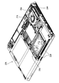
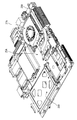
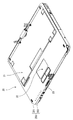
図8および図9は、図1に外観を示すノートPCの本体ユニットの、それぞれ上面および底面を示す斜視図である。図9では、底面側筐体部材202の一部を取り去って本体ユニット20の内容物を図示している。また図10は、図9の、HDDおよびファンの部分を示す拡大斜視図である。さらに図11は、本体ユニットの内容物のうちのプリント配線基板であるメインボードとそのメインボードに固定された各種部品を示す図である。図10および図11では、HDD26はメインボード25から取り外し、HDD26の配置位置を想像線(二点鎖線)で示してある。
8 and 9 are perspective views showing a top surface and a bottom surface, respectively, of the main unit of the notebook PC whose appearance is shown in FIG. In FIG. 9, the contents of the
図8には、図1と同じく、本体ユニット20の上面にキーボード21およびタッチパッド22が配置されており、前端面には吸気口23が設けられている。
In FIG. 8, as in FIG. 1, a
また図9には、図8にも示す吸気口23のほか、本体ユニットの筐体側面に形成された排気口24(図1を合わせて参照)が示されている。
FIG. 9 shows an exhaust port 24 (see also FIG. 1) formed on the side surface of the main unit unit in addition to the
また、吸気口23の近傍にはHDD26が配置されている。また排気口24aの近傍には、放熱フィン28が配置され、さらに、排気口24との間に放熱フィン28を挟んだ位置にファン27が配置されている。このファン27は、吸気口23との位置関係で説明すると、その吸気口23が形成された前端面との間にHDD26を置いた位置に配置されている。これらHDD26、ファン27、および放熱フィン28は、図10に示すように、メインボード25上に搭載されている。このファン27は、上下両面から空気を吸い込み放熱フィン28側の側面から空気を吹き出すタイプのファンである。さらにメインボード25上の、メインボード25と放熱フィン28とに挟まれた位置には、CPULSI(図示せず)が搭載されている。このCPULSIはCPUが搭載されプログラムを実行する演算機能を有するLSIであって、動作に伴い大量の熱を発生させる。その発生した熱は放熱フィン28に伝達される。放熱フィン28に伝達された熱はファン27により送り出された空気が放熱フィン28の隙き間を通る際に放熱フィン28から空気に伝熱される。この伝熱により温められた空気は排気口24から本体ユニット20の筐体の外部に輩出される。また、ファン27は、放熱フィン28に伝熱された熱を奪うだけでなく、吸気口23からファン27に至る空気流路上にあるHDD26等の部品の空冷も担っている。
An
図10および図11に示すように、メインボード25のHDD26と重なる部分には、第1の通気口251が形成されている。
As shown in FIGS. 10 and 11, a
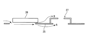
図12は、本実施形態のノートPCの本体ユニットの底面図である。また、図13は、図12に示す矢印A−Aに沿う断面を示す断面図、図14は、図13に示す円Rの部分の拡大断面図である。また図15は、図14,図15の断面における空気の流れを示した模式図である。 FIG. 12 is a bottom view of the main unit of the notebook PC according to the present embodiment. 13 is a cross-sectional view showing a cross section along the arrow AA shown in FIG. 12, and FIG. 14 is an enlarged cross-sectional view of a portion of a circle R shown in FIG. FIG. 15 is a schematic diagram showing the air flow in the cross sections of FIGS. 14 and 15.
図13,図14に示すように、HDD26は、本体ユニット20の筐体の、一周する側面の一部である前端面に形成された吸気口23との間に少し隙き間を空けて、その吸気口23に隣接する位置に配置されている。またこのHDD26は、筐体の厚み方向については、底面側筐体部材202によって形成される筐体の底面に隣接した位置に配置されている。また、メインボード25は、筐体底面との間にHDD26を挟んだ深さ位置においてその筐体底面に沿って、吸気口23が形成された前端面に近接あるいは接触した位置を含んで広がっている。また、吸気口23は、筐体前端面であって、メインボード25よりも底面側に形成されている。
As shown in FIGS. 13 and 14, the
ここで、図13,図14に示すように、メインボード25には、図10,図11にも示す第1の通気口251が示されている。この第1の通気口251は、HDD26と重なる位置からそのHDD26よりも筐体前端面側、すなわち吸気口23側に外れた位置まで広がって形成されている。また、HDD26との間にその第1の通気口251を挟んだ上面側には、PCカードが装填されるPCカードコネクタ29が配置されている。
Here, as shown in FIGS. 13 and 14, the
またメインボード25の、ファン27と重なる部分には第2の通気口252が形成されている。
A
このため、吸気口23から吸い込まれた空気は、第1の通気口251を通過してHDD26とPCカードコネクタ29との間に流れ込み、HDD26とPCカードコネクタ29との間を通った後、一部の空気は、矢印A方向に進んで第2の通気口252からファン27に吸い込まれ、他の一部の空気は矢印B方向に進んで底面側からファン27に吸い込まれる。ファン27に吸い込まれた空気は、前述の通り、放熱フィン28(例えば図10参照)側の側面から吹き出され、放熱フィン28の間を通る間に放熱フィン28の熱を吸収して排気口24から外部に排気される。このように、この実施形態の場合、HDD26に沿って空気が円滑に流れ、HDD26が効果的に空冷される。
Therefore, the air sucked from the
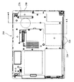
図16はHDDの底面を示した図、図17は、本体ユニット筐体内部の、HDDが配置される領域を示した図である。 FIG. 16 is a diagram showing the bottom surface of the HDD, and FIG. 17 is a diagram showing an area in the main unit housing where the HDD is arranged.
図16に示すHDD26の底面は、図17に示すHDD配置領域に配置されたときにメインボード25側を向く面である。このHDD26の底面には、HDD用の回路基板261が広がっており、そのほぼ中央部の回路基板261に設けられた開口と重なる位置に、モータ262が配置されている。このモータ262は、このHDD26に内蔵されている記憶媒体であるハードディスク(図示せず)を回転させるモータである。このHDD26では、このモータ262の発熱が大きく、また、このモータ262の寿命がHDD26の寿命に大きくかかわっており、したがってこのモータ262をできるだけ冷却して長寿命化を図ることが好ましい。さらにこの図16には、HDDの一側面にコネクタ263が示されている。このコネクタ263は、図17に示すHDD配置領域に配置されたときに、そのHDD配置領域の一辺に設けられたコネクタ95と結合する。このHDD26は、その四隅のネジ止め部分264でネジ止めされる。
The bottom surface of the
図17に示すHDD配置領域にはメインボード25が広がっており、そのメインボード25には第1の通気口251が形成されている。この第1の通気口251の、吸気口23寄りの一部分は、図13,図14に示した通り、この上に重ねられるHDD26と重なった領域から外れて、さらに吸気口23に寄った位置まで広がっている。ここで、空気流路の点のみを考慮すれば第1の通気口251はできる限り広いことが好ましいが、メインボード上の配線スペースなどを考慮すると、むやみに拡げることはできない。ただし、HDD26の発熱の原因はモータ262の回転にあり、このため第1の通気口251はこのモータ262と重なる領域にまでは広げられている。
A
ここで、HDD26の底面には図16に示すように回路基板261が広がっている。HDD26は、四隅のネジ止め部分264(図16参照)のみメインボード25に接触し、回路基板261はメインボードとは接触しない。それでもさらに、メインボード25の、HDD26と重なる領域に絶縁シートが敷かれることがある。絶縁シートが敷かれると、メインボード25上の配線とHDD26の底面の回路基板261上の配線との間が一層確実に絶縁される。このような絶縁シートがメインボード25上に敷かれるときは、その絶縁シートについてもメインボード25に設けられた第1の通気口251に応じた、例えば第1の通気口251と同じ形状の通気口が設けられる。
Here, a
次にメインボードに形成された第1の通気口の変形例を説明する。 Next, a modification of the first vent formed in the main board will be described.
図18および図19は、変形例における、それぞれ図14および図15に対応する図である。 18 and 19 are diagrams corresponding to FIGS. 14 and 15, respectively, in the modification.
上述の実施形態の場合、メインボード25に形成された第1の通気口251は、吸気口23側についてはHDD26と重なった領域よりもさらに吸気口23側にまで広がっているが、吸気口23から離れた側(ファン27側)についてはHDD26と重なった領域までしか広がっていない。
In the case of the above-described embodiment, the
これに対し、図18,図19に示す変形例の場合、第1の通気口251は、HDD26と重なる位置よりも吸気口23側に外れた位置まで広がるとともにさらに、HDD26よりも吸気口23から離れた側(ファン27側)に外れた位置まで広がった広がり領域251aを有する。このように、空気の流れに沿う方向についてHDD26の上流側と下流側との双方についてHDD26から外れた位置まで広がる開口を形成すると、空気の流れが一層円滑になり、HDD26が一層効果的に空冷される。
On the other hand, in the modified examples shown in FIGS. 18 and 19, the
尚、ここでは、HDDを本件にいう電子部品の例として説明したが、HDDに限られず、空気の流路上にあってメインボードと重なるように配置される電子部品であれば本件を適用することができる。 Here, the HDD has been described as an example of the electronic component in this case. However, the present invention is not limited to the HDD, and may be applied to any electronic component that is arranged on the air flow path so as to overlap the main board. Can do.
また、本件ではノートPCを例に挙げて説明したが、本件は、ノートPCに限らず空冷を行なう必要のある電子機器に広く適用することができる。 In this case, the notebook PC is described as an example. However, the present invention is not limited to the notebook PC and can be widely applied to electronic devices that need to be air-cooled.
10 ノートPC
20,20A 本体ユニット
21,21A キーボード
22,22A タッチパッド
23,23A 吸気口
24,24A,24a 排気口
25,25A メインボード
26,26A HDD
27,27A ファン
28,28A 放熱フィン
29 カードコネクタ
30 表示ユニット
31 表示画面
32 電源スイッチ
95,263 コネクタ
200 筐体
201 上面側筐体部材
202 底面側筐体部材
251,252 通気口
251a 広がり領域
261 回路基板
262 モータ10 Notebook PC
20,
27,
Claims (6)
前記筐体内の、前記側面を構成する第1側面部分との間に隙き間を空けて該第1側面部分に隣接した位置に配置された電子部品と、
前記第1面との間に前記電子部品を挟んだ深さにおいて該第1面に沿って、前記第1側面部分に接触又は近接した位置を含んで広がる基板とを有し、
前記筐体が、前記第1側面部分であって前記基板よりも前記第1面寄りの部分に形成された吸気口と、該吸気口から流入し前記電子部品に沿って流れた空気を排出する排気口とを有し、
前記基板が、前記電子部品と重なる位置から該電子部品よりも前記第1側面部分側に外れた位置まで広がって形成された第1の通気口を有することを特徴とする電子機器。A housing having a first surface and a second surface facing each other, and a side surface that makes a round along the periphery of the first surface and the second surface and defines an internal space together with the first surface and the second surface;
An electronic component disposed in a position adjacent to the first side surface portion with a gap between the first side surface portion constituting the side surface in the housing;
A substrate that extends along the first surface at a depth that sandwiches the electronic component between the first surface and the first surface portion, including a position that is in contact with or close to the first side surface portion;
The casing is an air inlet formed in the first side surface portion and closer to the first surface than the substrate, and exhausts air that flows from the air inlet and flows along the electronic component. An exhaust port,
The electronic apparatus according to claim 1, wherein the board has a first ventilation port formed so as to extend from a position overlapping the electronic component to a position distant from the electronic component toward the first side surface portion.
前記基板がさらに、前記ファンと重なる位置に形成された、該基板の前記第2面側を向いた面に沿って流れる空気を該ファンに流入させる第2の通気口を有することを特徴とする請求項1又は2記載の電子機器。A fan mounted on a surface facing the first surface at a position where the electronic component is placed between the substrate and the first side surface portion;
The board further includes a second vent hole that is formed at a position overlapping the fan, and that allows air flowing along the surface of the board facing the second surface side to flow into the fan. The electronic device according to claim 1 or 2.
Applications Claiming Priority (1)
| Application Number | Priority Date | Filing Date | Title |
|---|---|---|---|
| PCT/JP2009/065218 WO2011024319A1 (en) | 2009-08-31 | 2009-08-31 | Electronic apparatus |
Publications (2)
| Publication Number | Publication Date |
|---|---|
| JPWO2011024319A1 JPWO2011024319A1 (en) | 2013-01-24 |
| JP5265012B2 true JP5265012B2 (en) | 2013-08-14 |
Family
ID=43627443
Family Applications (1)
| Application Number | Title | Priority Date | Filing Date |
|---|---|---|---|
| JP2011528594A Expired - Fee Related JP5265012B2 (en) | 2009-08-31 | 2009-08-31 | Electronics |
Country Status (3)
| Country | Link |
|---|---|
| US (1) | US20120127663A1 (en) |
| JP (1) | JP5265012B2 (en) |
| WO (1) | WO2011024319A1 (en) |
Families Citing this family (7)
| Publication number | Priority date | Publication date | Assignee | Title |
|---|---|---|---|---|
| JP5813382B2 (en) | 2011-06-09 | 2015-11-17 | 富士通株式会社 | Electronic equipment |
| US9268377B2 (en) * | 2011-12-28 | 2016-02-23 | Intel Corporation | Electronic device having a passive heat exchange device |
| JP5966731B2 (en) * | 2012-07-30 | 2016-08-10 | 富士通株式会社 | Electronics |
| US9134757B2 (en) * | 2012-09-28 | 2015-09-15 | Intel Corporation | Electronic device having passive cooling |
| US8982555B2 (en) * | 2012-09-28 | 2015-03-17 | Intel Corporation | Electronic device having passive cooling |
| US20150065942A1 (en) | 2013-08-30 | 2015-03-05 | The Procter & Gambie Company | Visually perceptible tampon housed within an applicator |
| US10768676B2 (en) * | 2017-09-07 | 2020-09-08 | Intel Corporation | Docking systems and methods for electronic devices |
Citations (3)
| Publication number | Priority date | Publication date | Assignee | Title |
|---|---|---|---|---|
| JPS6358399U (en) * | 1986-10-01 | 1988-04-19 | ||
| JP2009069708A (en) * | 2007-09-17 | 2009-04-02 | Ricoh Co Ltd | Electronic information storage device for image processing apparatus and image processing device |
| JP2009117493A (en) * | 2007-11-02 | 2009-05-28 | Ricoh Co Ltd | Electrical equipment unit and image processor |
Family Cites Families (12)
| Publication number | Priority date | Publication date | Assignee | Title |
|---|---|---|---|---|
| US5121290A (en) * | 1990-06-25 | 1992-06-09 | At&T Bell Laboratories | Circuit pack cooling using perforations |
| US5694294A (en) * | 1995-01-27 | 1997-12-02 | Hitachi, Ltd. | Portable computer with fan moving air from a first space created between a keyboard and a first circuit board and a second space created between the first circuit board and a second circuit board |
| DE19607226A1 (en) * | 1996-02-27 | 1997-09-04 | Metabowerke Kg | Battery charger for electrical hand tools |
| JP2000172378A (en) * | 1998-12-04 | 2000-06-23 | Sony Corp | Auxiliary cooling system, auxiliary cooling method, electronic appliance and information processor |
| EP1340417B1 (en) * | 2000-12-08 | 2004-09-29 | Delta Energy Systems (Switzerland) AG | Electronics arrangement |
| US6567271B2 (en) * | 2001-03-05 | 2003-05-20 | Toshiba America Information Systems, Inc. | Circuit board interconnection and fan-mounting assembly for convective cooling |
| JP2005182936A (en) * | 2003-12-19 | 2005-07-07 | Fujitsu Ltd | Mounting device for storage device, integrating unit for storage device using it, electronic device which equipped with integrating unit |
| JP2006099856A (en) * | 2004-09-29 | 2006-04-13 | Hitachi Global Storage Technologies Netherlands Bv | Recording media drive |
| PL193094B1 (en) * | 2004-11-15 | 2007-01-31 | Adb Polska Sp | Pcb board with forced air circulation and device with the pcb board with forced air circulation |
| JP4744237B2 (en) * | 2005-08-26 | 2011-08-10 | 京セラミタ株式会社 | Circuit board cooling mechanism |
| JP2008071855A (en) * | 2006-09-13 | 2008-03-27 | Fujitsu Ltd | Electronic apparatus, and printed circuit board unit |
| US8189331B2 (en) * | 2010-05-25 | 2012-05-29 | Hewlett-Packard Development Company, L.P. | Thermal management systems and methods |
-
2009
- 2009-08-31 JP JP2011528594A patent/JP5265012B2/en not_active Expired - Fee Related
- 2009-08-31 WO PCT/JP2009/065218 patent/WO2011024319A1/en active Application Filing
-
2012
- 2012-01-30 US US13/361,297 patent/US20120127663A1/en not_active Abandoned
Patent Citations (3)
| Publication number | Priority date | Publication date | Assignee | Title |
|---|---|---|---|---|
| JPS6358399U (en) * | 1986-10-01 | 1988-04-19 | ||
| JP2009069708A (en) * | 2007-09-17 | 2009-04-02 | Ricoh Co Ltd | Electronic information storage device for image processing apparatus and image processing device |
| JP2009117493A (en) * | 2007-11-02 | 2009-05-28 | Ricoh Co Ltd | Electrical equipment unit and image processor |
Also Published As
| Publication number | Publication date |
|---|---|
| US20120127663A1 (en) | 2012-05-24 |
| WO2011024319A1 (en) | 2011-03-03 |
| JPWO2011024319A1 (en) | 2013-01-24 |
Similar Documents
| Publication | Publication Date | Title |
|---|---|---|
| JP5265012B2 (en) | Electronics | |
| JP4982590B2 (en) | Display device and electronic device | |
| JP4267629B2 (en) | Electronics | |
| CN101174172B (en) | Housing temperature suppressing structure in electronic device and portable computer | |
| JP5927539B2 (en) | Electronics | |
| JP2011238063A (en) | Electronic apparatus | |
| JP5950228B2 (en) | Electronics | |
| JP4823374B1 (en) | Electronics | |
| JP5725039B2 (en) | Cooling unit, electronic device and guide member | |
| JP2011233849A (en) | Cooling device, electronics and heat sink | |
| JP2007047998A (en) | Electronic component cooling structure and information processor | |
| JP2009015385A (en) | Electronic equipment | |
| JP2008186291A (en) | Portable electronic equipment | |
| WO2014103371A1 (en) | Electronic device | |
| US9122452B2 (en) | Electronic device | |
| JP5733144B2 (en) | Electronics | |
| JP2013251452A (en) | Electronic apparatus | |
| JP2013250880A (en) | Electronic apparatus | |
| JP4734427B2 (en) | Electronics | |
| JP5533458B2 (en) | Heat receiver, liquid cooling unit and electronic equipment | |
| JP4171028B2 (en) | Electronics | |
| JP2009086704A (en) | Electronic device | |
| JP5066294B2 (en) | Electronics | |
| JP2013140501A (en) | Information processing device | |
| JP7248747B2 (en) | Electronics |
Legal Events
| Date | Code | Title | Description |
|---|---|---|---|
| TRDD | Decision of grant or rejection written | ||
| A01 | Written decision to grant a patent or to grant a registration (utility model) |
Free format text: JAPANESE INTERMEDIATE CODE: A01 Effective date: 20130423 |
|
| A61 | First payment of annual fees (during grant procedure) |
Free format text: JAPANESE INTERMEDIATE CODE: A61 Effective date: 20130430 |
|
| R150 | Certificate of patent or registration of utility model |
Free format text: JAPANESE INTERMEDIATE CODE: R150 Ref document number: 5265012 Country of ref document: JP Free format text: JAPANESE INTERMEDIATE CODE: R150 |
|
| S111 | Request for change of ownership or part of ownership |
Free format text: JAPANESE INTERMEDIATE CODE: R313117 |
|
| R350 | Written notification of registration of transfer |
Free format text: JAPANESE INTERMEDIATE CODE: R350 |
|
| S531 | Written request for registration of change of domicile |
Free format text: JAPANESE INTERMEDIATE CODE: R313531 |
|
| R350 | Written notification of registration of transfer |
Free format text: JAPANESE INTERMEDIATE CODE: R350 |
|
| LAPS | Cancellation because of no payment of annual fees |