JP5263765B2 - Airway securing device - Google Patents
Airway securing device Download PDFInfo
- Publication number
- JP5263765B2 JP5263765B2 JP2008235737A JP2008235737A JP5263765B2 JP 5263765 B2 JP5263765 B2 JP 5263765B2 JP 2008235737 A JP2008235737 A JP 2008235737A JP 2008235737 A JP2008235737 A JP 2008235737A JP 5263765 B2 JP5263765 B2 JP 5263765B2
- Authority
- JP
- Japan
- Prior art keywords
- airway
- bag
- securing device
- airway securing
- air
- Prior art date
- Legal status (The legal status is an assumption and is not a legal conclusion. Google has not performed a legal analysis and makes no representation as to the accuracy of the status listed.)
- Expired - Fee Related
Links
- 230000007246 mechanism Effects 0.000 claims description 96
- 208000008784 apnea Diseases 0.000 claims description 31
- 206010021079 Hypopnoea Diseases 0.000 claims description 28
- 238000005452 bending Methods 0.000 claims description 27
- 230000007958 sleep Effects 0.000 claims description 21
- 206010036790 Productive cough Diseases 0.000 claims description 20
- 208000024794 sputum Diseases 0.000 claims description 20
- 210000003802 sputum Anatomy 0.000 claims description 20
- 230000005856 abnormality Effects 0.000 claims description 17
- 241001669679 Eleotris Species 0.000 claims description 9
- 210000003128 head Anatomy 0.000 description 42
- 210000000214 mouth Anatomy 0.000 description 39
- 230000029058 respiratory gaseous exchange Effects 0.000 description 23
- 230000005540 biological transmission Effects 0.000 description 18
- 201000002859 sleep apnea Diseases 0.000 description 15
- 210000001847 jaw Anatomy 0.000 description 14
- 208000024891 symptom Diseases 0.000 description 11
- 238000001514 detection method Methods 0.000 description 8
- 206010015037 epilepsy Diseases 0.000 description 8
- 238000010586 diagram Methods 0.000 description 7
- 238000000034 method Methods 0.000 description 7
- 208000024658 Epilepsy syndrome Diseases 0.000 description 6
- 208000002877 Epileptic Syndromes Diseases 0.000 description 6
- 230000000241 respiratory effect Effects 0.000 description 6
- 230000003187 abdominal effect Effects 0.000 description 5
- 239000000463 material Substances 0.000 description 5
- 238000001356 surgical procedure Methods 0.000 description 5
- 208000000884 Airway Obstruction Diseases 0.000 description 4
- 206010002091 Anaesthesia Diseases 0.000 description 4
- 210000001015 abdomen Anatomy 0.000 description 4
- 230000037005 anaesthesia Effects 0.000 description 4
- 210000001738 temporomandibular joint Anatomy 0.000 description 4
- 230000008859 change Effects 0.000 description 3
- 230000000694 effects Effects 0.000 description 3
- 230000037303 wrinkles Effects 0.000 description 3
- 125000002066 L-histidyl group Chemical group [H]N1C([H])=NC(C([H])([H])[C@](C(=O)[*])([H])N([H])[H])=C1[H] 0.000 description 2
- 208000003028 Stuttering Diseases 0.000 description 2
- 238000011513 continuous positive airway pressure therapy Methods 0.000 description 2
- 238000011257 definitive treatment Methods 0.000 description 2
- 208000014617 hemorrhoid Diseases 0.000 description 2
- 230000006872 improvement Effects 0.000 description 2
- 125000000391 vinyl group Chemical group [H]C([*])=C([H])[H] 0.000 description 2
- 229920002554 vinyl polymer Polymers 0.000 description 2
- 206010013496 Disturbance in attention Diseases 0.000 description 1
- 206010013642 Drooling Diseases 0.000 description 1
- 206010020772 Hypertension Diseases 0.000 description 1
- 206010062519 Poor quality sleep Diseases 0.000 description 1
- 208000037656 Respiratory Sounds Diseases 0.000 description 1
- 208000008630 Sialorrhea Diseases 0.000 description 1
- 206010041235 Snoring Diseases 0.000 description 1
- 239000000853 adhesive Substances 0.000 description 1
- 230000001070 adhesive effect Effects 0.000 description 1
- QVGXLLKOCUKJST-UHFFFAOYSA-N atomic oxygen Chemical compound [O] QVGXLLKOCUKJST-UHFFFAOYSA-N 0.000 description 1
- 230000008901 benefit Effects 0.000 description 1
- 230000008602 contraction Effects 0.000 description 1
- 230000007423 decrease Effects 0.000 description 1
- 208000002925 dental caries Diseases 0.000 description 1
- 230000037213 diet Effects 0.000 description 1
- 235000005911 diet Nutrition 0.000 description 1
- 201000010099 disease Diseases 0.000 description 1
- 208000037265 diseases, disorders, signs and symptoms Diseases 0.000 description 1
- 238000005187 foaming Methods 0.000 description 1
- 208000019622 heart disease Diseases 0.000 description 1
- 210000004373 mandible Anatomy 0.000 description 1
- 238000004519 manufacturing process Methods 0.000 description 1
- 210000003205 muscle Anatomy 0.000 description 1
- 231100000862 numbness Toxicity 0.000 description 1
- 229910052760 oxygen Inorganic materials 0.000 description 1
- 239000001301 oxygen Substances 0.000 description 1
- 201000001245 periodontitis Diseases 0.000 description 1
- 230000002265 prevention Effects 0.000 description 1
- 239000011347 resin Substances 0.000 description 1
- 229920005989 resin Polymers 0.000 description 1
- 210000002345 respiratory system Anatomy 0.000 description 1
- 230000004044 response Effects 0.000 description 1
- 230000000087 stabilizing effect Effects 0.000 description 1
- 208000011580 syndromic disease Diseases 0.000 description 1
- 238000002560 therapeutic procedure Methods 0.000 description 1
- 230000007306 turnover Effects 0.000 description 1
Images


Classifications
-
- A—HUMAN NECESSITIES
- A61—MEDICAL OR VETERINARY SCIENCE; HYGIENE
- A61F—FILTERS IMPLANTABLE INTO BLOOD VESSELS; PROSTHESES; DEVICES PROVIDING PATENCY TO, OR PREVENTING COLLAPSING OF, TUBULAR STRUCTURES OF THE BODY, e.g. STENTS; ORTHOPAEDIC, NURSING OR CONTRACEPTIVE DEVICES; FOMENTATION; TREATMENT OR PROTECTION OF EYES OR EARS; BANDAGES, DRESSINGS OR ABSORBENT PADS; FIRST-AID KITS
- A61F5/00—Orthopaedic methods or devices for non-surgical treatment of bones or joints; Nursing devices; Anti-rape devices
- A61F5/56—Devices for preventing snoring
Landscapes
- Health & Medical Sciences (AREA)
- Otolaryngology (AREA)
- Pulmonology (AREA)
- Nursing (AREA)
- Orthopedic Medicine & Surgery (AREA)
- Engineering & Computer Science (AREA)
- Biomedical Technology (AREA)
- Heart & Thoracic Surgery (AREA)
- Vascular Medicine (AREA)
- Life Sciences & Earth Sciences (AREA)
- Animal Behavior & Ethology (AREA)
- General Health & Medical Sciences (AREA)
- Public Health (AREA)
- Veterinary Medicine (AREA)
- Orthopedics, Nursing, And Contraception (AREA)
- Instructional Devices (AREA)
Description
本発明は、鼾や睡眠時無呼吸症候群に悩む人々の治療、症状改善、あるいは手術中の気道確保のための気道確保装置に関する。 The present invention relates to an airway securing device for treating people suffering from epilepsy and sleep apnea syndrome, improving symptoms, or securing an airway during surgery.
睡眠時に大きな音を発する鼾は周囲への迷惑になるだけでなく、自身の眠りの浅さにも繋がる。成人の男性で約40パーセント、女性でも約15パーセントが鼾を自覚しているとの報告があり、その解消法に大きな関心が集まっているが、未だ決定的な治療法は見つかっていない。 A kite that makes a loud sound when sleeping not only disturbs the surroundings, but also leads to a shallow depth of sleep. There are reports that about 40 percent of adult men and about 15 percent of women are aware of hemorrhoids, and there is a great deal of interest in how to eliminate it, but no definitive treatment has yet been found.
睡眠時無呼吸症候群は、就寝中に気道が塞がり一時的な無呼吸や低呼吸を繰り返す病気である。体調不良、日中の集中力低下、居眠り運転などの原因となると言われており、さらに、睡眠時の無呼吸により体内の酸素が一次的に減ることで、それが高血圧、心臓病の遠因になっているという医学調査も報告されている。そのため、近年、その予防法や治療法に注目が集まっている。食事療法や体調管理、適した枕の形状など無呼吸症候群の治療や症状改善のための研究が行われているが、未だ決定的な治療法は見つかっていない。 Sleep apnea syndrome is a disease in which the respiratory tract is blocked during sleep and repeats temporary apnea and hypopnea. It is said to cause poor physical condition, poor concentration during the day, drowsy driving, etc.Furthermore, oxygen in the body decreases temporarily due to sleep apnea, which is a cause of high blood pressure and heart disease. Medical surveys have been reported. Therefore, in recent years, attention has been focused on the prevention methods and treatment methods. Research has been conducted on the treatment of apnea syndrome and improvement of symptoms such as diet, physical condition management, and suitable pillow shapes, but no definitive treatment has been found yet.
鼾および無呼吸・低呼吸の発生は、仰向けに寝た状態で筋肉が弛緩し口が半開きになり、下顎が後方に下がることにより、舌が後方に下がって気道を塞ぐことが主要な原因のひとつとされている。代表的な治療法としては、「スプリント」と呼ばれる口腔内装具を睡眠中に装着し、舌や下顎を前方に固定することで舌の後方の気道スペースを広げ、気道の閉塞を防ぐ療法が知られている(特許文献1参照)。また、専用の鼻マスクを介して強制的に空気を気道内に送り、陽圧をかける「CPAP療法」がある。その他、睡眠中に横向きに寝かせる枕(特許文献2、3参照)、あるいは頭部を後屈させる肩枕(特許文献4参照)なども知られている。
The main cause of epilepsy and apnea / hypopnea is that the muscles relax, the mouth opens halfway, the lower jaw lowers backward, and the tongue lowers backward to block the airway while lying on its back It is considered as one. As a typical treatment method, there is a therapy that prevents the obstruction of the airway by wearing an oral interior device called “sprint” during sleep and fixing the tongue and lower jaw forward to widen the airway space behind the tongue. (See Patent Document 1). In addition, there is “CPAP therapy” in which positive pressure is applied by forcibly sending air into the airway through a dedicated nasal mask. In addition, pillows (see
ところで、上述のスプリントは、虫歯や歯槽膿漏等の歯が欠損している場合には装着することができず、またCPAP療法は、中等乃至重症患者には有効であるものの比較的軽度の患者には不向きであるとの課題が残る。横向きに寝かせる枕を用いて鼾を予防する器具では、気道の閉塞を緩和する効果があるが、十分でなく、しかも睡眠中、横向きに寝かされるため、体位に無理を強いることになり、腕の痺れなどを誘発する可能性がある。頭部を後屈させる肩枕を用いて鼾を防止する器具では、やはり気道の閉塞を緩和する効果があるものの開口状態になり易く十分な気道確保ができず、しかも口腔内が乾燥するなど患者にとって不快感を与えてしまう。 By the way, the above-mentioned splint cannot be worn when teeth such as caries or alveolar pyorrhea are missing, and CPAP therapy is effective for moderate to severe patients but relatively mild patients. Remains an unsuitable problem. A device that prevents wrinkles using a pillow that can be laid sideways is effective in relieving airway obstruction, but it is not sufficient, and because it is laid down sideways during sleep, it forces the posture to be unreasonable, May cause numbness. Patients with a device that prevents wrinkles by using a shoulder pillow that causes the head to bend backwards, although it still has an effect of relieving airway obstruction, it tends to be open and sufficient airway cannot be secured, and the oral cavity is dry, etc. It will be uncomfortable for you.
また例えば、手術中の麻酔による入眠時の気道確保が必要な場合にも、簡便な装置で気道確保できることが望まれる。 In addition, for example, when it is necessary to secure the airway during sleep due to anesthesia during surgery, it is desirable that the airway can be secured with a simple device.
本発明は、上述の点に鑑み、就眠体位の強要、不快感を与えずに、より気道の確保を十分にして鼾および睡眠時無呼吸症候群の治療、症状の改善、その他の気道確保などを可能にした気道確保装置を提供するものである。 In view of the above-mentioned points, the present invention makes it easy to sleep and maintain the airway without giving discomfort, to treat sputum and sleep apnea syndrome, improve symptoms, and secure other airways. An airway securing device that has been made possible is provided.
本発明に係る気道確保装置は、就眠者の身体外部に装着可能な装着体を有して気道を確保する気道確保装置であって、前記装着体が、前記就眠者の下顎と胸部の上方部位との間に配置され、当該就眠者の口を閉じて顎先を挙上させる第1の機構と、前記就眠者の後頭部と頸部の下方部位との間に配置され、当該就眠者の頭部を後屈させる第2の機構とを備え、前記第1及び第2の機構は、各々が空気室を有して空気により膨張、収縮する袋状体で形成され、前記就眠者の仰臥姿勢において、前記第1の機構では、当該機構の前記空気室に空気が供給されると膨張して当該機構の前記袋状体が就眠者の顎に向かって隆起し、前記第2の機構では、当該機構の前記空気室に空気が供給されると膨張して当該機構の前記袋状体が就眠者の肩部あるいは胸部を持ち上げることを特徴とする。
本発明の気道確保装置のより好ましい形態は、前記顎先を挙上させる第1の機構及び、前記頭部を後屈させる第2の機構を有する前記装着体が、着衣で形成されていることを特徴とする。
本発明の気道確保装置のより好ましい形態は、前記顎先を挙上させる第1の機構及び、前記頭部を後屈させる第2の機構を有する前記装着体が、首輪状本体で形成されていることを特徴とする。
本発明の気道確保装置のより好ましい形態は、前記装着体に、睡眠時の異常を検知する機構を備え、更に、前記顎先を挙上させる第1の機構及び前記頭部を後屈させる第2の機構を駆動する駆動装置と、前記異常を検知する機構の出力に基づいて前記第1の機構及び、前記第2の機構を駆動するように前記駆動装置を制御する制御装置とを有していることを特徴とする。
本発明の気道確保装置のより好ましい形態は、睡眠時の異常を検知する機構が、無呼吸・低呼吸を検知する手段及び鼾の発生を検知する手段の少なくともいずれか一方を有することを特徴とする。
An airway securing device according to the present invention is an airway securing device that secures an airway by having a mounting body that can be mounted on the outside of a sleeper's body, wherein the mounting body is located above the lower jaw and chest of the sleeper. Between the first mechanism for closing the sleeper's mouth and raising the tip of the chin, and between the back of the sleeper and the lower part of the neck, the sleeper's head and a second mechanism for buckled later section, the first and second mechanism, each inflated by air having an air chamber, is formed in a bag-like body to contract, supine posture of the sleeping person In the first mechanism, when air is supplied to the air chamber of the mechanism, the bag-like body of the mechanism expands toward the sleeper's jaw, and in the second mechanism, When air is supplied to the air chamber of the mechanism, the bag expands when the air is supplied to the shoulder of the sleeper. And wherein the Rukoto lift the chest.
In a more preferred form of the airway securing device of the present invention, the wearing body having the first mechanism for raising the chin and the second mechanism for bending the head backward is formed by clothing. It is characterized by.
In a more preferred form of the airway securing device of the present invention, the mounting body having a first mechanism for raising the chin and a second mechanism for bending the head backward is formed of a collar-shaped body. It is characterized by being.
More preferred form of the airway securing device of the present invention, the attachment body, the causes a mechanism to detect an abnormality during sleep, further buckled after the first mechanism and said head to elevate the jaw tip has a drive device for driving the second mechanism, wherein based on an output of the mechanism to detect an abnormality first mechanism and a controller for controlling the driving device to drive the second mechanism It is characterized by.
In a more preferred form of the airway securing device of the present invention, the mechanism for detecting abnormalities during sleep has at least one of means for detecting apnea / hypopnea and means for detecting the occurrence of sputum. To do.
本発明の気道確保装置では、睡眠時あるいは入眠時に必要に応じて口を閉じて顎先を挙上させる機構が駆動し、寝ている患者の口が閉じられ顎先が挙上される。さらに、頭部を後屈させる機構を有しているときは、この機構の駆動で頭部後屈がなされ、更なる気道スペースの広がりで、気道確保がより確実に行われる。
例えば、異常を検知する機構により鼾あるいは無呼吸・低呼吸を検知したときは、その検出信号に基づき、口を閉じて顎先を挙上させる機構が駆動し、寝ている患者の口が閉じられ顎先が挙上される。さらに必要に応じて頭部を後屈させる機構が駆動し、頭部後屈がなされる。これにより気道スペースが広がり、気道確保ができる。
In the airway securing device of the present invention, a mechanism that closes the mouth and raises the chin tip as needed during sleep or sleep is driven to close the mouth of the sleeping patient and raise the chin tip. Further, when the mechanism for bending the head is provided, the head is bent backward by driving the mechanism, and the airway is secured more reliably by further expanding the airway space.
For example, if a mechanism that detects abnormalities detects sputum or apnea / hypopnea, the mechanism that closes the mouth and raises the chin tip is driven based on the detection signal, and the sleeping patient's mouth closes. The tip of the jaw is raised. Further, a mechanism for bending the head backward is driven as necessary, and the head is bent backward. This widens the airway space and secures the airway.
本発明に係る気道確保装置によれば、口を閉じて顎先を挙上させる機構の駆動により口が閉じ、顎先が挙上されて気道が確保されるので、鼾および無呼吸症候群の治療、症状の改善、その他の気道の確保を図ることができる。本気道確保装置は、身体に装着されるので、就眠体位の強要(固定)をすることがなく、また患者に不快感を与えることがない。 According to the airway securing device of the present invention, the mouth is closed by driving the mechanism that closes the mouth and raises the chin, and the chin tip is raised to secure the airway, so that treatment of epilepsy and apnea syndrome , Improve symptoms and secure other airways. Since the present airway securing device is attached to the body, it does not force (fix) the sleeping position, and does not cause discomfort to the patient.
以下、図面を参照して本発明の実施の形態を説明する。 Embodiments of the present invention will be described below with reference to the drawings.
[第1実施の形態]
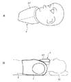
図1に、本発明に係る気道確保装置の第1実施の形態を示す。本実施の形態では、本気道確保装置を鼾および無呼吸症候群の治療装置に適用した例である。本実施の形態に係る気道確保装置1は、口を閉じて顎先を挙上させる機構5と、さらに好ましくは頭部を後屈させる機構6とを有した装着体3を備えている。口を閉じて顎先を挙上させる機構5と、頭部を後屈させる機構6は、装着体3に一体に取り付けた構成とすることが好ましいが、装着体3と別体に構成し、あるいは装着体3に対して着脱可能に構成し、使用時に装着体3に配置し、あるいは取り付けるようになすことも可能である。さらに、好ましくは、装着体3に睡眠時に異常を検知する機構を有する。この異常を検知する機構も、装着体3に一体に取り付けた構成とすることが好ましいが、装着体3と別体に構成し、あるいは装着体3に対して着脱可能に構成し、使用時に装着体3に配置し、あるいは取り付けるようになすことも可能である。装着体3に睡眠時に異常を検知する機構としは、無呼吸・低呼吸を検知する手段、鼾の発生を検知する手段のうちいずれか一つ以上を一体に有する。本例では、鼾あるいは無呼吸・低呼吸を検知する検出手段として、いわゆるセンサ4が用いられる。この装着体3は、身体(すなわち患者)2に装着されるものである。さらに、本装置1は、後述する制御装置14及び駆動装置15を備えている。この駆動装置15は機構5、6を駆動させる装置であり、制御装置14は、センサ4で得られた信号を基に鼾あるいは無呼吸・低呼吸の有無を判定し、駆動装置15へ指令を送る装置である。
[First Embodiment]
FIG. 1 shows a first embodiment of an airway securing device according to the present invention. In this embodiment, the airway securing device is applied to a treatment device for epilepsy and apnea syndrome. The airway securing
装着体3としては、本例では着衣、特にベスト(胴着)が用いられる。ベストの顎下にあたる位置、つまり前襟部には、空気により膨張、収縮する空気室、いわゆる袋状体7が設けられ、口を閉じて顎先を挙上させる機構5を構成している。袋状体7は、軽くて柔軟性を有する材料、例えばビニール系の材料で形成することができる。口を閉じて顎先を挙上させる機構5は、例えば互いに内通する4つの連結した袋部で形成され、装着体3であるベストの前襟部において、正常時に収縮された状態にある。ひとたび鼾あるいは無呼吸・低呼吸が確認されると、前襟部の袋状体は空気で満たされて膨張し、顎に向かって隆起することで顎下を押し、その結果、利用者の口は閉じられ、顎先が挙上される。図示の例では、口を閉じて顎先を挙上させる機構5は4つの袋状体を連結した構成であるが、たとえば1つの袋状体で構成することもでき、口を閉じて顎先を挙上させる機構5は様々な数や配置の袋状体により構成されうる。
As the mounting
頭部を後屈させる機構6としては、本例では空気により膨張、収縮する空気室、いわゆる袋状体8で形成される。この袋状体8は、軽くて柔軟性を有する材料、例えばビニール系の材料で形成することができる。この袋状体8は、枕状をなし、装着体3であるベストの背後で肩に対応する位置、すなわちベストの後襟部に取付けられる。この袋状体8は、空気により膨張して肩部あるいは胸部を持ち上げ、頭部を後屈させるように構成される。
In this example, the
センサ4としては、腹部と胸部の膨らみのパターンから吸気・呼気、無呼吸を検出するセンサ、鼾音・呼吸音を検出するマイクロホン、呼吸に伴う体幹−ベッド(布団)間の圧力分布変化を検出するシート状圧力分布計あるいは鼻(正確には鼻孔の下あたりの唇の上)に装着して吸気・呼気、無呼吸を検出するサーミスタなど既存のセンサを用いることができる。サーミスタは温度変化を呼吸パターンに変換して呼気の有無を検知する。勿論、呼気の有無と鼾音の有無の両方を検知できるセンサを用いることもできる。
The
本実施の形態では、そのうち、腹部と胸部とで膨張のパターンを検出して呼気の有無を検知するセンサを装着体3であるベストに一体に組み込む。本例のセンサ4は、抵抗線あるいは導電性ゴムなどを内蔵し、これにより伸縮量を検知することが可能なベルト状のセンサ部11と同様のセンサ部12とを有して構成される。
In the present embodiment, a sensor that detects the presence or absence of exhalation by detecting an expansion pattern between the abdomen and the chest is integrated in the vest that is the wearing
センサ4を通して得られた胸部と腹部の膨張パターンから無呼吸・低呼吸発生の有無が判断される。正常な呼吸時には、腹部と胸部の膨張パターンは同相である。しかし、気道が塞がれ呼吸が停止した状態では、腹部と胸部の膨張パターンが逆相になる。従って、この逆相パターンを検知することで無呼吸・低呼吸状態を検知することができる。なお、図1において、16は通常の枕を示す。
Presence / absence of apnea / hypopnea is determined from the expansion pattern of the chest and abdomen obtained through the
さらに、本実施の形態の気道確保装置1は、センサ4で検出した信号に基づいて、無呼吸・低呼吸の有無を判定し、その判定結果により口を閉じて顎先を挙上させる機構5、頭部を後屈させる機構6を駆動制御するための制御装置14と、制御装置14からの指令で口を閉じて顎先を挙上させる機構5、頭部を後屈させる機構6を駆動する駆動装置15を備えている。
Furthermore, the
この駆動装置15は、機構5、6を上述の袋状体7、8で構成したときには、袋状体7、8を空気により膨張、収縮させる機構を有する。すなわち、この駆動装置15では、症状が出たときに機構5、6へ空気を供給する機能と、正常に戻ったときに機構5、6から空気を抜く機能を備えている。空気を抜く機構としては、例えばバルブを開放して空気を放出する構成、負圧をかけて吸引する構成、その他の構成も可能である。袋状体7、8を機械的に収縮させる構成としても良い。駆動装置15としては、好ましくは吸気用に小型の電動エアポンプを、排気用に小型電磁弁を用いることができる。この電動エアポンプは、乾電池で作動するような低圧用のものでも充分機能すると思われる。
The
さらに、袋状体7,8を空気により膨張、収縮させる機構としては、例えば、バルブ(例えば空気供給、排気の切り替えバルブ、あるいは空気供給専用及び排気専用のバルブ、あるいは排気専用のバルブなど)を配置すると共に、装着体3に、常時袋状体7,8を収縮させる方向に弾性偏倚させる弾性部材、例えば弾性を有するゴムベルトなどを取り付けて構成することができる。袋状体7,8を膨張させるときは、弾性部材の弾性偏倚力に抗して空気を注入し膨張させる。袋状体7,8を収縮させるときは、バルブを開放すると共に、弾性部材の弾性偏倚力により収縮させる。
Further, as a mechanism for expanding and contracting the bag-
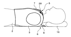
次に、第1実施の形態に係る気道確保装置1の動作を、図2を用いて説明する。患者は、装置1における装着体3、つまりベストを着込んで就眠する。図2は、頭を枕16に載せて仰向けに寝た状態を示す。
Next, the operation of the
図2Aは、正常時の状態を示す。このときは、口を閉じて顎先を挙上させる機構5である前襟部の袋状体7、及び頭部を後屈させる機構6である後襟部の袋状体8は収縮状態にある。
FIG. 2A shows a normal state. At this time, the bag-
次に、無呼吸症候群患者利用の場合において、呼吸停止の状態になると、腹部ベルトのセンサ部11からの呼吸パターンと、胸部ベルトのセンサ部12からの呼吸パターンが逆位相となることから、この両呼吸パターンの位相関係から制御装置14において、呼吸の有無を判定する。呼吸停止を判定したら、その判定結果に基づき制御装置14からの指令により、駆動装置15が駆動開始し、最初に駆動装置15から空気が前襟部の袋状体7へ送られる。
Next, in the case of use of apnea syndrome patients, when breathing is stopped, the respiratory pattern from the
これにより、図2Bに示すように、袋状体7が膨張し、患者の口は閉じられ顎先が挙上される。口が閉じられ、顎先が挙上されることにより、患者の気道スペースが広がる。この状態で、患者の症状によっては気道が確保され、呼吸が正常に戻る。
Thereby, as shown to FIG. 2B, the bag-
さらに、図2Cに示すように、前襟部の袋状体7が膨張した後、駆動装置15から後襟部の袋状体8へ空気が送られる。そして、この袋状体8が膨張し、患者の首あるいは胸部の一部を持ち上げることにより、頭部が後屈する。頭部後屈により更に患者の気道スペースが広がり、確実に気道が確保され、正常な呼吸に戻る。
Further, as shown in FIG. 2C, after the bag-
呼吸が正常に戻ったことをセンサ4で検知したならば、制御装置14で正常呼吸であることが判定される。その判定結果に基づき制御装置14からの指令により、駆動装置15では、排気駆動がなされる。これにより、両袋状体7、8内の空気が抜かれ、両袋状体7、8は収縮されて元に戻り、その結果、患者は図2Aの状態に戻る。
If the
呼吸停止を検知した後の両袋状体7及び8に対する動作制御としては、上述したように、両袋状体7、8に対して、呼吸停止を検知して空気を送って膨張させ、呼吸開始を検知して空気を抜いて収縮させることができる。その他、呼吸停止を検知し両袋状体7、8へ空気を送り、一定時間、膨張袋状体の形状を保ち、その間に気道確保することを予測して、一定時間後に両袋状体7、8を収縮させることもできる。さらには、患者の症状により、袋状体7のみを動作する、あるいは両袋状体7、8を動作させることができる。このように袋状体7、8に対する駆動制御の仕方は、患者の症状に合わせて種々選択することができる。各駆動制御の仕方に応じて、制御装置14及び駆動装置15の制御系が設定される。
As described above, as the operation control for both the bag-
上述の第1実施の形態に係る気道確保装置1によれば、前襟部に袋状体7を取付け、後襟部に袋状体8を取り付けた装着体3を着用することにより、就眠中、センサ4で無呼吸・低呼吸になったことを検知したときには、袋状体7、または袋状体7、8が膨張し、患者の口は閉られ顎先が挙上され、さらに頭部後屈がなされ、気道を確保することができ、呼吸を回復させることができる。
According to the
第1実施の形態の気道確保装置1は、就眠中の体位を強要することがない。すなわち、患者は自由に体位を変えることが可能であり、体位を固定することがないので、患者にとって負担を軽減することができる。例えば、従来の横向きに寝かせる治療具の場合は、横向きに固定されるので、寝返りができないとか、片側の腕が痺れる等の不快感を与え、頭部後屈のみを行う治療具の場合は、口を開き続けるので口腔内が乾燥し不快感を与えていた。しかし、本装置1ではその点も改善される。
The
装着体3としてのベスト、両袋状体7、8はいずれも軽く柔らかいので、患者に不要な圧迫感を与えず、寝相の悪い患者でも気道確保装置1を確実に動作させることができる。また、本実施の形態の気道確保装置1は、携帯も可能であり、旅行先などでも使用可能である。枕16の構造は規制されないので、自分の好みの枕を使用できる。
Since both the vest as the mounting
なお、上記の気道確保装置1において、頭部を後屈させる袋状体8のみを駆動させることも可能であるが、この場合口が開いて口腔内が乾燥するなど患者に不快感を与える虞れがあるので、口を閉じて顎先を挙上させる袋状体7と併用することが好ましい。
上記の気道確保装置1において、口を閉じて顎先を挙上させる袋状体7のみ一体に有する、あるいは頭部を後屈させる袋状体8のみ一体に有する、あるいは両袋状体7及び8を一体に有する構成とすることができる。
In the
In the
上述の気道確保装置1において、駆動装置15としては、必要な空気圧を袋状体7、8へ供給したら、それ以上に気圧が上がらないように気圧を制限する機能が設けられる。前襟部の袋状体7への気圧と、後襟部の袋状体8への気圧との最適値が違うときは、駆動装置15を2つ設けることができる。
In the above-described
図2では、袋状体7を先に駆動させ、次いで袋状体8を駆動させるようにしたが、その他、袋状体7,8を同時に駆動させることも可能であり、あるいは先に袋状体8を駆動させ、次いで袋状体7を駆動させることも可能である。さらには、袋状体8のみを駆動させることも可能である。すなわち、袋状体7,8の駆動制御の仕方は、前述した駆動制御の仕方も含めて、患者の症状に合わせて選択でき、その駆動制御に応じて、制御装置14及び駆動装置15の制御系が設定される。
In FIG. 2, the bag-
[第2実施の形態]
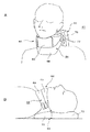
図3に、本発明に係る気道確保装置の第2実施の形態を示す。本実施の形態の気道確保装置は、鼾および無呼吸症候群の治療装置に適用した例である。本実施の形態に係る気道確保装置21は、図1の気道確保装置1において、頭部を後屈させる機構6を省略して構成される。すなわち、本実施の形態に係る気道確保装置21は、鼾あるいは無呼吸・低呼吸を検知する検出手段、いわゆるセンサ4と、顎関節を閉じる機構5とを一体に有した装着体3を備えている。さらに、本装置21は、制御装置14と駆動装置15を備えている。制御装置14は、センサ4で検出した信号に基いて、無呼吸・低呼吸あるいは鼾の有無を判定し、その判定結果を駆動装置15へ送り、駆動装置15を駆動制御する。駆動装置15は、制御装置14からの指令に基づいて顎関節を閉じる機構5を駆動する。
[Second Embodiment]
FIG. 3 shows a second embodiment of the airway securing device according to the present invention. The airway securing device of the present embodiment is an example applied to a treatment device for epilepsy and apnea syndrome. The
本実施の形態では、図1で説明したと同様に、装着体3として着衣、特にベスト(胴着)が用いられる。また、顎関節を閉じる機構5としては、空気により膨張、収縮する袋状体7で形成される。センサ4としては、腹部と胸部の呼吸パターンを検出するセンサ部11、12で構成される。さらに、駆動装置15は、症状が出たときに機構5へ空気を供給する機能と、正常に戻ったときに機構5から空気を抜く機能を備えている。その他の構成については、図1で説明したと同様であるので、重複説明を省略する。
In the present embodiment, as described with reference to FIG. 1, clothes, in particular, a vest (bodice) is used as the mounting
次に、第2実施の形態に係る気道確保装置21の動作を図4を用いて説明する。患者は、気道確保装置21における装着体3を着込んで就眠する。
図4Aは、正常時の状態を示す。このときは、口を閉じて顎先を挙上させる機構5である前襟部の袋状体7は収縮状態にある。
Next, the operation of the
FIG. 4A shows a normal state. At this time, the bag-
次に、無呼吸症候群患者が本装置21を利用する場合において、呼吸停止の状態になると、腹部ベルトのセンサ部11からの呼吸パターンと、胸部ベルトのセンサ部12からの呼吸パターンが逆位相となることから、この両呼吸パターンの位相関係から制御装置14において、呼吸停止を判定する。そして、判定結果に基づき制御装置14からの指令により、駆動装置15が駆動開始し、駆動装置15から空気が前襟部の袋状体7へ送られる。
Next, when an apnea syndrome patient uses this
これにより、図4Bに示すように、袋状体7が膨張し、患者の口が閉じられ顎先が挙上される。口が閉じられ、顎先が挙上されることにより、患者の気道スペースが広がる。この状態で、気道が確保され、呼吸が正常に戻る。
Thereby, as shown to FIG. 4B, the bag-
第2実施の形態に係る気道確保装置21によれば、上例と同様に、前襟部に袋状体7を取付けた装着体3であるベストを着用して就眠することにより、就眠中、無呼吸症候群患者が無呼吸・低呼吸になったときには、袋状体7が膨張し、患者の顎関節が閉じられ、気道を確保することができ、呼吸を回復させることができる。その他、就寝体位を固定せず、患者に不快感を与えないこと、携帯が可能であること等、第1実施の形態の気道確保装置1で説明したと同様の効果を奏する。
According to the
図5に、口が閉じられ顎先が挙上される機構5として用いられる前襟部の袋状体の他の例を示す。この袋状体27は、顎先と顎両側に対応した3つの部分からなる袋から構成される。この袋状体27は上下方向に膨張、収縮される。
FIG. 5 shows another example of a bag-like body at the front collar used as a
口を閉じて顎先を挙上させる機構5としては、上例の空気により膨張、収縮する袋状体以外の構成も可能である。例えば、機構5は、フレームの一端を装着体の前襟部に固着して倒立可能に配置した構成とすることも可能である。この場合、駆動装置15からのオン、オフ信号により、フレームが起立あるいは倒置され、起立したときにフレームが顎先を押して、口が閉じられて顎先が挙上される。
The
上例では、ベルト式のセンサ部11、12によるセンサ4を用いたが、図6に示すように、センサとして、ベルト式のセンサ部11、12と、マイクロホン28をベストに取り付けて、無呼吸・低呼吸と、鼾の両方の検知を可能にすることもできる。あるいは、図7に示すように、センサにマイクロホン28のみを用いて、無呼吸・低呼吸と鼾の両方を検知可能な構成とすることも可能である。いずれの場合も、制御装置14では、鼾および無呼吸・低呼吸の両方、あるいは鼾か無呼吸・低呼吸のみの検知に対応するように、構成することができる。無呼吸症候群の治療を目的とする場合において、無呼吸・低呼吸を検知するセンサだけでなく、マイクロホンなど鼾を検知するセンサを併用することは、無呼吸・低呼吸の前段階として現れる鼾をもとに気道確保の動作に入ることで、より早い段階での装置の動作を実現することも可能となる。
In the above example, the
上例では、装着体3として、ベストを用いたが、その他の胴着、あるいは襷状などの身体に装着可能なものを用いることも可能である。
In the above example, the vest is used as the mounting
[第3実施の形態]
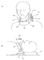
図8及び図9に、本発明に係る気道確保装置の第3実施の形態を示す。本実施の形態に係る気道確保装置61は、口を閉じて顎先を挙上させる機構62と、さらに好ましくは頭部を後屈させる機構63とを有した装着体64を備えている。この装着体64は、患者の頚部67に余裕を持って着脱可能に装着できる首輪状本体(いわゆるカラー状本体)68を有し、この首輪状本体68の頚部67を挟む前後に、それぞれ機構62を構成する下顎挙上用のエアバック69、及び機構63を構成する頭部後屈用のエアバック70を配置して構成される。このエアバック69及び70は、首輪状本体68に一体に取り付けた構成とすることが好ましいが、首輪状本体68と別体に構成し、あるいは首輪状本体68対して着脱可能に構成し、使用時に首輪状本体68に配置、あるいは取り付けするようになすことも可能である。
エアバック69及び70は、空気により膨張、収縮する袋状体により構成される。この装着体64のエアバック69、70は、例えば、鼾あるいは無呼吸・低呼吸などの異常の検知に基いて駆動させることができる。
[Third Embodiment]
8 and 9 show a third embodiment of the airway securing device according to the present invention. The
The
首輪状本体68は、例えば軽量の発砲樹脂材料で形成され、かつ一体成形された連結部を中心に開閉可能に形成される。開閉端部には、例えば2つのマジックテープ(登録商標)72が取り付けられ、マジックテープ(登録商標)72の接着力で首輪状本体68が閉じた状態に固定される。
The collar-shaped
エアバック69は、頚部67の前側に位置するように、首輪状本体68の下顎に対向する前方上面部に一体に取り付けられ、エアバック70は、首67の後側に位置するように、首輪状本体68の後方背面部に一体に取り付けられる。両エアバック69及び70は、前述したと同様に、空気で満たされて膨張し、空気の排出で収縮する袋状体で形成される。
The
この装着体64は、睡眠時に異常を検知する機構と組み合わせて使用される。異常を検知する機構としては、無呼吸・低呼吸を検知する手段、鼾の発生を検知する手段のうち、いずれか1つ以上を一体に有する。例えば、この異常を検知する機構として、マイクロホン、センサ、その他の鼾や無呼吸・低呼吸を検知する検知手段を用いることができる。マイクロホンを用いるときは、首輪状本体68に一体に搭載することができる。前述したセンサなどは、装着体64と別体に配置することになる。
The wearing
さらに、本実施の形態の気道確保装置61は、図示しないが、第1実施の形態で説明したと同様の、顎先を挙上させる機構62であるエアバック69、頭部を後屈させる機構63であるエアバック70を駆動制御するための制御装置14と、制御装置14の指令でエアバック69、70を駆動する駆動装置15とを備える。
Furthermore, although not shown, the
次に、第3実施の形態の気道確保装置61の動作を説明する。気道確保装置61は、図8及び図9に示すように、患者が寝た状態で、頚部67に装着体64の装着体首輪状本体68が余裕を持って装着されるように、配置される。
Next, the operation of the
図8A、Bは、正常時の状態を示す。患者は、頭部を枕73上に載せて仰向けに寝る。このとき、両エアバック69及び70は収縮状態にある。また、枕73の高さ分、頚部67の背面のエアバック70とベッドとの間に空間ができる。この空間はエアバック70の膨張を容易にする。
8A and 8B show a normal state. The patient puts his head on the
次に、無呼吸・低呼吸あるいは鼾をかいた状態になると、検知手段から異常検知に基き、制御装置14から指令が駆動装置15に伝達され、及び駆動装置15が駆動を開始し、最初に駆動装置15から空気がエアバック69に送られる。これにより、図9A、Bに示すように、下顎に対向しているエアバック69が膨張し、患者の口が閉じられ顎先が挙上される。口が閉じられ、顎先が挙上されることにより、患者の気道スペースが広がり、気道が確保され、呼吸が正常に戻る。
Next, when apnea / hypopnea or snoring is reached, a command is transmitted from the
さらに、エアバック69が膨張した後、駆動装置15から頚部背面のエアバック70に空気が送られ、エアバック70が膨張する。このエアバック70の膨張で頭部が後屈する。頭部後屈により、更に患者の気道スペースが広がり、確実に気道が確保され、正常な呼吸に戻る。
Furthermore, after the
第3実施の形態に係る気道確保装置61によれば、就眠中の無呼吸・低呼吸、あるいは鼾の検知に基いて、エアバック69,70が膨張し、下顎挙上動作がなされ、さらに頭部後屈動作がなされるので、確実に気道を確保することができる。また、装着体64が首輪状に構成されているので、就眠中の体位の自由が得られ、不快感を与えることがない。さらに、装着体64が、首輪状本体と2つのエアバック69及び70を有する簡単な構造であるので、気道確保装置61をよりコンパクトに構成することができる。
According to the
上例では、下顎挙上用のエアバック69及び頭部後屈用エアバック70を有した構成としたが、頭部後屈用エアバック70を省略し、下顎挙上用のエアバック69のみを有した構成とすることもできる。あるいは、下顎挙上用エアバック69を省略し、頭部後屈用のエアバック70のみを有した構成とすることもできる。
In the above example, the configuration includes the
上述の本発明の実施の形態における気道確保装置は、鼾の解消あるいは無呼吸症候群患者の呼吸正常化を目的とするものである。図1、図3、図6及び図7、図8及び図9で示す実施の形態では、無呼吸症候群の治療、症状の改善に適用することができる。また、図6及び図7、図8及び図9で示す実施の形態では、通常の鼾の解消に適用することができる。 The airway securing device in the above-described embodiment of the present invention is intended to eliminate hemorrhoids or normalize breathing in patients with apnea syndrome. The embodiments shown in FIGS. 1, 3, 6 and 7, 8 and 9 can be applied to treatment of apnea syndrome and improvement of symptoms. Moreover, in embodiment shown in FIG.6 and FIG.7, FIG.8 and FIG. 9, it can apply to cancellation of a normal wrinkle.
さらに、上述の第1、第2、第3実施の形態などの気道確保装置1、21、61は、手術中の麻酔による入眠時の気道を確保するための気道確保装置にも適用することができる。
Furthermore, the
第1、第2、第3実施の形態に係る気道確保装置は、いわゆるエアバック方式であるので、重量(軽量であること)やコンパクトさ、柔軟性などで優れている。 Since the airway securing device according to the first, second, and third embodiments is a so-called airbag system, it is excellent in weight (being light), compactness, flexibility, and the like.
[第4実施の形態]
図10及び図11に、本発明に係る気道確保装置の第4実施の形態を説明する。本実施の形態に係る気道確保装置31は、両端部にて軸32により開閉可能に軸支された下側フレーム33及び上側フレーム34と、上側フレーム34の両端に固定された第1プーリ35及び第2プーリ36と、両プーリ35及び36に巻回して上側フレーム34を開閉させる駆動伝達体37を有している。また、下側フレーム33には、頚部に対して下側フレーム33及び上側フレーム34が前後に移動しないように、このフレーム33,34に支持フレーム37が装着される。さらに、本気道確保装置31は、制御装置39及び上記ワイヤ37駆動させる駆動装置40を備えている。
[Fourth embodiment]
10 and 11, the fourth embodiment of the airway securing device according to the present invention will be described. The
下側フレーム33は、前襟部分、あるいは裸体状態であれば前襟部分に相当する胸部上方に接触するフレームであり、上側フレーム34は、下顎に接触するフレームである。下側フレーム33及び上側フレーム34は、装着時に頚部を逃げる形状、本例では略U字形状に形成される。そして、略U字形状の上側フレーム34の両端部に軸32が固定的に設けられ、この軸32に略U字形状の下側フレーム33に両端部が回動可能に支軸される。上側フレーム34の両端部は、下側フレーム33の内側に配置される。上側フレーム34の下顎に接触する表面には、下顎を傷つけないように柔軟シート50が被着形成される(図13、図14参照)。
The
第1プーリ35は、上側フレーム34の一端部に設けられた一方の軸32に、圧入などにより固定して配置される。第2プーリ36は、上側フレーム34の他端部に設けられた他方の軸32に、圧入などにより固定して配置される。また、U字形状をなす下側フレーム33の両腕部33a及び33bの内面に、第1プーリ35、第2プーリ36にそれぞれ近接して、両プーリ35,36より小さい径の小プーリ43,44が設けられる。
The
駆動伝達体37としては、ワイヤ51と糸状体(以下、駆動伝達糸という)52とにより構成される。これらワイヤ51及び駆動伝達糸52は、一部がチューブ内に挿通された構成を有し、例えばボーデンケーブル41aおよび41bを用いることができる。ワイヤ51は、チューブと共に下側フレーム33の外部より内側に挿入され、下側フレーム33の腕部33bの内面に沿うように配置される。ボーデンケーブル41aのチューブから出たワイヤ51の先端は、緩衝弾性体、本例では緩衝バネ53を介して駆動伝達糸52に連結される。
The
駆動伝達糸52は、第2プーリ36の下から入り、上側に回り込むように、第2プーリ36に巻回され、プーリ上側から出て小プーリ44の下側に案内されるように下側フレーム33の内面に沿い、ボーデンケーブル41bのチューブ内を挿通して一方の腕部33aに配置される。駆動伝達糸52の途中部分52Bは第2プーリ36に巻回される途中で同プールに固定される(図16A参照)。チューブから出た駆動伝達糸52は、一方の腕部33aに設けられた小プーリ43の上側に案内されながら第1プーリ35に巻回される。駆動伝達糸52は、第1プーリ35の下から入り上側に回り込むようにして第1プーリ35に巻回され、その先端(駆動伝達糸の一端部)52Aが第1プーリ35に固定される(図16B参照)。
The
下側フレーム33の内面に配置されたボーデンケーブル41bのチューブ端のそれぞれは、下側フレーム33の内面に取り付け具54を介して固定される。
Each of the tube ends of the
下側フレーム33と上側フレーム34との間に差し渡って、例えば下側フレーム33の他方の腕部33bの内面と、上側フレーム34の他方の腕部34bの内面との間に差し渡って、上側フレーム34を常時、下側フレーム33に対し閉じる方向作用する弾性体、本例では復元力生成用ゴム部材46が取り付けられる。
Between the
支持フレーム38は、U字形状に形成され、下側フレーム33に着脱可能に取り付けられる。例えば図12に示すように、支持フレーム38は、下側フレーム33の両端部を挟むように配置され、その両腕部38a,38bの先端に溝部55を有して形成される。この溝部55は、軸32を回転できるように、かつ弾性的に挟持できるように、一部ひさし部55aを有して形成される。支持フレーム38は、溝部55を下から軸32に嵌め込むことにより、下側フレーム33に取り付けられる。また、支持フレーム38は、下側へ引き下ろすことにより、下側フレームから取り外すことができる。
The
一方、駆動装置40は、例えば電気モータなどの電動式の駆動装置で構成される。電気モータを用いるときは、この電気モータに連結された駆動伝達部にワイヤ51の端部を連結し、例えば電機モータの回転方向を制御することにより、ワイヤ51の押し引き動作が行える。
On the other hand, the driving
制御装置39は、気道確保を必要とする情報(信号)、あるいは正常状態の情報(信号)の入力に基いて、駆動装置40へ所要の駆動用信号を出力する。例えば、前述したセンサ4で得られた信号を基に、気道確保の有無を判定し、制御装置39から駆動装置40へ指令を送るようになされる。
The
例えば、鼾あるいは無呼吸症候群の治療では、センサ4で得られた信号を基に、睡眠中の鼾あるいは無呼吸・低呼吸の有無を判定し、制御装置39から駆動装置40へ指令を送るようになされる。また、手術中の麻酔による入眠時における気道確保の場合には、医師や看護婦が気道確保開始のスイッチを入れると、制御装置39は駆動装置40へ指令を送り、気道確保動作を行う。センサ4で得られた信号を基に気道閉塞の無いことを確認しながら停止のスイッチが入るまで気道確保動作を継続する。万が一、途中で呼吸に異常が見られた場合には、医師に警告音等でその旨を伝える。
For example, in the treatment of epilepsy or apnea syndrome, the presence or absence of epilepsy or apnea / hypopnea during sleep is determined based on the signal obtained by the
次に、第4実施の形態の気道確保装置31の動作を説明する。気道確保装置31は、図13及び図14に示すように、患者が寝た状態で、前襟部分にその両フレーム33及び34の開口側が頚部に対向するように装着される。すなわち、装置31は、下側フレーム33が前襟部分に接触し、上側フレーム34が下顎に対向して装着される。裸体に装着するときは、装置31は、前襟部分に相当する胸部上方に装着される。
Next, the operation of the
図13は、通常時の装着状態を示す。通常時、装置31は、図13に示すように、上側フレーム34が下側フレーム33に対して閉じた状態になっている。通常時は、図10において、駆動装置40からの駆動力により、ボーデンケーブル41aのワイヤ51が矢印A方向に押し出される。このワイヤ51の駆動により、第2プーリ36に巻回された駆動伝達用糸52が緩められ、さらに第1プーリ35に巻回された駆動伝達糸52が緩められる。同時に、図16A、Bに示すように、復元力生成用ゴム部材46がその復元力F1により縮むことにより、上側フレーム34が矢印A1方向に回動し閉じられる。このとき、上側フレーム34の閉じる方向の回動と共に、上側フレーム34と一体の第2プーリ36、第1プーリ35も同方向、(矢印A1方向)に回転し、駆動伝達糸52が緊張状態となる。図15は、上側フレーム34が閉じられた状態を示している。
FIG. 13 shows a normal wearing state. Normally, the
図14は、上側フレーム34が下側フレーム33に対して開らかれ、下顎挙上動作が行われた状態を示す。下顎挙上動作時は、図10において、駆動装置40からの駆動力により、ワイヤ51が矢印B方向に引かれる。このワイヤ51の駆動により、図18A、Bに示すように、第2プーリ36に巻回された駆動伝達用糸52が第2プーリ36を矢印B1方向に回転させる。この回転力は、下側フレーム33内のボーデンケーブル41で2つの小プーリ44、43を介して第1プーリ35に伝達され、第1プーリ35を矢印B1方向に回転させる。この両プーリ35、36の回転に伴い、上側フレーム34が下側フレーム33に対して開かれる。このとき、復元力生成用ゴム部材46が復元力F1に抗して伸ばされ、上側フレーム34は開状態となる。この上側フレーム34は、患者の下顎に接触しながら開くことにより、顎先が挙上されると共に、頭部が後屈し、気道スペースが広がり、気道を確保することができる。すなわち、上側フレームが開くことで、下顎挙上動作と共に、頭部後屈動作が行われる。図17は、上側フレーム34が開かれた状態を示している。
FIG. 14 shows a state in which the
緩衝バネ53は、快適な下顎挙上動作の実現と安全性の確保を目的としたバネである。緩衝バネ53を介挿することで上側フレーム34の開閉に弾力を持たせることができる。因みに、ワイヤ51と駆動伝達用糸52との間に緩衝バネ53がないと、ワイヤ51の駆動量の分だけ確実に顎が押し上げられる。しかし、何らかの理由でそれ以上顎を上げられない事態が生じたとき、過度な力を受けて痛みを生ずる可能性がある。本実施の形態では、緩衝バネ53を介することでクッションが働いて柔らかく力が作用し、心地よく下顎挙上がなされる。万一、顎を上げられない事態が発生しても、緩衝バネ53が生じさせうる復元力以上の力はかからず、安全である。
The
第4実施の形態に係る気道確保装置31によれば、外部からの1本のボーデンケーブル41の操作で、上下側フレーム34、34の左右両方の関節部に相当する端部が第1、第2プーリ35、36を介して同時に駆動される。従って、気道確保装置31は、左右バランスよく均等に力を発揮させて上側フレーム34を安定させて開閉動作を行うことができ、安定した下顎挙上動作、及び頭部後屈動作を実現し、気道確保を行うことができる。
According to the
第4実施の形態の気道確保装置31は、支持フレーム38を省略するなどのスリム化を図り、例えばパジャマの胸元にマジックテープ(登録商標)で下側フレーム33を固定するなどすれば、就眠体位を選ばず、また装着にも不快感なく使用できる。
The
第4実施の形態の気道確保装置31は、気道閉塞を検知して電動駆動で気道を確保する、いわゆる電動式であるので、動作速度が速く、また製作し易い利点を有する。この気道確保装置31は、下顎挙上と頭部後屈の両方の動作を実現するには、やや大きな駆動力を必要とする。一方、患者によっては、頭部後屈は必要なく、下顎挙上だけでも気道確保に十分な効果を発揮する場合がある。その場合は、微小な駆動力で済み、その結果、非常にコンパクトで安価な構成で気道確保装置を実現できる。
Since the
第4実施の形態の気道確保装置31は、鼾および無呼吸症治療装置として用いることができる。また、この気道確保装置31は、手術中の麻酔による入眠時における気道確保にも適用することができる。
The
1、21・・鼾あるいは無呼吸症候群の気道確保装置、2・・身体、3・・装着体、4・・センサ、5・・口を閉じて顎先を挙上させる機構、6・・頭部を後屈させる機構、7、8、27・・袋状体、11・・腹部ベルト型のセンサ部、12・・胸部ベルト型のセンサ部、14・・制御装置、15・・駆動装置、16・・枕、28・・マイクロホン、31・・気道確保装置、32・・軸、33・・下側フレーム、34・・上側フレーム、35,36・・プーリ、37・・駆動伝達体、38・・支持フレーム、39・・制御装置、40・・駆動装置、41・・ボーデンケーブル、43、44・・小プーリ、46・・復元力生成用ゴム、50・・柔軟シート、51・・ワイヤ、52・・駆動伝達用糸、53・・緩衝バネ、61・・気道確保装置、62・・口を閉じて顎先を挙上させる機構、63・・頭部を後屈させる機構、64・・装着体、68・・首輪状本体、69・・下顎挙上用のエアバック、70・・頭部後屈用のエアバック
1,21 .... Airway securing device for epilepsy or
Claims (5)
前記装着体が、
前記就眠者の下顎と胸部の上方部位との間に配置され、当該就眠者の口を閉じて顎先を挙上させる第1の機構と、
前記就眠者の後頭部と頸部の下方部位との間に配置され、当該就眠者の頭部を後屈させる第2の機構とを備え、
前記第1及び第2の機構は、各々が空気室を有して空気により膨張、収縮する袋状体で形成され、
前記就眠者の仰臥姿勢において、前記第1の機構では、当該機構の前記空気室に空気が供給されると膨張して当該機構の前記袋状体が就眠者の顎に向かって隆起し、
前記第2の機構では、当該機構の前記空気室に空気が供給されると膨張して当該機構の前記袋状体が就眠者の肩部あるいは胸部を持ち上げる
ことを特徴とする気道確保装置。 An airway securing device that secures an airway by having a mounting body that can be worn outside the body of a sleeping person,
The wearing body is
A first mechanism disposed between the lower jaw of the sleeper and an upper part of the chest, and closing the sleeper's mouth and raising the chin tip;
A second mechanism disposed between the back of the sleeping person and the lower part of the neck, the second mechanism for bending the sleeping person's head backward ,
The first and second mechanisms are each formed of a bag-like body that has an air chamber and expands and contracts by air ,
In the sleeping person's supine posture, in the first mechanism, when air is supplied to the air chamber of the mechanism, the bag-like body of the mechanism rises toward the sleeping person's jaw,
In the second mechanism, the airway securing device, characterized in that the bag-like body of the mechanism expands and air is supplied to the air chamber of the mechanism Ru lifts the shoulder or chest sleeping person.
ことを特徴とする請求項1に記載の気道確保装置。 The airway securing according to claim 1, wherein the wearing body having the first mechanism for raising the chin and the second mechanism for bending the head backward is formed by clothing. apparatus.
ことを特徴とする請求項1に記載の気道確保装置。 The airway securing device according to claim 1, wherein the mounting body having a first mechanism for raising the chin and a second mechanism for bending the head backward has a collar-like body.
前記顎先を挙上させる第1の機構及び前記頭部を後屈させる第2の機構を駆動する駆動装置と、
前記異常を検知する機構の出力に基づいて前記第1の機構及び、前記第2の機構を駆動するように前記駆動装置を制御する制御装置とを有している
ことを特徴とする請求項1乃至3に記載の気道確保装置。 Provided with a mechanism for detecting abnormalities during sleep in the wearing body,
A driving device for driving a first mechanism for raising the jaw tip and a second mechanism for bending the head;
The control device that controls the drive device to drive the first mechanism and the second mechanism based on an output of a mechanism that detects the abnormality. The airway securing device of thru | or 3.
ことを特徴とする請求項4に記載の気道確保装置。 The airway securing device according to claim 4, wherein the mechanism for detecting an abnormality includes at least one of a means for detecting apnea / hypopnea and a means for detecting occurrence of sputum.
Priority Applications (5)
| Application Number | Priority Date | Filing Date | Title |
|---|---|---|---|
| JP2008235737A JP5263765B2 (en) | 2007-11-22 | 2008-09-12 | Airway securing device |
| US12/741,902 US20100224198A1 (en) | 2007-11-22 | 2008-11-18 | Airway-opening device |
| PCT/JP2008/070891 WO2009066645A1 (en) | 2007-11-22 | 2008-11-18 | Airway-opening device |
| CN2008801173246A CN101883544B (en) | 2007-11-22 | 2008-11-18 | Airway-opening device |
| EP08851084A EP2213265A4 (en) | 2007-11-22 | 2008-11-18 | Airway-opening device |
Applications Claiming Priority (3)
| Application Number | Priority Date | Filing Date | Title |
|---|---|---|---|
| JP2007303615 | 2007-11-22 | ||
| JP2007303615 | 2007-11-22 | ||
| JP2008235737A JP5263765B2 (en) | 2007-11-22 | 2008-09-12 | Airway securing device |
Publications (3)
| Publication Number | Publication Date |
|---|---|
| JP2009142642A JP2009142642A (en) | 2009-07-02 |
| JP2009142642A5 JP2009142642A5 (en) | 2010-03-25 |
| JP5263765B2 true JP5263765B2 (en) | 2013-08-14 |
Family
ID=40667467
Family Applications (1)
| Application Number | Title | Priority Date | Filing Date |
|---|---|---|---|
| JP2008235737A Expired - Fee Related JP5263765B2 (en) | 2007-11-22 | 2008-09-12 | Airway securing device |
Country Status (5)
| Country | Link |
|---|---|
| US (1) | US20100224198A1 (en) |
| EP (1) | EP2213265A4 (en) |
| JP (1) | JP5263765B2 (en) |
| CN (1) | CN101883544B (en) |
| WO (1) | WO2009066645A1 (en) |
Families Citing this family (18)
| Publication number | Priority date | Publication date | Assignee | Title |
|---|---|---|---|---|
| JP5798929B2 (en) * | 2009-12-21 | 2015-10-21 | 扶桑薬品工業株式会社 | Airway dilator and airway dilator unit having the same |
| US10856800B2 (en) * | 2012-06-08 | 2020-12-08 | United States Government As Represented By The Department Of Veterans Affairs | Portable polysomnography apparatus and system |
| JP2015522327A (en) * | 2012-06-11 | 2015-08-06 | コーニンクレッカ フィリップス エヌ ヴェ | Neck extension device and method of use |
| WO2014030737A1 (en) * | 2012-08-23 | 2014-02-27 | 国立大学法人長崎大学 | Airway-securing device |
| DE102013001077A1 (en) * | 2013-01-23 | 2014-07-24 | Sissel International GmbH | pillow |
| KR101479025B1 (en) | 2013-06-21 | 2015-01-05 | 경희대학교 산학협력단 | Sleeping assist appliance for preventing snoring and sleep apnea |
| JP2015116367A (en) * | 2013-12-19 | 2015-06-25 | 重人 下山 | Bedding device, bedding device control method and program |
| CN104224475B (en) * | 2014-09-10 | 2017-04-05 | 张瑞华 | Continue airway open pillow |
| WO2016138667A1 (en) * | 2015-03-05 | 2016-09-09 | 莱镁医疗器材股份有限公司 | System and method for increasing patency degree of upper respiratory tract |
| US10335310B2 (en) | 2015-03-16 | 2019-07-02 | Aliasghar Hariri | Apparatuses and methods for disrupting and preventing snore |
| US10258319B2 (en) | 2015-05-18 | 2019-04-16 | Richard L. Arden | Airway assist device and method |
| US10010313B2 (en) | 2015-05-18 | 2018-07-03 | Richard L. Arden | Mandibular subluxation device and method |
| US10342526B2 (en) | 2015-07-01 | 2019-07-09 | Richard L. Arden | Airway assist device and method |
| US11065142B2 (en) * | 2016-06-17 | 2021-07-20 | Quazar Ekb Llc | Orthopedic devices and systems integrated with controlling devices |
| EP3496074A4 (en) * | 2016-08-03 | 2020-03-25 | Micoto Technology Inc. | Medical simulator |
| US11497678B2 (en) * | 2019-09-18 | 2022-11-15 | Sifferlin Conceptual Designs Company, LLC | System and method for airway management |
| JP7280580B2 (en) * | 2019-09-11 | 2023-05-24 | 学校法人 中央大学 | Measuring device and measuring method |
| IT202100028325A1 (en) * | 2021-11-08 | 2023-05-08 | Andrea Marco Minetti | INTERACTIVE SYSTEM FOR THE TREATMENT OF OBSTRUCTIVE SLEEP APNEA SYNDROME. |
Family Cites Families (27)
| Publication number | Priority date | Publication date | Assignee | Title |
|---|---|---|---|---|
| US188752A (en) * | 1877-03-27 | Improvement in rotary engines | ||
| US3312985A (en) * | 1966-07-05 | 1967-04-11 | Invalift Corp | Invalid bed with lifting mechanism |
| GB2226239B (en) * | 1988-12-21 | 1991-09-18 | Porta Products Limited | A sleeping aid |
| JP2606811B2 (en) * | 1993-11-16 | 1997-05-07 | アダプトゲン製薬株式会社 | Snoring prevention equipment |
| US5752927A (en) * | 1995-12-29 | 1998-05-19 | Rogachevsky; Richard J. | Inflatable cervical traction device |
| JPH1085108A (en) * | 1996-09-13 | 1998-04-07 | Toshio Nishino | Waving air permiable pillow |
| NZ514687A (en) * | 1999-04-09 | 2003-08-29 | Archibald Ian Jeremy Brain | Disposable laryngeal mask airway device |
| US6287290B1 (en) * | 1999-07-02 | 2001-09-11 | Pulmonx | Methods, systems, and kits for lung volume reduction |
| US7204250B1 (en) * | 1999-12-16 | 2007-04-17 | Compumedics Limited | Bio-mask |
| JP4625600B2 (en) * | 2001-09-27 | 2011-02-02 | 医療法人社団松田歯科医院 | Preventive measures such as sleep apnea |
| US20030188752A1 (en) * | 2002-04-03 | 2003-10-09 | Zirafi Christine M. | Device and method for maintaining an airway in an open condition useful for anesthetized or other breathing difficulty states |
| US6779526B2 (en) * | 2002-08-15 | 2004-08-24 | Yasuo Kawamura | Apnea prevention gear |
| JP2004089662A (en) * | 2002-09-03 | 2004-03-25 | Junichi Takesawa | Band for reinforcing muscular strength around mouth and neck |
| JP2004223026A (en) * | 2003-01-24 | 2004-08-12 | Hitachi Hometec Ltd | Pillow |
| JP4482302B2 (en) * | 2003-09-22 | 2010-06-16 | 博夫 小谷 | Sleep apnea syndrome treatment device |
| JP2005118241A (en) | 2003-10-16 | 2005-05-12 | Yoshi Sakurai | Snoring prevention apparatus |
| JP4530698B2 (en) * | 2004-03-25 | 2010-08-25 | 三洋電機株式会社 | Snoring suppression method and apparatus |
| JP2006101934A (en) | 2004-09-30 | 2006-04-20 | Sanyo Electric Co Ltd | Snore prevention apparatus for pillow underlay and snore prevention method |
| JP2006231008A (en) | 2005-02-25 | 2006-09-07 | Yukio Ishiyama | Health pillow |
| JP2006280521A (en) * | 2005-03-31 | 2006-10-19 | Shuko Kono | Respiratory auxiliary device |
| US20080319277A1 (en) * | 2005-06-13 | 2008-12-25 | Braebon Medical Corporation | Sleep disorder monitoring and diagnostic system |
| CN100339060C (en) * | 2005-07-25 | 2007-09-26 | 谢榕衡 | Adjustable air-bag pillow with elastic head-band for elimination of snore |
| CN2827312Y (en) * | 2005-09-23 | 2006-10-18 | 谢榕衡 | Elastic traction type head hoop for eliminating snore |
| JP2007144076A (en) * | 2005-11-25 | 2007-06-14 | Tsukane Goto | Snore preventive implement |
| EP1844743A3 (en) * | 2006-04-14 | 2007-10-31 | Bio Sleep Med Co., Ltd. | Apparatus for preventing sleeping respiratory obstruction |
| US7900626B2 (en) * | 2006-04-17 | 2011-03-08 | Daly Robert W | Method and system for controlling breathing |
| US20090095309A1 (en) * | 2007-10-16 | 2009-04-16 | Derrick Steven J | Therapeutic/diagnostic external airway position support (EAPS) device and method |
-
2008
- 2008-09-12 JP JP2008235737A patent/JP5263765B2/en not_active Expired - Fee Related
- 2008-11-18 US US12/741,902 patent/US20100224198A1/en not_active Abandoned
- 2008-11-18 EP EP08851084A patent/EP2213265A4/en not_active Withdrawn
- 2008-11-18 WO PCT/JP2008/070891 patent/WO2009066645A1/en active Application Filing
- 2008-11-18 CN CN2008801173246A patent/CN101883544B/en not_active Expired - Fee Related
Also Published As
| Publication number | Publication date |
|---|---|
| JP2009142642A (en) | 2009-07-02 |
| EP2213265A1 (en) | 2010-08-04 |
| CN101883544B (en) | 2012-11-07 |
| WO2009066645A1 (en) | 2009-05-28 |
| CN101883544A (en) | 2010-11-10 |
| US20100224198A1 (en) | 2010-09-09 |
| EP2213265A4 (en) | 2011-10-05 |
Similar Documents
| Publication | Publication Date | Title |
|---|---|---|
| JP5263765B2 (en) | Airway securing device | |
| JP7071571B2 (en) | Adjustable headgear tubing for patient interface | |
| CN104302337B (en) | It is electrically excited Respiration assistance part | |
| JP7087207B2 (en) | Woven seal with air-assisted urging | |
| CN105726192B (en) | For improving the method and system of airway patency | |
| US10980963B1 (en) | Cloth respiratory mask | |
| JP4903208B2 (en) | Mask mounting device | |
| CN107683160A (en) | Textile patient interface | |
| JP2004533907A (en) | A respiratory treatment apparatus for keeping a non-artificial respiratory tract of a human body free of snoring noise and a method of using the respiratory treatment apparatus | |
| CN114466671A (en) | Fabric seal forming structure with multiple curvatures | |
| WO2010111749A1 (en) | Mask system | |
| JP2021525623A (en) | Headgear for patient interface | |
| CA2764277A1 (en) | Jaw thrust appliance | |
| JP2008173407A (en) | Apparatus for preventing snoring and snoring prevention method using the same | |
| JP2023504120A (en) | Adjustable headgear tubing for patient interface | |
| US8646453B2 (en) | Extendable airflow restriction system | |
| KR20100119249A (en) | A pillow for a snorer | |
| JP2022508663A (en) | Headgear tubing for patient interface | |
| US20110209708A1 (en) | Ventilation Interface Device | |
| CN113081426A (en) | Exoskeleton robot for expectoration assistance and control method | |
| JP6233847B2 (en) | Airway securing device | |
| JP5350967B2 (en) | Airway dilator | |
| CN111166551A (en) | Constraint glove | |
| US20120097157A1 (en) | Apparatus, systems, and methods for securing a breathing tube to an arm | |
| TW201242588A (en) | Automatic body standing auxiliary device |
Legal Events
| Date | Code | Title | Description |
|---|---|---|---|
| A521 | Request for written amendment filed |
Free format text: JAPANESE INTERMEDIATE CODE: A523 Effective date: 20100209 |
|
| A711 | Notification of change in applicant |
Free format text: JAPANESE INTERMEDIATE CODE: A711 Effective date: 20100323 |
|
| A521 | Request for written amendment filed |
Free format text: JAPANESE INTERMEDIATE CODE: A821 Effective date: 20100323 |
|
| A521 | Request for written amendment filed |
Free format text: JAPANESE INTERMEDIATE CODE: A523 Effective date: 20100427 |
|
| RD02 | Notification of acceptance of power of attorney |
Free format text: JAPANESE INTERMEDIATE CODE: A7422 Effective date: 20110415 |
|
| RD04 | Notification of resignation of power of attorney |
Free format text: JAPANESE INTERMEDIATE CODE: A7424 Effective date: 20110415 |
|
| A521 | Request for written amendment filed |
Free format text: JAPANESE INTERMEDIATE CODE: A523 Effective date: 20110506 |
|
| A621 | Written request for application examination |
Free format text: JAPANESE INTERMEDIATE CODE: A621 Effective date: 20110811 |
|
| A131 | Notification of reasons for refusal |
Free format text: JAPANESE INTERMEDIATE CODE: A131 Effective date: 20121016 |
|
| A521 | Request for written amendment filed |
Free format text: JAPANESE INTERMEDIATE CODE: A523 Effective date: 20121210 |
|
| A02 | Decision of refusal |
Free format text: JAPANESE INTERMEDIATE CODE: A02 Effective date: 20130115 |
|
| A521 | Request for written amendment filed |
Free format text: JAPANESE INTERMEDIATE CODE: A523 Effective date: 20130321 |
|
| A911 | Transfer to examiner for re-examination before appeal (zenchi) |
Free format text: JAPANESE INTERMEDIATE CODE: A911 Effective date: 20130328 |
|
| TRDD | Decision of grant or rejection written | ||
| A01 | Written decision to grant a patent or to grant a registration (utility model) |
Free format text: JAPANESE INTERMEDIATE CODE: A01 Effective date: 20130416 |
|
| A61 | First payment of annual fees (during grant procedure) |
Free format text: JAPANESE INTERMEDIATE CODE: A61 Effective date: 20130423 |
|
| R150 | Certificate of patent or registration of utility model |
Ref document number: 5263765 Country of ref document: JP Free format text: JAPANESE INTERMEDIATE CODE: R150 Free format text: JAPANESE INTERMEDIATE CODE: R150 |
|
| R250 | Receipt of annual fees |
Free format text: JAPANESE INTERMEDIATE CODE: R250 |
|
| R250 | Receipt of annual fees |
Free format text: JAPANESE INTERMEDIATE CODE: R250 |
|
| R250 | Receipt of annual fees |
Free format text: JAPANESE INTERMEDIATE CODE: R250 |
|
| LAPS | Cancellation because of no payment of annual fees |