JP5259076B2 - Ultrasonic transceiver and scanning sonar - Google Patents
Ultrasonic transceiver and scanning sonar Download PDFInfo
- Publication number
- JP5259076B2 JP5259076B2 JP2006325504A JP2006325504A JP5259076B2 JP 5259076 B2 JP5259076 B2 JP 5259076B2 JP 2006325504 A JP2006325504 A JP 2006325504A JP 2006325504 A JP2006325504 A JP 2006325504A JP 5259076 B2 JP5259076 B2 JP 5259076B2
- Authority
- JP
- Japan
- Prior art keywords
- transmission
- reception
- azimuth
- frequency
- signal
- Prior art date
- Legal status (The legal status is an assumption and is not a legal conclusion. Google has not performed a legal analysis and makes no representation as to the accuracy of the status listed.)
- Expired - Fee Related
Links
Images


Landscapes
- Measurement Of Velocity Or Position Using Acoustic Or Ultrasonic Waves (AREA)
Abstract
Description
この発明は、超音波の送受信によって水中等を探知する超音波送受信装置およびスキャニングソナーに関するものである。 The present invention relates to an ultrasonic transmission / reception apparatus and scanning sonar that detect underwater or the like by transmission / reception of ultrasonic waves.
従来、水中探知を行うためにスキャニングソナーが用いられている。スキャニングソナーは、周囲の全方位の物標を探知するために、ほぼ円筒形や球形のトランスデューサを備えている。送信時にはトランスデューサの各振動子の駆動によって、全周に向けて所定のチルト角をもって(傘型の)超音波の送信ビームを形成する。または所定の開口を設定し、その開口内の振動子を位相制御するとともに駆動することによって所定方位に向けて超音波の送信ビームを形成し、その送信ビームの方位を全周囲に亘ってスキャンするように構成している。受信時には、所定の開口を設定し、その開口内の振動子による受信信号を位相合成することによって受信ビームを形成する。 Conventionally, scanning sonar is used for underwater detection. Scanning sonar includes a substantially cylindrical or spherical transducer to detect surrounding omnidirectional targets. At the time of transmission, by driving each transducer of the transducer, an ultrasonic transmission beam is formed with a predetermined tilt angle toward the entire circumference. Alternatively, a predetermined aperture is set, and the transducer in the aperture is phase-controlled and driven to form an ultrasonic transmission beam in a predetermined direction, and the direction of the transmission beam is scanned over the entire circumference. It is configured as follows. At the time of reception, a predetermined aperture is set, and a reception beam is formed by synthesizing the phase of the reception signal from the transducer in the aperture.
このことによって、垂直方向の指向性を所定角度に絞った、所定ティルト角の傘型の送信ビームを形成し、その傘型の送信ビーム内の全方位に亘る探知を行う。 Thus, an umbrella-shaped transmission beam having a predetermined tilt angle with the directivity in the vertical direction narrowed to a predetermined angle is formed, and detection is performed in all directions within the umbrella-shaped transmission beam.
しかし、上記構成のスキャニングソナーにおいては、トランスデューサが複数の超音波振動子を等間隔に配列したものであるので、その構造上、グレーティングローブやサイドローブが生じる。 However, in the scanning sonar having the above-described configuration, since the transducer has a plurality of ultrasonic transducers arranged at equal intervals, a grating lobe and a side lobe are generated due to its structure.
このようなグレーティングローブやサイドローブを有する送信ビームまたは受信ビームを方位方向に順次変化させて探査を行うと、メインローブが実在する物標とは異なった方向を向いている状態でグレーティングローブまたはサイドローブがその物標からの反射波を受けることにより、偽像が生じる。 When a search is performed by sequentially changing the transmission beam or reception beam having such a grating lobe or side lobe in the azimuth direction, the grating lobe or side in a state where the main lobe is directed in a direction different from the actual target. When the lobe receives the reflected wave from the target, a false image is generated.
上記のグレーティングローブを低減させるためには、超音波振動子の振動子間ピッチを狭くする方法がある程度有効である。しかし、振動子数が増えると、それを駆動する駆動回路、駆動のための制御回路、受信回路、さらには受信信号を処理する回路等が比例して増大するため、ハードウエアが肥大化し、大幅なコストアップにつながる。 In order to reduce the grating lobes described above, a method of narrowing the pitch between the ultrasonic transducers is effective to some extent. However, as the number of vibrators increases, the drive circuit that drives them, the control circuit for driving, the receiving circuit, and the circuit that processes the received signal, etc., increase proportionally, which increases the size of the hardware. Lead to significant cost increase.
そこで、本願出願人は特許文献1にて、方位に応じて超音波の周波数に違いをもたせることによって、上述の問題を解消した発明について出願している。
Therefore, the applicant of the present application has applied for an invention in which the above-mentioned problems are solved by making a difference in the frequency of the ultrasonic wave according to the orientation in
上記特許文献1では、グレーティングローブやサイドローブによる偽像を低減する方法として、方位別に周波数の異なったバースト波を送信し、受信時にビーム方位別の帯域制限を行う方位別周波数送受信法(本発明ではDFM(Directional Frequency Modulation)送信法という。)が用いられている。
In the
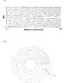
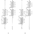
図1は上記DFM送信法の1つの例であるDFM−FM送信法を図示したものである。(A)はトランスデューサ上の各振動子の駆動周波数を示している。その横軸はトランスデューサ上の基準方位からの振動子の方位方向の位置(以下、「素子方位角」という。)、縦軸は基準方位(0°)におけるバースト波の開始タイミングを0とする経過時間である。ここで、Tはバースト波の持続時間、Fwは0°〜360°の範囲でのバースト波の中心周波数の変化幅(方位別周波数掃引幅)、Bは1つのバースト波内での周波数掃引幅である。(B)は送信信号の波面の例を示している。この図において、円形で示す部分がトランスデューサ、その内部で扇状に示す角度範囲が送信開口である。このように送信開口を方位方向に順次移動させながら、送信周波数を変化させる。 FIG. 1 illustrates a DFM-FM transmission method which is an example of the DFM transmission method. (A) shows the drive frequency of each transducer on the transducer. The horizontal axis represents the position in the azimuth direction of the vibrator from the reference azimuth on the transducer (hereinafter referred to as “element azimuth angle”), and the vertical axis represents the time when the burst wave start timing in the reference azimuth (0 °) is zero. It's time. Here, T is the duration of the burst wave, Fw is the change width of the center frequency of the burst wave in the range of 0 ° to 360 ° (frequency sweep width by direction), and B is the frequency sweep width within one burst wave. It is. (B) shows an example of the wavefront of the transmission signal. In this figure, the portion indicated by a circle is a transducer, and the angular range indicated by a fan inside is a transmission aperture. In this way, the transmission frequency is changed while sequentially moving the transmission aperture in the azimuth direction.
図2は上記DFM送信法の別の例であるDFM−CW送信法を図示したものである。(A)はトランスデューサ上の各振動子の駆動周波数を示している。横軸は基準方位からの素子方位角、縦軸はバースト波の開始タイミングを0とする経過時間である。(B)はトランスデューサから送信される送信信号の波面の例を示している。中心の円はトランスデューサ、このトランスデューサと同心円状にある円Hは送信後所定時間経過後の波面である。素子方位角が0から増す程、送信信号の周波数は次第に高くなる関係にある。 FIG. 2 illustrates a DFM-CW transmission method, which is another example of the DFM transmission method. (A) shows the drive frequency of each transducer on the transducer. The horizontal axis represents the element azimuth angle from the reference azimuth, and the vertical axis represents the elapsed time when the burst wave start timing is zero. (B) shows an example of the wavefront of the transmission signal transmitted from the transducer. A circle at the center is a transducer, and a circle H concentrically with the transducer is a wavefront after a predetermined time has elapsed after transmission. As the element azimuth angle increases from 0, the frequency of the transmission signal gradually increases.
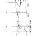
図3は、基準方位からの素子方位角に対するバースト波の中心周波数の関係と、所定方位における受信ビームについて示している。
図3の(a)は船首を基準方位とする素子方位角を横軸にとり、バースト波の送信周波数を縦軸にとったものである。ここで、fcは船首方位へ送信するバースト波の周波数、BDFMはバースト波の中心周波数の変化幅(方位別周波数掃引幅)である。
FIG. 3 shows the relationship of the center frequency of the burst wave with respect to the element azimuth angle from the reference azimuth and the received beam in a predetermined azimuth.
FIG. 3A shows the element azimuth with the bow as the reference azimuth on the horizontal axis and the burst wave transmission frequency on the vertical axis. Here, fc is the frequency of the burst wave transmitted to the heading, and B DFM is the change width (frequency sweep width for each direction) of the center frequency of the burst wave.
また(b)は、素子方位角θx方向に受信ビームを形成した時の、そのθxを中心とする所定方位範囲の指向特性を表している。このように素子方位角θxを中心として多くのグレーティングローブ(GL)およびサイドローブが生じる。 Further, (b) represents the directivity characteristics in a predetermined azimuth range centered on θx when a reception beam is formed in the element azimuth angle θx direction. Thus, many grating lobes (GL) and side lobes are generated around the element azimuth angle θx.
これを、(c)に示すような特性の、方位ごとの周波数フィルタリングを行うことにより、(d)に示すようにグレーティングローブやサイドローブが抑圧されて、目的とする方位からの受信信号が得られる。 By performing frequency filtering for each direction with the characteristics shown in (c), the grating lobes and side lobes are suppressed as shown in (d), and a received signal from the target direction is obtained. It is done.
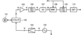
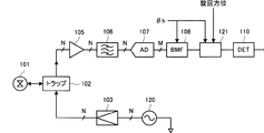
図4は上記DFM送信法を適用した超音波送受信装置の構成をブロック図として表したものである。発振回路104はトランスデューサ101の各振動子を駆動する駆動信号を生成し、増幅回路103がそれを増幅し、トラップ102を介してトランスデューサ101の各振動子を駆動する。
FIG. 4 is a block diagram showing the configuration of an ultrasonic transmission / reception apparatus to which the DFM transmission method is applied. The
プリアンプ105は受信ビームを形成すべき方向に向く所定の広がりをもつ開口内の複数の振動子の受信信号を増幅し、プリフィルタ106は不要な雑音周波数成分を除去する。A/Dコンバータ107は各信号をディジタルデータへ変換し、ビームフォーマ108は受信すべき方位θhを向く鋭い受信ビームを形成する。バンドパスフィルタ109は受信ビームの方位θhに応じた中心周波数の周波数帯域を通過させ、その他の周波数帯域を減衰させる。信号検出回路110はバンドパスフィルタ109の出力信号レベルが所定のしきい値を超えるか否かに応じて物標有無の検出信号を出力する。
The
このようにDFM法によれば、振動子間隔が広く、全体に振動子数が少なくても、そのことによって生じるグレーティングローブ等の他方向を向くビーム感度を抑圧することができる。
〔第1の課題〕
このような超音波送受信装置を船舶に搭載する場合に、船舶の走航速度に応じてドップラシフトが生じる。そこで、図4に示したバンドパスフィルタ109のセンター周波数fcを補正すればよい。それにより、走航時にあってもドップラシフトの影響をキャンセルできる。
[First issue]
When such an ultrasonic transmission / reception apparatus is mounted on a ship, a Doppler shift occurs according to the traveling speed of the ship. Therefore, the center frequency fc of the
ところが、このようなドップラシフトが生じると、受信信号が周波数シフトするだけなく、方位別周波数の方位変化Δθに対する周波数変化Δfの率(Δf/Δθ)(以下「周波数方位密度」という。)が一様ではなくなってしまう。 However, when such a Doppler shift occurs, not only does the received signal shift in frequency, but the rate of frequency change Δf (Δf / Δθ) (hereinafter referred to as “frequency direction density”) with respect to the direction change Δθ of the frequency by direction is one. It will disappear.
ここで船舶の走航速度に応じて生じるドップラシフトの影響を受けた、素子方位角に対する受信信号の周波数変化の例を図5に示す。(a)において破線で示す直線はドップラシフトがない状態(停船時)の特性であり、図3の(a)に示したものと同様である。船舶が船首方向に走航している時、船尾から到来する受信信号(反射波)の周波数は低下し、船首方向から到来する受信信号の周波数は上昇する。そして、左舷方向と右舷方向からの受信信号の周波数は変化しない。したがって、図5(a)内で曲線で示すように、素子方位角に対する受信信号の周波数が変化する。図中fdはドップラシフト周波数である。このように素子方位角に対する受信信号周波数の変化が非線形になるということは、周波数に対する方位スケールが歪むことに等しい。すなわち、方位別周波数の周波数方位密度が一様ではなくなってしまう。 FIG. 5 shows an example of the frequency change of the received signal with respect to the element azimuth angle, which is affected by the Doppler shift that occurs according to the traveling speed of the ship. A straight line indicated by a broken line in (a) is a characteristic in a state where there is no Doppler shift (when the ship is stopped), and is the same as that shown in (a) of FIG. When the ship is traveling in the bow direction, the frequency of the received signal (reflected wave) coming from the stern is lowered and the frequency of the received signal coming from the bow direction is raised. And the frequency of the received signal from the starboard direction and starboard direction does not change. Therefore, as indicated by a curve in FIG. 5A, the frequency of the received signal changes with respect to the element azimuth angle. In the figure, fd is a Doppler shift frequency. Thus, the fact that the change of the received signal frequency with respect to the element azimuth becomes non-linear is equivalent to the distortion of the azimuth scale with respect to the frequency. That is, the frequency azimuth density of the directional frequency is not uniform.
図5の(b)は船舶が停船していてドップラシフトの影響を受けていない状態での方位θxからの受信信号周波数(fx+fd′)を中心とするバンドパスフィルタを通過させた受信信号の方位角方向の指向特性を示している。 FIG. 5B shows the direction of the received signal that has passed through the band-pass filter centered on the received signal frequency (fx + fd ′) from the direction θx when the ship is stopped and not affected by the Doppler shift. The directional characteristics in the angular direction are shown.
図5の(c)は、(b)に示した特性を、その方位スケールをリニアに戻したものとして表した指向特性である。このように船首→右舷→船尾の方位角範囲で周波数方位密度(Δf/Δθ)が低下するので、受信ビームの方位以外の方位角範囲から到来する信号を受けやすくなる。すなわち方位角弁別能が低下する。 (C) in FIG. 5 is a directivity characteristic that represents the characteristic shown in (b) as a result of returning the orientation scale to linear. Thus, since the frequency azimuth density (Δf / Δθ) decreases in the azimuth range of bow → starboard → stern, it is easy to receive signals coming from azimuth ranges other than the azimuth range of the received beam. That is, the azimuth discrimination performance is reduced.
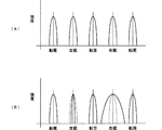
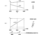
図6は、前記バンドパスフィルタによる周波数フィルタリングで得られる、各方位でのビーム品質(特にビーム幅)を示すものである。 FIG. 6 shows the beam quality (particularly the beam width) in each direction obtained by frequency filtering using the bandpass filter.
(A)は停船時であり、どのような方位についても受信信号ビームの品質は等しい。(B)は船首方向への走航時であり、周波数方位密度の高い左舷では向上するが周波数方位密度の低い右舷では劣化するという問題が生じる。 (A) is when the ship is stopped, and the quality of the received signal beam is the same for any direction. (B) is a time of running in the bow direction, and there is a problem that it is improved on a port with a high frequency orientation density, but deteriorates on a starboard with a low frequency orientation density.
〔第2の課題〕
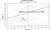
船舶の走航に伴って生じるドップラシフトによって素子方位角に対する受信信号の周波数変化が非線形になることは上述した通りであるが、ドップラシフトが大きくなると、異なった2つの方位角で受信信号が同一周波数になる現象が生じる。図7はその様子を示している。この例では、素子方位角変化に対する受信信号周波数変化が極大点を有する上に凸の曲線となるため、異なった方位から同一周波数の受信信号が到来することになる。この例では、方位角範囲で約−80〜150°、周波数範囲で約80.0〜80.6kHzで、異なった方位から同一周波数の受信信号が到来する可能性がある。
[Second issue]
As described above, the Doppler shift that occurs as the ship travels makes the frequency change of the received signal non-linear with respect to the element azimuth, but as the Doppler shift increases, the received signal is the same at two different azimuths A phenomenon that becomes frequency occurs. FIG. 7 shows this state. In this example, since the received signal frequency change with respect to the element azimuth change has a maximum point, the received signal has the same frequency from different directions. In this example, there is a possibility that received signals of the same frequency may arrive from different directions at an azimuth angle range of about −80 to 150 ° and a frequency range of about 80.0 to 80.6 kHz.
そのため受信信号をバンドパスフィルタで周波数フィルタリングするだけでは方位方向の弁別能が高まらず、擬像の問題が生じる。 For this reason, simply performing frequency filtering on the received signal with a band-pass filter does not improve the discrimination capability in the azimuth direction, resulting in a problem of a false image.
〔第3の課題〕
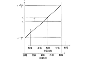
前記超音波送受信装置が船舶に設けられている場合に、船舶が旋回した時には前記ドップラシフトとは別の問題が生じる。すなわち、バースト波を送信してから、その反射波を受信するまでの間にトランスデューサの基準方位がΔθだけ旋回した場合、受信時の旋回後の船首方位はΔθ分だけ変化することになる。その結果、物標の方位をΔθ分だけ誤って検知することになる。
[Third issue]
When the ultrasonic transmission / reception device is provided in a ship, a problem different from the Doppler shift occurs when the ship turns. That is, when the reference orientation of the transducer turns by Δθ between the time when the burst wave is transmitted and the time when the reflected wave is received, the bow direction after the turn at the time of reception changes by Δθ. As a result, the direction of the target is erroneously detected by Δθ.
また、受信中の旋回により、送信時の周波数方位と受信周波数方位とが一致しなくなり、前記バンドパスフィルタによるフィルタリングで結果的に他の方位の受信信号を選択してしまうことになる。これにより、各方位の受信信号を二次元の画像として表示した際に、実際の物標が存在する方位方向の位置がずれたり、感度が低下したりするという問題が生じる。 Further, due to the turning during reception, the frequency azimuth at the time of transmission does not coincide with the reception frequency azimuth, and as a result, a received signal of another azimuth is selected by the filtering by the bandpass filter. As a result, there is a problem that when the received signals of each azimuth are displayed as a two-dimensional image, the position in the azimuth direction where the actual target is present is shifted or the sensitivity is lowered.
図8はその様子を示している。船舶が面舵で(右方向に)旋回している時、素子方位角で船首方向から到来する受信信号周波数はfrとなって、船首方位へ送信した送信信号の周波数fcより高くなる。しかし、船首方向から到来する信号であるので、中心周波数fcのバンドパスフィルタでフィルタリングすることになり、受信感度が低下する。 FIG. 8 shows this state. When the ship is turning by the rudder (rightward), the reception signal frequency arriving from the bow direction at the element azimuth becomes fr, which is higher than the frequency fc of the transmission signal transmitted to the bow direction. However, since it is a signal coming from the bow direction, it is filtered by a bandpass filter having a center frequency fc, and the reception sensitivity is lowered.
そこで、この発明の目的は、上述の各種課題を解消して、方位方向の弁別能を高め、擬像の発生を抑制し、方位方向の探知精度の低下および感度低下を防止した超音波送受信装置およびスキャニングソナーを提供することにある。 SUMMARY OF THE INVENTION Accordingly, an object of the present invention is to solve the above-mentioned various problems, improve the discrimination capability in the azimuth direction, suppress the generation of pseudo-images, and prevent the deterioration in detection accuracy and sensitivity in the azimuth direction. And to provide scanning sonar.
(1)この発明の超音波送受信装置は、方位方向に複数の振動子を配列したトランスデューサと、該トランスデューサの複数の振動子を駆動して超音波を送信する送信制御手段と、前記超音波の物標からの反射波を受けて生じる前記複数の振動子の受信信号を基に、所定方位から到来する受信信号を合成して(すなわち受信ビームを形成して)合成受信信号を得る受信制御手段とを備え、送信制御手段は、トランスデューサの基準方位を基準とする方位に応じて送信周波数の差が異なる(例えばリニアに異なる)第1・第2の2つのバースト波が送信されるように前記複数の振動子を駆動し、受信制御手段は、前記第1のバースト波による前記合成受信信号の複素共役と前記第2のバースト波による前記合成受信信号との積を入力波形として求める手段と、前記第1のバースト波の複素共役と前記第2のバースト波との積に相当する波形と前記入力波形との相互相関処理を行う相関処理手段と、を備えたことを特徴としている。 (1) An ultrasonic transmission / reception apparatus according to the present invention includes a transducer having a plurality of transducers arranged in an azimuth direction, transmission control means for driving the plurality of transducers of the transducer to transmit ultrasonic waves, Reception control means for synthesizing reception signals coming from a predetermined direction (that is, forming a reception beam) to obtain a combined reception signal based on reception signals of the plurality of transducers generated by receiving reflected waves from a target And the transmission control means is configured to transmit the first and second burst waves having different transmission frequencies (for example, linearly different) depending on an orientation relative to the reference orientation of the transducer. The plurality of transducers are driven, and the reception control unit uses a product of a complex conjugate of the combined reception signal by the first burst wave and the combined reception signal by the second burst wave as an input waveform. And correlation processing means for performing a cross-correlation process between the waveform corresponding to the product of the complex conjugate of the first burst wave and the second burst wave and the input waveform. It is said.
(2)超音波の送信から反射波の受信までのトランスデューサの基準方位の旋回角(Δθ)を検知する手段を備え、その旋回角だけ前記相関処理手段の前記方位に応じた送信周波数の差(フィルタの適応周波数)を偏位(シフト)させる手段を備える。 (2) A means for detecting the turning angle (Δθ) of the reference orientation of the transducer from the transmission of the ultrasonic wave to the reception of the reflected wave is provided, and the difference in transmission frequency corresponding to the orientation of the correlation processing means (only the turning angle) Means for shifting (adapting the adaptive frequency of the filter).
(3)前記送信制御手段は、前記第1・第2のバースト波を例えば所定の遅延時間をもって時間的に重ならないタイミングで順次送信する。 (3) The transmission control means sequentially transmits the first and second burst waves at a timing that does not overlap in time with a predetermined delay time, for example.
(4)この発明のスキャニングソナーは、前記超音波送受信装置と、その送信制御手段および受信制御手段の制御により、探査すべき方位を順次走査して、各方位の前記相関処理手段によってフィルタリングされた信号から探知範囲の探知画像データを求め、該探知画像データを表示する手段とを備えたことを特徴としている。
(4) The scanning sonar according to the present invention sequentially scans the azimuth to be searched under the control of the ultrasonic transmission / reception apparatus and its transmission control means and reception control means, and is filtered by the correlation processing means of each azimuth. Means for obtaining detection image data in a detection range from the signal and displaying the detection image data.
(1)前記送信制御手段により、トランスデューサの基準方位を基準とする方位(素子方位角)に応じて、送信周波数の差が異なる第1・第2の2つのバースト波が送信され、前記相関フィルタにより、第1のバースト波による合成受信信号の複素共役と第2のバースト波による合成受信信号との積である入力波形と、第1のバースト波の複素共役と第2のバースト波との積に相当する波形との相互相関処理を行うが、各方位において第1・第2のバースト波に生じるドップラシフトはほぼ等しいので、第1のバースト波による合成受信信号と第2のバースト波による合成受信信号の複素共役との積を求めることによってドップラ成分がキャンセルされる。そのため、素子方位角に対する第1・第2のバースト波の周波数差変化がリニアである特性が利用できて、ちょうど従来のDFM法で停船時に得られる特性と同等の特性が走航時にも得られることになる。 (1) The transmission control means transmits first and second burst waves having different transmission frequency differences according to an orientation (element orientation angle) based on a reference orientation of the transducer, and the correlation filter The product of the input waveform, which is the product of the complex conjugate of the combined received signal by the first burst wave, and the combined received signal of the second burst wave, and the product of the complex conjugate of the first burst wave and the second burst wave Although the cross-correlation processing with the waveform corresponding to is performed, since the Doppler shifts generated in the first and second burst waves are almost equal in each direction, the synthesized reception signal by the first burst wave and the synthesis by the second burst wave The Doppler component is canceled by obtaining the product of the received signal and the complex conjugate. Therefore, the characteristic that the frequency difference change of the first and second burst waves with respect to the element azimuth is linear can be used, and the characteristic equivalent to the characteristic obtained when the ship is stopped by the conventional DFM method can be obtained even during the cruise. It will be.
(2)船舶の旋回(回頭)に伴って、超音波の送信から反射波の受信までのトランスデューサの基準方位が旋回するが、その旋回角(Δθ)だけ前記相関フィルタの前記方位に応じた送信周波数の差に対応するフィルタの適応周波数を偏位(シフト)させることによって、旋回時の方位方向の探知精度の低下および感度低下が防止できる。 (2) The reference azimuth of the transducer from the transmission of the ultrasonic wave to the reception of the reflected wave turns with the turning (turning) of the ship, but only the turning angle (Δθ) is transmitted according to the azimuth of the correlation filter. By deviating (shifting) the adaptive frequency of the filter corresponding to the frequency difference, it is possible to prevent a decrease in detection accuracy and a decrease in sensitivity in the azimuth direction during turning.
(3)第1・第2のバースト波を時間的に重ならないタイミングで順次送信することによって、第1・第2のバースト波の混合による混変調歪みが生じることがなく、新たな問題が回避できる。 (3) By sequentially transmitting the first and second burst waves at a timing that does not overlap in time, intermodulation distortion due to mixing of the first and second burst waves does not occur, and a new problem is avoided. it can.
(4)探知物標との間でドップラシフトが生じる状態でも、受信ビーム特性が方位によらずに一様とすることができ、全方位方向について方位方向の弁別能が等しい探知画像が得られる。 (4) Even in the state where Doppler shift occurs between detection targets, the reception beam characteristics can be made uniform regardless of the direction, and a detection image having the same discrimination ability in the direction can be obtained in all directions. .
この発明の実施形態に係る超音波送受信装置およびスキャニングソナーについて各図を参照して説明する。
図9はこの発明に係る超音波送受信装置が送受信する第1・第2の2つのバースト波の素子方位角と周波数との関係を示す図である。ここで、f1(θ)で示す直線はドップラシフトを受けていない時の第1のバースト波の周波数、f2(θ)で示す直線はドップラシフトを受けていない時の第2のバースト波の周波数である。また、fdpr1(θ)は、船舶が船首方向に走航することによって生じるドップラシフトを受けている状態での第1のバースト波の受信信号の周波数である。同様にfdpr2(θ)は、ドップラシフトを受けている状態での第2のバースト波の受信信号の周波数である。また、Δf(θ)は上記f1(θ)とf2(θ)の差の周波数である。
An ultrasonic transmission / reception apparatus and scanning sonar according to an embodiment of the present invention will be described with reference to the drawings.
FIG. 9 is a diagram showing the relationship between the element azimuth angle and the frequency of the first and second burst waves transmitted and received by the ultrasonic transmission / reception apparatus according to the present invention. Here, the straight line indicated by f1 (θ) is the frequency of the first burst wave when not subjected to Doppler shift, and the straight line indicated by f2 (θ) is the frequency of the second burst wave when not subjected to Doppler shift. It is. Further, fdpr1 (θ) is the frequency of the received signal of the first burst wave in a state where the ship is subjected to Doppler shift generated by traveling in the bow direction. Similarly, fdpr2 (θ) is the frequency of the received signal of the second burst wave in a state where it is subjected to Doppler shift. Δf (θ) is the frequency of the difference between f1 (θ) and f2 (θ).
ここで音速をC、船速をvとすると次の関係が成り立つ。 Here, when the sound speed is C and the ship speed is v, the following relationship is established.

音速C(=1500m/s)に比べて船速vははるかに小さく、2v/(C−v)は1に比べて非常に小さな値となって無視できる。 The ship speed v is much smaller than the speed of sound C (= 1500 m / s), and 2v / (Cv) is much smaller than 1 and can be ignored.
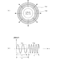
図10は第1・第2のバースト波について示す図である。(A)はトランスデューサから全周囲(360°)方向にTだけ持続する第1のバースト波TX1と、それに続く第2のバースト波TX2が送信された直後の様子を示している。また(B)はその波形図である。第2のバースト波TX2は第1のバースト波TX1の開始時からTdだけ遅れて送信される。ここでT<Tdであるので、第1・第2のバースト波TX1,TX2は時間的に重ならないタイミングで順次送信される。 FIG. 10 is a diagram showing the first and second burst waves. (A) shows a state immediately after the first burst wave TX1 that lasts by T in the entire circumference (360 °) direction and the subsequent second burst wave TX2 are transmitted from the transducer. (B) is a waveform diagram thereof. The second burst wave TX2 is transmitted with a delay of Td from the start of the first burst wave TX1. Here, since T <Td, the first and second burst waves TX1, TX2 are sequentially transmitted at a timing that does not overlap in time.
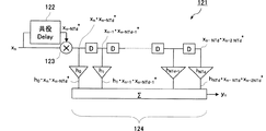
図11は前記第1・第2のバースト波の物標からの反射波を受けることによって生じる受信信号と、その処理について示す図である。(A)は、トランスデューサ101の基準方位から右回りにθLの方向すなわち素子方位角θL方向から反射波が到来しつつある様子と、受信ビームの指向特性とを示している。
FIG. 11 is a diagram showing a received signal generated by receiving a reflected wave from the target of the first and second burst waves and its processing. (A) shows a state in which the reflected waves from the direction, namely a head azimuth angle theta L direction theta L clockwise is being reached, the directional characteristics of the received beam from the reference orientation of the
図11の(B)は上記バースト波の送信信号xTX、受信信号xRX、および相関フィルタの構成について示している。相関フィルタ121は、第1のバースト波によって生じる合成受信信号(受信ビーム形成後の合成受信信号)を前記Tdだけ遅延させる遅延回路122、この遅延回路122の出力の複素共役信号を第2のバースト波による合成受信信号に掛け合わせて入力波形を生成する掛け算回路123、およびバンドパスフィルタ124とで構成している。この相関フィルタ121は、第1のバースト波の複素共役と第2のバースト波との積に相当する波形hと上記入力波形との相互相関処理を行い、入力波形とマッチする信号強度の信号を出力する。
上記遅延回路122および掛け算回路123がこの発明に係る相関処理手段に相当する。
FIG. 11B shows the configuration of the burst wave transmission signal x TX , reception signal x RX , and correlation filter. The
The
上記送信信号は次式で表される。 The transmission signal is expressed by the following equation.
但し、φ1は第1のバースト波の角周波数、φ2は第2のバースト波の角周波数、θは素子方位角である。 Where φ1 is the angular frequency of the first burst wave, φ2 is the angular frequency of the second burst wave, and θ is the element azimuth angle.
また、送信信号xTXに対する、距離L・方位θLでの受信信号xRXは次式で表される。 Further, the reception signal x RX at the distance L and the direction θ L with respect to the transmission signal x TX is expressed by the following equation.
但し、B1は第1のバースト波の周波数での物標の反射係数、B2は第2のバースト波の周波数での物標の反射係数である。 However, B1 is the reflection coefficient of the target at the frequency of the first burst wave, and B2 is the reflection coefficient of the target at the frequency of the second burst wave.
バンドパスフィルタ124は、入力波形とマッチするように、そのフィルタインパルスを次のように定める。
The
但し、wは重み係数、φは位相である。
図12の(A)は第1・第2のバースト波の反射信号である。
However, w is a weighting factor and φ is a phase.
FIG. 12A shows reflected signals of the first and second burst waves.
この時、方位θhに相当するフィルタ出力yは次式のようになる。(簡単化のためにトランスデューサへの入力から受信ビーム形成出力までのゲインを1としている。) At this time, the filter output y corresponding to the azimuth θh is as follows. (For simplicity, the gain from the input to the transducer to the received beam forming output is set to 1.)
但し、
図12の(B)は、計算を簡単にするために、TL+Td≡0として時間軸を推移した状態を示している。ここで、yは次式で表される。
However,
FIG. 12B shows a state in which the time axis is changed as T L + Td≡0 in order to simplify the calculation. Here, y is expressed by the following equation.
ここで、第1のバースト波の位相項φ1,第2のバースト波の位相項φ2を次式のように置く。 Here, the phase term φ1 of the first burst wave and the phase term φ2 of the second burst wave are set as follows.
但し、
ωd:ドップラシフト周波数
ωc1:第1バースト波の基準方位への送信周波数
ωc2:第2バースト波の基準方位への送信周波数
BDFM1:第1のバースト波のDFM掃引幅
BDFM2:第2のバースト波のDFM掃引幅
である。また、ここではDFM−FM送信法にも適用できるように表していて、
BFM1:第1のバースト波のFM掃引幅
BFM2:第2のバースト波のFM掃引幅
である。
However,
ωd: Doppler shift frequency ωc1: Transmission frequency of the first burst wave in the reference direction ωc2: Transmission frequency of the second burst wave in the reference direction B DFM1 : DFM sweep width of the first burst wave B DFM2 : Second burst This is the DFM sweep width of the wave. In addition, here, it is expressed so as to be applicable to the DFM-FM transmission method,
B FM1 : FM sweep width of the first burst wave B FM2 : FM sweep width of the second burst wave
ここで、φ1−φ2によりx1、x2のドップラ成分ωdがキャンセルされる。後は、Δωc、ΔBDFM、ΔBFMに応じたフィルタリング処理を行う。このフィルタリング処理は従来のDFM処理と同じである。 Here, the Doppler components ωd of x1 and x2 are canceled by φ1-φ2. After that, filtering processing according to Δωc, ΔB DFM , ΔB FM is performed. This filtering process is the same as the conventional DFM process.
そこで、フィルタインパルスの位相項φhを次式のように定めて入力信号に対してマッチングさせる。 Therefore, the phase term φh of the filter impulse is determined as follows and matched with the input signal.
DFM−CW送信法の場合は、上式でΔBFM=0である。 In the case of the DFM-CW transmission method, ΔB FM = 0 in the above equation.
このようにして、前記相関フィルタ121のバンドパスフィルタ124は、第1・第2のバースト波の周波数差で決まる位相分だけ移相しつつ第1・第2のバースト波の持続時間分について積分する。
In this way, the band-
前記相関フィルタを備えた超音波送受信装置全体の構成をブロック図として図13に示す。ここで、発振回路120はトランスデューサ101の各振動子を駆動する駆動信号を生成し、増幅回路103がそれを増幅し、トラップ102を介してトランスデューサ101の各振動子を駆動する。この発振回路120および増幅回路103はこの発明に係る送信制御手段に相当する。プリアンプ105は受信ビームを形成すべき方向に向く所定の広がりをもつ開口内の複数の振動子の受信信号を増幅し、プリフィルタ106は不要な雑音周波数成分を除去する。A/Dコンバータ107は各信号をディジタルデータへ変換し、ビームフォーマ108は受信すべき方位θhを向く鋭い受信ビームを形成する。
FIG. 13 is a block diagram showing the configuration of the entire ultrasonic transmission / reception apparatus including the correlation filter. Here, the
相関フィルタ121は、ビームフォーマ108で合成された合成受信信号に対して探知すべき方位の素子方位角θhに応じて、図11(B)に示したバンドパスフィルタ124の通過帯域の中心周波数を定める。
図14は前記相関フィルタの具体的な構成例を示す図である。図14において、遅延回路D、係数乗算回路h、および加算回路Σでバンドパスフィルタ124を構成している。
FIG. 14 is a diagram illustrating a specific configuration example of the correlation filter. In FIG. 14, a delay circuit D, a coefficient multiplication circuit h, and an addition circuit Σ constitute a
共役遅延回路122は、入力信号Xnを、第1のバースト波と第2のバースト波の送信開始タイミングの時間差に相当するステップ数NTd分だけ遅延させるとともに入力信号の共役信号を出力する。掛け算回路123は、入力信号Xnと共役遅延回路122の出力信号とを掛け算する。このバンドパスフィルタ124の演算を式で表すと次の通りである。
The
![]()
![]()
ここでTはバースト波の持続時間、Tdは第1のバースト波の送信開始タイミングと第2のバースト波の送信開始タイミングとの時間差、φ(τ)は第1・第2のバースト波の差の周波数での位相角である。 Where T is the duration of the burst wave, Td is the time difference between the transmission start timing of the first burst wave and the transmission start timing of the second burst wave, and φ (τ) is the difference between the first and second burst waves. Is the phase angle at the frequency of.
図13に示したバンドパスフィルタ124内の係数乗算回路hの係数は、第1・第2のバースト波の送信信号の方位毎の周波数差Δf(φ)で決まる係数とする。すなわち
φ(t)=2πΔf(φ)t
で表した時、
h0=e−jφ0
h1=e−jφ1
・
・
・
hNTd-1=e−jφNTd−1
hNTd = e−jφNTd
の関係で表すことができる。
The coefficient of the coefficient multiplication circuit h in the
When expressed in
h0 = e− jφ0
h1 = e− jφ1
・
・
・
h NTd-1 = e- jφNTd-1
h NTd = e −jφNTd
It can be expressed by the relationship.
図15は前記相関フィルタの別の構成例を示す図である。遅延回路D、係数乗算回路h、および加算回路Σでバンドパスフィルタ124を構成している。この例では入力信号Xnと共役遅延回路122の出力信号とを別々に遅延させて、それぞれの段で掛け算を行っている。
FIG. 15 is a diagram showing another configuration example of the correlation filter. The delay circuit D, the coefficient multiplication circuit h, and the addition circuit Σ constitute a
次に、第2の実施形態に係る超音波送受信装置について図16を基に説明する。
図16においてf1(θ)は第1のバースト波の方位ごとの送信信号の周波数、f2(θ)は第2のバースト波の方位ごとの送信信号の周波数、またΔf(θ)は上記f1(θ)とf2(θ)の差の周波数である。同図に示すように、送信から反射波の受信までの間にトランスデューサの基準方位がΔθだけ旋回した場合、受信時の旋回後の船首方位はΔθ分だけ変化することになる。そこで、この実施形態では第1・第2のバースト波の送信から受信までの船首方位の旋回角Δθを検知し、前記相関フィルタの方位に応じた送信周波数の差(バンドパスフィルタの中心周波数)を偏位させる。
Next, an ultrasonic transmission / reception apparatus according to the second embodiment will be described with reference to FIG.
In FIG. 16, f1 (θ) is the frequency of the transmission signal for each direction of the first burst wave, f2 (θ) is the frequency of the transmission signal for each direction of the second burst wave, and Δf (θ) is f1 ( The frequency of the difference between θ) and f2 (θ). As shown in the figure, when the reference orientation of the transducer turns by Δθ between transmission and reception of the reflected wave, the heading after turning at the time of reception changes by Δθ. Therefore, in this embodiment, the turning angle Δθ of the heading from transmission to reception of the first and second burst waves is detected, and the difference in transmission frequency according to the direction of the correlation filter (center frequency of the bandpass filter) To deviate.
そのため、ジャイロコンパスやGPSコンパス等によって船首方位のデータを入力し、送信時と受信時の船首方位データの差Δθを算出し、その分、上記相関フィルタ内のバンドパスフィルタの中心周波数を偏位させる。 Therefore, the heading data is input using a gyrocompass or GPS compass, and the difference Δθ between the heading data at the time of transmission and at the time of reception is calculated, and the center frequency of the bandpass filter in the correlation filter is shifted accordingly. Let
なお、第1・第2の実施形態では、送信制御手段が、トランスデューサの基準方位を基準とする方位に応じて送信周波数の差がリニアに異なる第1・第2の2つのバースト波が送信されるように複数の振動子を駆動したが、本願発明は第1・第2の2つのバースト波の送信周波数の差が方位変化に応じてリニアに変化するものに限らない。第1・第2の2つのバースト波の送信周波数の差が、隣接する方位ごとに異なっていればよい。また、第1・第2のバースト波をそれぞれ所定周波数幅でFM掃引し、各方位について第1・第2のバースト波の中心周波数の差が隣接する方位ごとに異なるようにしてもよい。 In the first and second embodiments, the transmission control means transmits the first and second burst waves having linearly different transmission frequencies in accordance with the orientation based on the reference orientation of the transducer. However, the present invention is not limited to the one in which the difference between the transmission frequencies of the first and second burst waves changes linearly in accordance with the azimuth change. It is only necessary that the difference between the transmission frequencies of the first and second burst waves is different for each adjacent direction. Further, the first and second burst waves may be swept with a predetermined frequency width, and the difference between the center frequencies of the first and second burst waves may be different for each adjacent direction.
次に、第3の実施形態に係るスキャニングソナーについて図17・図18を参照して説明する。
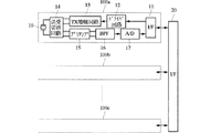
図17は、スキャニングソナーの送受信チャンネルの構成を示すブロック図である。図17において、ドライバ回路12は、インタフェース20,11を介して、後述するプログラマブル送信ビーム形成制御部から与えられた2値化された駆動コードを、ハーフブリッジ型PDM送信アンプ(パルス幅変調(PDM:pulse-duration modulation )により送信するための送信アンプ)のFETを駆動するための、2種類のドライブ信号にデコードする。
Next, a scanning sonar according to the third embodiment will be described with reference to FIGS.
FIG. 17 is a block diagram showing the configuration of the transmission / reception channel of the scanning sonar. In FIG. 17, the
TX増幅回路13は、上記ハーフブリッジ型PDM送信回路によりPDM変調された2値信号を出力する。これにより、送受切替回路14を介して振動子10を駆動する。送受切替回路14は、送信期間にTX増幅回路13の出力信号を振動子10へ導き、受信期間に、振動子10が出力した信号をプリアンプ15へ受信信号として導く。プリアンプ15は、この受信信号を増幅し、バンドパスフィルタ16は、受信信号の周波数帯域以外のノイズ成分を除去する。A/Dコンバータ17は、その受信周波数帯域の信号を所定のサンプリング周期でサンプリングし、ディジタルデータ列に変換する。
The
上述の部分で送受信チャンネル100を構成する。この送受信チャンネルは、100a,100b,・・・100nで示すように、振動子10の数だけ備えている。
The transmission / reception channel 100 is composed of the above-described portions. As shown by 100a, 100b,... 100n, this transmission / reception channel is provided by the number of
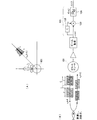
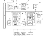
図18は、図17に示した複数の送受信チャンネル100を用いて送信ビームおよび受信ビームを形成するとともに、所定探知範囲の探知画像を生成するためのブロック図である。図18におけるインタフェース20は、図17に示したインタフェース20のことである。
FIG. 18 is a block diagram for forming a transmission beam and a reception beam using the plurality of transmission / reception channels 100 shown in FIG. 17 and generating a detection image in a predetermined detection range. The
図18において、26はプログラマブル送信ビーム形成制御部である。このプログラマブル送信ビーム形成制御部26は、送信信号生成回路21、波形メモリ24およびTX−DSP25を含んでいる。送信信号生成回路21には、タイミングジェネレータ22と係数テーブル23とを設けている。タイミングジェネレータ22は、送信信号の生成タイミングの基準となる信号を発生する。TX−DSP25は送信信号生成用DSP(ディジタル信号処理回路)である。
In FIG. 18, 26 is a programmable transmission beam forming control unit. The programmable transmission
TX−DSP25は、PDM変調波形を生成するための、2値化された基準駆動コードを、32方位に対してそれぞれ8種類の異なるウェイトについて計算し、波形メモリ24へ書き込む。さらに、送信ビーム形成のために、各チャンネルの遅延量、ウェイト値、送信方位番号(基準方位からの素子方位角)を送信周期毎に計算し、これらをテーブルとして係数テーブル23に書き込む。
The TX-
送信信号生成回路21は、係数テーブル23から係数を読み出し、該当する駆動コードを波形メモリから読み出して、各チャンネル毎に送信方位番号に対応する基準駆動コードとウェイト値と遅延量とに基づいて駆動コードを生成する。
The transmission
バッファメモリ27は、インタフェース20を介して各チャンネルからの受信データを一時記憶するメモリである。28はプログラマブル受信ビーム形成制御部であり、RX−DSP29、係数テーブル30、および受信ビーム形成演算部31を含んでいる。RX−DSP29は、各受信ビーム毎に各振動子による受信信号の位相とウェイトを計算し、係数テーブル30へ書き込む。受信ビーム形成演算部31は、各振動子の受信信号に対して係数テーブル30に書き込まれた位相とウェイトの計算を行って合成することにより合成受信信号を得る。この合成受信信号を受信ビーム毎の時系列データとして求め、これをバッファメモリ32へ書き込む。
The
33はプログラマブルフィルタであり、フィルタDSP34、係数テーブル35、およびフィルタ演算部36から構成している。このプログラマブルフィルタ33は、各受信ビームの受信信号毎に前述した相関フィルタ処理を行う。フィルタDSP34は、ビーム毎に所定の通過帯域フィルタ特性を得るためのフィルタ係数を計算し、それを係数テーブル35へ書き込む。フィルタ演算部36は係数テーブル35の係数を基に前記ディジタルフィルタの演算を行い、帯域処理済受信信号を求める。
エンベロープ検出部40は、各受信ビームの帯域処理済受信信号のエンベロープ(包絡線)を検出する。
The
イメージ処理部41は、各受信ビームの各距離における受信信号強度をイメージ情報化してディスプレイ42へ出力する。これによりディスプレイ42に所定探知範囲の探知画像を表示する。
The
操作部39は、探知範囲のティルト角の指示等を行う入力部である。ホストCPU37は、インタフェース38を介して操作部39の指示内容を読み取り、上述した各部の制御を行う。
The
なお、図18では省略したが、船舶のローリングやピッチングを検出する装置からそれらの情報を入力し、TX−DSP25は、船舶の動揺に関わらず常に所定の探知範囲に送信ビームを形成するように、係数テーブル23に書き込むべき係数を計算する。同様に、船舶のローリングやピッチングに応じて、RX−DSP29は、船舶の動揺に関わらず常に所定方位に受信ビームを形成するように、係数テーブル30に書き込むべき係数を計算する。
Although omitted in FIG. 18, such information is input from a device that detects rolling and pitching of the ship, and the TX-
103−増幅回路
104−発振回路
105−プリアンプ
106−プリフィルタ
107−A/Dコンバータ
108−ビームフォーマ
109−バンドパスフィルタ
110−信号検出回路
120−送信信号発生回路
121−相関フィルタ
122−共役遅延回路
123−掛け算回路
124−バンドパスフィルタ
103-amplifier circuit 104-oscillator circuit 105-preamplifier 106-prefilter 107-A / D converter 108-beamformer 109-bandpass filter 110-signal detection circuit 120-transmission signal generation circuit 121-correlation filter 122-conjugate delay circuit 123-Multiplication circuit 124-Band pass filter
Claims (4)
前記送信制御手段は、前記トランスデューサの基準方位を基準とする方位に応じて送信周波数の差が異なる第1・第2の2つのバースト波が送信されるように前記複数の振動子を駆動するものとし、
前記受信制御手段は、前記第1のバースト波による前記合成受信信号の複素共役と前記第2のバースト波による前記合成受信信号との積を入力波形として求める手段と、前記第1のバースト波の複素共役と前記第2のバースト波との積に相当する波形と前記入力波形との相互相関処理を行う相関処理手段と、を備えたことを特徴とする超音波送受信装置。 A transducer in which a plurality of transducers are arranged in the azimuth direction, a transmission control means for driving the plurality of transducers of the transducers to transmit ultrasonic waves, and the plural waves generated by receiving reflected waves from the ultrasonic target In an ultrasonic transmission / reception apparatus comprising a reception control means for synthesizing a reception signal arriving from a predetermined direction and obtaining a combined reception signal based on the reception signal of
The transmission control means drives the plurality of vibrators such that two first and second burst waves having different transmission frequencies are transmitted according to an orientation based on a reference orientation of the transducer. age,
The reception control means includes a means for obtaining a product of a complex conjugate of the combined received signal by the first burst wave and the combined received signal by the second burst wave as an input waveform; An ultrasonic transmission / reception apparatus comprising: correlation processing means for performing cross-correlation processing between a waveform corresponding to a product of a complex conjugate and the second burst wave and the input waveform.
Priority Applications (1)
| Application Number | Priority Date | Filing Date | Title |
|---|---|---|---|
| JP2006325504A JP5259076B2 (en) | 2006-12-01 | 2006-12-01 | Ultrasonic transceiver and scanning sonar |
Applications Claiming Priority (1)
| Application Number | Priority Date | Filing Date | Title |
|---|---|---|---|
| JP2006325504A JP5259076B2 (en) | 2006-12-01 | 2006-12-01 | Ultrasonic transceiver and scanning sonar |
Publications (2)
| Publication Number | Publication Date |
|---|---|
| JP2008139144A JP2008139144A (en) | 2008-06-19 |
| JP5259076B2 true JP5259076B2 (en) | 2013-08-07 |
Family
ID=39600775
Family Applications (1)
| Application Number | Title | Priority Date | Filing Date |
|---|---|---|---|
| JP2006325504A Expired - Fee Related JP5259076B2 (en) | 2006-12-01 | 2006-12-01 | Ultrasonic transceiver and scanning sonar |
Country Status (1)
| Country | Link |
|---|---|
| JP (1) | JP5259076B2 (en) |
Families Citing this family (2)
| Publication number | Priority date | Publication date | Assignee | Title |
|---|---|---|---|---|
| JP5219526B2 (en) * | 2008-01-19 | 2013-06-26 | 古野電気株式会社 | Underwater detector |
| JP6247397B2 (en) * | 2015-05-07 | 2017-12-13 | エスゼット ディージェイアイ テクノロジー カンパニー リミテッドSz Dji Technology Co.,Ltd | System and method for detecting an object |
Family Cites Families (5)
| Publication number | Priority date | Publication date | Assignee | Title |
|---|---|---|---|---|
| JPH01180483A (en) * | 1988-01-12 | 1989-07-18 | Nec Corp | Sonar equipment |
| JP4057812B2 (en) * | 2001-12-28 | 2008-03-05 | 古野電気株式会社 | Ultrasonic transceiver and scanning sonar |
| JP4164290B2 (en) * | 2002-05-20 | 2008-10-15 | 古野電気株式会社 | Ultrasonic transceiver and scanning sonar |
| JP4184219B2 (en) * | 2003-09-30 | 2008-11-19 | 古野電気株式会社 | Ultrasonic transceiver and scanning sonar |
| JP4953566B2 (en) * | 2004-08-25 | 2012-06-13 | 古野電気株式会社 | Underwater detection device and underwater detection method |
-
2006
- 2006-12-01 JP JP2006325504A patent/JP5259076B2/en not_active Expired - Fee Related
Also Published As
| Publication number | Publication date |
|---|---|
| JP2008139144A (en) | 2008-06-19 |
Similar Documents
| Publication | Publication Date | Title |
|---|---|---|
| US10718858B2 (en) | Echo measuring apparatus, echo sounding apparatus, multibeam echo measuring apparatus, multibeam echo sounding apparatus and aperture synthetic sonar | |
| JP5301882B2 (en) | Pulse signal transmitter / receiver | |
| JP2000157548A (en) | Method and system for imaging ultrasonic wave scattered body | |
| JP4057812B2 (en) | Ultrasonic transceiver and scanning sonar | |
| JP4354736B2 (en) | Ultrasonic transceiver | |
| JP2017227515A (en) | Active sonar and control method for the same | |
| JP6339446B2 (en) | Detection device, detection method, and program | |
| EP2317335B1 (en) | Improved beamforming method for analysing signals received by a transducer arrray, and relative detection system | |
| JP2006208110A (en) | Underwater detector and its display control method | |
| JP6179973B2 (en) | Signal processing device, underwater detection device, signal processing method, and program | |
| JP5259076B2 (en) | Ultrasonic transceiver and scanning sonar | |
| US7164621B2 (en) | Underwater sounding apparatus | |
| JP4184219B2 (en) | Ultrasonic transceiver and scanning sonar | |
| JP2014020907A (en) | Underwater detection device, underwater detection method and program | |
| JP4953566B2 (en) | Underwater detection device and underwater detection method | |
| WO2011058527A1 (en) | Method and apparatus for processing sonar signals | |
| JP3528580B2 (en) | Object measuring device | |
| JPH09243733A (en) | Active sonar | |
| JP6610224B2 (en) | Bistatic active sonar device and its receiver | |
| JP2001074836A (en) | Display device for bistatic active sonar | |
| JP5603355B2 (en) | Ultrasonic measuring device | |
| JP6757083B2 (en) | Echo sounder and multi-beam echo sounder | |
| JP5098131B2 (en) | Multi-beam sonar and signal processing method thereof | |
| JP5219526B2 (en) | Underwater detector | |
| GB2456426A (en) | Underwater Detector |
Legal Events
| Date | Code | Title | Description |
|---|---|---|---|
| A621 | Written request for application examination |
Free format text: JAPANESE INTERMEDIATE CODE: A621 Effective date: 20091124 |
|
| A131 | Notification of reasons for refusal |
Free format text: JAPANESE INTERMEDIATE CODE: A131 Effective date: 20120228 |
|
| A521 | Written amendment |
Free format text: JAPANESE INTERMEDIATE CODE: A523 Effective date: 20120427 |
|
| RD02 | Notification of acceptance of power of attorney |
Free format text: JAPANESE INTERMEDIATE CODE: A7422 Effective date: 20120427 |
|
| TRDD | Decision of grant or rejection written | ||
| A01 | Written decision to grant a patent or to grant a registration (utility model) |
Free format text: JAPANESE INTERMEDIATE CODE: A01 Effective date: 20130423 |
|
| A61 | First payment of annual fees (during grant procedure) |
Free format text: JAPANESE INTERMEDIATE CODE: A61 Effective date: 20130424 |
|
| FPAY | Renewal fee payment (event date is renewal date of database) |
Free format text: PAYMENT UNTIL: 20160502 Year of fee payment: 3 |
|
| R150 | Certificate of patent or registration of utility model |
Free format text: JAPANESE INTERMEDIATE CODE: R150 |
|
| R250 | Receipt of annual fees |
Free format text: JAPANESE INTERMEDIATE CODE: R250 |
|
| LAPS | Cancellation because of no payment of annual fees |