JP5256191B2 - Apparatus and system for in situ measurement of physical parameters - Google Patents
Apparatus and system for in situ measurement of physical parameters Download PDFInfo
- Publication number
- JP5256191B2 JP5256191B2 JP2009508541A JP2009508541A JP5256191B2 JP 5256191 B2 JP5256191 B2 JP 5256191B2 JP 2009508541 A JP2009508541 A JP 2009508541A JP 2009508541 A JP2009508541 A JP 2009508541A JP 5256191 B2 JP5256191 B2 JP 5256191B2
- Authority
- JP
- Japan
- Prior art keywords
- data
- temperature
- user
- processing device
- measurement
- Prior art date
- Legal status (The legal status is an assumption and is not a legal conclusion. Google has not performed a legal analysis and makes no representation as to the accuracy of the status listed.)
- Expired - Fee Related
Links
- 238000012625 in-situ measurement Methods 0.000 title description 2
- 238000005259 measurement Methods 0.000 claims description 72
- 230000036760 body temperature Effects 0.000 claims description 68
- 238000012545 processing Methods 0.000 claims description 53
- 230000033001 locomotion Effects 0.000 claims description 44
- 230000016087 ovulation Effects 0.000 claims description 40
- 238000013500 data storage Methods 0.000 claims description 27
- 238000009529 body temperature measurement Methods 0.000 claims description 26
- 230000005540 biological transmission Effects 0.000 claims description 21
- 241001465754 Metazoa Species 0.000 claims description 14
- 230000008859 change Effects 0.000 claims description 13
- 239000000853 adhesive Substances 0.000 claims description 10
- 230000001070 adhesive effect Effects 0.000 claims description 10
- 238000004891 communication Methods 0.000 claims description 6
- 239000012530 fluid Substances 0.000 claims description 4
- 230000001681 protective effect Effects 0.000 claims description 4
- 229940088597 hormone Drugs 0.000 claims description 3
- 239000005556 hormone Substances 0.000 claims description 3
- 238000002513 implantation Methods 0.000 claims description 3
- 230000002175 menstrual effect Effects 0.000 claims description 3
- 230000003247 decreasing effect Effects 0.000 claims 1
- 238000000034 method Methods 0.000 description 31
- 230000005672 electromagnetic field Effects 0.000 description 14
- 230000008569 process Effects 0.000 description 11
- 238000012546 transfer Methods 0.000 description 10
- 229920001296 polysiloxane Polymers 0.000 description 9
- 230000000694 effects Effects 0.000 description 8
- 238000011065 in-situ storage Methods 0.000 description 8
- 238000012937 correction Methods 0.000 description 7
- 230000006872 improvement Effects 0.000 description 7
- 239000000463 material Substances 0.000 description 7
- 210000003097 mucus Anatomy 0.000 description 7
- 230000004044 response Effects 0.000 description 7
- 210000003756 cervix mucus Anatomy 0.000 description 6
- 230000006870 function Effects 0.000 description 5
- 238000003860 storage Methods 0.000 description 5
- 238000004364 calculation method Methods 0.000 description 4
- 235000013601 eggs Nutrition 0.000 description 4
- 239000010410 layer Substances 0.000 description 4
- 230000007246 mechanism Effects 0.000 description 4
- 230000005906 menstruation Effects 0.000 description 4
- 230000035935 pregnancy Effects 0.000 description 4
- 208000002193 Pain Diseases 0.000 description 3
- 238000013459 approach Methods 0.000 description 3
- 210000004369 blood Anatomy 0.000 description 3
- 239000008280 blood Substances 0.000 description 3
- 230000008878 coupling Effects 0.000 description 3
- 238000010168 coupling process Methods 0.000 description 3
- 238000005859 coupling reaction Methods 0.000 description 3
- 238000001514 detection method Methods 0.000 description 3
- 238000010586 diagram Methods 0.000 description 3
- 230000007613 environmental effect Effects 0.000 description 3
- 238000000605 extraction Methods 0.000 description 3
- 239000007943 implant Substances 0.000 description 3
- 208000005171 Dysmenorrhea Diseases 0.000 description 2
- 238000004458 analytical method Methods 0.000 description 2
- 230000009286 beneficial effect Effects 0.000 description 2
- 230000008901 benefit Effects 0.000 description 2
- 239000003990 capacitor Substances 0.000 description 2
- 239000012212 insulator Substances 0.000 description 2
- 238000012544 monitoring process Methods 0.000 description 2
- 238000001356 surgical procedure Methods 0.000 description 2
- QCVGEOXPDFCNHA-UHFFFAOYSA-N 5,5-dimethyl-2,4-dioxo-1,3-oxazolidine-3-carboxamide Chemical compound CC1(C)OC(=O)N(C(N)=O)C1=O QCVGEOXPDFCNHA-UHFFFAOYSA-N 0.000 description 1
- 206010000084 Abdominal pain lower Diseases 0.000 description 1
- 206010067484 Adverse reaction Diseases 0.000 description 1
- 238000012935 Averaging Methods 0.000 description 1
- 208000031636 Body Temperature Changes Diseases 0.000 description 1
- 102000002322 Egg Proteins Human genes 0.000 description 1
- 108010000912 Egg Proteins Proteins 0.000 description 1
- 206010020751 Hypersensitivity Diseases 0.000 description 1
- 206010021113 Hypothermia Diseases 0.000 description 1
- WHXSMMKQMYFTQS-UHFFFAOYSA-N Lithium Chemical compound [Li] WHXSMMKQMYFTQS-UHFFFAOYSA-N 0.000 description 1
- 206010036772 Proctalgia Diseases 0.000 description 1
- 206010037660 Pyrexia Diseases 0.000 description 1
- XUIMIQQOPSSXEZ-UHFFFAOYSA-N Silicon Chemical compound [Si] XUIMIQQOPSSXEZ-UHFFFAOYSA-N 0.000 description 1
- 210000001015 abdomen Anatomy 0.000 description 1
- 206010000059 abdominal discomfort Diseases 0.000 description 1
- 208000020560 abdominal swelling Diseases 0.000 description 1
- 230000001133 acceleration Effects 0.000 description 1
- 230000003044 adaptive effect Effects 0.000 description 1
- 239000012790 adhesive layer Substances 0.000 description 1
- 230000006838 adverse reaction Effects 0.000 description 1
- 208000030961 allergic reaction Diseases 0.000 description 1
- 230000000740 bleeding effect Effects 0.000 description 1
- 230000036772 blood pressure Effects 0.000 description 1
- 210000001124 body fluid Anatomy 0.000 description 1
- 239000010839 body fluid Substances 0.000 description 1
- 210000000481 breast Anatomy 0.000 description 1
- 230000015556 catabolic process Effects 0.000 description 1
- 230000006835 compression Effects 0.000 description 1
- 238000007906 compression Methods 0.000 description 1
- 239000003433 contraceptive agent Substances 0.000 description 1
- 230000002254 contraceptive effect Effects 0.000 description 1
- 238000007796 conventional method Methods 0.000 description 1
- 230000036757 core body temperature Effects 0.000 description 1
- 230000007797 corrosion Effects 0.000 description 1
- 238000005260 corrosion Methods 0.000 description 1
- 238000006731 degradation reaction Methods 0.000 description 1
- 230000001627 detrimental effect Effects 0.000 description 1
- 238000003745 diagnosis Methods 0.000 description 1
- 238000009826 distribution Methods 0.000 description 1
- 235000014103 egg white Nutrition 0.000 description 1
- 210000000969 egg white Anatomy 0.000 description 1
- 239000000284 extract Substances 0.000 description 1
- 230000035558 fertility Effects 0.000 description 1
- 230000004720 fertilization Effects 0.000 description 1
- 239000006260 foam Substances 0.000 description 1
- 230000005484 gravity Effects 0.000 description 1
- 231100001261 hazardous Toxicity 0.000 description 1
- 230000003054 hormonal effect Effects 0.000 description 1
- 230000002631 hypothermal effect Effects 0.000 description 1
- 210000000987 immune system Anatomy 0.000 description 1
- 208000015181 infectious disease Diseases 0.000 description 1
- 238000002347 injection Methods 0.000 description 1
- 239000007924 injection Substances 0.000 description 1
- 230000001788 irregular Effects 0.000 description 1
- 238000012886 linear function Methods 0.000 description 1
- 239000007788 liquid Substances 0.000 description 1
- 229910052744 lithium Inorganic materials 0.000 description 1
- 230000007774 longterm Effects 0.000 description 1
- 239000000314 lubricant Substances 0.000 description 1
- 238000004519 manufacturing process Methods 0.000 description 1
- 238000010339 medical test Methods 0.000 description 1
- 239000002184 metal Substances 0.000 description 1
- 229910052751 metal Inorganic materials 0.000 description 1
- 239000002923 metal particle Substances 0.000 description 1
- 238000012986 modification Methods 0.000 description 1
- 230000004048 modification Effects 0.000 description 1
- 230000008520 organization Effects 0.000 description 1
- 230000010355 oscillation Effects 0.000 description 1
- 230000027758 ovulation cycle Effects 0.000 description 1
- 230000035699 permeability Effects 0.000 description 1
- 230000000704 physical effect Effects 0.000 description 1
- 230000035479 physiological effects, processes and functions Effects 0.000 description 1
- 229920001084 poly(chloroprene) Polymers 0.000 description 1
- 229920000642 polymer Polymers 0.000 description 1
- 238000003825 pressing Methods 0.000 description 1
- 230000001020 rhythmical effect Effects 0.000 description 1
- 239000011435 rock Substances 0.000 description 1
- 210000003296 saliva Anatomy 0.000 description 1
- 238000005070 sampling Methods 0.000 description 1
- 230000035945 sensitivity Effects 0.000 description 1
- 230000001568 sexual effect Effects 0.000 description 1
- 229910052710 silicon Inorganic materials 0.000 description 1
- 239000010703 silicon Substances 0.000 description 1
- 230000004622 sleep time Effects 0.000 description 1
- 239000000243 solution Substances 0.000 description 1
- 230000003595 spectral effect Effects 0.000 description 1
- 238000013179 statistical model Methods 0.000 description 1
- 238000007920 subcutaneous administration Methods 0.000 description 1
- 239000013589 supplement Substances 0.000 description 1
- 238000012360 testing method Methods 0.000 description 1
- 238000012549 training Methods 0.000 description 1
- 210000002700 urine Anatomy 0.000 description 1
- 230000002618 waking effect Effects 0.000 description 1
- 229910000859 α-Fe Inorganic materials 0.000 description 1
Images


Classifications
-
- A—HUMAN NECESSITIES
- A61—MEDICAL OR VETERINARY SCIENCE; HYGIENE
- A61B—DIAGNOSIS; SURGERY; IDENTIFICATION
- A61B10/00—Other methods or instruments for diagnosis, e.g. instruments for taking a cell sample, for biopsy, for vaccination diagnosis; Sex determination; Ovulation-period determination; Throat striking implements
- A61B10/0012—Ovulation-period determination
-
- A—HUMAN NECESSITIES
- A61—MEDICAL OR VETERINARY SCIENCE; HYGIENE
- A61B—DIAGNOSIS; SURGERY; IDENTIFICATION
- A61B5/00—Measuring for diagnostic purposes; Identification of persons
- A61B5/0002—Remote monitoring of patients using telemetry, e.g. transmission of vital signals via a communication network
- A61B5/0004—Remote monitoring of patients using telemetry, e.g. transmission of vital signals via a communication network characterised by the type of physiological signal transmitted
- A61B5/0008—Temperature signals
-
- A—HUMAN NECESSITIES
- A61—MEDICAL OR VETERINARY SCIENCE; HYGIENE
- A61B—DIAGNOSIS; SURGERY; IDENTIFICATION
- A61B5/00—Measuring for diagnostic purposes; Identification of persons
- A61B5/0002—Remote monitoring of patients using telemetry, e.g. transmission of vital signals via a communication network
- A61B5/0031—Implanted circuitry
-
- A—HUMAN NECESSITIES
- A61—MEDICAL OR VETERINARY SCIENCE; HYGIENE
- A61B—DIAGNOSIS; SURGERY; IDENTIFICATION
- A61B5/00—Measuring for diagnostic purposes; Identification of persons
- A61B5/41—Detecting, measuring or recording for evaluating the immune or lymphatic systems
- A61B5/411—Detecting or monitoring allergy or intolerance reactions to an allergenic agent or substance
-
- A—HUMAN NECESSITIES
- A61—MEDICAL OR VETERINARY SCIENCE; HYGIENE
- A61B—DIAGNOSIS; SURGERY; IDENTIFICATION
- A61B10/00—Other methods or instruments for diagnosis, e.g. instruments for taking a cell sample, for biopsy, for vaccination diagnosis; Sex determination; Ovulation-period determination; Throat striking implements
- A61B10/0012—Ovulation-period determination
- A61B2010/0019—Ovulation-period determination based on measurement of temperature
-
- A—HUMAN NECESSITIES
- A61—MEDICAL OR VETERINARY SCIENCE; HYGIENE
- A61B—DIAGNOSIS; SURGERY; IDENTIFICATION
- A61B17/00—Surgical instruments, devices or methods, e.g. tourniquets
- A61B2017/00681—Aspects not otherwise provided for
- A61B2017/00734—Aspects not otherwise provided for battery operated
-
- A—HUMAN NECESSITIES
- A61—MEDICAL OR VETERINARY SCIENCE; HYGIENE
- A61B—DIAGNOSIS; SURGERY; IDENTIFICATION
- A61B2560/00—Constructional details of operational features of apparatus; Accessories for medical measuring apparatus
- A61B2560/02—Operational features
- A61B2560/0204—Operational features of power management
- A61B2560/0214—Operational features of power management of power generation or supply
- A61B2560/0219—Operational features of power management of power generation or supply of externally powered implanted units
-
- A—HUMAN NECESSITIES
- A61—MEDICAL OR VETERINARY SCIENCE; HYGIENE
- A61B—DIAGNOSIS; SURGERY; IDENTIFICATION
- A61B5/00—Measuring for diagnostic purposes; Identification of persons
- A61B5/72—Signal processing specially adapted for physiological signals or for diagnostic purposes
- A61B5/7232—Signal processing specially adapted for physiological signals or for diagnostic purposes involving compression of the physiological signal, e.g. to extend the signal recording period
-
- G—PHYSICS
- G16—INFORMATION AND COMMUNICATION TECHNOLOGY [ICT] SPECIALLY ADAPTED FOR SPECIFIC APPLICATION FIELDS
- G16H—HEALTHCARE INFORMATICS, i.e. INFORMATION AND COMMUNICATION TECHNOLOGY [ICT] SPECIALLY ADAPTED FOR THE HANDLING OR PROCESSING OF MEDICAL OR HEALTHCARE DATA
- G16H40/00—ICT specially adapted for the management or administration of healthcare resources or facilities; ICT specially adapted for the management or operation of medical equipment or devices
- G16H40/60—ICT specially adapted for the management or administration of healthcare resources or facilities; ICT specially adapted for the management or operation of medical equipment or devices for the operation of medical equipment or devices
- G16H40/63—ICT specially adapted for the management or administration of healthcare resources or facilities; ICT specially adapted for the management or operation of medical equipment or devices for the operation of medical equipment or devices for local operation
Landscapes
- Health & Medical Sciences (AREA)
- Life Sciences & Earth Sciences (AREA)
- Engineering & Computer Science (AREA)
- Veterinary Medicine (AREA)
- Heart & Thoracic Surgery (AREA)
- Medical Informatics (AREA)
- Molecular Biology (AREA)
- Surgery (AREA)
- Animal Behavior & Ethology (AREA)
- General Health & Medical Sciences (AREA)
- Public Health (AREA)
- Pathology (AREA)
- Biomedical Technology (AREA)
- Physics & Mathematics (AREA)
- Biophysics (AREA)
- Computer Networks & Wireless Communication (AREA)
- Physiology (AREA)
- Immunology (AREA)
- Vascular Medicine (AREA)
- Measuring And Recording Apparatus For Diagnosis (AREA)
- Recording Measured Values (AREA)
- Measurement Of The Respiration, Hearing Ability, Form, And Blood Characteristics Of Living Organisms (AREA)
- Measuring Temperature Or Quantity Of Heat (AREA)
- Arrangements For Transmission Of Measured Signals (AREA)
Description
本発明は、1つ以上の物理パラメータ(physical parameter)をその場測定するデータ自動記録装置、1つ以上の物理パラメータをその場測定するシステム、女性の排卵時期(point of ovulation)を判定するシステムおよび、温度のその場測定をするシステムに関する。 The present invention relates to an automatic data recording apparatus for measuring one or more physical parameters in situ, a system for measuring one or more physical parameters in situ, and a system for determining a woman's point of ovulation. And a system for in-situ temperature measurement.
物理パラメータを測定し、蓄積するデータ自動記録装置は、科学技術界において広く用いられている。そのような装置によって、物理パラメータをその場で長時間、自動的に監視し、それを、その場に到達するのが困難であったり環境上危険な条件であったりする、すなわち手動の測定が不便であるか過度に時間を消費する状況で行うことが可能となっている。 Data automatic recording devices that measure and store physical parameters are widely used in the scientific and technical world. With such a device, physical parameters are automatically monitored on-site for long periods of time, making it difficult to reach the site or environmentally hazardous conditions, i.e. manual measurements. It can be done in an inconvenient or excessively time consuming situation.
これまでに開発されているそのようなデータ自動記録システムの1つが、温度を記録するミニミッターシステムである(http://www.minimitter.com)。しかしながら、解決策全体の費用はかなり高く、データ記録装置それ自体がかなり扱い難く、多くのアプリケーションにとって大き過ぎる。 One such automatic data recording system that has been developed is a minimitter system that records temperature (http://www.minimitter.com). However, the overall cost of the solution is quite high, the data recording device itself is rather cumbersome and too large for many applications.
とりわけ、様々な生理パラメータ(physiological parameter)を周期的に測定することが、多くの医療状況にとって必須であり、そのパラメータも、体液圧やコンダクタンスから温度や温度勾配に及ぶ。生理パラメータは、例えば医者や看護師によって「手で」測定されるか、(たいてい高額な)医療装置によって監視され、患者は問題の測定を必要とする期間、その装置に繋がれたままであることを求められる。 In particular, periodically measuring various physiological parameters is essential for many medical situations, and the parameters range from body fluid pressure and conductance to temperature and temperature gradient. Physiological parameters are measured "by hand", for example by a doctor or nurse, or monitored by a (usually expensive) medical device, and the patient remains connected to the device for a period of time requiring measurement of the problem Is required.
ある生理パラメータを家庭環境で測定することが求められる(糖尿病患者のような)人々にとって、状況はさらに深刻である。診療所または病院に支援組織が無ければ、患者は求められる測定をし忘れることが多くなってしまいがちであり、あるいは折々面倒に感じてしまい、それよりもまず医療設備の恩恵を受ける余裕が無いかもしれない。 The situation is even more serious for people (such as diabetics) who are required to measure certain physiological parameters in a home environment. Without a support organization in the clinic or hospital, patients are more likely to forget to make the required measurements, or feel it sometimes cumbersome and cannot afford the benefits of medical equipment. It may be.
したがって、その場測定を行う装置で、廉価で自動的に生理パラメータを記録する必要性がある。そのような装置は、医療スタッフの負担を減らすことができたり、測定をし損じるおそれを減らすことができたり、装置が測定を求められる場所に留まっているので、潜在的には患者が耐えなければならない痛みがあるか切開を伴う測定の数を減らしたりするであろう。さらには、例えば睡眠中または多忙な日常のスケジュールの間に、患者をわずらわせることなく測定が行われる。 Therefore, there is a need to automatically record physiological parameters at a low cost with a device that performs in-situ measurement. Such a device can reduce the burden on medical staff, reduce the risk of failing to make measurements, and potentially endure the patient because the device remains where it is required to be measured. There will be pain that must be done or the number of measurements with incisions will be reduced. Furthermore, measurements are taken without disturbing the patient, for example during sleep or during a busy daily schedule.
ある生理パラメータまたは長期の医療状況については、埋め込み式装置によって、これらのパラメータの測定が最も容易となろう。埋め込まれる医療装置は、できる限り容量が小さくて、患者の体内でできる限り寿命が長いことが望ましい。これについて、多くの装置で、電池の寿命と電池のサイズとの間に兼ね合いの限界があり、単にこの電池を充電するか取り換えるという目的で、その装置を取り外して再挿入する必要がある。これによって、患者には過度のストレスや不快感が引き起こされる。 For certain physiological parameters or long-term medical situations, an implantable device will most easily measure these parameters. The implanted medical device should be as small in volume as possible and have the longest possible life in the patient's body. In this regard, many devices have a trade-off between battery life and battery size, and the device must be removed and reinserted for the purpose of simply charging or replacing the battery. This causes excessive stress and discomfort to the patient.
とりわけ、女性は、毎月自分たちが排卵しそうである時期を判定するために、体温を規則的に測定することを望むことがある。この「自然な方法」は、妊娠することを求める多くの女性にとって魅力があり、またおそらくは特定の宗教的信条を持つ女性の避妊法としても用いることができる。最も信頼できる結果を得るには、排卵サイクル中、ほとんどずっと規則的に体温を測定することが求められる。 In particular, women may want to measure body temperature regularly to determine when they are about to ovulate each month. This “natural method” is attractive to many women who seek to become pregnant, and can also be used as a contraceptive method for women who have certain religious beliefs. Obtaining the most reliable results requires measuring body temperature almost regularly throughout the ovulation cycle.
欧州特許出願公開第0195207号には、分析や表示のために、求めに応じて無線で受信機に送信される体温データを周期的に自動記録する、子宮内への埋め込み装置が記述されている。これによって、自然な家族計画のための基礎体温(BBT)法を用いる上での大きな問題が解決され、ユーザーが日常的に体温を測定するために起きる必要が無くなったり、そのことを覚えておいたりすることさえ必要でなくなる。残念なことに、その装置の電池を交換するか充電する必要があるので、その装置は周期的に引き抜かれ、再挿入されなければならない。アクセス可能な体腔に導入されるが、この引き抜きおよび再挿入手順は、非常に面倒であり、大きな医療上の危険が伴う。(特許文献1参照。) European Patent Application No. 0195207 describes an in-utero implant device that automatically records body temperature data that is wirelessly transmitted to a receiver on demand for analysis and display. . This solves a major problem in using the Basal Body Temperature (BBT) method for natural family planning, and eliminates the need for users to routinely measure body temperature. You do n’t even need to be. Unfortunately, because the device's battery needs to be replaced or charged, the device must be periodically withdrawn and reinserted. Although introduced into an accessible body cavity, this withdrawal and reinsertion procedure is very cumbersome and carries a significant medical risk. (See Patent Document 1.)
それに代えて、埋め込み装置にデータ測定値を蓄積せず、測定値を直接読み取り装置に送信する埋め込み装置を用いることもできる。この場合、欧州特許出願公開第0476730号におけるように、埋め込み装置の電力は読み取り装置が供給する。これは、受動無線認証(radio-frequency identification, RF‐ID)センサーでは普通に行われている。しかしながら、この仕組みでは、埋め込み装置が測定を行おうとするときにいつでも、埋め込み装置がRF‐ID読み取り装置の近くに位置していることが求められる。(特許文献2参照。) Alternatively, an embedding device that directly transmits the measurement value to the reading device without accumulating the data measurement value in the embedding device may be used. In this case, as in EP 0476730, the power of the implanting device is supplied by the reader. This is common in passive-radio identification (RF-ID) sensors. However, this mechanism requires that the embedded device be located near the RF-ID reader whenever the embedded device attempts to make a measurement. (See Patent Document 2.)
充電可能な電池を用いるデータ自動記録システムにおいては、電池をある回数繰り返して充電すると、データ自動記録装置の動作に適切な放電を維持できないレベルにまで電池の性能が低下してしまうので、電池の寿命が制限されていた。これは、埋め込み装置を交換するのに必要な小さな手術の頻度を最小限に留めるために、十年単位の寿命が望まれる埋め込み式データ自動記録装置に特有の問題である。 In an automatic data recording system using a rechargeable battery, if the battery is repeatedly charged a certain number of times, the performance of the battery deteriorates to a level at which it is impossible to maintain an appropriate discharge for the operation of the automatic data recording device. Life was limited. This is a particular problem with implantable data loggers where a 10 year lifetime is desired in order to minimize the frequency of small surgeries required to replace the implant.
欧州特許出願公開第0746040号で受動システムが示唆されており、一体化されたセンサーが含まれる受動応答機(passive transponder)が記述されている。応答機は、スキャナーから呼びかけ信号を受け取り、識別情報および体特徴情報をスキャナーに送るように動作可能である。しかしながら、そのシステムは、データ自動記録性能を提供するものではなく、したがって測定が求められるごとにスキャナーを応答機と結合する必要がある。(特許文献3参照。)
本発明は前記従来の問題に鑑みてなされたもので、1つ以上の物理パラメータをその場測定するデータ自動記録装置、1つ以上の物理パラメータをその場測定するシステム、女性の排卵時期を判定するシステムおよび、温度をその場測定するシステムを提供することを目的とする。 The present invention has been made in view of the above-mentioned conventional problems, and is a data automatic recording device that measures one or more physical parameters in situ, a system that measures one or more physical parameters in situ, and determines the ovulation time of a woman It is an object of the present invention to provide a system for measuring temperature in situ.
本発明の第1の構成により、1つ以上の物理パラメータをその場測定するデータ自動記録装置であって、電源と、1つ以上の物理パラメータを測定する1つ以上のセンサーと、1つ以上の物理パラメータの測定値の少なくともいくつかの表記を蓄積するデータ記憶手段と、測定値の少なくともいくつかの表記をデータ記憶手段に書き込み、データ送信の間にデータ記憶手段からデータを読み取るように設計された制御論理(control logic, 制御手段、制御プログラム)と、アンテナと、アンテナに結合され、蓄積されたデータを受動送信(passive transmission)によって送信するように構成された送信機と、を備えたデータ自動記録装置が提供される。 According to a first configuration of the present invention, an automatic data recording apparatus for measuring one or more physical parameters in-situ, comprising a power source, one or more sensors for measuring one or more physical parameters, and one or more Designed to store at least some representations of measured values of physical parameters and to write at least some representations of measured values to the data storage means and to read data from the data storage means during data transmission Control logic, an antenna, and a transmitter coupled to the antenna and configured to transmit stored data by passive transmission An automatic data recording apparatus is provided.
好ましくは、電源が充電可能な電源であって、送信機が、アンテナで受信された電磁電力の少なくとも一部を充電可能な電源に供給してその充電可能な電源を充電するように構成される。 Preferably, the power source is a rechargeable power source, and the transmitter is configured to supply at least a part of the electromagnetic power received by the antenna to the rechargeable power source to charge the rechargeable power source. .
データ自動記録装置がさらにセレクタ論理(selector logic, セレクタ手段、セレクタプログラム)を備えており、送信機は、充電可能な電源が充電されるべきであることをセレクタ論理が選ぶならば、アンテナで受信される電磁電力の少なくとも一部を充電可能な電源に供給するように構成されていてもよい。セレクタ論理は、電源にかかる電圧が所定のレベル未満に落ちるならば、充電可能な電源が充電されるべきであることを選ぶように設計されていてもよい。 The data logger further comprises selector logic and the transmitter receives at the antenna if the selector logic chooses that the rechargeable power source should be charged. The electromagnetic power may be configured to be supplied to a rechargeable power source. The selector logic may be designed to choose that a rechargeable power supply should be charged if the voltage across the power supply falls below a predetermined level.
測定値の表記の少なくともいくつかは、物理パラメータの、以前の測定値と引き続いての測定値の差であってもよい。 At least some of the representations of the measurement values may be the difference between the previous measurement value and the subsequent measurement value of the physical parameter.
好ましくは、制御論理が、測定値の表記の少なくともいくつかを、それぞれの測定が行われた時刻を指示するタイムスタンプと関連させて、データ記憶手段に書き込むように設計される。好ましくは、各センサーが、所定の周波数で1つ以上の物理パラメータを測定するように構成されている。 Preferably, the control logic is designed to write at least some of the representations of the measurement values to the data storage means in association with a time stamp indicating the time at which each measurement was made. Preferably, each sensor is configured to measure one or more physical parameters at a predetermined frequency.
好ましくは、制御論理が、測定値の表記をデータ記憶手段に書き込む動作が可能な第1の動作モードと、測定値の表記をデータ記憶手段に書き込む動作が不可能な第2の動作モードとを備えており、制御論理は、第2の動作モードにおけるよりも第1の動作モードにおいてより電力を消費し、かつ制御論理は、以下の条件の1つ以上が満たされるときに第2の動作モードに入るように構成されている:
(a)データ記憶手段への書き込み後、所定の時間が経過する;
(b)1つ以上の物理パラメータの、選択された1つを測定した値が、所定の量を超えてまたはそれ未満だけ測定値間で変化する;
(c)1つ以上の物理パラメータの、選択された1つを測定した値が、所定の値よりも大きいか小さい値である。
Preferably, the control logic includes a first operation mode in which an operation of writing a measurement value notation into the data storage means and a second operation mode in which an operation of writing the measurement value notation in the data storage means is impossible. The control logic consumes more power in the first operating mode than in the second operating mode, and the control logic is in the second operating mode when one or more of the following conditions are met: Is configured to enter:
(A) a predetermined time elapses after writing to the data storage means;
(B) a measured value of a selected one of one or more physical parameters varies between measured values by greater than or less than a predetermined amount;
(C) A value obtained by measuring a selected one of one or more physical parameters is larger or smaller than a predetermined value.
好ましくは、制御論理が、第2の動作モードに入って所定の時間の後、第1の動作モードに入るように構成されている。好ましくは、データ自動記録装置がさらに、1つ以上の物理パラメータの、選択された1つを測定した値が、所定の量を超えてまたはそれ未満だけ測定値間でいつ変化するのかを測定するように構成された比較回路を含み、かつその比較回路は、この測定に応答して、制御論理を第1の動作モードに入れさせて、測定値の少なくともいくつかの表記をデータ記録装置に書き込ませるように設計されている。 Preferably, the control logic is configured to enter the first operation mode after a predetermined time after entering the second operation mode. Preferably, the data logger further measures when the measured value of the selected one of the one or more physical parameters changes between the measured values by more than or less than a predetermined amount. And, in response to the measurement, the comparison circuit causes the control logic to enter the first mode of operation and writes at least some representations of the measured values to the data recording device. Designed to let you.
好ましくは、データ自動記録装置は、1つ以上の物理パラメータの、選択された1つを測定した一組の値を平均し、制御論理に、測定された一組の値の平均の表記をデータ記憶手段に書き込ませる手段をさらに備えている。 Preferably, the data logger device averages a set of measured values of a selected one of one or more physical parameters and provides the control logic with a representation of the average of the measured set of values. Means for writing to the storage means is further provided.
物理パラメータは、温度、圧力、pH、光強度、音圧、動き、光スペクトル質(light spectral quality)、データ自動記録装置の向きまたは傾き、および振動の1つ以上であってよい。 The physical parameter may be one or more of temperature, pressure, pH, light intensity, sound pressure, motion, light spectral quality, data logger orientation or tilt, and vibration.
好ましくは、データ自動記録装置のデータ記憶手段は、追加のデータを蓄積するように設計されている。追加のデータには、個人情報および/または医療情報が含まれていてもよい。 Preferably, the data storage means of the automatic data recording device is designed to store additional data. Additional data may include personal information and / or medical information.
1つ以上の物理パラメータの少なくともいくつかは生理パラメータであってもよく、データ自動記録装置は、
(a)人体または動物の体への埋め込みに適するパッケージ、
(b)皮膚への装着に適する粘着パッチ、
(c)衣料品またはその他の着用可能な品、および
(d)保護シェル
の1つに組み込まれていてもよい。
At least some of the one or more physical parameters may be physiological parameters and the data logger is
(A) a package suitable for implantation in the human or animal body;
(B) an adhesive patch suitable for attachment to the skin;
(C) Apparel or other wearable item, and (d) may be incorporated into one of the protective shells.
1つ以上のセンサーの1つは、第1の温度センサーであってもよい。1つ以上のセンサーの1つは、第2の温度センサーであってもよく、第1の温度センサーは、人体または動物の体の温度を測定するように設けられ、かつ第2の温度センサーは、人体または動物の体の周囲の温度を測定するように設けられている。 One of the one or more sensors may be a first temperature sensor. One of the one or more sensors may be a second temperature sensor, the first temperature sensor is provided to measure the temperature of the human or animal body, and the second temperature sensor is , Provided to measure the temperature around the human or animal body.
1つ以上のセンサーの1つが、動きを測定する加速度計またはその他の手段であって、データ自動記録装置の動き、または、その動きを測定する加速度計またはその他の手段が取り付けられた体の動きが測定されてもよい。 One of the one or more sensors is an accelerometer or other means for measuring movement, the movement of the data logger, or the movement of the body to which the accelerometer or other means for measuring the movement is attached May be measured.
好ましくは、制御論理は、1つ以上の物理パラメータから2番目に選択されたものを以前に測定した値に所定の値未満の変動があるときにのみ、1つ以上の物理パラメータから1番目に選択されたものを測定した値の表記をデータ記憶手段に書き込むように設計されている。 Preferably, the control logic is the first from the one or more physical parameters only when there is a variation less than a predetermined value in a previously measured value of the second selected from the one or more physical parameters. It is designed to write a notation of the value measured for the selected one in the data storage means.
好ましくは、制御論理は、測定値が所定の量を超えて測定値間で変化するときにのみ、1つ以上の物理パラメータから選択されたものを測定した値の表記をデータ記録装置に書き込むように設計されている。 Preferably, the control logic writes in the data recording device a representation of the measured value of the selected one or more physical parameters only when the measured value exceeds a predetermined amount and varies between measured values. Designed to.
表記が、変化が測定された時刻を指示するタイムスタンプであってもよい。 The notation may be a time stamp indicating the time when the change was measured.
本発明の第2の構成により、1つ以上の物理パラメータをその場で測定するシステムであって、前記請求項のいずれか一項(前記本発明の第1の構成のいずれか)に記載のデータ自動記録装置と、蓄積されたデータの少なくともいくつかを受動送信によってデータ自動記録装置から受け取るように構成された受信機を備えたデータ読み取り装置と、を備えたシステムが提供される。 A system for measuring one or more physical parameters in-situ according to a second configuration of the present invention, according to any one of the preceding claims (any of the first configurations of the present invention). A system is provided that includes a data logger and a data reader with a receiver configured to receive at least some of the stored data from the data logger by passive transmission.
好ましくは、データ自動記録装置は、データ読み取り装置から受信機が受け取るエネルギーが所定のレベルを超えるときに、その蓄積されたデータの少なくともいくつかを送信するように構成されている。 Preferably, the data logger is configured to transmit at least some of the stored data when the energy received by the receiver from the data reader exceeds a predetermined level.
好ましくは、データ自動記録装置は、データ読み取り装置からの適切な命令に応答して、その蓄積されたデータの少なくともいくつかを送信するように構成されている。好ましくは、命令は、蓄積されたデータのいずれをデータ自動記録装置が送信すべきかを指示する。 Preferably, the data logger is configured to transmit at least some of the stored data in response to an appropriate command from the data reader. Preferably, the instructions indicate which of the stored data is to be transmitted by the data logger.
好ましくは、各センサーは、所定の周波数で1つ以上の物理パラメータを測定するように構成され、かつデータ読み取り装置は、信号をデータ自動記録装置に送信してこの周波数を設定するように動作可能である。 Preferably, each sensor is configured to measure one or more physical parameters at a predetermined frequency, and the data reader is operable to send a signal to the data logger to set this frequency It is.
好ましくは、データ自動記録装置のデータ記憶手段は、追加のデータを蓄積するように設計されている。追加のデータには、個人情報および/または医療情報が含まれていてもよい。好ましくは、データ自動記録装置は、データ読み取り装置から適切な命令を受け取ると追加のデータの少なくともいくつかを送信するように構成されている。 Preferably, the data storage means of the automatic data recording device is designed to store additional data. Additional data may include personal information and / or medical information. Preferably, the data logger is configured to transmit at least some of the additional data upon receiving appropriate instructions from the data reader.
好ましくは、データ読み取り装置から適切な命令を受け取ることに応答して、データ自動記録装置は、(a)その命令と関連して送信されたデータで追加のデータの少なくともいくつかを書き換えるか、または(b)その命令と関連して送信されたデータをさらなる追加のデータとしてデータ記憶手段に書き込むように構成されている。 Preferably, in response to receiving an appropriate command from the data reader, the data logger may either (a) rewrite at least some of the additional data with the data transmitted in association with the command, or (B) The data transmitted in association with the instruction is configured to be written in the data storage means as further additional data.
好ましくは、データ読み取り装置は、データ自動記録装置に認証コードを送信するように動作可能である。認証コードの少なくとも一部が、データ自動記録装置の識別コードに依存して決められてもよい。認証コードの少なくとも一部が、データ読み取り装置の識別コードに依存して決められてもよい。あるいは、データ自動記録装置は、一組の有効な認証コードを保持し、かつデータ自動記録装置は、それが有効な認証コードを受け取るときに限り、その蓄積されたデータの少なくともいくつかをデータ読み取り装置に送信するように構成されている。 Preferably, the data reader is operable to send an authentication code to the data logger. At least a part of the authentication code may be determined depending on the identification code of the data automatic recording device. At least a part of the authentication code may be determined depending on the identification code of the data reading device. Alternatively, the data logger retains a set of valid authentication codes and the data logger reads at least some of the stored data only when it receives a valid authentication code. It is configured to transmit to the device.
好ましくは、データ自動記録装置は、データ読み取り装置の公開鍵認証を行う(perform public key authentication)ように構成されており、または逆に、データ読み取り装置は、データ自動記録装置の公開鍵認証を行うように構成されており、かつデータ自動記録装置は、それが有効な応答を受け取るときに限り、その蓄積されたデータの少なくともいくつかをデータ読み取り装置に送信するように構成されている。 Preferably, the data automatic recording device is configured to perform public key authentication of the data reading device, or conversely, the data reading device performs public key authentication of the data automatic recording device. And the data logger is configured to transmit at least some of its accumulated data to the data reader only when it receives a valid response.
好ましくは、データ読み取り装置は、データをその読み取り装置に入力する入力手段を備えている。好ましくは、データ読み取り装置は、そのデータ読み取り装置で受け取られるデータの少なくともいくつかを蓄積するように構成されている。 Preferably, the data reading device includes input means for inputting data to the reading device. Preferably, the data reader is configured to store at least some of the data received by the data reader.
データ読み取り装置は、有線または無線通信でデータ自動記録装置から受け取ったデータの少なくともいくつかを、インターネットサーバー、パーソナルコンピュータ(ラップトップ、デスクトップ、PDA、スマートフォンまたは携帯型コンピュータが含まれている)、記憶装置またはその他のデータ処理装置の1つ以上に送信するように動作可能であってもよい。 The data reader stores at least some of the data received from the data logger by wired or wireless communication, an Internet server, a personal computer (including a laptop, desktop, PDA, smart phone or portable computer), storage It may be operable to transmit to one or more of the devices or other data processing devices.
好ましくは、データ読み取り装置は、第1の温度センサーの各測定値を、それに対応する第2の温度センサーの測定値に依存して処理し、第1の温度センサーが測定するように設けられている人体または動物の体の中心の温度(core body temperature, 核心温)を推定するように構成されている。 Preferably, the data reader is arranged to process each measurement value of the first temperature sensor depending on the corresponding measurement value of the second temperature sensor, and the first temperature sensor measures. It is configured to estimate the core body temperature of the human or animal body.
好ましくは、データ読み取り装置は、動きを測定する加速度計またはその他の手段の測定値の変動が所定の値を超えたときに測定された第1の温度センサーの測定値の少なくともいくつかを無視するように構成されている。 Preferably, the data reader ignores at least some of the first temperature sensor readings measured when the variation in the readings of the accelerometer or other means for measuring movement exceeds a predetermined value. It is configured as follows.
好ましくは、データ読み取り装置は、動きを測定する加速度計またはその他の手段の測定値が所定の値を超えたときに測定された第1の温度センサーの測定値の少なくともいくつかを無視するように構成されている。 Preferably, the data reader ignores at least some of the first temperature sensor readings measured when the accelerometer or other means of measuring movement exceeds a predetermined value. It is configured.
本発明の第3の構成により、女性の排卵時期を判定するシステムであって、女性の第1の温度(体温)を測定する第1の温度センサー、1つ以上の第1の温度の測定値を第1の生理データの組として蓄積するデータ記憶手段、第1の温度の測定値の表記をデータ記憶手段に蓄積するように構成された制御論理、および蓄積されたデータの少なくともいくつかを送信するように構成された送信機を備えたデータ自動記録装置と、データ自動記録装置から蓄積されたデータの少なくともいくつかを受け取るように構成された受信機を備えたデータ読み取り装置と、少なくとも1つの別の生理データの組を受け取るように動作可能な入力手段を有するデータ処理装置と、を備えており、データ処理装置は、データ読み取り装置からの第1の温度のデータと少なくとも1つの別の生理データの組とを組み合わせて、排卵時期を指示するように設計されているシステムが提供される。 According to a third configuration of the present invention, a system for determining a female ovulation time is a first temperature sensor for measuring a female first temperature (body temperature), and one or more first temperature measurement values. Storing data as a first set of physiological data, control logic configured to store a representation of the first temperature measurement value in the data storage means, and transmitting at least some of the stored data A data logger with a transmitter configured to, a data reader with a receiver configured to receive at least some of the stored data from the data logger, and at least one A data processing device having input means operable to receive another set of physiological data, the data processing device having a first temperature data from the data reading device. Motor and in combination with at least one other physiological data set, the system is designed to direct the ovulation is provided.
好ましくは、データ自動記録装置が、
(a)人体または動物の体に埋め込むのに適切なパッケージ、
(b)皮膚に装着するのに適切な粘着パッチ、
(c)衣料品またはその他の着用可能な品、および
(d)保護シェル
の1つに組み込まれている。
Preferably, the data automatic recording device is
(A) a package suitable for implantation in the human or animal body;
(B) an adhesive patch suitable for attachment to the skin;
(C) Apparel or other wearable item, and (d) incorporated into one of the protective shells.
少なくとも1つの別の生理データの組には、子宮頸管液質(cervical fluid quality)データ、ホルモンレベルデータおよび少なくとも1つの以前の月経の日付(dates of at least one previous menstruation)を示すデータの少なくとも1つが含まれていてもよい。 The at least one other physiological data set includes at least one of cervical fluid quality data, hormone level data and at least one date indicating at least one previous menstruation. One may be included.
好ましくは、第1の温度データと、相異なる統計的な重みをデータの組の各々に割り当てるように構成された排卵予測アルゴリズムによって設定される少なくとも1つの別の生理データとを組み合わせるように、データ処理装置が動作可能である。統計的な重みは、データの組によって指示される排卵時期と実際の排卵時期との間の以前の相関関係の度合に基づいていてもよい。 Preferably, the data is combined with the first temperature data and at least one other physiological data set by an ovulation prediction algorithm configured to assign different statistical weights to each of the data sets. The processing device is operable. The statistical weight may be based on the degree of previous correlation between the ovulation time indicated by the data set and the actual ovulation time.
好ましくは、データ処理装置またはデータ読み取り装置は、データ処理装置の入力手段において追加の生理データの組を提供するようにユーザーを促すよう動作可能である。 Preferably, the data processing device or data reading device is operable to prompt the user to provide an additional set of physiological data at the input means of the data processing device.
データ読み取り装置は、好ましくは筐体を備えており、データ処理装置は、データ読み取り装置の筐体に組み込まれていてもよい。好ましくは、データ読み取り装置は、携帯型の装置(hand-held device)である。 The data reading device preferably includes a housing, and the data processing device may be incorporated in the housing of the data reading device. Preferably, the data reading device is a hand-held device.
好ましくは、データ読み取り装置には、データ自動記録装置から受け取られるデータを蓄積するメモリーが含まれている。好ましくは、データ読み取り装置には、データ自動記録装置から受け取られるデータを表示するディスプレイが含まれている。好ましくは、データ処理装置との有線または無線通信によって、データ自動記録装置から受け取られるデータの少なくともいくつかを利用可能とするようにデータ読み取り装置が設計されている。 Preferably, the data reading device includes a memory for storing data received from the data logger. Preferably, the data reading device includes a display for displaying data received from the data logger. Preferably, the data reader is designed to make available at least some of the data received from the data logger by wired or wireless communication with the data processing device.
好ましくは、データ自動記録装置はさらに、女性の動きを測定する加速度計またはその他の手段を備えており、制御論理はさらに、データ記憶手段での動き測定の表記を蓄積するように構成されており、データ処理装置は、以下の条件の1つが真であったときに、測定された温度測定の少なくともいくつかを無視するように動作可能である:
(a)動き測定における変動が所定の値を超えた;
(b)動き測定が所定の値を超えた。
Preferably, the data logger further comprises an accelerometer or other means for measuring the movement of the woman, and the control logic is further configured to store a representation of the movement measurement in the data storage means. The data processor is operable to ignore at least some of the measured temperature measurements when one of the following conditions is true:
(A) the variation in the motion measurement exceeds a predetermined value;
(B) The motion measurement exceeded a predetermined value.
好ましくは、データ自動記録装置はさらに、女性の動きを測定する加速度計またはその他の手段を備えており、制御論理はさらに、以下の条件の1つが真であるときに、データ記憶手段での第1の温度測定の表記の少なくともいくつかを蓄積しないように構成されている:
(a)以前の動き測定における変動が所定の値を超えている;
(b)少なくとも1つの以前の動き測定が所定の値を超えている。
Preferably, the data logger further comprises an accelerometer or other means for measuring a woman's movement, and the control logic further includes a first in the data storage means when one of the following conditions is true: It is configured not to accumulate at least some of the one temperature measurement notation:
(A) the variation in the previous motion measurement exceeds a predetermined value;
(B) At least one previous motion measurement exceeds a predetermined value.
好ましくは、データ処理装置の入力手段で受け取られる少なくとも1つの別の生理データの組の1つが、女性についての動きデータであり、データ処理装置は、以下の条件の1つが真であったときに、測定された第1の温度測定の少なくともいくつかを無視するように動作可能である:
(a)動きデータによって表わされる測定の変動が所定の値を超えた;
(b)動きデータによって表わされる測定が所定の値を超えた。
Preferably, one of the at least one other set of physiological data received at the input means of the data processing device is motion data about the woman, and the data processing device is when one of the following conditions is true: Is operable to ignore at least some of the measured first temperature measurements:
(A) the variation in measurement represented by the motion data exceeds a predetermined value;
(B) The measurement represented by the motion data exceeds a predetermined value.
好ましくは、データ自動記録装置がさらに第2の温度センサーを備えており、制御論理がさらに第2の温度測定の表記をデータ記憶手段に蓄積するように構成されている。好ましくは、第2の温度センサーは、女性の周囲の温度を測定するように設けられており、データ読み取り装置は、第2の温度センサーの対応する測定に依存して第1の温度センサーの各測定を処理して、女性の体の中心の温度を推定するように構成されている。 Preferably, the data automatic recording device further comprises a second temperature sensor, and the control logic is further configured to store the second temperature measurement representation in the data storage means. Preferably, the second temperature sensor is arranged to measure the temperature of the woman's surroundings, and the data reading device depends on the corresponding measurement of the second temperature sensor and each of the first temperature sensors. It is configured to process the measurements and estimate the temperature at the center of the female body.
好ましくは、データ処理装置は、データ自動記録装置からのデータおよび/または少なくとも1つの別の生理データの組に基づいて、女性が基礎体温に到達したかどうかについての第1の判断を行うように動作可能であり、第1の判断の結果が否定的であるなら、データ処理装置は、少なくとも以下の1つに依存して基礎体温を推定するように構成されている:
(a)温度測定のいずれかにおける変化率;
(b)温度測定のいずれかにおける変化率の変化率;
(c)女性の体温が基礎体温に近づいたときの体温の以前の変動を表すデータ。
Preferably, the data processing device makes a first determination as to whether the woman has reached basal temperature based on data from the data logger and / or at least one other set of physiological data. If operable and the result of the first determination is negative, the data processing device is configured to estimate basal body temperature depending on at least one of the following:
(A) the rate of change in any of the temperature measurements;
(B) the rate of change of the rate of change in any of the temperature measurements;
(C) Data representing previous changes in body temperature when a woman's body temperature approaches basal body temperature.
好ましくは、データ自動記録装置は、それに蓄積されたデータの少なくともいくつかを有線または無線送信によって、データ読み取り装置に送信するように設計されている。 Preferably, the data logger is designed to transmit at least some of the data stored in it to the data reader by wired or wireless transmission.
本発明の第4の構成により、データ自動記録装置を備えたパッケージであって、データ自動記録装置は、第1の温度を測定する第1の温度センサーと、1つ以上の第1の温度測定を蓄積するデータ記憶手段と、第1の温度測定の表示をデータ記憶手段に蓄積するように構成された制御論理と、蓄積されたデータの少なくともいくつかを送信するように構成された送信機とを備えており、パッケージはさらに第1および第2の部分を備えており、データ自動記録装置は、それらの間に保持されており、第1の温度センサーは、第1の部分に隣接しており、第1の温度センサーの近くにある、第1の部分の少なくとも1つの領域は、第2の部分よりも高い熱伝導率を有するパッケージが提供される。 According to a fourth configuration of the present invention, there is provided a package including a data automatic recording device, the data automatic recording device including a first temperature sensor for measuring a first temperature and one or more first temperature measurements. Data storage means for storing, a control logic configured to store a display of the first temperature measurement in the data storage means, and a transmitter configured to transmit at least some of the stored data The package further comprises first and second portions, the data logger is held between them, and the first temperature sensor is adjacent to the first portion. And at least one region of the first portion near the first temperature sensor is provided with a package having a higher thermal conductivity than the second portion.
好ましくは、データ自動記録装置に対向する、第1の部分の面が、粘着層を支持して、パッケージが物か人体または動物の体に貼り付けられ、第1の温度センサーがその物または体に近接するようにする。 Preferably, the surface of the first portion facing the data automatic recording device supports the adhesive layer, and the package is attached to an object or a human or animal body, and the first temperature sensor is connected to the object or body. To be close to.
オプションとして、パッケージにはさらに、物か人体または動物の体の一部に巻きつけられ、使用においてその物か人体または動物の体に対しパッケージを保持し、第1の温度センサーがその物か体に近接するように構成されたバンドまたはストラップが配置されている。 Optionally, the package is further wrapped around an object or a part of a human or animal body and in use holds the package against that object or human or animal body, and a first temperature sensor is attached to the object or body. A band or strap configured to be proximate to is disposed.
好ましくは、第1の部分は、データ自動記録装置の第1の温度センサーを露呈する位置に開口を有する。 Preferably, the first portion has an opening at a position where the first temperature sensor of the data automatic recording device is exposed.
好ましくは、第1の部分は、データ自動記録装置が挿入されるか取り除かれる開口を有する。 Preferably, the first part has an opening through which the data logger is inserted or removed.
オプションとして、パッケージの第1および第2の部分は、使い捨てである。 Optionally, the first and second parts of the package are disposable.
好ましくは、データ自動記録装置がさらに電源を含み、第1の温度センサーがその電源に搭載されている。 Preferably, the data automatic recording apparatus further includes a power source, and the first temperature sensor is mounted on the power source.
好ましくは、データ自動記録装置には、さらに第2の温度を測定する第2の温度センサーが含まれている。好ましくは、第2の温度は、パッケージの周囲の温度である。好ましくは、第2の部分は、データ自動記録装置の第2の温度センサーを露呈する位置に開口を有する。 Preferably, the data automatic recording apparatus further includes a second temperature sensor for measuring the second temperature. Preferably, the second temperature is the ambient temperature of the package. Preferably, the second portion has an opening at a position exposing the second temperature sensor of the data logger.
ここで本発明を、例をあげて説明する。
図1は、本発明によるデータ自動記録装置100の概略図である。図1のデータ自動記録装置において、制御論理112は、1つ以上のセンサー106から信号を抽出し、その結果をデータ記憶手段110に蓄積する。好ましい実施形態において、制御論理には、センサー106、108からのアナログ信号を、データ記憶手段110に蓄積するためのデジタル値に変換するアナログ‐デジタル(A‐D)変換器が含まれている。制御論理112にはさらに、センサーの値を規則的な間隔で周期的に蓄積することを可能とするタイマーが含まれている。検知される温度を検知するか蓄積する制御論理の少なくとも一部は、電源102によって電力が供給されている。
The invention will now be described by way of example.
FIG. 1 is a schematic diagram of an automatic
トランシーバ116は、データ記憶手段110に蓄積されるデータを送信するように動作可能である。好ましい実施形態において、電源102での流出を最小限にするために、データ送信のために必要ないかなる論理も、その電力を、トランシーバが接続される、アンテナ114と結び付いた電磁場から引き出す。アンテナ114は、好ましくは、ワイヤーのコイルであって、フェライトのような高い比透磁率を有するコアを備えている。データ読み取り装置によって提供されるような適切な発信電磁場とトランシーバが結合するとき、データ送信が可能となる。したがって、データ送信は、電源102からの正味の電力を必要としない。
The
本発明におけるデータ送信は、好ましくは図2において示される原理によって動作する。あるいは、(とりわけ、受動モードRFIDシステムに関係する)当技術分野で周知の受動送信方法のいずれを用いてもよい。 Data transmission in the present invention preferably operates according to the principle shown in FIG. Alternatively, any of the passive transmission methods known in the art (particularly related to passive mode RFID systems) may be used.
トランシーバ116は、送信機と受信機を備えると考えることができる。ここで「送信機」は、なんらかの手段によってデータ送信を達成する要素または一群の要素を意味するものとする。「受信機」は、それが(好ましくはアンテナを介して)結合される電磁場から電力および/またはデータを受け取る要素または一群の要素を意味するものとする。送信機と受信機の双方の一部として識別される回路の要素があってもよい。
The
受動送信システムにおいて、電力は1つの方向に、そしてデータが別の方向に転送されてもよい。図2は、多くの受動モードRFIDシステムで用いられる受動送信原理を例示する回路である。一般的には、無線周波数信号は、読み取り装置コイル205を駆動する発生器208によって読み取り装置204で生成される。応答機202は、読み取り装置コイル206と応答機コイル205との間の電磁的な結合を介して、読み取り装置204から電力を受け取る。回路216で誘発される発信電圧は、ダイオード212によって整流され、端子214間で有用な電圧を提供する。この電圧は、回路を駆動するのに用いてもよい。
In a passive transmission system, power may be transferred in one direction and data in another direction. FIG. 2 is a circuit illustrating the passive transmission principle used in many passive mode RFID systems. In general, the radio frequency signal is generated at the
特に、応答機で受信される電力は、送信機回路を駆動するのに用いてもよい。図2の送信機回路は、閉じるときにキャパシタ207をショートさせるスイッチ210で表わされている。スイッチ210を開閉することによって、LCR回路216の共振周波数が2つの値の間で切り替えられる。これに続いて、コイル206が生成する発振場から回路216が引き出す電力が決定される。コイル205および206が変圧器を構成するとみなすのが最も分かりやすく、回路216の共振周波数を切り替えることでコイル205の負荷が切り替わる。負荷のこの変化は、電流計であってもよい検出回路209によって読み取り装置で検出できる。このように、スイッチ210によって回路216の2つの共振状態間を単に切り替えるだけで、デジタルデータが応答機202から読み取り装置204に送られる。一般的には、回路216の共振周波数の1つのみが、発生器208で生成される周波数であるかそれに近い。これによって、コイル205で負荷の強い変化がもたらされる。
In particular, the power received at the transponder may be used to drive the transmitter circuit. The transmitter circuit of FIG. 2 is represented by a
好ましくは、電源102は、充電可能である。トランシーバ116は、アンテナ114で発振電磁場から電力を獲得するように動作可能であるので、トランシーバが、充電可能な電源に電力を供給してもよい。さらには、トランシーバは受動的に送信するので、それは、データを読み取り装置に送信するために読み取り装置からの入射電磁場を必要とする。読み取り装置は、データ自動記録装置に電力を供給する電磁場と、データ自動記録装置による電磁場の操作を介して受動的なデータ送信を可能とする別の電磁場とを提供してもよい。したがって、データ自動記録装置には、第2のアンテナとさらにはトランシーバ回路が備えられる。好ましくは、その2つの電磁場は、1つの同じものである。
Preferably, the
好ましくは、電源102は充電可能な電池である。充電可能な電池は大抵、充電を何度も繰り返すと容量に低下が見られる。電池が毎日充電され、なおも何か月間も蓄電できる容量を有する必要があるアプリケーションにおいて、これは電池の寿命に不都合な効果をもたらす。したがって、最低の蓄電レベルに到達して、必要となったときのみに電池を充電するのが最適である。しかしながら、ここに説明されるデータ自動記録装置は、充電を要求できるものである必要はないが、この場合は、提示されるときに充電することをうまく利用しなければならない。したがって、過度に充電が繰り返されることで電池の性能に引き起こされる劣化を最小限とするために、推定された充電量に基づくプロトコルが用いられるか、および/または(ロードされているおよび/またはロードされていない条件において)電池電圧で指示される電池の残りの充電量が提示される。
Preferably, the
電源が充電されるべきか否かを選択するのに、セレクタ論理が提供されてもよい。セレクタ論理によって、電源にかかる電圧が所定のレベル未満に低下するとき、電源を充電することが可能となる。セレクタ論理の製造時に所定レベルが蓄積されてもよい。あるいは、最後の充電から少なくとも所定の時間が経過したときに、セレクタ論理によって、電源を充電することが可能となってもよい。セレクタ論理が指令するある条件下で、(トランジスタのような)電流を流す素子をオンとしたりオフとしたりすることによって、充電の選択が有効となってもよい。 Selector logic may be provided to select whether the power supply should be charged. The selector logic allows the power supply to be charged when the voltage across the power supply drops below a predetermined level. A predetermined level may be stored when the selector logic is manufactured. Alternatively, it may be possible to charge the power supply by selector logic when at least a predetermined time has elapsed since the last charge. Under certain conditions commanded by the selector logic, charging selection may be enabled by turning on or off an element that conducts current (such as a transistor).
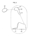
好ましい実施形態において、トランシーバは、読み取り装置によって生成される発振電磁場から電力を受け取る。本発明の一実施形態によるデータ自動記録システムが、図3に例示されている。読み取り装置307は、ハンドヘルドのものであって、ユーザーが簡単に位置を定めて読み取り装置とデータ自動記録装置301との間に有効な結合をもたらしてもよい。読み取り装置には、スクリーン303が含まれていて、受信されたデータを見ることが可能となったりユーザーへのインターフェースを目に見えるメニューで提供したりしてもよい。読み取り装置は、電池で電力が供給されても、受信データを処理する処理装置309のような第2の装置に物理的に接続されてもよい。データは、読み取り装置からデータ処理装置に無線または有線の通信で送られてよい。あるいは、データ処理装置は、データ読み取り装置の一部を構成してもよい。
In a preferred embodiment, the transceiver receives power from an oscillating electromagnetic field generated by a reader. An automatic data recording system according to an embodiment of the present invention is illustrated in FIG. The
読み取り装置には、キーパッド305のような1つ以上の入力が含まれていてもよく、それを介してユーザーは、読み取り装置または読み取り装置への入力データと情報交換をしてもよい。データ処理装置には、1つ以上の入力(手段)311が含まれていて、さらなるデータの組のデータ処理装置への入力を可能としたり、データ処理装置/読み取り装置の機能との情報交換を可能としたりしてもよい。図3における点線の境界で示されるように、データ読み取り装置とデータ処理装置は、同じ装置の一部を構成してもよく、またはそれらは別の装置であってもよい。
The reading device may include one or more inputs, such as a
データ自動記録装置は、トランシーバで受け取られ、読み取り装置が提供する電磁場へとコード化される1つ以上の命令を翻訳する(interpret)受信機論理(receiver logic)をさらに備えていてもよい。データは、電磁場の周波数または振幅を切り替えるか、または当技術分野で周知の他の送信技術でデータ自動記録装置に送られてよい。好ましくは、受信機論理もまた、トランシーバが電磁場から引き出した電力が供給される。 The data logger may further comprise receiver logic that interprets one or more instructions received by the transceiver and encoded into an electromagnetic field provided by the reader. Data may be sent to the data logger by switching the frequency or amplitude of the electromagnetic field or by other transmission techniques known in the art. Preferably, the receiver logic is also supplied with power drawn by the transceiver from the electromagnetic field.
読み取り装置は、1つ以上の命令をデータ自動記録装置に送ってもよい。これらの命令には、センサー106の抽出間隔を設定する命令や、データ転送を開始する命令のほか、校正定数、IDコード、リセット命令、ファームウェアとして実施される制御論理についての更新などのような構成命令(configuration command)も含まれる。
The reader may send one or more instructions to the data logger. These commands include a command for setting the extraction interval of the
あるいは、校正係数、抽出間隔および自動記録装置IDは、製造時に固定される。 Alternatively, the calibration coefficient, the extraction interval, and the automatic recording apparatus ID are fixed at the time of manufacture.
一実施形態において、トランシーバで受け取られる電力が一旦所定のレベルを超えると、トランシーバは、蓄積されたデータを送信し始める。あるいは、トランシーバは、読み取り装置から信号が受け取られるとき送信を開始する。好ましくは、読み取り装置は、識別コードを含むデータ自動記録装置に識別子を送信する。データ自動記録装置は、識別コードがデータ自動記録装置に蓄積されるコードと一致すれば、蓄積されるデータの読み取り装置への送信のみを行う。データ自動記録装置は、(a)1つ以上のデータ読み取り装置に対応する1つ以上の識別コードを蓄積するか、(b)データ読み取り装置がデータ自動記録装置の独自のコードを送信する必要がある。識別コードは、データ記憶手段110に蓄積されてもよい。好ましくは、データ自動記録装置は、そのコードを送信せず、したがって(b)の場合には、読み取り装置はコードを前もって知っておくことが必要となる。これによって、データ自動記録装置に蓄積されるデータが、許可されずにまたは望まれていないのに見られてしまうことを防ぐのに役立つ。あるいは、「チャレンジ‐レスポンス(challenge-response)」プロトコルやその他当技術分野で周知の暗号プロトコルを用いて安全性を高めてもよい。
In one embodiment, once the power received at the transceiver exceeds a predetermined level, the transceiver begins to transmit stored data. Alternatively, the transceiver starts transmitting when a signal is received from the reader. Preferably, the reading device transmits the identifier to the data automatic recording device including the identification code. If the identification code matches the code stored in the data automatic recording device, the data automatic recording device only transmits the stored data to the reading device. The data automatic recording apparatus needs to (a) store one or more identification codes corresponding to one or more data reading apparatuses, or (b) the data reading apparatus needs to transmit a unique code of the data automatic recording apparatus. is there. The identification code may be stored in the
データ自動記録装置は、抽出されたセンサー信号以外のデータをデータ記憶手段110に蓄積する。これには、前述の識別コードが1つ以上および/または、個人識別情報もしくは医療情報のようなユーザーに関係するデータが含まれる。これは、ユーザーが患者であって、データ自動記録装置が患者の生理パラメータを自動記録するのに用いられている、すなわち医療情報が一般の患者識別情報または以前の医療試験の結果または観察ノートである場合に、とりわけ有用である。この、他のデータは、読み取り装置に送られてもよい。
The data automatic recording apparatus accumulates data other than the extracted sensor signal in the
読み取り装置は、異なるデータタイプを受け取るために、異なる識別子を提供するように求められてもよい。例えば、第1の識別子が、データ自動記録装置を駆動して蓄積された生理パラメータデータを送信するように要求され、かつ第2の識別子が、データ自動記録装置を駆動してユーザー/患者情報を送信するように要求される。 The reader may be asked to provide different identifiers to receive different data types. For example, a first identifier is required to drive a data logger and transmit accumulated physiological parameter data, and a second identifier drives a data logger to provide user / patient information. Requested to send.
データ記憶手段110は、好ましくは、電池式のRAM、EEPROM,フラッシュRAMのような不揮発性メモリーであり、より好ましくは、FRAMまたはMRAMである。電源102は、キャパシタか電池である。
The data storage means 110 is preferably a non-volatile memory such as a battery-type RAM, EEPROM, or flash RAM, and more preferably an FRAM or MRAM. The
一実施形態において、センサーの少なくとも1つは温度センサーである。好ましくは、温度センサーはサーミスタである。あるいは温度センサーは、「絶対温度に比例する」電圧源のような、シリコンをベースとする装置であってもよい。感度を高めるために、ブリッジ、フィルターおよび増幅器のような信号処理素子によって信号が増幅されてもよい。 In one embodiment, at least one of the sensors is a temperature sensor. Preferably, the temperature sensor is a thermistor. Alternatively, the temperature sensor may be a silicon-based device, such as a voltage source “proportional to absolute temperature”. To increase sensitivity, the signal may be amplified by signal processing elements such as bridges, filters and amplifiers.
データ自動記録装置のサイズおよび電力要件を最小のものとするために、可能であればデータ自動記録回路は、単一のマイクロチップとして作製される。 In order to minimize the size and power requirements of the data logger, the data logger circuit is made as a single microchip if possible.
1つ以上の生理パラメータを測定するデータ自動記録装置の場合は、装置は、(皮下の)埋め込み装置または着用可能なパッチとして提供される。埋め込み装置としてデータ自動記録装置の筐体は、好ましくは不活性で、埋め込まれた人の免疫系による拒絶反応を防止するのに役立つように被覆される。 In the case of a data logger that measures one or more physiological parameters, the device is provided as an (subcutaneous) implantable device or wearable patch. The housing of the data logger as an embedded device is preferably inert and is coated to help prevent rejection of the implanted person's immune system.
データ自動記録装置によって測定される生理パラメータの例は、温度、圧力、pH、光強度、振動、音圧、向きまたは動きである。データ自動記録装置が測定する生理パラメータの例は、体温、血液のpH、血糖、脈拍数、血圧である。これらのパラメータは、当業界で知られているいかなる方法によって測定されてもよい。 Examples of physiological parameters measured by the data logger are temperature, pressure, pH, light intensity, vibration, sound pressure, direction or movement. Examples of physiological parameters measured by the automatic data recording apparatus are body temperature, blood pH, blood sugar, pulse rate, and blood pressure. These parameters may be measured by any method known in the art.
本発明によるデータ自動記録装置は、体温を測定して基礎体温の自動的な測定を可能とするように構成されてもよい。これによって、何日間にもわたる基礎(最低安静)体温の上昇を探すことによって、ある排卵期から次の排卵期までで排卵時期を推定することが可能となる。これは、活動レベル、環境温度その他が変化する結果、一日を通して急激に変化し得るユーザーの皮膚の温度における短期間の変化とは実質的に独立している。 The data automatic recording device according to the present invention may be configured to measure body temperature and enable automatic measurement of basal body temperature. This makes it possible to estimate the ovulation time from one ovulation period to the next ovulation period by looking for an increase in basal (minimum rest) body temperature over many days. This is substantially independent of short-term changes in the temperature of the user's skin that can change drastically throughout the day as a result of changes in activity levels, environmental temperatures, and the like.
体温は一般的には、ゆっくりと変化するので、データ自動記録処理にはいくつかの改良を施すことができる。最初の改良は、データ自動記録装置でのセンサーデータを圧縮することである。以前測定された温度と今測定されている温度との間の差のデータの流れは、「エントロピーの解読」のための良い候補であるか、またはより低い頻度で起こる値と比べて頻繁に起こる値についてのメモリー要件を最小限化するその他の手段である。これによって、より多くの測定値をデータ自動記録装置に蓄積することが可能となる。 Since body temperature generally changes slowly, several improvements can be made to the automatic data recording process. The first improvement is to compress sensor data in a data logger. The data flow of the difference between the previously measured temperature and the currently measured temperature is a good candidate for “entropy decoding” or occurs more frequently than values that occur less frequently Other means of minimizing memory requirements for values. As a result, more measurement values can be stored in the data automatic recording apparatus.
適切な圧縮機構、例えばフィボナッチ符号化を用いることによって、個々のデータ点を分けることが可能である。データは、循環するバッファ(circular buffer)から簡単に読み取ることができ、エラーはメモリーにおける最後の2つの測定値のみに導入され、それは簡単に捨てることができる。 By using a suitable compression mechanism, such as Fibonacci coding, it is possible to separate individual data points. Data can be easily read from a circular buffer, and errors are introduced only in the last two measurements in memory, which can be easily discarded.
一定の間隔で記録されていないデータは、いつデータ(またはデータ群)が測定されたかの記録(例えばタイムスタンプ)を付けることが必要である。例えば、メモリーが一杯になると、古い値が新しい値で置き換えられ、タイムスタンプによって、いつ各センサー値が測定されたのかが確認される。 Data that is not recorded at regular intervals needs to have a record (eg, a time stamp) of when the data (or group of data) was measured. For example, when the memory is full, the old value is replaced with the new value, and the timestamp confirms when each sensor value was measured.
第2の改善は、最後に測定された値から所定量(例えば、0.01度)を超えて温度が変化するときのみにタイムスタンプを記録するというものである。所定の頻度で測定を行うか、温度の変化についてセンサーを本質的に連続して監視することができる。温度値または温度差はタイムスタンプと一緒に記録してもしなくてもよい。時間差を記録することによって前述のようにデータを圧縮することが可能となる。 The second improvement is that the time stamp is recorded only when the temperature changes beyond a predetermined amount (for example, 0.01 degree) from the last measured value. Measurements can be taken at a predetermined frequency or the sensor can be monitored essentially continuously for changes in temperature. The temperature value or temperature difference may or may not be recorded with the time stamp. By recording the time difference, the data can be compressed as described above.
しばしば起こるセンサー値における急激で小さな変動は、排卵時期を判定する温度測定などにおいては、重要ではない。そのような場合、非常に簡単なA/Dコンバーターまたは抽出保持回路を用いて、温度値を比較し、最後の値と現在の値との差を測定することができる。メインのA/Dコンバーターは、差が所定の量より大きくなって、タイムスタンプおよび/または温度値がデータ記録装置に蓄積されるようになるまでスリープ状態に保たれる。この構成はさらに、スリープ時間を最小として、メインのA/Dコンバーターが、大きく急激な温度変動の期間に頻繁にスリープから解除され過ぎるのを回避するように改良される。これらの構成は、データ自動記録装置でメモリーと電力の双方を節約するのに役立つ。 The frequent small fluctuations in sensor values that are often not important, such as in temperature measurements that determine ovulation time. In such a case, a very simple A / D converter or extraction hold circuit can be used to compare the temperature values and measure the difference between the last value and the current value. The main A / D converter is kept in a sleep state until the difference is greater than a predetermined amount and time stamps and / or temperature values are accumulated in the data recording device. This configuration is further improved to minimize sleep time and to avoid the main A / D converter from being released too often from sleep during periods of large and rapid temperature fluctuations. These configurations help to save both memory and power in the data logger.
第3の改善は、時間を経て得られる値を平均化することである。これは、センサー値における急激な変動についての情報を捨て、本質的に高周波「ノイズ」を取り除く効果がある。これは、スライドする窓を用いて達成することができ、例えば循環するバッファは、14ビットの解像度で測定される最後の測定値を16保持することができ、そして測定値の16ビット平均は、メモリーに蓄積される。これらの14ビット測定値の合計は、18ビットの数字であるが、A/D信号の最も小さなビットにおけるノイズのガウス分布を想定すると、16の平方根16=4の信号:ノイズの向上が見られ、18ビットの数の上位16ビットのみを用いることで14ビットの測定値から16ビットの値がもたらされる。他のビット長およびバッファのサイズを用いることもできる。 A third improvement is to average the values obtained over time. This has the effect of discarding information about sudden fluctuations in sensor values and essentially removing high frequency “noise”. This can be achieved with a sliding window, for example a circular buffer can hold 16 last measurements measured at 14-bit resolution, and the 16-bit average of the measurements is Accumulated in memory. The sum of these 14-bit measurements is an 18-bit number, but assuming a Gaussian distribution of noise at the smallest bit of the A / D signal, a 16 square root 16 = 4 signal: an improvement in noise is seen. Using only the upper 16 bits of the 18-bit number results in a 16-bit value from the 14-bit measurement. Other bit lengths and buffer sizes can be used.
さらなる改善は、平均化する計算においてバッファの最大および最小測定値を含めないことである。これは、範囲外の測定値の影響を最小限とするのに役立つ。いくつかの測定値を選択的に除外することもでき、例えば16のうち中間の12の測定値のみとして範囲外の測定値の短い期間の影響をさらに低減する。 A further improvement is not to include the buffer maximum and minimum measurements in the averaging calculation. This helps to minimize the effects of out-of-range measurements. Some measurements can also be selectively excluded, eg, only the middle 12 measurements out of 16 to further reduce the effect of short periods of measurements outside the range.
生理中に起こるある生理上の徴候を監視することによって、自然な家族計画を進めることができる。最も普通に観察される徴候は、生理出血、子宮頸粘液の変化および体温の変化である。 By monitoring certain physiological signs that occur during menstruation, natural family planning can proceed. The most commonly observed signs are menstrual bleeding, cervical mucus changes and body temperature changes.
カレンダー利用のリズム式避妊法が、受精の可能性を認識する方法として最も古くから最も広く使われている。カレンダーに記録することで、精子によって卵が受精する状態にある期間とその始まりを女性が推定することが可能となる。受精期間の計算は、1)次の生理が始まる前の14日目(プラスマイナス2日)に排卵が起こり、2)精子は2日から3日生き続け、3)卵子または卵は24時間生き続けるという3つの仮定からなされる。 Calendar-based rhythmic contraception has long been the most widely used method for recognizing fertility. By recording in the calendar, it becomes possible for a woman to estimate the period during which an egg is fertilized by sperm and its beginning. The fertilization period is calculated as follows: 1) Ovulation occurs on the 14th day (plus or minus 2 days) before the next period begins, 2) The sperm continues to live for 2 to 3 days, 3) The egg or egg lives for 24 hours Three assumptions are made to continue.
基礎体温(BBT)法は、朝最初に、好ましくは毎朝同じ時間に、口内で検温し、それらの温度をグラフにつけることで広く行われている。前の7日のいずれよりも体温が3日続けて高くなった後、排卵が起こっていると一般には示されている。この方法を用いると、排卵を予想することはできないが、一度それが起こると識別することができる。この方法は、女性が妊娠しない時期がいつ始まったかを識別するのに最も有用である。 The basal body temperature (BBT) method is widely performed by taking a temperature in the mouth at the beginning of the morning, preferably at the same time every morning, and putting these temperatures on a graph. It is generally indicated that ovulation has occurred after 3 consecutive days of body temperature higher than any of the previous 7 days. Using this method, ovulation cannot be predicted, but it can be identified once it has occurred. This method is most useful in identifying when a time when a woman does not become pregnant has begun.
子宮頸粘液の変化は、生理が不規則であっても、排卵の起こるたいていの女性の間ではっきりとしたパターンがある。子宮頸粘液を評価するために、女性は彼女の膣口から粘液を得る。粘液をチェックすることで、女性はそれが湿っていると感じるか乾いていると感じるかを判定する必要がある。粘着性、弾性および湿り具合といった粘液の質によって、彼女が周期においてどこにいるのかが示唆される。通常、最後の「滑りやすく湿った」粘液の日の前またはその日の間に、卵の放出が起こる。粘液が、熱の通っていない卵白の特性を有するときが、妊娠する時期である。膣潤滑剤や、膣洗浄を用いるとこれらの特性を認識するのがより困難となる。 Cervical mucus changes have a pronounced pattern among most women with ovulation, even if their physiology is irregular. To evaluate cervical mucus, a woman gets mucus from her vaginal opening. By checking mucus, women need to determine whether they feel wet or dry. The quality of the mucus, such as stickiness, elasticity and wetness, suggests where she is in the cycle. Usually, egg release occurs before or during the last “slippery and moist” mucus day. The time when the mucus becomes pregnant is when it has the characteristics of a non-heated egg white. Using vaginal lubricants and vaginal lavage makes it more difficult to recognize these properties.
種々のグラフ付け方法は、単独でまたは組み合わせて用いられる。普通の技法は、女性が粘液の変化と基礎体温を記録することである。女性によってはまた、生理痛を認め、それを記録するが、それには、重苦しさ、腹部の腫れ、直腸の痛みまたは不快感、および、下腹部の痛みまたは不快感が含まれる。痛みは、排卵の直前、排卵期間中または排卵後に起こり得る。 Various graphing methods may be used alone or in combination. The usual technique is for women to record changes in mucus and basal body temperature. Some women also recognize and record menstrual pain, which includes severe pain, abdominal swelling, rectal pain or discomfort, and lower abdominal pain or discomfort. Pain can occur immediately before, during or after ovulation.
ここに記述されているデータ記録装置は、自動的な体温の監視を行うことができ、一方、女性は、粘液の変化のような主観的なパラメータの記録を自分で行う必要がある。これらの追加の主観的なパラメータを(前述のような)読み取り装置または温度データが送られるデータ処理装置に入力し、利用可能な時のみ(それが利用可能であることが必要ではないが)それを用いることによって、それを温度データや時間/日付データと選択的に組み合わせて、将来の排卵日および/または、主観的なパラメータの変化が期待される将来の日付を推定して、最も必要であるように思われるときに女性がそれらを監視することが奨励される。 The data recording device described herein can perform automatic body temperature monitoring, while women need to record subjective parameters such as mucus changes themselves. These additional subjective parameters are entered into a reader (as described above) or a data processor to which temperature data is sent and only when it is available (although it does not have to be available) Is used in combination with temperature data and time / date data to estimate future ovulation dates and / or future dates where subjective parameter changes are expected and Women are encouraged to monitor them when it seems to be.
これらの追加の主観的なパラメータは、体温は排卵後に上昇する一方、他の主観的なパラメータは排卵前に変化するという点において重要である。体温のみを用いて妊娠する期間を特定しようとすると、不確実な期間がより広くなるが、それは、サイクルにおける排卵後の部分がはっきりと定義されていて(一般的には生理前およそ10日〜12日)、サイクルによって長さがあまり違わないからである。したがって、体温を記録することでこの期間を識別することができる。しかしながら、サイクルの排卵前の部分は、サイクルによって長さが異なる。生理の初日についてのデータを加えることで、2つ目の全く客観的なパラメータが加えられ、排卵のタイミングの推定が改善できる。 These additional subjective parameters are important in that body temperature increases after ovulation, while other subjective parameters change before ovulation. Trying to determine the period of pregnancy using only body temperature results in a wider uncertainty period, which is a well-defined part of the cycle after ovulation (generally around 10 days before menstruation) 12)), because the length does not differ greatly depending on the cycle. Therefore, this period can be identified by recording the body temperature. However, the length of the part of the cycle before ovulation varies depending on the cycle. By adding data about the first day of menstruation, a second totally objective parameter is added, which can improve the estimation of ovulation timing.
たとえば、子宮頸粘液の質についての情報を加えることによって、妊娠できる期間の始まりをより正確に測定できる。しかしながら、子宮頸粘液の質は、女性によっては、とりわけ前日に性交した後では、確認するのが非常に困難である。さらなる生理上のデータが提供されさえすれば、それを用いるのが最も有益であり、体温の測定値および、さらなるデータが提供されないときに妊娠する期間の始まりを計算するタイミングに、システムが依存する。同様に、唾液の質、胸の柔らかさ、生理痛およびホルモンの測定値のようなその他のパラメータが観察されるならば、それらを全て加えることもできる。 For example, by adding information about the quality of cervical mucus, the beginning of a period of pregnancy can be measured more accurately. However, the quality of cervical mucus is very difficult to confirm for some women, especially after intercourse the previous day. As long as additional physiological data is provided, it is most beneficial to use it, and the system relies on temperature measurements and the timing of calculating the beginning of a pregnancy period when no additional data is provided . Similarly, if other parameters such as saliva quality, breast softness, menstrual pain and hormone measurements are observed, they can all be added.
体温を監視するデータ自動記録装置は、女性に注射されるか小さな手術をして挿入される埋め込み装置の形をとってよい。データ自動記録装置は、好ましくは、データ自動記録装置によって記録される温度が正確に体の中心の温度を反映するように、腹部または上腕の内側に挿入される。あるいはデータ自動記録装置をパッチ、着用可能なバンドまたは(下着のような)衣類に組み込むこともできる。これは以下に記述されるように実施される。 A data logger that monitors body temperature may take the form of an implanted device that is injected into a woman or inserted with minor surgery. The data logger is preferably inserted inside the abdomen or upper arm so that the temperature recorded by the data logger accurately reflects the temperature at the center of the body. Alternatively, data loggers can be incorporated into patches, wearable bands or clothing (such as underwear). This is done as described below.
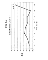
図6Aは、温度データ記録装置を用いて基礎体温を推定する利点を例示する。図6Aのプロットは、本発明の実施形態による試作のデータ自動記録装置によって、ユーザーが寝ている間に夜通し周期的に自動記録したデータから推定される日常の基礎体温についてのものである。動きが盛んな期間に取られた温度測定値は無視され、データ自動記録装置からの残りの温度データが処理されて範囲外の温度測定値が除外された。そのとき残っている温度測定値の平均が取られて、測定された温度における短期の変動が除去された。 FIG. 6A illustrates the advantage of estimating basal body temperature using a temperature data recording device. The plot in FIG. 6A is for daily basal body temperature estimated from data automatically recorded throughout the night while the user is sleeping by the prototype automatic data recording apparatus according to the embodiment of the present invention. Temperature readings taken during periods of high activity were ignored and the remaining temperature data from the data logger was processed to exclude out-of-range temperature readings. The remaining temperature measurements were then averaged to remove short-term fluctuations in the measured temperature.
図6Bのプロットは、図6Aのプロットと同じ日に通常の技法を用いて推定された基礎体温についてのものであり、耳体温計(ブラウン(Braun, 会社名)・サーモスコープ(ThermoScope, 商品名))で起床時午前6時30分にユーザーが2つの測定を行った。試作のデータ自動記録装置は、(プロットにおいて矢印で示される)排卵日をはっきりと検出しており、一方通常のアプローチを用いて検出するのは非常に困難である。データ自動記録装置を用いることで、毎朝早くユーザーが起床して体温を測りそれを記録簿に書きとめる必要もなくなる。 The plot in FIG. 6B is for basal body temperature estimated using normal techniques on the same day as the plot in FIG. 6A. ) The user made two measurements at 6:30 am when waking up. Prototype data loggers clearly detect the date of ovulation (indicated by the arrows in the plot), while they are very difficult to detect using conventional approaches. By using the automatic data recording device, it is not necessary for the user to get up early every morning to measure body temperature and write it down in the record book.
図7は、図6Aに示されるデータを収集するのに用いられた試作のデータ自動記録装置の回路図を示す。 FIG. 7 shows a circuit diagram of a prototype automatic data recording apparatus used to collect the data shown in FIG. 6A.
データ自動記録装置からのデータの規則的な読み取りについて設計(し、排卵を予想)することで、読み取り装置が生成する電磁場から得られる電力によって電源が規則的に充電される。したがって、装置のための電源は、比較的小さい。装置のサイズが小さくなることと、データ送信の間無線で充電が行われることとがこのように組み合わさって、実際に埋め込み装置としての装置を実施することが可能となり、あるいは、装置を、通常の絆創膏やバンドエイドと同じように皮膚に固着できる小さな粘着パッチに別個に組み込むことが可能となる。 By designing (and anticipating ovulation) for regular reading of data from the data logger, the power supply is regularly charged by the power obtained from the electromagnetic field generated by the reader. Thus, the power source for the device is relatively small. This combination of reduced device size and wireless charging during data transmission makes it possible to actually implement the device as an embedded device, or It can be separately incorporated into a small adhesive patch that can be fixed to the skin in the same manner as a bandage or band aid.
一実施形態において、データ自動記録装置には、制御論理、タイミング、測定、電力制御、温度検知および無線通信を含む集積回路が含まれており、それを、電力を蓄積するリチウムポリマー電池およびアンテナに結合する。データ自動記録装置は、体温を測定するので、装置がさらされる温度範囲は非常に狭く、そうしてサンプリング周波数のための超低電力アナログタイミングが、R−C時定数を用いて受け入れ可能な精度で可能である。電力供給の経時変化もまた周期的に測定することができ、そうして測定の頻度を自動記録する間に調節することができる。一般的には、データ自動記録装置は、所定の頻度(たとえば10分ごと)で温度を記録し、そしてこれをメモリーに記録する。 In one embodiment, the data logger includes an integrated circuit that includes control logic, timing, measurement, power control, temperature sensing, and wireless communications that can be connected to a lithium polymer battery and antenna that store power. Join. Since the data logger measures body temperature, the temperature range to which the device is exposed is very narrow, so the ultra-low power analog timing for the sampling frequency is acceptable with the RC time constant. Is possible. Changes in power supply over time can also be measured periodically and thus adjusted during automatic recording of the frequency of measurements. In general, the automatic data recorder records the temperature at a predetermined frequency (for example, every 10 minutes) and records it in a memory.
排卵時期を判定するシステムは、ここに記述されるいずれかの形をしていて、温度を測定するように構成されるデータ自動記録装置と、ここに記述されているいずれかの形をしているデータ読み取り装置と、データ処理装置とを備えてよい。あるいは、データ自動記録装置は、受動送信が可能であって、データ読み取り装置と両立して使うことのできる周知の温度データ自動記録装置のいずれであってもよい。データ自動記録装置は、蓄積されたデータを受動送信によってデータ読み取り装置に送信する。データ読み取り装置とデータ処理装置は、何らかの周知の方法によって通信してもよい。 A system for determining ovulation time may take any of the forms described herein, and a data logger configured to measure temperature and any of the forms described herein. A data reading device and a data processing device. Alternatively, the data automatic recording device may be any known temperature data automatic recording device that can perform passive transmission and can be used in combination with the data reading device. The data automatic recording device transmits the accumulated data to the data reading device by passive transmission. The data reading device and the data processing device may communicate by any known method.
読み取り装置は、ディスプレイと、ユーザー入力性能(user input capability)とを有していて、ユーザーが、データ自動記録装置から受け取られるデータの表やグラフを見たり、および/または、ユーザーが、図形メニューのシステムで情報交換したりすることが可能であってもよい。読み取り装置は、データ処理装置と接続されていてもよく、またはデータ処理装置は、読み取り装置の一部を構成していてもよい。システムには、データ自動記録装置から受け取られるデータを処理して、女性ユーザーの排卵時期を指示することが可能であるという面があることが重要であるにすぎない。データ処理装置は、単純に、データ処理を行うように設計されているソフトウェアを支援するパソコンであってよい。 The reader has a display and user input capability so that the user can view tables and graphs of data received from the data logger and / or the user can select a graphical menu. It may be possible to exchange information with other systems. The reading device may be connected to the data processing device, or the data processing device may form part of the reading device. It is only important that the system has the aspect that it can process the data received from the data logger and indicate the ovulation time of the female user. The data processing device may simply be a personal computer that supports software designed to perform data processing.
データ読み取り装置かデータ処理装置かには、女性ユーザーについて少なくとも1つの別の生理データを入力する入力手段が含まれている。データ処理装置は、体温データを(子宮頸粘液の質、血液または尿からのホルモン試験の結果その他のような)別の生理データと組み合わせて、前述のようなまたは周知の排卵検出の原理のいずれかに従って排卵時期を指示することができる。 The data reading device or the data processing device includes an input means for inputting at least one other physiological data for the female user. The data processor combines the body temperature data with other physiological data (such as cervical mucus quality, hormonal test results from blood or urine, etc.), either as described above or the well-known ovulation detection principle. The ovulation time can be instructed accordingly.
好ましくは、読み取り装置は、適度に近いところで作動させるとき埋め込み装置と双方向通信を行う、持ち運び可能な無線読み取り装置からなる。ユーザーインターフェースには、生理日や子宮頸液質のようなデータを入力する多数のボタン、および、測定値についてプロンプトで指示を求めたり、埋め込み装置や読み取り装置の電池チャージのようなパラメータを指示したりする簡単なLCDディスプレイが含まれている。同様に、もしデータ処理装置がそのような入力を受け取るように設計されているならば、ユーザーはさらなる生理データを、直接データ処理装置に入力してもよく、データ処理装置がパソコンであるならば、これはユーザーにとって都合がよい。読み取り装置自体は、(読み取り装置および/またはデータ処理装置に蓄積される)以前に記録されたデータに基づいて排卵時期を推定する能力があってもよく、次の排卵までの期待される日数をユーザーに表示する能力があるのも適切である。プライバシーを理由として、装置は、キーを操作してそれがデータを与えられている埋め込み装置と最近接触していなければ、妊娠の可能性についての情報を、好ましくは表示しない。 Preferably, the reader comprises a portable wireless reader that performs two-way communication with the implant device when operated at a reasonably close distance. The user interface includes a number of buttons for entering data such as menstrual days and cervical fluids, prompting for measurements, and parameters such as battery charge for implanters and readers. A simple LCD display is included. Similarly, if the data processing device is designed to receive such input, the user may enter additional physiological data directly into the data processing device, if the data processing device is a personal computer. This is convenient for the user. The reader itself may be capable of estimating the ovulation time based on previously recorded data (stored in the reader and / or data processing device) and may determine the expected number of days until the next ovulation. It is also appropriate to have the ability to display to the user. For privacy reasons, the device preferably does not display information about the possibility of pregnancy unless it has operated a key and it has recently been in contact with the implanted device for which data is being provided.
読み取り装置は、USBポート(または有線もしくは無線のその他適切な接続形態)を含んでいて、パソコンに接続が可能であってもよい。これによって、(a)読み取り装置の内部電池の充電および/または(b)データの蓄積のため、データのさらなる処理のため、データの表示のためまたは単純にコンピュータがシステムにおいて温度データの処理を行うために、コンピュータからのまたはコンピュータへのデータ送信が可能になる。読み取り装置またはデータ処理装置が、期待される排卵のモデルに適合するデータを見つけられないか、さらなるユーザーとの情報交換が必要であるとき、ユーザーにそれをパソコンに接続するように促すことができる。 The reading device may include a USB port (or other suitable connection type such as wired or wireless) and be connectable to a personal computer. This allows (a) charging of the internal battery of the reader and / or (b) storage of data, further processing of the data, display of data or simply a computer processes the temperature data in the system. This allows data transmission from or to the computer. When a reader or data processor cannot find data that fits the expected ovulation model or needs more information exchange with the user, it can prompt the user to connect it to the computer .
装置は、コンピュータにはUSB「ドライブ」蓄積装置として現われ、装置のためのソフトウェアとマニュアルがドライブで利用でき、そうすると、別のソフトウェア(例えばCD)を装置と共に持ち運ぶことが必要でなくなる。ソフトウェアによってさらに拡張されたユーザーインターフェースが提供され、それはソフトウェアとファームウェアの更新を行うためにインターネットに接続するように動作可能であってもよい。オプションとして、ユーザーのデータは、第三者、例えば開業医が分析するためにインターネットでアップロードすることができる。 The device appears to the computer as a USB “drive” storage device, and the software and manual for the device are available on the drive, so that it is not necessary to carry additional software (eg, a CD) with the device. A further extended user interface is provided by the software, which may be operable to connect to the Internet to perform software and firmware updates. Optionally, the user's data can be uploaded over the internet for analysis by a third party, eg a practitioner.
コンピュータを読み取り装置とのインターフェースの面からみると、システムを、子宮頸液の質のような、より主観的な生理パラメータの測定におけるユーザーのためのトレーニングシステムとして活用することが可能となるが、それは、トレーニングソフトウェアが体温履歴やその他のユーザーのデータを組み込むことができるからである。これによって、身体について第三者から教えてもらうこと(これはしばしば出過ぎたことであったり困ったことであったりすると考えられる)にユーザーが頼ることが少なくなる。 From the point of view of the computer interface with the reader, the system can be used as a training system for users in measuring more subjective physiological parameters, such as cervical fluid quality, This is because the training software can incorporate body temperature history and other user data. This reduces the user's reliance on being taught by a third party about the body (which is often thought to be too much or troubled).
ユーザーがこれらの追加のパラメータを測定することにより精通するにつれ、排卵予想についての統計的なモデルが変更されて、これらの観察により重点が置かれることになる。これによって、避妊のために性交を抑制しなければならない排卵期ごろの「安全期間」を漸進的に減らしていくことが可能となる。 As the user becomes more familiar with measuring these additional parameters, the statistical model for ovulation prediction will be modified to focus more on these observations. This makes it possible to gradually reduce the “safe period” around the ovulation period when sexual intercourse must be suppressed for contraception.
ここに記述されるデータ自動記録装置は、図4および図5に示されるような着用可能な粘着パッチ407、503に組み込まれる人間または動物の体温(人体または動物の体の温度)データ自動記録装置である。粘着剤411は、周知の皮膚粘着剤から選択され、好ましくは、ユーザーの皮膚401との有害な反応の危険を最小限とするようにアレルギー反応が低い。パッチは、好ましくはデータ自動記録装置403、405を袋の中に入れて保持し、それによってデータ自動記録装置を取り除いて、例えば粘着剤が粘性を失ったりユーザーが新しいパッチを望んだりするときに便利なように、新しいパッチに据え付けることが可能となる。図5は、データ自動記録装置501を取り除いたり据え付けたりする開口507を示す。あるいは、データ記録装置は、袋の中に密閉できるものであり、それはパッチとデータ自動記録装置が使い捨てであるならば都合がよい。
The data automatic recording device described here is a human or animal body temperature (human body or animal body temperature) data automatic recording device incorporated in a wearable
好ましい実施形態において、パッチは、おおよそ円形であって、直径が約2cmで肌色である。体温センサーを温度の環境的な変化から熱的に絶縁するために、パッチは、データ自動記録装置の、データ自動記録装置が体に対して保持される側と反対の部分を覆って広がる(柔らかい発泡体の裏張りのような)断熱領域405を有する。パッチには、開口509があって、それを通してデータ自動記録装置の伝熱鋲409、505が突出し、パッチが固定される体と物理的に接触する。図5において、これは、データ自動記録装置がパッチに挿入されるための開口507の一部を形成する。
In a preferred embodiment, the patch is approximately circular, has a diameter of about 2 cm and is flesh-colored. To thermally insulate the body temperature sensor from environmental changes in temperature, the patch spreads over the portion of the data logger opposite the side where the data logger is held against the body (soft It has an insulating area 405 (such as a foam backing). The patch has an
データ自動記録装置が伝熱鋲を有していない場合には、パッチ(および可能であるならばデータ自動記録装置のシェル)が、体温センサーと、パッチ/シェルの上の他の部分よりも体自体との関係においてより伝熱性が高いことが一般には望ましい。これは、パッチ/シェルにおいて用いられる材料を選択することで、および/またはパッチ/シェルを、温度センサーの上の領域において材料がより薄くなるように作製することによって達成される。 If the data logger does not have a heat exchanger, the patch (and the data logger's shell, if possible) can be placed on the body more than the body temperature sensor and the rest of the patch / shell. It is generally desirable that the heat transfer be higher in relation to itself. This is accomplished by selecting the material used in the patch / shell and / or by making the patch / shell so that the material is thinner in the region above the temperature sensor.
前述のパッチの構成は、殺菌した使い捨ての装置として都合よく供給される。 The patch configuration described above is conveniently supplied as a sterilized disposable device.
あるいは、データ自動記録装置は、(腕周りに着用されるような)バンドまたは衣料品に組み込まれるか、ストラップやバンドを用いてデータ自動記録装置を適切な位置に保持する。好ましくは、バンドは上腕の周りに着用されて、温度センサーが腕の内側の脇の下の近くに位置する。体温の小さな変化を正確に測定することができるためには、ユーザーがバンドを装着し直すごとにユーザーの体の同じ位置(測定点)にデータ自動記録装置が再度位置付けられることがとりわけ重要である。したがって、バンド内に保持されるデータ自動記録装置を正しく位置付けるようにユーザーの助けとなる印がバンドに付けられていてもよい。長期間着用しても快適で良好な断熱材であるネオプレンがバンドの材料としてとりわけ適切である。 Alternatively, the data logger is incorporated into a band or apparel (such as worn around the arm) or uses a strap or band to hold the data logger in place. Preferably, the band is worn around the upper arm and the temperature sensor is located near the armpit inside the arm. In order to be able to accurately measure small changes in body temperature, it is especially important that the data logger is repositioned at the same position (measurement point) on the user's body each time the user re-wears the band. . Therefore, the band may be marked to help the user to correctly position the data logger device held in the band. Neoprene, which is a comfortable and good thermal insulator even when worn for a long time, is particularly suitable as a material for the band.
バンドにおける輪の中に、いくつかの温度センサーが保持されてもよい。こうすれば、バンドが回転してユーザーが上手く位置づけできなくとも、その影響を緩和するのに役立つ。一般的には、バンドが着用される(例えば)腕の周りの温度には違いがあり、その違いを既知とできる。この違いを測定して、データ自動記録装置に、より好ましくは温度測定値が送られて処理されるデータ処理装置に、特定のユーザーのプロフィールとして蓄積することができる。そのプロフィールによって、各センサーからの温度測定値が、後で腕の周りの位置と関係付けられてどのセンサーが「測定点」に最も近いかが判定される。バンドが交換されるごとに測定点の温度をより正確に測定するために、既知の温度プロフィールを用いて温度測定値間を補完することがさらに望ましい。これらの計算は、データ処理装置で行うことができる。 Several temperature sensors may be held in a ring in the band. This will help mitigate the effects of the band rotating and not being positioned well by the user. In general, there is a difference in the temperature around the arm (for example) where the band is worn, and the difference can be known. This difference can be measured and stored as a profile for a particular user in a data logger, more preferably in a data processing device where temperature measurements are sent and processed. The profile determines which sensor is closest to the “measurement point”, with temperature measurements from each sensor later associated with a position around the arm. In order to more accurately measure the temperature at the measurement point each time the band is changed, it is further desirable to supplement between temperature measurements using a known temperature profile. These calculations can be performed by a data processing device.
図3、図4および図5に例示される実施形態において、温度センサーとアンテナがデータ自動記録装置自体の本体に組み込まれる。この実施形態において、温度センサーの上にデータ自動記録装置のシェルの伝熱部があるか、図示されているような、温度センサーを体に結合する伝熱鋲がある。しかしながら、温度センサーは、データ自動記録装置の本体の外側にあってデータ自動記録装置とワイヤーで接続されている。同様に、アンテナも、おそらくはデータおよび電力の転送を向上するように、データ自動記録装置の本体の外にある。温度センサーおよび/またはアンテナは、パッチ/バンドと一体化されていて、ワイヤーでデータ自動記録装置に接続されている。 In the embodiment illustrated in FIGS. 3, 4 and 5, the temperature sensor and the antenna are incorporated into the body of the data logger itself. In this embodiment, there is a heat transfer part of the shell of the data logger on the temperature sensor, or there is a heat transfer rod that couples the temperature sensor to the body, as shown. However, the temperature sensor is outside the main body of the data automatic recording device and is connected to the data automatic recording device by a wire. Similarly, the antenna is also outside the body of the data logger, possibly to improve data and power transfer. The temperature sensor and / or antenna is integrated with the patch / band and connected to the data logger by a wire.
好ましくは、データ自動記録装置自体が密閉したシェルの中に包みこまれていて、データ自動装置の構成要素を衝撃や液体や腐食から保護する。異なるユーザーが装置を再使用できるように、自動記録装置がオートクレーブで殺菌できることもまた有利である。好ましくは、シェルは、シリコーンまたはその他の不活性材料の外側層を有する。温度センサーの上のシリコーン層が薄く(おそらくは0.1mm)またシェルのその他の領域上ではシリコーン層が厚い(おそらくは0.5mm)というように、シリコーンはシェルの上で厚みに変化があってもよい。シリコーンの厚い層は、センサーを断熱するのに役立つ。温度センサーの上でシリコーンに金属粒子が混入されて、その領域でのシリコーンの伝熱性が高められていてもよい。 Preferably, the data logger itself is encased in a sealed shell to protect the components of the data logger from impacts, liquids and corrosion. It is also advantageous that the automatic recording device can be sterilized with an autoclave so that different users can reuse the device. Preferably, the shell has an outer layer of silicone or other inert material. Even if the silicone varies in thickness on the shell, the silicone layer on the temperature sensor is thin (probably 0.1 mm) and the silicone layer is thick on other areas of the shell (probably 0.5 mm). Good. A thick layer of silicone serves to insulate the sensor. Metal particles may be mixed into the silicone on the temperature sensor, and the heat conductivity of the silicone in that region may be improved.
シリコーンやその他の保護材料は、好ましくは、射出成型可能であり、インサート成型可能であり、防水性があり、および/または生体適合性がある。 Silicone and other protective materials are preferably injection moldable, insert moldable, waterproof and / or biocompatible.
前述のように、データ自動記録装置は、データ自動記録装置のシェル/シリコーン中に幾分突出するかそれを貫通する高伝熱材料(例えば金属)の鋲を有していて、データ自動記録装置の温度センサーと、それが適用される体との間の熱結合が向上するものであってもよい。 As mentioned above, the data logger has a ridge of high heat transfer material (eg, metal) that protrudes somewhat into or through the shell / silicone of the data logger, and the data logger The thermal coupling between the temperature sensor and the body to which it is applied may be improved.
体の中心の温度を推定することが求められるが、体の外部の点で測定が行われる場合は、皮膚温度の簡単な測定を改良することができる。皮膚温度が伝熱パッチの下で測定され、かつ絶縁体の外面の温度も測定される(すなわち2つの測定値を得る)なら、皮膚温度と体の中心の温度との間の差を推定することが可能である。最も簡単にこれを実施するには、2つのセンサーの温度差に一定の係数を適用し、すなわち Tcore = Tskin + k (Tskin - Touter) とする。より複雑ではあるが正確な方法は、周囲の温度が皮膚温度よりも高い場合と低い場合とを考慮し、また補正を非線形関数とすることである。好ましくは、そのような補正は、結果として得られる体の中心の温度の推定値をデータ自動記録装置に蓄積しさえすればよいように、データ自動記録装置で適用される。あるいは、双方の温度データを蓄積して、温度データが送られるデータ処理装置で補正を適用してもよい。 Although it is required to estimate the temperature at the center of the body, simple measurements of skin temperature can be improved if measurements are taken at points outside the body. If skin temperature is measured under a heat transfer patch and the outer surface temperature of the insulator is also measured (ie, taking two measurements), estimate the difference between skin temperature and body center temperature It is possible. The simplest way to do this is to apply a constant factor to the temperature difference between the two sensors: Tcore = Tskin + k (Tskin-Touter). A more complex but accurate method is to consider whether the ambient temperature is higher or lower than the skin temperature and make the correction a non-linear function. Preferably, such correction is applied at the data logger so that the resulting body center temperature estimate only needs to be stored in the data logger. Alternatively, the correction may be applied by a data processing apparatus that accumulates both temperature data and sends the temperature data.
様々な外部温度状況のもとで、(いずれの従来技法で測定されても)体の中心の温度に対してそのようなパッチ装置を校正すること(calibrating)によって、より正確な補正システムが案出される。あるいは、データからおよそ一定の体の中心の温度を得るために必要な補正機能を決定するという目的で、以下の方法のいずれかによって校正(calibration)が行われる。
1.パッチを横切る既知の温度勾配を適用し、温度計2つの反応を測定する。
2.ユーザーがパッチを着用する間の温度範囲に、外部温度センサーを露呈する。適用される温度は、体温が温度変化に反応できるよりも速く変化することが重要である。
3.測定される皮膚の温度に比べて外部温度の自然で急激な変化について、使用の間の温度測定値を分析する。この方法は、好ましくは、データ自動記録装置で行われ、環境の変化に応答して補正機能を継続的に調節するのに用いられる。
By calibrating such a patch device against the temperature of the center of the body (measured by any conventional technique) under various external temperature conditions, a more accurate correction system is proposed. Is issued. Alternatively, calibration is performed by any of the following methods for the purpose of determining a correction function necessary to obtain an approximately constant body center temperature from the data.
1. A known temperature gradient across the patch is applied and two thermometer responses are measured.
2. An external temperature sensor is exposed to the temperature range while the user wears the patch. It is important that the applied temperature changes faster than the body temperature can respond to temperature changes.
3. Analyze temperature measurements during use for natural and rapid changes in external temperature compared to the measured skin temperature. This method is preferably performed in a data logger and is used to continuously adjust the correction function in response to environmental changes.
一実施形態において、データ読み取り装置または(読み取り装置が接続される)データ処理装置で校正の計算が以下のように行われる。
1.データ読み取り装置は、データ自動記録装置に命令を送り、それに校正モードに入るように指示する。
2.校正処理が開始され、データ自動記録装置は、温度センサーからの温度データをリアルタイムで送信する。
3.データ読み取り装置、またはデータ読み取り装置が接続されるデータ処理装置が、補正関数を計算する。
4.データ読み取り装置が、皮膚および外部温度センサーの値から体の中心の温度を外挿して推定するのに用いられるデータ自動記録装置に校正関数のパラメータを送信する。
In one embodiment, calibration calculations are performed as follows on a data reader or data processor (to which the reader is connected).
1. The data reader sends a command to the data logger and instructs it to enter the calibration mode.
2. The calibration process is started, and the data automatic recording device transmits the temperature data from the temperature sensor in real time.
3. The data reader or the data processor to which the data reader is connected calculates the correction function.
4). The data reader sends the calibration function parameters to a data logger that is used to extrapolate and estimate the temperature at the center of the body from the skin and external temperature sensor values.
校正係数は、データ自動記録装置に蓄積される(校正の計算が読み取り装置/データ処理装置で行われるならば、おそらくは、データ読み取り装置から送信された後)。データ自動記録装置シェル、および/または、パッチ/バンドの、熱特性もしくはその熱特性を表わす派生的な数字が、測定されたデータを処理するのに用いられるデータ自動記録装置またはデータ読み取り装置/処理装置に蓄積される。熱特性は、校正処理中に測定されるか、データ自動記録装置シェルおよび/またはパッチ/バンドが既知の特性を有する材料を用いているならば、利用が可能である。これらの特性を知ることで、例えば、データ処理装置が、体の中心の温度を外挿して推定するのに用いることができる、データ自動記録装置およびその封入物を横切る論理上の温度勾配を、計算することができるようになる。 The calibration factor is stored in the data logger (if the calibration calculation is done in the reader / data processor, perhaps after being sent from the data reader). A data logger or data reader / process in which the data logger shell and / or the patch / band thermal properties or derivative numbers representing the thermal properties are used to process the measured data Accumulated in the device. Thermal properties are measured during the calibration process or can be utilized if the data logger shell and / or patch / band uses materials with known properties. Knowing these characteristics, for example, the logical temperature gradient across the data logger and its inclusion, which the data processor can use to extrapolate and estimate the temperature at the center of the body, Be able to calculate.
その他のセンサーの型については、関連する物理特性が代わりに蓄積される。例えば、データ自動記録装置が組み込まれる封入物の音または光送信特性が蓄積される。前述の校正原理は、他の型のセンサーによる他の物理パラメータの校正測定値に等しく適用される。 For other sensor types, the relevant physical properties are accumulated instead. For example, the sound or light transmission characteristics of the enclosure into which the data automatic recording device is incorporated are accumulated. The calibration principle described above applies equally to calibration measurements of other physical parameters by other types of sensors.
皮膚温度センサーおよび周囲温度センサー(またはデータ自動記録装置自体の外部にある2つの温度センサーのための2つのセンサー入力)は、前述のようにパッチまたはバンドに組み込まれるが、外部温度センサーの上に開口または伝熱率を高める領域が加えられていて、その温度センサーを外部環境に熱的により良く結合している。 A skin temperature sensor and an ambient temperature sensor (or two sensor inputs for two temperature sensors external to the data logger itself) are incorporated into the patch or band as described above, but above the external temperature sensor An opening or area that increases the heat transfer rate is added to better couple the temperature sensor thermally to the external environment.
局部熱容量および伝熱性のような異なる温度パラメータを備える位置に配置される3つ以上の温度センサーを用いることによって、さらなる改良が行われる。例えば、装置の体側に1つのセンサーがあって、体への熱抵抗が低く、装置の外側に1つのセンサーがあって、外部環境への熱抵抗が低く、かつ装置の中央に1つのセンサーがあって、いずれかの点への熱抵抗が比較的高くかつ局部熱量が比較的高いならば、適切な校正機構を用いて体の中心の温度をより正確に推定することができる。校正機構はプリセットでき、または経験的なもしくは適応性のあるアルゴリズムに基づくものとすることができる。 Further improvements are made by using three or more temperature sensors located at locations with different temperature parameters such as local heat capacity and heat transfer. For example, there is one sensor on the body side of the device with low thermal resistance to the body, one sensor on the outside of the device, low thermal resistance to the external environment, and one sensor in the center of the device. If the thermal resistance to any point is relatively high and the local heat is relatively high, the temperature at the center of the body can be estimated more accurately using an appropriate calibration mechanism. The calibration mechanism can be preset or can be based on an empirical or adaptive algorithm.
前述のデータ自動記録装置の構成は、人間または動物の皮膚の温度/体温を測定するように設計されるデータ自動記録装置に限定されるものではなく、植物相、動物相、機械、岩等いかなる体の温度または他の物理パラメータを測定するのにも広く適用できる。 The configuration of the above-described data automatic recording device is not limited to the data automatic recording device designed to measure the temperature / body temperature of human or animal skin, but any kind of flora, fauna, machine, rock, etc. It can also be widely applied to measure body temperature or other physical parameters.
女性の排卵時期を判定するシステムのためのデータ自動記録装置において、データ自動記録装置からの温度データが、女性の活動状態を指示するデータと組み合わされるのが有利である。(この明細書において用いられる語「女性(female)」は、動物の雌性(雌)および人間の女性の双方を意味する。)とりわけ、外部に着用するデータ自動記録パッチまたはバンドでは(それはまた埋め込まれたデータ自動記録装置での問題でもあるが)、温度データを女性ユーザーの活動と関連させることができなければ、「基礎体温」の低下を指示する体温の低下を特定するのは困難である。 In a data logger for a system for determining a woman's ovulation time, it is advantageous that the temperature data from the data logger is combined with data indicating the female activity status. (The term “female” as used in this specification refers to both female (female) and human females in animals.) Especially in externally worn data logger patches or bands (it is also embedded If the temperature data cannot be related to the activity of female users, it is difficult to identify a decrease in body temperature that indicates a decrease in “basal body temperature”. .
ユーザーが起きていて動き回っているときは、データ自動記録装置の周りで皮膚を覆う空気流が皮膚の温度を下げ得る。反対に、ユーザーが寝ているとき(体の中心および皮膚の温度が安定するので、温度測定値を得るにはしばしばこれが最適の時間であるが)は、データ自動記録装置は十分に断熱される傾向にあって、皮膚はより暖かい温度である。そしてユーザーが運動しているか熱があるときは皮膚および体の中心の温度が双方とも上昇し得る。安静時にユーザーの体温を測定するのが最も好ましいが、これは、基礎体温が変化することに関係しない温度状況の変化による誤った測定値を避けるのに役立つからである。 When the user is awake and moving around, airflow over the skin around the data logger can lower the skin temperature. Conversely, when the user is asleep (although this is often the best time to obtain temperature readings because the body center and skin temperature is stable), the data logger is well insulated. In trend, the skin is at a warmer temperature. And when the user is exercising or has heat, both the temperature of the skin and the center of the body can rise. It is most preferred to measure the user's body temperature at rest, as this helps to avoid erroneous measurements due to changes in temperature conditions that are not related to changes in basal body temperature.
データ自動記録装置またはその他の所で動きを測定し、データ処理装置で、このデータを、測定した温度データと関係させてユーザーの基礎体温をより良く測定するのが有益である。例えば、運動の度合いが30分を超えて低くあり続ける間に測定される最低の温度から基礎体温が測定される。動きデータは、例えば、データ自動記録装置に加速度計を備えることによって、データ自動記録装置自体で捉えることができる。この場合、加速/振動データを記録するか、当業界で周知の重力の知識を用いてデータ自動記録装置の「傾き」を測定することができる。ユーザーが動くと傾きが変化し、そうして動きが推定できる。あるいは、データ処理装置に結合される動き検出ビデオカメラ、(ユーザーが動いている/運動しているときを間接的に指示する)脈拍センサーおよびベッド上での動き(例えばユーザーが寝返る)を検出するベッド/マットレス中のセンサーなどの、動きを検出する他の手段を用いることもできる。 It would be beneficial to measure movement at a data logger or elsewhere and to better measure the user's basal body temperature in a data processing device in relation to the measured temperature data. For example, the basal body temperature is measured from the lowest temperature measured while the degree of exercise remains low for over 30 minutes. The motion data can be captured by the data automatic recording apparatus itself, for example, by providing the data automatic recording apparatus with an accelerometer. In this case, acceleration / vibration data can be recorded, or the “tilt” of the data logger can be measured using gravity knowledge well known in the art. As the user moves, the tilt changes, so the motion can be estimated. Alternatively, a motion detection video camera coupled to the data processing device, a pulse sensor (which indirectly indicates when the user is moving / exercising) and motion on the bed (eg, the user wakes up) Other means of detecting motion can also be used, such as a sensor in the bed / mattress.
好ましくは、ユーザーの動きは、データ自動記録装置自体で測定される。動く度合が高い期間は、データ自動記録装置をいかなる温度データも記録しないように設定することができる。したがって、動きデータ自体もデータ自動記録装置で記録する必要はなく、それは、いつ測定し温度を記録すべきか、またいつそうすべきでないかを判断するのに用いる。これによって、データ自動記録装置のメモリーを効率的に用いることができる。 Preferably, user movement is measured by the data logger itself. The automatic data recording device can be set not to record any temperature data during periods of high movement. Thus, the motion data itself need not be recorded by the data logger, which is used to determine when to measure and record the temperature and when it should not. As a result, the memory of the automatic data recording apparatus can be used efficiently.
あるいは、動きと温度の双方ともデータ自動記録装置で記録して、それに続いて、データ処理装置が、これらのデータを組み合わせて、温度データのどの部分がユーザーの真の体の中心の温度に密接に関係していそうであり、データのどの部分が信頼できなさそうであるかを判定する。データ処理装置でこれを行うことによって、より洗練されたアプローチを取ることができる。例えば、より複雑なアルゴリズムを適用して、良質の温度測定値が得られていそうである、動きの度合が低い期間が比較的長く続いた時を判定するのに、(ユーザーが睡眠中に寝返るといったような)動きの短い期間を見過ごすことが可能となる。動きの度合が低い期間が比較的長く続く間に得られたこれらの温度測定値は、好ましくは基礎体温(またはそれに幾分類似するもの)を測定するのに用いられ、残りのデータは捨てられる。 Alternatively, both motion and temperature can be recorded by a data logger, followed by a data processor that combines these data so that any portion of the temperature data closely matches the temperature of the user's true body center. Determine which part of the data is likely to be unreliable. By doing this on the data processor, a more sophisticated approach can be taken. For example, to apply a more complex algorithm to determine when a good temperature measurement is likely to be obtained, when the period of low motion lasts for a relatively long time (the user wakes up during sleep) It is possible to overlook a short period of movement. These temperature measurements obtained during a relatively long period of low degree of movement are preferably used to measure basal body temperature (or something somewhat similar to it) and the rest of the data is discarded .
データ自動記録装置からの温度データがユーザーについての(データ自動記録装置または外部測定値からの)動き情報と組み合わされてデータ処理装置で処理される好ましい方法がここに記述される。
1.少なくとも所定の長さの期間(例えば30分)、ユーザーの動きの度合が低い期間を識別する。
2.動きの度合が低い期間に時間的に対応する温度測定値を識別する。
3.これらの測定値の平均を計算して安静時の平均体温を得る。
Described herein is a preferred method in which temperature data from a data logger is processed in a data processor in combination with motion information (from a data logger or external measurements) for a user.
1. At least a period of a predetermined length (for example, 30 minutes), a period with a low degree of user movement is identified.
2. Identify temperature measurements that correspond temporally to periods of low degree of motion.
3. The average of these measurements is calculated to obtain the average body temperature at rest.
好ましくは、続けざまにデータがあって、ユーザーの日常の基礎体温を推定できる日中(または夜)のデータについてこの処理を行う。温度データは、ある時間(例えば、午後11時から午前6時までの間)に取られた温度データのみを処理することによって、ユーザーが寝ているか安静時にあるときに得られたこれらの測定値に限定してもよい。あるいは、ユーザーは、単純に寝ている時に(パッチ、アームバンドなどのような)データ自動記録装置を着用することもできる。 Preferably, this process is performed for daytime (or nighttime) data that has various data continuously and can estimate the daily basal body temperature of the user. The temperature data are those measurements taken when the user is sleeping or at rest by processing only the temperature data taken at a certain time (eg between 11 pm and 6 am). You may limit to. Alternatively, the user can simply wear a data logger (such as a patch, armband, etc.) when sleeping.
ユーザーが寝ている間に取られる温度データから、基礎体温を推定して、信頼できる値を得られることが見出された。しかしながら、ユーザーは、短時間しか寝ることができないときがあったり、一部の睡眠時間のために温度データの質が低くなったりすることもある。これらの場合、ユーザーが寝ている間にゆっくりと低下する体温を外挿して、ユーザーが十分長時間寝ることができたとする(または十分質の良い体温データがあったとする)ときに到達していたであろう、最低の体温を推定することによって、ユーザーの基礎体温を推定することが可能である。この最低体温は、体温‐時間曲線の傾きから周知の技法を用いて推定でき、例えば曲線の傾きの変化率を用いて、いつ体温が最低になるのかを予想できる。不完全な体温データを、以前の睡眠時に取られた体温−時間曲線と比較することによってより良く推定でき、例えば、ユーザーの体温が最低値に到達するのに概してどれだけかかるのかを知ることで、所定の最初の体温および体温‐時間曲線の傾きについて、いつそのように値が最低となるのかを予想できる。 It has been found that basal body temperature can be estimated from temperature data taken while the user is sleeping to obtain a reliable value. However, the user may be able to sleep only for a short time, or the quality of the temperature data may be low due to some sleeping hours. In these cases, it is reached when the user is able to sleep slowly enough (or if there is sufficient quality temperature data) by extrapolating the slowly falling body temperature while the user is sleeping It is possible to estimate the user's basal body temperature by estimating the lowest body temperature that would have been. This minimum body temperature can be estimated from well-known techniques from the slope of the body temperature-time curve. For example, the rate of change of the slope of the curve can be used to predict when the body temperature will be the lowest. Incomplete body temperature data can be better estimated by comparing it to a body temperature-time curve taken during a previous sleep, for example, knowing how long it generally takes for a user's body temperature to reach a minimum. For a given initial body temperature and the slope of the body temperature-time curve, it can be predicted when the value is so low.
本発明によるデータ自動記録装置には、任意の数の入力がされ、その各々が(温度センサー、加速度計のような)いかなる種類のセンサーからの入力であってもよいということが前述から明らかである。データ読み取り装置でポーリングして、データ自動記録装置は、センサーのデータを一組以上送信する。データ自動記録装置は、多数の方法のうちのいずれかで読み取り装置にデータを送信し、その方法には、読み取り装置が要求するこれらのデータの組のみを送信すること、所定の順番でデータの組を送信することおよび、得られた順に(または反対の順に)測定値を送信することが含まれている。 It is clear from the foregoing that the data logger according to the present invention receives any number of inputs, each of which may be input from any type of sensor (such as a temperature sensor, accelerometer). is there. Polling by the data reading device, the data automatic recording device transmits one or more sets of sensor data. The data logger device transmits data to the reading device in any of a number of ways, including sending only these sets of data requested by the reading device, the data in a predetermined order. It includes sending sets and sending measurements in the order they were obtained (or in the opposite order).
データ自動記録装置は、プログラム可能なデータ記録間隔を有していて、それは、パッチが最初に患者に適用されるときに(例えば、データ読み取り装置からデータ自動記録装置への命令によって)設定されてもよい。そしてデータ自動記録装置は、止まるように指示されるまで(または電池が切れるまで)、特定の間隔でデータを記録する。いくつかの実施形態においては、データ自動記録装置は、各測定値とともにタイムスタンプを蓄積するか、データ自動記録装置が記録を開始(再開)するごとにタイムスタンプを蓄積する。 The data logger has a programmable data recording interval that is set when the patch is first applied to the patient (eg, by a command from the data reader to the data logger). Also good. The data automatic recording device records data at specific intervals until instructed to stop (or until the battery runs out). In some embodiments, the data logger will accumulate a time stamp with each measurement or each time the data logger starts (resumes) recording.
女性の排卵時期を判定するシステムで用いられるデータ自動記録装置との関係で、上に記述されたデータ自動記録装置の全ての実施形態は、アプリケーションやセンサーの型が任意の数であるデータ自動記録装置に広く適用可能である。 In relation to the data logger used in the system for determining female ovulation time, all embodiments of the data logger described above are for data loggers with any number of applications and sensor types. Widely applicable to devices.
データ自動記録装置に蓄積される温度データは、それを付着して時間が経った体の熱履歴を表す。女性(人間または動物)の排卵時期を判定するもののように、アプリケーションによっては、一日を通してあらゆる時点での体温を測定することが必要なわけではない。この場合、データ自動記録装置を、上腕の周りに装着されるバンドに組み込むのがユーザーにとって便利であるが、それは、シャワーを浴びたりスポーツをしたりするために、取り外される。これらの場合、いくつか例を挙げると、データ自動記録装置は、(例えば)温度が(センサーがもはや皮膚と接触していないので)あるレベルより下がったり、データ自動記録装置/アームバンドのボタンを押したり、データ読み取り装置からの命令を受けたりすると、記録するのを止めることができる。 The temperature data stored in the data automatic recording device represents the thermal history of the body that has been attached to it and time has passed. Some applications, such as determining the ovulation time of a woman (human or animal), do not require measuring body temperature at any point throughout the day. In this case, it is convenient for the user to incorporate the data logger into a band worn around the upper arm, but it is removed for showering or playing sports. In these cases, to name a few, the data logger will drop (for example) below a certain level (because the sensor is no longer in contact with the skin) or press the button on the data logger / armband. Pressing or receiving a command from the data reading device can stop recording.
医療アプリケーションにおいては、患者の体温の、完全なかつ途切れない測定値を得ることが重要であり、(可能ならば使い捨ての)パッチ構成が有用である。多数の病状、例えばある種の感染、低体温症または発熱を診察するのに、(温度の正確さおよび測定の頻度の双方において)分解度の高い温度データが用いられる。患者が着用するデータ自動記録装置に蓄積される完全な体温履歴にアクセスできることで、医者がより迅速に正確な診断を下すのに役立つ。 In medical applications, it is important to obtain a complete and uninterrupted measurement of a patient's body temperature, and a patch configuration (possibly disposable) is useful. High resolution temperature data (in both temperature accuracy and frequency of measurement) is used to diagnose a number of medical conditions, such as certain infections, hypothermia or fever. Access to the complete body temperature history stored in the data logger worn by the patient helps the doctor to make an accurate diagnosis more quickly.
このように、出願人は、ここに記述される個々の構成要件を分離して、およびそのような構成要件を2つ以上組み合わせて開示しており、そのような構成要件や組み合わせを、当業者の通常の知識に照らせば、本明細書の全体に基づいて実施することができるようにしているが、そのような構成要件や構成要件の組み合わせによって、ここに開示される問題が解決されるかどうかとの関わりはなく、また特許請求の範囲を制限するものでもない。出願人は、本発明の構成が、そのような個々の構成要件または構成要件の組み合わせからなることを示すものである。先の記述に照らして、当業者であれば、発明の範囲内で種々の変更を行えることが明らかである。 In this way, Applicants disclose that the individual components described herein are separated and that two or more such components are combined, and such components and combinations are disclosed to those skilled in the art. In light of this general knowledge, it is possible to implement based on the entirety of the present specification. Does such a configuration requirement or combination of configuration requirements solve the problem disclosed herein? It has no relation to it and does not limit the scope of the claims. The applicant indicates that the configuration of the present invention consists of such individual components or combinations of components. In view of the foregoing description it will be evident to a person skilled in the art that various modifications may be made within the scope of the invention.
Claims (20)
ユーザーの第1の温度を測定する第1の温度センサー、
1つ以上の前記第1の温度の測定値を第1の生理データの組として蓄積するデータ記憶手段、
前記第1の温度の測定値の表記を前記データ記憶手段に蓄積する制御論理、および
前記蓄積されたデータの少なくともいくつかを送信する送信機を備えたデータ自動記録装置と、
前記データ自動記録装置から前記蓄積された第1の生理データの組の少なくともいくつかを受け取る受信機を備えたデータ読み取り装置と、
前記データ読み取り装置で受け取った前記第1の生理データの組にアクセスするデータ処理装置とを備え、
前記データ処理装置が、睡眠時の前記第1の温度の測定値で示される、低下する体温を外挿して、前記ユーザーの基礎体温を表わす最低の体温を推定するシステム。 A system for estimating basal body temperature ,
A first temperature sensor for measuring a first temperature of the user ;
Data storage means for storing one or more measured values of the first temperature as a first set of physiological data;
A control logic for storing the representation of the measured value of the first temperature in the data storage means, and a data automatic recording device comprising a transmitter for transmitting at least some of the stored data;
A data reader comprising a receiver for receiving at least some of the accumulated first physiological data sets from the data logger;
And a data processing unit for accessing the first physiological data set received in the previous SL data reader,
A system in which the data processing device extrapolates a decreasing body temperature indicated by a measurement value of the first temperature during sleep to estimate a minimum body temperature representing the basal body temperature of the user .
(a)人体または動物の体への埋め込みに適したパッケージ、
(b)皮膚への装着に適した粘着パッチ、
(c)衣料品または他の着用可能な品、および
(d)保護シェル
の1つに組み込まれた請求項1〜3のいずれか一項に記載のシステム。 Automatic data recording device
(A) a package suitable for implantation in the human or animal body;
(B) an adhesive patch suitable for attachment to the skin;
4. A system according to any one of claims 1 to 3, incorporated in one of (c) a clothing item or other wearable item, and (d) a protective shell.
(a)前記動き測定における変動が所定の値を超えた;
(b)前記動き測定が所定の値を超えた。 The automatic data recording device comprises an accelerometer or other means for measuring the user 's movement, the control logic stores the motion measurement notation in the data storage means, and the data processing device comprises: 14. A system according to any one of the preceding claims, wherein at least some of the temperature measurements are ignored when one of the conditions is true:
(A) the variation in the motion measurement exceeds a predetermined value;
(B) The motion measurement exceeds a predetermined value.
(a)以前の動き測定における変動が所定の値を超えている;
(b)少なくとも1つの以前の動き測定が所定の値を超えている。 The data logger comprises an accelerometer or other means for measuring the user 's motion, and the control logic has the first temperature stored in the data storage means when one of the following conditions is true: 14. A system according to any one of the preceding claims, which does not accumulate at least some of the measured value representations.
(A) the variation in the previous motion measurement exceeds a predetermined value;
(B) At least one previous motion measurement exceeds a predetermined value.
(a)前記動きデータによって表わされる測定における変動が所定の値を超えた;
(b)前記動きデータによって表わされる測定が所定の値を超えた。 When one of the at least one other physiological data set received at the input means of the data processing device is motion data for the user , and the data processing device has one of the following conditions true: 14. A system according to any one of the preceding claims, wherein at least some of the first temperature measurements are ignored.
(A) the variation in the measurement represented by the motion data exceeds a predetermined value;
(B) The measurement represented by the motion data exceeds a predetermined value.
(a)前記温度の測定値のいずれかにおける変化率;
(b)前記温度の測定値のいずれかにおける変化率の変化率。 The system according to any one of claims 1 to 18, wherein the data processing device estimates the basal body temperature according to at least one of the following:
(A) the rate of change in any of the temperature measurements;
(B) The rate of change of the rate of change in any of the measured values of temperature.
Applications Claiming Priority (3)
| Application Number | Priority Date | Filing Date | Title |
|---|---|---|---|
| GB0608829.8 | 2006-05-04 | ||
| GBGB0608829.8A GB0608829D0 (en) | 2006-05-04 | 2006-05-04 | In-situ measurement of physical parameters |
| PCT/IB2007/001822 WO2008035151A2 (en) | 2006-05-04 | 2007-05-04 | In-situ measurement of phyisical parameters |
Publications (3)
| Publication Number | Publication Date |
|---|---|
| JP2009535141A JP2009535141A (en) | 2009-10-01 |
| JP2009535141A5 JP2009535141A5 (en) | 2010-09-16 |
| JP5256191B2 true JP5256191B2 (en) | 2013-08-07 |
Family
ID=36603924
Family Applications (1)
| Application Number | Title | Priority Date | Filing Date |
|---|---|---|---|
| JP2009508541A Expired - Fee Related JP5256191B2 (en) | 2006-05-04 | 2007-05-04 | Apparatus and system for in situ measurement of physical parameters |
Country Status (11)
| Country | Link |
|---|---|
| US (1) | US8540644B2 (en) |
| EP (1) | EP2020923B2 (en) |
| JP (1) | JP5256191B2 (en) |
| CN (1) | CN101460100B (en) |
| BR (1) | BRPI0711559A2 (en) |
| ES (1) | ES2414611T5 (en) |
| GB (1) | GB0608829D0 (en) |
| MX (1) | MX2008014060A (en) |
| PL (1) | PL2020923T5 (en) |
| RU (1) | RU2008147709A (en) |
| WO (1) | WO2008035151A2 (en) |
Cited By (1)
| Publication number | Priority date | Publication date | Assignee | Title |
|---|---|---|---|---|
| KR101695568B1 (en) * | 2015-09-30 | 2017-01-11 | 고려대학교 산학협력단 | Multi-function sensor module |
Families Citing this family (192)
| Publication number | Priority date | Publication date | Assignee | Title |
|---|---|---|---|---|
| AU2003303597A1 (en) | 2002-12-31 | 2004-07-29 | Therasense, Inc. | Continuous glucose monitoring system and methods of use |
| US7587287B2 (en) | 2003-04-04 | 2009-09-08 | Abbott Diabetes Care Inc. | Method and system for transferring analyte test data |
| US7679407B2 (en) | 2003-04-28 | 2010-03-16 | Abbott Diabetes Care Inc. | Method and apparatus for providing peak detection circuitry for data communication systems |
| CN1894796B (en) * | 2003-12-15 | 2010-09-01 | 株式会社半导体能源研究所 | Process for fabricating thin film integrated circuit device, noncontact thin film integrated circuit device and its fabrication process |
| CA2556331A1 (en) | 2004-02-17 | 2005-09-29 | Therasense, Inc. | Method and system for providing data communication in continuous glucose monitoring and management system |
| CA3090413C (en) * | 2004-06-04 | 2023-10-10 | Abbott Diabetes Care Inc. | Glucose monitoring and graphical representations in a data management system |
| US8029441B2 (en) | 2006-02-28 | 2011-10-04 | Abbott Diabetes Care Inc. | Analyte sensor transmitter unit configuration for a data monitoring and management system |
| US7545272B2 (en) | 2005-02-08 | 2009-06-09 | Therasense, Inc. | RF tag on test strips, test strip vials and boxes |
| US8836513B2 (en) | 2006-04-28 | 2014-09-16 | Proteus Digital Health, Inc. | Communication system incorporated in an ingestible product |
| US8730031B2 (en) | 2005-04-28 | 2014-05-20 | Proteus Digital Health, Inc. | Communication system using an implantable device |
| US8912908B2 (en) | 2005-04-28 | 2014-12-16 | Proteus Digital Health, Inc. | Communication system with remote activation |
| SI1889198T1 (en) | 2005-04-28 | 2015-02-27 | Proteus Digital Health, Inc. | Pharma-informatics system |
| US9198608B2 (en) | 2005-04-28 | 2015-12-01 | Proteus Digital Health, Inc. | Communication system incorporated in a container |
| US8802183B2 (en) | 2005-04-28 | 2014-08-12 | Proteus Digital Health, Inc. | Communication system with enhanced partial power source and method of manufacturing same |
| US7768408B2 (en) | 2005-05-17 | 2010-08-03 | Abbott Diabetes Care Inc. | Method and system for providing data management in data monitoring system |
| CN101365374B (en) | 2005-08-31 | 2011-11-16 | 弗吉尼亚大学专利基金委员会 | Improving accuracy of continuous glucose sensors |
| WO2007028035A2 (en) | 2005-09-01 | 2007-03-08 | Proteus Biomedical, Inc. | Implantable zero-wire communications system |
| US7583190B2 (en) | 2005-10-31 | 2009-09-01 | Abbott Diabetes Care Inc. | Method and apparatus for providing data communication in data monitoring and management systems |
| FR2895667B3 (en) * | 2006-01-05 | 2008-04-04 | Rene Vinci | FERTILITY DETECTOR FOR MAMMALS |
| US8219173B2 (en) | 2008-09-30 | 2012-07-10 | Abbott Diabetes Care Inc. | Optimizing analyte sensor calibration |
| US7620438B2 (en) | 2006-03-31 | 2009-11-17 | Abbott Diabetes Care Inc. | Method and system for powering an electronic device |
| US7801582B2 (en) | 2006-03-31 | 2010-09-21 | Abbott Diabetes Care Inc. | Analyte monitoring and management system and methods therefor |
| US9392969B2 (en) | 2008-08-31 | 2016-07-19 | Abbott Diabetes Care Inc. | Closed loop control and signal attenuation detection |
| CN101496042A (en) | 2006-05-02 | 2009-07-29 | 普罗秋斯生物医学公司 | Patient customized therapeutic regimens |
| GB0617451D0 (en) | 2006-09-05 | 2006-10-18 | Medical Prediction Ltd | |
| WO2008066617A2 (en) | 2006-10-17 | 2008-06-05 | Proteus Biomedical, Inc. | Low voltage oscillator for medical devices |
| EP2083680B1 (en) | 2006-10-25 | 2016-08-10 | Proteus Digital Health, Inc. | Controlled activation ingestible identifier |
| US8718193B2 (en) | 2006-11-20 | 2014-05-06 | Proteus Digital Health, Inc. | Active signal processing personal health signal receivers |
| ES2930588T3 (en) | 2007-02-01 | 2022-12-19 | Otsuka Pharma Co Ltd | Ingestible Event Marker Systems |
| KR101528748B1 (en) | 2007-02-14 | 2015-06-15 | 프로테우스 디지털 헬스, 인코포레이티드 | In-body power source having high surface area electrode |
| US20080199894A1 (en) | 2007-02-15 | 2008-08-21 | Abbott Diabetes Care, Inc. | Device and method for automatic data acquisition and/or detection |
| US8123686B2 (en) | 2007-03-01 | 2012-02-28 | Abbott Diabetes Care Inc. | Method and apparatus for providing rolling data in communication systems |
| US9270025B2 (en) | 2007-03-09 | 2016-02-23 | Proteus Digital Health, Inc. | In-body device having deployable antenna |
| EP2124725A1 (en) | 2007-03-09 | 2009-12-02 | Proteus Biomedical, Inc. | In-body device having a multi-directional transmitter |
| US9204827B2 (en) | 2007-04-14 | 2015-12-08 | Abbott Diabetes Care Inc. | Method and apparatus for providing data processing and control in medical communication system |
| US9615780B2 (en) | 2007-04-14 | 2017-04-11 | Abbott Diabetes Care Inc. | Method and apparatus for providing data processing and control in medical communication system |
| CA2683863C (en) | 2007-04-14 | 2019-01-15 | Abbott Diabetes Care Inc. | Method and apparatus for providing data processing and control in medical communication system |
| EP2137637A4 (en) | 2007-04-14 | 2012-06-20 | Abbott Diabetes Care Inc | Method and apparatus for providing data processing and control in medical communication system |
| WO2008130898A1 (en) | 2007-04-14 | 2008-10-30 | Abbott Diabetes Care, Inc. | Method and apparatus for providing data processing and control in medical communication system |
| US8461985B2 (en) | 2007-05-08 | 2013-06-11 | Abbott Diabetes Care Inc. | Analyte monitoring system and methods |
| US8456301B2 (en) | 2007-05-08 | 2013-06-04 | Abbott Diabetes Care Inc. | Analyte monitoring system and methods |
| US8665091B2 (en) | 2007-05-08 | 2014-03-04 | Abbott Diabetes Care Inc. | Method and device for determining elapsed sensor life |
| US7928850B2 (en) | 2007-05-08 | 2011-04-19 | Abbott Diabetes Care Inc. | Analyte monitoring system and methods |
| US9125548B2 (en) | 2007-05-14 | 2015-09-08 | Abbott Diabetes Care Inc. | Method and apparatus for providing data processing and control in a medical communication system |
| US8444560B2 (en) | 2007-05-14 | 2013-05-21 | Abbott Diabetes Care Inc. | Method and apparatus for providing data processing and control in a medical communication system |
| US10002233B2 (en) | 2007-05-14 | 2018-06-19 | Abbott Diabetes Care Inc. | Method and apparatus for providing data processing and control in a medical communication system |
| US8560038B2 (en) | 2007-05-14 | 2013-10-15 | Abbott Diabetes Care Inc. | Method and apparatus for providing data processing and control in a medical communication system |
| US8600681B2 (en) | 2007-05-14 | 2013-12-03 | Abbott Diabetes Care Inc. | Method and apparatus for providing data processing and control in a medical communication system |
| US8103471B2 (en) | 2007-05-14 | 2012-01-24 | Abbott Diabetes Care Inc. | Method and apparatus for providing data processing and control in a medical communication system |
| US8239166B2 (en) | 2007-05-14 | 2012-08-07 | Abbott Diabetes Care Inc. | Method and apparatus for providing data processing and control in a medical communication system |
| US8260558B2 (en) | 2007-05-14 | 2012-09-04 | Abbott Diabetes Care Inc. | Method and apparatus for providing data processing and control in a medical communication system |
| US8115618B2 (en) | 2007-05-24 | 2012-02-14 | Proteus Biomedical, Inc. | RFID antenna for in-body device |
| US8617069B2 (en) | 2007-06-21 | 2013-12-31 | Abbott Diabetes Care Inc. | Health monitor |
| JP5680960B2 (en) | 2007-06-21 | 2015-03-04 | アボット ダイアベティス ケア インコーポレイテッドAbbott Diabetes Care Inc. | Health care device and method |
| US8160900B2 (en) | 2007-06-29 | 2012-04-17 | Abbott Diabetes Care Inc. | Analyte monitoring and management device and method to analyze the frequency of user interaction with the device |
| US8801636B2 (en) * | 2007-07-19 | 2014-08-12 | Cardiac Pacemakers, Inc. | Method and apparatus for determining wellness based on decubitus posture |
| US8834366B2 (en) | 2007-07-31 | 2014-09-16 | Abbott Diabetes Care Inc. | Method and apparatus for providing analyte sensor calibration |
| WO2009026289A2 (en) | 2007-08-20 | 2009-02-26 | Hmicro, Inc. | Wearable user interface device, system, and method of use |
| US8926509B2 (en) | 2007-08-24 | 2015-01-06 | Hmicro, Inc. | Wireless physiological sensor patches and systems |
| DK2192946T3 (en) | 2007-09-25 | 2022-11-21 | Otsuka Pharma Co Ltd | In-body device with virtual dipole signal amplification |
| EP3300661A1 (en) | 2007-10-24 | 2018-04-04 | Hmicro, Inc. | Method and apparatus to retrofit wired healthcare and fitness systems for wireless operation |
| WO2009055423A1 (en) | 2007-10-24 | 2009-04-30 | Hmicro, Inc. | Low power radiofrequency (rf) communication systems for secure wireless patch initialization and methods of use |
| US9314261B2 (en) | 2007-12-03 | 2016-04-19 | Covidien Ag | Battery-powered hand-held ultrasonic surgical cautery cutting device |
| US20090164239A1 (en) | 2007-12-19 | 2009-06-25 | Abbott Diabetes Care, Inc. | Dynamic Display Of Glucose Information |
| ES2840773T3 (en) | 2008-03-05 | 2021-07-07 | Otsuka Pharma Co Ltd | Multimode Communication Ingestible Event Markers and Systems |
| BRPI0822636B8 (en) * | 2008-05-27 | 2021-07-27 | Ken Ken B V | device and method for determining a rheological property, and system for determining the fertility of a female mammal |
| US7826382B2 (en) | 2008-05-30 | 2010-11-02 | Abbott Diabetes Care Inc. | Close proximity communication device and methods |
| SG195535A1 (en) | 2008-07-08 | 2013-12-30 | Proteus Digital Health Inc | Ingestible event marker data framework |
| US8231556B2 (en) | 2008-07-11 | 2012-07-31 | Medtronic, Inc. | Obtaining baseline patient information |
| US8540633B2 (en) | 2008-08-13 | 2013-09-24 | Proteus Digital Health, Inc. | Identifier circuits for generating unique identifiable indicators and techniques for producing same |
| WO2010057049A2 (en) | 2008-11-13 | 2010-05-20 | Proteus Biomedical, Inc. | Ingestible therapy activator system and method |
| CN102271578B (en) | 2008-12-11 | 2013-12-04 | 普罗秋斯数字健康公司 | Evaluation of gastrointestinal function using portable electroviscerography systems and methods of using the same |
| US9439566B2 (en) | 2008-12-15 | 2016-09-13 | Proteus Digital Health, Inc. | Re-wearable wireless device |
| US9659423B2 (en) | 2008-12-15 | 2017-05-23 | Proteus Digital Health, Inc. | Personal authentication apparatus system and method |
| TWI503101B (en) | 2008-12-15 | 2015-10-11 | Proteus Digital Health Inc | Body-associated receiver and method |
| US8597186B2 (en) | 2009-01-06 | 2013-12-03 | Proteus Digital Health, Inc. | Pharmaceutical dosages delivery system |
| JP2012514799A (en) | 2009-01-06 | 2012-06-28 | プロテウス バイオメディカル インコーポレイテッド | Methods and systems for ingestion related biofeedback and individual pharmacotherapy |
| US9402544B2 (en) | 2009-02-03 | 2016-08-02 | Abbott Diabetes Care Inc. | Analyte sensor and apparatus for insertion of the sensor |
| WO2010098954A2 (en) | 2009-02-27 | 2010-09-02 | Body Surface Translations, Inc. | Estimating physical parameters using three dimensional representations |
| US8540664B2 (en) | 2009-03-25 | 2013-09-24 | Proteus Digital Health, Inc. | Probablistic pharmacokinetic and pharmacodynamic modeling |
| WO2010129288A2 (en) | 2009-04-28 | 2010-11-11 | Proteus Biomedical, Inc. | Highly reliable ingestible event markers and methods for using the same |
| US9226701B2 (en) | 2009-04-28 | 2016-01-05 | Abbott Diabetes Care Inc. | Error detection in critical repeating data in a wireless sensor system |
| WO2010127187A1 (en) | 2009-04-29 | 2010-11-04 | Abbott Diabetes Care Inc. | Method and system for providing data communication in continuous glucose monitoring and management system |
| WO2010132331A2 (en) | 2009-05-12 | 2010-11-18 | Proteus Biomedical, Inc. | Ingestible event markers comprising an ingestible component |
| WO2010138856A1 (en) | 2009-05-29 | 2010-12-02 | Abbott Diabetes Care Inc. | Medical device antenna systems having external antenna configurations |
| WO2011014851A1 (en) | 2009-07-31 | 2011-02-03 | Abbott Diabetes Care Inc. | Method and apparatus for providing analyte monitoring system calibration accuracy |
| EP2467707A4 (en) | 2009-08-21 | 2014-12-17 | Proteus Digital Health Inc | Apparatus and method for measuring biochemical parameters |
| EP2473099A4 (en) | 2009-08-31 | 2015-01-14 | Abbott Diabetes Care Inc | Analyte monitoring system and methods for managing power and noise |
| EP3923295A1 (en) | 2009-08-31 | 2021-12-15 | Abbott Diabetes Care, Inc. | Medical devices and methods |
| WO2011041531A1 (en) | 2009-09-30 | 2011-04-07 | Abbott Diabetes Care Inc. | Interconnect for on-body analyte monitoring device |
| TWI517050B (en) | 2009-11-04 | 2016-01-11 | 普羅托斯數位健康公司 | System for supply chain management |
| UA109424C2 (en) | 2009-12-02 | 2015-08-25 | PHARMACEUTICAL PRODUCT, PHARMACEUTICAL TABLE WITH ELECTRONIC MARKER AND METHOD OF MANUFACTURING PHARMACEUTICAL TABLETS | |
| US8325048B2 (en) | 2009-12-08 | 2012-12-04 | Kimberly-Clark Worldwide, Inc. | Thermal stress indicator |
| MX2012008922A (en) | 2010-02-01 | 2012-10-05 | Proteus Digital Health Inc | Data gathering system. |
| WO2011112753A1 (en) | 2010-03-10 | 2011-09-15 | Abbott Diabetes Care Inc. | Systems, devices and methods for managing glucose levels |
| AU2011237612B2 (en) | 2010-04-07 | 2016-05-12 | Otsuka Pharmaceutical Co., Ltd. | Miniature ingestible device |
| GB2479937B (en) * | 2010-04-30 | 2014-02-19 | Samsung Electronics Co Ltd | Management of storage of measurement data |
| EP2568884A4 (en) * | 2010-05-07 | 2015-02-25 | Kindara Inc | System for tracking female fertility |
| TWI557672B (en) | 2010-05-19 | 2016-11-11 | 波提亞斯數位康健公司 | Computer system and computer-implemented method to track medication from manufacturer to a patient, apparatus and method for confirming delivery of medication to a patient, patient interface device |
| US20110295080A1 (en) * | 2010-05-30 | 2011-12-01 | Ralink Technology Corporation | Physiology Condition Detection Device and the System Thereof |
| US8635046B2 (en) | 2010-06-23 | 2014-01-21 | Abbott Diabetes Care Inc. | Method and system for evaluating analyte sensor response characteristics |
| EP2624745A4 (en) | 2010-10-07 | 2018-05-23 | Abbott Diabetes Care, Inc. | Analyte monitoring devices and methods |
| US20130285795A1 (en) * | 2010-10-22 | 2013-10-31 | Juhani Virtanen | Advanced functionality of remote-access devices |
| WO2012071280A2 (en) | 2010-11-22 | 2012-05-31 | Proteus Biomedical, Inc. | Ingestible device with pharmaceutical product |
| DE102010062567A1 (en) * | 2010-12-07 | 2012-06-14 | Robert Bosch Gmbh | Method, sensor module and system for data transmission |
| US10136845B2 (en) | 2011-02-28 | 2018-11-27 | Abbott Diabetes Care Inc. | Devices, systems, and methods associated with analyte monitoring devices and devices incorporating the same |
| EP3583901A3 (en) | 2011-02-28 | 2020-01-15 | Abbott Diabetes Care, Inc. | Devices, systems, and methods associated with analyte monitoring devices and devices incorporating the same |
| US9439599B2 (en) | 2011-03-11 | 2016-09-13 | Proteus Digital Health, Inc. | Wearable personal body associated device with various physical configurations |
| CA3022252C (en) * | 2011-04-15 | 2020-09-22 | Covidien Ag | Battery powered hand-held ultrasonic surgical cautery cutting device |
| US9756874B2 (en) | 2011-07-11 | 2017-09-12 | Proteus Digital Health, Inc. | Masticable ingestible product and communication system therefor |
| WO2015112603A1 (en) | 2014-01-21 | 2015-07-30 | Proteus Digital Health, Inc. | Masticable ingestible product and communication system therefor |
| MX340001B (en) | 2011-07-21 | 2016-06-20 | Proteus Digital Health Inc | Mobile communication device, system, and method. |
| AT512101A2 (en) * | 2011-10-31 | 2013-05-15 | Seibersdorf Labor Gmbh | MEASUREMENT DEVICE FOR GLUCOSE MEASUREMENT |
| US9622691B2 (en) | 2011-10-31 | 2017-04-18 | Abbott Diabetes Care Inc. | Model based variable risk false glucose threshold alarm prevention mechanism |
| WO2013066873A1 (en) | 2011-10-31 | 2013-05-10 | Abbott Diabetes Care Inc. | Electronic devices having integrated reset systems and methods thereof |
| JP6443802B2 (en) | 2011-11-07 | 2018-12-26 | アボット ダイアベティス ケア インコーポレイテッドAbbott Diabetes Care Inc. | Analyte monitoring apparatus and method |
| US9235683B2 (en) | 2011-11-09 | 2016-01-12 | Proteus Digital Health, Inc. | Apparatus, system, and method for managing adherence to a regimen |
| US9317656B2 (en) | 2011-11-23 | 2016-04-19 | Abbott Diabetes Care Inc. | Compatibility mechanisms for devices in a continuous analyte monitoring system and methods thereof |
| US20130131541A1 (en) * | 2011-11-23 | 2013-05-23 | Eternal Electronics Limited | Cell phone app for coupling a cell phone to a basal body temperature thermometer for predicting ovulation |
| US8710993B2 (en) | 2011-11-23 | 2014-04-29 | Abbott Diabetes Care Inc. | Mitigating single point failure of devices in an analyte monitoring system and methods thereof |
| US8834389B2 (en) | 2011-11-25 | 2014-09-16 | Tepsync | Temperature based fertility monitoring system and related method |
| US9636509B2 (en) | 2012-01-27 | 2017-05-02 | Medtronic, Inc. | Retrieval of information from an implantable medical device |
| JP5988195B2 (en) * | 2012-03-29 | 2016-09-07 | パナソニックIpマネジメント株式会社 | Device control device, device control system and program |
| RU2015105699A (en) | 2012-07-23 | 2016-09-10 | Протеус Диджитал Хелс, Инк. | METHODS FOR PRODUCING INGESTED EVENT MARKERS CONTAINING AN INGESTED COMPONENT |
| EP2890297B1 (en) | 2012-08-30 | 2018-04-11 | Abbott Diabetes Care, Inc. | Dropout detection in continuous analyte monitoring data during data excursions |
| US9968306B2 (en) | 2012-09-17 | 2018-05-15 | Abbott Diabetes Care Inc. | Methods and apparatuses for providing adverse condition notification with enhanced wireless communication range in analyte monitoring systems |
| WO2014052136A1 (en) | 2012-09-26 | 2014-04-03 | Abbott Diabetes Care Inc. | Method and apparatus for improving lag correction during in vivo measurement of analyte concentration with analyte concentration variability and range data |
| US9477993B2 (en) * | 2012-10-14 | 2016-10-25 | Ari M Frank | Training a predictor of emotional response based on explicit voting on content and eye tracking to verify attention |
| US9104467B2 (en) | 2012-10-14 | 2015-08-11 | Ari M Frank | Utilizing eye tracking to reduce power consumption involved in measuring affective response |
| JP5869736B2 (en) | 2012-10-18 | 2016-02-24 | プロテウス デジタル ヘルス, インコーポレイテッド | Apparatus, system, and method for adaptively optimizing power dissipation and broadcast power in a power supply for a communication device |
| US9386932B2 (en) | 2012-10-29 | 2016-07-12 | Microsoft Technology Licensing, Llc | Wearable personal information system |
| DE13852079T1 (en) | 2012-11-01 | 2015-11-19 | Blue Spark Technologies, Inc. | Plaster for logging the body temperature |
| US10244986B2 (en) | 2013-01-23 | 2019-04-02 | Avery Dennison Corporation | Wireless sensor patches and methods of manufacturing |
| TWI659994B (en) | 2013-01-29 | 2019-05-21 | 美商普羅托斯數位健康公司 | Highly-swellable polymeric films and compositions comprising the same |
| US9238144B2 (en) | 2013-03-14 | 2016-01-19 | Neuropace, Inc. | Optimizing data retrieval from an active implantable medical device |
| WO2014152034A1 (en) | 2013-03-15 | 2014-09-25 | Abbott Diabetes Care Inc. | Sensor fault detection using analyte sensor data pattern comparison |
| US10433773B1 (en) | 2013-03-15 | 2019-10-08 | Abbott Diabetes Care Inc. | Noise rejection methods and apparatus for sparsely sampled analyte sensor data |
| JP5941240B2 (en) | 2013-03-15 | 2016-06-29 | プロテウス デジタル ヘルス, インコーポレイテッド | Metal detector device, system and method |
| WO2014151929A1 (en) | 2013-03-15 | 2014-09-25 | Proteus Digital Health, Inc. | Personal authentication apparatus system and method |
| US9474475B1 (en) | 2013-03-15 | 2016-10-25 | Abbott Diabetes Care Inc. | Multi-rate analyte sensor data collection with sample rate configurable signal processing |
| CN103142255B (en) * | 2013-03-19 | 2014-12-17 | 褚真威 | Women ovulatory period electronic detection instrument and detection method |
| RU2636813C2 (en) | 2013-04-30 | 2017-11-28 | Ска Хайджин Продактс Аб | Control and display of absorption state of absorbent article |
| EP3005281A4 (en) | 2013-06-04 | 2017-06-28 | Proteus Digital Health, Inc. | System, apparatus and methods for data collection and assessing outcomes |
| JP2014233585A (en) * | 2013-06-05 | 2014-12-15 | 日本電信電話株式会社 | Body temperature measuring apparatus, method, and program |
| US9796576B2 (en) | 2013-08-30 | 2017-10-24 | Proteus Digital Health, Inc. | Container with electronically controlled interlock |
| EP3047618B1 (en) | 2013-09-20 | 2023-11-08 | Otsuka Pharmaceutical Co., Ltd. | Methods, devices and systems for receiving and decoding a signal in the presence of noise using slices and warping |
| WO2015044722A1 (en) | 2013-09-24 | 2015-04-02 | Proteus Digital Health, Inc. | Method and apparatus for use with received electromagnetic signal at a frequency not known exactly in advance |
| US10084880B2 (en) | 2013-11-04 | 2018-09-25 | Proteus Digital Health, Inc. | Social media networking based on physiologic information |
| US10060802B1 (en) * | 2013-12-02 | 2018-08-28 | Summer Merie Ragosta | Intelligent digital thermometer |
| US20150157435A1 (en) * | 2013-12-06 | 2015-06-11 | PegaSense, Inc. | Equine fitness monitor |
| US9664571B2 (en) * | 2013-12-27 | 2017-05-30 | Microchip Technology Incorporated | Digital temperature sensor with integrated timer and burst mode |
| JP6303630B2 (en) * | 2014-03-10 | 2018-04-04 | Tdk株式会社 | Ovulation day estimation device, ovulation day estimation method, and ovulation day estimation program |
| WO2015153482A1 (en) | 2014-03-30 | 2015-10-08 | Abbott Diabetes Care Inc. | Method and apparatus for determining meal start and peak events in analyte monitoring systems |
| DE102014006726A1 (en) * | 2014-05-08 | 2015-11-12 | Infineon Technologies Ag | Blood Pressure Sensor |
| DE102014006999A1 (en) | 2014-05-13 | 2015-11-19 | Swissmed Mobile Ag | Device and method for in-vivo acquisition of patient data and transmission to a data processing device |
| US10575829B2 (en) | 2014-09-03 | 2020-03-03 | Earlysense Ltd. | Menstrual state monitoring |
| GB2532919B (en) * | 2014-10-24 | 2019-05-15 | Cambridge temperature concepts ltd | Monitoring physiology |
| US10467382B2 (en) * | 2014-11-14 | 2019-11-05 | Brazen Incorporated | Conceivable basal body temperatures and menstrual cycle |
| US20190110692A1 (en) * | 2014-12-23 | 2019-04-18 | James Pardey | Processing a physical signal |
| US9693689B2 (en) | 2014-12-31 | 2017-07-04 | Blue Spark Technologies, Inc. | Body temperature logging patch |
| CN104602614B (en) * | 2015-01-15 | 2017-03-29 | 深圳市三木智能技术有限公司 | The data acquisition operation method of portable mobile medical terminal and system |
| WO2017011346A1 (en) | 2015-07-10 | 2017-01-19 | Abbott Diabetes Care Inc. | System, device and method of dynamic glucose profile response to physiological parameters |
| US11051543B2 (en) | 2015-07-21 | 2021-07-06 | Otsuka Pharmaceutical Co. Ltd. | Alginate on adhesive bilayer laminate film |
| DE102015010189A1 (en) * | 2015-08-04 | 2017-02-09 | Infineon Technologies Ag | Body parameter monitoring device |
| US10973495B2 (en) | 2016-01-12 | 2021-04-13 | Tempdrop Ltd. | System and method for determining physiological conditions based on variations in body temperature |
| US11328152B2 (en) * | 2019-06-17 | 2022-05-10 | Pixart Imaging Inc. | Recognition system employing thermal sensor |
| BR112019000861B1 (en) | 2016-07-22 | 2020-10-27 | Proteus Digital Health, Inc | electronic device |
| US10582854B2 (en) * | 2016-08-05 | 2020-03-10 | Vital Connect, Inc. | Temperature sensor for measuring thermistor resistance |
| EP3300662B1 (en) * | 2016-09-30 | 2022-08-17 | Nokia Technologies Oy | Determining an intimate activity by a detection device |
| CA3041041A1 (en) | 2016-10-26 | 2018-05-03 | Proteus Digital Health, Inc. | Methods for manufacturing capsules with ingestible event markers |
| US10856741B2 (en) * | 2016-12-14 | 2020-12-08 | Vital Connect, Inc. | Core body temperature detection device |
| CN108344524B (en) * | 2017-01-24 | 2021-08-06 | 维瓦灵克有限公司 | Wearable patch for measuring temperature and electric signals |
| US11504054B2 (en) | 2017-03-07 | 2022-11-22 | University Of Southampton | Intra-uterine monitoring system |
| EP3600014A4 (en) | 2017-03-21 | 2020-10-21 | Abbott Diabetes Care Inc. | Methods, devices and system for providing diabetic condition diagnosis and therapy |
| JP6858616B2 (en) * | 2017-03-29 | 2021-04-14 | 旭化成ホームズ株式会社 | Biometric information management system, biometric information management device, and biometric information management method |
| GB2561193B (en) * | 2017-04-04 | 2020-09-23 | ONiO AS | Sensor system and method for continuous and wireless monitoring and analysis of temperature in organisms |
| WO2018209087A1 (en) | 2017-05-10 | 2018-11-15 | Humane, LLC | System and apparatus for fertility and hormonal cycle awareness |
| US10849501B2 (en) | 2017-08-09 | 2020-12-01 | Blue Spark Technologies, Inc. | Body temperature logging patch |
| CN109394173A (en) * | 2017-08-18 | 2019-03-01 | 同济大学 | A kind of control method and system of intelligent therapeutic equipment |
| WO2019053719A1 (en) * | 2017-09-17 | 2019-03-21 | Earlysense Ltd. | Apparatus and methods for monitoring a subject |
| US20190183095A1 (en) * | 2017-12-15 | 2019-06-20 | Cody Trahern | System and method for surveying wildlife with an unmanned aerial vehicle |
| EP3784396A4 (en) * | 2018-04-26 | 2021-06-23 | Diversey, Inc. | Smart vessel system |
| MX2021000402A (en) * | 2018-07-12 | 2021-04-13 | Prima Temp Inc | Vaginal temperature sensing apparatus and methods. |
| DE102019119701A1 (en) * | 2018-09-13 | 2020-03-19 | Steadysense Gmbh | Sensor patch with protective layer |
| EP3935581A4 (en) | 2019-03-04 | 2022-11-30 | Iocurrents, Inc. | Data compression and communication using machine learning |
| US11896136B2 (en) | 2019-09-19 | 2024-02-13 | Apple Inc. | Pneumatic haptic device having actuation cells for producing a haptic output over a bed mattress |
| WO2021134021A1 (en) * | 2019-12-24 | 2021-07-01 | Cipher Skin | Intelligent head protective equipment |
| US20210319864A1 (en) * | 2020-04-10 | 2021-10-14 | Alclear, Llc | Identity systems that track and perform actions using health data |
| WO2021216887A1 (en) * | 2020-04-22 | 2021-10-28 | Biotags, LLC | Temperature sensor patch and system |
| JP2022007273A (en) | 2020-06-26 | 2022-01-13 | 株式会社サン・ワイズ | Information monitoring device, information managing system, immigration examination method, entry managing method, and information managing program |
| US11771406B2 (en) | 2020-08-12 | 2023-10-03 | Apple Inc. | In-bed temperature array for menstrual cycle tracking |
| CN113503985B (en) * | 2021-08-13 | 2022-05-03 | 清华大学 | Self-adaptive distributed intelligent measurement node of temperature sensor |
Family Cites Families (44)
| Publication number | Priority date | Publication date | Assignee | Title |
|---|---|---|---|---|
| US4465077A (en) * | 1981-11-12 | 1984-08-14 | Howard Schneider | Apparatus and method of determining fertility status |
| JPS58143226A (en) | 1982-02-19 | 1983-08-25 | Terumo Corp | Electronic clinical thermometer |
| US4475158A (en) † | 1982-03-15 | 1984-10-02 | University Of Florida | Microprocessor based instrument for detecting shift in basal body temperature in women |
| US4509531A (en) | 1982-07-28 | 1985-04-09 | Teledyne Industries, Inc. | Personal physiological monitor |
| DE3509503A1 (en) | 1985-03-16 | 1986-09-25 | Hermann-Josef Dr. 5300 Bonn Frohn | DEVICE FOR RECEIVING REGULATION |
| GB2186977A (en) | 1986-02-25 | 1987-08-26 | Benytone Corp | Fertility indicating thermometer |
| NL9001877A (en) | 1990-08-27 | 1992-03-16 | Hollandse Signaalapparaten Bv | TEMPERATURE MEASUREMENT SYSTEM. |
| US5314457A (en) | 1993-04-08 | 1994-05-24 | Jeutter Dean C | Regenerative electrical |
| EP0746040A1 (en) | 1995-05-31 | 1996-12-04 | Co.Ri.M.Me. Consorzio Per La Ricerca Sulla Microelettronica Nel Mezzogiorno | Improved IGBT device |
| WO1999055221A1 (en) * | 1998-04-30 | 1999-11-04 | Geratherm Medical Ag | Medical telemetry system |
| US6270252B1 (en) * | 1999-05-18 | 2001-08-07 | Alaris Medical Systems, Inc. | Predictive temperature measurement system |
| DE19943456B4 (en) | 1999-09-11 | 2005-10-20 | Kurt Schwabe Inst Fuer Mes Und | Telemetric measuring system for ovulation monitoring |
| CN2418836Y (en) * | 2000-04-14 | 2001-02-14 | 武汉市安华新技术有限责任公司 | Monitor for menstrual cycle |
| AU2001257414A1 (en) | 2000-05-01 | 2001-11-12 | Isc/Us, Inc. | Data capture and logging with passive rf transmission |
| US7198600B2 (en) | 2000-06-13 | 2007-04-03 | Canon Kabushiki Kaisha | Body temperature managing method and device, storage medium, body temperature managing system, and program |
| JP2001353159A (en) | 2000-06-13 | 2001-12-25 | Canon Inc | Body temperature management method and device, storage medium and body temperature management system |
| JP3297670B2 (en) | 2000-06-13 | 2002-07-02 | キヤノン株式会社 | Body temperature management method and apparatus, storage medium, body temperature management system |
| JP3297672B2 (en) | 2000-06-13 | 2002-07-02 | キヤノン株式会社 | Body temperature management method and apparatus, storage medium, body temperature management system |
| JP3297671B2 (en) | 2000-06-13 | 2002-07-02 | キヤノン株式会社 | Body temperature management method and apparatus, storage medium, body temperature management system |
| DE60215924T2 (en) | 2001-02-08 | 2007-05-10 | Mini-Mitter Co., Inc., Bend | SKIN PAD WITH TEMPERATURE SENSOR |
| US6662048B2 (en) * | 2001-03-30 | 2003-12-09 | Cardiac Pacemakers, Inc. | Implantable medical device with temperature measuring and storing capability |
| US6847913B2 (en) | 2001-10-04 | 2005-01-25 | The Johns Hopkins University | Ambulatory surface skin temperature monitor |
| JP4157914B2 (en) * | 2002-03-20 | 2008-10-01 | 坂野 數仁 | Temperature measuring apparatus and temperature measuring method |
| US7015826B1 (en) | 2002-04-02 | 2006-03-21 | Digital Angel Corporation | Method and apparatus for sensing and transmitting a body characteristic of a host |
| US8849379B2 (en) * | 2002-04-22 | 2014-09-30 | Geelux Holdings, Ltd. | Apparatus and method for measuring biologic parameters |
| CN105326478A (en) * | 2002-04-22 | 2016-02-17 | 马尔西奥·马克·阿布雷乌 | Apparatus and method for measuring biologic parameters |
| JP3909301B2 (en) | 2002-04-26 | 2007-04-25 | 株式会社エイネット | Body temperature information terminal device and body temperature information processing system |
| DE10220171A1 (en) | 2002-05-06 | 2003-11-27 | K-Jump Health Co | Electronic patch thermometer, has measuring apparatus transmitting temperature signals to receiving apparatus that displays results in numeral, audio alarm or speech form |
| JP4975249B2 (en) * | 2002-10-09 | 2012-07-11 | ボディーメディア インコーポレイテッド | Device for measuring an individual's state parameters using physiological information and / or context parameters |
| DE10253335A1 (en) | 2002-11-14 | 2004-06-09 | Oneworld Lifestyle Products Ag | Pregnancy and family planning device |
| US20050059870A1 (en) * | 2003-08-25 | 2005-03-17 | Aceti John Gregory | Processing methods and apparatus for monitoring physiological parameters using physiological characteristics present within an auditory canal |
| DE10345282B3 (en) * | 2003-09-30 | 2005-04-14 | Kurt-Schwabe-Institut für Mess- und Sensortechnik e.V. Meinsberg | Telemetric ovulation monitoring system is based on instrumented ring pessary including temperature sensor, accelerometer and additional condition sensors |
| US7142114B2 (en) | 2003-09-30 | 2006-11-28 | General Electric Company | Non-contact patient temperature measurement |
| US7148803B2 (en) | 2003-10-24 | 2006-12-12 | Symbol Technologies, Inc. | Radio frequency identification (RFID) based sensor networks |
| US7381189B2 (en) | 2003-10-31 | 2008-06-03 | Ge Medical Systems Information Technologies, Inc. | Temperature and respiration acquisition apparatus and method |
| JP2005144137A (en) * | 2003-11-14 | 2005-06-09 | Oneworld Lifestyle Products Ag | Device for family planning and/or preventing conception |
| JP2005164405A (en) * | 2003-12-03 | 2005-06-23 | Anet Corporation | Device for measuring body temperature |
| WO2005092177A1 (en) * | 2004-03-22 | 2005-10-06 | Bodymedia, Inc. | Non-invasive temperature monitoring device |
| ATE514062T1 (en) | 2004-05-04 | 2011-07-15 | Fisher & Paykel Healthcare Ltd | SKIN PLASTER WITH TEMPERATURE SENSOR |
| US20060028176A1 (en) | 2004-07-22 | 2006-02-09 | Qingfeng Tang | Cellular telephone battery recharging apparatus |
| US20060070650A1 (en) | 2004-10-04 | 2006-04-06 | Jacob Fraden | Temperature gradient detector |
| JP2006280762A (en) * | 2005-04-04 | 2006-10-19 | Anet Corporation | Life condition recorder apparatus and body information processing system |
| KR100682457B1 (en) * | 2006-02-16 | 2007-02-15 | 삼성전자주식회사 | Portable device for user`s basal body temperature and method for operating the device |
| GB0617451D0 (en) † | 2006-09-05 | 2006-10-18 | Medical Prediction Ltd |
-
2006
- 2006-05-04 GB GBGB0608829.8A patent/GB0608829D0/en not_active Ceased
-
2007
- 2007-05-04 EP EP07858836.5A patent/EP2020923B2/en active Active
- 2007-05-04 PL PL07858836T patent/PL2020923T5/en unknown
- 2007-05-04 MX MX2008014060A patent/MX2008014060A/en active IP Right Grant
- 2007-05-04 BR BRPI0711559-8A patent/BRPI0711559A2/en not_active IP Right Cessation
- 2007-05-04 US US12/299,056 patent/US8540644B2/en active Active
- 2007-05-04 CN CN2007800209142A patent/CN101460100B/en active Active
- 2007-05-04 ES ES07858836T patent/ES2414611T5/en active Active
- 2007-05-04 RU RU2008147709/14A patent/RU2008147709A/en not_active Application Discontinuation
- 2007-05-04 JP JP2009508541A patent/JP5256191B2/en not_active Expired - Fee Related
- 2007-05-04 WO PCT/IB2007/001822 patent/WO2008035151A2/en active Application Filing
Cited By (1)
| Publication number | Priority date | Publication date | Assignee | Title |
|---|---|---|---|---|
| KR101695568B1 (en) * | 2015-09-30 | 2017-01-11 | 고려대학교 산학협력단 | Multi-function sensor module |
Also Published As
| Publication number | Publication date |
|---|---|
| BRPI0711559A2 (en) | 2011-11-08 |
| PL2020923T5 (en) | 2019-11-29 |
| GB0608829D0 (en) | 2006-06-14 |
| JP2009535141A (en) | 2009-10-01 |
| ES2414611T5 (en) | 2020-01-31 |
| PL2020923T3 (en) | 2013-09-30 |
| CN101460100A (en) | 2009-06-17 |
| CN101460100B (en) | 2012-03-21 |
| EP2020923A2 (en) | 2009-02-11 |
| EP2020923B1 (en) | 2013-05-01 |
| EP2020923B2 (en) | 2019-05-15 |
| US8540644B2 (en) | 2013-09-24 |
| RU2008147709A (en) | 2010-06-10 |
| US20090234200A1 (en) | 2009-09-17 |
| ES2414611T3 (en) | 2013-07-22 |
| WO2008035151A3 (en) | 2008-12-24 |
| MX2008014060A (en) | 2009-03-06 |
| WO2008035151A2 (en) | 2008-03-27 |
Similar Documents
| Publication | Publication Date | Title |
|---|---|---|
| JP5256191B2 (en) | Apparatus and system for in situ measurement of physical parameters | |
| US10755814B2 (en) | Method and apparatus for verifying compliance with dental appliance therapy | |
| EP2061380B1 (en) | Method of detecting and predicting ovulation and the period of fertility | |
| EP1734858B1 (en) | Non-invasive temperature monitoring device | |
| US20050159660A1 (en) | Intraocular pressure sensor | |
| US20070123767A1 (en) | Intraocular pressure sensor and method of use | |
| US8100840B2 (en) | Remote cervical dilation monitoring system and method | |
| WO2003102632A2 (en) | Intraocular pressure sensor | |
| US20230354970A1 (en) | Wearable sensors | |
| EP3137025A1 (en) | Created cavity temperature sensor | |
| JP2002512829A (en) | Medical telemetry system | |
| JP2007236250A (en) | Pet-watching device | |
| AU2020102512A4 (en) | HBT-Temperature and Location Monitor: HUMAN BODY TEMPERATURE AND LOCATION MONITOR USING IOT- BASED TECHNOLOGY | |
| JP4885566B2 (en) | Care facility and / or home monitoring device | |
| JP2007229074A (en) | Monitoring device in nursing care facility and/or at home | |
| JP4885564B2 (en) | Infant health management device | |
| WO2007040478A1 (en) | System and methods of monitoring vital signs of a living subject |
Legal Events
| Date | Code | Title | Description |
|---|---|---|---|
| A521 | Request for written amendment filed |
Free format text: JAPANESE INTERMEDIATE CODE: A523 Effective date: 20100506 |
|
| A621 | Written request for application examination |
Free format text: JAPANESE INTERMEDIATE CODE: A621 Effective date: 20100506 |
|
| A521 | Request for written amendment filed |
Free format text: JAPANESE INTERMEDIATE CODE: A523 Effective date: 20100802 |
|
| A131 | Notification of reasons for refusal |
Free format text: JAPANESE INTERMEDIATE CODE: A131 Effective date: 20120710 |
|
| A601 | Written request for extension of time |
Free format text: JAPANESE INTERMEDIATE CODE: A601 Effective date: 20120830 |
|
| A602 | Written permission of extension of time |
Free format text: JAPANESE INTERMEDIATE CODE: A602 Effective date: 20120906 |
|
| A521 | Request for written amendment filed |
Free format text: JAPANESE INTERMEDIATE CODE: A523 Effective date: 20121228 |
|
| TRDD | Decision of grant or rejection written | ||
| A01 | Written decision to grant a patent or to grant a registration (utility model) |
Free format text: JAPANESE INTERMEDIATE CODE: A01 Effective date: 20130326 |
|
| A61 | First payment of annual fees (during grant procedure) |
Free format text: JAPANESE INTERMEDIATE CODE: A61 Effective date: 20130422 |
|
| R150 | Certificate of patent or registration of utility model |
Ref document number: 5256191 Country of ref document: JP Free format text: JAPANESE INTERMEDIATE CODE: R150 Free format text: JAPANESE INTERMEDIATE CODE: R150 |
|
| FPAY | Renewal fee payment (event date is renewal date of database) |
Free format text: PAYMENT UNTIL: 20160426 Year of fee payment: 3 |
|
| R250 | Receipt of annual fees |
Free format text: JAPANESE INTERMEDIATE CODE: R250 |
|
| R250 | Receipt of annual fees |
Free format text: JAPANESE INTERMEDIATE CODE: R250 |
|
| R250 | Receipt of annual fees |
Free format text: JAPANESE INTERMEDIATE CODE: R250 |
|
| R250 | Receipt of annual fees |
Free format text: JAPANESE INTERMEDIATE CODE: R250 |
|
| LAPS | Cancellation because of no payment of annual fees |