JP5256183B2 - Mounting structure for vehicle battery unit - Google Patents
Mounting structure for vehicle battery unit Download PDFInfo
- Publication number
- JP5256183B2 JP5256183B2 JP2009281213A JP2009281213A JP5256183B2 JP 5256183 B2 JP5256183 B2 JP 5256183B2 JP 2009281213 A JP2009281213 A JP 2009281213A JP 2009281213 A JP2009281213 A JP 2009281213A JP 5256183 B2 JP5256183 B2 JP 5256183B2
- Authority
- JP
- Japan
- Prior art keywords
- floor
- vehicle
- battery
- fixed
- frame
- Prior art date
- Legal status (The legal status is an assumption and is not a legal conclusion. Google has not performed a legal analysis and makes no representation as to the accuracy of the status listed.)
- Active
Links
Images


Landscapes
- Body Structure For Vehicles (AREA)
- Arrangement Or Mounting Of Propulsion Units For Vehicles (AREA)
Description
本発明は、車両用バッテリユニットを車体に取り付けるための取付構造に関する。 The present invention relates to an attachment structure for attaching a vehicle battery unit to a vehicle body.
近年、地球環境に与える環境負荷の大きさに鑑み、内燃機関(エンジン)以外の動力源を搭載したさまざまな種類のエコ自動車が開発されている。電気自動車や燃料電池自動車では、バッテリ(蓄電池,充電池といった二次電池やキャパシタなど)に蓄えられた電気エネルギーで駆動される電動機や電動発電機が動力源として用いられる。また、ハイブリッドカーやプラグインハイブリッドカーでは内燃機関と電動発電機とが併用され、例えば内燃機関で生成された動力で電動発電機を駆動して充電するものや、減速時の回生エネルギーを利用して充電するもの、内燃機関及び電動発電機による充電だけでなく外部電源からの充電も可能なものなどが提案されている。 In recent years, various types of eco-cars equipped with a power source other than an internal combustion engine (engine) have been developed in view of the magnitude of environmental load on the global environment. In an electric vehicle or a fuel cell vehicle, an electric motor or a motor generator driven by electric energy stored in a battery (secondary battery or capacitor such as a storage battery or a rechargeable battery) is used as a power source. Also, in hybrid cars and plug-in hybrid cars, an internal combustion engine and a motor generator are used in combination, for example, driving and charging a motor generator with power generated by the internal combustion engine, or using regenerative energy during deceleration. In addition to charging by an internal combustion engine and a motor generator, charging from an external power source has been proposed.
ところで、電気エネルギーを利用して走行する車両では、搭載されるバッテリが大容量であるほど航続可能距離が伸び、充電回数も減少する。一方、民生レベルのバッテリの体積エネルギー密度はまだ十分に高いとはいえず、ある程度のバッテリ体積を確保する必要がある。特に、車体重量の大きな中型,大型車両では、バッテリユニットの大型化が避けられない。 By the way, in a vehicle that travels using electric energy, the cruising range increases and the number of times of charging decreases as the installed battery has a larger capacity. On the other hand, the volume energy density of a consumer-level battery is not yet high enough, and it is necessary to secure a certain amount of battery volume. In particular, an increase in the size of the battery unit is unavoidable for medium-sized and large-sized vehicles having a large body weight.
このような課題に対し、扁平形状のバッテリユニットを車体フレームの下面に取り付ける技術が知られている(例えば、特許文献1)。バッテリユニットを車体の下面に設けることで、各種車載装置のレイアウトの自由度を向上させることができ、また車両の低重心化によって操縦安定性を高めることができる。 For such a problem, a technique for attaching a flat battery unit to the lower surface of a vehicle body frame is known (for example, Patent Document 1). By providing the battery unit on the lower surface of the vehicle body, the degree of freedom in layout of various in-vehicle devices can be improved, and steering stability can be improved by lowering the center of gravity of the vehicle.
しかしながら、上述のような技術では、バッテリユニットと車体フレームとが干渉しないように、バッテリユニットの車幅方向の寸法を車体フレーム間の寸法よりも小さくしなければならない。例えば、特許文献1の技術では、一対のメインフレームとこれらの間に車幅方向に架け渡されたバッテリクロスメンバとによってバッテリユニットの大きさが制限される。
However, in the technology as described above, the dimension of the battery unit in the vehicle width direction must be smaller than the dimension between the body frames so that the battery unit and the body frame do not interfere with each other. For example, in the technique of
特に、内燃機関を搭載した車両では、車体フレーム間における車体後方に燃料タンクを配置されたものがある。この場合、バッテリユニットの車幅方向の寸法だけでなく車長方向の寸法も制限されることになる。したがって、バッテリユニットを車長方向に大きくすれば、燃料タンクのスペースを確保することができなくなり、バッテリユニットの高さ方向の寸法を大きくすれば、車室内空間の確保が困難になる。 In particular, some vehicles equipped with an internal combustion engine have a fuel tank disposed behind the vehicle body between the vehicle body frames. In this case, not only the dimension of the battery unit in the vehicle width direction but also the dimension in the vehicle length direction are limited. Therefore, if the battery unit is made larger in the vehicle length direction, the space for the fuel tank cannot be secured, and if the dimension in the height direction of the battery unit is made larger, securing the vehicle interior space becomes difficult.
また、車体フレームに取り付けられたバッテリユニットには、車体フレーム側から伝達される荷重が直接的に入力されやすい。そのため、高剛性,高強度のバッテリケース等でバッテリユニットの全体を覆う必要があり、軽量化が難しいという課題もある。
本件の目的の一つは、これらのような課題に鑑み創案されたもので、容量の増大に伴って顕著となるバッテリユニットの寸法制限を解決しつつ、バッテリユニットに入力されうる荷重を低減させることである。
In addition, a load transmitted from the body frame side is easily input directly to the battery unit attached to the body frame. Therefore, it is necessary to cover the entire battery unit with a battery case having high rigidity and high strength, and there is a problem that it is difficult to reduce the weight.
One of the purposes of the present invention was devised in view of these problems, and reduces the load that can be input to the battery unit while solving the dimensional limitation of the battery unit that becomes noticeable as the capacity increases. That is.
なお、この目的に限らず、後述する発明を実施するための形態に示す各構成により導かれる作用効果であって、従来の技術によっては得られない作用効果を奏することも本件の他の目的として位置づけることができる。 The present invention is not limited to this purpose, and is a function and effect derived from each configuration shown in the embodiments for carrying out the invention described later, and other effects of the present invention are to obtain a function and effect that cannot be obtained by conventional techniques. Can be positioned.
開示の車両用バッテリユニットの取付構造は、車両の前後方向に延びて左右一対設けられたメインフレームと、一対の該メインフレームに固定されて車室床面をなし、後方側を上方へ向けて屈曲形成されたフロア屈曲面と該フロア屈曲面の後端からほぼ水平に延びるフロア水平面とを有するフロアパネルと、該メインフレームの後端から該フロア屈曲面に沿って該車両の後方へ延び、該メインフレームの上面及び該フロア水平面の上面に固定されたフロアアッパメンバと、該メインフレームの後端から該フロア屈曲面に沿って該車両の後方へ延び、該メインフレームの下面及び該フロア水平面の下面に固定されたフロアロアメンバと、該メインフレームの後端と該フロアロアメンバとの固定部に対して取り付けられ、該固定部から該車両の後方へ延びた一対の第一バッテリフレームと、該一対の第一バッテリフレームの上に支持され、該一対の第一バッテリフレームと該フロアロアメンバとの間に配置されたバッテリケースとを備えたことを特徴としている。 The vehicle battery unit mounting structure disclosed includes a pair of left and right main frames extending in the front-rear direction of the vehicle, a pair of main frames fixed to form a vehicle compartment floor, and a rear side facing upward. A floor panel having a bent floor and a floor horizontal surface extending substantially horizontally from the rear end of the floor bent surface; and extending from the rear end of the main frame to the rear of the vehicle along the floor bent surface; A floor upper member fixed to the upper surface of the main frame and the upper surface of the floor horizontal plane, and extends from the rear end of the main frame to the rear of the vehicle along the floor bending surface, and the lower surface of the main frame and the floor horizontal plane A floor lower member fixed to the lower surface of the vehicle, and a fixed portion between the rear end of the main frame and the floor lower member. A pair of first battery frames extending to and a battery case supported on the pair of first battery frames and disposed between the pair of first battery frames and the floor lower member It is characterized by.
該フロアアッパメンバは該フロア屈曲面の上面側を補強するように機能し、該フロアロアメンバは該フロア屈曲面の下面側を補強するように機能する。
また、開示の車両用バッテリユニットの取付構造は、該第一バッテリフレームが、該固定部に対して着脱自在に固定されることを特徴としている。
また、開示の車両用バッテリユニットの取付構造は、該第一バッテリフレームが、少なくとも該バッテリケースの前端から後端に渡って設けられるとともに、その後端部を該車両のリアサイドメンバに対して固定されることを特徴としている。
The floor upper member functions to reinforce the upper surface side of the floor bending surface, and the floor lower member functions to reinforce the lower surface side of the floor bending surface.
The vehicle battery unit mounting structure disclosed herein is characterized in that the first battery frame is detachably fixed to the fixing portion.
In the vehicle battery unit mounting structure disclosed herein, the first battery frame is provided at least from the front end to the rear end of the battery case, and the rear end is fixed to the rear side member of the vehicle. It is characterized by that.
また、開示の車両用バッテリユニットの取付構造は、該車両の車幅方向に延び、該第一バッテリフレームに対して固定された第二バッテリフレームをさらに備えたことを特徴としている。
また、開示の車両用バッテリユニットの取付構造は、該第二バッテリフレームが、少なくとも該バッテリケースの左端から右端に渡って設けられるとともに、その左右両端部を該車両のサイドシルに対して固定されることを特徴としている。
In addition, the vehicle battery unit mounting structure disclosed further includes a second battery frame that extends in the vehicle width direction of the vehicle and is fixed to the first battery frame.
In the vehicle battery unit mounting structure disclosed herein, the second battery frame is provided at least from the left end to the right end of the battery case, and both left and right end portions thereof are fixed to the side sill of the vehicle. It is characterized by that.
また、開示の車両用バッテリユニットの取付構造は、該第二バッテリフレームが、該車両の前後方向に間隔をあけて一対設けられるとともに、一対の該第二バッテリフレームの上方における該フロアパネルの上面に固定され、車幅方向に延びる一対のフロアクロスメンバをさらに備えたことを特徴としている。
また、開示の車両用バッテリユニットの取付構造は、該フロアロアメンバが、該フロア水平面の下面において、該一対のフロアクロスメンバのうち前方のフロアクロスメンバの下方に固定されるとともに、
該フロアアッパメンバが、該フロア水平面の上面において、該一対のフロアクロスメンバのうち後方のフロアクロスメンバと一体に固定されることを特徴としている。
Further, in the vehicle battery unit mounting structure disclosed herein, a pair of the second battery frames are provided at intervals in the front-rear direction of the vehicle, and an upper surface of the floor panel above the pair of second battery frames. And a pair of floor cross members that extend in the vehicle width direction.
Further, the vehicle battery unit mounting structure of the disclosure is such that the floor lower member is fixed below the front floor cross member of the pair of floor cross members on the lower surface of the floor horizontal plane,
The floor upper member is fixed integrally with a rear floor cross member of the pair of floor cross members on an upper surface of the floor horizontal plane.
開示の車両用バッテリユニットの取付構造によれば、フロア屈曲面を設けるとともにその上面にフロアアッパメンバを設けることにより、下面側に固定されるフロアロアメンバの高さ方向の寸法を小さくすることができ、その下方にバッテリケースを配置するための空間を確保することができる。これにより、バッテリケースの車幅方向の寸法を一対のメインフレーム間の寸法よりも大きくすることができる。 According to the disclosed vehicle battery unit mounting structure, the floor lower member fixed to the lower surface can be reduced in size by providing the floor bent surface and the floor upper member on the upper surface thereof. And a space for disposing the battery case can be secured below the space. Thereby, the dimension of the battery case in the vehicle width direction can be made larger than the dimension between the pair of main frames.
また、第一バッテリケースがメインフレームとフロアロアメンバとの固定部に対して取り付けられるため、メインフレームから入力される荷重を、フロアアッパメンバ及びフロアロアメンバ側と、第一バッテリフレーム側との二方向へと分散させることができる。これにより、第一バッテリフレームとフロアロアメンバとの間に配置されるバッテリケースに入力されうる荷重を減少させることができる。 In addition, since the first battery case is attached to the fixed portion between the main frame and the floor lower member, the load input from the main frame is applied between the floor upper member and the floor lower member side and the first battery frame side. It can be dispersed in two directions. Thereby, the load which can be input into the battery case arrange | positioned between a 1st battery frame and a floor lower member can be reduced.
以下、図面を参照して車両用バッテリユニットの取付構造の実施形態を説明する。ただし、以下に示す実施形態は、あくまでも例示に過ぎず、以下に示す実施形態で明示しない種々の変形や技術の適用を排除する意図はない。
[1.全体構成]
一実施形態に係る車両用バッテリユニットの取付構造が適用された車両のボデー10を図1に例示する。この車両はハイブリッド車両であり、動力源としての内燃機関と電動機とを有する。ここでは、ボデー10の全体構成及び主要なサブフレーム(強度部材)を示す。
Hereinafter, an embodiment of a vehicle battery unit mounting structure will be described with reference to the drawings. However, the embodiment described below is merely an example, and there is no intention to exclude various modifications and technical applications that are not clearly shown in the embodiment described below.
[1. overall structure]
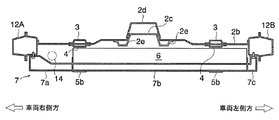
FIG. 1 illustrates a
ボデー10の前方側には、車長方向(車両前後方向)に延びる左右一対のメインフレーム1A,1Bが配置される。同様に、ボデー10の後方側にも、車長方向に延びる左右一対のリアサイドメンバ11A,11Bが設けられる。これらのメインフレーム1A,1B及びリアサイドメンバ11A,11Bはモノコックボデーのサブフレームとして形成されており、それぞれ車幅方向に離間して配置される。
On the front side of the
左右のリアサイドメンバ11A,11B間には、車幅方向に延びる第一リアフロアクロスメンバ15及び第二リアフロアクロスメンバ16が架け渡される。第一リアフロアクロスメンバ15は、左右のリアサイドメンバ11A,11Bの前端同士を接続する部材である。また、第二リアフロアクロスメンバ16は、第一リアフロアクロスメンバ15よりも後方において左右のリアサイドメンバ11A,11B間を接続する。
A first rear
ボデー10の側辺には、車長方向に延びる左右一対のサイドシル12A,12Bが設けられる。サイドシル12A,12Bは、ドアの下部の敷居をなすフレームであり、その後端部はリアサイドメンバ11A,11Bに接続される。
ここでは、メインフレーム1A,1B、リアサイドメンバ11A,11B、サイドシル12A,12Bのそれぞれが、車両の中心に対して左右対称に配置されている。以下、左右の区別が必要な場合を除き、単にメインフレーム1,リアサイドメンバ11,サイドシル12と称する。
A pair of left and right side sills 12 </ b> A and 12 </ b> B extending in the vehicle length direction is provided on the side of the
Here, the
この車両のバッテリユニット9は、上述のメインフレーム1,リアサイドメンバ11及びサイドシル12に対して、ボデー10の下面側から固定される。以下、バッテリユニット9の取付構造について詳述する。
The battery unit 9 of the vehicle is fixed from the lower surface side of the
[2.詳細構成]
[2−1.メインフレーム]
図2(a)に示すように、メインフレーム1は車長方向前方から順に、前方部1a,中間部1b,後方部1cを有する。前方部1aは車室よりも前方に位置する部位であり、車長方向にほぼ水平に延びている。また、中間部1bは前方部1aの後端から下方へ向けて屈曲された部位であり、後方部1cは中間部1bの後端からほぼ水平に延びた部位である。中間部1b及び後方部1cは、側面視において車室の前方における乗員の足下の空間を形成すべく、下方へ落ち込むように配置される。メインフレーム1の断面形状(車長方向に垂直な平面での切断面形状)は閉断面である。
[2. Detailed configuration]
[2-1. main frame]
As shown in FIG. 2A, the
[2−2.フロアパネル]
図2(a)及び図3に示すように、メインフレーム1の後端にはフロアパネル2が固定される。フロアパネル2は、車室の床面をなす板状の部材であり、フロア屈曲面2aとフロア水平面2bとを有する。
フロア屈曲面2aは、左右のメインフレーム1における後方部1cの上面に固定された部位であり、その後方側を上方へ向けて屈曲形成された面である。一方、フロア水平面2bは、フロア屈曲面2aの後端からさらに後方側へとほぼ水平に延びる面である。つまり、メインフレーム1の後端を基準として、フロアパネル2の後端側を上方へ向けて屈曲させることで、乗員の足下の空間を確保しつつ着座シートの基端部における床面を上昇させ、フロアパネル2よりも下方の空間を形成する。
[2-2. Floor panel]
As shown in FIGS. 2A and 3, the
The
フロア水平面2bには、強度確保のための屈曲形状や凹凸形状が形成される。本実施形態では、図4に示すように、フロア水平面2bの車幅方向中央部において車長方向に延びるトンネル状の凸部2cが形成されている。また、凸部2cを構成する屈曲辺の補強部材として、バックボーンリンフォース2d及び一対のバックボーンサイドメンバ2eが固設されている。これらの補強部材は、凸部2cに沿って車長方向に配置される。バックボーンリンフォース2dは凸部2cの上面側に固定され、バックボーンサイドメンバ2eは凸部2cの下面側に固定される。
The floor
また、図3に示すように、フロア水平面2bの上面側の補強部材として、車幅方向に延びるように配置された一対のフロアクロスメンバ8が設けられる。一対のフロアクロスメンバ8のうち、前方側のものを第一フロアクロスメンバ8aと呼び、後方側のものを第二フロアクロスメンバ8bと呼ぶ。第一フロアクロスメンバ8a及び第二フロアクロスメンバ8bは平行に配置される。これらの第一フロアクロスメンバ8a及び第二フロアクロスメンバ8bは、ともに下方へ向けて開放されたハット型チャンネル形状の断面を有し、フロアパネル2との間に閉断面構造を形成する。
Further, as shown in FIG. 3, a pair of floor cross members 8 arranged to extend in the vehicle width direction are provided as reinforcing members on the upper surface side of the floor
[2−3.フロアアッパメンバ]
図3に示すように、メインフレーム1とフロアパネル2との間には、フロアパネル2を挟んでその上面及び下面を補強する部材として、フロアアッパメンバ3及びフロアロアメンバ4が設けられる。
フロアアッパメンバ3は、メインフレーム1の中間部1bからフロア屈曲面2aに沿って上方へ屈曲するとともにフロア水平面2bに沿って車両後方へ延びた部材であり、メインフレーム1の後方部1cの上面及びフロア水平面2bの上面に固定される。つまり、フロアアッパメンバ3はフロアパネル2よりも上方に配置され、車室側に突出して設けられる。
[2-3. Floor upper member]
As shown in FIG. 3, a floor
The floor
また、フロアアッパメンバ3の後端は、第二フロアクロスメンバ8bにも接続される。これにより、メインフレーム1側からフロアアッパメンバ3に荷重が伝達された場合には、その荷重が第二フロアクロスメンバ8bを介してフロアパネル2の全体に拡散される。
フロアアッパメンバ3の断面形状は、図4に示すように、下方へ向けて開放されたハット型チャンネル形状である。フロアアッパメンバ3の開放された一面はフロアパネル2の上面によって閉塞されるため、フロアアッパメンバ3とフロアパネル2との間には車長方向へ延びる閉断面構造が形成される。フロアアッパメンバ3は、フロアパネル2の上面を補強し、特にフロア屈曲面2aの上面側を補強するように機能する。
The rear end of the floor
As shown in FIG. 4, the cross-sectional shape of the floor
[2−4.フロアロアメンバ]
フロアロアメンバ4は、メインフレーム1の後端からフロア屈曲面2aに沿って上方へ屈曲するとともにフロア水平面2bに沿って車両後方へ延びた部材であり、メインフレーム1の後方部1cの下面及びフロア水平面2bの下面に固定される。つまり、フロアロアメンバ4はフロアパネル2よりも下方に配置され、車室外に設けられる。以下、メインフレーム1の後方部1cの下面に対して固定されるフロアメンバ4の部位を、固定部4aと呼ぶ。
[2-4. Floor lower member]
The floor
また、フロアロアメンバ4の後端は、第一フロアクロスメンバ8aにも接続される。これにより、メインフレーム1側からフロアロアメンバ4に荷重が伝達された場合には、その荷重が第一フロアクロスメンバ8aを介してフロアパネル2の全体に拡散される。
フロアロアメンバ4の断面形状は、図4に示すように、上方へ向けて開放されたハット型チャンネル形状である。フロアロアメンバ4の開放された一面はフロアパネル2の下面によって閉塞されるため、フロアロアメンバ4とフロアパネル2との間には車長方向へ延びる閉断面構造が形成される。フロアロアメンバ4は、フロアパネル2の下面を補強し、特にフロア屈曲面2aの下面側を補強するように機能する。
The rear end of the floor
The cross-sectional shape of the floor
上記のフロアアッパメンバ3及びフロアロアメンバ4は、図2(b)に示すように、上面視においてメインフレーム1とほぼ同一の幅で、メインフレーム1をそのまま車長方向後方へと延長したように配置される。フロアアッパメンバ3及びフロアロアメンバ4は一体の強度部材として機能し、すなわちメインフレーム1から伝達される荷重を受ける強度部材としても機能する。なお、メインフレーム1の後方の強度部材に所定の高さ方向の寸法が要求される場合、フロアアッパメンバ3の高さ方向の寸法を大きくするほど、フロアロアメンバ4の高さ方向の寸法が小さくなり、フロアパネル2よりも下方の空間がより大きくなる。
As shown in FIG. 2 (b), the floor
[2−5.他のサブフレーム等]
図3に示すように、フロアパネル2におけるフロア水平面2bの後端部は第一リアフロアクロスメンバ15に接合され、これによりリアサイドメンバ11に対して固定される。また、第一リアフロアクロスメンバ15及び第二リアフロアクロスメンバ16の上面には、これらの部材間を覆うようにリアフロアパネル17が取り付けられる。リアフロアパネル17の下方には、図2(a),(b)及び図3中に二点鎖線で示すように、燃料タンク13が配置される。燃料タンク13の下面は、第二リアフロアクロスメンバ16に固定されたブラケット19と第一リアフロアクロスメンバ15の下面とに支持されたカバー20で覆われる。
[2-5. Other subframes]
As shown in FIG. 3, the rear end portion of the floor
燃料タンク13は、図2(b)に示すように、上面視において第一リアフロアクロスメンバ15,第二リアフロアクロスメンバ16及び左右のリアサイドメンバ11によって囲まれた空間内に配置される。燃料タンク13内に貯留される燃料は、この車両の内燃機関の駆動に供される。
第一リアフロアクロスメンバ15とリアサイドメンバ11との接合部近傍には、ブレース18が介装される。ブレース18は、後述するバッテリユニットをボデー10に取り付けるための斜材である。また、図2中に一点鎖線で示すように、右側のサイドシル12Aよりもボデー10の内側に、車長方向に沿って排気装置14が配置される。排気装置14はこの車両の内燃機関の排ガスを車外へ排出する。
As shown in FIG. 2B, the
A
[3.バッテリユニット]
図1に示すように、バッテリユニット9(車両用バッテリユニット)は、上述のメインフレーム1,リアサイドメンバ11及びサイドシル12に対して、ボデー10の下面側から固定される。バッテリユニット9は、二本の縦方向バッテリフレーム5A,5Bと、二本の横方向バッテリフレーム7A,7Bと、バッテリケース6とを備えて構成される。二本の縦方向バッテリフレーム5A,5Bは平行であり、また、二本の横方向バッテリフレーム7A,7Bも平行である。
[3. Battery unit]
As shown in FIG. 1, the battery unit 9 (vehicle battery unit) is fixed to the
ここでは、二本の縦方向バッテリフレーム5A,5Bが同一の構造を有し、左右対称の形状であるものとする。また、二本の横方向バッテリフレーム7A,7Bも同一の構造を有するものとする。以下、左右の区別が必要な場合を除き、単に縦方向バッテリフレーム5,横方向バッテリフレーム7とも称する。縦方向バッテリフレーム5及び横方向バッテリフレーム7は、井桁に組まれて互いに剛に接合され、四ヶ所の接合部を介して互いに荷重を伝達する。
Here, it is assumed that the two
[3−1.縦方向バッテリフレーム]
縦方向バッテリフレーム5(第一バッテリフレーム)は車長方向に延びた一対の強度部材であり、車幅方向に間隔をあけて配置される。また、図2(b)に示すように、縦方向バッテリフレーム5は上面視においてメインフレーム1に重なる位置(すなわち、フロアアッパメンバ3及びフロアロアメンバ4に重なる位置)に配置される。
[3-1. Vertical battery frame]
The vertical battery frame 5 (first battery frame) is a pair of strength members extending in the vehicle length direction, and is arranged at intervals in the vehicle width direction. As shown in FIG. 2B, the
図3に示すように、縦方向バッテリフレーム5は、前端部5a,中央部5b及び後端部5cを有する。前端部5a及び後端部5cはそれぞれ、メインフレーム1及びブレース18に対する締結固定がなされる部位であり、中央部5bはその上部にバッテリケース6を支持する部位である。これらの各部5a〜5cはともに閉断面構造を有し、部材の幅方向(車幅方向)の寸法は同一である。
As shown in FIG. 3, the
縦方向バッテリフレーム5は、バッテリケース6の前端から後端に渡って一体に設けられるとともに、さらにバッテリケース6よりも前方及び下方へ突出するように設けられる。本実施形態では、前端部5a及び後端部5cの高さ方向の寸法が中央部5bの高さ方向の寸法よりも大きく形成されている。
前端部5aは、メインフレーム1の後端とフロアロアメンバ4との固定部4aに対して、ボデー10の下面側から締結固定される。図3に示すように、メインフレーム1の後方部1cにおける後端とフロアロアメンバ4との固定部4aよりも後方において、フロア屈曲面2a及びフロアロアメンバ4が上方へ屈曲している。したがって、前端部5aはメインフレーム1,フロアアッパメンバ3及びフロアロアメンバ4からなる強度部材の屈曲点に締結固定されることになる。
The
The
また、後端部5cは、ボデー10の下面側からブレース18に対して締結固定される。つまり、縦方向バッテリフレーム5はボデー10に対して着脱自在に固定される。
Further, the
[3−2.横方向バッテリフレーム]
横方向バッテリフレーム7(第二バッテリフレーム)は車幅方向に延びた一対の強度部材であり、車長方向に間隔をあけて配置される。図3に示すように、横方向バッテリフレーム7はフロアクロスメンバ8a,8bの位置に合わせてそれぞれの下方に配置される。後方の横方向バッテリフレーム7Bは、第二フロアクロスメンバ8bの直下方に設けられ、前方の横方向バッテリフレーム7Aは、第一フロアクロスメンバ8aの直下方に設けられる。
[3-2. Horizontal battery frame]
The lateral battery frame 7 (second battery frame) is a pair of strength members extending in the vehicle width direction, and is arranged at intervals in the vehicle length direction. As shown in FIG. 3, the
本実施形態では、後方の横方向バッテリフレーム7Bが、側面視においてボデー10のセンターピラーの基端部と重なる部位に配置され、前方の横方向バッテリフレーム7Aが、フロントピラーの基端部とセンターピラーの基端部との中間位置の近傍に配置されている。
図4に示すように、横方向バッテリフレーム7は、右端部7a,第二中央部7b及び左端部7cを有する。右端部7a及び左端部7cはそれぞれ、サイドシル12A,12Bに対する締結固定がなされる部位であり、第二中央部7bはその上部にバッテリケース6を支持する部位である。つまり、横方向バッテリフレーム7は、縦方向バッテリフレーム5と同様に、ボデー10に対して着脱自在に固定される。これらの各部7a〜7cはともに閉断面構造を有し、部材の幅方向(車長方向)の寸法及び高さ方向の寸法が同一である。
In the present embodiment, the rear
As shown in FIG. 4, the
横方向バッテリフレーム7は、縦方向バッテリフレーム5と同様に、バッテリケース6の左端から右端に渡って一体に設けられるとともに、さらにバッテリケース6よりも左方及び右方へ突出するように設けられる。
Similarly to the
[3−3.バッテリケース]
バッテリケース6は、縦方向バッテリフレーム5A,5B及び横方向バッテリフレーム7A,7Bを井桁に組んだフレームの上に支持される。バッテリケース6の内部は気密性及び絶縁性が保たれ、図示しない複数のバッテリパックが内装される。図3,図4に示すように、バッテリユニット9をボデー10へ取り付けた状態において、バッテリケース6とフロアパネル2及びフロアロアメンバ4との間には、所定のクリアランスが設けられる。
[3-3. Battery case]
The
[4.作用,効果]
図3中に黒矢印で示すように、メインフレーム1を介して車両前方からの荷重が作用した場合、その荷重はメインフレーム1の後方に接続されたフロアアッパメンバ3及びフロアロアメンバ4へ伝達される。一方、フロアアッパメンバ3及びフロアロアメンバ4の上方への屈曲点に締結固定された縦方向バッテリフレーム5にも荷重が伝達される。したがって、図3中に白矢印で示すように、荷重が上下方向に分散される。
[4. Action, effect]
As shown by black arrows in FIG. 3, when a load from the front of the vehicle acts via the
フロアアッパメンバ3及びフロアロアメンバ4側へ伝達された荷重はさらに、第一フロアクロスメンバ8a及び第二フロアクロスメンバ8bを介してフロアパネル2へと拡散されるとともに、サイドシル12へと拡散される。また、縦方向バッテリフレーム5側へ伝達された荷重は横方向バッテリフレーム7を介してサイドシル12へと拡散されるとともに、ブレース18を介して第一リアフロアクロスメンバ15とリアサイドメンバ11へと拡散される。
The load transmitted to the floor
このように、本取付構造によれば、メインフレーム1から入力される荷重を、フロアアッパメンバ3及びフロアロアメンバ4側と、縦方向バッテリフレーム5側との二方向へと分散させることができ、さらにボデー10全体へとその荷重を分散させることができる。これにより、縦方向バッテリフレーム5とフロアロアメンバ4との間に配置されるバッテリケース6を効果的に保護することができる。
Thus, according to the present mounting structure, the load input from the
また、バッテリケース6に与えられる荷重が減少するため、剛性や強度を予め高めておく必要がなくなり、軽量化が容易になるというメリットがある。さらに、荷重を分散させることにより車室の変形をも抑制することができ、車室空間をより効果的に保持することができる。
特に、縦方向バッテリフレーム5がバッテリケース6の配置空間を縦断するように、メインフレーム1からリアサイドメンバ11側まで延ばされて固定されるため、縦方向バッテリフレーム5からバッテリケース6へ伝達されうる荷重を減少させることができ、かつ、荷重をボデー10全体へと逃がすことができる。
Further, since the load applied to the
In particular, since the
さらに、横方向バッテリフレーム7についても同様であり、バッテリケース6の配置空間を横断するように、サイドシル12まで延ばされて固定されるため、横方向バッテリフレーム7からバッテリケース6へ伝達されうる荷重を減少させることができ、かつ、荷重をボデー10全体へと逃がすことができる。
加えて、車両の上面視におけるフロアロアメンバ4及びフロアアッパメンバ3の後端の位置が、それぞれ第一フロアクロスメンバ8a及び第二フロアクロスメンバ8bの位置に一致するため、メインフレーム1から入力される荷重の伝達経路を確保することができ、荷重の分散性をさらに高めることができる。
Further, the same applies to the
In addition, the positions of the rear ends of the floor
また、後方側を上方へ向けて屈曲形成されたフロア屈曲面2aをフロアパネル2に設けるとともに、フロアアッパメンバ3及びフロアロアメンバ4を設けてフロア屈曲面2aの上面側及び下面側を補強することで、フロアアッパメンバ3及びフロアロアメンバ4からなる強度部材の下方に空間を設けることができる。つまり、左右のメインフレーム1の間隔とは無関係にバッテリユニット9の幅寸法を設定することが可能となり、バッテリユニット9の寸法制限が緩和される。
Further, the
したがって、バッテリユニット9の高さ方向の寸法や車長方向の寸法を増大させることなくその体積を増大させることができる。また、バッテリユニット9の配設位置が左右のメインフレーム1の位置に拘束されないため、例えば図1に示すように、サイドシル12とバッテリユニット9との間に排気装置14を設けるといった自由度の高いレイアウトが可能となる。
Therefore, the volume of the battery unit 9 can be increased without increasing the dimension in the height direction and the dimension in the vehicle length direction. Further, since the arrangement position of the battery unit 9 is not restricted by the positions of the left and right
また、フロアパネル2の上面側に固定されるフロアアッパメンバ3と下面側に固定されるフロアロアメンバ4とを上面視で重なる位置に配設することで、これらを一体の強度部材とみなすことができる。これにより、フロアアッパメンバ3の高さ方向の寸法を大きくするほど、フロアロアメンバ4の高さ方向の寸法を小さくすることができ、フロアパネル2よりも下方の空間、すなわちバッテリユニット9を配置するための空間を増大させることができる。したがって、バッテリユニット9の体積をさらに増大させることができる。
Further, the floor
特に、上述の実施形態のようなハイブリッド車両において、リアフロアパネル17の下方に燃料タンク13を設置するレイアウトの場合には、燃料タンク13の容量を確保した上でバッテリユニット9を拡大することができる。
また、縦方向バッテリフレーム5及び横方向バッテリフレーム7がボデー10に対して着脱自在に固定されるため、これらの縦方向バッテリフレーム5及び横方向バッテリフレーム7とバッテリケース6とを含む全てをバッテリユニット9として形成することができる。つまり、ボデー10の強度部材としての機能を有する縦方向バッテリフレーム5に対して、バッテリケース6の補強部材としての機能を付与することができる。これにより、バッテリケース6の剛性,強度を向上させることができるほか、バッテリユニット9の取り外し時における形態保持性が高まり、メンテナンス性を向上させることができる。
In particular, in the hybrid vehicle as in the above-described embodiment, in the case of a layout in which the
Further, since the
また、縦方向バッテリフレーム5と横方向バッテリフレーム7とが交差した状態で固定されるため、バッテリユニット9の剛性,強度を向上させることができる。さらに、縦方向バッテリフレーム5及び横方向バッテリフレーム7がそれぞれ一対設けられるため、井桁形状に組むことができ、バッテリユニット9の剛性,強度をさらに向上させることができる。
Further, since the
また、車両の上面視における横方向バッテリフレーム7の位置とフロアクロスメンバ8の位置とを一致させることにより、車幅方向からの荷重に対する剛性,強度をさらに向上させることができる。
Further, by matching the position of the
[5.変形例等]
上述した実施形態の一例に関わらず、本実施形態の趣旨を逸脱しない範囲で種々変形して実施することができる。本実施形態の各構成は、必要に応じて取捨選択することができ、あるいは適宜組み合わせてもよい。
[5. Modified example]
Regardless of the example of the embodiment described above, various modifications can be made without departing from the spirit of the present embodiment. Each structure of this embodiment can be selected as needed, or may be combined appropriately.
上述の実施形態では、前端部5a及び後端部5cの高さ方向の寸法が中央部5bの高さ方向の寸法よりも大きく形成された縦方向バッテリフレーム5を例示したが、例えば角柱状の部材を用いて縦方向バッテリフレーム5がほぼ均一な断面形状を持つように構成してもよい。また、横方向バッテリフレーム7についても同様であり、部材に要求される剛性や強度に応じて、右端部7a,第二中央部7b及び左端部7cの断面形状を相違させてもよい。
In the above-described embodiment, the
また、上述の実施形態のバッテリユニット9では、横方向バッテリフレーム7の断面形状が車幅方向の何れの位置においても同一であって、すなわち断面が車幅方向に通されているが、このような構成の代わりに縦方向バッテリフレーム5の断面を車長方向に通す構成としてもよい。縦方向バッテリフレーム5及び横方向バッテリフレーム7のどちらの断面を通すかは任意であり、車両形態や仕向先に応じて選択してもよい。
In the battery unit 9 of the above-described embodiment, the cross-sectional shape of the
また、上述の実施形態では、メインフレーム1,縦方向バッテリフレーム5及び横方向バッテリフレーム7の断面形状が閉断面であるものを例示したが、各強度部材の具体的な形状についてはこれに限定されない。なお、フロアアッパメンバ3及びフロアロアメンバ4についても同様である。
また、上述の実施形態は、ハイブリッド車両における車両用バッテリユニットの取付構造を例示したが、本発明の適用対象はこれに限られることはなく、例えば電気自動車や燃料電池自動車,ハイブリッド車両,プラグインハイブリッド車両等のバッテリユニット9を搭載する車両全般に適用することができる。
Moreover, in the above-described embodiment, the
Moreover, although the above-mentioned embodiment illustrated the attachment structure of the battery unit for vehicles in a hybrid vehicle, the application object of this invention is not restricted to this, For example, an electric vehicle, a fuel cell vehicle, a hybrid vehicle, a plug-in The present invention can be applied to all vehicles equipped with a battery unit 9 such as a hybrid vehicle.
1,1A,1B メインフレーム
1a 前方部
1b 中間部
1c 後方部
2 フロアパネル
2a フロア屈曲面
2b フロア水平面
2c 凸部
2d バックボーンリンフォース
2e バックボーンサイドメンバ
3 フロアアッパメンバ
4 フロアロアメンバ
4a 固定部
5,5A,5B 縦方向バッテリフレーム(第一バッテリフレーム)
5a 前端部
5b 中央部
5c 後端部
6 バッテリケース
7,7A,7B 横方向バッテリフレーム(第二バッテリフレーム)
7a 右端部
7b 第二中央部
7c 左端部
8 フロアクロスメンバ
8a 第一フロアクロスメンバ
8b 第二フロアクロスメンバ
9 バッテリユニット(車両用バッテリユニット)
10 ボデー
11,11A,11B リアサイドメンバ
12,12A,12B サイドシル
13 燃料タンク
14 排気装置
15 第一リアフロアクロスメンバ
16 第二リアフロアクロスメンバ
17 リアフロアパネル
18 ブレース
19 ブラケット
20 カバー
1, 1A,
5a
7a
10
Claims (7)
一対の該メインフレームに固定されて車室床面をなし、後方側を上方へ向けて屈曲形成されたフロア屈曲面と該フロア屈曲面の後端からほぼ水平に延びるフロア水平面とを有するフロアパネルと、
該メインフレームの後端から該フロア屈曲面に沿って該車両の後方へ延び、該メインフレームの上面及び該フロア水平面の上面に固定されたフロアアッパメンバと、
該メインフレームの後端から該フロア屈曲面に沿って該車両の後方へ延び、該メインフレームの下面及び該フロア水平面の下面に固定されたフロアロアメンバと、
該メインフレームの後端と該フロアロアメンバとの固定部に対して取り付けられ、該固定部から該車両の後方へ延びた一対の第一バッテリフレームと、
該一対の第一バッテリフレームの上に支持され、該一対の第一バッテリフレームと該フロアロアメンバとの間に配置されたバッテリケースと
を備えたことを特徴とする、車両用バッテリユニットの取付構造。 A main frame that extends in the longitudinal direction of the vehicle and is provided with a pair of left and right;
A floor panel fixed to the pair of main frames to form a passenger compartment floor surface, and having a floor bent surface formed by bending the rear side upward and a floor horizontal surface extending substantially horizontally from the rear end of the floor bent surface. When,
A floor upper member extending from the rear end of the main frame to the rear of the vehicle along the floor bending surface, and fixed to the upper surface of the main frame and the upper surface of the floor horizontal surface;
A floor lower member extending from the rear end of the main frame to the rear of the vehicle along the floor bending surface, and fixed to the lower surface of the main frame and the lower surface of the floor horizontal surface;
A pair of first battery frames attached to a fixed portion between the rear end of the main frame and the floor lower member and extending from the fixed portion to the rear of the vehicle;
An attachment of a battery unit for a vehicle, comprising: a battery case supported on the pair of first battery frames and disposed between the pair of first battery frames and the floor lower member. Construction.
ことを特徴とする、請求項1記載の車両用バッテリユニットの取付構造。 The mounting structure for a vehicle battery unit according to claim 1, wherein the first battery frame is detachably fixed to the fixing portion.
ことを特徴とする、請求項1又は2記載の車両用バッテリユニットの取付構造。 3. The first battery frame is provided from at least a front end to a rear end of the battery case, and a rear end portion thereof is fixed to a rear side member of the vehicle. Mounting structure for a vehicle battery unit.
ことを特徴とする、請求項1〜3記載の車両用バッテリユニットの取付構造。 The mounting structure for a vehicle battery unit according to claim 1, further comprising a second battery frame that extends in a vehicle width direction of the vehicle and is fixed to the first battery frame.
ことを特徴とする、請求項4記載の車両用バッテリユニットの取付構造。 The vehicle-use vehicle according to claim 4, wherein the second battery frame is provided at least from the left end to the right end of the battery case, and both left and right ends thereof are fixed to a side sill of the vehicle. Battery unit mounting structure.
一対の該第二バッテリフレームの上方における該フロアパネルの上面に固定され、車幅方向に延びる一対のフロアクロスメンバをさらに備えた
ことを特徴とする、請求項5記載の車両用バッテリユニットの取付構造。 A pair of the second battery frames are provided at intervals in the front-rear direction of the vehicle,
The vehicle battery unit attachment according to claim 5, further comprising a pair of floor cross members fixed to the upper surface of the floor panel above the pair of second battery frames and extending in the vehicle width direction. Construction.
該フロアアッパメンバが、該フロア水平面の上面において、該一対のフロアクロスメンバのうち後方のフロアクロスメンバと一体に固定される
ことを特徴とする、請求項6記載の車両用バッテリユニットの取付構造。
The floor lower member is fixed below the front floor cross member of the pair of floor cross members on the lower surface of the floor horizontal plane,
The vehicle battery unit mounting structure according to claim 6, wherein the floor upper member is fixed integrally with a rear floor cross member of the pair of floor cross members on an upper surface of the floor horizontal plane. .
Priority Applications (1)
| Application Number | Priority Date | Filing Date | Title |
|---|---|---|---|
| JP2009281213A JP5256183B2 (en) | 2009-12-11 | 2009-12-11 | Mounting structure for vehicle battery unit |
Applications Claiming Priority (1)
| Application Number | Priority Date | Filing Date | Title |
|---|---|---|---|
| JP2009281213A JP5256183B2 (en) | 2009-12-11 | 2009-12-11 | Mounting structure for vehicle battery unit |
Related Child Applications (1)
| Application Number | Title | Priority Date | Filing Date |
|---|---|---|---|
| JP2013083738A Division JP2013154880A (en) | 2013-04-12 | 2013-04-12 | Mounting structure of vehicle battery unit |
Publications (2)
| Publication Number | Publication Date |
|---|---|
| JP2011121483A JP2011121483A (en) | 2011-06-23 |
| JP5256183B2 true JP5256183B2 (en) | 2013-08-07 |
Family
ID=44285826
Family Applications (1)
| Application Number | Title | Priority Date | Filing Date |
|---|---|---|---|
| JP2009281213A Active JP5256183B2 (en) | 2009-12-11 | 2009-12-11 | Mounting structure for vehicle battery unit |
Country Status (1)
| Country | Link |
|---|---|
| JP (1) | JP5256183B2 (en) |
Cited By (1)
| Publication number | Priority date | Publication date | Assignee | Title |
|---|---|---|---|---|
| KR20220023190A (en) * | 2020-08-20 | 2022-03-02 | 현대자동차주식회사 | Structure for mounting battery on body |
Families Citing this family (15)
| Publication number | Priority date | Publication date | Assignee | Title |
|---|---|---|---|---|
| US9174683B2 (en) | 2011-10-11 | 2015-11-03 | Suzuki Motor Corporation | Floor reinforcement structure for vehicle body |
| JP5906689B2 (en) | 2011-11-22 | 2016-04-20 | トヨタ自動車株式会社 | Vehicle battery mounting structure |
| CN103998273B (en) | 2011-12-15 | 2017-05-17 | 本田技研工业株式会社 | Vehicle body structure |
| JP5854149B2 (en) * | 2012-09-04 | 2016-02-09 | 日産自動車株式会社 | Electric vehicle body structure |
| JP2013154880A (en) * | 2013-04-12 | 2013-08-15 | Mitsubishi Motors Corp | Mounting structure of vehicle battery unit |
| JP6687880B2 (en) * | 2015-11-11 | 2020-04-28 | 三菱自動車エンジニアリング株式会社 | Evaporative fuel processor |
| JP6555244B2 (en) | 2016-12-19 | 2019-08-07 | トヨタ自動車株式会社 | vehicle |
| KR102440612B1 (en) * | 2017-12-15 | 2022-09-05 | 현대자동차 주식회사 | Side vehicle body reinforcing structure |
| JP6988590B2 (en) | 2018-03-09 | 2022-01-05 | トヨタ自動車株式会社 | Vehicle rear structure |
| JP6757362B2 (en) | 2018-05-25 | 2020-09-16 | 本田技研工業株式会社 | Body undercarriage |
| US11027782B2 (en) * | 2018-07-03 | 2021-06-08 | Toyota Jidosha Kabushiki Kaisha | Vehicle front-part structure |
| CN112638681B (en) | 2018-08-28 | 2023-09-19 | 本田技研工业株式会社 | Configuration structure of storage battery pack |
| CN111204204A (en) | 2018-11-01 | 2020-05-29 | 宁德时代新能源科技股份有限公司 | Lower box and battery box |
| JP7248609B2 (en) * | 2020-02-05 | 2023-03-29 | トヨタ自動車株式会社 | vehicle structure |
| CN115230827A (en) * | 2022-08-17 | 2022-10-25 | 上海汽车集团股份有限公司 | Lower vehicle body framework and vehicle |
Family Cites Families (4)
| Publication number | Priority date | Publication date | Assignee | Title |
|---|---|---|---|---|
| JP3321066B2 (en) * | 1997-12-29 | 2002-09-03 | ダイハツ工業株式会社 | Reinforcement structure of lower part of car body |
| JP3995315B2 (en) * | 1997-09-16 | 2007-10-24 | 富士重工業株式会社 | Front body structure of the vehicle |
| JP2006290294A (en) * | 2005-04-14 | 2006-10-26 | Toyota Motor Corp | Vehicular floor structure |
| JP5061941B2 (en) * | 2008-02-18 | 2012-10-31 | 日産自動車株式会社 | Vehicle battery mounting structure |
-
2009
- 2009-12-11 JP JP2009281213A patent/JP5256183B2/en active Active
Cited By (2)
| Publication number | Priority date | Publication date | Assignee | Title |
|---|---|---|---|---|
| KR20220023190A (en) * | 2020-08-20 | 2022-03-02 | 현대자동차주식회사 | Structure for mounting battery on body |
| KR102410520B1 (en) | 2020-08-20 | 2022-06-20 | 현대자동차주식회사 | Structure for mounting battery on body |
Also Published As
| Publication number | Publication date |
|---|---|
| JP2011121483A (en) | 2011-06-23 |
Similar Documents
| Publication | Publication Date | Title |
|---|---|---|
| JP5256183B2 (en) | Mounting structure for vehicle battery unit | |
| JP2013154880A (en) | Mounting structure of vehicle battery unit | |
| CN111661171B (en) | Lower body structure of vehicle | |
| US9956994B2 (en) | Lower vehicle-body structure of automotive vehicle | |
| JP5558588B2 (en) | Auto body structure | |
| JP5966824B2 (en) | Track-type electric vehicle frame structure | |
| JP5187820B2 (en) | Upper body structure for fuel cell vehicles for reinforcing floor kick-up | |
| US8393426B2 (en) | Vehicle structure of a hybrid vehicle | |
| CN110588312B (en) | Vehicle body lower structure | |
| US8118125B2 (en) | Vehicle body floor structure | |
| US8813888B2 (en) | Vehicle body rear structure | |
| JP6434888B2 (en) | Body structure | |
| JP2009193942A (en) | Battery-mounting structure for vehicle | |
| JP5729207B2 (en) | Vehicle power supply support structure | |
| JP2020026159A (en) | Vehicle lower part structure | |
| JP6137105B2 (en) | Battery drive battery mounting structure | |
| JP2018144700A (en) | Electric vehicle body structure | |
| JP2016107907A (en) | Electric power conversion system | |
| JP2015067122A (en) | Vehicle equipped with electric drive apparatus | |
| JP2019131006A (en) | Vehicle body rear part structure | |
| JP2018161934A (en) | Floor structure of vehicle body | |
| JP2021094925A (en) | Vehicle body rear part structure | |
| JP2008001147A (en) | Structure of mounting high-voltage electric equipment | |
| JP5848628B2 (en) | Car body rear structure | |
| JP2023051654A (en) | Vehicle body structure |
Legal Events
| Date | Code | Title | Description |
|---|---|---|---|
| A621 | Written request for application examination |
Free format text: JAPANESE INTERMEDIATE CODE: A621 Effective date: 20111121 |
|
| A977 | Report on retrieval |
Free format text: JAPANESE INTERMEDIATE CODE: A971007 Effective date: 20130325 |
|
| TRDD | Decision of grant or rejection written | ||
| A01 | Written decision to grant a patent or to grant a registration (utility model) |
Free format text: JAPANESE INTERMEDIATE CODE: A01 Effective date: 20130402 |
|
| A61 | First payment of annual fees (during grant procedure) |
Free format text: JAPANESE INTERMEDIATE CODE: A61 Effective date: 20130422 |
|
| R151 | Written notification of patent or utility model registration |
Ref document number: 5256183 Country of ref document: JP Free format text: JAPANESE INTERMEDIATE CODE: R151 |
|
| FPAY | Renewal fee payment (event date is renewal date of database) |
Free format text: PAYMENT UNTIL: 20160426 Year of fee payment: 3 |
|
| S531 | Written request for registration of change of domicile |
Free format text: JAPANESE INTERMEDIATE CODE: R313531 |
|
| R350 | Written notification of registration of transfer |
Free format text: JAPANESE INTERMEDIATE CODE: R350 |