JP5249149B2 - Stereoscopic image recording apparatus and method, stereoscopic image output apparatus and method, and stereoscopic image recording and output system - Google Patents
Stereoscopic image recording apparatus and method, stereoscopic image output apparatus and method, and stereoscopic image recording and output system Download PDFInfo
- Publication number
- JP5249149B2 JP5249149B2 JP2009169293A JP2009169293A JP5249149B2 JP 5249149 B2 JP5249149 B2 JP 5249149B2 JP 2009169293 A JP2009169293 A JP 2009169293A JP 2009169293 A JP2009169293 A JP 2009169293A JP 5249149 B2 JP5249149 B2 JP 5249149B2
- Authority
- JP
- Japan
- Prior art keywords
- display
- image
- images
- stereoscopic
- output
- Prior art date
- Legal status (The legal status is an assumption and is not a legal conclusion. Google has not performed a legal analysis and makes no representation as to the accuracy of the status listed.)
- Active
Links
Images


Classifications
-
- G—PHYSICS
- G06—COMPUTING; CALCULATING OR COUNTING
- G06T—IMAGE DATA PROCESSING OR GENERATION, IN GENERAL
- G06T7/00—Image analysis
- G06T7/0002—Inspection of images, e.g. flaw detection
-
- G—PHYSICS
- G06—COMPUTING; CALCULATING OR COUNTING
- G06T—IMAGE DATA PROCESSING OR GENERATION, IN GENERAL
- G06T7/00—Image analysis
- G06T7/97—Determining parameters from multiple pictures
-
- H—ELECTRICITY
- H04—ELECTRIC COMMUNICATION TECHNIQUE
- H04N—PICTORIAL COMMUNICATION, e.g. TELEVISION
- H04N13/00—Stereoscopic video systems; Multi-view video systems; Details thereof
- H04N13/10—Processing, recording or transmission of stereoscopic or multi-view image signals
- H04N13/106—Processing image signals
- H04N13/122—Improving the 3D impression of stereoscopic images by modifying image signal contents, e.g. by filtering or adding monoscopic depth cues
-
- H—ELECTRICITY
- H04—ELECTRIC COMMUNICATION TECHNIQUE
- H04N—PICTORIAL COMMUNICATION, e.g. TELEVISION
- H04N13/00—Stereoscopic video systems; Multi-view video systems; Details thereof
- H04N13/10—Processing, recording or transmission of stereoscopic or multi-view image signals
- H04N13/106—Processing image signals
- H04N13/144—Processing image signals for flicker reduction
-
- H—ELECTRICITY
- H04—ELECTRIC COMMUNICATION TECHNIQUE
- H04N—PICTORIAL COMMUNICATION, e.g. TELEVISION
- H04N13/00—Stereoscopic video systems; Multi-view video systems; Details thereof
- H04N13/10—Processing, recording or transmission of stereoscopic or multi-view image signals
- H04N13/106—Processing image signals
- H04N13/161—Encoding, multiplexing or demultiplexing different image signal components
-
- H—ELECTRICITY
- H04—ELECTRIC COMMUNICATION TECHNIQUE
- H04N—PICTORIAL COMMUNICATION, e.g. TELEVISION
- H04N13/00—Stereoscopic video systems; Multi-view video systems; Details thereof
- H04N13/10—Processing, recording or transmission of stereoscopic or multi-view image signals
- H04N13/106—Processing image signals
- H04N13/172—Processing image signals image signals comprising non-image signal components, e.g. headers or format information
- H04N13/178—Metadata, e.g. disparity information
-
- H—ELECTRICITY
- H04—ELECTRIC COMMUNICATION TECHNIQUE
- H04N—PICTORIAL COMMUNICATION, e.g. TELEVISION
- H04N13/00—Stereoscopic video systems; Multi-view video systems; Details thereof
- H04N13/10—Processing, recording or transmission of stereoscopic or multi-view image signals
- H04N13/189—Recording image signals; Reproducing recorded image signals
-
- H—ELECTRICITY
- H04—ELECTRIC COMMUNICATION TECHNIQUE
- H04N—PICTORIAL COMMUNICATION, e.g. TELEVISION
- H04N13/00—Stereoscopic video systems; Multi-view video systems; Details thereof
- H04N13/20—Image signal generators
- H04N13/204—Image signal generators using stereoscopic image cameras
- H04N13/239—Image signal generators using stereoscopic image cameras using two 2D image sensors having a relative position equal to or related to the interocular distance
-
- H—ELECTRICITY
- H04—ELECTRIC COMMUNICATION TECHNIQUE
- H04N—PICTORIAL COMMUNICATION, e.g. TELEVISION
- H04N5/00—Details of television systems
- H04N5/76—Television signal recording
- H04N5/765—Interface circuits between an apparatus for recording and another apparatus
- H04N5/775—Interface circuits between an apparatus for recording and another apparatus between a recording apparatus and a television receiver
- H04N5/7755—Interface circuits between an apparatus for recording and another apparatus between a recording apparatus and a television receiver the recorder being connected to, or coupled with, the antenna of the television receiver
-
- H—ELECTRICITY
- H04—ELECTRIC COMMUNICATION TECHNIQUE
- H04N—PICTORIAL COMMUNICATION, e.g. TELEVISION
- H04N5/00—Details of television systems
- H04N5/76—Television signal recording
- H04N5/907—Television signal recording using static stores, e.g. storage tubes or semiconductor memories
-
- H—ELECTRICITY
- H04—ELECTRIC COMMUNICATION TECHNIQUE
- H04N—PICTORIAL COMMUNICATION, e.g. TELEVISION
- H04N9/00—Details of colour television systems
- H04N9/79—Processing of colour television signals in connection with recording
- H04N9/80—Transformation of the television signal for recording, e.g. modulation, frequency changing; Inverse transformation for playback
- H04N9/804—Transformation of the television signal for recording, e.g. modulation, frequency changing; Inverse transformation for playback involving pulse code modulation of the colour picture signal components
- H04N9/8042—Transformation of the television signal for recording, e.g. modulation, frequency changing; Inverse transformation for playback involving pulse code modulation of the colour picture signal components involving data reduction
-
- G—PHYSICS
- G06—COMPUTING; CALCULATING OR COUNTING
- G06T—IMAGE DATA PROCESSING OR GENERATION, IN GENERAL
- G06T2207/00—Indexing scheme for image analysis or image enhancement
- G06T2207/10—Image acquisition modality
- G06T2207/10004—Still image; Photographic image
- G06T2207/10012—Stereo images
-
- G—PHYSICS
- G06—COMPUTING; CALCULATING OR COUNTING
- G06T—IMAGE DATA PROCESSING OR GENERATION, IN GENERAL
- G06T2207/00—Indexing scheme for image analysis or image enhancement
- G06T2207/30—Subject of image; Context of image processing
- G06T2207/30168—Image quality inspection
-
- H—ELECTRICITY
- H04—ELECTRIC COMMUNICATION TECHNIQUE
- H04N—PICTORIAL COMMUNICATION, e.g. TELEVISION
- H04N13/00—Stereoscopic video systems; Multi-view video systems; Details thereof
- H04N2013/0074—Stereoscopic image analysis
- H04N2013/0081—Depth or disparity estimation from stereoscopic image signals
Abstract
Description
本発明は、立体画像を作成するために異なる視点から撮影した複数の画像を取り扱う装置及び方法に関し、更に詳しくは、複数の画像を記録する立体画像記録装置及び方法と、複数の画像に基づいて立体画像を出力する立体画像出力装置及び方法と、複数画像の記録と立体画像の出力とを行う立体画像記録出力システムとに関する。 The present invention relates to an apparatus and method for handling a plurality of images taken from different viewpoints in order to create a stereoscopic image, and more specifically, based on a plurality of images and a stereoscopic image recording apparatus and method for recording a plurality of images. The present invention relates to a stereoscopic image output apparatus and method for outputting a stereoscopic image, and a stereoscopic image recording output system for recording a plurality of images and outputting a stereoscopic image.
2つの撮影部によって異なる視点から同時に被写体を撮影し、2つの画像を作成するデジタルカメラと、この2つの画像を用いて立体表示を行うデジタルフォトフレームと、2つの画像から製作される立体プリントとを備えた3Dデジタル映像システムが知られている(例えば、非特許文献1参照)。このシステムのデジタルカメラによって作成された2つの画像は、異なる視点から撮影することにより視差を生じている。デジタルフォトフレームは、2つの画像が観察者の左右の目によってそれぞれ別々に観察されるように表示する。これにより、観察者は、デジタルカメラにより撮影された画像を立体画像として観察することができる。 A digital camera that shoots a subject at the same time from two different viewpoints by two photographing units and creates two images, a digital photo frame that performs stereoscopic display using these two images, and a three-dimensional print produced from the two images There is known a 3D digital video system including the above (see, for example, Non-Patent Document 1). The two images created by the digital camera of this system produce parallax by shooting from different viewpoints. The digital photo frame displays two images so that they are observed separately by the left and right eyes of the observer. Thereby, the observer can observe the image image | photographed with the digital camera as a stereo image.
立体画像の観察は、通常の2次元画像の観察に比べて目が疲労しやすいことが知られている。これは、観察者の両目から画像までの距離である視距離と、観察者が左右の目で視差のある2つの画像をそれぞれ観察したときに2つの画像が1つに見える距離、すなわち左右の視線が輻輳する輻輳距離とが異なっていることが原因である。また、視距離と輻輳距離との差が大きいほど疲労度が大きくなることも分かっている。輻輳距離は、2つの画像間の視差によって変化する。 It is known that the observation of a stereoscopic image tends to cause eye fatigue compared to the observation of a normal two-dimensional image. This is because the viewing distance, which is the distance from the observer's eyes to the image, and the distance at which the two images appear as one when the observer observes two parallax images with the left and right eyes, that is, the left and right This is because the convergence distance at which the line of sight converges is different. It has also been found that the greater the difference between the viewing distance and the convergence distance, the greater the degree of fatigue. The convergence distance varies depending on the parallax between the two images.
立体画像が観察者に与える影響を軽減するため、立体画像の元となる2つの画像間の視差量を検出し、視差量に基づいて疲労度を評価し、疲労度評価量に基づいて立体画像を二次元画像に切り替える映像システムが発明されている(例えば、特許文献1参照)。 In order to reduce the effect of the stereoscopic image on the observer, the amount of parallax between the two images that are the source of the stereoscopic image is detected, the degree of fatigue is evaluated based on the amount of parallax, and the stereoscopic image is based on the amount of fatigue evaluation Has been invented (for example, see Patent Document 1).
特許文献1記載の発明は、視差量に基づいた疲労度評価量に基づいて立体画像を予告なく2次元画像に切り替えるので、観察者は、立体画像と二次元画像とを混在した状態で観察することになる。それにより、立体画像の観察を意図していた観察者に違和感を与えることが懸念される。また、立体画像と二次元画像とを混在して観察することにより、立体画像のみを観察している場合よりも目の疲労が大きくなることも考えられる。 In the invention described in Patent Document 1, since a stereoscopic image is switched to a two-dimensional image without notice based on the fatigue evaluation amount based on the amount of parallax, the observer observes the stereoscopic image and the two-dimensional image in a mixed state. It will be. As a result, there is a concern that a viewer who intends to observe a stereoscopic image may feel uncomfortable. It is also conceivable that eye fatigue becomes larger by observing a stereoscopic image and a two-dimensional image together than when observing only a stereoscopic image.
本発明の目的は、立体表示に適した複数画像のみを用いて立体画像を表示することにある。 An object of the present invention is to display a stereoscopic image using only a plurality of images suitable for stereoscopic display.
本発明の立体画像記録装置は、立体画像の表示用に同一シーンを異なる視点から撮影した複数の画像から互いに対応する対応点を抽出し、対応点間の視差量を測定し、視差量とその発生頻度の統計量を求める視差量測定手段と、統計量に基づいて、シーンの内容に応じて切り替えられる閾値以上の視差量の発生頻度の累計である頻度累計を算出し、頻度累計に基づいて複数の画像による立体表示の適性を判定し、この適性を表す少なくとも2段階以上の表示推奨レベルから判定結果に適合した表示推奨レベルを決定する立体表示適性判定手段と、複数の画像に表示推奨レベルを表す表示推奨情報を付加し、複数の画像を記憶する画像記憶手段とを備えている。 The stereoscopic image recording apparatus of the present invention extracts corresponding points corresponding to each other from a plurality of images obtained by capturing the same scene from different viewpoints for displaying a stereoscopic image , measures the amount of parallax between the corresponding points, A parallax amount measuring means for obtaining a statistic of the occurrence frequency, and based on the statistic, calculate a frequency total that is a cumulative frequency of occurrence of the parallax amount equal to or higher than a threshold that is switched according to the content of the scene. Three-dimensional display suitability determination means for determining the suitability of stereoscopic display using a plurality of images and determining a recommended display level that suits the determination result from at least two or more recommended display levels representing this suitability, and a recommended display level for a plurality of images Display recommendation information representing the image and an image storage means for storing a plurality of images.
また、立体表示適性判定手段は、算出した頻度累計と、頻度累計閾値とを比較して表示推奨レベルを決定している。表示推奨レベルは、頻度累計が頻度累計閾値よりも小さいほど高くなり、頻度累計が頻度累計閾値よりも大きいほど低くなることが好ましい。 In addition, the stereoscopic display aptitude determination unit determines the recommended display level by comparing the calculated frequency cumulative and the frequency cumulative threshold. The recommended display level is preferably higher as the frequency cumulative is smaller than the frequency cumulative threshold, and is preferably lower as the frequency cumulative is larger than the frequency cumulative threshold.
複数の画像による立体画像が、複数の画像フレームを順次に出力させる動画であるときには、視差量測定手段は、画像フレームごとに視差量の測定及び視差量の統計量を算出し、立体表示適性判定手段は、画像フレームごとに表示推奨レベルを決定することが好ましい。 When a stereoscopic image by a plurality of images is a moving image that sequentially outputs a plurality of image frames, the parallax amount measuring means calculates a parallax amount measurement and a parallax amount statistic for each image frame, and determines a stereoscopic display suitability. Preferably, the means determines a recommended display level for each image frame.
画像記憶手段は、複数の画像と表示推奨情報とを1つの画像ファイルとして記憶することが好ましい。 The image storage means preferably stores a plurality of images and display recommendation information as one image file.
また、本発明の立体画像記録方法は、立体画像の表示用に同一シーンを異なる視点から撮影した複数の画像から互いに対応する対応点を抽出し、対応点間の視差量を測定し、視差量とその発生頻度の統計量を求める視差量測定工程と、統計量に基づいて、シーンの内容に応じて切り替えられる閾値以上の視差量の発生頻度の累計である頻度累計を算出し、頻度累計に基づいて複数の画像による立体表示の適性を判定し、この適性を表す少なくとも2段階以上の表示推奨レベルから判定結果に適合した表示推奨レベルを決定する立体表示適性判定工程と、複数の画像に表示推奨レベルを表す表示推奨情報を付加し、複数の画像を記憶する記憶工程とを備えている。 Further, the stereoscopic image recording method of the present invention extracts corresponding points corresponding to each other from a plurality of images obtained by capturing the same scene from different viewpoints for displaying a stereoscopic image , measures the amount of parallax between the corresponding points, and calculates the amount of parallax. And a parallax amount measurement step for obtaining a statistic of the occurrence frequency, and based on the statistic, a frequency total that is a cumulative frequency of occurrence of a parallax amount greater than or equal to a threshold that is switched according to the content of the scene is calculated, and the frequency cumulative 3D display suitability determination step for determining the appropriateness of 3D display based on a plurality of images and determining a recommended display level suitable for the determination result from at least two or more recommended display levels representing the suitability, and displaying on the plurality of images A storage step of adding a display recommendation information indicating a recommended level and storing a plurality of images.
また、本発明の立体画像出力装置は、上述の立体画像記録装置により記録された複数の画像に付加されている表示推奨情報を読み取り、表示推奨情報から複数の画像による立体表示適性を判断し、立体表示適性に基づいて、複数の画像により立体画像を出力する出力手段の出力状態を切り換える出力制御手段を備えている。 In addition, the stereoscopic image output apparatus of the present invention reads display recommendation information added to a plurality of images recorded by the above-described stereoscopic image recording apparatus , determines the stereoscopic display suitability of the plurality of images from the display recommendation information, Output control means for switching the output state of the output means for outputting a stereoscopic image with a plurality of images based on the stereoscopic display suitability is provided.
出力制御手段は、表示推奨情報に基づいて、複数の画像による立体画像の出力を行うか否かを判定し、出力すると判定した立体画像を出力手段に出力させることが好ましい。また、出力制御手段は、表示推奨情報に基づいて、出力手段により出力される立体画像のサイズ又は再生時間を切り換えてもよい。また、出力制御手段は、出力手段により出力される立体画像が、複数の画像フレームを順次に出力させる動画であるときには、表示推奨情報に基づいて、画像フレームごとに出力するか否かを判定し、画像フレームを出力しないときには、その直前に出力した画像フレームの出力を継続させてもよい。 The output control means preferably determines whether or not to output a three-dimensional image with a plurality of images based on the recommended display information, and causes the output means to output the three-dimensional image determined to be output. The output control means may switch the size or playback time of the stereoscopic image output by the output means based on the display recommendation information. Further, when the stereoscopic image output by the output unit is a moving image that sequentially outputs a plurality of image frames, the output control unit determines whether to output each image frame based on the display recommendation information. When the image frame is not output, the output of the image frame output immediately before that may be continued.
出力制御手段は、表示推奨情報により表される表示推奨レベルと、複数の画像を格納した画像ファイル数との相関を表すグラフを表示することが好ましい。 The output control means preferably displays a graph representing the correlation between the recommended display level represented by the recommended display information and the number of image files storing a plurality of images.
本発明の立体画像出力方法は、上述の立体画像記録方法により記録された複数の画像に付加されている表示推奨情報を読み取る工程と、表示推奨情報から前記複数の画像による立体表示適性を判断する工程と、立体表示適性に基づいて、複数の画像による立体画像の出力状態を切り換える工程とを備えている。 The stereoscopic image output method of the present invention includes a step of reading recommended display information added to a plurality of images recorded by the above-described stereoscopic image recording method, and determining the suitability of stereoscopic display by the plurality of images from the recommended display information. And a step of switching the output state of a stereoscopic image by a plurality of images based on the stereoscopic display suitability.
本発明の立体画像記録出力システムは、立体画像の表示用に同一シーンを異なる視点から撮影した複数の画像から互いに対応する対応点を抽出し、対応点間の視差量を測定し、視差量とその発生頻度の統計量を求める視差量測定手段と、統計量に基づいて、シーンの内容に応じて切り替えられる閾値以上の視差量の発生頻度の累計である頻度累計を算出し、頻度累計に基づいて複数の画像による立体表示の適性を判定し、この適性を表す少なくとも2段階以上の表示推奨レベルから判定結果に適合した表示推奨レベルを決定する立体表示適性判定手段と、複数の画像に前記表示推奨レベルを表す表示推奨情報を付加し、複数の画像を記憶する画像記憶手段とを備えた立体画像記録装置を有している。また、複数の画像に付加されている表示推奨情報を読み取り、表示推奨情報から複数の画像による立体表示適性を判断し、立体表示適性に基づいて、複数の画像により立体画像を出力する出力手段の出力状態を切り換える出力制御手段を備えている。 The stereoscopic image recording output system of the present invention extracts corresponding points corresponding to each other from a plurality of images obtained by capturing the same scene from different viewpoints for displaying a stereoscopic image , measures the amount of parallax between the corresponding points, A parallax amount measuring means for obtaining a statistic of the occurrence frequency, and a frequency cumulative that is a cumulative frequency of occurrence of a parallax amount equal to or higher than a threshold that is switched according to the content of the scene is calculated based on the statistic. 3D display suitability determining means for determining the suitability of stereoscopic display by a plurality of images and determining a recommended display level suitable for the determination result from at least two or more recommended display levels representing the suitability, and the display on a plurality of images A stereoscopic image recording apparatus is provided that includes display recommendation information indicating a recommendation level and image storage means for storing a plurality of images. Further, output means for reading display recommendation information added to a plurality of images, determining the appropriateness of stereoscopic display by the plurality of images from the recommended display information, and outputting a stereoscopic image by the plurality of images based on the appropriateness of stereoscopic display. Output control means for switching the output state is provided.
本発明によれば、異なる視点から撮影した視差を有する2つの画像に、立体表示適性を表す表示推奨レベルを付すことができる。これにより、2つの画像による立体表示に対する適性を客観的に評価することができる。また、2つの画像による立体画像を出力する際に、表示推奨レベルを参照して出力状態を切り換えることができるので、立体表示適性に合わせて最適な立体画像の出力を行うことができる。 According to the present invention, it is possible to attach a display recommendation level representing suitability for stereoscopic display to two images having parallax taken from different viewpoints. This makes it possible to objectively evaluate the suitability for stereoscopic display using two images. Further, when outputting a stereoscopic image by two images, the output state can be switched with reference to the recommended display level, so that an optimal stereoscopic image can be output in accordance with the suitability for stereoscopic display.
図1は、本発明の立体画像記録出力システムを実施した立体画像撮影・再生システム10の構成を示している。立体画像撮影・再生システム10は、本発明の立体画像記録装置に相当するデジタルカメラ11と、立体画像出力装置に相当するデジタルフォトフレーム12とから構成されている。 FIG. 1 shows a configuration of a stereoscopic image capturing / reproducing system 10 that implements a stereoscopic image recording / outputting system of the present invention. The stereoscopic image capturing / reproducing system 10 includes a digital camera 11 corresponding to the stereoscopic image recording apparatus of the present invention and a digital photo frame 12 corresponding to the stereoscopic image output apparatus.
デジタルカメラ(以下、カメラと呼ぶ)11は、水平方向において離れて配置された第1撮影部15L及び第2撮影部15Rによって同一の被写体を異なる視点から同時に撮像し、視差を有する2つの画像を作成する。デジタルフォトフレーム(以下、フレームと呼ぶ)12は、カメラ11により作成された2つの画像が観察者の左右の目によってそれぞれ別々に観察されるようにLCDパネル17を用いて再生表示し、観察者に立体画像を観察させる。
A digital camera (hereinafter referred to as a camera) 11 simultaneously captures the same subject from different viewpoints by using a
図2(A)、(B)は、フレーム12による立体画像の観察原理を示しており、同図(A)は立体画像として観察する左右の画像20L、20Rを、同図(B)はその観察状態をそれぞれ示している。符号21L、21Rはそれぞれ観察者の左目および右目を示し、符号22は左目用の画像20Lと右目用の画像20Rとを重ねて表示する表示画面を示している。また、符号23は同図(A)に示した右側の画像20Rの図形Aを示し、符号24は同じく左側の画像20Lの図形Aを示している。 2A and 2B show the observation principle of a stereoscopic image by the frame 12, FIG. 2A shows the left and right images 20L and 20R observed as a stereoscopic image, and FIG. Each observation state is shown. Reference numerals 21L and 21R respectively indicate the left eye and right eye of the observer, and reference numeral 22 indicates a display screen on which the left-eye image 20L and the right-eye image 20R are displayed in an overlapping manner. Reference numeral 23 indicates the graphic A of the right image 20R shown in FIG. 5A, and reference numeral 24 similarly indicates the graphic A of the left image 20L.
図2(B)に示すように、左右の図形Aの位置がずれているため、これに注目したとき観察者の視線は画面よりも手前で交差し、図形Aの立体像は画面より手前に飛び出して見える。ここでは、この視線の輻輳する角度を輻輳角、また左右の位置ずれを視差と呼ぶ。一方、目のピント調節は画面22上に合っているので、目のピントが合う視距離と、目から視線の交差する点までの輻輳距離とは異なることになる。このような観察状態は日常では生じないため、見辛さや不自然さを感じることがあり、視距離と輻輳距離との差が大きくなるほど目が疲れやすくなる。
As shown in FIG. 2B, since the positions of the left and right figures A are shifted, the viewer's line of sight intersects in front of the screen when attention is paid to this, and the stereoscopic image of the figure A is in front of the screen. Looks like it pops out. Here, the angle at which the line of sight converges is referred to as the convergence angle, and the left-right positional deviation is referred to as parallax. On the other hand, since the eye focus adjustment is on the screen 22, the viewing distance at which the eye is focused differs from the convergence distance from the eye to the point where the line of sight intersects. Since such an observation state does not occur on a daily basis, it may feel unsightly and unnatural, and the eyes become more tired as the difference between the viewing distance and the convergence distance increases.
本発明は、視距離と輻輳距離との差が視差量に影響を受けることに着目し、第1撮影部15L及び第2撮影部15Rによって撮影した2つの画像の視差量に基づいて、立体表示適性を判定している。
The present invention focuses on the fact that the difference between the viewing distance and the convergence distance is affected by the amount of parallax, and based on the amount of parallax between the two images photographed by the first photographing
カメラ11の前面上部には、上述した第1撮影部15L及び第2撮影部15Rが配置されている。カメラ11の上面には、電源/モードスイッチ27と、レリーズボタン28とが設けられている。カメラ11の一方の側面には、画像記録用のメモリカード29が装填されるカードスロット30が設けられている。また、詳しくは図示しないが、カメラ11の背面には、カメラ11の各種操作に用いられる操作部31(図2参照)と、画像表示部32(図2参照)とが設けられている。画像表示部32は、撮影時にはビューファインダとして、撮影後には画像観察用のモニタとして用いられる。
The first photographing
図2は、カメラ11の構成を示すブロック図である。カメラ11は、第1撮影部15L及び第2撮影部15Rによって静止画を撮影することにより作成された2つの視差を有する画像を、1つの画像ファイルである3D静止画ファイルとして記録することができる。また、カメラ11は、第1撮影部15L及び第2撮影部15Rによって動画を撮影することにより作成された2つの視差を有する複数フレームの画像を、1つの画像ファイルである3D動画ファイルとして記録することができる。
FIG. 2 is a block diagram showing the configuration of the camera 11. The camera 11 can record an image having two parallaxes created by photographing a still image by the first photographing
メインCPU(以下、CPUと呼ぶ)35は、操作部31からの入力に基づき所定の制御プログラムに従ってカメラ11全体の動作を統括制御する。CPU35には、システムバス36を介してROM37、EEPROM38及びワークメモリ39が接続されている。ROM37には、CPU35が実行する制御プログラム及び制御に必要な各種データ等が格納される。EEPROM38には、ユーザ設定情報等のカメラ11の動作に関する各種設定情報等が格納される。ワークメモリ39は、CPU35の演算作業用領域及び画像データの一時記憶領域を含んでいる。
A main CPU (hereinafter referred to as a CPU) 35 performs overall control of the entire operation of the camera 11 according to a predetermined control program based on an input from the
操作部31は、ユーザが各種の操作入力を行うための手段であり、上述した電源/モードスイッチ27、レリーズボタン28、モードダイヤル等を含んでいる。電源/モードスイッチ27は、カメラ11の電源のオン/オフの切り替え、及びカメラ11の動作モード(再生モード及び撮影モード)を切り換える。電源/モードスイッチ27がオンになると、電源回路42からカメラ11の各部への電力の供給が開始され、カメラ11の各種の動作が開始される。また、電源/モードスイッチ27がオフになると、電源回路42からカメラ11の各部への電力の供給が停止される。
The
モードダイヤルは、カメラ11の撮影モードを切り替えるための操作手段であり、モードダイヤルの設定位置に応じて撮影モードが切り替わる。モードダイヤルにより設定される撮影モードとしては、例えば、2次元の静止画を撮影する2D静止画撮影モード、2次元の動画を撮影する2D動画撮影モード、3次元の静止画を撮影する3D静止画撮影モード及び3次元の動画を撮影する3D動画撮影モードの間で撮影モード等がある。 The mode dial is an operation means for switching the shooting mode of the camera 11, and the shooting mode is switched according to the set position of the mode dial. Examples of the shooting mode set by the mode dial include a 2D still image shooting mode for shooting a two-dimensional still image, a 2D moving image shooting mode for shooting a two-dimensional moving image, and a 3D still image for shooting a three-dimensional still image. There are shooting modes and the like between the shooting mode and the 3D moving image shooting mode for shooting a three-dimensional moving image.
撮影モードが2D静止画撮影モード又は2D動画撮影モードに設定されると、撮影モード管理フラグ45に、2次元画像を撮影するための2Dモードであることを示すフラグが設定される。また、撮影モードが3D静止画撮影モード又は3D動画撮影モードに設定されると、撮影モード管理フラグ45に、3次元画像を撮影するための3Dモードであることを示すフラグが設定される。CPU35は、撮影モード管理フラグ45を参照して、撮影モードの設定を判別する。
When the shooting mode is set to the 2D still image shooting mode or the 2D moving image shooting mode, the shooting
レリーズボタン28は、いわゆる「半押し」と「全押し」とからなる2段ストローク式のスイッチで構成されている。静止画撮影モード時には、レリーズボタン28が半押しされると、撮影準備処理(例えば、AE(Automatic Exposure:自動露出)処理、AF(Auto Focus:自動焦点合わせ)処理、AWB(Automatic White Balance:自動ホワイトバランス)処理)が行われる。また、レリーズボタン28が全押しされると、静止画の撮影・記録処理が行われる。また、動画撮影モード時には、レリーズボタン28が全押しされると動画の撮影が開始され、再度全押しされると動画の撮影が終了する。なお、静止画撮影用のレリーズボタン及び動画撮影用のレリーズボタンを別々に設けてもよい。
The
画像表示部32は、パララックスバリア式、あるいはレンチキュラーレンズ式の3Dモニタであり、撮影時及び再生時には第1撮影部15L及び第2撮影部15Rにより作成された2つの画像によって立体表示を行う。
The
縦/横撮り検出回路48は、例えば、カメラ11の向きを検出するためのセンサを含んでおり、カメラ11の向きの検出結果をCPU35に入力する。CPU35は、カメラ11の向きに応じて縦撮りと横撮りの切り替えを行う。
The vertical / horizontal
次に、カメラ11の撮影機能について説明する。なお、図2では、各撮影部15L及び15R内の各部にそれぞれ符号L及びRを付して区別しているが、各部の機能は略同様であるため、以下の説明では、符号L及びRを省略して説明する。
Next, the shooting function of the camera 11 will be described. In FIG. 2, each part in each of the photographing
撮影レンズ51は、ズームレンズ、フォーカスレンズ及び絞りを備えている。ズームレンズ及びフォーカスレンズは、各撮影部の光軸(図中のLL及びLR)に沿って前後に移動する。CPU35は、測光・測距CPU52を介して不図示のズームアクチュエータの駆動を制御することにより、ズームレンズの位置を制御してズーミングを行い、測光・測距CPU52を介してフォーカスアクチュエータの駆動を制御することにより、フォーカスレンズの位置を制御してフォーカシングを行う。また、CPU35は、測光・測距CPU52を介して絞り制御53を駆動させることにより、絞りの開口量(絞り値)を制御し、撮像素子54への入射光量を制御する。
The photographing lens 51 includes a zoom lens, a focus lens, and a diaphragm. The zoom lens and the focus lens move back and forth along the optical axis (LL and LR in the drawing) of each photographing unit. The
CPU35は、3Dモード時に複数の画像を撮影する場合に、各撮影部15L及び15Rの撮影レンズ51L及び51Rを同期させて駆動する。すなわち、撮影レンズ51L及び51Rは、常に同じ焦点距離(ズーム倍率)に設定される。また、常に同じ入射光量(絞り値)となるように絞りが調整される。更に、3Dモード時には、常に同じ被写体にピントが合うように焦点調節が行われる。
When photographing a plurality of images in the 3D mode, the
フラッシュ発光部57は、例えば、放電管(キセノン管)により構成され、暗い被写体を撮影する場合や逆光時等に必要に応じて発光される。充電/発光制御部58は、フラッシュ発光部57を発光させるための電流を供給するためのメインコンデンサを含んでいる。CPU35は、測光・測距CPU52にフラッシュ発光指令を送信して、メインコンデンサの充電制御、フラッシュ発光部57の放電(発光)のタイミング及び放電時間の制御等を行う。なお、フラッシュ発光部57としては、発光ダイオードを用いてもよい。
The flash light emitting unit 57 is constituted by, for example, a discharge tube (xenon tube), and emits light as necessary when photographing a dark subject or in backlight. The charge / light emission control unit 58 includes a main capacitor for supplying a current for causing the flash light emission unit 57 to emit light. The
撮影部15は、被写体に光を照射するための距離用発光素子61(例えば、発光ダイオード)と、上記距離用発光素子61により光が照射された被写体の画像(測距用画像)を撮影する距離用撮像素子62とを備えている。距離用駆動/制御回路63は、CPU35からの指令に基づいて、所定のタイミングで距離用発光素子61を発光させるとともに、距離用撮像素子62を制御して測距用画像を撮影させる。
The imaging unit 15 captures a distance light emitting element 61 (for example, a light emitting diode) for irradiating the subject with light, and an image of the subject irradiated with light by the distance light emitting element 61 (ranging image). A distance image sensor 62. The distance driving /
距離用撮像素子62によって撮影された測距用画像は、A/D変換器66によりデジタルデータに変換されて、距離情報処理回路67に入力される。距離情報処理回路67は、距離用撮像素子62から取得した測距用画像を用いて、いわゆる三角測距の原理に基づいて、撮影部15L及び15Rによって撮影された被写体とカメラ11との間の距離(被写体距離)を算出する。距離情報処理回路67によって算出された被写体距離は、距離情報記録回路68に記録される。
The distance measurement image captured by the distance image sensor 62 is converted into digital data by the A / D converter 66 and input to the distance
なお、被写体距離の算出方法としては、距離用発光素子61が発光してから、距離用発光素子61によって照射された光が被写体によって反射され、距離用撮像素子62に届くまでの光の飛行時間(遅れ時間)と光の速度から被写体距離を算出するTOF(Time of Flight)法を用いてもよい。 As a method for calculating the subject distance, the light flight time from when the distance light emitting element 61 emits light until the light emitted by the distance light emitting element 61 is reflected by the subject and reaches the distance imaging element 62 is used. A TOF (Time of Flight) method for calculating the subject distance from the (delay time) and the speed of light may be used.
また、撮影部15は、間隔/輻輳角駆動回路71及び間隔/輻輳角検出回路72を備えている。間隔/輻輳角駆動回路71L及び71Rは、それぞれ撮影部15L及び15Rを駆動する。CPU35は、間隔/輻輳角制御回路73を介して間隔/輻輳角駆動回路71L及び71Rを動作させて、撮影レンズ51Lと51Rとの間隔及び輻輳角を調整する。
The imaging unit 15 includes an interval / convergence angle driving circuit 71 and an interval / convergence angle detection circuit 72. The interval / convergence
間隔/輻輳角検出回路72L及び72Rは、例えば、電波を送受信する手段を含んでいる。CPU35は、間隔/輻輳角制御回路73を介して間隔/輻輳角検出回路72L及び72Rを動作させて、電波を相互に送受信させることにより、撮影レンズ51Lと51Rとの間隔及び輻輳角を測定する。撮影レンズ51Lと51Rとの間隔及び輻輳角の測定結果は、レンズ間隔・輻輳角記憶回路74に記憶される。
The interval / convergence
撮像素子54は、例えば、CCDにより構成されている。撮像素子54の受光面には、多数のフォトダイオードが2次元的に配列されており、各フォトダイオードには所定の配列で3原色(R、G、B)のカラーフィルタが配置されている。撮影レンズ51によって撮像素子54の受光面上に結像された被写体の光学像は、このフォトダイオードによって入射光量に応じた信号電荷に変換される。各フォトダイオードに蓄積された信号電荷は、CPU35の指令に従ってTG77から与えられる駆動パルスに基づいて信号電荷に応じた電圧信号(R、G、B信号)として撮像素子54から順次読み出される。撮像素子54は、電子シャッタ機能を備えており、フォトダイオードへの電荷蓄積時間を制御することにより、露光時間(シャッタ速度)が制御される。
The image sensor 54 is constituted by, for example, a CCD. A large number of photodiodes are two-dimensionally arranged on the light receiving surface of the image sensor 54, and color filters of three primary colors (R, G, B) are arranged in a predetermined arrangement in each photodiode. The optical image of the subject formed on the light receiving surface of the image sensor 54 by the photographing lens 51 is converted into signal charges corresponding to the amount of incident light by the photodiode. The signal charge accumulated in each photodiode is sequentially read out from the image sensor 54 as a voltage signal (R, G, B signal) corresponding to the signal charge based on a drive pulse given from the TG 77 according to a command of the
なお、撮像素子54としては、CMOSセンサ等のCCD以外の撮像素子を用いることもできる。 As the image sensor 54, an image sensor other than a CCD such as a CMOS sensor may be used.
アナログ信号処理部80は、撮像素子54から出力されたR、G、B信号に含まれるリセットノイズ(低周波)を除去するための相関2重サンプリング回路(CDS)、R、G、B信号を増幅して一定レベルの大きさにコントロールするためのAGS回路を含んでいる。撮像素子54から出力されるアナログのR、G、B信号は、アナログ信号処理部80によって相関2重サンプリング処理されるとともに増幅される。アナログ信号処理部80から出力されたアナログのR、G、B信号は、A/D変換器81によってデジタルのR、G、B信号に変換されて、画像入力コントローラ(バッファメモリ)82に入力される。 The analog signal processing unit 80 outputs a correlated double sampling circuit (CDS), R, G, and B signals for removing reset noise (low frequency) included in the R, G, and B signals output from the image sensor 54. An AGS circuit for amplifying and controlling to a certain level is included. Analog R, G, and B signals output from the image sensor 54 are subjected to correlated double sampling processing and amplified by an analog signal processing unit 80. The analog R, G, B signals output from the analog signal processing unit 80 are converted into digital R, G, B signals by the A / D converter 81 and input to the image input controller (buffer memory) 82. The
デジタル信号処理部85は、同時化回路(単板CCDのカラーフィルタ配列に伴う色信号の空間的なズレを補間して色信号を同時式に変換する処理回路)、ホワイトバランス調整回路、階調変換処理回路(ガンマ補正回路)、輪郭補正回路、輝度・色差信号生成回路等を含んでいる。画像入力コントローラ82に入力されたデジタルのR、G、B信号は、デジタル信号処理部85によって、同時化処理、ホワイトバランス調整、階調変換及び輪郭補正等の所定の処理が施されるとともに、輝度信号(Y信号)及び色差信号(Cr、Cb信号)からなるY/C信号に変換される。Y/C信号は、ワークメモリ39に記憶される。
The digital signal processing unit 85 includes a synchronization circuit (a processing circuit that converts a color signal into a simultaneous type by interpolating a spatial shift of the color signal associated with the color filter array of a single CCD), a white balance adjustment circuit, a gradation A conversion processing circuit (gamma correction circuit), a contour correction circuit, a luminance / color difference signal generation circuit, and the like are included. The digital R, G, and B signals input to the image input controller 82 are subjected to predetermined processing such as synchronization processing, white balance adjustment, gradation conversion, and contour correction by the digital signal processing unit 85. It is converted into a Y / C signal composed of a luminance signal (Y signal) and a color difference signal (Cr, Cb signal). The Y / C signal is stored in the
スルー画を画像表示部32に表示する場合、デジタル信号処理部85において生成されたY/C信号がバッファメモリ88に順次供給される。表示コントローラ89は、バッファメモリ88に供給されたY/C信号を読み出してYC−RGB変換部90に出力する。YC−RGB変換部90は、表示コントローラ89から入力されたY/C信号をR、G、B信号に変換してドライバ91を介して画像表示部32に出力する。これにより、画像表示部32にスルー画が表示される。
When displaying a through image on the
再生モード時には、メモリカード29に記録されている最終の画像ファイル(最後に記録された画像ファイル)が、メモリコントローラ94によりインターフェース部(I/F)95を介してバッファメモリ96に読み出され、圧縮・伸張処理部97によって非圧縮のY/C信号に伸張された後、バッファメモリ88に入力される。表示コントローラ89は、バッファメモリ88に供給されたY/C信号を読み出してYC−RGB変換部90に出力する。YC−RGB変換部90は、表示コントローラ89から入力されたY/C信号をR、G、B信号に変換してドライバ91を介して画像表示部32に出力する。これにより、メモリカード29に記録されている画像ファイルが画像表示部32に表示される。
In the playback mode, the last image file (last recorded image file) recorded on the
次に、画像の撮影及び記録処理について説明する。2Dモード時には、所定の1つの撮影部(例えば、15L)により記録用の画像が撮影される。2Dモード時に、撮影部15Lによって撮影された画像は、圧縮・伸張処理部97Lによって圧縮される。この圧縮画像データは、メモリコントローラ94及びI/F95を介して、所定形式の画像ファイルとしてメモリカード29に記録される。例えば、静止画についてはJPEG(Joint Photographic Experts Group)、動画についてはMPEG2又はMPEG4、H.264規格に準拠した圧縮画像ファイルとして記録される。
Next, image capturing and recording processing will be described. In the 2D mode, a recording image is shot by a predetermined one shooting unit (for example, 15L). In the 2D mode, an image photographed by the photographing
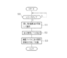
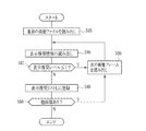
次に、3D静止画撮影モードでの画像の撮影及び記録処理について説明する。図5に示すように、レリーズボタン28が全押しされると(S10)、撮影部15L及び15Rによって同期して画像が撮影される(S11)。なお、3D静止画撮影モード時には、AF処理及びAE処理は、撮影部15L及び15Rのいずれか一方によって取得された画像信号に基づいて行われる。各撮影部15L及び15Rによって撮影された2つの画像は、デジタル信号処理部85による各種画像処理を経てワークメモリ39に書き込まれる。
Next, image capturing and recording processing in the 3D still image capturing mode will be described. As shown in FIG. 5, when the
視差量測定回路100及び立体表示適性判定回路101は、各撮影部15L及び15Rによって撮影された2つの画像による立体表示の適性を判定し、この適性を表す表示推奨レベルを決定する(S12)。立体表示適性は、第1撮影部15L及び第2撮影部15Rによって撮影した2つの画像の視差量に基づいて判定される。
The parallax
図4は、第1撮影部15L及び第2撮影部15Rにより撮影された画像103L及び103Rを示している。図6は、表示推奨レベル判定(S12)の手順を示す。視差量測定回路100は、ワークメモリ39に記憶されている画像103L及び103Rを読み出し(S15)、これらの画像103L及び103R間の視差量のヒストグラムF(ΔP)を算出する(S16)。
FIG. 4 shows images 103L and 103R photographed by the first photographing
図7に示すように、視差量測定回路100は、例えばブロックマッチング等の手法を用いて画像103L、103R間の相互に対応する対応点を抽出する(S24)。視差量測定回路100は、画像103L及び103Rのいずれか一方を基準画像とし、他方を探索画像と規定する。次いで、基準画像内からエッジ等の特徴点を複数抽出し、基準画像を複数の領域(ブロック)に分割する。そして、分割した領域をテンプレート画像として、探索画像の中からテンプレート画像に対応する領域を探索する。この対応領域の探索には、画素値の差の2乗和を求めるSSD(Sum of Squared Difference)、画素値の差の絶対値の総和を求めるSAD(Sum of Absolute Difference)等を用いることができる。視差量測定回路100は、見つかった探索領域内から基準画像の特徴点に対応する対応点を抽出する。
As shown in FIG. 7, the parallax
図4は、例えば画像103Lを基準画像、画像103Rを探索画像として特徴点及び対応点を抽出した例を示しており、基準画像103Lの特徴点P_L(xL,y)に対し、探索画像103Rの対応点P_R(xR,y)が抽出されている。視差量測定回路100は、特徴点P_L(xL,y)と対応点P_R(xR,y)との間の距離、例えば「xL−xR」の絶対値を視差量ΔPとして測定する(S25)。なお、図4では、図面の煩雑化を避けるため、特徴点及び対応点を1点ずつしか図示していないが、実際には多数の特徴点及び対応点が抽出され、各点の間の視差量が測定される。
FIG. 4 shows an example in which feature points and corresponding points are extracted using, for example, the image 103L as a reference image and the image 103R as a search image. The feature point P_L (xL, y) of the reference image 103L is extracted from the search image 103R. Corresponding point P_R (xR, y) is extracted. The parallax
次いで、視差量測定回路100は、測定した視差量ΔPと、その発生頻度Fとのヒストグラム(統計量)F(ΔP)を算出する(S26)。ヒストグラムF(ΔP)の算出は、例えば、同じ値の視差量が測定されたときに、その視差量の頻度Fに1を加算する。視差量の測定(S24)からヒストグラムの算出(S26)までの各ステップは、基準画像103Lの全ブロックにおいて対応点の抽出が完了するまで繰り返される(S27、S28)。
Next, the parallax
図8〜11は、視差量測定回路100によって算出された視差量ヒストグラムの1例である。図8は、例えば人物と景色等の背景とからなるシーンを撮影した画像のヒストグラムである。このようなシーンでは、主要な被写体である人物とともに背景からも多数の特徴点及び対応点が抽出されるため、多数の視差量において発生頻度のピークが得られる。また、図9は、例えば建物と、のっぺりとした均一なテクスチャの背景とからなるシーンを撮影した画像のヒストグラムである。このようなシーンでは、主要な被写体である建物から多数の特徴点及び対応点が抽出され、背景からの抽出数が少なくなるため、視差量の発生頻度のピークは限定的になる。
8 to 11 are examples of the parallax amount histogram calculated by the parallax
図10は、例えば全体的に絵柄が煩雑で情報量の多いシーンを撮影した画像の視差量ヒストグラムである。このようなシーンでは、画像全体において多数の特徴点及び対応点が抽出されるため、多数の視差量において発生頻度のピークが得られる。また、図11は、例えば人物と、のっぺりとした均一なテクスチャの背景とからなるシーンを撮影した画像のヒストグラムである。このようなシーンでは、主要な被写体である人物から多数の特徴点及び対応点が抽出され、背景からの抽出数が少なくなるため、視差量の発生頻度のピークは限定的になる。 FIG. 10 is a parallax amount histogram of an image obtained by shooting a scene having a complicated design and a large amount of information , for example. In such a scene, since a large number of feature points and corresponding points are extracted in the entire image, a peak of occurrence frequency is obtained in a large number of parallax amounts. Further, FIG. 11 is a histogram of an image obtained by photographing a scene including, for example, a person and a background having a uniform texture. In such a scene, a large number of feature points and corresponding points are extracted from the person who is the main subject, and the number of extractions from the background is reduced, so that the peak frequency of occurrence of parallax is limited.
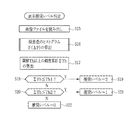
図6に示すように、立体表示適性判定回路101は、算出した視差量ヒストグラムに基づいて、閾値Th以上の視差量の頻度累計ΣThを算出する(S17)。例えば、図10に示す視差量ヒストグラムを用いて頻度累計ΣThを算出する場合、立体表示適性判定回路101は、視差量ΔPのピーク値を閾値Thとして設定し、この閾値Th以上の頻度Fの累計である頻度累計ΣThを算出する。閾値Thは、視差量ΔPのピーク値に限定されず、複数あるピークの最低値、平均値でもよい。また、シーンに応じて閾値Thの決定基準を変化させてもよい。
As illustrated in FIG. 6, the stereoscopic display
立体表示適性判定回路101は、頻度累計ΣThと、ROM37に記憶された頻度累計閾値Th1、Th2とを比較する。なお、頻度累計閾値Th1、h2は、Th1<Th2の関係にある。頻度累計閾値Th1、Th2は、例えば、頻度累計と目の疲労度との関係を官能試験等により明らかにして求めた値を用いることができる。また、2種類の頻度累計閾値を用いているのは、頻度累計ΣThから3段階の表示推奨レベルを設定するためであり、表示推奨レベルのレベル数に応じて頻度累計閾値の数を変化させてもよい。
The stereoscopic display
立体表示適性判定回路101は、最初に頻度累計ΣThと頻度累計閾値Th1とを比較する(S18)。頻度累計ΣThが頻度累計閾値Th1よりも小さい場合には、画像全体の視差量が小さく、目の疲労が小さいことが推定されるため、推奨レベルの高い「表示推奨レベル2」がその画像に設定される(S19)。
The stereoscopic display
また、立体表示適性判定回路101は、頻度累計ΣThが頻度累計閾値Th1よりも大きい場合には、頻度累計ΣThと頻度累計閾値Th2とを比較する(S20)。頻度累計ΣThが頻度累計閾値Th2よりも小さい場合には、画像全体としての視差量が平均的であることが推定されるため、推奨レベルが中程度の「表示推奨レベル1」がその画像に設定される(S21)。
If the frequency cumulative ΣTh is greater than the frequency cumulative threshold Th1, the stereoscopic display
更に、立体表示適性判定回路101は、頻度累計ΣThが頻度累計閾値Th2よりも大きい場合には、画像全体としての視差量が大きく、目が疲れやすいことが推定されるため、推奨レベルが低い「表示推奨レベル0」がその画像に設定される(S22)。
Furthermore, when the frequency cumulative ΣTh is larger than the frequency cumulative threshold Th2, the stereoscopic display
表示推奨レベル判定の終了後、画像103L,103Rは、それぞれ圧縮・伸張処理部97L及び97Rによって圧縮され、1つの3D静止画ファイルに格納されてメモリカード29に記録される。また、3D画像ファイルには、2視点の圧縮画像データとともに、被写体距離情報、撮影レンズ51L及び51Rの基線長(間隔)及び輻輳角に関する情報が格納される(S13)。
After the determination of the recommended display level, the images 103L and 103R are compressed by the compression / decompression processing units 97L and 97R, stored in one 3D still image file, and recorded on the
図12は、3D静止画撮影により作成された3D静止画ファイル110の構成を示している。画像ファイルである3D静止画ファイル110は、左側画像103L及び右側画像103Rの画像データ111L及び111Rと、画像データ111L及び111Rの先頭に配された「ヘッダ1」112L、「ヘッダ2」112Rとから構成されている。
FIG. 12 shows the configuration of a 3D still image file 110 created by 3D still image shooting. The 3D still image file 110 that is an image file includes
「ヘッダ1」112Lは、データ先頭から「ヘッダ2」112Rの先頭までのオフセット量と、左側画像データ111Lの属性とが記録されている。なお、「OR−1」は、3D静止画ファイル110への格納時に左側画像データ111Lに付与される画像名の一例である。
In “Header 1” 112L, an offset amount from the top of the data to the top of “Header 2” 112R and the attribute of the
左側画像データ111Lの属性には、視点順序、3D撮影条件、2D撮影条件、表示推奨レベルが含まれている。視点順序とは、左右いずれの画像であるかを表しており、左側画像には「視点順序1」が付与され、右側画像には「視点順序2」が付与される。3D撮影条件は、例えば、第1撮影部15L及び第2撮影部15Rの基線長、輻輳角、被写体距離情報であり、立体表示時に必要な情報である。2D撮影条件は、シャッタスピード、露出であり、再生表示及びプリント時の画質調整に必要な情報である。表示推奨レベルは、立体表示適性判定回路101によって判定されたレベル値であり、フレーム12等で立体表示を行う際に参照される。
Attributes of the
「ヘッダ2」112Rには、右側画像データ111Rの属性が記録されている。属性の項目は、視点順序及び2D撮影条件であり、内容的には「ヘッダ1」112Lと共通している。
In “Header 2” 112R, the attribute of the
次に、3D動画撮影モードでの表示推奨レベル判定と、撮影後に作成される3D動画ファイルの構成について説明する。詳しい説明は省略するが、3D動画撮影を行うと、ワークメモリ39には、第1撮影部15L及び第2撮影部15Rにより撮影された2つの動画が記憶される。図13に示すように、視差量測定回路100は、ワークメモリ39に記憶されている2つの動画から、最初の画像フレームをそれぞれ読み出す。(S30)。
Next, the display recommended level determination in the 3D moving image shooting mode and the configuration of the 3D moving image file created after shooting will be described. Although detailed description is omitted, when 3D moving image shooting is performed, the
視差量測定回路100は、読み出した2つの画像フレーム間の視差量のヒストグラムF(ΔP)を算出し(S31)、立体表示適性判定回路101は、算出した視差量ヒストグラムに基づいて、閾値Th以上の視差量の頻度累計ΣThを算出する(S32)。次いで、立体表示適性判定回路101は、頻度累計ΣThと、頻度累計閾値Th1、Th2とを比較して、その画像フレームの表示推奨レベルを判定する(S33〜S37)。なお、ステップS31〜S37については、3D静止画撮影時と同様であるため、詳しい説明は省略する。
The parallax
視差量測定回路100は、ワークメモリ39に記憶されている2つの動画に続く画像フレームがあるか確認し(S38)、続きの画像フレームが存在する場合には次の画像フレームを読み出し(S39)、表示推奨レベルを判定する(ステップS31〜S39)。このように、3D動画撮影モード時には、画像フレームごとに表示推奨レベルが設定される。
The parallax
図14は、3D動画撮影により作成された3D動画ファイル115の構成を示している。画像ファイルである3D動画ファイル115は、大きく分けて、3D動画ファイル115の構成等を表すヘッダ領域116と、動画データを表す画像データ領域117とから構成されている。ヘッダ領域116は、ストリーム情報118と撮影条件情報119とから構成されている。画像データ領域117は、ストリームデータ1〜3を1つにまとめた複数のチャンクデータ120a〜120nから構成されている。
FIG. 14 shows a configuration of a 3D moving image file 115 created by 3D moving image shooting. The 3D moving image file 115 that is an image file is roughly divided into a
ストリーム情報118は、ストリーム定義123とストリーム属性124とから構成されている。ストリーム定義123は、チャンクデータ120a〜120nの各ストリームデータ1〜3の内容を定義している。例えば、ストリーム定義123は、ストリームデータ1、2の内容が、3D動画撮影の左または右画像、チャンクデータ全体における再生時のデータ量、先頭アドレスであることを定義している。また、ストリーム定義123は、ストリームデータ3の内容が、左右の画像からなる立体表示の表示推奨レベルであることを定義している。
The
ストリーム属性124は、3D動画ファイル115全体の属性を表しており、例えば、3D動画ファイル115の作成時に付与されたストリームID、撮影時の解像度、圧縮方式、表示次元、1つのチャンクデータ当たりのフレーム数等が記録されている。
The
撮影条件情報119は、3D動画撮影モードの撮影条件が記録されている。例えば、視点数、撮影部15L、15Rの基線長及び輻輳角等である。視点数は、本実施形態のカメラ11の場合は「2」であり、基線長及び輻輳角は、3D動画撮影時に設定された値が記録される。
The
チャンクデータ120a〜120nを構成する「ストリームデータ1」121a、「ストリームデータ2」121bには、左側画像データ、右側画像データに関連する情報が記録されている。その情報とは、例えば、ストリーム属性124と同一のストリームIDと、チャンクデータ内におけるデータ長と、1フレーム分の画像データである。また、「ストリームデータ3」121cには、ストリームデータ1、2と同様にストリームID及びデータ長と、表示推奨レベルとが記録されている。
In the “stream data 1” 121a and “stream data 2” 121b constituting the chunk data 120a to 120n, information related to the left image data and the right image data is recorded. The information is, for example, the same stream ID as the
次に、フレーム12について説明する。図15に示すように、フレーム12は、操作部130からの入力に基づき所定の制御プログラムに従ってカメラ11全体の動作を統括制御するCPU131を備えている。CPU131には、ROM132、EEPROM133及びワークメモリ134が接続されている。ROM132には、CPU131が実行する制御プログラム及び制御に必要な各種データ等が格納される。EEPROM133には、ユーザ設定情報等のフレーム12の動作に関する各種設定情報等が格納される。ワークメモリ134は、CPU130の演算作業用領域及び画像ファイルの一時記憶領域を含んでいる。CPU131は、ROM132に格納されている制御プログラムにしたがって動作することにより、本発明の出力制御手段に相当する機能を発揮する。
Next, the frame 12 will be described. As shown in FIG. 15, the frame 12 includes a
CPU131には、メモリカード29から画像ファイルを読み込むメモリコントローラ137が接続されている。メモリコントローラ137は、図1に示すカードスロット139内に設けられI/F140を介してメモリカード29にアクセスし、再生を支持された画像ファイルを読み込んでワークメモリ134に一時的に格納する。伸張処理部141は、ワークメモリ134内に格納された画像ファイルを非圧縮のY/C信号に伸張する。
A
表示コントローラ144は、ワークメモリ134内のY/C信号を読み出してYC−RGB変換部145に出力する。YC−RGB変換部145は、表示コントローラ144から入力されたY/C信号をR、G、B信号に変換してドライバ146を介してLCDパネル17に出力する。これにより、LCDパネル17にカメラ11で撮影した画像が再生表示される。
The
LCDパネル17は、例えば、パララックスバリア式、あるいはレンチキュラーレンズ式の3Dモニタである。LCDパネル17の詳細な構造は図示しないが、LCDパネル17は、その表面にパララックスバリア表示層を備えている。LCDパネル17は、立体表示を行う際に、パララックスバリア表示層に光透過部と光遮蔽部とが交互に所定のピッチで並んだパターンからなるパララックスバリアを発生させるとともに、その下層の画像表示面に左右の像を示す短冊状の画像断片を交互に配列して表示することで立体視を可能にする。
The
なお、立体視を可能にする表示装置の構成は、スリットアレイシートを用いるパララックス方式に限られる必然性はなく、レンチキュラーレンズシートを用いるレンチキュラー方式、マイクロレンズアレイシートを用いるインテグラルフォトグラフィ方式、干渉現象を用いるホログラフィー方式などが採用されてもよい。 Note that the configuration of the display device that enables stereoscopic viewing is not necessarily limited to the parallax method using the slit array sheet, the lenticular method using the lenticular lens sheet, the integral photography method using the micro lens array sheet, and the interference. A holographic method using a phenomenon may be employed.
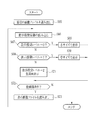
次に、フレーム12によって、3D静止画及び3D動画を再生する第1実施形態について説明する。図16に示すように、CPU131は、メモリコントローラ137を制御してメモリカード29から最初の3D静止画ファイル110を読み出す(S45)。CPU131は、読み出した3D静止画ファイル110の表示推奨情報を読み出し(S46)、表示推奨レベルが「1」以上のときには、その3D静止画ファイル110をEEPROM133内に格納されている表示推奨リストLに登録する(S47,S48)。
Next, a first embodiment in which a 3D still image and a 3D moving image are played back using the frame 12 will be described. As shown in FIG. 16, the
また、3D静止画ファイル110の表示推奨レベルが「1」以下のときには、次の3D静止画ファイル110を読み出し(S47、S49)、ステップS46,S47を実行する。CPU131は、メモリカード29内に記憶されている全ての3D静止画ファイル110について、ステップS46〜S49を繰り返す(S50)。
When the recommended display level of the 3D still image file 110 is “1” or less, the next 3D still image file 110 is read (S47, S49), and steps S46 and S47 are executed. The
また、3D動画ファイル115については、図17に示すように、CPU131が最初の画像フレームを読み出し(S52)、表示推奨レベルを確認する(S53)。次の画像フレームが存在する場合には(S54)、それを読み出して表示推奨レベルを確認する(S55、S53)。CPU131は、全ての画像フレームの表示推奨レベルを確認した後、表示推奨レベルの平均値を算出し(S56)、この平均値が「1」以上のときには、その3D動画ファイル115を表示推奨リストLに登録する(S57、S58)。なお、CPU131は、メモリカード29内に記憶されている全ての3D動画ファイル115についてもファイルの推奨表示レベルを確認する。
As for the 3D moving image file 115, as shown in FIG. 17, the
CPU131は、メモリカード29内の全ての画像ファイルの表示推奨レベルの確認後、図18に示すように、EEPROM133から表示推奨リストLを読み出し(S60)、表示推奨リストLに登録されている画像ファイルのサムネイル画像をLCDパネル17に一覧表示させる(S61)。CPU131は、操作部130により、LCDパネル17に一覧表示されているサムネイル画像を選択できるようにし(S62)、選択されたサムネイル画像に該当する3D静止画ファイル110または3D動画ファイル115を順に立体表示させる(S63)。
After confirming the recommended display level of all image files in the
これによれば、表示推奨レベルが「1」以上の立体画像のみを表示させることができるので、立体表示適性が低い画像が観察されることによる観察者の目の疲労を防止することができる。なお、表示推奨リストLへの登録条件となる表示推奨レベルは、ユーザが任意に選択できるようにしてもよい。 According to this, since only a stereoscopic image having a recommended display level of “1” or more can be displayed, it is possible to prevent the eyestrain of the observer due to the observation of an image with low stereoscopic display suitability. Note that the recommended display level as a registration condition in the recommended display list L may be arbitrarily selected by the user.
次に、表示推奨レベルに応じて表示サイズを切り換え、全ての画像を表示させる第2実施形態について説明する。図19に示すように、CPU131は、メモリカード29から最初の3D静止画ファイル110を読み出し(S65)、3D静止画ファイル110の表示推奨情報を確認する(S66〜S68)。
Next, a second embodiment in which the display size is switched according to the recommended display level and all images are displayed will be described. As shown in FIG. 19, the
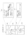
CPU131は、3D静止画ファイル110の表示推奨レベルが「0」のときに、その立体画像を図20に示す小サイズ150でLCDパネル17に表示させる(S67、S69)。また、3D静止画ファイル110の表示推奨レベルが「1」のときには、その立体画像を中サイズ151でLCDパネル17に表示させる(S68、S70)。更にまた、3D静止画ファイル110の表示推奨レベルが「2」のときには、その立体画像をLCDパネル17に全画面サイズで表示させる(S71)。CPU131は、メモリカード29内に記憶されている全ての3D静止画ファイル110について、ステップS66〜S71を繰り返す(S72、S73)。
When the recommended display level of the 3D still image file 110 is “0”, the
また、3D動画ファイル115については、CPU131が全ての画像フレームの表示推奨レベルを確認し、その平均値に基づいて表示サイズを切り換える。
For the 3D moving image file 115, the
これによれば、表示推奨レベルが低い画像は小さなサイズで立体表示されるので、観察者の目の疲労を防止することができる。また、表示推奨レベルが高い画像は全画面サイズで立体表示されるので、高画質な立体画像を大きなサイズで観察させることができる。 According to this, since an image with a low display recommendation level is stereoscopically displayed in a small size, it is possible to prevent eyestrain of the observer. In addition, since an image with a high display recommendation level is stereoscopically displayed at the full screen size, a high-quality stereoscopic image can be observed at a large size.
なお、第2実施形態では、表示推奨レベルに応じて表示サイズを切り換えたが、例えば表示推奨レベルに応じて表示時間を切り換えてもよい。この場合、表示推奨レベル「0」のときには、観察者の目の疲労を系得源するため表示時間を短くし、表示推奨レベルがたかくなるにしたがって徐々に表示時間を長くするのが好ましい。 In the second embodiment, the display size is switched according to the recommended display level. However, for example, the display time may be switched according to the recommended display level. In this case, when the recommended display level is “0”, it is preferable to shorten the display time in order to obtain the system fatigue of the eyes of the observer, and gradually increase the display time as the recommended display level increases.
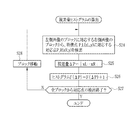
次に、3D動画ファイル115の再生に関する第3実施形態について説明する。動画は、複数の画像フレームを連続して表示することにより表現されているため、各画像フレーム間において視差量に大きな差が生じていると、観察者はその視差量に合わせて輻輳距離を合わせようとするため、目の疲労が大きくなる。そこで、本実施形態では、表示推奨レベルが低い画像フレームの再生を中止し、この再生が中止されている間は、直前に再生された画像の表示を継続することにより、目の疲労を軽減している。 Next, a third embodiment relating to reproduction of the 3D moving image file 115 will be described. Since moving images are expressed by displaying multiple image frames in succession, if there is a large difference in the amount of parallax between image frames, the observer adjusts the convergence distance according to the amount of parallax. As a result, eye fatigue increases. Therefore, in this embodiment, the reproduction of an image frame with a low recommended display level is stopped, and while the reproduction is stopped, the display of the image reproduced immediately before is continued to reduce eye fatigue. ing.
図21に示すように、CPU131は、3D動画ファイル115の再生時に、最初の画像フレームを読み出し(S75)、読み出した画像フレームの表示推奨レベルを確認する(S76、S77)。表示推奨レベルが「1」以上のときには、その画像フレームをLCDパネル17に表示させる(S78)。また、表示推奨レベルが「1」以下のときには、次の画像フレームを読み出し(S79)、ステップS76、S77を実行する。この場合、直前の画像フレームによる表示が継続される。CPU131は、3D動画ファイル115の画像フレーム全てについて、ステップS76〜S78を実行する(S80)。
As shown in FIG. 21, when reproducing the 3D moving image file 115, the
上記実施形態では、各画像フレームを読み出すごとに表示するか否かを判定しているが、例えば、最初に全ての画像フレームの表示推奨レベルを確認し、この確認結果に基づいて3D動画ファイル115を編集し、再生専用の動画ファイルを一時的に作成してもよい。これによれば、表示推奨レベルの低い画像フレームが続くような3D動画ファイル115であっても、その内容に応じてより目の疲労が少ない立体表示を行うことができる。 In the above-described embodiment, it is determined whether or not each image frame is displayed. For example, first, the recommended display level of all image frames is confirmed, and the 3D moving image file 115 is based on the confirmation result. May be edited to temporarily create a playback-only movie file. According to this, even in the case of the 3D moving image file 115 in which an image frame having a low recommended display level continues, stereoscopic display with less eye fatigue can be performed according to the content.
次に、メモリカード29に記憶されている画像ファイルの表示推奨レベルがどのような分布になっているかを容易に確認できるようにした第4実施形態について説明する。上記第1〜第3実施形態全てにおいて、ユーザが表示推奨レベルに基づいて任意に立体表示の内容を設定できることが好ましい。この任意設定を実現するには、メモリカード29に記憶されている画像ファイルの表示推奨レベルがどのような分布になっているか確認できることが好ましい。
Next, a fourth embodiment in which the distribution of recommended display levels of image files stored in the
図22は、メモリカード29内の画像ファイルの表示推奨レベルの確認後にLCDパネル17に表示されるグラフの1例を示している。グラフ155は、縦軸に表示推奨レベル、横軸に画像ファイル数がプロットされているため、画像ファイル数と表示推奨レベルとの相関を容易に把握することができる。これにより、表示推奨レベルに基づいて表示内容を設定するだけでなく、画像ファイル数と表示推奨レベルとの相関を考慮して表示内容を設定することができる。
FIG. 22 shows an example of a graph displayed on the
また、グラフ155の上に2本の範囲指定バー156を表示させ、この範囲指定バー156によって指定された範囲内の表示推奨レベルの画像が表示されるようにしてもよい。範囲指定バー156を用いた表示設定を用いる場合、表示推奨レベルのレベル数を更に増やしてもよい。上記第1〜第3実施形態のように、表示推奨レベルに基づいて表示内容を設定する場合、表示推奨レベル数が多いとその選択自体が難しくなる。しかし、範囲指定バー156を用いた場合には、表示推奨レベルと画像ファイル数とのバランスに基づいて設定することができるので、表示推奨レベルのレベル数が増えることによる弊害は生じない。
Further, two range designation bars 156 may be displayed on the graph 155, and an image having a recommended display level within the range designated by the
上記各実施形態では、立体画像出力装置としてデジタルフォトフレーム12を用いたが、本発明は、立体表示が可能なモニタ、テレビ等にも適用可能である。また、レンチキュラーレンズを用いた立体プリントを作成するプリンタに本発明を適用することも可能である。また、フレーム12による立体画像表示についての第1〜第4実施形態は、カメラ11の画像表示部32による立体表示に適用してもよい。
In each of the embodiments described above, the digital photo frame 12 is used as the stereoscopic image output device, but the present invention can also be applied to a monitor, a television, and the like capable of stereoscopic display. The present invention can also be applied to a printer that creates a three-dimensional print using a lenticular lens. In addition, the first to fourth embodiments regarding the stereoscopic image display by the frame 12 may be applied to the stereoscopic display by the
10 立体画像撮影・再生システム
11 デジタルカメラ
12 デジタルフォトフレーム
15L 第1撮影部
15R 第2撮影部
35 メインCPU
100 視差量測定回路
101 立体表示適性判定回路
110 3D静止画ファイル
115 3D動画ファイル
131 CPU
155 グラフ
DESCRIPTION OF SYMBOLS 10 Stereoscopic image photography / reproduction system 11 Digital camera 12
DESCRIPTION OF
155 graph
Claims (13)
前記統計量に基づいて、前記シーンの内容に応じて切り替えられる閾値以上の視差量の発生頻度の累計である頻度累計を算出し、前記頻度累計に基づいて前記複数の画像による立体表示の適性を判定し、この適性を表す少なくとも2段階以上の表示推奨レベルから判定結果に適合した表示推奨レベルを決定する立体表示適性判定手段と、
前記複数の画像に前記表示推奨レベルを表す表示推奨情報を付加し、前記複数の画像を記憶する画像記憶手段とを備えたことを特徴とする立体画像記録装置。 Corresponding points corresponding to each other are extracted from a plurality of images obtained by photographing the same scene from different viewpoints for displaying a stereoscopic image, the amount of parallax between the corresponding points is measured, and the statistics of the amount of parallax and the frequency of occurrence thereof are obtained. Parallax amount measuring means;
Based on the statistic, calculate a frequency total that is the total frequency of occurrence of the parallax amount equal to or greater than a threshold that is switched according to the content of the scene , and determine the suitability of stereoscopic display by the plurality of images based on the frequency total. 3D display suitability determination means for determining and determining a display recommendation level suitable for the determination result from at least two or more display recommended levels representing this suitability;
A stereoscopic image recording apparatus comprising: image recommendation means for adding display recommendation information representing the recommended display level to the plurality of images and storing the plurality of images.
前記統計量に基づいて、前記シーンの内容に応じて切り替えられる閾値以上の視差量の発生頻度の累計である頻度累計を算出し、前記頻度累計に基づいて前記複数の画像による立体表示の適性を判定し、この適性を表す少なくとも2段階以上の表示推奨レベルから判定結果に適合した表示推奨レベルを決定する立体表示適性判定工程と、
前記複数の画像に前記表示推奨レベルを表す表示推奨情報を付加し、前記複数の画像を記憶する記憶工程とを備えたことを特徴とする立体画像記録方法。 Corresponding points corresponding to each other are extracted from a plurality of images obtained by photographing the same scene from different viewpoints for displaying a stereoscopic image, the amount of parallax between the corresponding points is measured, and the statistics of the amount of parallax and the frequency of occurrence thereof are obtained. A parallax measurement process;
Based on the statistic, calculate a frequency total that is the total frequency of occurrence of the parallax amount equal to or greater than a threshold that is switched according to the content of the scene , and determine the suitability of stereoscopic display by the plurality of images based on the frequency total. A stereoscopic display suitability determination step of determining and determining a recommended display level suitable for the determination result from at least two or more display recommended levels representing this suitability;
A stereoscopic image recording method comprising: a storage step of adding display recommendation information representing the recommended display level to the plurality of images and storing the plurality of images.
前記表示推奨情報から前記複数の画像による立体表示適性を判断する工程と、
前記立体表示適性に基づいて、前記複数の画像による立体画像の出力状態を切り換える工程とを備えたことを特徴とする立体画像出力方法。 A step of reading the display recommendation information added to the plurality of images recorded by the stereoscopic image recording method according to claim 6, wherein,
Determining the suitability of stereoscopic display by the plurality of images from the display recommendation information;
A stereoscopic image output method comprising: switching a stereoscopic image output state of the plurality of images based on the stereoscopic display suitability.
前記統計量に基づいて、前記シーンの内容に応じて切り替えられる閾値以上の視差量の発生頻度の累計である頻度累計を算出し、前記頻度累計に基づいて前記複数の画像による立体表示の適性を判定し、この適性を表す少なくとも2段階以上の表示推奨レベルから判定結果に適合した表示推奨レベルを決定する立体表示適性判定手段と、
前記複数の画像に前記表示推奨レベルを表す表示推奨情報を付加し、前記複数の画像を記憶する画像記憶手段とを備えた立体画像記録装置と、
異なる視点から撮影した複数の画像に付加されている表示推奨情報を読み取り、前記表示推奨情報から前記複数の画像による立体表示適性を判断し、前記立体表示適性に基づいて、前記複数の画像により立体画像を出力する出力手段の出力状態を切り換える出力制御手段を備えた立体画像出力装置と、
を備えたことを特徴とする立体画像記録出力システム。 Corresponding points corresponding to each other are extracted from a plurality of images obtained by photographing the same scene from different viewpoints for displaying a stereoscopic image, the amount of parallax between the corresponding points is measured, and the statistics of the amount of parallax and the frequency of occurrence thereof are obtained. Parallax amount measuring means;
Based on the statistic, calculate a frequency total that is the total frequency of occurrence of the parallax amount equal to or greater than a threshold that is switched according to the content of the scene , and determine the suitability of stereoscopic display by the plurality of images based on the frequency total. 3D display suitability determination means for determining and determining a display recommendation level suitable for the determination result from at least two or more display recommended levels representing this suitability;
A stereoscopic image recording apparatus comprising image storage means for adding display recommendation information representing the recommended display level to the plurality of images and storing the plurality of images;
The display recommendation information added to the plurality of images taken from different viewpoints is read, the three-dimensional display suitability of the plurality of images is determined from the display recommendation information, and the three-dimensional display by the plurality of images is performed based on the three-dimensional display suitability. A stereoscopic image output device comprising output control means for switching the output state of the output means for outputting an image;
A stereoscopic image recording / outputting system comprising:
Priority Applications (4)
| Application Number | Priority Date | Filing Date | Title |
|---|---|---|---|
| JP2009169293A JP5249149B2 (en) | 2009-07-17 | 2009-07-17 | Stereoscopic image recording apparatus and method, stereoscopic image output apparatus and method, and stereoscopic image recording and output system |
| EP10251205.0A EP2278820A3 (en) | 2009-07-17 | 2010-07-05 | Stereoscopic image recording apparatus and method, stereoscopic image outputting apparatus and method, and stereoscopic image recording outputting system |
| US12/831,470 US20110012995A1 (en) | 2009-07-17 | 2010-07-07 | Stereoscopic image recording apparatus and method, stereoscopic image outputting apparatus and method, and stereoscopic image recording outputting system |
| CN201010231448.6A CN101959075B (en) | 2009-07-17 | 2010-07-15 | Stereoscopic image recording apparatus and method, stereoscopic image outputting apparatus and method, and stereoscopic image recording outputting system |
Applications Claiming Priority (1)
| Application Number | Priority Date | Filing Date | Title |
|---|---|---|---|
| JP2009169293A JP5249149B2 (en) | 2009-07-17 | 2009-07-17 | Stereoscopic image recording apparatus and method, stereoscopic image output apparatus and method, and stereoscopic image recording and output system |
Publications (2)
| Publication Number | Publication Date |
|---|---|
| JP2011024122A JP2011024122A (en) | 2011-02-03 |
| JP5249149B2 true JP5249149B2 (en) | 2013-07-31 |
Family
ID=42937381
Family Applications (1)
| Application Number | Title | Priority Date | Filing Date |
|---|---|---|---|
| JP2009169293A Active JP5249149B2 (en) | 2009-07-17 | 2009-07-17 | Stereoscopic image recording apparatus and method, stereoscopic image output apparatus and method, and stereoscopic image recording and output system |
Country Status (4)
| Country | Link |
|---|---|
| US (1) | US20110012995A1 (en) |
| EP (1) | EP2278820A3 (en) |
| JP (1) | JP5249149B2 (en) |
| CN (1) | CN101959075B (en) |
Families Citing this family (27)
| Publication number | Priority date | Publication date | Assignee | Title |
|---|---|---|---|---|
| US10499029B2 (en) | 2007-01-09 | 2019-12-03 | Capso Vision Inc | Methods to compensate manufacturing variations and design imperfections in a display device |
| KR101686168B1 (en) * | 2010-03-10 | 2016-12-22 | 주식회사 티엘아이 | Method for constituting stereoscopic moving picture file |
| JP5243477B2 (en) | 2010-04-13 | 2013-07-24 | パナソニック株式会社 | Blur correction apparatus and blur correction method |
| EP2587812A4 (en) * | 2010-06-24 | 2014-02-26 | Korea Electronics Technology | Method for configuring stereoscopic moving picture file |
| JPWO2012023168A1 (en) * | 2010-08-19 | 2013-10-28 | パナソニック株式会社 | Stereoscopic imaging device and stereoscopic imaging method |
| JP5582945B2 (en) * | 2010-09-28 | 2014-09-03 | キヤノン株式会社 | Imaging system |
| JP5614268B2 (en) * | 2010-12-09 | 2014-10-29 | ソニー株式会社 | Image processing apparatus, image processing method, and program |
| JP5668466B2 (en) * | 2010-12-28 | 2015-02-12 | ソニー株式会社 | Image processing apparatus, control method thereof, and program |
| US20120200676A1 (en) * | 2011-02-08 | 2012-08-09 | Microsoft Corporation | Three-Dimensional Display with Motion Parallax |
| JP5492311B2 (en) * | 2011-02-08 | 2014-05-14 | 富士フイルム株式会社 | Viewpoint image generation apparatus, viewpoint image generation method, and stereoscopic image printing apparatus |
| TW201245768A (en) * | 2011-03-29 | 2012-11-16 | Sony Corp | Image pickup apparatus, image pickup device, image processing method, aperture control method, and program |
| JP5791328B2 (en) * | 2011-03-30 | 2015-10-07 | Necパーソナルコンピュータ株式会社 | 3D image processing method and 3D image processing apparatus |
| CN102760234B (en) | 2011-04-14 | 2014-08-20 | 财团法人工业技术研究院 | Depth image acquisition device, system and method |
| TWI463244B (en) * | 2011-04-14 | 2014-12-01 | Ind Tech Res Inst | System, device and method for acquiring depth image |
| CN102289225A (en) * | 2011-04-22 | 2011-12-21 | 钰创科技股份有限公司 | Universal sequence bus device applied to network camera and control method thereof |
| WO2012147329A1 (en) * | 2011-04-28 | 2012-11-01 | パナソニック株式会社 | Stereoscopic intensity adjustment device, stereoscopic intensity adjustment method, program, integrated circuit, and recording medium |
| US20140085435A1 (en) * | 2011-05-19 | 2014-03-27 | Thomason Licensing | Automatic conversion of a stereoscopic image in order to allow a simultaneous stereoscopic and monoscopic display of said image |
| JP2013005238A (en) * | 2011-06-16 | 2013-01-07 | Sony Corp | Three-dimensional image processing apparatus, three-dimensional image processing method, display apparatus, and computer program |
| JP2013064996A (en) * | 2011-08-26 | 2013-04-11 | Nikon Corp | Three-dimensional image display device |
| JP5658119B2 (en) * | 2011-09-30 | 2015-01-21 | Kddi株式会社 | Video evaluation apparatus, video evaluation method, and program |
| TWI514849B (en) * | 2012-01-11 | 2015-12-21 | Himax Tech Ltd | Calibration device used in stereoscopic display system and calibration method of the same |
| US20150215530A1 (en) * | 2014-01-27 | 2015-07-30 | Microsoft Corporation | Universal capture |
| US9319576B2 (en) * | 2014-01-29 | 2016-04-19 | Google Technology Holdings LLC | Multi-processor support for array imagers |
| JP6597041B2 (en) * | 2015-08-18 | 2019-10-30 | 富士ゼロックス株式会社 | Server apparatus and information processing system |
| EP3135189A1 (en) * | 2015-08-25 | 2017-03-01 | Capso Vision, Inc. | Methods to compensate manufacturing variations and design imperfections in a display device |
| CN106131448B (en) * | 2016-07-22 | 2019-05-10 | 石家庄爱赛科技有限公司 | The three-dimensional stereoscopic visual system of brightness of image can be automatically adjusted |
| WO2018223267A1 (en) * | 2017-06-05 | 2018-12-13 | Shanghaitech University | Method and system for hyperspectral light field imaging |
Family Cites Families (14)
| Publication number | Priority date | Publication date | Assignee | Title |
|---|---|---|---|---|
| JPH099300A (en) * | 1995-06-26 | 1997-01-10 | Matsushita Electric Ind Co Ltd | Three-dimensional display device |
| JP4149037B2 (en) | 1998-06-04 | 2008-09-10 | オリンパス株式会社 | Video system |
| JP2003018619A (en) * | 2001-07-03 | 2003-01-17 | Olympus Optical Co Ltd | Three-dimensional image evaluation apparatus and display using the same |
| CN1703915A (en) * | 2002-09-27 | 2005-11-30 | 夏普株式会社 | 3-D image display unit, 3-D image recording device and 3-D image recording method |
| JP4259913B2 (en) * | 2003-05-08 | 2009-04-30 | シャープ株式会社 | Stereoscopic image processing apparatus, stereoscopic image processing program, and recording medium recording the program |
| JP4469159B2 (en) * | 2003-11-06 | 2010-05-26 | 学校法人早稲田大学 | 3D image evaluation apparatus and 3D image tuner |
| US8009188B2 (en) * | 2005-02-28 | 2011-08-30 | Victor Company Of Japan, Ltd. | Video data processing apparatus utilizing viewer influence, picture reproducing apparatus, and computer programs related thereto |
| JP4730120B2 (en) * | 2005-02-28 | 2011-07-20 | 日本ビクター株式会社 | Video data processing device, video playback device, video data processing method, video playback method, program for executing these methods by computer, and recording medium |
| JP4673178B2 (en) * | 2005-10-06 | 2011-04-20 | 株式会社エヌアイデイ | Streaming image playback quality evaluation system |
| KR101185870B1 (en) * | 2005-10-12 | 2012-09-25 | 삼성전자주식회사 | Apparatus and method for processing 3 dimensional picture |
| US8073196B2 (en) * | 2006-10-16 | 2011-12-06 | University Of Southern California | Detection and tracking of moving objects from a moving platform in presence of strong parallax |
| KR20080076628A (en) * | 2007-02-16 | 2008-08-20 | 삼성전자주식회사 | Image display device for improving three-dimensional effect of stereo-scopic image and method thereof |
| JP2008219788A (en) * | 2007-03-07 | 2008-09-18 | Toshiba Corp | Stereoscopic image display device, and method and program therefor |
| JP2009135686A (en) * | 2007-11-29 | 2009-06-18 | Mitsubishi Electric Corp | Stereoscopic video recording method, stereoscopic video recording medium, stereoscopic video reproducing method, stereoscopic video recording apparatus, and stereoscopic video reproducing apparatus |
-
2009
- 2009-07-17 JP JP2009169293A patent/JP5249149B2/en active Active
-
2010
- 2010-07-05 EP EP10251205.0A patent/EP2278820A3/en not_active Withdrawn
- 2010-07-07 US US12/831,470 patent/US20110012995A1/en not_active Abandoned
- 2010-07-15 CN CN201010231448.6A patent/CN101959075B/en not_active Expired - Fee Related
Also Published As
| Publication number | Publication date |
|---|---|
| EP2278820A3 (en) | 2014-01-15 |
| JP2011024122A (en) | 2011-02-03 |
| CN101959075A (en) | 2011-01-26 |
| US20110012995A1 (en) | 2011-01-20 |
| CN101959075B (en) | 2015-05-27 |
| EP2278820A2 (en) | 2011-01-26 |
Similar Documents
| Publication | Publication Date | Title |
|---|---|---|
| JP5249149B2 (en) | Stereoscopic image recording apparatus and method, stereoscopic image output apparatus and method, and stereoscopic image recording and output system | |
| JP4692770B2 (en) | Compound eye digital camera | |
| US8885026B2 (en) | Imaging device and imaging method | |
| JP5449537B2 (en) | Stereoscopic image reproduction apparatus and method, stereoscopic imaging apparatus, and stereoscopic display apparatus | |
| EP2590421B1 (en) | Single-lens stereoscopic image capture device | |
| JP4686795B2 (en) | Image generating apparatus and image reproducing apparatus | |
| JP5371845B2 (en) | Imaging apparatus, display control method thereof, and three-dimensional information acquisition apparatus | |
| US20110234767A1 (en) | Stereoscopic imaging apparatus | |
| JP5814692B2 (en) | Imaging apparatus, control method therefor, and program | |
| US20100315517A1 (en) | Image recording device and image recording method | |
| CN102959974B (en) | Stereoscopic image reproducing device, its disparity adjustment method and camera | |
| US20130162764A1 (en) | Image processing apparatus, image processing method, and non-transitory computer-readable medium | |
| JP5486697B2 (en) | Stereoscopic video playback device, stereoscopic video playback program and recording medium thereof, stereoscopic display device, stereoscopic imaging device, and stereoscopic video playback method | |
| JP2011024003A (en) | Three-dimensional moving image recording method and apparatus, and moving image file conversion method and apparatus | |
| JP5449535B2 (en) | Stereo imaging device and control method thereof | |
| JP5449551B2 (en) | Image output apparatus, method and program | |
| WO2011086630A1 (en) | Image pickup device, image pickup method, program, and integrated circuit | |
| JP5750457B2 (en) | Stereoscopic video processing device, stereoscopic video processing program and recording medium therefor, stereoscopic imaging device, and stereoscopic video processing method | |
| JP5466773B2 (en) | Stereoscopic video playback device, stereoscopic video playback program and recording medium thereof, stereoscopic display device, stereoscopic imaging device, and stereoscopic video playback method | |
| JP2011097451A (en) | Three-dimensional image display device and method | |
| JP5580486B2 (en) | Image output apparatus, method and program | |
| JP2012124650A (en) | Imaging apparatus, and imaging method | |
| JP2011082757A (en) | Display mode determination device and method, and imaging device and method |
Legal Events
| Date | Code | Title | Description |
|---|---|---|---|
| A621 | Written request for application examination |
Free format text: JAPANESE INTERMEDIATE CODE: A621 Effective date: 20111208 |
|
| A977 | Report on retrieval |
Free format text: JAPANESE INTERMEDIATE CODE: A971007 Effective date: 20120921 |
|
| A131 | Notification of reasons for refusal |
Free format text: JAPANESE INTERMEDIATE CODE: A131 Effective date: 20121010 |
|
| A521 | Request for written amendment filed |
Free format text: JAPANESE INTERMEDIATE CODE: A523 Effective date: 20121207 |
|
| TRDD | Decision of grant or rejection written | ||
| A01 | Written decision to grant a patent or to grant a registration (utility model) |
Free format text: JAPANESE INTERMEDIATE CODE: A01 Effective date: 20130313 |
|
| A61 | First payment of annual fees (during grant procedure) |
Free format text: JAPANESE INTERMEDIATE CODE: A61 Effective date: 20130411 |
|
| R150 | Certificate of patent or registration of utility model |
Ref document number: 5249149 Country of ref document: JP Free format text: JAPANESE INTERMEDIATE CODE: R150 Free format text: JAPANESE INTERMEDIATE CODE: R150 |
|
| FPAY | Renewal fee payment (event date is renewal date of database) |
Free format text: PAYMENT UNTIL: 20160419 Year of fee payment: 3 |
|
| R250 | Receipt of annual fees |
Free format text: JAPANESE INTERMEDIATE CODE: R250 |
|
| R250 | Receipt of annual fees |
Free format text: JAPANESE INTERMEDIATE CODE: R250 |
|
| R250 | Receipt of annual fees |
Free format text: JAPANESE INTERMEDIATE CODE: R250 |
|
| R250 | Receipt of annual fees |
Free format text: JAPANESE INTERMEDIATE CODE: R250 |
|
| R250 | Receipt of annual fees |
Free format text: JAPANESE INTERMEDIATE CODE: R250 |