JP5246508B2 - Control device for motor drive device - Google Patents
Control device for motor drive device Download PDFInfo
- Publication number
- JP5246508B2 JP5246508B2 JP2009129345A JP2009129345A JP5246508B2 JP 5246508 B2 JP5246508 B2 JP 5246508B2 JP 2009129345 A JP2009129345 A JP 2009129345A JP 2009129345 A JP2009129345 A JP 2009129345A JP 5246508 B2 JP5246508 B2 JP 5246508B2
- Authority
- JP
- Japan
- Prior art keywords
- voltage
- command value
- system voltage
- value
- control
- Prior art date
- Legal status (The legal status is an assumption and is not a legal conclusion. Google has not performed a legal analysis and makes no representation as to the accuracy of the status listed.)
- Expired - Fee Related
Links
Images


Classifications
-
- H—ELECTRICITY
- H02—GENERATION; CONVERSION OR DISTRIBUTION OF ELECTRIC POWER
- H02P—CONTROL OR REGULATION OF ELECTRIC MOTORS, ELECTRIC GENERATORS OR DYNAMO-ELECTRIC CONVERTERS; CONTROLLING TRANSFORMERS, REACTORS OR CHOKE COILS
- H02P21/00—Arrangements or methods for the control of electric machines by vector control, e.g. by control of field orientation
- H02P21/0003—Control strategies in general, e.g. linear type, e.g. P, PI, PID, using robust control
Landscapes
- Engineering & Computer Science (AREA)
- Power Engineering (AREA)
- Control Of Ac Motors In General (AREA)
- Control Of Motors That Do Not Use Commutators (AREA)
Description
本発明は、直流電源からの電源電圧を変換して所望のシステム電圧を生成する電圧変換部と、前記システム電圧を交流電圧に変換して交流電動機に供給する直流交流変換部と、を備えた電動機駆動装置の制御を行う制御装置に関する。 The present invention includes a voltage conversion unit that converts a power supply voltage from a DC power source to generate a desired system voltage, and a DC / AC conversion unit that converts the system voltage into an AC voltage and supplies the AC voltage to an AC motor. The present invention relates to a control device that controls an electric motor drive device.
直流電源からの直流電圧をインバータにより交流電圧に変換して交流電動機を駆動する電動機駆動装置が一般的に用いられている。ところで、電動機は、回転速度が高くなるに従って誘起電圧が高くなる。そこで、誘起電圧がインバータの最大出力電圧を超えて電動機に必要な電流を流すことができなくなることを抑制するために電動機の界磁磁束を弱める弱め界磁制御を行うと、電動機により出力可能な最大トルクが低下する。このような問題に対して、下記の特許文献1には、最大トルク制御領域をより高い回転速度域まで広げるために、直流電源からの電源電圧を昇圧する昇圧コンバータを備えた電動機駆動装置が記載されている。また、下記の特許文献1には、このような電動機駆動装置を制御するために、電動機の目標トルク及び回転速度に応じて適切なシステム電圧指令値(インバータ入力電圧目標値)を算出し、当該システム電圧指令値となるように昇圧コンバータを制御する制御装置の構成が記載されている。
2. Description of the Related Art Generally, an electric motor driving device that drives an AC motor by converting a DC voltage from a DC power source into an AC voltage by an inverter is generally used. By the way, the induced voltage of the electric motor increases as the rotational speed increases. Therefore, if field-weakening control is performed to weaken the field flux of the motor in order to prevent the induced voltage from exceeding the maximum output voltage of the inverter and preventing the necessary current from flowing through the motor, the maximum torque that can be output by the motor Decreases. In order to solve such a problem, the following
しかし、上記の制御装置のように、電動機の目標トルク及び回転速度に基づいて電動機への供給電圧を間接的に推定してシステム電圧指令値を決定する構成では、実際の電動機への供給電圧と推定値とのずれを考慮して、システム電圧指令値としてある程度の余裕を持たせた電圧値を設定する必要がある。従って、当該余裕分に対応してインバータの入力電圧が高くなり、インバータのスイッチング損失も大きくなるので、その分効率が低下することになる。 However, in the configuration in which the system voltage command value is determined by indirectly estimating the supply voltage to the motor based on the target torque and rotation speed of the motor, as in the above control device, the actual supply voltage to the motor In consideration of the deviation from the estimated value, it is necessary to set a voltage value with a certain margin as the system voltage command value. Accordingly, the input voltage of the inverter increases corresponding to the margin, and the switching loss of the inverter also increases, so that the efficiency decreases accordingly.
また、上記の制御装置では、電動機の目標トルク及び回転速度に基づいて電動機への供給電圧を推定してシステム電圧指令値を決定する処理を行うため、電動機のトルクや回転速度の急変に対するシステム電圧指令値の追従性が高くない。従って、例えば、電動機の負荷が急変したために負荷トルクや回転速度が急変した場合等、一時的に大きな出力(仕事率)が必要となった場合に、システム電圧が追従できず、実際の電動機への供給電圧に対して、昇圧コンバータによる昇圧が不足する場合がある。更に、電動機の動作状態に応じてシステム電圧指令値を決定する構成では、当該システム電圧指令値に従って電源電圧を昇圧する昇圧制御と、当該昇圧制御とは目的が背反する弱め界磁制御とを適切に両立させることも課題となる。 Further, in the control device described above, the system voltage command value is determined by estimating the supply voltage to the motor based on the target torque and the rotation speed of the motor, so that the system voltage against a sudden change in the motor torque or the rotation speed is determined. The followability of the command value is not high. Therefore, for example, when a large output (power) is required temporarily, such as when the load torque or rotation speed suddenly changes due to a sudden change in the load of the motor, the system voltage cannot follow, and the actual motor is There are cases where the boosting by the boosting converter is insufficient with respect to the supply voltage. Furthermore, in the configuration in which the system voltage command value is determined according to the operating state of the motor, the boost control for boosting the power supply voltage according to the system voltage command value and the field-weakening control whose purpose is contrary to the boost control are both compatible. It also becomes a problem.
本発明は、上記の課題に鑑みてなされたものであり、その目的は、実際の電動機への供給電圧に応じて迅速かつ適切にシステム電圧指令値を決定することができ、それにより電動機駆動装置の効率を高めると共に電動機の動作状態に対するシステム電圧の追従性も高めることができる電動機駆動装置の制御装置を提供することにある。 The present invention has been made in view of the above problems, and an object of the present invention is to quickly and appropriately determine a system voltage command value according to a supply voltage to an actual electric motor, and thereby to drive an electric motor drive device. It is another object of the present invention to provide a control device for an electric motor drive device that can improve the efficiency of the system voltage and improve the followability of the system voltage with respect to the operating state of the electric motor.
上記目的を達成するための本発明に係る、直流電源からの電源電圧を変換して所望のシステム電圧を生成する電圧変換部と、前記システム電圧を交流電圧に変換して交流電動機に供給する直流交流変換部と、を備えた電動機駆動装置の制御を行う制御装置であって、
前記交流電動機の目標トルク及び前記交流電動機の回転速度に基づいて、前記直流交流変換部から前記交流電動機に供給する交流電圧の指令値である交流電圧指令値を決定する交流電圧指令決定部と、前記交流電圧指令値と前記システム電圧とに基づいて、前記電圧変換部により生成する前記システム電圧の指令値であるシステム電圧指令値を決定するシステム電圧指令決定部と、前記交流電圧指令値と前記システム電圧とに基づいて前記交流電動機の界磁磁束を弱める弱め界磁制御を行う際の弱め界磁の程度を表す弱め界磁指令値を決定する弱め界磁指令値決定部と、前記システム電圧指令決定部により前記システム電圧指令値を決定するシステム電圧決定処理と、前記弱め界磁指令値決定部により弱め界磁指令値を決定する弱め界磁指令値決定処理との実行状態を切り替える処理切替部と、を備え、前記弱め界磁指令値がゼロの状態では前記直流交流変換部にパルス幅変調制御を行わせ、前記弱め界磁指令値がゼロ以外の状態では前記直流交流変換部に矩形波状電圧を出力させる矩形波制御を行わせる構成であり、前記処理切替部は、前記交流電圧指令値がそのときの前記システム電圧によって出力し得る最大の前記交流電圧の値を超えた場合には前記弱め界磁指令値が所定の第一しきい値に到達するまで前記弱め界磁指令値決定処理を実行し、前記弱め界磁指令値が所定の第一しきい値に到達した場合には前記弱め界磁指令値決定処理を中止して前記システム電圧指令値が所定の第二しきい値に到達するまで前記システム電圧決定処理を実行し、前記システム電圧指令値が所定の第二しきい値に到達した場合には前記弱め界磁指令値決定処理を再開する点にある。
To achieve the above object, according to the present invention, a voltage converter that converts a power supply voltage from a DC power supply to generate a desired system voltage, and a DC that converts the system voltage to an AC voltage and supplies the AC voltage to an AC motor A control device for controlling an electric motor drive device including an AC conversion unit,
An AC voltage command determination unit that determines an AC voltage command value that is a command value of an AC voltage supplied from the DC / AC conversion unit to the AC motor based on a target torque of the AC motor and a rotation speed of the AC motor; Based on the AC voltage command value and the system voltage, a system voltage command determination unit that determines a system voltage command value that is a command value of the system voltage generated by the voltage conversion unit, the AC voltage command value, and the A field-weakening command value determining unit that determines a field-weakening command value representing a degree of field-weakening when performing field-weakening control that weakens field flux of the AC motor based on a system voltage, and the system voltage command determination System voltage determination processing for determining the system voltage command value by the unit, and field weakening command for determining the field weakening command value by the field weakening command value determination unit A process switching unit that switches an execution state with the determination process, and when the field weakening command value is zero, the DC-AC converter performs pulse width modulation control, and the field weakening command value is other than zero. In this state, the DC / AC converter is configured to perform a rectangular wave control for outputting a rectangular wave voltage, and the processing switching unit is configured to output the AC voltage command value at the maximum that can be output by the system voltage. When the AC voltage value is exceeded, the field-weakening command value determination process is executed until the field-weakening command value reaches a predetermined first threshold value. When the first threshold value is reached, the field-weakening command value determination process is stopped and the system voltage determination process is executed until the system voltage command value reaches a predetermined second threshold value. The voltage command value is When the reached the second threshold value is in the point to resume the field weakening command value determination processing.
この特徴構成によれば、実際に交流電動機に供給する交流電圧を直接的に表す交流電圧指令値と、電圧変換部により電源電圧を変換して生成される実際のシステム電圧の値とに基づいてシステム電圧指令値を決定するため、当該システム電圧指令値を、実際の電動機への供給電圧に応じて迅速且つ適切に決定することができる。これにより、電動機の目標トルク及び回転速度に基づいて電動機に供給される電圧を間接的に推定してシステム電圧指令値を決定する構成に比べて、実際の電動機への供給電圧と推定値とのずれを考慮する必要がないため、システム電圧指令値を実際に交流電動機に供給する交流電圧に対応する値に更に近付けることが可能となる。よって、直流交流変換部における損失を抑えることができ、電動機駆動装置の効率を高めることができる。また、実際に交流電動機に供給する交流電圧を直接的に表す交流電圧指令値に基づいてシステム電圧指令値を決定するため、交流電動機の動作状態の変化に対するシステム電圧指令値の追従性も高めることができる。また、この構成によれば、前記交流電圧指令値と前記システム電圧とに基づいて適切に弱め界磁制御を行うことができる。そして、当該弱め界磁制御と、電源電圧を変換したシステム電圧を生成して直流交流変換部に供給する変圧制御との双方を行う場合において、システム電圧指令値を決定するシステム電圧決定処理と弱め界磁指令値を決定する弱め界磁指令値決定処理との実行状態を、弱め界磁指令値及びシステム電圧指令値に基づいて適切に切り替えることができる。従って、電動機の動作状態に応じて、目的が互いに背反する弱め界磁制御と変圧制御とを適切に切り替えて実行することができる。また、さらには、この構成によれば、弱め界磁指令値がゼロであって弱め界磁制御を行う必要がない状態では直流交流変換部にパルス幅変調制御を行わせることによりトルク変動を抑えつつ交流電動機を適切に制御し、弱め界磁制御を行う必要がある状態では直流交流変換部に矩形波制御を行わせることにより、弱め界磁の程度を小さく抑えるとともに直流交流変換部におけるスイッチング損失を低減することで電動機駆動装置の効率を高めることができる。また、この構成によれば、例えば交流電動機の回転速度や目標トルクが上昇する状況において、交流電圧指令値がそのときのシステム電圧によって出力し得る最大の交流電圧の値を超えた場合には、まず弱め界磁制御及び矩形波制御を実行し、その後弱め界磁制御及び矩形波制御を維持したまま電源電圧を変換(この場合は昇圧)してシステム電圧を生成する電圧変換を行うことになる。従って、矩形波制御によるスイッチング損失の低減という効果を幅広い動作範囲で得ることが可能となり、電動機駆動装置の効率を高めることが可能となる。この際、電圧変換を開始するための弱め界磁指令値のしきい値となる第一しきい値は、矩形波制御によるスイッチング損失の低減に伴う効率向上が弱め界磁の程度が大きくなることによる効率低下を上回るように設定するのが好適である。なお、システム電圧指令値が、例えば電圧変換の上限(昇圧上限)等に設定された所定の第二しきい値に到達した場合には弱め界磁指令値決定処理を再開するので、電圧変換ができなくなった後は通常の弱め界磁制御により交流電動機の回転速度を上昇させることが可能となり、交流電動機の動作可能領域を拡大することができる。 According to this characteristic configuration, based on the AC voltage command value that directly represents the AC voltage that is actually supplied to the AC motor, and the actual system voltage value that is generated by converting the power supply voltage by the voltage converter. Since the system voltage command value is determined, the system voltage command value can be quickly and appropriately determined according to the actual supply voltage to the electric motor. Thus, compared to a configuration in which the system voltage command value is determined by indirectly estimating the voltage supplied to the motor based on the target torque and rotation speed of the motor, the actual supply voltage to the motor and the estimated value are Since it is not necessary to consider the deviation, the system voltage command value can be made closer to a value corresponding to the AC voltage actually supplied to the AC motor. Therefore, the loss in the DC / AC converter can be suppressed, and the efficiency of the electric motor drive device can be increased. In addition, since the system voltage command value is determined based on the AC voltage command value that directly represents the AC voltage that is actually supplied to the AC motor, the followability of the system voltage command value with respect to changes in the operating state of the AC motor is also improved. Can do. Further , according to this configuration, it is possible to appropriately perform field-weakening control based on the AC voltage command value and the system voltage. In the case of performing both the field weakening control and the transformation control for generating the system voltage converted from the power supply voltage and supplying the system voltage to the DC / AC converter, the system voltage determining process for determining the system voltage command value and the field weakening are performed. The execution state of the field weakening command value determination process for determining the command value can be appropriately switched based on the field weakening command value and the system voltage command value. Therefore, the field-weakening control and the transformation control, whose purposes are mutually contradictory, can be appropriately switched and executed in accordance with the operating state of the electric motor. Further, according to this configuration, when the field-weakening command value is zero and it is not necessary to perform field-weakening control, the DC-AC converter performs pulse width modulation control to suppress torque fluctuations. In a state where it is necessary to control the electric motor properly and to perform field weakening control, by making the DC / AC converter perform rectangular wave control, the degree of field weakening is suppressed and switching loss in the DC / AC converter is reduced. Thus, the efficiency of the electric motor drive device can be increased. Further, according to this configuration, for example, in a situation where the rotational speed or target torque of the AC motor increases, when the AC voltage command value exceeds the maximum AC voltage value that can be output by the system voltage at that time, First, field weakening control and rectangular wave control are executed, and then voltage conversion is performed to generate a system voltage by converting the power supply voltage (in this case, boosting) while maintaining the field weakening control and rectangular wave control. Therefore, the effect of reducing the switching loss by the rectangular wave control can be obtained in a wide operation range, and the efficiency of the electric motor drive device can be increased. At this time, the first threshold value that is the threshold value of the field weakening command value for starting the voltage conversion is that the efficiency improvement accompanying the reduction of the switching loss by the rectangular wave control is increased and the degree of field weakening is increased. It is preferable to set so as to exceed the efficiency drop due to. Note that when the system voltage command value reaches a predetermined second threshold value set, for example, at the upper limit of voltage conversion (boost upper limit) or the like, the field-weakening command value determination process is restarted. After it becomes impossible, the rotational speed of the AC motor can be increased by normal field-weakening control, and the operable range of the AC motor can be expanded.
ここで、前記システム電圧に対する前記交流電圧指令値の大きさを表す電圧指標を導出する電圧指標導出部を更に備え、前記システム電圧指令決定部は、前記電圧指標を積分した積分値と前記電源電圧とに基づいて前記システム電圧指令値を決定する構成とすると好適である。 Here, a voltage index deriving unit for deriving a voltage index representing the magnitude of the AC voltage command value with respect to the system voltage is further provided, and the system voltage command determining unit includes an integrated value obtained by integrating the voltage index and the power supply voltage. The system voltage command value is preferably determined based on the above.
この構成によれば、システム電圧に対する交流電圧指令値の大きさを表す電圧指標の積分値を用いることにより、実際に交流電動機に供給する交流電圧を直接的に表す交流電圧指令値と実際のシステム電圧の値との関係及びその経時的変化に応じた適切なシステム電圧指令値を決定することができる。従って、直流交流変換部における損失を抑えることができ、電動機駆動装置の効率を高めることができると共に、交流電動機の動作状態の変化に対するシステム電圧指令値の追従性も高めることができる。 According to this configuration, by using the integral value of the voltage index that represents the magnitude of the AC voltage command value relative to the system voltage, the AC voltage command value that directly represents the AC voltage that is actually supplied to the AC motor and the actual system An appropriate system voltage command value can be determined in accordance with the relationship with the voltage value and its change over time. Therefore, the loss in the DC / AC converter can be suppressed, the efficiency of the motor drive device can be increased, and the followability of the system voltage command value with respect to the change in the operating state of the AC motor can be improved.
この際、前記電圧指標は、前記交流電圧指令値を出力するために必要な直流電圧を表す電圧指令換算値と前記システム電圧との偏差、前記システム電圧に対する前記交流電圧指令値の比を表す変調率と所定の目標変調率との偏差、及び前記交流電圧指令値と前記システム電圧によって出力し得る最大の前記交流電圧の値との偏差、のいずれかに基づいて導出されると好適である。これらの構成によれば、システム電圧に対する交流電圧指令値の大きさを表す電圧指標を適切に導出することができる。 At this time, the voltage index is a modulation representing a deviation between a voltage command converted value representing a DC voltage necessary for outputting the AC voltage command value and the system voltage, and a ratio of the AC voltage command value to the system voltage. Preferably, it is derived based on one of a deviation between a rate and a predetermined target modulation rate, and a deviation between the AC voltage command value and the maximum AC voltage value that can be output by the system voltage. According to these structures, the voltage parameter | index showing the magnitude | size of the alternating voltage command value with respect to a system voltage can be derived | led-out appropriately.
1.第一の実施形態
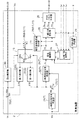
本発明の第一の実施形態について図面に基づいて説明する。図1に示すように、本実施形態においては、電動機駆動装置1が、三相交流により動作する交流電動機としての埋込磁石構造の同期電動機4(IPMSM、以下単に「電動機4」という。)を駆動する装置として構成されている場合を例として説明する。この電動機4は、必要に応じて発電機としても動作するように構成されている。この電動機4は、例えば、電動車両やハイブリッド車両等の駆動力源として用いられる。電動機駆動装置1は、直流電源3からの電源電圧Vbを変換して所望のシステム電圧Vdcを生成するコンバータ5と、当該システム電圧Vdcを交流に変換して電動機4に供給するインバータ6とを有して構成されている。そして、本実施形態では、図2に示すように、制御装置2は、ベクトル制御の手法を用いて電動機駆動装置1の制御を行う。この際、制御装置2は、電動機4の目標トルクTM及び回転速度ωに基づいて決定される交流電圧指令値Vd、Vqと、コンバータ5による変換後の実際のシステム電圧Vdcと、に基づいて、コンバータ5により生成するシステム電圧Vdcの指令値であるシステム電圧指令値Vdctを決定する点に特徴を有している。以下、本実施形態に係る電動機駆動装置1及びその制御装置2について詳細に説明する。
1. First Embodiment A first embodiment of the present invention will be described with reference to the drawings. As shown in FIG. 1, in the present embodiment, the
1−1.電動機駆動装置の構成
まず、本実施形態に係る電動機駆動装置1の構成について図1に基づいて説明する。この電動機駆動装置1は、コンバータ5とインバータ6とを備えている。また、電動機駆動装置1は、直流電源3と、直流電源3からの電源電圧Vbを平滑化する第一平滑コンデンサC1と、コンバータ5による昇圧後のシステム電圧Vdcを平滑化する第二平滑コンデンサC2と、を備えている。直流電源3としては、例えば、ニッケル水素二次電池やリチウムイオン二次電池等の各種二次電池、キャパシタ、或いはこれらの組合せ等が用いられる。直流電源3の電圧である電源電圧Vbは、電源電圧センサ41により検出されて制御装置2へ出力される。
1-1. Configuration of Electric Motor Drive Device First, the configuration of an electric
コンバータ5は、直流電源3からの電源電圧Vbを変換して所望値の直流のシステム電圧Vdcを生成するDC−DCコンバータであり、本発明における電圧変換部に相当する。本実施形態では、このコンバータ5は、電源電圧Vbを昇圧して所望のシステム電圧Vdcを生成する昇圧コンバータとして機能する。なお、電動機4が発電機として機能する際には、インバータ6からのシステム電圧Vdcを降圧して直流電源3に供給し、当該直流電源3を充電する。コンバータ5は、リアクトルL1と、電圧変換用スイッチング素子E1、E2と、ダイオードD1、D2と、を備えている。ここでは、コンバータ5は、電圧変換用スイッチング素子として、直列に接続された一対の上アーム素子E1及び下アーム素子E2を備えている。これらの電圧変換用スイッチング素子E1、E2として、本例では、IGBT(絶縁ゲートバイポーラトランジスタ)を用いる。上アーム素子E1のエミッタと下アーム素子E2のコレクタとが、リアクトルL1を介して直流電源3の正極端子に接続されている。また、上アーム素子E1のコレクタは、コンバータ5による昇圧後の電圧が供給されるシステム電圧線51に接続され、下アーム素子E2のエミッタは、直流電源3の負極端子につながる負極線52に接続されている。また、各電圧変換用スイッチング素子E1、E2には、それぞれフリーホイールダイオードとして機能するダイオードD1、D2が並列接続されている。なお、電圧変換用スイッチング素子E1、E2としては、IGBTの他に、バイポーラ型、電界効果型、MOS型など種々の構造のパワートランジスタを用いることができる。
The
電圧変換用スイッチング素子E1、E2のそれぞれは、制御装置2から出力されるスイッチング制御信号S1、S2に従ってオンオフ動作を行う。本実施形態では、スイッチング制御信号S1、S2は、各スイッチング素子E1、E2のゲートを駆動するゲート駆動信号である。これにより、コンバータ5は、昇圧動作時には、直流電源3から供給された電源電圧Vbを所望のシステム電圧Vdcまで昇圧し、システム電圧線51及びインバータ6に供給する。また、コンバータ5は、降圧動作時には、インバータ6から供給されたシステム電圧Vdcを降圧して直流電源3に供給する。コンバータ5により生成されるシステム電圧Vdcは、システム電圧センサ42により検出されて制御装置2へ出力される。なお、後述するように、昇圧指令値ΔVb(図2参照)がゼロであってコンバータ5により昇圧を行わない場合には、システム電圧Vdcは電源電圧Vbと等しくなる。
Each of the voltage conversion switching elements E1 and E2 performs an on / off operation in accordance with the switching control signals S1 and S2 output from the
インバータ6は、直流のシステム電圧Vdcを交流電圧に変換して電動機4に供給するための装置であり、本発明における直流交流変換部に相当する。インバータ6は、複数組のスイッチング素子E3〜E8と、ダイオードD3〜D8と、を備えている。ここでは、インバータ6は、電動機4の各相(U相、V相、W相の3相)のそれぞれについて一対のスイッチング素子、具体的には、U相用上アーム素子E3及びU相用下アーム素子E4、V相用上アーム素子E5及びV相用下アーム素子E6、並びにW相用上アーム素子E7及びW相用下アーム素子E8を備えている。これらのスイッチング素子E3〜E8として、本例では、IGBT(絶縁ゲートバイポーラトランジスタ)を用いる。各相用の上アーム素子E3、E5、E7のエミッタと下アーム素子E4、E6、E8のコレクタとが、電動機4の各相のコイルにそれぞれ接続されている。また、各相用の上アーム素子E3、E5、E7のコレクタはシステム電圧線51に接続され、各相用の下アーム素子E4、E6、E8のエミッタは負極線52に接続されている。また、各スイッチング素子E3〜E8には、それぞれフリーホイールダイオードとして機能するダイオードD3〜D8が並列接続されている。なお、スイッチング素子E3〜E8としては、IGBTの他に、バイポーラ型、電界効果型、MOS型など種々の構造のパワートランジスタを用いることができる。
The
スイッチング素子E3〜E8のそれぞれは、制御装置2から出力されるスイッチング制御信号S3〜S8に従ってオンオフ動作を行う。これにより、インバータ6は、システム電圧Vdcを交流電圧に変換して電動機4に供給し、目標トルクTMに応じたトルクを電動機4に出力させる。この際、各スイッチング素子E3〜E8は、スイッチング制御信号S3〜S8に従って、後述するPWM(パルス幅変調)制御又は矩形波制御に従ったスイッチング動作を行う。本実施形態では、スイッチング制御信号S3〜S8は、各スイッチング素子E3〜E8のゲートを駆動するゲート駆動信号である。一方、電動機4が発電機として機能する際には、発電された交流電圧を直流電圧に変換してシステム電圧線51及びコンバータ5に供給する。インバータ6と電動機4の各相のコイルとの間を流れる各相電流、具体的には、U相電流Iur、V相電流Ivr、及びW相電流Iwrは、電流センサ43により検出されて制御装置2へ出力される。
Each of the switching elements E3 to E8 performs an on / off operation according to the switching control signals S3 to S8 output from the
また、電動機4のロータの各時点での磁極位置θは、回転センサ44により検出されて制御装置2へ出力される。回転センサ44は、例えばレゾルバ等により構成される。ここで、磁極位置θは、電気角上でのロータの回転角度を表している。電動機4の目標トルクTMは、図示しない車両制御装置等の他の制御装置等からの要求信号として制御装置2に入力される。
Further, the magnetic pole position θ at each time point of the rotor of the electric motor 4 is detected by the
1−2.制御装置の構成
次に、図1に示される制御装置2の機能について、図2〜図5を用いて詳細に説明する。以下に説明する制御装置2の各機能部は、マイクロコンピュータ等の論理回路を中核部材として、入力されたデータに対して種々の処理を行うためのハードウエア又はソフトウエア(プログラム)或いはその両方により構成されている。上記のとおり、制御装置2には、目標トルクTM及び磁極位置θが入力される。そこで、制御装置2は、これらの目標トルクTM、磁極位置θ、及び磁極位置θから導出される電動機4の回転速度ωに応じて電動機4を駆動するためのスイッチング制御信号S3〜S8を生成して出力し、インバータ6を駆動する。この際、制御装置2は、PWM制御及び最大トルク制御と、矩形波制御及び弱め界磁制御と、を切り替えてインバータ6を駆動する。また、制御装置2には、直流電源3の電源電圧Vb及びコンバータ5により生成されたシステム電圧Vdcが入力される。そこで、制御装置2は、目標トルクTM及び回転速度ωに基づいて定まる交流電圧指令値Vd、Vqと現在のシステム電圧Vdcとに基づいて、システム電圧Vdcの指令値であるシステム電圧指令値Vdctを決定する。そして、制御装置2は、決定されたシステム電圧Vdcを生成するためのスイッチング制御信号S1、S2を生成して出力し、コンバータ5を駆動する。
1-2. Configuration of Control Device Next, functions of the
制御装置2は、インバータ6における直流−交流変換に際して、PWM制御と矩形波制御とを切り替えて実行する。本実施形態では、PWM制御には、正弦波PWM制御と過変調PWM制御の2つの制御方式が含まれる。正弦波PWM制御では、インバータ6の各スイッチング素子E3〜E8のオンオフを、正弦波状の電圧指令値Vu、Vv、Vwと搬送波との比較に基づいて制御する。具体的には、U、V、Wの各相のインバータ6の出力電圧波形が、上アーム素子E3、E5、E7がオン状態となるハイレベル期間と、下アーム素子E4、E6、E8がオン状態となるローレベル期間とにより構成されるパルスの集合で構成されると共に、その基本波成分が一定期間で正弦波となるように、各パルスのデューティ比を制御する。システム電圧Vdcに対するインバータ6の出力電圧波形の基本波成分の実効値の比率を変調率m(後述する式(7)参照)とすると、正弦波PWM制御では、変調率mは0〜0.61の範囲で変化させることができる。
The
過変調PWM制御では、正弦波PWM制御に比べて各パルスのデューティ比を基本波成分の山側で大きく谷側で小さくすることにより、インバータ6の出力電圧波形の基本波成分の波形を歪ませて振幅が正弦波PWM制御よりも大きくなるように制御する。過変調PWM制御では、変調率mは0.61〜0.78の範囲で変化させることができる。この過変調PWM制御において変調率mを最大の0.78まで高めた状態が矩形波制御となる。矩形波制御では、U、V、Wの各相のインバータ6の出力電圧波形が、1周期につき前記ハイレベル期間と前記ローレベル期間とが1回ずつ交互に表れるとともにこれらのハイレベル期間とローレベル期間との比が1:1の矩形波となるように制御する。これにより、矩形波制御は、インバータ6に矩形波状電圧を出力させる。矩形波制御では、変調率mは0.78で固定される。
In the overmodulation PWM control, the waveform of the fundamental wave component of the output voltage waveform of the
ところで、電動機4は、回転速度ωが高くなるに従って誘起電圧が高くなり、電動機4を駆動するために必要となる交流電圧(以下「必要電圧」という。)も高くなる。そして、この必要電圧が、そのときのシステム電圧Vdcを変換してインバータ6から出力し得る最大の交流電圧(以下「最大出力電圧」という。)を超えると、コイルに必要な電流を流すことができなり、電動機4を適切に制御することができない。そこで、本実施形態では、電動機4の必要電圧に応じてPWM制御(正弦波PWM制御又は過変調PWM制御)における変調率mを0〜0.78の範囲で変化させつつ、その範囲内での最大出力電圧より電動機4の必要電圧が低い状態ではPWM制御と共に最大トルク制御を行う。そして、電動機4の必要電圧が、PWM制御の最大変調率(m=0.78)での最大出力電圧に達すると矩形波制御と共に弱め界磁制御を行う。ここで、最大トルク制御は、同一電流に対して電動機4の出力トルクが最大となるように電流位相を調節する制御である。また、弱め界磁制御は、電動機4の界磁磁束を弱める方向の磁束がコイルから発生するように電流位相を調節する(電流位相を最大トルク制御よりも進める)制御である。なお、上記の必要電圧及び最大出力電圧は、共に交流電圧の実効値として互いに比較することができる。
Incidentally, the induced voltage of the electric motor 4 increases as the rotational speed ω increases, and the AC voltage (hereinafter referred to as “necessary voltage”) required to drive the electric motor 4 also increases. When this required voltage exceeds the maximum AC voltage (hereinafter referred to as “maximum output voltage”) that can be converted from the system voltage Vdc at that time and output from the
図3は、回転速度ωと目標トルクTMとにより規定される電動機4の動作可能領域の中における、PWM制御及び最大トルク制御が実行される領域A1と矩形波制御及び弱め界磁制御が実行される領域A2とを示した図である。なお、この図3は、システム電圧Vdcの昇圧を考慮しない図となっている。上記のとおり、電動機4の回転速度ωが高くなるに従って誘起電圧が高くなるため、電動機4の必要電圧もこれに応じて高くなる。従って、制御装置2に入力された目標トルクTMとそのときの電動機4の回転速度ωとにより定まる動作点が、比較的低回転の領域A1内に位置する場合にはPWM制御及び最大トルク制御が実行され、当該動作点が、比較的高回転の領域A2内に位置する場合には矩形波制御及び弱め界磁制御が実行される。領域A1と領域A2との境界は、最大トルク制御中における電動機4の必要電圧が、PWM制御の最大変調率(すなわち矩形波制御となる変調率m=0.78)での最大出力電圧に一致する回転速度ω及びトルクにより定まる。
FIG. 3 shows a region A1 in which PWM control and maximum torque control are executed, and a region in which rectangular wave control and field weakening control are executed, in the operable region of the motor 4 defined by the rotational speed ω and the target torque TM. It is the figure which showed A2. FIG. 3 is a diagram that does not consider boosting of the system voltage Vdc. As described above, since the induced voltage increases as the rotational speed ω of the electric motor 4 increases, the required voltage of the electric motor 4 also increases accordingly. Therefore, when the operating point determined by the target torque TM input to the
図2に示すように、d軸電流指令値導出部21には、目標トルクTMが入力される。d軸電流指令値導出部21は、入力された目標トルクTMに基づいて基本d軸電流指令値Idbを導出する。ここで、基本d軸電流指令値Idbは、最大トルク制御を行う場合におけるd軸電流の指令値に相当する。本実施形態では、d軸電流指令値導出部21は、図4に示す基本d軸電流指令値テーブルを用いて、目標トルクTMの値に応じた基本d軸電流指令値Idbを導出する。図示の例では、目標トルクTMとして「tm3」の値が入力され、これに応じて、d軸電流指令値導出部21は、基本d軸電流指令値Idbとして「Id1」を導出する。このように導出された基本d軸電流指令値Idbは、第一減算器23へ入力される。第一減算器23には、更に、後述する第一積分器31により導出された弱め界磁電流指令値ΔIdが入力される。第一減算器23は、下記の式(1)に示すように、基本d軸電流指令値Idbから弱め界磁電流指令値ΔIdを減算し、最終的なd軸電流指令値Idを導出する。
Id=Idb−ΔId・・・(1)
As shown in FIG. 2, the target torque TM is input to the d-axis current command
Id = Idb−ΔId (1)
q軸電流指令値導出部22には、目標トルクTM及び弱め界磁電流指令値ΔIdが入力される。q軸電流指令値導出部22は、入力された目標トルクTMと弱め界磁電流指令値ΔIdとに基づいてq軸電流指令値Iqを導出する。本実施形態では、q軸電流指令値導出部22は、図5に示すq軸電流指令値テーブルを用いて、目標トルクTM及び弱め界磁電流指令値ΔIdの値に応じたq軸電流指令値Iqを導出する。図5において、細い実線は、tm1〜tm5の各トルクを出力するためのd軸電流及びq軸電流の値を示す等トルク線61であり、太い実線は最大トルク制御を行うためのd軸電流及びq軸電流の値を示す最大トルク制御線62である。図示の例では、目標トルクTMとして「tm3」の値が入力されると共に、弱め界磁電流指令値ΔIdとして「ΔId1」が入力されている。これに応じて、q軸電流指令値導出部22は、まず、目標トルクTM=tm3の等トルク線61と最大トルク制御線62との交点のq軸電流の値である「Iq1」を基本q軸電流指令値として導出する。ここで、基本q軸電流指令値は、最大トルク制御を行う場合におけるd軸電流の指令値に相当する。よって、弱め界磁電流指令値ΔIdがゼロである場合(ΔId=0)には、この基本q軸電流指令値が最終的なq軸電流指令値Iqとなる。本例では、弱め界磁電流指令値ΔIdとして「ΔId1」が入力されているので、目標トルクTM=tm3の等トルク線61に沿ってd軸の負方向にΔId1だけ移動した点のq軸電流の値である「Iq2」をq軸電流指令値Iqとして導出する。なお、図5のq軸電流指令値テーブルにより求められる基本q軸電流指令値(Iq1)に対応するd軸電流の値(Id1)は、図4に示す基本d軸電流指令値テーブルを用いて求められる基本d軸電流指令値Idbの値と一致し、このd軸電流の値(Id1)から弱め界磁電流指令値ΔId(=ΔId1)を減算して求められるd軸電流の値(Id2)は、第一減算器23により導出される最終的なd軸電流指令値Id(=Idb−ΔId)と一致する。よって、d軸電流指令値Idをこの図5に示すテーブルにより求めることも可能である。
The target torque TM and the field weakening current command value ΔId are input to the q-axis current command
電流制御部24には、上記のように導出されたd軸電流指令値Id及びq軸電流指令値Iqが入力される。更に、電流制御部24には、三相二相変換部27から実d軸電流Idr及び実q軸電流Iqrが入力され、回転速度導出部28から電動機4の回転速度ωが入力される。実d軸電流Idr及び実q軸電流Iqrは、電流センサ43(図1参照)により検出されたU相電流Iur、V相電流Ivr、及びW相電流Iwrと回転センサ44(図1参照)により検出された磁極位置θとに基づいて、三相二相変換部27により三相二相変換を行って導出される。また、電動機4の回転速度ωは、回転センサ44(図1参照)により検出された磁極位置θに基づいて回転速度導出部28により導出される。
The d-axis current command value Id and the q-axis current command value Iq derived as described above are input to the
電流制御部24は、d軸電流指令値Idと実d軸電流Idrとの偏差であるd軸電流偏差δId、及びq軸電流指令値Iqと実q軸電流Iqrとの偏差であるq軸電流偏差δIqを導出する。そして、電流制御部24は、d軸電流偏差δIdに基づいて比例積分制御演算(PI制御演算)を行って電圧降下のd軸成分であるd軸電圧降下Vzdを導出すると共に、q軸電流偏差δIqに基づいて比例積分制御演算を行って電圧降下のq軸成分であるq軸電圧降下Vzqを導出する。
The
そして、電流制御部24は、下記の式(2)に示すように、d軸電圧降下Vzdからq軸電機子反作用Eqを減算してd軸電圧指令値Vdを導出する。
Vd=Vzd−Eq
=Vzd−ω・Lq・Iqr・・・(2)
この式(2)に示されるように、q軸電機子反作用Eqは、電動機4の回転速度ω、実q軸電流Iqr、及びq軸インダクタンスLqに基づいて導出される。
Then, the
Vd = Vzd-Eq
= Vzd-ω · Lq · Iqr (2)
As shown in this equation (2), the q-axis armature reaction Eq is derived based on the rotational speed ω of the electric motor 4, the actual q-axis current Iqr, and the q-axis inductance Lq.
更に、電流制御部24は、下記の式(3)に示すように、q軸電圧降下Vzqにd軸電機子反作用Ed及び永久磁石の電機子鎖交磁束による誘起電圧Emを加算してq軸電圧指令値Vqを導出する。
Vq=Vzq+Ed+Em
=Vzq+ω・Ld・Idr+ω・MIf・・・(3)
この式(3)に示されるように、d軸電機子反作用Edは、電動機4の回転速度ω、実d軸電流Idr、及びd軸インダクタンスLdに基づいて導出される。また、誘起電圧Emは、永久磁石の電機子鎖交磁束の実効値により定まる誘起電圧定数MIf及び電動機4の回転速度ωに基づいて導出される。
Further, the
Vq = Vzq + Ed + Em
= Vzq + ω · Ld · Idr + ω · Mif (3)
As shown in this equation (3), the d-axis armature reaction Ed is derived based on the rotational speed ω of the electric motor 4, the actual d-axis current Idr, and the d-axis inductance Ld. The induced voltage Em is derived based on the induced voltage constant MIf determined by the effective value of the armature linkage flux of the permanent magnet and the rotational speed ω of the motor 4.
本実施形態においては、d軸電圧指令値Vd及びq軸電圧指令値Vqを、インバータ6から電動機4に供給する交流電圧の指令値である交流電圧指令値とする。従って、上述したd軸電流指令値導出部21、q軸電流指令値導出部22、及び電流制御部24により、電動機4の目標トルクTM及び回転速度ωに基づいて交流電圧指令値Vd、Vqを決定する交流電圧指令決定部7が構成されている。
In the present embodiment, the d-axis voltage command value Vd and the q-axis voltage command value Vq are set as AC voltage command values that are command values for the AC voltage supplied from the
二相三相変換部25には、d軸電圧指令値Vd及びq軸電圧指令値Vqが入力される。また、二相三相変換部25には、回転センサ44(図1参照)により検出された磁極位置θも入力される。二相三相変換部25は、磁極位置θを用いて二相三相変換を行い、d軸電圧指令値Vd及びq軸電圧指令値Vqを、U相電圧指令値Vu、V相電圧指令値Vv、及びW相電圧指令値Vwに変換して導出する。
The d-axis voltage command value Vd and the q-axis voltage command value Vq are input to the two-phase / three-
PWMパルス生成部26には、U相電圧指令値Vu、V相電圧指令値Vv、及びW相電圧指令値Vwが入力される。PWMパルス生成部26は、正弦波状の各相の電圧指令値Vu、Vv、Vwと搬送波との比較に基づいて、図1に示すインバータ6の各スイッチング素子E3〜E8を制御するスイッチング制御信号S3〜S8を生成する。そして、インバータ6の各スイッチング素子E3〜E8がスイッチング制御信号S3〜S8に従ってオンオフ動作を行うことにより、PWM制御(正弦波PWM制御又は過変調PWM制御)又は矩形波制御が行われる。本実施形態では、搬送波の振幅を、正弦波PWM制御における上限の変調率m(=0.61)に相当する各相の電圧指令値Vu、Vv、Vwの振幅と同じ値に固定している。これにより、PWMパルス生成部26は、入力された各相の電圧指令値Vu、Vv、Vwが、正弦波PWM制御における上限の変調率m(=0.61)を超える変調率m(=0.61〜0.78)に相当する振幅である場合には、インバータ6の出力電圧波形が基本的にPWMパルスとなると共に電圧指令値Vu、Vv、Vwが搬送波の振幅を超える部分において連続的にハイレベル又はローレベルとなる過変調PWM制御を実行するためのスイッチング制御信号S3〜S8を生成する。更に、PWMパルス生成部26は、入力された各相の電圧指令値Vu、Vv、Vwが、過変調PWM制御における上限の変調率m(=0.78)に相当する振幅である場合には、インバータ6の出力電圧波形が1周期につきハイレベル期間とローレベル期間とが1回ずつ交互に表れる矩形波となる矩形波制御を実行するためのスイッチング制御信号S3〜S8を生成する。
The
電圧指令換算値導出部29には、d軸電圧指令値Vd及びq軸電圧指令値Vqが入力される。電圧指令換算値導出部29は、d軸電圧指令値Vd及びq軸電圧指令値Vqに基づいて電圧指令換算値Vaを、下記の式(4)に従って導出する。
Va=√(Vd2+Vq2)/0.78・・・(4)
ここで、√(Vd2+Vq2)は、3相の線間電圧実効値に相当する。従って、本実施形態では、電圧指令換算値Vaは、3相の線間電圧実効値を理論上の最大変調率(m=0.78)で除算した値として導出される。この電圧指令換算値Vaは、交流電圧指令値Vd、Vqをシステム電圧Vdcと比較可能とするための換算値であり、交流電圧指令値Vd、Vqを出力するために必要とされる直流電圧(システム電圧Vdc)を表している。より詳しくは、電圧指令換算値Vaは、交流電圧指令値Vd、Vqに従った交流電圧を出力するためにインバータ6に入力されることが必要とされるシステム電圧Vdcを表している。
The d-axis voltage command value Vd and the q-axis voltage command value Vq are input to the voltage command converted value deriving unit 29. The voltage command converted value deriving unit 29 derives the voltage command converted value Va according to the following equation (4) based on the d-axis voltage command value Vd and the q-axis voltage command value Vq.
Va = √ (Vd 2 + Vq 2 ) /0.78 (4)
Here, √ (Vd 2 + Vq 2 ) corresponds to a three-phase line voltage effective value. Therefore, in the present embodiment, the voltage command converted value Va is derived as a value obtained by dividing the effective value of the three-phase line voltage by the theoretical maximum modulation factor (m = 0.78). This voltage command conversion value Va is a conversion value for making the AC voltage command values Vd and Vq comparable to the system voltage Vdc, and is a DC voltage (needed to output the AC voltage command values Vd and Vq). System voltage Vdc). More specifically, voltage command converted value Va represents system voltage Vdc that needs to be input to
第二減算器30には、電圧指令換算値Va、及びシステム電圧センサ42により検出されたシステム電圧Vdcの値が入力される。第二減算器30は、下記の式(5)に示すように、電圧指令換算値Vaからシステム電圧Vdcの値を減算した電圧偏差ΔVを導出する。
ΔV=Va−Vdc・・・(5)
本実施形態においては、この電圧偏差ΔVが、システム電圧Vdcに対する交流電圧指令値Vd、Vqの大きさを表す電圧指標に相当する。よって本実施形態では、電圧指令換算値導出部29及び第二減算器30により、電圧指標導出部11が構成されている。ここでは、電圧偏差ΔVは、交流電圧指令値Vd、Vqがそのときのシステム電圧Vdcによって出力し得る最大の交流電圧の値を超えている程度を表す。従って、電圧偏差ΔVは、実質的にはシステム電圧Vdcの不足の程度を表す電圧不足指標として機能する。
The second subtracter 30 receives the voltage command converted value Va and the value of the system voltage Vdc detected by the
ΔV = Va−Vdc (5)
In the present embodiment, the voltage deviation ΔV corresponds to a voltage index representing the magnitudes of the AC voltage command values Vd and Vq with respect to the system voltage Vdc. Therefore, in this embodiment, the voltage index conversion value deriving unit 29 and the second subtractor 30 constitute the voltage
本実施形態では、処理切替部10には、電圧偏差ΔV、弱め界磁電流指令値ΔId、及びシステム電圧指令値Vdctが入力される。処理切替部10は、これらの値に基づいて、システム電圧指令決定部9によりシステム電圧指令値Vdctを決定するシステム電圧決定処理と、弱め界磁指令値決定部8により弱め界磁電流指令値ΔIdを決定する弱め界磁指令値決定処理との実行状態を切り替える。本実施形態では、処理切替部10は、弱め界磁指令値決定処理を実行する第一状態M1、システム電圧決定処理を実行する第二状態M2、及びこれらの双方を実行しない第三状態M3を切り替える。そして、処理切替部10は、第一状態M1では電圧偏差ΔVを第一積分器31へ入力し、第二状態M2では電圧偏差ΔVを第二積分器32へ入力し、第三状態M3では電圧偏差ΔVを第一積分器31及び第二積分器32のいずれにも入力しない。処理切替部10は、電圧偏差ΔV、弱め界磁電流指令値ΔId、及びシステム電圧指令値Vdctのそれぞれについて予め規定されたしきい値と比較した結果に基づいて、3つの状態M1、M2、M3の切り替えを行う。なお、この処理切替部10による切り替え動作については、後で図6〜図8を用いて詳細に説明するため、ここでは詳しく説明しない。
In the present embodiment, a voltage deviation ΔV, a field weakening current command value ΔId, and a system voltage command value Vdct are input to the
処理切替部10が第一状態M1にあるときに、第一積分器31には電圧偏差ΔVが入力される。第一積分器31は、この電圧偏差ΔVを所定のゲインを用いて積分し、当該積分値を弱め界磁電流指令値ΔIdとして導出する。ここでは、第一積分器31は、自己保持回路等による自己保持機能を備えるものとしている。そして、第一積分器31は、処理切替部10が第二状態M2となったときには、処理切替部10が第一状態M1にあったときの最終の弱め界磁電流指令値ΔIdを保持し、当該値を出力し続けるように構成されている。また、第一積分器31は、処理切替部10が第三状態M3となったときには自己保持機能を解除するように構成されている。本実施形態では、この弱め界磁電流指令値ΔIdが、電動機4の界磁磁束を弱める弱め界磁制御を行う際の弱め界磁の程度を表す弱め界磁指令値に相当する。また、電圧指令換算値導出部29、第二減算器30、及び第一積分器31により、交流電圧指令値Vd、Vqとシステム電圧Vdcとに基づいて弱め界磁電流指令値ΔIdが決定される。よって、本実施形態では、電圧指令換算値導出部29、第二減算器30、及び第一積分器31により、弱め界磁指令値決定部8が構成されている。上記のとおり、本実施形態では、矩形波制御と共に弱め界磁制御を行い、PWM制御と共に最大トルク制御を行う。従って、制御装置2は、弱め界磁電流指令値ΔIdがゼロの状態ではインバータ6にPWM制御を行わせ、弱め界磁電流指令値ΔIdがゼロ以外の状態ではインバータ6に矩形波制御を行わせる構成となっている。
When the
処理切替部10が第二状態M2にあるときに、第二積分器32には電圧偏差ΔVが入力される。第二積分器32は、この電圧偏差ΔVを所定のゲインを用いて積分し、当該積分値を昇圧指令値ΔVbとして導出する。ここでは、第二積分器32は、自己保持回路等による自己保持機能を備えるものとしている。そして、第二積分器32は、処理切替部10が第一状態M1となったときには、処理切替部10が第二状態M2にあったときの最終の昇圧指令値ΔVbを保持し、当該値を出力し続けるように構成されている。また、第二積分器32は、処理切替部10が第三状態M3となったときには自己保持機能を解除するように構成されている。この昇圧指令値ΔVbは、電流制御部24で導出された交流電圧指令値Vd、Vqに従った交流電圧を出力するためにインバータ6に入力されることが必要とされるシステム電圧Vdcを得るために、電源電圧Vbに対して昇圧する必要がある電圧値に相当する。
When the
加算器33には、電源電圧センサ41により検出された電源電圧Vb及び昇圧指令値ΔVbが入力される。加算器33は、下記の式(6)に示すように、電源電圧Vbに昇圧指令値ΔVbを加算したシステム電圧指令値Vdctを導出する。
Vdct=Vb+ΔVb・・・(6)
このシステム電圧指令値Vdctが、コンバータ5により生成するシステム電圧Vdcの指令値となる。上記のとおり、電圧指令換算値導出部29、第二減算器30、第二積分器32、及び加算器33により、交流電圧指令値Vd、Vqとシステム電圧Vdcとに基づいてシステム電圧指令値Vdctが決定される。よって、本実施形態では、電圧指令換算値導出部29、第二減算器30、第二積分器32、及び加算器33により、システム電圧指令決定部9が構成されている。上記のとおり、このシステム電圧指令決定部9は、電圧指標として電圧指令換算値導出部29及び第二減算器30により導出される電圧偏差ΔVに基づいて、より具体的には、当該電圧偏差ΔVを第二積分器32により積分して導出される積分値である昇圧指令値ΔVbと電源電圧Vbとに基づいて、システム電圧指令値Vdctを決定している。
The
Vdct = Vb + ΔVb (6)
This system voltage command value Vdct becomes the command value of system voltage Vdc generated by
昇圧制御部34には、システム電圧指令値Vdctが入力される。昇圧制御部34は、システム電圧指令値Vdctに応じて、コンバータ5の電圧変換用スイッチング素子E1、E2を制御するスイッチング制御信号S1、S2を生成する。そして、コンバータ5の電圧変換用スイッチング素子E1、E2がスイッチング制御信号S1、S2に従ってオンオフ動作を行うことにより、電源電圧Vbが昇圧される。具体的には、コンバータ5は、制御装置2からのスイッチング制御信号S1、S2に応答して、下アーム素子E2のみが所定期間オンする状態と、上アーム素子E1及び下アーム素子E2の双方が所定期間オフする状態とを交互に繰り返す動作を行い、電源電圧Vbを昇圧する。この際の昇圧比は下アーム素子E2のオン期間のデューティ比に応じたものとなる。すなわち、下アーム素子E2のオンデューティを大きくするに従ってリアクトルL1における電力蓄積が大きくなるため、コンバータ5から出力されるシステム電圧Vdcを高くすることができる。
System voltage command value Vdct is input to boost
1−3.処理切替部の動作
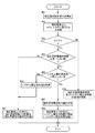
次に、処理切替部10の切り替え動作及びそれに伴う制御装置2の各部の動作について、図6〜図8を用いて詳細に説明する。図6は、処理切替部10による切り替え動作に伴う制御装置2の各部の動作の流れを示すフローチャートである。
1-3. Operation of Process Switching Unit Next, the switching operation of the
図6に示すように、制御装置2は、まず、電圧指令換算値導出部29により電圧指令換算値Vaを導出する(ステップ#01)。次に、第二減算器30により、電圧指令換算値Vaからシステム電圧Vdcの値を減算した電圧偏差ΔV(=Va−Vdc)を導出する(ステップ#02)。そして、処理切替部10により、ステップ#02で導出された電圧偏差ΔVがゼロより大きいか(ΔV>0)否かを判定する(ステップ#03)。電圧偏差ΔVがゼロより大きい場合には(ステップ#03:Yes)、システム電圧Vdcが交流電圧指令値Vd、Vqに対して不足しているということになる。そこで、処理切替部10は、次に、そのときの弱め界磁電流指令値ΔIdが所定の第一しきい値ΔIds以上であるか(ΔId≧ΔIds)否かを判定する(ステップ#04)。弱め界磁電流指令値ΔIdが第一しきい値ΔIds未満である場合には(ステップ#04:No)、処理切替部10は、電圧偏差ΔVを第一積分器31に入力する第一状態M1となり、弱め界磁指令値決定処理を実行状態とする。これにより、第一積分器31が電圧偏差ΔVを積分して弱め界磁電流指令値ΔIdを導出する(ステップ#05)。この場合、制御装置2は、インバータ6に弱め界磁制御及び矩形波制御を行わせ、コンバータ5には昇圧制御を行わせず電源電圧Vbをそのままシステム電圧Vdcとして出力させる。
As shown in FIG. 6, the
弱め界磁電流指令値ΔIdが第一しきい値ΔIds以上である場合には(ステップ#04:Yes)、次に、処理切替部10により、システム電圧指令値Vdctが第二しきい値Vdcmax未満であるか(Vdct<Vdcmax)否かを判定する(ステップ#06)。システム電圧指令値Vdctが第二しきい値Vdcmax未満である場合には(ステップ#06:Yes)、第一積分器31によりそのときの弱め界磁電流指令値ΔIdを保持させる(ステップ#07)。そして、処理切替部10は、電圧偏差ΔVを第二積分器32に入力する第二状態M2となり、システム電圧決定処理を実行状態とする。これにより、第二積分器32が電圧偏差ΔVを積分してシステム電圧指令値Vdctを導出する(ステップ#08)。この場合、制御装置2は、ステップ#07で保持された一定の弱め界磁電流指令値ΔIdに従ってインバータ6に弱め界磁制御を行わせるとともに矩形波制御を行わせ、コンバータ5には昇圧制御を行わせて電源電圧Vbに対して昇圧したシステム電圧Vdcを出力させる。
If field weakening current command value ΔId is greater than or equal to first threshold value ΔIds (step # 04: Yes), then system voltage command value Vdct is less than second threshold value Vdcmax by
システム電圧指令値Vdctが第二しきい値Vdcmax以上である場合には(ステップ#06:No)、第二積分器32によりそのときの昇圧指令値ΔVbを保持させ、それによってそのときのシステム電圧指令値Vdctを保持させる(ステップ#09)。そして、処理切替部10は、電圧偏差ΔVを第一積分器31に入力する第一状態M1となり、第一積分器31が電圧偏差ΔVを積分して弱め界磁電流指令値ΔIdを導出する(ステップ#05)。この場合、制御装置2は、ステップ#09で保持された一定のシステム電圧指令値Vdctに従ってコンバータ5に昇圧制御を行わせて電源電圧Vbに対して昇圧したシステム電圧を出力させるとともに、弱め界磁電流指令値ΔIdを調整しつつインバータ6に弱め界磁制御及び矩形波制御を行わせる。
When the system voltage command value Vdct is equal to or greater than the second threshold value Vdcmax (step # 06: No), the
一方、電圧偏差ΔVがゼロ以下である場合には(ステップ#03:No)、処理切替部10は、電圧偏差ΔVを第一積分器31及び第二積分器32のいずれにも入力しない第三状態M3となる。よって、本実施形態では、このゼロが、電圧指標としての電圧偏差ΔVについて予め定められたしきい値であり、このしきい値は、弱め界磁指令値決定処理及びシステム電圧決定処理の少なくとも一方を行うか否かを決定するための処理実行しきい値として機能する。そして、ステップ#07による弱め界磁電流指令値ΔIdの保持又はステップ#09によるシステム電圧指令値Vdctの保持が行われている場合には、当該保持を解除する(ステップ#10)。このときに弱め界磁制御が行われていた場合には、第一積分器31は弱め界磁電流指令値ΔIdを次第に減少させ、最終的には弱め界磁制御を終了する。また、このときに昇圧制御が行われていた場合には、第二積分器32は昇圧指令値ΔVbを次第に減少させ、最終的には昇圧制御を終了する。一方、このときに弱め界磁制御及び昇圧制御の双方が行われていなかった場合、すなわち、インバータ6に最大トルク制御及びPWM制御を行わせ、コンバータ5には昇圧制御を行わせず電源電圧Vbをそのままシステム電圧Vdcとして出力させていた場合には、制御装置2はその状態を維持する。
On the other hand, when the voltage deviation ΔV is equal to or less than zero (step # 03: No), the
上記のとおり、第一しきい値ΔIdsは、コンバータ5による昇圧を開始するための弱め界磁電流指令値ΔIdのしきい値である。ここで、弱め界磁制御に伴って矩形波制御を行うと、PWM制御を行う場合に比べてインバータ6の各スイッチング素子E3〜E8のスイッチング回数が大幅に減少するので、スイッチング損失を低減することができる。一方、弱め界磁制御を行うための弱め界磁電流を増大させると電動機4に入力する電流に対して得られるトルクが減少するため効率が低下する。そこで、第一しきい値ΔIdsは、弱め界磁制御に伴って矩形波制御を行うことによるスイッチング損失の低減に伴う効率向上が、弱め界磁電流の増大(弱め界磁の程度の増大)による効率低下を上回る範囲内に設定されると好適である。このようにすることにより、電動機駆動装置1の効率を高めることができる。一方、第二しきい値Vdcmaxは、コンバータ5により昇圧可能なシステム電圧指令値Vdctの上限に設定されると好適である。これにより、弱め界磁電流を増大させることなくシステム電圧Vdcを上昇させることで電動機4の動作可能領域を拡大することができる(図8参照)。そして、システム電圧指令値Vdctが昇圧上限の第二しきい値Vdcmaxに到達した後は、効率は低下するが、弱め界磁電流指令値ΔIdを増大させることにより、電動機4の動作可能領域を更に拡大することができる。
As described above, the first threshold value ΔIds is a threshold value of the field weakening current command value ΔId for starting the boosting by the
次に、図6に示すフローチャートに従って処理切替部10による切り替え動作を行った場合の制御装置2の動作の具体例について、図7及び図8を用いて説明する。図7において、(a)は目標トルクTMが時間に応じて変化する一例を示し、(b)はそのときの弱め界磁電流指令値ΔIdの変化を示し、(c)はそのときのシステム電圧指令値Vdctの変化を示している。図7(a)に示すように、本例では、目標トルクTMは、まず電動機4により出力可能な最大トルクTMmaxまで上昇した後は、基本的に各時点での電動機4の回転速度ωに応じて出力可能な最大トルクに沿って推移するものとする。なお、本例では、電動機4の回転速度ωは一定の加速度で時間の経過と共に増加していくものとする。また、図8において、(b)は図7(c)に対応する時間経過に伴って回転速度ωが上昇した際のシステム電圧指令値Vdctの変化を示しており、(a)はこのようなシステム電圧指令値Vdctの変化に応じた電動機4の動作可能領域の変化を示している。図8(a)において、実線で示す領域は電源電圧Vbを昇圧せずにそのままシステム電圧Vdcとして用いた場合の動作可能領域であり、二点鎖線で示す領域は電源電圧Vbを次第に昇圧した場合に変化する動作可能領域を示している。また、図8(a)中における複数の黒点は、図7(a)に対応する各時点での目標トルクTMの推移を示している。
Next, a specific example of the operation of the
図8(a)に示すように、本例では、時刻t1までは、目標トルクTM及び回転速度ωにより規定される電動機4の動作点が、当該動作点で必要される交流電圧指令値Vd、Vqを出力するために電源電圧Vbを昇圧する必要がなく、最大トルク制御及びPWM制御を実行可能な領域A1にある。この場合、電圧偏差ΔVはゼロ以下となる(ステップ#03:No)。従って、図7(b)及び(c)に示すように、時刻t1までは、弱め界磁電流指令値ΔIdがゼロ、システム電圧指令値Vdctが電源電圧Vbと同じ値(昇圧指令値ΔVbがゼロ)となっている。 As shown in FIG. 8A, in this example, until the time t1, the operating point of the electric motor 4 defined by the target torque TM and the rotational speed ω is the AC voltage command value Vd required at the operating point, There is no need to boost the power supply voltage Vb in order to output Vq, and it is in the region A1 where maximum torque control and PWM control can be performed. In this case, the voltage deviation ΔV is equal to or less than zero (step # 03: No). Therefore, as shown in FIGS. 7B and 7C, until time t1, field weakening current command value ΔId is zero and system voltage command value Vdct is the same value as power supply voltage Vb (step-up command value ΔVb is zero). ).
その後、時刻t1〜t2では、図8(a)に示すように、電動機4の動作点が弱め界磁制御及び矩形波制御を行う必要がある領域A2に入っている。この場合、電圧偏差ΔVはゼロより大きくなる(ステップ#03:Yes)。そこで、図7(b)に示すように、処理切替部10により弱め界磁指令値決定処理が実行状態とされ(ステップ#05)、制御装置2が弱め界磁制御及び矩形波制御を実行する。これにより、弱め界磁電流指令値ΔIdは、時刻t1〜t2における回転速度ωの上昇に伴ってゼロから第一しきい値ΔIdsまで次第に増加している。この際、弱め界磁電流指令値ΔIdが第一しきい値ΔIds以下の状態では(ステップ#04:No)、制御装置2は昇圧制御は行わず、システム電圧指令値Vdctは電源電圧Vbと同じ値のままとなる。従って、電動機4が出力可能なトルクは、回転速度ωの上昇に伴って次第に低下している。本例では、時刻t2において、弱め界磁電流指令値ΔIdが第一しきい値ΔIdsに到達する(ステップ#04:Yes)。
Thereafter, at time t1 to t2, as shown in FIG. 8A, the operating point of the electric motor 4 is in the region A2 where field weakening control and rectangular wave control need to be performed. In this case, the voltage deviation ΔV is greater than zero (step # 03: Yes). Therefore, as shown in FIG. 7B, the
そこで、時刻t2〜t3では、図7(c)及び図8(b)に示すように、処理切替部10によりシステム電圧決定処理が実行状態とされ(ステップ#08)、制御装置2が昇圧制御を実行する。これにより、システム電圧指令値Vdctは、時刻t2〜t3における回転速度ωの上昇に伴って電源電圧Vbと同じ値からシステム電圧指令値Vdctの上限に設定された第二しきい値Vdcmaxまで次第に増加している。このようにシステム電圧Vdcが上昇することにより、図8(a)に示すように、電動機4の動作可能領域は高回転側へ次第に拡大する。本例では、電動機4の回転速度ωの上昇に伴ってシステム電圧指令値Vdctが昇圧されることにより、回転速度ωの上昇中にも電動機4が出力可能なトルクが一定に維持されている。なお、昇圧制御中における電動機4の回転速度ωと出力可能なトルクとの関係は、昇圧速度と電動機4のロータの加速度との関係により変化する。そして、図7(b)に示すように、このような昇圧制御中は、処理切替部10により弱め界磁指令値決定処理が中止され、昇圧制御を開始したときの弱め界磁電流指令値ΔId(=ΔIds)が保持される(ステップ#07)。従って、制御装置2は、このような昇圧制御中も弱め界磁制御及び矩形波制御を実行する。本例では、時刻t3において、システム電圧指令値Vdctが第二しきい値Vdcmaxに到達する(ステップ#06:No)。
Therefore, at time t2 to t3, as shown in FIG. 7C and FIG. 8B, the
そこで、時刻t3以後は、図7(c)に示すように、処理切替部10によりシステム電圧決定処理が中止され、システム電圧指令値Vdctが上限の第二しきい値Vdcmaxに保持される(ステップ#09)。また、図7(b)に示すように、処理切替部10により弱め界磁指令値決定処理が再開される(ステップ#05)。これにより、弱め界磁電流指令値ΔIdは、時刻t3以後における回転速度ωの上昇に伴って第一しきい値ΔIdsから次第に増加している。従って、電動機4が出力可能なトルクは、回転速度ωの上昇に伴って次第に低下している。当然ながら、制御装置2は、この間も弱め界磁制御及び矩形波制御を実行する。
Therefore, after time t3, as shown in FIG. 7C, the system voltage determination process is stopped by the
以上より、本実施形態に係る構成によれば、電動機4の回転速度ωや目標トルクTMが上昇する状況において交流電圧指令値Vd、Vqが電源電圧Vbによって出力し得る最大の交流電圧の値を超えた場合には、まず昇圧制御を行う前に弱め界磁制御及び矩形波制御を開始する(時刻t1〜t2)。その後、更に回転速度ωや目標トルクTMが上昇すると、弱め界磁制御及び矩形波制御を維持したままシステム電圧Vdcを昇圧する。従って、矩形波制御によるスイッチング損失の低減という効果を幅広い動作範囲で得ることが可能となり、電動機駆動装置1の効率を高めることができる。また、システム電圧指令値Vdctが上限の第二しきい値Vdcmaxに到達した後は、弱め界磁電流指令値ΔIdを増加させることにより電動機4の回転速度ωを更に上昇させることができる。
As described above, according to the configuration according to the present embodiment, the maximum AC voltage value that the AC voltage command values Vd and Vq can output from the power supply voltage Vb in a situation where the rotational speed ω of the electric motor 4 and the target torque TM are increased. When exceeding, first, field weakening control and rectangular wave control are started (steps t1 to t2) before boost control is performed. Thereafter, when the rotational speed ω and the target torque TM are further increased, the system voltage Vdc is increased while maintaining the field weakening control and the rectangular wave control. Therefore, the effect of reducing the switching loss by the rectangular wave control can be obtained in a wide operating range, and the efficiency of the electric
2.第二の実施形態
次に、本発明の第二の実施形態について図9及び図10を用いて説明する。図9は、上記第一の実施形態に係る図2に対応する制御装置2の機能ブロック図であるが、本実施形態における上記第一の実施形態との相違点に関する部分のみを示している。この図に示すように、本実施形態に係る制御装置2は、電圧指令換算値導出部29に変えて変調率導出部35を備え、この変調率導出部35において導出した変調率mに基づいて弱め界磁電流指令値ΔId及び昇圧指令値ΔVbを決定する構成となっている点で、上記第一の実施形態と相違している。以下では、本実施形態に係る制御装置2について、上記第一の実施形態との相違点を中心として説明する。なお、特に説明しない点については、上記第一の実施形態と同様とする。
2. Second Embodiment Next, a second embodiment of the present invention will be described with reference to FIGS. FIG. 9 is a functional block diagram of the
変調率導出部35には、電流制御部24により導出されたd軸電圧指令値Vd及びq軸電圧指令値Vqが入力される。また、変調率導出部35には、システム電圧センサ42により検出されたシステム電圧Vdcの値が入力される。変調率導出部35は、これらの値に基づいて変調率mを、下記の式(7)に従って導出する。
m=√(Vd2+Vq2)/Vdc・・・(7)
本実施形態では、変調率mは、システム電圧Vdcに対する交流電圧指令値Vd、Vqの比を表している。より詳しくは、変調率mは、システム電圧Vdcに対する、交流電圧指令値Vd、Vqに基づくインバータ6の出力電圧波形の基本波成分の実効値の比率であり、ここでは、3相の線間電圧実効値をシステム電圧Vdcの値で除算した値として導出される。上記のとおり、変調率mの最大値は、矩形波制御を実行している際の変調率mに相当する「0.78」である。
The modulation factor deriving unit 35 receives the d-axis voltage command value Vd and the q-axis voltage command value Vq derived by the
m = √ (Vd 2 + Vq 2 ) / Vdc (7)
In the present embodiment, the modulation factor m represents the ratio of the AC voltage command values Vd and Vq to the system voltage Vdc. More specifically, the modulation factor m is the ratio of the effective value of the fundamental component of the output voltage waveform of the
第二減算器30には、変調率m及び当該変調率mの最大値である「0.78」の値が入力される。本実施形態では、この「0.78」が所定の目標変調率となる。第二減算器30は、下記の式(8)に示すように、変調率mから「0.78」を減算した変調率偏差Δmを導出する。
Δm=m−0.78・・・(8)
本実施形態においては、この変調率偏差Δmが、システム電圧Vdcに対する交流電圧指令値Vd、Vqの大きさを表す電圧指標に相当する。よって本実施形態では、変調率導出部35及び第二減算器30により、電圧指標導出部11が構成されている。変調率偏差Δmは、上記第一の実施形態に係る電圧偏差ΔVと同様に、交流電圧指令値Vd、Vqがそのときのシステム電圧Vdcによって出力し得る最大の交流電圧の値を超えている程度を表す。従って、変調率偏差Δmは、実質的にはシステム電圧Vdcの不足の程度を表す電圧不足指標として機能する。
The second subtracter 30 receives the modulation factor m and the value “0.78” that is the maximum value of the modulation factor m. In the present embodiment, “0.78” is a predetermined target modulation rate. The second subtracter 30 derives a modulation factor deviation Δm obtained by subtracting “0.78” from the modulation factor m, as shown in the following equation (8).
Δm = m−0.78 (8)
In the present embodiment, the modulation factor deviation Δm corresponds to a voltage index representing the magnitudes of the AC voltage command values Vd and Vq with respect to the system voltage Vdc. Therefore, in the present embodiment, the modulation index deriving unit 35 and the second subtracter 30 constitute the voltage
本実施形態では、処理切替部10には、変調率偏差Δm、弱め界磁電流指令値ΔId、及びシステム電圧指令値Vdctが入力される。処理切替部10は、これらの値に基づいて、システム電圧指令決定部9によりシステム電圧指令値Vdctを決定するシステム電圧決定処理と、弱め界磁指令値決定部8により弱め界磁電流指令値ΔIdを決定する弱め界磁指令値決定処理との実行状態を切り替える。本実施形態では、処理切替部10は、弱め界磁指令値決定処理を実行する第一状態M1、システム電圧決定処理を実行する第二状態M2、及びこれらの双方を実行しない第三状態M3を切り替える。そして、処理切替部10は、第一状態M1では変調率偏差Δmを第一積分器31へ入力し、第二状態M2では変調率偏差Δmを第二積分器32へ入力し、第三状態M3では変調率偏差Δmを第一積分器31及び第二積分器32のいずれにも入力しない。なお、この処理切替部10による切り替え動作については、後で図10を用いて詳細に説明する。
In the present embodiment, the
処理切替部10が第一状態M1にあるときに、第一積分器31には変調率偏差Δmが入力される。第一積分器31は、この変調率偏差Δmを所定のゲインを用いて積分し、当該積分値を弱め界磁電流指令値ΔIdとして導出する。よって、本実施形態では、変調率導出部35、第二減算器30、及び第一積分器31により、弱め界磁指令値決定部8が構成されている。一方、処理切替部10が第二状態M2にあるときに、第二積分器32には変調率偏差Δmが入力される。第二積分器32は、この変調率偏差Δmを所定のゲインを用いて積分し、当該積分値を昇圧指令値ΔVbとして導出する。このように導出された昇圧指令値ΔVbは、上記第一の実施形態と同様に、加算器33において電源電圧Vbに加算され、システム電圧指令値Vdctが導出される。よって、本実施形態では、変調率導出部35、第二減算器30、第二積分器32、及び加算器33により、システム電圧指令決定部9が構成されている。
When the
次に、本実施形態に係る制御装置2における、処理切替部10の切り替え動作に伴う各部の動作について、図10に示すフローチャートを用いて説明する。図10のフローチャートは、上記第一の実施形態に係る図6のフローチャートに対応している。
Next, the operation of each unit accompanying the switching operation of the
図10に示すように、制御装置2は、まず、変調率導出部35により変調率mを導出する(ステップ#11)。次に、第二減算器30により、変調率mから当該変調率mの最大値である「0.78」を減算した変調率偏差Δm(=m−0.78)を導出する(ステップ#12)。そして、処理切替部10により、ステップ#12で導出された変調率偏差Δmがゼロより大きいか(Δm>0)否かを判定する(ステップ#13)。変調率偏差Δmがゼロより大きい場合には(ステップ#13:Yes)、システム電圧Vdcが交流電圧指令値Vd、Vqに対して不足しているということになる。そこで、処理切替部10は、次に、そのときの弱め界磁電流指令値ΔIdが所定の第一しきい値ΔIds以上であるか(ΔId≧ΔIds)否かを判定する(ステップ#14)。弱め界磁電流指令値ΔIdが第一しきい値ΔIds未満である場合には(ステップ#14:No)、処理切替部10は、変調率偏差Δmを第一積分器31に入力する第一状態M1となり、弱め界磁指令値決定処理を実行状態とする。これにより、第一積分器31が変調率偏差Δmを積分して弱め界磁電流指令値ΔIdを導出する(ステップ#15)。この場合、制御装置2は、インバータ6に弱め界磁制御及び矩形波制御を行わせ、コンバータ5には昇圧制御を行わせず電源電圧Vbをそのままシステム電圧Vdcとして出力させる。
As shown in FIG. 10, the
弱め界磁電流指令値ΔIdが第一しきい値ΔIds以上である場合には(ステップ#14:Yes)、次に、処理切替部10により、システム電圧指令値Vdctが第二しきい値Vdcmax未満であるか(Vdct<Vdcmax)否かを判定する(ステップ#16)。システム電圧指令値Vdctが第二しきい値Vdcmax未満である場合には(ステップ#16:Yes)、第一積分器31によりそのときの弱め界磁電流指令値ΔIdを保持させる(ステップ#17)。そして、処理切替部10は、変調率偏差Δmを第二積分器32に入力する第二状態M2となり、システム電圧決定処理を実行状態とする。これにより、第二積分器32が変調率偏差Δmを積分してシステム電圧指令値Vdctを導出する(ステップ#18)。この場合、制御装置2は、ステップ#17で保持された一定の弱め界磁電流指令値ΔIdに従ってインバータ6に弱め界磁制御を行わせるとともに矩形波制御を行わせ、コンバータ5には昇圧制御を行わせて電源電圧Vbに対して昇圧したシステム電圧Vdcを出力させる。
If field weakening current command value ΔId is greater than or equal to first threshold value ΔIds (step # 14: Yes), system switching command value Vdct is less than second threshold value Vdcmax by
システム電圧指令値Vdctが第二しきい値Vdcmax以上である場合には(ステップ#16:No)、第二積分器32によりそのときの昇圧指令値ΔVbを保持させ、それによってそのときのシステム電圧指令値Vdctを保持させる(ステップ#19)。そして、処理切替部10は、変調率偏差Δmを第一積分器31に入力する第一状態M1となり、第一積分器31が変調率偏差Δmを積分して弱め界磁電流指令値ΔIdを導出する(ステップ#15)。この場合、制御装置2は、ステップ#19で保持された一定のシステム電圧指令値Vdctに従ってコンバータ5に昇圧制御を行わせて電源電圧Vbに対して昇圧したシステム電圧を出力させるとともに、弱め界磁電流指令値ΔIdを調整しつつインバータ6に弱め界磁制御及び矩形波制御を行わせる。
When the system voltage command value Vdct is equal to or greater than the second threshold value Vdcmax (step # 16: No), the
一方、変調率偏差Δmがゼロ以下である場合には(ステップ#13:No)、処理切替部10は、変調率偏差Δmを第一積分器31及び第二積分器32のいずれにも入力しない第三状態M3となる。よって、本実施形態では、このゼロが、電圧指標としての変調率偏差Δmについて予め定められたしきい値であり、このしきい値は、弱め界磁指令値決定処理及びシステム電圧決定処理の少なくとも一方を行うか否かを決定するための処理実行しきい値として機能する。そして、ステップ#17による弱め界磁電流指令値ΔIdの保持又はステップ#19によるシステム電圧指令値Vdctの保持が行われている場合には、当該保持を解除する(ステップ#10)。このときに弱め界磁制御が行われていた場合には、第一積分器31は弱め界磁電流指令値ΔIdを次第に減少させ、最終的には弱め界磁制御を終了する。また、このときに昇圧制御が行われていた場合には、第二積分器32は昇圧指令値ΔVbを次第に減少させ、最終的には昇圧制御を終了する。一方、このときに弱め界磁制御及び昇圧制御の双方が行われていなかった場合、すなわち、インバータ6に最大トルク制御及びPWM制御を行わせ、コンバータ5には昇圧制御を行わせず電源電圧Vbをそのままシステム電圧Vdcとして出力させていた場合には、制御装置2はその状態を維持する。
On the other hand, when the modulation factor deviation Δm is less than or equal to zero (step # 13: No), the
3.その他の実施形態
(1)上記の第一の実施形態では、電圧偏差ΔVを式(4)及び式(5)に基づいて導出する構成を例として説明した。しかし、このような実施形態に限定されず、本発明は、3相の線間電圧実効値に沿う交流電圧指令値Vd、Vqの大きさとシステム電圧Vdcとの比較に基づいてシステム電圧指令値Vdctを決定するシステム電圧指令決定部9を備える電動機駆動装置1に適用可能である。従って、システム電圧Vdcに対する交流電圧指令値Vd、Vqの大きさを表す電圧指標を、例えば、以下のようにして導出する構成とすることも、本発明の好適な実施形態の一つである。
すなわち、図11に示すように、制御装置2は、第二電圧指令換算値導出部36とシステム電圧換算値導出部37とを備えている。第二電圧指令換算値導出部36は、下記の式(9)に従って、交流電圧指令値Vd、Vqの大きさを表す第二電圧指令換算値Va2を導出する。ここでは、第二電圧指令換算値Va2は、3相の線間電圧実効値に相当する。
Va2=√(Vd2+Vq2)・・・(9)
また、システム電圧換算値導出部37はシステム電圧Vdcによって出力し得る最大の交流電圧の値を表すシステム電圧換算値(=0.78Vdc)を導出する。ここでは、システム電圧換算値は、システム電圧Vdcに理論上の最大変調率(m=0.78)を乗算して導出される。このシステム電圧換算値は、システム電圧Vdcを交流電圧指令値Vd、Vq(ここでは第二電圧指令換算値Va2)と比較可能とするための換算値である。
そして、第二減算器30は、下記の式(10)に示すように、第二電圧指令換算値Va2からシステム電圧換算値を減算して第二電圧偏差ΔV2を導出する。
ΔV2=Va2−0.78Vdc
=√(Vd2+Vq2)−0.78Vdc・・・(10)
従って、この第二電圧偏差ΔV2が、交流電圧指令値Vd、Vqとシステム電圧Vdcによって出力し得る最大の交流電圧の値との偏差に相当する。本例では、この第二電圧偏差ΔV2が電圧指標に相当する。この場合でも、第二電圧偏差ΔV2は、交流電圧指令値Vd、Vqがそのときのシステム電圧Vdcによって出力し得る最大の交流電圧の値を超えている程度を表し、実質的にはシステム電圧Vdcの不足の程度を表す電圧不足指標として機能する。
3. Other Embodiments (1) In the first embodiment, the configuration in which the voltage deviation ΔV is derived based on the equations (4) and (5) has been described as an example. However, the present invention is not limited to such an embodiment, and the present invention is based on a comparison between the system voltage Vdc and the magnitude of the AC voltage command values Vd, Vq along the three-phase line voltage effective value and the system voltage Vdc. It is applicable to the electric
That is, as shown in FIG. 11, the
Va2 = √ (Vd 2 + Vq 2 ) (9)
The system voltage conversion value deriving unit 37 derives a system voltage conversion value (= 0.78 Vdc) representing the maximum AC voltage value that can be output by the system voltage Vdc. Here, the system voltage converted value is derived by multiplying the system voltage Vdc by the theoretical maximum modulation factor (m = 0.78). This system voltage conversion value is a conversion value for enabling the system voltage Vdc to be compared with the AC voltage command values Vd and Vq (here, the second voltage command conversion value Va2).
Then, the second subtracter 30 derives a second voltage deviation ΔV2 by subtracting the system voltage conversion value from the second voltage command conversion value Va2, as shown in the following equation (10).
ΔV2 = Va2−0.78Vdc
= √ (Vd 2 + Vq 2 ) −0.78 Vdc (10)
Accordingly, the second voltage deviation ΔV2 corresponds to a deviation between the AC voltage command values Vd and Vq and the maximum AC voltage value that can be output by the system voltage Vdc. In this example, this second voltage deviation ΔV2 corresponds to a voltage index. Even in this case, the second voltage deviation ΔV2 represents the degree to which the AC voltage command values Vd and Vq exceed the maximum AC voltage that can be output by the system voltage Vdc at that time, and is substantially the system voltage Vdc. It functions as a voltage shortage indicator that represents the degree of shortage.
(2)上記の実施形態では、電動機駆動装置1が、電圧変換部として電源電圧Vbを昇圧してシステム電圧Vdcを生成する昇圧コンバータ5を備える構成を例として説明した。しかし、このような実施形態に限定されず、本発明は、直流電源3からの電源電圧Vbを変換して所望のシステム電圧Vdcを生成する各種の電圧変換部を備える電動機駆動装置1に適用可能である。従って、例えば、電動機駆動装置1が、電圧変換部として電源電圧Vbの昇圧及び降圧の双方を行う昇降圧コンバータを備え、或いは電源電圧Vbの降圧を行う降圧コンバータを備える構成とすることも、本発明の好適な実施形態の一つである。この場合においても、システム電圧指令値Vdctは、上記実施形態と同様に、交流電圧指令値Vd、Vqとシステム電圧Vdcとに基づいて決定することができる。
(2) In the above embodiment, the configuration in which the electric
(3)上記の実施形態では、d軸電圧指令値Vd及びq軸電圧指令値Vqを交流電圧指令値とする場合を例として説明した。しかし、本発明の実施形態はこれに限定されるものではなく、電動機4が必要とする交流電圧を表す指令値であって、システム電圧Vdcとの比較が可能なものであれば、他の値を交流電圧指令値としてシステム電圧指令値Vdctの決定に用いることが可能である。従って、例えば、U相電圧指令値Vu、V相電圧指令値Vv、及びW相電圧指令値Vwを交流電圧指令値としてシステム電圧指令値Vdctの決定に用いる構成とすることも可能である。 (3) In the above embodiment, the case where the d-axis voltage command value Vd and the q-axis voltage command value Vq are the AC voltage command values has been described as an example. However, the embodiment of the present invention is not limited to this, and any other value may be used as long as it is a command value representing an AC voltage required by the motor 4 and can be compared with the system voltage Vdc. Can be used to determine the system voltage command value Vdct. Therefore, for example, the U-phase voltage command value Vu, the V-phase voltage command value Vv, and the W-phase voltage command value Vw may be used as the AC voltage command value for determining the system voltage command value Vdct.
(4)上記の実施形態では、交流電動機4が三相交流により動作する埋込磁石構造の同期電動機(IPMSM)である場合を例として説明した。しかし、本発明の実施形態はこれに限定されるものではなく、例えば、交流電動機4として、表面磁石構造の同期電動機(SPMSM)を用いることができ、或いは、同期電動機以外にも、例えば、誘導電動機等を用いることもできる。また、このような交流電動機に供給する交流として、三相以外の単相、二相、又は四相以上の多相交流を用いることができる。 (4) In the above embodiment, the case where the AC motor 4 is a synchronous motor (IPMSM) having an embedded magnet structure that operates by three-phase AC has been described as an example. However, the embodiment of the present invention is not limited to this. For example, a synchronous motor (SPMSM) having a surface magnet structure can be used as the AC motor 4, or other than the synchronous motor, for example, induction An electric motor or the like can also be used. Moreover, as an alternating current supplied to such an alternating current motor, a single-phase other than three phases, a two-phase, or a polyphase alternating current having four or more phases can be used.
(5)上記の実施形態では、電動機4が電動車両やハイブリッド車両等の駆動力源として用いられる場合を例として説明した。しかし、本実施形態に係る電動機4の用途はこれに限定されるものではなく、あらゆる用途の電動機について、本発明を適用することが可能である。 (5) In the above embodiment, the case where the electric motor 4 is used as a driving force source for an electric vehicle, a hybrid vehicle, or the like has been described as an example. However, the use of the electric motor 4 according to the present embodiment is not limited to this, and the present invention can be applied to electric motors of all uses.
本発明は、交流電動機を駆動するための電動機駆動装置の制御を行う制御装置に好適に利用可能である。 The present invention can be suitably used for a control device that controls an electric motor driving device for driving an AC electric motor.
1:電動機駆動装置
2:制御装置
3:直流電源
4:交流電動機
5:コンバータ(電圧変換部)
6:インバータ(直流交流変換部)
7:交流電圧指令決定部
8:弱め界磁指令値決定部
9:システム電圧指令決定部
10:処理切替部
11:電圧指標導出部
Vb:電源電圧
Vdc:システム電圧
TM:目標トルク
ω:回転速度
Vd:d軸電圧指令値(交流電圧指令値)
Vq:q軸電圧指令値(交流電圧指令値)
Vdct:システム電圧指令値
ΔId:弱め界磁電流指令値(弱め界磁指令値)
ΔIds:第一しきい値
Vdcmax:第二しきい値
Va:電圧指令換算値
ΔV:電圧偏差(電圧指標)
m:変調率
Δm:変調率偏差(電圧指標)
ΔV2:第二電圧偏差(電圧指標)
1: Motor drive device 2: Control device 3: DC power supply 4: AC motor 5: Converter (voltage converter)
6: Inverter (DC / AC converter)
7: AC voltage command determining unit 8: Field weakening command value determining unit 9: System voltage command determining unit 10: Processing switching unit 11: Voltage index deriving unit Vb: Power supply voltage Vdc: System voltage TM: Target torque ω: Rotational speed Vd: d-axis voltage command value (AC voltage command value)
Vq: q-axis voltage command value (AC voltage command value)
Vdct: system voltage command value ΔId: field weakening current command value (field weakening command value)
ΔIds: first threshold value Vdcmax: second threshold value Va: voltage command converted value ΔV: voltage deviation (voltage index)
m: Modulation rate Δm: Modulation rate deviation (voltage index)
ΔV2: Second voltage deviation (voltage index)
Claims (5)
前記交流電動機の目標トルク及び前記交流電動機の回転速度に基づいて、前記直流交流変換部から前記交流電動機に供給する交流電圧の指令値である交流電圧指令値を決定する交流電圧指令決定部と、
前記交流電圧指令値と前記システム電圧とに基づいて、前記電圧変換部により生成する前記システム電圧の指令値であるシステム電圧指令値を決定するシステム電圧指令決定部と、
前記交流電圧指令値と前記システム電圧とに基づいて前記交流電動機の界磁磁束を弱める弱め界磁制御を行う際の弱め界磁の程度を表す弱め界磁指令値を決定する弱め界磁指令値決定部と、
前記システム電圧指令決定部により前記システム電圧指令値を決定するシステム電圧決定処理と、前記弱め界磁指令値決定部により弱め界磁指令値を決定する弱め界磁指令値決定処理との実行状態を切り替える処理切替部と、を備え、
前記弱め界磁指令値がゼロの状態では前記直流交流変換部にパルス幅変調制御を行わせ、前記弱め界磁指令値がゼロ以外の状態では前記直流交流変換部に矩形波状電圧を出力させる矩形波制御を行わせる構成であり、
前記処理切替部は、前記交流電圧指令値がそのときの前記システム電圧によって出力し得る最大の前記交流電圧の値を超えた場合には前記弱め界磁指令値が所定の第一しきい値に到達するまで前記弱め界磁指令値決定処理を実行し、前記弱め界磁指令値が所定の第一しきい値に到達した場合には前記弱め界磁指令値決定処理を中止して前記システム電圧指令値が所定の第二しきい値に到達するまで前記システム電圧決定処理を実行し、前記システム電圧指令値が所定の第二しきい値に到達した場合には前記弱め界磁指令値決定処理を再開する電動機駆動装置の制御装置。 A motor drive device comprising: a voltage converter that converts a power supply voltage from a DC power source to generate a desired system voltage; and a DC / AC converter that converts the system voltage to an AC voltage and supplies the AC voltage to an AC motor. A control device for performing control,
An AC voltage command determination unit that determines an AC voltage command value that is a command value of an AC voltage supplied from the DC / AC conversion unit to the AC motor based on a target torque of the AC motor and a rotation speed of the AC motor;
A system voltage command determination unit that determines a system voltage command value that is a command value of the system voltage generated by the voltage conversion unit based on the AC voltage command value and the system voltage;
Field-weakening command value determination unit for determining a field-weakening command value representing the degree of field-weakening when performing field-weakening control for weakening the field magnetic flux of the AC motor based on the AC voltage command value and the system voltage When,
Execution states of a system voltage determination process for determining the system voltage command value by the system voltage command determination unit and a field weakening command value determination process for determining a field weakening command value by the field weakening command value determination unit A process switching unit for switching,
A rectangle that causes the DC / AC converter to perform pulse width modulation control when the field weakening command value is zero, and that causes the DC / AC converter to output a rectangular wave voltage when the field weakening command value is other than zero. It is a configuration that performs wave control,
When the AC voltage command value exceeds the maximum value of the AC voltage that can be output by the system voltage at that time, the processing switching unit sets the field-weakening command value to a predetermined first threshold value. The field weakening command value determination process is executed until it reaches, and when the field weakening command value reaches a predetermined first threshold value, the field weakening command value determination process is stopped and the system voltage The system voltage determination process is executed until the command value reaches a predetermined second threshold value. When the system voltage command value reaches the predetermined second threshold value, the field weakening command value determination process is performed. The control device for the electric motor drive device that resumes operation.
前記システム電圧指令決定部は、前記電圧指標を積分した積分値と前記電源電圧とに基づいて前記システム電圧指令値を決定する請求項1に記載の電動機駆動装置の制御装置。 A voltage index deriving unit for deriving a voltage index representing the magnitude of the AC voltage command value with respect to the system voltage;
2. The control device for an electric motor drive device according to claim 1, wherein the system voltage command determination unit determines the system voltage command value based on an integrated value obtained by integrating the voltage index and the power supply voltage.
Priority Applications (5)
| Application Number | Priority Date | Filing Date | Title |
|---|---|---|---|
| JP2009129345A JP5246508B2 (en) | 2009-05-28 | 2009-05-28 | Control device for motor drive device |
| US12/662,254 US8310197B2 (en) | 2009-05-28 | 2010-04-07 | Control device for electric motor drive device |
| DE112010000463.3T DE112010000463B4 (en) | 2009-05-28 | 2010-04-14 | Control device for an electric motor drive device |
| PCT/JP2010/056687 WO2010137416A1 (en) | 2009-05-28 | 2010-04-14 | Control device for motor-driving device |
| CN201080005888.8A CN102301580B (en) | 2009-05-28 | 2010-04-14 | Control device for motor-driving device |
Applications Claiming Priority (1)
| Application Number | Priority Date | Filing Date | Title |
|---|---|---|---|
| JP2009129345A JP5246508B2 (en) | 2009-05-28 | 2009-05-28 | Control device for motor drive device |
Publications (2)
| Publication Number | Publication Date |
|---|---|
| JP2010279176A JP2010279176A (en) | 2010-12-09 |
| JP5246508B2 true JP5246508B2 (en) | 2013-07-24 |
Family
ID=43219455
Family Applications (1)
| Application Number | Title | Priority Date | Filing Date |
|---|---|---|---|
| JP2009129345A Expired - Fee Related JP5246508B2 (en) | 2009-05-28 | 2009-05-28 | Control device for motor drive device |
Country Status (5)
| Country | Link |
|---|---|
| US (1) | US8310197B2 (en) |
| JP (1) | JP5246508B2 (en) |
| CN (1) | CN102301580B (en) |
| DE (1) | DE112010000463B4 (en) |
| WO (1) | WO2010137416A1 (en) |
Families Citing this family (40)
| Publication number | Priority date | Publication date | Assignee | Title |
|---|---|---|---|---|
| JP4793793B2 (en) * | 2007-03-15 | 2011-10-12 | トヨタ自動車株式会社 | Electric motor drive |
| US8539786B2 (en) | 2007-10-08 | 2013-09-24 | Emerson Climate Technologies, Inc. | System and method for monitoring overheat of a compressor |
| US8508166B2 (en) | 2009-08-10 | 2013-08-13 | Emerson Climate Technologies, Inc. | Power factor correction with variable bus voltage |
| US8264192B2 (en) | 2009-08-10 | 2012-09-11 | Emerson Climate Technologies, Inc. | Controller and method for transitioning between control angles |
| US8698433B2 (en) * | 2009-08-10 | 2014-04-15 | Emerson Climate Technologies, Inc. | Controller and method for minimizing phase advance current |
| US20120194108A1 (en) * | 2009-10-06 | 2012-08-02 | Honda Motor Co., Ltd. | Motor system |
| CN102570868B (en) * | 2010-12-22 | 2015-04-01 | 通用电气公司 | System and method for power conversion |
| EP2717465B1 (en) * | 2011-04-21 | 2019-06-19 | Nissan Motor Co., Ltd | Control device for electric motor and control method for electric motor |
| KR101562418B1 (en) * | 2011-07-05 | 2015-10-22 | 엘에스산전 주식회사 | Apparatus for operating interior permanent magnet synchronous machine |
| WO2013004019A1 (en) * | 2011-07-07 | 2013-01-10 | City University Of Hong Kong | Dc link module for reducing dc link capacitance |
| JP5618948B2 (en) * | 2011-08-23 | 2014-11-05 | トヨタ自動車株式会社 | Motor control system |
| JP5893876B2 (en) | 2011-09-13 | 2016-03-23 | トヨタ自動車株式会社 | Motor control system |
| JP5447477B2 (en) * | 2011-09-28 | 2014-03-19 | 株式会社デンソー | Motor control device and motor control method |
| DE102011090088A1 (en) * | 2011-12-29 | 2013-07-04 | Robert Bosch Gmbh | Method for operating an electric machine, electric machine |
| US9634593B2 (en) | 2012-04-26 | 2017-04-25 | Emerson Climate Technologies, Inc. | System and method for permanent magnet motor control |
| WO2014020703A1 (en) * | 2012-07-31 | 2014-02-06 | 株式会社安川電機 | Matrix converter |
| US9240749B2 (en) | 2012-08-10 | 2016-01-19 | Emerson Climate Technologies, Inc. | Motor drive control using pulse-width modulation pulse skipping |
| JP6051728B2 (en) * | 2012-09-24 | 2016-12-27 | アイシン精機株式会社 | Motor control device |
| JP5947705B2 (en) * | 2012-12-12 | 2016-07-06 | トヨタ自動車株式会社 | AC motor control system |
| JP5969382B2 (en) * | 2012-12-26 | 2016-08-17 | トヨタ自動車株式会社 | AC motor control system |
| JP6076808B2 (en) * | 2013-04-10 | 2017-02-08 | ジョンソンコントロールズ ヒタチ エア コンディショニング テクノロジー(ホンコン)リミテッド | Air conditioner |
| CN104426402B (en) * | 2013-09-09 | 2018-04-20 | 南京博兰得电子科技有限公司 | A kind of inverter and its DC bus-bar voltage adjusting method |
| JP2017188968A (en) * | 2014-09-03 | 2017-10-12 | 東芝キヤリア株式会社 | Motor drive device |
| CN104270058B (en) * | 2014-09-26 | 2017-01-25 | 金学成 | Polyphase motor control and drive method and device |
| DE112016005148T5 (en) * | 2015-12-08 | 2018-07-26 | Scania Cv Ab | METHOD AND SYSTEM FOR CONTROLLING A SHUTTERING TORQUE OF AN ELECTRICAL MACHINE IN A VEHICLE |
| US10224849B2 (en) | 2016-06-06 | 2019-03-05 | Deere & Company | System and method for an inverter for self-excitation of an induction machine |
| US10014807B2 (en) * | 2016-06-06 | 2018-07-03 | Deere & Company | System and method for an inverter for self-excitation of an induction machine |
| JP2018085840A (en) * | 2016-11-24 | 2018-05-31 | アイシン精機株式会社 | Motor controller |
| CN110063022B (en) * | 2016-11-29 | 2022-04-01 | 三菱电机株式会社 | Drive control device and drive control method |
| US10576828B2 (en) * | 2017-01-12 | 2020-03-03 | Ford Global Technologies, Llc | Variable voltage converter modulation obtaining lower minimum boost ratio |
| JP6933469B2 (en) * | 2017-02-10 | 2021-09-08 | 株式会社コロナ | Motor control circuit, motor control method, and program |
| CN107359834B (en) * | 2017-02-23 | 2020-06-19 | 北京交通大学 | Square wave single-ring weak magnetic control method for asynchronous traction motor of high-speed train |
| US9973120B1 (en) * | 2017-04-20 | 2018-05-15 | GM Global Technology Operations LLC | Control of six step pulse width modulation with flux weakening |
| US10734935B2 (en) * | 2017-09-22 | 2020-08-04 | GM Global Technology Operations LLC | Quasi six-step PWM control |
| CN113169695B (en) | 2018-11-16 | 2023-10-24 | 松下知识产权经营株式会社 | Motor control device |
| CN111238099A (en) | 2018-11-28 | 2020-06-05 | 青岛海尔空调电子有限公司 | Compressor flux weakening control device, air conditioner, method and storage medium |
| JP6989574B2 (en) * | 2019-09-25 | 2022-01-05 | 本田技研工業株式会社 | Control device, vehicle system and control method |
| JP7358059B2 (en) * | 2019-03-22 | 2023-10-10 | ミネベアミツミ株式会社 | Motor drive control device |
| CN111756302B (en) * | 2019-03-29 | 2022-06-17 | 安川电机(中国)有限公司 | Method, device and equipment for controlling output voltage of frequency converter and vacuum system |
| US11101764B2 (en) * | 2019-11-14 | 2021-08-24 | Steering Solutions Ip Holding Corporation | Dynamic control of source current in electric motor drive systems |
Family Cites Families (11)
| Publication number | Priority date | Publication date | Assignee | Title |
|---|---|---|---|---|
| US5677605A (en) | 1989-08-22 | 1997-10-14 | Unique Mobility, Inc. | Brushless DC motor using phase timing advancement |
| EP0769220B1 (en) | 1994-07-01 | 2004-06-02 | UQM Technologies, Inc. | Brushless dc motor using phase timing advancement |
| EP1052769B1 (en) * | 1999-05-14 | 2016-01-06 | Nissan Motor Co., Ltd. | Inverter and motor |
| KR20070055584A (en) | 2001-08-02 | 2007-05-30 | 도요다 지도샤 가부시끼가이샤 | Motor drive control apparatus |
| JP3969165B2 (en) * | 2002-04-16 | 2007-09-05 | トヨタ自動車株式会社 | Voltage conversion apparatus, voltage conversion method, and computer-readable recording medium recording a program for causing a computer to execute control of voltage conversion |
| JP4476049B2 (en) | 2004-06-30 | 2010-06-09 | 三洋電機株式会社 | Brushless motor control device |
| GB0415511D0 (en) | 2004-07-10 | 2004-08-11 | Trw Ltd | Motor drive voltage-boost control |
| JP2006313023A (en) * | 2005-05-06 | 2006-11-16 | Hitachi Home & Life Solutions Inc | Air conditioner |
| DE602006010156D1 (en) | 2005-12-07 | 2009-12-17 | Denso Corp | Control unit for an electric vehicle |
| JP4827018B2 (en) | 2005-12-07 | 2011-11-30 | 株式会社デンソー | Electric vehicle control device |
| JP4802849B2 (en) * | 2006-05-09 | 2011-10-26 | トヨタ自動車株式会社 | Motor drive device |
-
2009
- 2009-05-28 JP JP2009129345A patent/JP5246508B2/en not_active Expired - Fee Related
-
2010
- 2010-04-07 US US12/662,254 patent/US8310197B2/en not_active Expired - Fee Related
- 2010-04-14 WO PCT/JP2010/056687 patent/WO2010137416A1/en active Application Filing
- 2010-04-14 DE DE112010000463.3T patent/DE112010000463B4/en not_active Expired - Fee Related
- 2010-04-14 CN CN201080005888.8A patent/CN102301580B/en not_active Expired - Fee Related
Also Published As
| Publication number | Publication date |
|---|---|
| CN102301580A (en) | 2011-12-28 |
| WO2010137416A1 (en) | 2010-12-02 |
| CN102301580B (en) | 2014-04-16 |
| US20100301788A1 (en) | 2010-12-02 |
| DE112010000463B4 (en) | 2018-05-24 |
| JP2010279176A (en) | 2010-12-09 |
| DE112010000463T5 (en) | 2012-05-24 |
| US8310197B2 (en) | 2012-11-13 |
Similar Documents
| Publication | Publication Date | Title |
|---|---|---|
| JP5246508B2 (en) | Control device for motor drive device | |
| JP5120670B2 (en) | Control device for motor drive device | |
| JP5120669B2 (en) | Control device for motor drive device | |
| JP5297953B2 (en) | Electric motor drive system for electric vehicle | |
| US20120249024A1 (en) | Electric motor control device | |
| US20110279071A1 (en) | Control device for ac motor | |
| JP5282985B2 (en) | Control device for motor drive device | |
| JP5803559B2 (en) | Rotating electrical machine control device | |
| JP2009291019A (en) | Controller for inverter for ac motor | |
| JP2013062934A (en) | Motor control system | |
| JP5370769B2 (en) | Control device for motor drive device | |
| JP5955761B2 (en) | Vehicle control device | |
| JP6119585B2 (en) | Electric motor drive | |
| JP5534323B2 (en) | Electric motor control device | |
| JP5958400B2 (en) | Motor drive control device | |
| JP2011067010A (en) | Motor drive of vehicle | |
| JP5618948B2 (en) | Motor control system | |
| JP5352326B2 (en) | Motor drive control device | |
| JP7415579B2 (en) | Vehicle drive control system | |
| JP5370748B2 (en) | Control device for motor drive device | |
| JP5290048B2 (en) | Vehicle motor control system | |
| JP2009171641A (en) | Drive unit of motor | |
| JP2010166707A (en) | Controller of ac motor | |
| JP2010088240A (en) | Control system for ac motor |
Legal Events
| Date | Code | Title | Description |
|---|---|---|---|
| A621 | Written request for application examination |
Free format text: JAPANESE INTERMEDIATE CODE: A621 Effective date: 20101012 |
|
| A131 | Notification of reasons for refusal |
Free format text: JAPANESE INTERMEDIATE CODE: A131 Effective date: 20120809 |
|
| A521 | Written amendment |
Free format text: JAPANESE INTERMEDIATE CODE: A523 Effective date: 20121005 |
|
| TRDD | Decision of grant or rejection written | ||
| A01 | Written decision to grant a patent or to grant a registration (utility model) |
Free format text: JAPANESE INTERMEDIATE CODE: A01 Effective date: 20130314 |
|
| A61 | First payment of annual fees (during grant procedure) |
Free format text: JAPANESE INTERMEDIATE CODE: A61 Effective date: 20130327 |
|
| R150 | Certificate of patent or registration of utility model |
Ref document number: 5246508 Country of ref document: JP Free format text: JAPANESE INTERMEDIATE CODE: R150 Free format text: JAPANESE INTERMEDIATE CODE: R150 |
|
| FPAY | Renewal fee payment (event date is renewal date of database) |
Free format text: PAYMENT UNTIL: 20160419 Year of fee payment: 3 |
|
| LAPS | Cancellation because of no payment of annual fees |