JP5244804B2 - Cylindrical shaft equipment - Google Patents
Cylindrical shaft equipment Download PDFInfo
- Publication number
- JP5244804B2 JP5244804B2 JP2009530779A JP2009530779A JP5244804B2 JP 5244804 B2 JP5244804 B2 JP 5244804B2 JP 2009530779 A JP2009530779 A JP 2009530779A JP 2009530779 A JP2009530779 A JP 2009530779A JP 5244804 B2 JP5244804 B2 JP 5244804B2
- Authority
- JP
- Japan
- Prior art keywords
- cylindrical shaft
- mouth member
- blade
- mouth
- tissue
- Prior art date
- Legal status (The legal status is an assumption and is not a legal conclusion. Google has not performed a legal analysis and makes no representation as to the accuracy of the status listed.)
- Active
Links
- 238000005520 cutting process Methods 0.000 claims abstract description 36
- 238000003466 welding Methods 0.000 claims description 7
- 230000001112 coagulating effect Effects 0.000 claims description 3
- 238000000926 separation method Methods 0.000 abstract description 3
- 230000008878 coupling Effects 0.000 description 16
- 238000010168 coupling process Methods 0.000 description 16
- 238000005859 coupling reaction Methods 0.000 description 16
- 210000003811 finger Anatomy 0.000 description 10
- 238000000034 method Methods 0.000 description 6
- 230000005540 biological transmission Effects 0.000 description 5
- 238000012545 processing Methods 0.000 description 5
- 238000001356 surgical procedure Methods 0.000 description 5
- 230000008901 benefit Effects 0.000 description 4
- 238000005345 coagulation Methods 0.000 description 4
- 230000015271 coagulation Effects 0.000 description 4
- 238000013461 design Methods 0.000 description 4
- 229910010293 ceramic material Inorganic materials 0.000 description 3
- 230000006870 function Effects 0.000 description 3
- 238000004519 manufacturing process Methods 0.000 description 3
- 230000007246 mechanism Effects 0.000 description 3
- 238000012806 monitoring device Methods 0.000 description 3
- 238000007711 solidification Methods 0.000 description 3
- 230000008023 solidification Effects 0.000 description 3
- 230000009471 action Effects 0.000 description 2
- 238000005452 bending Methods 0.000 description 2
- 239000004020 conductor Substances 0.000 description 2
- 230000006378 damage Effects 0.000 description 2
- 238000010586 diagram Methods 0.000 description 2
- 230000000694 effects Effects 0.000 description 2
- 239000012777 electrically insulating material Substances 0.000 description 2
- 238000001746 injection moulding Methods 0.000 description 2
- 238000012544 monitoring process Methods 0.000 description 2
- 230000036316 preload Effects 0.000 description 2
- 208000004550 Postoperative Pain Diseases 0.000 description 1
- 229910000639 Spring steel Inorganic materials 0.000 description 1
- 210000000683 abdominal cavity Anatomy 0.000 description 1
- 230000015572 biosynthetic process Effects 0.000 description 1
- 230000000740 bleeding effect Effects 0.000 description 1
- 230000001419 dependent effect Effects 0.000 description 1
- 239000003814 drug Substances 0.000 description 1
- 230000002349 favourable effect Effects 0.000 description 1
- 208000014674 injury Diseases 0.000 description 1
- 238000002357 laparoscopic surgery Methods 0.000 description 1
- 210000004932 little finger Anatomy 0.000 description 1
- 238000002324 minimally invasive surgery Methods 0.000 description 1
- 239000000615 nonconductor Substances 0.000 description 1
- 230000008058 pain sensation Effects 0.000 description 1
- 230000002028 premature Effects 0.000 description 1
- 230000008569 process Effects 0.000 description 1
- 238000011084 recovery Methods 0.000 description 1
- 230000000630 rising effect Effects 0.000 description 1
- 210000003813 thumb Anatomy 0.000 description 1
- 230000000451 tissue damage Effects 0.000 description 1
- 231100000827 tissue damage Toxicity 0.000 description 1
- 238000012546 transfer Methods 0.000 description 1
- 230000008733 trauma Effects 0.000 description 1
- 238000011144 upstream manufacturing Methods 0.000 description 1
- 230000000007 visual effect Effects 0.000 description 1
Images


Classifications
-
- A—HUMAN NECESSITIES
- A61—MEDICAL OR VETERINARY SCIENCE; HYGIENE
- A61B—DIAGNOSIS; SURGERY; IDENTIFICATION
- A61B17/00—Surgical instruments, devices or methods, e.g. tourniquets
- A61B17/28—Surgical forceps
- A61B17/29—Forceps for use in minimally invasive surgery
-
- A—HUMAN NECESSITIES
- A61—MEDICAL OR VETERINARY SCIENCE; HYGIENE
- A61B—DIAGNOSIS; SURGERY; IDENTIFICATION
- A61B17/00—Surgical instruments, devices or methods, e.g. tourniquets
- A61B17/28—Surgical forceps
- A61B17/29—Forceps for use in minimally invasive surgery
- A61B17/295—Forceps for use in minimally invasive surgery combined with cutting implements
-
- A—HUMAN NECESSITIES
- A61—MEDICAL OR VETERINARY SCIENCE; HYGIENE
- A61B—DIAGNOSIS; SURGERY; IDENTIFICATION
- A61B18/00—Surgical instruments, devices or methods for transferring non-mechanical forms of energy to or from the body
- A61B18/04—Surgical instruments, devices or methods for transferring non-mechanical forms of energy to or from the body by heating
- A61B18/12—Surgical instruments, devices or methods for transferring non-mechanical forms of energy to or from the body by heating by passing a current through the tissue to be heated, e.g. high-frequency current
- A61B18/14—Probes or electrodes therefor
- A61B18/1442—Probes having pivoting end effectors, e.g. forceps
- A61B18/1445—Probes having pivoting end effectors, e.g. forceps at the distal end of a shaft, e.g. forceps or scissors at the end of a rigid rod
- A61B18/1447—Probes having pivoting end effectors, e.g. forceps at the distal end of a shaft, e.g. forceps or scissors at the end of a rigid rod wherein sliding surfaces cause opening/closing of the end effectors
-
- A—HUMAN NECESSITIES
- A61—MEDICAL OR VETERINARY SCIENCE; HYGIENE
- A61B—DIAGNOSIS; SURGERY; IDENTIFICATION
- A61B18/00—Surgical instruments, devices or methods for transferring non-mechanical forms of energy to or from the body
- A61B18/04—Surgical instruments, devices or methods for transferring non-mechanical forms of energy to or from the body by heating
- A61B18/12—Surgical instruments, devices or methods for transferring non-mechanical forms of energy to or from the body by heating by passing a current through the tissue to be heated, e.g. high-frequency current
- A61B18/14—Probes or electrodes therefor
- A61B18/1482—Probes or electrodes therefor having a long rigid shaft for accessing the inner body transcutaneously in minimal invasive surgery, e.g. laparoscopy
-
- A—HUMAN NECESSITIES
- A61—MEDICAL OR VETERINARY SCIENCE; HYGIENE
- A61B—DIAGNOSIS; SURGERY; IDENTIFICATION
- A61B18/00—Surgical instruments, devices or methods for transferring non-mechanical forms of energy to or from the body
- A61B18/04—Surgical instruments, devices or methods for transferring non-mechanical forms of energy to or from the body by heating
- A61B18/12—Surgical instruments, devices or methods for transferring non-mechanical forms of energy to or from the body by heating by passing a current through the tissue to be heated, e.g. high-frequency current
- A61B18/14—Probes or electrodes therefor
- A61B18/1442—Probes having pivoting end effectors, e.g. forceps
- A61B18/1445—Probes having pivoting end effectors, e.g. forceps at the distal end of a shaft, e.g. forceps or scissors at the end of a rigid rod
-
- A—HUMAN NECESSITIES
- A61—MEDICAL OR VETERINARY SCIENCE; HYGIENE
- A61B—DIAGNOSIS; SURGERY; IDENTIFICATION
- A61B17/00—Surgical instruments, devices or methods, e.g. tourniquets
- A61B2017/00017—Electrical control of surgical instruments
- A61B2017/00022—Sensing or detecting at the treatment site
- A61B2017/00026—Conductivity or impedance, e.g. of tissue
- A61B2017/0003—Conductivity or impedance, e.g. of tissue of parts of the instruments
-
- A—HUMAN NECESSITIES
- A61—MEDICAL OR VETERINARY SCIENCE; HYGIENE
- A61B—DIAGNOSIS; SURGERY; IDENTIFICATION
- A61B17/00—Surgical instruments, devices or methods, e.g. tourniquets
- A61B2017/00017—Electrical control of surgical instruments
- A61B2017/00115—Electrical control of surgical instruments with audible or visual output
- A61B2017/00128—Electrical control of surgical instruments with audible or visual output related to intensity or progress of surgical action
-
- A—HUMAN NECESSITIES
- A61—MEDICAL OR VETERINARY SCIENCE; HYGIENE
- A61B—DIAGNOSIS; SURGERY; IDENTIFICATION
- A61B17/00—Surgical instruments, devices or methods, e.g. tourniquets
- A61B2017/0023—Surgical instruments, devices or methods, e.g. tourniquets disposable
-
- A—HUMAN NECESSITIES
- A61—MEDICAL OR VETERINARY SCIENCE; HYGIENE
- A61B—DIAGNOSIS; SURGERY; IDENTIFICATION
- A61B17/00—Surgical instruments, devices or methods, e.g. tourniquets
- A61B17/00234—Surgical instruments, devices or methods, e.g. tourniquets for minimally invasive surgery
- A61B2017/00353—Surgical instruments, devices or methods, e.g. tourniquets for minimally invasive surgery one mechanical instrument performing multiple functions, e.g. cutting and grasping
-
- A—HUMAN NECESSITIES
- A61—MEDICAL OR VETERINARY SCIENCE; HYGIENE
- A61B—DIAGNOSIS; SURGERY; IDENTIFICATION
- A61B17/00—Surgical instruments, devices or methods, e.g. tourniquets
- A61B2017/0046—Surgical instruments, devices or methods, e.g. tourniquets with a releasable handle; with handle and operating part separable
-
- A—HUMAN NECESSITIES
- A61—MEDICAL OR VETERINARY SCIENCE; HYGIENE
- A61B—DIAGNOSIS; SURGERY; IDENTIFICATION
- A61B17/00—Surgical instruments, devices or methods, e.g. tourniquets
- A61B17/28—Surgical forceps
- A61B17/29—Forceps for use in minimally invasive surgery
- A61B17/2909—Handles
- A61B2017/2912—Handles transmission of forces to actuating rod or piston
- A61B2017/2919—Handles transmission of forces to actuating rod or piston details of linkages or pivot points
- A61B2017/292—Handles transmission of forces to actuating rod or piston details of linkages or pivot points connection of actuating rod to handle, e.g. ball end in recess
-
- A—HUMAN NECESSITIES
- A61—MEDICAL OR VETERINARY SCIENCE; HYGIENE
- A61B—DIAGNOSIS; SURGERY; IDENTIFICATION
- A61B17/00—Surgical instruments, devices or methods, e.g. tourniquets
- A61B17/28—Surgical forceps
- A61B17/29—Forceps for use in minimally invasive surgery
- A61B17/2909—Handles
- A61B2017/2925—Pistol grips
-
- A—HUMAN NECESSITIES
- A61—MEDICAL OR VETERINARY SCIENCE; HYGIENE
- A61B—DIAGNOSIS; SURGERY; IDENTIFICATION
- A61B17/00—Surgical instruments, devices or methods, e.g. tourniquets
- A61B17/28—Surgical forceps
- A61B17/29—Forceps for use in minimally invasive surgery
- A61B2017/2926—Details of heads or jaws
- A61B2017/2932—Transmission of forces to jaw members
- A61B2017/2933—Transmission of forces to jaw members camming or guiding means
- A61B2017/2934—Transmission of forces to jaw members camming or guiding means arcuate shaped guiding means
-
- A—HUMAN NECESSITIES
- A61—MEDICAL OR VETERINARY SCIENCE; HYGIENE
- A61B—DIAGNOSIS; SURGERY; IDENTIFICATION
- A61B17/00—Surgical instruments, devices or methods, e.g. tourniquets
- A61B17/28—Surgical forceps
- A61B17/29—Forceps for use in minimally invasive surgery
- A61B2017/2926—Details of heads or jaws
- A61B2017/2932—Transmission of forces to jaw members
- A61B2017/2939—Details of linkages or pivot points
-
- A—HUMAN NECESSITIES
- A61—MEDICAL OR VETERINARY SCIENCE; HYGIENE
- A61B—DIAGNOSIS; SURGERY; IDENTIFICATION
- A61B17/00—Surgical instruments, devices or methods, e.g. tourniquets
- A61B17/28—Surgical forceps
- A61B17/29—Forceps for use in minimally invasive surgery
- A61B2017/2926—Details of heads or jaws
- A61B2017/2932—Transmission of forces to jaw members
- A61B2017/2944—Translation of jaw members
-
- A—HUMAN NECESSITIES
- A61—MEDICAL OR VETERINARY SCIENCE; HYGIENE
- A61B—DIAGNOSIS; SURGERY; IDENTIFICATION
- A61B17/00—Surgical instruments, devices or methods, e.g. tourniquets
- A61B17/28—Surgical forceps
- A61B17/29—Forceps for use in minimally invasive surgery
- A61B2017/2947—Pivots
-
- A—HUMAN NECESSITIES
- A61—MEDICAL OR VETERINARY SCIENCE; HYGIENE
- A61B—DIAGNOSIS; SURGERY; IDENTIFICATION
- A61B18/00—Surgical instruments, devices or methods for transferring non-mechanical forms of energy to or from the body
- A61B18/04—Surgical instruments, devices or methods for transferring non-mechanical forms of energy to or from the body by heating
- A61B18/12—Surgical instruments, devices or methods for transferring non-mechanical forms of energy to or from the body by heating by passing a current through the tissue to be heated, e.g. high-frequency current
- A61B18/14—Probes or electrodes therefor
- A61B2018/1405—Electrodes having a specific shape
- A61B2018/1412—Blade
-
- A—HUMAN NECESSITIES
- A61—MEDICAL OR VETERINARY SCIENCE; HYGIENE
- A61B—DIAGNOSIS; SURGERY; IDENTIFICATION
- A61B18/00—Surgical instruments, devices or methods for transferring non-mechanical forms of energy to or from the body
- A61B18/04—Surgical instruments, devices or methods for transferring non-mechanical forms of energy to or from the body by heating
- A61B18/12—Surgical instruments, devices or methods for transferring non-mechanical forms of energy to or from the body by heating by passing a current through the tissue to be heated, e.g. high-frequency current
- A61B18/14—Probes or electrodes therefor
- A61B18/1442—Probes having pivoting end effectors, e.g. forceps
- A61B2018/1452—Probes having pivoting end effectors, e.g. forceps including means for cutting
- A61B2018/1455—Probes having pivoting end effectors, e.g. forceps including means for cutting having a moving blade for cutting tissue grasped by the jaws
-
- A—HUMAN NECESSITIES
- A61—MEDICAL OR VETERINARY SCIENCE; HYGIENE
- A61B—DIAGNOSIS; SURGERY; IDENTIFICATION
- A61B90/00—Instruments, implements or accessories specially adapted for surgery or diagnosis and not covered by any of the groups A61B1/00 - A61B50/00, e.g. for luxation treatment or for protecting wound edges
- A61B90/08—Accessories or related features not otherwise provided for
- A61B2090/0807—Indication means
- A61B2090/0811—Indication means for the position of a particular part of an instrument with respect to the rest of the instrument, e.g. position of the anvil of a stapling instrument
-
- A—HUMAN NECESSITIES
- A61—MEDICAL OR VETERINARY SCIENCE; HYGIENE
- A61B—DIAGNOSIS; SURGERY; IDENTIFICATION
- A61B90/00—Instruments, implements or accessories specially adapted for surgery or diagnosis and not covered by any of the groups A61B1/00 - A61B50/00, e.g. for luxation treatment or for protecting wound edges
- A61B90/08—Accessories or related features not otherwise provided for
- A61B2090/0813—Accessories designed for easy sterilising, i.e. re-usable
Landscapes
- Health & Medical Sciences (AREA)
- Surgery (AREA)
- Life Sciences & Earth Sciences (AREA)
- Engineering & Computer Science (AREA)
- Veterinary Medicine (AREA)
- General Health & Medical Sciences (AREA)
- Nuclear Medicine, Radiotherapy & Molecular Imaging (AREA)
- Public Health (AREA)
- Biomedical Technology (AREA)
- Heart & Thoracic Surgery (AREA)
- Medical Informatics (AREA)
- Molecular Biology (AREA)
- Animal Behavior & Ethology (AREA)
- Otolaryngology (AREA)
- Plasma & Fusion (AREA)
- Physics & Mathematics (AREA)
- Ophthalmology & Optometry (AREA)
- Surgical Instruments (AREA)
- Flexible Shafts (AREA)
- Ultra Sonic Daignosis Equipment (AREA)
- Materials For Medical Uses (AREA)
- Sampling And Sample Adjustment (AREA)
- External Artificial Organs (AREA)
Abstract
Description
本発明は、請求項1の前提部分に係る筒状の軸機器に関する。
The present invention relates to a tubular shaft device according to the premise of
現代の医学では、無傷組織への損傷を最小限にする試みが一般に行われている。そして、状況が許す限り、手術による治療を行うに際しては、低侵襲手術が通常好ましい方法である。切開が小さく、組織への外傷が少ないと、術後の痛みの感覚が少なくなり、また、患者の回復及び可動化が早くなる。これは、腹腔内で複雑な操作が行われる腹腔鏡手術にもあてはまることである。 In modern medicine, attempts are generally made to minimize damage to intact tissue. As long as the situation allows, minimally invasive surgery is usually the preferred method for performing surgical treatment. A small incision and less trauma to the tissue results in less postoperative pain sensation and faster patient recovery and mobilization. This also applies to laparoscopic surgery where complicated operations are performed within the abdominal cavity.
この種の手術及び当該手術に必要な機器は、操作の多くが、非常に限られたスペースで且つ直接見ることができない状態で行われることから、医療機器のメーカーに特別な課題を与えている。このため、使用される医療機器は、狭いスペースでの操作が可能であるとともに、視覚による監視が不要になるほどの信頼性をもって機能しなければならない。見ることができない状態であっても、手術する外科医が手術の進行について推論することができるフィードバックを当該外科医が常に得られるように機器を構成するのが好ましい。 This type of surgery and the equipment required for such surgery presents special challenges to manufacturers of medical devices because many operations are performed in a very limited space and not directly visible. . For this reason, the medical device to be used must be able to operate in a narrow space and function with such reliability that visual monitoring is unnecessary. Preferably, the instrument is configured so that the surgeon always has feedback that allows the operating surgeon to infer the progress of the surgery, even if it cannot be seen.
ハンドル、筒状軸及び少なくとも2つの口部材を備えた筒状の軸機器が知られている。これらの筒状の軸機器は、組織を把持し且つ固定するのに適している。これらの筒状の軸機器は、しばしば他の機能を有している。例えば、欧州特許第1211995号明細書は、固定した組織を凝固させるために当該組織に高周波電流を流す対応する口部材を開示している。把持された組織を分離するために切断具を備えた筒状の軸機器を提供することも知られている。 A cylindrical shaft device having a handle, a cylindrical shaft, and at least two mouth members is known. These cylindrical shaft devices are suitable for grasping and fixing tissue. These cylindrical shaft devices often have other functions. For example, EP 1211995 discloses a corresponding mouth member that allows a high-frequency current to flow through the tissue in order to coagulate the fixed tissue. It is also known to provide a cylindrical shaft device with a cutting tool to separate the grasped tissue.
筒状の軸機器は、人体の非常に制限された領域で使用されるので、できるだけ小さくなければならない。その一方において、すでに述べたように、信頼性のある働き及び高レベルの機能性が保証されなければならない。とりわけ、口部材を操作するための力の十分に安定した伝達を確保するのが難しい。 A cylindrical shaft device must be as small as possible because it is used in a very limited area of the human body. On the other hand, as already mentioned, reliable operation and a high level of functionality must be ensured. In particular, it is difficult to ensure a sufficiently stable transmission of the force for operating the mouth member.
本発明の目的は、前述した従来技術に鑑み、製造が容易であり、長寿命であり、非常に機能的な特性を有する筒状の軸機器を提供することである。 An object of the present invention is to provide a cylindrical shaft device that is easy to manufacture, has a long life, and has very functional characteristics in view of the above-described prior art.
前記目的は、請求項1に係る筒状の軸機器により達成される。
特に、前記目的は、筒状軸と、
この筒状軸の先端に設けられており、それぞれが少なくとも1つの把持面を有する第1及び第2の口部材と、
前記把持面を用いて組織を固定するために口部材が開放位置から閉止位置に移動できるように、当該口部材を回転自在に支持する少なくとも1つの関節と
を備えており、
前記関節は、口部材が回転移動だけでなく平行移動を行うように、当該口部材の回転中心である仮想的な支点が口部材の外側に位置するようにされており、且つ、口部材のうち少なくとも一方の先端が、開放時に筒状軸の先端から離反可能であり、更に、関節は、2つの口部材の一方に設けられた関節ガイドと、2つの口部材の他方に設けられた少なくとも1つのレール又は溝とを備えている、筒状の軸機器により達成される。
The object is achieved by a cylindrical shaft device according to
In particular, the object is a cylindrical shaft;
A first and a second mouth member provided at the tip of the cylindrical shaft, each having at least one gripping surface;
At least one joint that rotatably supports the mouth member so that the mouth member can move from an open position to a closed position in order to fix the tissue using the gripping surface;
The joint, as the mouth member to perform parallel movement not only rotational movement, virtual fulcrum are to be positioned on the outside of the mouth member as the rotational axis of the port member, and the mouth member at least one of the tip of the state, and are available away from the distal end of the tubular shaft when opened, further, joints, and joint guide provided on one of the two mouth members, provided on the other two spout This is achieved by a cylindrical shaft device comprising at least one rail or groove .
本発明の本質的な概念は関節を提供することであり、この関節によって、口部材は支点の廻りに互いに回転移動することができる。この支点は、つまるところ仮想的なものであり、縦長の口部材の外側、好ましくは上方に位置している。仮想の支点がこのように配置されていることから、2つの口部材のうち少なくとも一方は、回転移動とともに平行移動を行う。 The essential concept of the present invention is to provide a joint, which allows the mouth members to rotate relative to each other about a fulcrum. This fulcrum is virtual after all, and is located outside, preferably above, the vertically long mouth member. Since the virtual fulcrum is arranged in this way, at least one of the two mouth members performs a parallel movement together with the rotational movement.
口部材を開放するときの平行移動は、一方の口部材の先端が、筒状の軸機器の少なくとも一部から遠ざかるように方向付けられる。閉止時には逆方向に動かされる。移動する口部材は、閉止時には、両口部材間に配置される組織を筒状軸に向けて押圧する。こうして、組織のより広い領域を把持することができる。 The parallel movement when opening the mouth member is oriented so that the tip of one mouth member is away from at least a part of the cylindrical shaft device. When closed, it is moved in the opposite direction. The moving mouth member presses the tissue disposed between the mouth members toward the cylindrical shaft when closed. Thus, a wider area of tissue can be grasped.
また、支点を移動させることで、力の伝達を確実に向上させることができる。移動可能な口部材を操作するのに用いられるコントロールケーブルは、通常、口部材に直接取り付けられるので、取り付け箇所が支点から離れれば離れるほど、支持するてこは、口部材を操作するためにより強く作用する。 Moreover, force transmission can be improved reliably by moving the fulcrum. Since the control cable used to operate the movable mouth member is usually attached directly to the mouth member, the farther the attachment point is from the fulcrum, the stronger the supporting lever acts to operate the mouth member. To do.
また、前記関節が、2つの口部材の一方に設けられた関節ガイドと、2つの口部材の他方に設けられた少なくとも1つのレール又は溝とを備えている。レール又は溝は、関連する口部材の移動経路を規定する。関節ガイドはレール又は溝と係合し、前記移動経路に沿って口部材をガイドする。通常、このようなスロット付のガイドシステムははっきりとした接触領域を有しており、互いに移動可能な関節の部分は、前記領域を介して互いに係合する。その結果、かかる関節は非常に安定しており、より大きな力を吸収することができる。一点で力が伝達されないので、これらの関節は一般により長い耐用年数を有している。 The joint includes a joint guide provided on one of the two mouth members and at least one rail or groove provided on the other of the two mouth members . Rail or groove defines a moving path of the associated spout. The joint guide engages with the rail or groove and guides the mouth member along the movement path. Usually, such slotted guide systems have a distinct contact area, and the parts of the joint that are movable relative to each other engage each other via said area. As a result, such joints are very stable and can absorb greater forces. These joints generally have a longer service life because no force is transmitted at a single point.
好ましい実施の形態において、筒状の軸機器には、少なくとも2つの部分関節が設けられており、当該部分関節は、固定された組織を切断するための刃をガイドする通路を部分関節の間に形成するように互いに離れて配置されている。スロット付のガイドシステムの更なる利点は、比較的小さなスペースに当該システムを配設できるということである。口部材をガイドするために少なくとも2つの部分関節を用いる場合に特に好ましい効果が得られる。対になったデザインは特に安定的であるだけでなく、関節の実際の中央に通路を提供することができ、この通路に組織を切断するための刃などの追加の器具や供給ラインをガイドさせることができる。 In a preferred embodiment, the cylindrical shaft device is provided with at least two partial joints, the partial joints providing a passageway between the partial joints that guides a blade for cutting fixed tissue. They are spaced apart to form. A further advantage of the slotted guide system is that it can be arranged in a relatively small space. A particularly favorable effect is obtained when at least two partial joints are used to guide the mouth member. The paired design is not only particularly stable, but can also provide a passage in the actual center of the joint, which guides additional instruments and supply lines such as blades for cutting tissue be able to.
好ましくは、筒状の軸機器は、固定された組織を切断するための刃を備えている。この刃は、口部材により固定された組織を横切る適切なガイド手段によってガイドすることができる。前記通路によって、関節の中心を通って直接にガイドを配設することができる。 Preferably, the cylindrical shaft device includes a blade for cutting the fixed tissue. This blade can be guided by suitable guiding means across the tissue fixed by the mouth member. The passage allows the guide to be placed directly through the center of the joint.
好ましくは、少なくとも1つの口部材が、刃のための刃ガイドを備えている。口部材は、例えば、刃が、隣接する口部材の部品間の中心をガイドされるように、対にされている。これにより刃又はカッターのねじれ又は傾斜を防ぐことができる。 Preferably, at least one mouth member comprises a blade guide for the blade. The mouth members are paired such that, for example, the blades are guided in the center between adjacent mouth member parts. Thereby, the twist or inclination of a blade or a cutter can be prevented.
好ましくは、2つの口部材の一方が前記筒状軸に強固に接続されている。両方の口部材を筒状軸に回転自在に取り付け、当該両口部材の開放及び閉止を保証することも考えられるが、両口部材の一方を筒状の軸機器に直接取り付けて、この口部材が筒状軸の延長部を構成するのが好ましい。第2の口部材は、関節によって、筒状軸又は他の口部材に取り付けることができる。強固な結合によって、筒状に軸機器をより簡単に且つ確実に操作することができる。 Preferably, one of the two mouth members is firmly connected to the cylindrical shaft. Although it is conceivable that both the mouth members are rotatably attached to the cylindrical shaft and the opening and closing of the both mouth members are guaranteed, one of the both mouth members is directly attached to the cylindrical shaft device. Preferably constitutes an extension of the cylindrical shaft. The second mouth member can be attached to the cylindrical shaft or other mouth member by a joint. Due to the strong coupling, the shaft device can be more easily and reliably operated in a cylindrical shape.
好ましくは、移動されるべき口部材を開放及び閉止するために実質的に直線的に移動可能なストリップが設けられており、このストリップが、前記移動されるべき口部材に弾性を有する先端部によって取り付けられている。好ましい実施の形態において、このストリップは引張ストリップであり、その端部が口部材に恒久的に接続されている。支点廻りに湾曲可能であるストリップは、仮想の支点廻りに口部材が回転すると、当該口部材に巻きつく。移動されるべき口部材に力伝達エレメントによって伝達される押し引き動作は、常に、支点廻りの円の接線方向に作用する。移動されるべき口部材において作動エレメントが存在する側を凸状のデザインにすることで、移動されるべき口部材の位置に拘らず規則的な力の伝達を保証することができる。 Preferably, a strip is provided which is movable in a substantially linear manner to open and close the mouth member to be moved, which strip is provided by a resilient tip on the mouth member to be moved. It is attached. In a preferred embodiment, the strip is a tensile strip, the end of which is permanently connected to the mouth member. The strip that can be bent around the fulcrum wraps around the mouth member when the mouth member rotates around the virtual fulcrum. The pushing and pulling action transmitted by the force transmitting element to the mouth member to be moved always acts in the tangential direction of the circle around the fulcrum. By providing a convex design on the side where the actuating element is present in the mouth member to be moved, it is possible to ensure regular transmission of force regardless of the position of the mouth member to be moved.
前記ストリップがバネ鋼で作製されているのが好ましい。
好ましくは、前記ストリップが前記口部材に溶接で取り付けられており、この溶接が、ストリップの長手軸に対して好ましくは直角をなさないか、及び/又は、湾曲している。すなわち、長手軸に対して直交していない。ストリップは、移動されるべき口部材の長手軸が支点に対して実質的に直角になるように当該口部材に設けられる。溶接部ができるだけ長く形成されるように、支点に沿って、ただし曲線を描くように溶接がなされる。実効力ができるだけ長い距離に亘り分散される。その結果、装置の耐久性を飛躍的に延ばすことができる。また、溶接は波型形状であっても良い。
The strip is preferably made of spring steel.
Preferably, the strip is attached to the mouth member by welding, the welding preferably not perpendicular to the longitudinal axis of the strip and / or curved. That is, it is not orthogonal to the longitudinal axis. The strip is provided on the mouth member such that the longitudinal axis of the mouth member to be moved is substantially perpendicular to the fulcrum. The welding is performed along the fulcrum but in a curved line so that the weld is formed as long as possible. The real effect is distributed over as long a distance as possible. As a result, the durability of the apparatus can be greatly extended. Moreover, the wave shape may be sufficient as welding.
さらに好ましい実施の形態において、ピンが引張ストリップの孔に挿入され、さらにそこで溶着されている。移動されるべき口部材は、引張ストリップピンを有しており、引張ストリップは、これに対応する孔を有している。 In a further preferred embodiment, the pins are inserted into the holes of the tensile strip and welded there. The mouth member to be moved has a tension strip pin, which has a corresponding hole.
好ましくは、前記把持面の少なくとも一方が固定された組織を凝固させるための電極を有している。この場合筒状の軸機器は、単極又は双極のターミナルであり、これにより、把持面の間に固定された組織は機械的にだけでなく電気的に焼灼される。 Preferably, an electrode for coagulating the tissue to which at least one of the gripping surfaces is fixed is provided. In this case, the cylindrical shaft device is a monopolar or bipolar terminal, whereby the tissue fixed between the gripping surfaces is cauterized not only mechanically but also electrically.
好ましくは、前記口部材の少なくとも一方が、少なくとも前記関節の部分において、電気的な絶縁材料、特にセラミック材料からなる。口部材は鋳造し、ついで焼結してもよい。射出成形により製造することができる。この種の製造法は、前記レール又は溝、すなわち関節を製造するのに特に好適である。関節の少なくとも一部を電気絶縁材料で作製することにより、口部材の少なくとも把持面を互いに絶縁することができ、さらなる手段を用いることなく、凝固のための電極として用いることができる。 Preferably, at least one of the mouth members is made of an electrically insulating material, particularly a ceramic material, at least in the joint portion. The mouth member may be cast and then sintered. It can be manufactured by injection molding. This type of manufacturing method is particularly suitable for manufacturing said rails or grooves, ie joints. By producing at least a part of the joint from an electrically insulating material, at least the gripping surfaces of the mouth member can be insulated from each other, and can be used as an electrode for coagulation without using further means.
さらなる有利な実施の形態は他の従属クレームに現れている。
以下、図面によってさらに詳細に説明される実施の形態に基づいて、本発明を記述する。
Further advantageous embodiments appear in the other dependent claims.
Hereinafter, the present invention will be described based on embodiments described in more detail with reference to the drawings.
以下の説明において、同一の部材及び同一の作用を有する部材に対しては、同一の参照符号が用いられる。
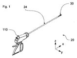
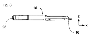
図1は、本発明の筒状軸器具の一実施の形態の概略図である。図は、筒状軸器具の3つの機能的要素であるハンドル110と、やや長い筒状軸24と、筒状軸24の遠位端部(先端側端部)に配置された器具頭部30とを示す。器具頭部30は、筒状軸器具の実際の機能性を与え、組織を切断及び/又は凝固するために用いられる。ハンドル110は、器具頭部30の動きを制御する。特に、組織を固定、凝固及び切断するために、ハンドル110によって口部材10,10’(図2参照)を開閉することができる。
In the following description, the same reference numerals are used for the same members and members having the same functions.
FIG. 1 is a schematic view of an embodiment of the cylindrical shaft device of the present invention. The figure shows a
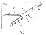
図2は、第1の口部材10と第2の口部材10’とを備えた本発明の器具頭部30の実施の形態を示す。第1の口部材10は、筒状軸24に面する側に、当該筒状軸24にしっかりと連結されるアダプター25を有する縦長体である。第2の口部材10’は、関節40によって第1の口部材10に取り付けられており、組織をつかむ開放位置から組織を固定するための閉止位置に移動させることができる。関節40は、仮想的な支点1又は旋回軸が、第1及び第2の口部材10,10’の外側に位置するように設計される。それゆえに、かかる器具のための従来の関節40とは違って、支点1は、口部材10,10’が係合する領域又は筒状軸24の長手方向軸に近接した当該筒状軸24内に配置されない。図示された関節40の機構は、仮想的な支点1が、第2の口部材10’に面する筒状軸器具の側部の上方に形成されるように作用する。
FIG. 2 shows an embodiment of the
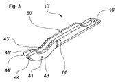
このように移動させられた支点1の特別な利点を、図9の説明図に基づいて示す。支点1が口部材10及び10’の長手方向軸上に実質的に配置される従来の関節を左上隅に示す。前記開放位置では、第2の口部材10’の先端16’は、第1の口部材10の先端16に関して斜め後方にある。しかしながら、図9の他の2つの図に概略的に示される本発明の関節40では、このようなことがない。ここで、支点1は、縦長の両口部材10,10’の長手方向軸の著しく上方に配置されている。第2の口部材10’に対する第1の口部材10により形成された角度について同じ開き状態のときに、第2の口部材10’の先端16’は、第1の口部材10の先端16を通る垂直線上に、又は開いた状態においても実質的に前方に位置づけられる。第2の口部材10’が第1の口部材10に関して開かれる場合、第2の口部材10’の相対的な配置が第1の口部材10に関して変化する回転移動だけではなく、遠位側に方向づけられる、すなわち、第1の口部材10の長手方向軸に平行であり、その先端16の方向への第2の口部材10’の長手方向移動がある。反対に、口部材10,10’の閉じる動作に際して、近位方向への第2の口部材10’の長手方向移動がある。その結果、両口部材10,10’間に位置する組織は、最終的に、器具頭部30に入れられる。さらに、本発明によれば、第2の先端16’の上昇、すなわち、第1及び第2の先端16,16’間の距離は、同じ開き角度では、著しく大きくなる(図9右手側参照)。一実施の形態では、支点への第1の口部材10の長手方向軸の距離に対する口部材10,10’の長さの比は、約10:1である。図9では、明確化のために、口部材10,10’の近接端部(根元側端部)に垂直に取り付けられた延長部によって、支点1の移動が達成されているが、好ましい実施の形態では、支点1の形成は、純粋に仮想的である。この仮想的な設計は、図3−8に基づいて以下に説明するように、溝付ガイドシステムにより達成される。したがって、図3に示されるように、第2の口部材10’は、その先端16’の反対側の近接端部に2つの曲がった関節用ガイドレール41,41’を有する。上方から見ると(図4参照)、これらの関節用ガイドレール41,41’は、第2の口部材10’の長手方向軸に沿って実質的に平行であり、溝を形成するために離間されている。
The special advantage of the
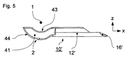
側面から見ると(図5参照)、第2の口部材10’は、スプーン形状の側面を有する。第2の口部材10’の近接端部、特に、関節用ガイドレール41,41’はそれぞれ、上部に、第1の口部材10と係合する凹部43,43’を有する。図6から分かるように、これを達成するために、口部材10は、それぞれ凸状断面を有する2つの関節用ガイドピン42,42’を有する。口部材10,10’の開閉動作に際して、第1の関節用ガイドレール41の凹部43は、隣接する第1の関節用ガイドピン42の凸部を摺動し、第2の関節用ガイドレール41’の凹部43’は、隣接する第2の関節用ガイドピン42’の凸部を摺動する。両関節用ガイドレール41,41’の凹部43,43’及び関節用ガイドピン42,42’の対応する部分の曲率は、仮想的な支点1の位置を決定している。湾曲がより顕著になると、わずかに湾曲しているものと比べて、支点1の位置は、器具頭部30に、より近くなる。図9について説明された効果は、湾曲の程度に応じて生じる。
When viewed from the side (see FIG. 5), the second mouth member 10 'has a spoon-shaped side. Proximal end portions of the
一点だけで連結する関節に比べて、当該ガイド機構又は関節40は、高い安定性という利点をさらに有する。互いに連結した凸部及び凹部により、大面積の接触領域が形成され、関節40は、一点連結の関節よりも、より大きい力を吸収することができる。関節40をさらに安定化させるために、第1の口部材10は、第1の関節用ガイドベアリング46と第2の関節用ガイドベアリング46’とを備える。関節用ガイドピン42,42’と同様に、関節用ベアリング46,46’は、第1の口部材10の側壁の内側に交互に取り付けられる。
Compared to a joint that connects at a single point, the guide mechanism or joint 40 further has the advantage of high stability. The protrusions and recesses connected to each other form a large contact area, and the joint 40 can absorb a larger force than a joint with a single point connection. In order to further stabilize the joint 40, the
第1の関節用ガイドベアリング46及び第1のガイドピン42は、それらの間の空間に第1の関節用ガイドレール41を収容するように間隔があけられる。第1の関節用ガイドベアリング46は、第1の関節用ガイドレール41の凸部44とかみ合う凹部を有する。器具頭部30の開閉では、第1のガイドピン42及び第1の関節用ガイドベアリング46によりガイドされた第1の関節用ガイドレール41は、支点1を中心に回転する。
The first joint guide bearing 46 and the
同様に、第2のガイドピン42’及び関節用ガイドベアリング46’によりガイドされる第2の関節用ガイドレール41’は、支点1を中心に回転する。このために、第2の関節用ガイドレール41’、第2の関節用ガイドピン42’、第2の関節用ガイドレール41’の凸部44’及び第2の関節用ガイドベアリング46’は、第1の関節用ガイドレール41、第1の関節用ガイドピン42、第1の関節用ガイドレール41の凸部44及び第1の関節用ガイドベアリング46に対して対称的に構成され且つ配置される。
Similarly, the second
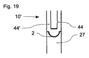
図10に示されるように、引張ストリップ27は、第2の口部材10’の近接端部(根元側ないしは基部側端部)に取り付けられる。より厳密には、関節用ガイドレール41,41’の凸部44,44’のほぼ中央に取り付けられる。これを達成するために、関節用ガイドレール41,41’は、当接縁2を形成するための側面を有する(図5)。好ましくは、この当接縁2は、支点1に平行な直線状ではなく、半円形状で設計される(図19参照)。それに沿って、第2の口部材10’及び引張ストリップ27が溶接される長い当接縁2により、引張ストリップ27への力の伝達は均一化され、溶接部の引張及び曲げ荷重容量は、顕著に増加する。他の実施の形態として、同等の結果を与える鋭角の溶接部又は多数の鋸歯を有する溶接部が考えられる。引張ストリップ27は、支点1に平行な幅方向の寸法が厚さ方向の寸法よりも実質的に大きい。これは、第2の口部材10’の回転時における引張ストリップ27の弾性及び曲げ性を確保する。しかしながら、筒状軸器具の長手方向では、引張ストリップ27は、せん断力が生成され得るように、相対的に硬い。
As shown in FIG. 10, the
また、第2の口部材10’は、図20及び21に示されるように、支点1に対して実質的に放射状である引張バンドピン47を有する。この引張ストリップピン47は、関節用ガイドレール41,41’の凸部44,44’間の中央に配置され、引張ストリップ27の孔内に収容される。こうして、口部材10’と引張ストリップ27とが恒久的に接続される。さらなる溶接は、結合部の安定性を増大させる。
Further, the
引張ストリップ27の第1の端部を、関節用ガイドレール41,41’の凸部44,44’に取り付けることにより、引張ストリップ27により生じる引張応力が、支点1を中心とする曲がった関節用ガイドレール41,41’の円形動作に対して、常に実質的に接線方向に作用することが確保される。したがって、開き角度に関係なく均一な力の伝達が確保される。引張ストリップ27の第2の端部は、操作可能にハンドル110に連結されており、当該ハンドル110に設けられた制御装置により動かすことができる。すでに説明されたように、口部材10,10’の外側上部に位置する仮想的な支点1により、当該支点1と引張ストリップ27の第1の端部との間の距離は、通常の関節により達成される距離よりも顕著に大きい。したがって、前述した筒状軸器具の実施の形態は、非常に高いてこ比を有しており、このてこ比で、第2の口部材10’は、引張ストリップ27の上を移動することができる。
By attaching the first end of the
両口部材10,10’は、それぞれ、組織を固定するための把持面12,12’を有する。したがって、第1の口部材10は、遠位部(先端部)上に、上方に向く第1の把持面12を有する。第1の把持面12は、第1の口部材10の長手方向軸を実質的に横断する凹面が形成される。器具頭部30を閉じた状態で、第2の口部材10’の凸状の第2の把持面12’は、この第1の把持面12に対して、実質的に平行に位置する。
Both
前述した実施の形態では、これらの把持面12,12’は、その後に切断すべき組織をしっかりと固定するのに適しているだけではなく、凝固プロセスのための電極を形成する。これを達成するために、把持面12,12’の一部は導電性であり、印刷導体を介して、ハンドル110による制御も可能な高周波電流源に連結される。したがって、把持された組織は、切断手順に先立って、出血なしでの分離が可能な程度に焼灼することができる。好ましくは、口部材10,10’の少なくとも一部分は、射出成形法によりセラミック材料から製造される。したがって、ガイドエレメント、特に、関節40の関節用ガイドレール41,41’及び関節用ガイドピン42,42’の形成は容易である。セラミック材料の関節40は、口部材10,10’の間、具体的には、凝固のためのそれらの電極間に電気絶縁体を形成する。
In the embodiment described above, these gripping
本実施の形態では、実際の機械的切断プロセスは、凝固の後に行なわれる。これを達成するために、切断具50は、把持面12,12’により画定される固定面x−yに対して平行に移動される(図11参照)。この切断具50は、筒状軸器具の長手方向(x−軸)に刃51の移動が可能であるガイドワイヤ52に加えて、組織を分離するための刃51を備える。
In the present embodiment, the actual mechanical cutting process is performed after solidification. In order to achieve this, the cutting
切断プロセスに先立って、刃51は、組織の早期損傷が起こらないように筒状軸24のほうに引っ込められている。好ましくは、第1の口部材10の刃は、関節用ガイドピン42,42’の位置にある。この開始位置から、刃51を、第2の口部材10’と一体となった斜面55によって、固定面x−y上に移動させる(これについては、図4参照)。この斜面55は、2つの関節用ガイドレール41,41’間に配置される。第2の口部材10’は、刃51又はカッターの移動のための刃ガイド53を提供する。この刃ガイド53は、第2の口部材10’の長手方向軸に沿って伸びる縦長の開口部である。固定面x−yに対して垂直に刃51を保持するために、第2の口部材10’は、その中央領域に、長く延びた溝を形成するように、互いに平行に配置された側部60,60’を有する。刃51又はカッターは、この溝でガイドされる。
Prior to the cutting process, the
口部材10,10’を閉じた後、刃51は、斜面55上方の開始位置から前記溝内に滑るように移動し、組織の上を遠位及び近位に押し引きされ得る。刃51は、その移動が着実に組織を分離することを確保するために、固定面x−yに関して予め荷重をかけられる。予め荷重をかけるための予圧装置は、平面に対して刃51を押圧する、固定面x−yに垂直な力を及ぼす。この力は、ガイドワイヤ52の弾性とその湾曲とによってつくられる。図12から分かるように、ガイドワイヤ52は、刃51により予圧がかけられた面で、固定面x−yに垂直になるように曲げられている。ひだ56は、ガイドワイヤ52の前部に設けられる。切断具50が完全に延ばされた状態で、すなわち、刃51が口部材10,10’の遠位端(先端)に存在する場合に、筒状軸24内のひだが当該軸の遠位端に同様に存在するように、ひだ56は、ガイドワイヤ52と一体にされる。ひだ56は、固定面x−yに垂直なガイドワイヤ52の湾曲により生じる力の少なくとも一部を筒状軸24に移すために用いられ、対応する接触点を有する。ガイドワイヤ52は、ガイドワイヤの近接端部が筒状軸24に平行に動く場合、連結されていないガイドワイヤ52の遠位端部が下方に曲がり、刃51の少なくとも一部が、固定面x−yよりも下に位置するように湾曲される。ガイドワイヤ52は、刃51が、当該ガイドワイヤ52により器具ハンドル30内を前後に移動することができるように、ハンドル110に操作可能に連結される。
After closing the
最も多様な実施の形態が、刃51の設計に関して考えられる。これらを、図13、14及び15に基づいて、以下に述べる。本発明の1つの概念は、刃52が、固定面x−yに実質的に平行に動き、それにより、固定された組織に平行に動く少なくとも1つの部分を有することである。結果的に、切断手順に際して、刃51は、組織が完全に分離されるまで、組織の上を滑るように動く。従来の切断手順と異なり、刃51が切れ味の悪いものである場合でさえも、組織は分離され、機械的圧力により破壊されないことが確保され得る。同様に固定面x−yに平行に形成された切断刃の切断面は、刃51が、1点だけではなく、通常、より長い領域で組織の上に載るという利点を有する。したがって、特定の点での刃51の磨耗が防止される。
The most various embodiments are conceivable for the design of the
図13は、凸状湾曲部を有する半円の刃51を示す。刃51は、ガイドワイヤ52の下面に配置される。この刃は、筒状軸器具の遠位及び近位に湾曲刃54を有する。
FIG. 13 shows a
図14は、一方が他方の後ろにある2つの半円からなる刃51を示す。
FIG. 14 shows a
図15は、遠位に湾曲刃54と、近位にガイドワイヤ52に垂直な部分とを有する刃51を示す。
FIG. 15 shows a
好ましくは、刃51は、全体にわたって微細な歯を有する。
他の実施の形態(例えば、図10を参照)では、ガイドワイヤ52はレールである。当該レールは、ガイドワイヤ52と同じ機能性を有するように設計することができる。固定面x−yに対する予圧は、レール固有の弾性により、あるいは別体の装置(例えば、バネ)により達成することができる。
Preferably, the
In other embodiments (see, eg, FIG. 10), the
本発明の有利な切断具50は、有利な関節形状と併せてこれまで述べられている。しかしながら、両発明は、互いに独立して実施され得る。
したがって、図17及び18は、例えば、第2の口部材10’が溝付ガイドシステムによって第1の口部材と有効に連結されていない器具頭部30における切断具50を示す。ここで、支点1は、口部材10,10’の長手方向軸上に実質的に位置する。
An
Thus, FIGS. 17 and 18 illustrate a
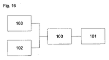
本発明の一実施の形態では、筒状軸器具は、切開監視装置をさらに含む。これは、2つの把持面12,12’間の組織が完全に分離されたことを測定する。本実施の形態では、刃51は、組織が完全に分離した場合、第1の把持面12上に位置する。把持面12は凝固用の電極を含んでいるので、少なくとも部分的に導電性である。本発明によれば、組織が分離した場合に分離面12に機械的に接触する刃51の少なくとも一部分が、同様に、導電性材料から作製される。刃51と把持面12との間の電気的接触は、切開監視装置により測定される。把持された組織は、第2の口部材10’の先端16’から斜面55までの完全な切断移動に際して、刃51と把持面12との間に連続的な電気的接触が存在した場合、完全に切断されていると考えられる。図16から分かるように、前記切開監視装置は、切断手順の進行を測定し、表示するために、処理装置100と、表示装置101と、スイッチ103と道程センサ102とを備える。道程センサ102は、刃51の位置及び移動を測定し、その結果として、全部の刃移動をカバーするのが好ましい観察期間を決めるのを助ける。スイッチ103は、最も単純な場合、導電性の刃1と第1の把持面12とにより形成される。切断対象の組織は一定の導電率を有するので、電気スイッチ103は、低オーム接続が把持面12と刃51との間に存在する場合、閉じられたと考えられるだけである。対応する装置は、処理装置100の上流側に接続される。処理装置100は、全部の観察期間で、刃51と把持面12との間の連続的な低オーム接触があることを確認すると、表示装置101により、把持された組織が完全に分離されたことをユーザーに知らせる。したがって、切断具50は、間に組織を把持することなく把持面12上を刃51が移動すると、装置に損傷を与えるので、注意深く取り扱われる。
In one embodiment of the present invention, the tubular shaft instrument further includes an incision monitoring device. This measures that the tissue between the two
一方、刃51と把持面12との間に直接的な機械的接触があるかどうかを常にユーザーに知らせることもできる。ユーザーが刃51の移動を手動で行なうときには、ユーザーは、組織が適切に分離されたかどうかについて、独立して結論を導き出すことができる。
On the other hand, it is possible to always inform the user whether there is direct mechanical contact between the
さらなる実施の形態では、道程センサ102は、刃ガイド53の遠位端部及び近接端部における2つの電気接触領域を備えており、これら電気接触領域は、刃51と遠位接触領域との間の接触及び刃51と近位接触領域との間の接触を測定することができるように設計される。したがって、処理装置100は、観察期間の開始及び終了を決定することができる。
In a further embodiment, the
図22は、図1のハンドル110の概略図を示す。ハンドル110は、ハンドル本体117を備えており、このハンドル本体117の下方には、第1のハンドルレバー122が一体的に形成されている。このハンドルレバー122は、複数個の指、好ましくは、中指、薬指及び小指を入れるための開口部を有する。第2のハンドルレバー122’は、第1のハンドルレバー122に近接してハンドル本体117に回転可能に連結される。器具頭部30の口部材10,10’は、第1のハンドルレバー122に対して近位及び遠位に第2のハンドルレバー122’が移動することにより開閉され得る。ハンドルレバー122,122’は、ハンドトリガー120を形成し、それにより、筒状軸器具全体が一方の手でガイドされ得るようにユーザーの手に握られ得る。これを達成するために、手は、ハンドルレバー122,122’の部分を包みこむ。ラック124とかみ合う延長部は、ハンドル本体117から離れた方の第2のハンドルレバー122’の端部に配置される。このラック124は、第1のハンドルレバー122におけるハンドル本体117から離れた方の端部において、当該第1のハンドルレバー122の長手方向軸に対して直角に取り付けられる。ラック124の幅は、第2のハンドルレバー122’が少しずつハンドルレバー122に向かって移動することができ、連続した力を加えなくてもその位置に保たれるように設計される。ハンドルレバー122,122’の互いの締め付けを開放するために、それらがもはや係合しないようにラック124は、延長部125から離れるように押圧される。
FIG. 22 shows a schematic view of the
さらに、ハンドル110は、同様にハンドル本体117に回転可能に取り付けられた指トリガー130を有する。切断具50、特に、刃51は、指トリガー130を操作することにより遠位に移動させることができる。ハンドル本体117の内部のバネ要素(図示せず)は、操作後、指トリガー130を開始位置に戻し、その結果、切断具50は近位に移動される。指トリガー130は、ハンドルレバー122,122’をつかむ際に、指トリガー130が、親指により操作され得るように第1のハンドルレバー122の前方において遠位に配置される。
In addition, the
ハンドル110は、ハンドル本体ll7の近位側に、凝固用電流を制御する瞬間的接触スイッチ116を有する。他の実施の形態では、瞬間的接触スイッチ116の代わりに、複数の凝固モードを選択して実行することができる複数個の動作エレメントを有する制御装置を設けることができる。同様に、ハンドル本体117上に表示装置101を設けることが考えられる。
The
本発明の一実施の形態では、筒状軸24及びハンドル110は、筒状軸24が分離可能にハンドル110内に挿入され得るように設計される。これを達成するために、カバーにより閉じられ得る支持開口部112が、ハンドル110の側部に設けられる。
In one embodiment of the present invention, the
したがって、手術に先立って、適切な器具頭部30と切断具50とを有する滅菌された使い捨ての筒状軸24が、再利用可能なハンドル110内に挿入され、その中に固定される。筒状軸24及び関連する装置の再利用は、想定されない。ハンドル本体117は、器具頭部30、切断具51及び筒状軸24の機械的連結のための第1の結合エレメント114、すなわち結合エレメントと、第2の結合エレメント114’、すなわち結合エレメントと、第3の結合エレメント114’’、すなわち結合エレメントとを有する。筒状軸24の近接端部に設けられたリングは、当該筒状軸がハンドル本体117に強固に連結されるように、第3の結合エレメント114’’と係合する。第1の内側チューブアダプター22は、同様に近接端部に配置されたリングにより、第2のハンドルレバー122’と操作可能に連結する第1の結合エレメント114と係合する。第2のハンドルレバー122’の移動は、ハンドル本体117の内部に配置された機構により第1の結合エレメント114に伝達され、この移動を第1の内側チューブアダプター22に伝達する。これは、引張ストリップ27により第2の口部材10’に対して、直接的又は間接的に、機械的に連結される。したがって、筒状軸24に対して第1の内側チューブアダプター22が長手方向に移動することは、口部材10,10’の開閉をもたらす。
Thus, prior to surgery, a sterilized disposable
第2の内側チューブアダプター22’は、第1の内側チューブの内部の第1の内側チューブアダプター22に対して移動可能に配置される。この内側チューブアダプター22’は、ガイドワイヤ52に操作可能に連結され、刃51を移動させる。ハンドル本体ll7に筒状軸24を挿入すると、第2の内側チューブアダプター22’の端部の近位リングと第2の結合エレメント114’とが係合し、指トリガー130によりもたらされる力又は動きを伝達する。
The second inner tube adapter 22 'is movably disposed with respect to the first
使い捨ての筒状軸24をより挿入させやすくするために、当該筒状軸24に取り外し可能な締め具が設けられ、この締め具は、リングが結合エレメント114,114’,114’’に簡単に挿入できるように、内側チューブアダプター22,22’を筒状軸24に対して所定の位置に保持する。
In order to make it easier to insert the disposable
結合エレメント114,114’,114’’は、ハンドル110に対して筒状軸24が回転され得るように設計される。したがって、器具頭部30の配置は、ハンドル110に対して自由に調整され得る。回転に際して、内側チューブアダプター22,22’及び筒状軸24のリングは、結合エレメント114,114’,114’’内で回転し、その結果として、関節を形成する。
The
1 支点
2 当接縁
10,10’ 口部材
12,12’ 把持面
16,16’ 先端
22,22’ 内側チューブアダプター
24 筒状軸
25 アダプター
27 引張ストリップ
30 器具頭部
40 関節
41,41’ 関節用ガイドレール
42,42’ 関節用ガイドピン
43,43’ 関節用ガイドレールの凹部
44,44’ 関節用ガイドレールの凸部
46,46’ 関節用ガイドベアリング
50 切断具
51 刃
52 ガイドワイヤ
53 刃ガイド
54 湾曲刃
55 斜面
56 ひだ
60,60’ 側部
100 処理装置
101 表示装置
102 道程センサ
103 スイッチ
110 ハンドル
112 受け部開口
114,
114’,
114’’ 結合エレメント
116 瞬間的接触スイッチ
117 ハンドル本体
120 ハンドトリガー
122,
122’ ハンドルレバー
124 ラック
125 延長部
130 指トリガー
x x軸
y y軸
z z軸
1
114 ',
114 ''
122 '
Claims (9)
筒状軸(24)と、
この筒状軸の先端に設けられており、それぞれが少なくとも1つの把持面(12,12’)を有する第1及び第2の口部材(10,10’)と、
前記把持面(12,12’)を用いて組織を固定するために口部材(10,10’)が開放位置から閉止位置に移動できるように、当該口部材(10,10’)を回転自在に支持する少なくとも1つの関節(40)と
を備えており、
前記関節(40)は、口部材(10’)が回転移動だけでなく平行移動を行うように、当該口部材(10’)の回転中心である仮想的な支点(1)が口部材(10,10’)の外側に位置するようにされており、且つ、口部材(10,10’)のうち少なくとも一方の先端が、開放時に筒状軸(24)の先端から離反可能であり、更に、関節(40)は、2つの口部材(10,10’)の一方に設けられた関節ガイド(42,42’,46,46’)と、2つの口部材(10,10’)の他方に設けられた少なくとも1つのレール(41,41’)又は溝とを備えていることを特徴とする筒状の軸機器。 A cylindrical shaft device for grasping and / or coagulating and / or separating tissue, in particular a tubular shaft device for electrosurgery,
A cylindrical shaft (24);
First and second mouth members (10, 10 ') each provided at the tip of the cylindrical shaft, each having at least one gripping surface (12, 12');
The mouth member (10, 10 ') is rotatable so that the mouth member (10, 10') can be moved from the open position to the closed position in order to fix the tissue using the gripping surface (12, 12 '). And at least one joint (40) supporting the
The joint (40) has a virtual fulcrum (1) , which is the center of rotation of the mouth member (10 '), so that the mouth member (10') performs not only rotational movement but also parallel movement. , 10 ') are to be positioned on the outside of, and, the mouth member (10, 10' at least one of the distal end of) is Ri away available der from the front end of the tubular shaft (24) upon opening, Further, the joint (40) includes a joint guide (42, 42 ', 46, 46') provided on one of the two mouth members (10, 10 ') and two mouth members (10, 10'). A cylindrical shaft device comprising at least one rail (41, 41 ') or groove provided on the other side .
刃(51)を有しており、固定された組織を切断するための切断具(50)が、駆動手段によって切断方向(x)に移動自在であり、
前記刃(51)は、前記固定面(x−y)にほぼ平行に移動自在にガイドされ、且つ、予め荷重を付与する手段(56)によって、切断している間前記固定面(x−y)に押圧されている請求項1〜7のいずれかに記載の筒状の軸機器。 The mouth member (10, 10 ′) is configured to fix tissue to a fixing surface (xy),
A cutting tool (50) having a blade (51) and capable of cutting a fixed tissue is movable in the cutting direction (x) by a driving means,
The blade (51) is guided so as to be movable substantially parallel to the fixed surface (xy), and is fixed to the fixed surface (xy) while being cut by means (56) for applying a load in advance. The cylindrical shaft device according to any one of claims 1 to 7 , wherein the cylindrical shaft device is pressed.
The cutting guide (53) is a cylindrical shaft apparatus according to the opening member (10, 10 ') 請 Motomeko 3 the blade with the starting position close to the fulcrum (51) that is coming so the.
Applications Claiming Priority (13)
| Application Number | Priority Date | Filing Date | Title |
|---|---|---|---|
| DE102006046920 | 2006-10-05 | ||
| DE200610047204 DE102006047204B4 (en) | 2006-10-05 | 2006-10-05 | Tubular shaft instrument |
| DE102006046919 | 2006-10-05 | ||
| DE102006047204.7 | 2006-10-05 | ||
| DE102006046919.4 | 2006-10-05 | ||
| DE102006047215 | 2006-10-05 | ||
| DE102006047215.2 | 2006-10-05 | ||
| DE102006046920.8 | 2006-10-05 | ||
| DE102006056405A DE102006056405A1 (en) | 2006-11-29 | 2006-11-29 | Tubular shaft device e.g. electrosurgical tubular shaft device, for e.g. coagulating tissue of patient, has pivot for rotatably supporting jaw parts and formed in such manner that rotational axis of pivot lies outside jaw parts |
| DE102006056405.7 | 2006-11-29 | ||
| DE200610059175 DE102006059175A1 (en) | 2006-12-14 | 2006-12-14 | Tubular shaft device e.g. electrosurgical tubular shaft device, for e.g. coagulating tissue of patient, has pivot for rotatably supporting jaw parts and formed in such manner that rotational axis of pivot lies outside jaw parts |
| DE102006059175.5 | 2006-12-14 | ||
| PCT/EP2007/008386 WO2008040483A1 (en) | 2006-10-05 | 2007-09-26 | Tubular shaft instrument |
Publications (2)
| Publication Number | Publication Date |
|---|---|
| JP2010505476A JP2010505476A (en) | 2010-02-25 |
| JP5244804B2 true JP5244804B2 (en) | 2013-07-24 |
Family
ID=38828437
Family Applications (3)
| Application Number | Title | Priority Date | Filing Date |
|---|---|---|---|
| JP2009530779A Active JP5244804B2 (en) | 2006-10-05 | 2007-09-26 | Cylindrical shaft equipment |
| JP2009530780A Expired - Fee Related JP5149903B2 (en) | 2006-10-05 | 2007-09-26 | Medical equipment |
| JP2009530781A Active JP5149904B2 (en) | 2006-10-05 | 2007-09-26 | Cylindrical shaft equipment |
Family Applications After (2)
| Application Number | Title | Priority Date | Filing Date |
|---|---|---|---|
| JP2009530780A Expired - Fee Related JP5149903B2 (en) | 2006-10-05 | 2007-09-26 | Medical equipment |
| JP2009530781A Active JP5149904B2 (en) | 2006-10-05 | 2007-09-26 | Cylindrical shaft equipment |
Country Status (6)
| Country | Link |
|---|---|
| US (3) | US8795275B2 (en) |
| EP (3) | EP2077774B1 (en) |
| JP (3) | JP5244804B2 (en) |
| AT (2) | ATE544412T1 (en) |
| PL (3) | PL2077785T3 (en) |
| WO (4) | WO2008040486A2 (en) |
Families Citing this family (242)
| Publication number | Priority date | Publication date | Assignee | Title |
|---|---|---|---|---|
| US7364577B2 (en) | 2002-02-11 | 2008-04-29 | Sherwood Services Ag | Vessel sealing system |
| ES2364666T3 (en) | 2001-04-06 | 2011-09-12 | Covidien Ag | SHUTTER AND DIVIDER OF GLASSES WITH NON-CONDUCTIVE BUMPER MEMBERS. |
| US11229472B2 (en) | 2001-06-12 | 2022-01-25 | Cilag Gmbh International | Modular battery powered handheld surgical instrument with multiple magnetic position sensors |
| US7799026B2 (en) | 2002-11-14 | 2010-09-21 | Covidien Ag | Compressible jaw configuration with bipolar RF output electrodes for soft tissue fusion |
| US9848938B2 (en) | 2003-11-13 | 2017-12-26 | Covidien Ag | Compressible jaw configuration with bipolar RF output electrodes for soft tissue fusion |
| US7367976B2 (en) | 2003-11-17 | 2008-05-06 | Sherwood Services Ag | Bipolar forceps having monopolar extension |
| CA2561034C (en) | 2005-09-30 | 2014-12-09 | Sherwood Services Ag | Flexible endoscopic catheter with an end effector for coagulating and transfecting tissue |
| US8298232B2 (en) | 2006-01-24 | 2012-10-30 | Tyco Healthcare Group Lp | Endoscopic vessel sealer and divider for large tissue structures |
| PL2077785T3 (en) * | 2006-10-05 | 2012-07-31 | Erbe Elektromedizin | Tubular shaft instrument |
| US8475453B2 (en) | 2006-10-06 | 2013-07-02 | Covidien Lp | Endoscopic vessel sealer and divider having a flexible articulating shaft |
| AU2008221509B2 (en) | 2007-09-28 | 2013-10-10 | Covidien Lp | Dual durometer insulating boot for electrosurgical forceps |
| US8623276B2 (en) | 2008-02-15 | 2014-01-07 | Covidien Lp | Method and system for sterilizing an electrosurgical instrument |
| US8357158B2 (en) | 2008-04-22 | 2013-01-22 | Covidien Lp | Jaw closure detection system |
| US8469956B2 (en) | 2008-07-21 | 2013-06-25 | Covidien Lp | Variable resistor jaw |
| US9089360B2 (en) | 2008-08-06 | 2015-07-28 | Ethicon Endo-Surgery, Inc. | Devices and techniques for cutting and coagulating tissue |
| US8142473B2 (en) | 2008-10-03 | 2012-03-27 | Tyco Healthcare Group Lp | Method of transferring rotational motion in an articulating surgical instrument |
| US8016827B2 (en) | 2008-10-09 | 2011-09-13 | Tyco Healthcare Group Lp | Apparatus, system, and method for performing an electrosurgical procedure |
| US8114122B2 (en) | 2009-01-13 | 2012-02-14 | Tyco Healthcare Group Lp | Apparatus, system, and method for performing an electrosurgical procedure |
| AU2014202850B2 (en) * | 2009-04-07 | 2015-05-28 | Covidien Lp | Vessel sealer and divider with blade deployment alarm |
| US8251994B2 (en) * | 2009-04-07 | 2012-08-28 | Tyco Healthcare Group Lp | Vessel sealer and divider with blade deployment alarm |
| US8187273B2 (en) | 2009-05-07 | 2012-05-29 | Tyco Healthcare Group Lp | Apparatus, system, and method for performing an electrosurgical procedure |
| US8246618B2 (en) | 2009-07-08 | 2012-08-21 | Tyco Healthcare Group Lp | Electrosurgical jaws with offset knife |
| US8663220B2 (en) | 2009-07-15 | 2014-03-04 | Ethicon Endo-Surgery, Inc. | Ultrasonic surgical instruments |
| US8430876B2 (en) | 2009-08-27 | 2013-04-30 | Tyco Healthcare Group Lp | Vessel sealer and divider with knife lockout |
| US8357159B2 (en) | 2009-09-03 | 2013-01-22 | Covidien Lp | Open vessel sealing instrument with pivot assembly |
| US8133254B2 (en) | 2009-09-18 | 2012-03-13 | Tyco Healthcare Group Lp | In vivo attachable and detachable end effector assembly and laparoscopic surgical instrument and methods therefor |
| US8112871B2 (en) | 2009-09-28 | 2012-02-14 | Tyco Healthcare Group Lp | Method for manufacturing electrosurgical seal plates |
| US9024237B2 (en) | 2009-09-29 | 2015-05-05 | Covidien Lp | Material fusing apparatus, system and method of use |
| US8512371B2 (en) | 2009-10-06 | 2013-08-20 | Covidien Lp | Jaw, blade and gap manufacturing for surgical instruments with small jaws |
| US11090104B2 (en) | 2009-10-09 | 2021-08-17 | Cilag Gmbh International | Surgical generator for ultrasonic and electrosurgical devices |
| US8480671B2 (en) | 2010-01-22 | 2013-07-09 | Covidien Lp | Compact jaw including split pivot pin |
| US8556929B2 (en) | 2010-01-29 | 2013-10-15 | Covidien Lp | Surgical forceps capable of adjusting seal plate width based on vessel size |
| EP2459093B1 (en) * | 2010-02-04 | 2013-09-11 | Aesculap AG | Laparoscopic radiofrequency surgical device |
| US8469981B2 (en) | 2010-02-11 | 2013-06-25 | Ethicon Endo-Surgery, Inc. | Rotatable cutting implement arrangements for ultrasonic surgical instruments |
| US8597295B2 (en) | 2010-04-12 | 2013-12-03 | Covidien Lp | Surgical instrument with non-contact electrical coupling |
| US8439913B2 (en) | 2010-04-29 | 2013-05-14 | Covidien Lp | Pressure sensing sealing plate |
| US8968359B2 (en) * | 2010-05-04 | 2015-03-03 | Covidien Lp | Surgical forceps |
| US8409246B2 (en) | 2010-06-02 | 2013-04-02 | Covidien Lp | Apparatus for performing an electrosurgical procedure |
| US8469991B2 (en) | 2010-06-02 | 2013-06-25 | Covidien Lp | Apparatus for performing an electrosurgical procedure |
| US8430877B2 (en) | 2010-06-02 | 2013-04-30 | Covidien Lp | Apparatus for performing an electrosurgical procedure |
| US8409247B2 (en) | 2010-06-02 | 2013-04-02 | Covidien Lp | Apparatus for performing an electrosurgical procedure |
| US8491624B2 (en) | 2010-06-02 | 2013-07-23 | Covidien Lp | Apparatus for performing an electrosurgical procedure |
| US8814864B2 (en) | 2010-08-23 | 2014-08-26 | Covidien Lp | Method of manufacturing tissue sealing electrodes |
| US9113940B2 (en) | 2011-01-14 | 2015-08-25 | Covidien Lp | Trigger lockout and kickback mechanism for surgical instruments |
| EP4364674A1 (en) * | 2011-02-15 | 2024-05-08 | Intuitive Surgical Operations, Inc. | Indicator for knife location in a stapling or vessel sealing instrument |
| US8939972B2 (en) | 2011-05-06 | 2015-01-27 | Covidien Lp | Surgical forceps |
| US8900232B2 (en) | 2011-05-06 | 2014-12-02 | Covidien Lp | Bifurcated shaft for surgical instrument |
| US8685009B2 (en) | 2011-05-16 | 2014-04-01 | Covidien Lp | Thread-like knife for tissue cutting |
| US9844384B2 (en) | 2011-07-11 | 2017-12-19 | Covidien Lp | Stand alone energy-based tissue clips |
| EP2554133B1 (en) * | 2011-08-02 | 2014-01-22 | Erbe Elektromedizin GmbH | Instrument for vessel fusion and separation with two arms and with a curved electrode |
| US8968306B2 (en) | 2011-08-09 | 2015-03-03 | Covidien Lp | Surgical forceps |
| US9060780B2 (en) | 2011-09-29 | 2015-06-23 | Covidien Lp | Methods of manufacturing shafts for surgical instruments |
| US8968309B2 (en) | 2011-11-10 | 2015-03-03 | Covidien Lp | Surgical forceps |
| US8864753B2 (en) | 2011-12-13 | 2014-10-21 | Covidien Lp | Surgical Forceps Connected to Treatment Light Source |
| USD680220S1 (en) | 2012-01-12 | 2013-04-16 | Coviden IP | Slider handle for laparoscopic device |
| US9113897B2 (en) | 2012-01-23 | 2015-08-25 | Covidien Lp | Partitioned surgical instrument |
| US8747434B2 (en) | 2012-02-20 | 2014-06-10 | Covidien Lp | Knife deployment mechanisms for surgical forceps |
| US9011435B2 (en) | 2012-02-24 | 2015-04-21 | Covidien Lp | Method for manufacturing vessel sealing instrument with reduced thermal spread |
| US8887373B2 (en) | 2012-02-24 | 2014-11-18 | Covidien Lp | Vessel sealing instrument with reduced thermal spread and method of manufacture therefor |
| US9439668B2 (en) | 2012-04-09 | 2016-09-13 | Ethicon Endo-Surgery, Llc | Switch arrangements for ultrasonic surgical instruments |
| DE102012007652A1 (en) | 2012-04-18 | 2013-10-24 | Karl Storz Gmbh & Co. Kg | Tool for a medical instrument |
| DE102012007647A1 (en) * | 2012-04-18 | 2013-10-24 | Karl Storz Gmbh & Co. Kg | Tool for a medical instrument |
| US9668807B2 (en) | 2012-05-01 | 2017-06-06 | Covidien Lp | Simplified spring load mechanism for delivering shaft force of a surgical instrument |
| US9034009B2 (en) | 2012-05-01 | 2015-05-19 | Covidien Lp | Surgical forceps |
| US9375258B2 (en) | 2012-05-08 | 2016-06-28 | Covidien Lp | Surgical forceps |
| US9232958B2 (en) | 2012-05-16 | 2016-01-12 | Smith & Nephew, Inc. | Reusable blade hub assembly |
| US8968313B2 (en) | 2012-06-12 | 2015-03-03 | Covidien Lp | Electrosurgical instrument with a knife blade stop |
| PL2679186T3 (en) * | 2012-06-25 | 2015-12-31 | Erbe Elektromedizin | Instrument for vessel fusion and separation |
| US9011436B2 (en) | 2012-06-26 | 2015-04-21 | Covidien Lp | Double-length jaw system for electrosurgical instrument |
| US9192426B2 (en) * | 2012-06-26 | 2015-11-24 | Covidien Lp | Ablation device having an expandable chamber for anchoring the ablation device to tissue |
| US9770255B2 (en) | 2012-06-26 | 2017-09-26 | Covidien Lp | One-piece handle assembly |
| US9510891B2 (en) | 2012-06-26 | 2016-12-06 | Covidien Lp | Surgical instruments with structures to provide access for cleaning |
| US20140005705A1 (en) | 2012-06-29 | 2014-01-02 | Ethicon Endo-Surgery, Inc. | Surgical instruments with articulating shafts |
| US9408622B2 (en) | 2012-06-29 | 2016-08-09 | Ethicon Endo-Surgery, Llc | Surgical instruments with articulating shafts |
| US9351754B2 (en) | 2012-06-29 | 2016-05-31 | Ethicon Endo-Surgery, Llc | Ultrasonic surgical instruments with distally positioned jaw assemblies |
| US9393037B2 (en) | 2012-06-29 | 2016-07-19 | Ethicon Endo-Surgery, Llc | Surgical instruments with articulating shafts |
| US9833285B2 (en) | 2012-07-17 | 2017-12-05 | Covidien Lp | Optical sealing device with cutting ability |
| US10368945B2 (en) | 2012-07-17 | 2019-08-06 | Covidien Lp | Surgical instrument for energy-based tissue treatment |
| US8939975B2 (en) | 2012-07-17 | 2015-01-27 | Covidien Lp | Gap control via overmold teeth and hard stops |
| US9301798B2 (en) | 2012-07-19 | 2016-04-05 | Covidien Lp | Surgical forceps including reposable end effector assemblies |
| US9192421B2 (en) | 2012-07-24 | 2015-11-24 | Covidien Lp | Blade lockout mechanism for surgical forceps |
| EP2879609B2 (en) * | 2012-08-02 | 2022-12-21 | Koninklijke Philips N.V. | Controller definition of a robotic remote center of motion |
| US9636168B2 (en) | 2012-08-09 | 2017-05-02 | Covidien Lp | Electrosurgical instrument including nested knife assembly |
| US9433461B2 (en) | 2012-09-07 | 2016-09-06 | Covidien Lp | Instruments, systems, and methods for sealing tissue structures |
| US9439711B2 (en) | 2012-10-02 | 2016-09-13 | Covidien Lp | Medical devices for thermally treating tissue |
| US9687290B2 (en) | 2012-10-02 | 2017-06-27 | Covidien Lp | Energy-based medical devices |
| US9681908B2 (en) | 2012-10-08 | 2017-06-20 | Covidien Lp | Jaw assemblies for electrosurgical instruments and methods of manufacturing jaw assemblies |
| US9549749B2 (en) | 2012-10-08 | 2017-01-24 | Covidien Lp | Surgical forceps |
| US9526564B2 (en) | 2012-10-08 | 2016-12-27 | Covidien Lp | Electric stapler device |
| US9095367B2 (en) | 2012-10-22 | 2015-08-04 | Ethicon Endo-Surgery, Inc. | Flexible harmonic waveguides/blades for surgical instruments |
| US9375259B2 (en) | 2012-10-24 | 2016-06-28 | Covidien Lp | Electrosurgical instrument including an adhesive applicator assembly |
| US9572529B2 (en) | 2012-10-31 | 2017-02-21 | Covidien Lp | Surgical devices and methods utilizing optical coherence tomography (OCT) to monitor and control tissue sealing |
| US10206583B2 (en) | 2012-10-31 | 2019-02-19 | Covidien Lp | Surgical devices and methods utilizing optical coherence tomography (OCT) to monitor and control tissue sealing |
| US9375205B2 (en) | 2012-11-15 | 2016-06-28 | Covidien Lp | Deployment mechanisms for surgical instruments |
| US20140135804A1 (en) | 2012-11-15 | 2014-05-15 | Ethicon Endo-Surgery, Inc. | Ultrasonic and electrosurgical devices |
| US10772674B2 (en) | 2012-11-15 | 2020-09-15 | Covidien Lp | Deployment mechanisms for surgical instruments |
| US9498281B2 (en) | 2012-11-27 | 2016-11-22 | Covidien Lp | Surgical apparatus |
| US9375256B2 (en) | 2013-02-05 | 2016-06-28 | Covidien Lp | Electrosurgical forceps |
| US10265119B2 (en) | 2013-02-15 | 2019-04-23 | Covidien Lp | Electrosurgical forceps |
| US9713491B2 (en) | 2013-02-19 | 2017-07-25 | Covidien Lp | Method for manufacturing an electrode assembly configured for use with an electrosurigcal instrument |
| US9375262B2 (en) | 2013-02-27 | 2016-06-28 | Covidien Lp | Limited use medical devices |
| US9655673B2 (en) | 2013-03-11 | 2017-05-23 | Covidien Lp | Surgical instrument |
| US10070916B2 (en) | 2013-03-11 | 2018-09-11 | Covidien Lp | Surgical instrument with system and method for springing open jaw members |
| DE102013102418A1 (en) | 2013-03-11 | 2014-09-11 | Ovesco Endoscopy Ag | Surgical DC cutter |
| US9456863B2 (en) | 2013-03-11 | 2016-10-04 | Covidien Lp | Surgical instrument with switch activation control |
| US9877775B2 (en) | 2013-03-12 | 2018-01-30 | Covidien Lp | Electrosurgical instrument with a knife blade stop |
| US9468453B2 (en) | 2013-05-03 | 2016-10-18 | Covidien Lp | Endoscopic surgical forceps |
| USD728786S1 (en) | 2013-05-03 | 2015-05-05 | Covidien Lp | Vessel sealer with mechanical cutter and pistol-grip-style trigger |
| US9622810B2 (en) | 2013-05-10 | 2017-04-18 | Covidien Lp | Surgical forceps |
| US9649151B2 (en) | 2013-05-31 | 2017-05-16 | Covidien Lp | End effector assemblies and methods of manufacturing end effector assemblies for treating and/or cutting tissue |
| EP3003177B1 (en) | 2013-05-31 | 2021-03-10 | Covidien LP | Surgical device with an end-effector assembly for monitoring of tissue during a surgical procedure |
| US9554845B2 (en) | 2013-07-18 | 2017-01-31 | Covidien Lp | Surgical forceps for treating and cutting tissue |
| USD726910S1 (en) | 2013-08-07 | 2015-04-14 | Covidien Lp | Reusable forceps for open vessel sealer with mechanical cutter |
| USD737439S1 (en) | 2013-08-07 | 2015-08-25 | Covidien Lp | Open vessel sealer with mechanical cutter |
| WO2015017994A1 (en) | 2013-08-07 | 2015-02-12 | Covidien Lp | Bipolar surgical instrument |
| USD744644S1 (en) | 2013-08-07 | 2015-12-01 | Covidien Lp | Disposable housing for open vessel sealer with mechanical cutter |
| US9439717B2 (en) | 2013-08-13 | 2016-09-13 | Covidien Lp | Surgical forceps including thermal spread control |
| US10405874B2 (en) | 2013-08-13 | 2019-09-10 | Covidien Lp | Surgical instrument |
| PL2845548T3 (en) | 2013-09-10 | 2017-04-28 | Erbe Elektromedizin Gmbh | Surgical instrument with pivotable jaws |
| US9943357B2 (en) | 2013-09-16 | 2018-04-17 | Covidien Lp | Split electrode for use in a bipolar electrosurgical instrument |
| US9445865B2 (en) | 2013-09-16 | 2016-09-20 | Covidien Lp | Electrosurgical instrument with end-effector assembly including electrically-conductive, tissue-engaging surfaces and switchable bipolar electrodes |
| US9717548B2 (en) | 2013-09-24 | 2017-08-01 | Covidien Lp | Electrode for use in a bipolar electrosurgical instrument |
| US10610289B2 (en) | 2013-09-25 | 2020-04-07 | Covidien Lp | Devices, systems, and methods for grasping, treating, and dividing tissue |
| US10231772B2 (en) | 2013-09-25 | 2019-03-19 | Covidien Lp | Wire retention unit for a surgical instrument |
| US9642671B2 (en) | 2013-09-30 | 2017-05-09 | Covidien Lp | Limited-use medical device |
| US9974601B2 (en) | 2013-11-19 | 2018-05-22 | Covidien Lp | Vessel sealing instrument with suction system |
| US10231776B2 (en) | 2014-01-29 | 2019-03-19 | Covidien Lp | Tissue sealing instrument with tissue-dissecting electrode |
| US10130413B2 (en) | 2014-02-11 | 2018-11-20 | Covidien Lp | Temperature-sensing electrically-conductive tissue-contacting plate and methods of manufacturing same |
| US11090109B2 (en) | 2014-02-11 | 2021-08-17 | Covidien Lp | Temperature-sensing electrically-conductive tissue-contacting plate configured for use in an electrosurgical jaw member, electrosurgical system including same, and methods of controlling vessel sealing using same |
| US10092310B2 (en) | 2014-03-27 | 2018-10-09 | Ethicon Llc | Electrosurgical devices |
| US9737355B2 (en) | 2014-03-31 | 2017-08-22 | Ethicon Llc | Controlling impedance rise in electrosurgical medical devices |
| US10342601B2 (en) | 2014-04-02 | 2019-07-09 | Covidien Lp | Electrosurgical devices including transverse electrode configurations |
| US10278768B2 (en) | 2014-04-02 | 2019-05-07 | Covidien Lp | Electrosurgical devices including transverse electrode configurations |
| JP5829368B1 (en) * | 2014-04-15 | 2015-12-09 | オリンパス株式会社 | Energy treatment tool |
| US9913680B2 (en) | 2014-04-15 | 2018-03-13 | Ethicon Llc | Software algorithms for electrosurgical instruments |
| US9687295B2 (en) | 2014-04-17 | 2017-06-27 | Covidien Lp | Methods of manufacturing a pair of jaw members of an end-effector assembly for a surgical instrument |
| US20150324317A1 (en) | 2014-05-07 | 2015-11-12 | Covidien Lp | Authentication and information system for reusable surgical instruments |
| US10285724B2 (en) | 2014-07-31 | 2019-05-14 | Ethicon Llc | Actuation mechanisms and load adjustment assemblies for surgical instruments |
| US10660694B2 (en) | 2014-08-27 | 2020-05-26 | Covidien Lp | Vessel sealing instrument and switch assemblies thereof |
| US10820939B2 (en) | 2014-09-15 | 2020-11-03 | Covidien Lp | Vessel-sealing device including force-balance interface and electrosurgical system including same |
| US10039592B2 (en) | 2014-09-17 | 2018-08-07 | Covidien Lp | Deployment mechanisms for surgical instruments |
| US10039593B2 (en) | 2014-09-17 | 2018-08-07 | Covidien Lp | Surgical instrument having a bipolar end effector assembly and a deployable monopolar assembly |
| US10080606B2 (en) | 2014-09-17 | 2018-09-25 | Covidien Lp | Method of forming a member of an end effector |
| US10080605B2 (en) | 2014-09-17 | 2018-09-25 | Covidien Lp | Deployment mechanisms for surgical instruments |
| US9987076B2 (en) | 2014-09-17 | 2018-06-05 | Covidien Lp | Multi-function surgical instruments |
| US9918785B2 (en) | 2014-09-17 | 2018-03-20 | Covidien Lp | Deployment mechanisms for surgical instruments |
| US10258360B2 (en) | 2014-09-25 | 2019-04-16 | Covidien Lp | Surgical instruments |
| US10463422B2 (en) | 2014-12-18 | 2019-11-05 | Covidien Lp | Surgical instrument with stopper assembly |
| US10172612B2 (en) | 2015-01-21 | 2019-01-08 | Covidien Lp | Surgical instruments with force applier and methods of use |
| US10245095B2 (en) | 2015-02-06 | 2019-04-02 | Ethicon Llc | Electrosurgical instrument with rotation and articulation mechanisms |
| US10653476B2 (en) | 2015-03-12 | 2020-05-19 | Covidien Lp | Mapping vessels for resecting body tissue |
| US10206736B2 (en) | 2015-03-13 | 2019-02-19 | Covidien Lp | Surgical forceps with scalpel functionality |
| CN104799909B (en) * | 2015-03-19 | 2016-06-29 | 哈尔滨医科大学 | Digestive endoscopy Minimally Invasive Surgery doublejointed sickle knife |
| WO2016169038A1 (en) | 2015-04-24 | 2016-10-27 | Covidien Lp | Multifunctional vessel sealing and divider device |
| US10758257B2 (en) | 2015-04-24 | 2020-09-01 | Covidien Lp | Vessel sealing device with fine dissection function |
| US10226269B2 (en) | 2015-05-27 | 2019-03-12 | Covidien Lp | Surgical forceps |
| US9848935B2 (en) | 2015-05-27 | 2017-12-26 | Covidien Lp | Surgical instruments including components and features facilitating the assembly and manufacturing thereof |
| US9974602B2 (en) | 2015-05-27 | 2018-05-22 | Covidien Lp | Surgical instruments and devices and methods facilitating the manufacture of the same |
| US9956022B2 (en) | 2015-05-27 | 2018-05-01 | Covidien Lp | Surgical forceps and methods of manufacturing the same |
| US10441340B2 (en) | 2015-05-27 | 2019-10-15 | Covidien Lp | Surgical forceps |
| US10722293B2 (en) | 2015-05-29 | 2020-07-28 | Covidien Lp | Surgical device with an end effector assembly and system for monitoring of tissue before and after a surgical procedure |
| US10898256B2 (en) * | 2015-06-30 | 2021-01-26 | Ethicon Llc | Surgical system with user adaptable techniques based on tissue impedance |
| US10765470B2 (en) | 2015-06-30 | 2020-09-08 | Ethicon Llc | Surgical system with user adaptable techniques employing simultaneous energy modalities based on tissue parameters |
| US11058475B2 (en) | 2015-09-30 | 2021-07-13 | Cilag Gmbh International | Method and apparatus for selecting operations of a surgical instrument based on user intention |
| US10595930B2 (en) | 2015-10-16 | 2020-03-24 | Ethicon Llc | Electrode wiping surgical device |
| US10213221B2 (en) | 2015-10-28 | 2019-02-26 | Covidien Lp | Surgical instruments including cam surfaces |
| US10154877B2 (en) | 2015-11-04 | 2018-12-18 | Covidien Lp | Endoscopic surgical instrument |
| US10213250B2 (en) | 2015-11-05 | 2019-02-26 | Covidien Lp | Deployment and safety mechanisms for surgical instruments |
| US10136910B2 (en) | 2015-11-24 | 2018-11-27 | Ethicon Llc | Surgical device with anti-binding features |
| US10172672B2 (en) | 2016-01-11 | 2019-01-08 | Covidien Lp | Jaw force control for electrosurgical forceps |
| US10709469B2 (en) | 2016-01-15 | 2020-07-14 | Ethicon Llc | Modular battery powered handheld surgical instrument with energy conservation techniques |
| US11229471B2 (en) | 2016-01-15 | 2022-01-25 | Cilag Gmbh International | Modular battery powered handheld surgical instrument with selective application of energy based on tissue characterization |
| US10695123B2 (en) | 2016-01-29 | 2020-06-30 | Covidien Lp | Surgical instrument with sensor |
| US10864003B2 (en) | 2016-02-05 | 2020-12-15 | Covidien Lp | Articulation assemblies for use with endoscopic surgical instruments |
| US10555769B2 (en) | 2016-02-22 | 2020-02-11 | Ethicon Llc | Flexible circuits for electrosurgical instrument |
| US10537381B2 (en) | 2016-02-26 | 2020-01-21 | Covidien Lp | Surgical instrument having a bipolar end effector assembly and a deployable monopolar assembly |
| USD828554S1 (en) | 2016-03-09 | 2018-09-11 | Covidien Lp | Contoured blade trigger for an electrosurgical instrument |
| USD819815S1 (en) | 2016-03-09 | 2018-06-05 | Covidien Lp | L-shaped blade trigger for an electrosurgical instrument |
| US10456193B2 (en) | 2016-05-03 | 2019-10-29 | Ethicon Llc | Medical device with a bilateral jaw configuration for nerve stimulation |
| US10517665B2 (en) | 2016-07-14 | 2019-12-31 | Covidien Lp | Devices and methods for tissue sealing and mechanical clipping |
| US10376305B2 (en) | 2016-08-05 | 2019-08-13 | Ethicon Llc | Methods and systems for advanced harmonic energy |
| US10631887B2 (en) | 2016-08-15 | 2020-04-28 | Covidien Lp | Electrosurgical forceps for video assisted thoracoscopic surgery and other surgical procedures |
| US10772642B2 (en) | 2016-08-18 | 2020-09-15 | Covidien Lp | Surgical forceps |
| US10441305B2 (en) | 2016-08-18 | 2019-10-15 | Covidien Lp | Surgical forceps |
| DE102016220286A1 (en) * | 2016-09-20 | 2018-03-22 | Epflex Feinwerktechnik Gmbh | Tubular shaft instrument with distal, rotatable functional part |
| US10813695B2 (en) | 2017-01-27 | 2020-10-27 | Covidien Lp | Reflectors for optical-based vessel sealing |
| US11229480B2 (en) | 2017-02-02 | 2022-01-25 | Covidien Lp | Latching mechanism for in-line activated electrosurgical device |
| US10881445B2 (en) | 2017-02-09 | 2021-01-05 | Covidien Lp | Adapters, systems incorporating the same, and methods for providing an electrosurgical forceps with clip-applying functionality |
| CN110418618A (en) | 2017-03-13 | 2019-11-05 | 柯惠有限合伙公司 | The electrosurgical unit of cutting function with trigger actuation |
| US11172980B2 (en) | 2017-05-12 | 2021-11-16 | Covidien Lp | Electrosurgical forceps for grasping, treating, and/or dividing tissue |
| US10973567B2 (en) | 2017-05-12 | 2021-04-13 | Covidien Lp | Electrosurgical forceps for grasping, treating, and/or dividing tissue |
| US10653475B2 (en) | 2017-06-08 | 2020-05-19 | Covidien Lp | Knife lockout for electrosurgical forceps |
| USD854149S1 (en) | 2017-06-08 | 2019-07-16 | Covidien Lp | End effector for open vessel sealer |
| USD854684S1 (en) | 2017-06-08 | 2019-07-23 | Covidien Lp | Open vessel sealer with mechanical cutter |
| US10512501B2 (en) | 2017-06-08 | 2019-12-24 | Covidien Lp | Electrosurgical apparatus |
| USD859658S1 (en) | 2017-06-16 | 2019-09-10 | Covidien Lp | Vessel sealer for tonsillectomy |
| US11154348B2 (en) | 2017-08-29 | 2021-10-26 | Covidien Lp | Surgical instruments and methods of assembling surgical instruments |
| US10532187B2 (en) | 2017-10-17 | 2020-01-14 | Biosense Webster (Israel) Ltd. | Reusable catheter handle system |
| US11354301B2 (en) | 2017-11-13 | 2022-06-07 | LendingClub Bank, National Association | Multi-system operation audit log |
| US11556520B2 (en) | 2017-11-13 | 2023-01-17 | Lendingclub Corporation | Techniques for automatically addressing anomalous behavior |
| JP7064868B2 (en) | 2017-12-26 | 2022-05-11 | リンテック株式会社 | Sheet supply device and sheet supply method, and sheet pasting device and sheet pasting method |
| US11123132B2 (en) | 2018-04-09 | 2021-09-21 | Covidien Lp | Multi-function surgical instruments and assemblies therefor |
| US10828756B2 (en) | 2018-04-24 | 2020-11-10 | Covidien Lp | Disassembly methods facilitating reprocessing of multi-function surgical instruments |
| US11033289B2 (en) | 2018-05-02 | 2021-06-15 | Covidien Lp | Jaw guard for surgical forceps |
| US11109930B2 (en) | 2018-06-08 | 2021-09-07 | Covidien Lp | Enhanced haptic feedback system |
| US11612403B2 (en) | 2018-10-03 | 2023-03-28 | Covidien Lp | Multi-function surgical transection instrument |
| PL3632354T3 (en) | 2018-10-05 | 2022-11-07 | Erbe Elektromedizin Gmbh | Tissue forceps |
| USD904611S1 (en) | 2018-10-10 | 2020-12-08 | Bolder Surgical, Llc | Jaw design for a surgical instrument |
| US11471211B2 (en) | 2018-10-12 | 2022-10-18 | Covidien Lp | Electrosurgical forceps |
| US11376062B2 (en) | 2018-10-12 | 2022-07-05 | Covidien Lp | Electrosurgical forceps |
| US10881452B2 (en) | 2018-10-16 | 2021-01-05 | Covidien Lp | Method of assembling an end effector for a surgical instrument |
| US11350982B2 (en) | 2018-12-05 | 2022-06-07 | Covidien Lp | Electrosurgical forceps |
| US11246648B2 (en) | 2018-12-10 | 2022-02-15 | Covidien Lp | Surgical forceps with bilateral and unilateral jaw members |
| US11147613B2 (en) | 2019-03-15 | 2021-10-19 | Covidien Lp | Surgical instrument with increased lever stroke |
| US11523861B2 (en) | 2019-03-22 | 2022-12-13 | Covidien Lp | Methods for manufacturing a jaw assembly for an electrosurgical forceps |
| US11576696B2 (en) | 2019-03-29 | 2023-02-14 | Covidien Lp | Engagement features and methods for attaching a drive rod to a knife blade in an articulating surgical instrument |
| US11490917B2 (en) | 2019-03-29 | 2022-11-08 | Covidien Lp | Drive rod and knife blade for an articulating surgical instrument |
| US11490916B2 (en) | 2019-03-29 | 2022-11-08 | Covidien Lp | Engagement features and methods for attaching a drive rod to a knife blade in an articulating surgical instrument |
| US11170029B2 (en) | 2019-05-31 | 2021-11-09 | Lendingclub Corporation | Multi-user cross-device tracking |
| US11607267B2 (en) | 2019-06-10 | 2023-03-21 | Covidien Lp | Electrosurgical forceps |
| PL239734B1 (en) | 2019-12-27 | 2022-01-03 | Konmex Spolka Z Ograniczona Odpowiedzialnoscia | Laparoscopic instrument |
| US11786291B2 (en) | 2019-12-30 | 2023-10-17 | Cilag Gmbh International | Deflectable support of RF energy electrode with respect to opposing ultrasonic blade |
| US11452525B2 (en) | 2019-12-30 | 2022-09-27 | Cilag Gmbh International | Surgical instrument comprising an adjustment system |
| US11937863B2 (en) | 2019-12-30 | 2024-03-26 | Cilag Gmbh International | Deflectable electrode with variable compression bias along the length of the deflectable electrode |
| US11911063B2 (en) | 2019-12-30 | 2024-02-27 | Cilag Gmbh International | Techniques for detecting ultrasonic blade to electrode contact and reducing power to ultrasonic blade |
| US11759251B2 (en) | 2019-12-30 | 2023-09-19 | Cilag Gmbh International | Control program adaptation based on device status and user input |
| US11986201B2 (en) | 2019-12-30 | 2024-05-21 | Cilag Gmbh International | Method for operating a surgical instrument |
| US11950797B2 (en) | 2019-12-30 | 2024-04-09 | Cilag Gmbh International | Deflectable electrode with higher distal bias relative to proximal bias |
| US11696776B2 (en) | 2019-12-30 | 2023-07-11 | Cilag Gmbh International | Articulatable surgical instrument |
| US11779329B2 (en) | 2019-12-30 | 2023-10-10 | Cilag Gmbh International | Surgical instrument comprising a flex circuit including a sensor system |
| US11812957B2 (en) | 2019-12-30 | 2023-11-14 | Cilag Gmbh International | Surgical instrument comprising a signal interference resolution system |
| US11779387B2 (en) | 2019-12-30 | 2023-10-10 | Cilag Gmbh International | Clamp arm jaw to minimize tissue sticking and improve tissue control |
| US11944366B2 (en) | 2019-12-30 | 2024-04-02 | Cilag Gmbh International | Asymmetric segmented ultrasonic support pad for cooperative engagement with a movable RF electrode |
| US20210196357A1 (en) | 2019-12-30 | 2021-07-01 | Ethicon Llc | Electrosurgical instrument with asynchronous energizing electrodes |
| US11660089B2 (en) | 2019-12-30 | 2023-05-30 | Cilag Gmbh International | Surgical instrument comprising a sensing system |
| US11684412B2 (en) | 2019-12-30 | 2023-06-27 | Cilag Gmbh International | Surgical instrument with rotatable and articulatable surgical end effector |
| US11937866B2 (en) | 2019-12-30 | 2024-03-26 | Cilag Gmbh International | Method for an electrosurgical procedure |
| US20210196359A1 (en) | 2019-12-30 | 2021-07-01 | Ethicon Llc | Electrosurgical instruments with electrodes having energy focusing features |
| US11376030B2 (en) | 2020-02-10 | 2022-07-05 | Covidien Lp | Devices and methods facilitating the manufacture of surgical instruments |
| US11622804B2 (en) | 2020-03-16 | 2023-04-11 | Covidien Lp | Forceps with linear trigger mechanism |
| US11844562B2 (en) | 2020-03-23 | 2023-12-19 | Covidien Lp | Electrosurgical forceps for grasping, treating, and/or dividing tissue |
| CN112472213B (en) * | 2020-11-27 | 2022-03-01 | 中国人民解放军总医院第五医学中心 | Tumor clamping tool for radiotherapy |
Family Cites Families (43)
| Publication number | Priority date | Publication date | Assignee | Title |
|---|---|---|---|---|
| US4162397A (en) * | 1978-06-28 | 1979-07-24 | The United States Of America As Represented By The Secretary Of The Navy | Fiber optic acoustic sensor |
| US4297887A (en) * | 1980-02-19 | 1981-11-03 | The United States Of America As Represented By The Secretary Of The Navy | High-sensitivity, low-noise, remote optical fiber |
| US4363114A (en) * | 1981-01-21 | 1982-12-07 | The United States Of America As Represented By The Secretary Of The Navy | Low noise remote optical fiber sound detector |
| US4854706A (en) * | 1987-07-27 | 1989-08-08 | Virginia Tech Intellectual Properties, Inc. | Modal domain optical fiber sensors |
| US5626609A (en) * | 1990-10-05 | 1997-05-06 | United States Surgical Corporation | Endoscopic surgical instrument |
| US5396900A (en) * | 1991-04-04 | 1995-03-14 | Symbiosis Corporation | Endoscopic end effectors constructed from a combination of conductive and non-conductive materials and useful for selective endoscopic cautery |
| DE4204051C2 (en) * | 1992-02-12 | 1994-12-08 | Karl Von Rauch | Anvil scissors for surgical purposes |
| US5293863A (en) | 1992-05-08 | 1994-03-15 | Loma Linda University Medical Center | Bladed endoscopic retractor |
| US5445638B1 (en) * | 1993-03-08 | 1998-05-05 | Everest Medical Corp | Bipolar coagulation and cutting forceps |
| US5582617A (en) * | 1993-07-21 | 1996-12-10 | Charles H. Klieman | Surgical instrument for endoscopic and general surgery |
| US5709680A (en) | 1993-07-22 | 1998-01-20 | Ethicon Endo-Surgery, Inc. | Electrosurgical hemostatic device |
| US5431674A (en) * | 1993-09-07 | 1995-07-11 | Pa Consulting Group | Compound motion cutting device |
| US5458598A (en) * | 1993-12-02 | 1995-10-17 | Cabot Technology Corporation | Cutting and coagulating forceps |
| DE4421822C1 (en) | 1994-06-22 | 1995-10-26 | Karlsruhe Forschzent | Bipolar high frequency coagulation apparatus |
| US5562694A (en) * | 1994-10-11 | 1996-10-08 | Lasersurge, Inc. | Morcellator |
| DE4444166C2 (en) | 1994-12-12 | 1998-09-24 | Urotech Med Tech Gmbh | Flexible knife device for surgical purposes |
| US5611798A (en) | 1995-03-02 | 1997-03-18 | Eggers; Philip E. | Resistively heated cutting and coagulating surgical instrument |
| US5599350A (en) | 1995-04-03 | 1997-02-04 | Ethicon Endo-Surgery, Inc. | Electrosurgical clamping device with coagulation feedback |
| EP0843537A1 (en) * | 1995-06-27 | 1998-05-27 | Symbiosis Corporation | Bipolar endoscopic surgical scissor blades and instrument incorporating the same |
| AU703455B2 (en) * | 1995-10-20 | 1999-03-25 | Ethicon Endo-Surgery, Inc. | Self protecting knife for curved jaw surgical instruments |
| US6019780A (en) | 1996-12-17 | 2000-02-01 | Tnco, Inc. | Dual pin and groove pivot for micro-instrument |
| US6626901B1 (en) * | 1997-03-05 | 2003-09-30 | The Trustees Of Columbia University In The City Of New York | Electrothermal instrument for sealing and joining or cutting tissue |
| JP3986127B2 (en) * | 1997-08-06 | 2007-10-03 | オリンパス株式会社 | Endoscopic surgical instrument |
| US6679882B1 (en) | 1998-06-22 | 2004-01-20 | Lina Medical Aps | Electrosurgical device for coagulating and for making incisions, a method of severing blood vessels and a method of coagulating and for making incisions in or severing tissue |
| US6483619B1 (en) * | 1998-08-12 | 2002-11-19 | Lucent Technologies Inc. | Optical-interference microphone |
| DE19940689A1 (en) | 1999-08-27 | 2001-04-05 | Storz Karl Gmbh & Co Kg | Bipolar medical instrument |
| DE10031773B4 (en) * | 2000-05-04 | 2007-11-29 | Erbe Elektromedizin Gmbh | Surgical gripping instrument, in particular tweezers or forceps |
| US6500176B1 (en) * | 2000-10-23 | 2002-12-31 | Csaba Truckai | Electrosurgical systems and techniques for sealing tissue |
| US6443970B1 (en) * | 2001-01-24 | 2002-09-03 | Ethicon, Inc. | Surgical instrument with a dissecting tip |
| US6775575B2 (en) * | 2001-02-26 | 2004-08-10 | D. Bommi Bommannan | System and method for reducing post-surgical complications |
| US7083618B2 (en) | 2001-04-06 | 2006-08-01 | Sherwood Services Ag | Vessel sealer and divider |
| US6905497B2 (en) | 2001-10-22 | 2005-06-14 | Surgrx, Inc. | Jaw structure for electrosurgical instrument |
| DE10152551A1 (en) * | 2001-10-24 | 2003-07-24 | Martin Storz | Modular tubular-shafted surgical instrument has handle, carrier part, operating bar, gripper lever and holder |
| US20030114851A1 (en) | 2001-12-13 | 2003-06-19 | Csaba Truckai | Electrosurgical jaws for controlled application of clamping pressure |
| ES2373679T3 (en) | 2003-06-13 | 2012-02-07 | Covidien Ag | SUTURE DEVICE AND GLASS DIVIDER FOR USE WITH TROCARES AND SMALL CANNULES. |
| BRPI0507008A (en) * | 2004-01-23 | 2007-10-30 | Ams Res Corp | surgical instrument, methods of performing a hysterotomy and tissue sectioning, and |
| US7632270B2 (en) | 2004-01-26 | 2009-12-15 | Bovie Medical Corporation | Multi-mode surgical instrument |
| JP2005323723A (en) * | 2004-05-13 | 2005-11-24 | Aisin Kiko Co Ltd | Surgery apparatus |
| DE102004026179B4 (en) | 2004-05-14 | 2009-01-22 | Erbe Elektromedizin Gmbh | Electrosurgical instrument |
| DE102004040959B4 (en) | 2004-08-24 | 2008-12-24 | Erbe Elektromedizin Gmbh | Surgical instrument |
| DE102004049243B4 (en) * | 2004-10-01 | 2008-07-10 | Fabrizio Dr. Caroli | Surgical instrument |
| DE102006047204B4 (en) | 2006-10-05 | 2015-04-23 | Erbe Elektromedizin Gmbh | Tubular shaft instrument |
| PL2077785T3 (en) | 2006-10-05 | 2012-07-31 | Erbe Elektromedizin | Tubular shaft instrument |
-
2007
- 2007-09-26 PL PL07818469T patent/PL2077785T3/en unknown
- 2007-09-26 PL PL07818472T patent/PL2077774T3/en unknown
- 2007-09-26 US US12/444,336 patent/US8795275B2/en active Active
- 2007-09-26 US US12/444,379 patent/US8133224B2/en not_active Expired - Fee Related
- 2007-09-26 WO PCT/EP2007/008389 patent/WO2008040486A2/en active Application Filing
- 2007-09-26 US US12/444,356 patent/US8142474B2/en active Active
- 2007-09-26 AT AT07818469T patent/ATE544412T1/en active
- 2007-09-26 WO PCT/EP2007/008386 patent/WO2008040483A1/en active Application Filing
- 2007-09-26 AT AT07818471T patent/ATE538736T1/en active
- 2007-09-26 JP JP2009530779A patent/JP5244804B2/en active Active
- 2007-09-26 WO PCT/EP2007/008388 patent/WO2008040485A2/en active Application Filing
- 2007-09-26 JP JP2009530780A patent/JP5149903B2/en not_active Expired - Fee Related
- 2007-09-26 WO PCT/EP2007/008387 patent/WO2008040484A2/en active Application Filing
- 2007-09-26 PL PL07818471T patent/PL2077773T3/en unknown
- 2007-09-26 JP JP2009530781A patent/JP5149904B2/en active Active
- 2007-09-26 EP EP07818472.8A patent/EP2077774B1/en active Active
- 2007-09-26 EP EP07818469A patent/EP2077785B1/en active Active
- 2007-09-26 EP EP07818471A patent/EP2077773B1/en not_active Not-in-force
Also Published As
| Publication number | Publication date |
|---|---|
| WO2008040484A2 (en) | 2008-04-10 |
| JP2010505477A (en) | 2010-02-25 |
| WO2008040485A2 (en) | 2008-04-10 |
| EP2077774B1 (en) | 2014-09-10 |
| EP2077785A1 (en) | 2009-07-15 |
| JP5149904B2 (en) | 2013-02-20 |
| EP2077773A2 (en) | 2009-07-15 |
| JP2010505476A (en) | 2010-02-25 |
| PL2077774T3 (en) | 2015-02-27 |
| EP2077773B1 (en) | 2011-12-28 |
| PL2077773T3 (en) | 2012-05-31 |
| US20100030213A1 (en) | 2010-02-04 |
| ATE544412T1 (en) | 2012-02-15 |
| EP2077785B1 (en) | 2012-02-08 |
| PL2077785T3 (en) | 2012-07-31 |
| US20090326531A1 (en) | 2009-12-31 |
| JP5149903B2 (en) | 2013-02-20 |
| WO2008040484A3 (en) | 2008-07-17 |
| JP2010505478A (en) | 2010-02-25 |
| WO2008040483A1 (en) | 2008-04-10 |
| US8142474B2 (en) | 2012-03-27 |
| US8795275B2 (en) | 2014-08-05 |
| EP2077774A2 (en) | 2009-07-15 |
| WO2008040485A3 (en) | 2008-07-17 |
| US8133224B2 (en) | 2012-03-13 |
| US20100016879A1 (en) | 2010-01-21 |
| WO2008040486A2 (en) | 2008-04-10 |
| ATE538736T1 (en) | 2012-01-15 |
| WO2008040486A3 (en) | 2008-07-17 |
Similar Documents
| Publication | Publication Date | Title |
|---|---|---|
| JP5244804B2 (en) | Cylindrical shaft equipment | |
| US11510693B2 (en) | Forceps with tissue stops | |
| CN101522118B (en) | Medical instrument | |
| CN108430350B (en) | Forceps with tissue stop | |
| JP5636449B2 (en) | High frequency treatment tool | |
| EP2040634B1 (en) | Surgical sealing and cutting apparatus | |
| US6110171A (en) | Electrosurgical cutting and coagulating instrument for open surgery | |
| JP2011521723A (en) | Surgical instruments and methods | |
| WO2008070718A1 (en) | Monopolar resection device and method of use | |
| WO2007102586A1 (en) | Treatment instrument for endoscope | |
| JP2004524920A (en) | Electrosurgical instruments to reduce flashover | |
| WO2002058547A2 (en) | Electrosurical instrument with minimally invasive jaws | |
| US11478264B2 (en) | Electrosurgical forceps with resilient jaws | |
| CN108463182B (en) | Clamp jaw mechanism | |
| KR102076622B1 (en) | Detachable current connection device for medical snare and medical snare using it | |
| AU2001247942B2 (en) | Electrosurgical instrument reducing flashover | |
| AU2001247942A1 (en) | Electrosurgical instrument reducing flashover |
Legal Events
| Date | Code | Title | Description |
|---|---|---|---|
| A621 | Written request for application examination |
Free format text: JAPANESE INTERMEDIATE CODE: A621 Effective date: 20100628 |
|
| A977 | Report on retrieval |
Free format text: JAPANESE INTERMEDIATE CODE: A971007 Effective date: 20120425 |
|
| A131 | Notification of reasons for refusal |
Free format text: JAPANESE INTERMEDIATE CODE: A131 Effective date: 20120501 |
|
| A521 | Request for written amendment filed |
Free format text: JAPANESE INTERMEDIATE CODE: A523 Effective date: 20120625 |
|
| A02 | Decision of refusal |
Free format text: JAPANESE INTERMEDIATE CODE: A02 Effective date: 20121009 |
|
| A521 | Request for written amendment filed |
Free format text: JAPANESE INTERMEDIATE CODE: A523 Effective date: 20130206 |
|
| A911 | Transfer to examiner for re-examination before appeal (zenchi) |
Free format text: JAPANESE INTERMEDIATE CODE: A911 Effective date: 20130214 |
|
| TRDD | Decision of grant or rejection written | ||
| A01 | Written decision to grant a patent or to grant a registration (utility model) |
Free format text: JAPANESE INTERMEDIATE CODE: A01 Effective date: 20130326 |
|
| A61 | First payment of annual fees (during grant procedure) |
Free format text: JAPANESE INTERMEDIATE CODE: A61 Effective date: 20130408 |
|
| FPAY | Renewal fee payment (event date is renewal date of database) |
Free format text: PAYMENT UNTIL: 20160412 Year of fee payment: 3 |
|
| R150 | Certificate of patent or registration of utility model |
Free format text: JAPANESE INTERMEDIATE CODE: R150 Ref document number: 5244804 Country of ref document: JP Free format text: JAPANESE INTERMEDIATE CODE: R150 |
|
| R250 | Receipt of annual fees |
Free format text: JAPANESE INTERMEDIATE CODE: R250 |
|
| R250 | Receipt of annual fees |
Free format text: JAPANESE INTERMEDIATE CODE: R250 |
|
| R250 | Receipt of annual fees |
Free format text: JAPANESE INTERMEDIATE CODE: R250 |
|
| R250 | Receipt of annual fees |
Free format text: JAPANESE INTERMEDIATE CODE: R250 |
|
| R250 | Receipt of annual fees |
Free format text: JAPANESE INTERMEDIATE CODE: R250 |
|
| R250 | Receipt of annual fees |
Free format text: JAPANESE INTERMEDIATE CODE: R250 |
|
| R250 | Receipt of annual fees |
Free format text: JAPANESE INTERMEDIATE CODE: R250 |
|
| R250 | Receipt of annual fees |
Free format text: JAPANESE INTERMEDIATE CODE: R250 |
|
| R250 | Receipt of annual fees |
Free format text: JAPANESE INTERMEDIATE CODE: R250 |