JP5243092B2 - Rack type air conditioner - Google Patents
Rack type air conditioner Download PDFInfo
- Publication number
- JP5243092B2 JP5243092B2 JP2008110461A JP2008110461A JP5243092B2 JP 5243092 B2 JP5243092 B2 JP 5243092B2 JP 2008110461 A JP2008110461 A JP 2008110461A JP 2008110461 A JP2008110461 A JP 2008110461A JP 5243092 B2 JP5243092 B2 JP 5243092B2
- Authority
- JP
- Japan
- Prior art keywords
- air conditioner
- rack
- type air
- exhaust
- blower fan
- Prior art date
- Legal status (The legal status is an assumption and is not a legal conclusion. Google has not performed a legal analysis and makes no representation as to the accuracy of the status listed.)
- Active
Links
- 239000003570 air Substances 0.000 claims description 117
- 239000003507 refrigerant Substances 0.000 claims description 29
- 238000004378 air conditioning Methods 0.000 claims description 27
- 239000012080 ambient air Substances 0.000 claims description 9
- 238000001816 cooling Methods 0.000 claims description 8
- 230000005484 gravity Effects 0.000 claims description 2
- 239000000725 suspension Substances 0.000 claims 1
- 238000010586 diagram Methods 0.000 description 12
- 238000004891 communication Methods 0.000 description 9
- 230000002441 reversible effect Effects 0.000 description 5
- 230000007423 decrease Effects 0.000 description 4
- UGFAIRIUMAVXCW-UHFFFAOYSA-N Carbon monoxide Chemical compound [O+]#[C-] UGFAIRIUMAVXCW-UHFFFAOYSA-N 0.000 description 3
- 238000007664 blowing Methods 0.000 description 3
- 238000001514 detection method Methods 0.000 description 3
- 230000000903 blocking effect Effects 0.000 description 2
- 238000001704 evaporation Methods 0.000 description 2
- 239000007788 liquid Substances 0.000 description 2
- 238000000034 method Methods 0.000 description 2
- 238000010276 construction Methods 0.000 description 1
- 238000007796 conventional method Methods 0.000 description 1
- 230000002542 deteriorative effect Effects 0.000 description 1
- 230000008020 evaporation Effects 0.000 description 1
- 230000020169 heat generation Effects 0.000 description 1
- 238000005192 partition Methods 0.000 description 1
- 238000005057 refrigeration Methods 0.000 description 1
- 238000009423 ventilation Methods 0.000 description 1
Images


Landscapes
- Air-Flow Control Members (AREA)
- Air Conditioning Control Device (AREA)
- Central Air Conditioning (AREA)
- Ventilation (AREA)
Description
本発明は、ラック型空調機を含むラック型空調機に係り、特にアンビエント空調と局所空調を併用する情報通信機械室の空調システムに好適なラック型空調機に関する。 The present invention relates to a rack type air conditioner including a rack type air conditioner, and more particularly to a rack type air conditioner suitable for an air conditioning system of an information communication machine room that uses both ambient air conditioning and local air conditioning.
近年、情報通信(ICT)機器の高速化、大容量化、高密度化が急速に進んでいる。これらの機器は、米国IEA規格に準ずる19インチサーバラックに格納され、情報通信機械室(データセンタ)に収容されるのが一般的である。サーバラックは前面から冷気を吸込み、上面又は背面から排気するタイプが多く、各ラックは同方向を向けて横一列に配置される。機械室内には、このようなラック列が複数列、隣接する列の吸気面と吸気面、排気面と排気面とを対向させて配置される。ここに、吸気面に挟まれた通路は、二重床から冷気が供給されることからコールドアイルと呼ばれる。これに対し排気面に挟まれた通路は、ラックからの排気で温度が上がるためホットアイルと呼ばれる。
この場合、二重床からの冷気供給のみで室全体を均一に空調する従来の方式(アンビエント空調方式)では、ラックからの発熱の偏在によりコールドアイルに局所的な高温エリアが生じ、情報通信機器・装置の高温障害発生という問題が生じる。このような問題を解消すべく、局所冷却のためにコールドアイルの上方に空調機を設置する技術が提案されている(例えば、特許文献1)。
In recent years, information communication (ICT) devices are rapidly increasing in speed, capacity, and density. These devices are generally stored in a 19-inch server rack conforming to the US IEA standard and housed in an information communication machine room (data center). Server racks often take in cool air from the front and exhaust from the top or back, and each rack is arranged in a horizontal row in the same direction. A plurality of such rack rows are arranged in the machine room, the intake surfaces and the intake surfaces of adjacent rows, and the exhaust surfaces and the exhaust surfaces are opposed to each other. Here, the passage between the intake surfaces is called cold aisle because cold air is supplied from the double floor. On the other hand, the passage between the exhaust surfaces is called hot aisle because the temperature rises due to exhaust from the rack.
In this case, in the conventional method (ambient air conditioning method) that uniformly air-conditions the entire room only by supplying cold air from the double floor, a local high temperature area is generated in the cold aisle due to uneven distribution of heat from the rack, and information communication equipment・ The problem of high-temperature failure of the equipment occurs. In order to solve such a problem, a technique for installing an air conditioner above a cold aisle for local cooling has been proposed (for example, Patent Document 1).
図12は、この方式によるラック空調システム100を示すものであり、機械室101内のサーバラック列104a、104b間に形成されるコールドアイル105の上方に局所空調機102を設置する。これにより各サーバラックは、アンビエント空調機107により二重床空間106を介して供給される冷気、及び、局所空調機102により上方から供給される冷気により冷却されることになる。
一方、局所空調機をラック列内に配置する方式もあり、特に、スペース効率向上等を図るため、サーバラックと同一モジュールとするラック型空調機も実用化されている。ラック型空調機は、吸排気の方向がサーバラック2とは逆向き、すなわちホットアイル空間の高温排気を吸込み、コールドアイル側に冷却空気を吹き出すように配置される。
On the other hand, there is a system in which local air conditioners are arranged in a rack row. In particular, a rack type air conditioner having the same module as a server rack has been put into practical use in order to improve space efficiency. The rack type air conditioner is disposed so that the direction of intake and exhaust is opposite to that of the
しかしながら、情報通信機械室の空調システムでは、コールドアイル空間への供給風量とサーバラックが吸い込む風量の総和とを常にバランスさせておくため、局所空調機がサーモOFFのときに冷媒循環のみ停止し、送風ファンは停止しないのが一般的である。このためサーモOFF中は、局所空調機はホットアイル側の高温排気を吸い込んで直接吹き出すことになるため、コールドアイル側温度が急激に上昇し、情報通信機器・装置の許容上限温度を逸脱する恐れがある。
サーモOFF時に送風ファンを停止する方式のラック型空調機であっても、ICT機器内蔵のファンにより、コールドアイル側からホットアイル側へ常に空気が送られるため、ホットアイル側の気圧がコールドアイル側より高い場合が多い。この場合、圧力差によりラック型空調機のファンを停止させても、空調機の内部を通ってホットアイル側からコールドアイル側に気流が生じ、コールドアイルの環境を悪化させる。特に、アイルキャッピングを行っている場合は、その圧力差が大きくなるため影響が大きい。
本発明は、このような問題を解決するためのものであって、ラック型空調機の能力低下時において、情報通信機器・装置の高温障害発生を回避可能とするラック型空調機を提供するものである。
However, in the air conditioning system of the information communication machine room, in order to always balance the air volume supplied to the cold aisle space and the total air volume sucked by the server rack, only the refrigerant circulation is stopped when the local air conditioner is thermo-OFF, Generally, the blower fan does not stop. For this reason, since the local air conditioner sucks hot exhaust on the hot aisle side and blows it out directly while the thermo is off, the cold aisle side temperature may rise rapidly and deviate from the allowable upper limit temperature of the information communication equipment / device. There is.
Even with rack type air conditioners that shut off the blower fan when the thermo is turned off, air is always sent from the cold aisle side to the hot aisle side by the fan built in the ICT equipment, so the air pressure on the hot aisle side is the cold aisle side. Often higher. In this case, even if the fan of the rack type air conditioner is stopped due to the pressure difference, an air flow is generated from the hot aisle side to the cold aisle side through the inside of the air conditioner, thereby deteriorating the cold aisle environment. In particular, when aisle capping is performed, the pressure difference becomes large, so the influence is great.
The present invention is intended to solve such a problem, and provides a rack-type air conditioner that can avoid the occurrence of a high-temperature failure of information communication equipment and devices when the capacity of the rack-type air conditioner is reduced. It is.
本発明は以下の内容をその要旨とする。すなわち、本発明に係るラック型空調機は、
(1)複数のサーバラック列により、コールドアイルとホットアイルとが形成される室内において、アンビエント空調機による二重床吹き出し空調と、ラック型空調機による局所空調と、を併用する空調システムに用いるラック型空調機であって、ホットアイル側の高温排気を吸い込み、冷却空気をコールドアイル側に吹き出す送風ファンと、所定の運転条件に連動して、高温排気の流入又は遮断を制御する排気流入制御手段と、を備えて成ることを特徴とする。
本発明において、コールドアイルとホットアイルとはキャッピングにより区画されているものと、区画されていないものの両者を含む。
(2)前記所定の運転条件が、冷媒の循環もしくは循環停止、又は、前記送風ファンの運転もしくは運転停止、のいずれか一方又は両方であることを特徴とする。
冷媒循環停止と連動して排気流入を遮断することにより、高温排気のコールドアイル側への流入を防止でき、これによりコールドアイルの急激な温度上昇を回避できる。また、冷媒循環状態において送風ファンが故障等により停止した場合も、排気流入を遮断することにより、風量低下に伴う冷媒蒸発温度の低下によるドレン発生を防止することができる。
(3)前記排気流入制御手段が、高温排気流入遮断用シャッターと、該シャッター開閉手段と、を含んで成ることを特徴とする。
(4)前記シャッター開閉手段が、前記送風ファン運転時にその吸引力により開き、かつ、運転停止時には重力又はバネ機構により閉じるように構成されて成ることを特徴とする。
The gist of the present invention is as follows. That is, the rack-type air conditioner according to the present invention is
(1) Used in an air conditioning system that uses double floor blow-off air conditioning with an ambient air conditioner and local air conditioning with a rack type air conditioner in a room where a cold aisle and hot aisle are formed by a plurality of server rack rows. A rack-type air conditioner that sucks in hot aisle exhaust on the hot aisle side and blows out cooling air to the cold aisle side, and an exhaust inflow control that controls inflow or shut-off of high temperature exhaust in conjunction with predetermined operating conditions And means.
In the present invention, cold aisle and hot aisle include both those that are partitioned by capping and those that are not partitioned.
(2) The predetermined operating condition is one or both of circulating or stopping the circulation of the refrigerant, and operating or stopping the blowing fan.
By shutting off the exhaust inflow in conjunction with the refrigerant circulation stop, the inflow of high-temperature exhaust to the cold aisle side can be prevented, thereby preventing a rapid temperature rise of the cold aisle. Further, even when the blower fan stops due to a failure or the like in the refrigerant circulation state, it is possible to prevent drain generation due to a decrease in the refrigerant evaporation temperature due to a decrease in the air volume by blocking the exhaust inflow.
(3) The exhaust inflow control means includes a high-temperature exhaust inflow shut-off shutter and the shutter opening / closing means.
(4) The shutter opening / closing means is configured to be opened by the suction force during the operation of the blower fan and closed by gravity or a spring mechanism when the operation is stopped.
(5)空調方式が冷媒直膨方式であり、かつ、前記シャッター開閉手段が、冷媒配管経路に設けられた膨張弁の前後差圧を利用するものであることを特徴とする。
(6)前記排気流入制御手段が、機内における気流の流れ方向を感知する気流感知手段と、該気流感知手段の感知した気流方向と逆方向に、前記送風ファンを動作させる手段と、を含んで成ることを特徴とする。
(7)前記気流感知手段が、機内に配設される風向風速計であることを特徴とする。
(8)前記気流感知手段が、機体前面側と背面側の差圧を検知する手段であることを特徴とする請求項6に記載のラック型空調機。
(9)前記ラック型空調機が、ことを特徴とする。
19インチサーバラックと同一モジュールに構成したラック型空調機を用いることにより、サーバラック用の架台をそのまま利用できるため施工が容易で、配置の自由度が高くなる。また、ラック列での収まりがよく、スペース効率を向上させることができるという利点を有する。
(10)上記各発明において、空調システムとして、アンビエント空調機による二重床吹き出し空調とラック型空調機による局所空調とを併用するシステムを用いることができる。
(5) The air conditioning system is a refrigerant direct expansion system, and the shutter opening / closing means utilizes a differential pressure across the expansion valve provided in the refrigerant piping path.
(6) The exhaust inflow control means includes airflow sensing means for sensing the flow direction of the airflow in the aircraft, and means for operating the blower fan in a direction opposite to the airflow direction sensed by the airflow sensing means. It is characterized by comprising.
(7) The airflow sensing means is an anemometer arranged in the aircraft.
(8) The rack type air conditioner according to claim 6, wherein the air flow sensing means is means for detecting a differential pressure between the front side and the back side of the machine body.
(9) The rack-type air conditioner is characterized in that
By using a rack-type air conditioner configured in the same module as the 19-inch server rack, the server rack mount can be used as it is, so that construction is easy and the degree of freedom in arrangement is increased. In addition, there is an advantage that it is possible to improve the space efficiency because of the good fit in the rack row.
(10) In each of the above-described inventions, a system that uses a double floor blow-off air conditioning by an ambient air conditioner and a local air conditioning by a rack type air conditioner can be used as the air conditioning system.
上記各発明によれば、サーモOFF時における機体内部を通過する気流発生を防ぐことができ、高温空気のコールドアイル側への流入を防ぐことができる。これにより、近傍のICT機器の高温障害の発生を防止することができる。
また、冷気と暖気の混合を防ぐことにより、機械室空調の省エネルギー化を図ることができる。
According to each of the above-mentioned inventions, it is possible to prevent the generation of airflow passing through the inside of the airframe when the thermo is OFF, and it is possible to prevent inflow of high-temperature air to the cold aisle side. Thereby, it is possible to prevent the occurrence of a high-temperature failure in a nearby ICT device.
Moreover, energy saving of the machine room air conditioning can be achieved by preventing mixing of cold air and warm air.
以下、本発明に係るラック型空調機の実施形態について、図1乃至8を参照してさらに詳細に説明する。各図において同一構成には同一符号を用いて示して、重複説明を省略する。なお、本発明の範囲は特許請求の範囲記載のものであって、以下の実施形態に限定されないことはいうまでもない。 Hereinafter, an embodiment of a rack type air conditioner according to the present invention will be described in more detail with reference to FIGS. In the drawings, the same components are denoted by the same reference numerals, and redundant description is omitted. Needless to say, the scope of the present invention is described in the claims and is not limited to the following embodiments.
(第一の実施形態)
図1は、本発明の一実施形態に係るラック型空調機20の構成を示す図である。図2は、ラック型空調機20を用いた空調システム1の断面構成を示す図である。図3は、空調システム1の平面構成を示す図である。図4は、ラック型空調機20の高温排気吸い込み制御フローを示す図である。
(First embodiment)
FIG. 1 is a diagram showing a configuration of a rack-type air conditioner 20 according to an embodiment of the present invention. FIG. 2 is a diagram illustrating a cross-sectional configuration of the air conditioning system 1 using the rack-type air conditioner 20. FIG. 3 is a diagram illustrating a planar configuration of the air conditioning system 1. FIG. 4 is a diagram showing a high-temperature exhaust suction control flow of the rack-type air conditioner 20.
図2、3を参照して、空調システム1は、情報通信機械室5内に収容され、ラック列3を構成するサーバラック2を、アンビエント空調機である空調機4及び局所空調機であるラック型空調機20により冷却するシステムである。
アンビエント空調機である空調機4は、蒸発器4e及び送風機4cを備えた室内ユニット4a、圧縮機、凝縮器(いずれも不図示)等を主要構成とする室外ユニット4b、及びこれらを接続する冷媒配管4dを備えている。かかる構成により、冷凍サイクル運転により発生させた冷熱を、室内ユニット4aに導入する室内空気と熱交換させて冷却し、送風機4cにより機械室内に供給する。
2 and 3, an air conditioning system 1 is accommodated in an information communication machine room 5, and a
The air conditioner 4 which is an ambient air conditioner includes an
機械室5内部は、床パネル5d及び天井パネル5eにより3つの空間に区画されており、床パネル5dの下部には二重床空間5cが、天井パネル5eの上部には天井空間5bが形成されている。空調機4の室内ユニット4aと二重床空間5cとは往き側ダクト7aを介して結ばれている。また、天井空間5bと室内ユニット4aとは、戻り側ダクト7bを介して結ばれている。
ラック列3は、横一列に並んだ同一モジュールの複数のサーバラック2により形成されている。サーバラック2には、複数のラックマウントサーバ2aが格納されており、各サーバから発生する熱は、各サーバが搭載する冷却ファン(図示せず)により、前面から吸気した空気とともに背面に排気される。これにより、ラック全体として前面から冷気を吸込み、背面から排気するように構成されている。
The interior of the machine room 5 is divided into three spaces by a
The rack row 3 is formed by a plurality of
各サーバラック2は、隣接する列の吸気面と吸気面、排気面と排気面が対向するように配置されており、これにより、吸気面側にはコールドアイル6aが、排気面側にはホットアイル6bが形成されている。コールドアイル6a床面の一部は穴あきパネル5fにより形成されており、空調機4から送られる冷気を、穴あきパネル5fを介してコールドアイル空間に吹き出すように構成されている。
各ラック列3の一端側には、列内ラックへの電力供給用の配電盤ユニット(PDU)9が配設されている。PDU9についても、サーバラック2と同一モジュールに構成されている。
各ラック列3において、内部発熱の大きなサーバ近傍には、局所空調機としてラック型空調機20の室内機21が配置されている。室内機21はサーバラックと同一モジュールで、かつ、吸排気の方向がサーバラック2とは逆向きに置かれている。すなわち、ホットアイル空間の高温排気を吸込み、コールドアイル側に冷却空気を吹き出すように配置されている。
なお本実施形態において、コールドアイル6aとホットアイル6bとは互いに開放空間としているが、一方のアイルをキャッピングして両者を区画する形態としてもよい。
Each
On one end side of each rack row 3, a switchboard unit (PDU) 9 for supplying power to the in-row rack is disposed. The
In each rack row 3, an
In the present embodiment, the cold aisle 6a and the
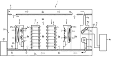
図1を参照して、ラック型空調機20は室内機21と、室外機22と、これらを接続する冷媒配管28を備えている。室内機21は、筐体21a内部に蒸発器23、送風ファン24、制御部27、冷媒配管28の往き側に電子膨張弁26を備えている。室外機22は筐体22a内部に凝縮器22c、送風ファン22d、コンプレッサ22bを主要構成として備えている。かかる構成により、凝縮器22cで凝縮した高圧冷媒液は冷媒配管28を経由して室内機21に導かれ、電子膨張弁26において低圧の気液混合状態となり、蒸発器23に至る。冷媒は蒸発器23においてホットアイル6bから吸い込まれる高温排気と熱交換して、自らは気化して冷媒蒸気となりコンプレッサ22bに戻る。一方、高温排気は冷気となって、送風ファン24によりコールドアイル側に吹き出される。
筐体21aの背面側の排気吸込部には、シャッター25が取り付けられている。シャッター25は、シャッターボックス25aと、複数のスラット25cと、左右のチェーン25cと、を主要構成として備えている。スラット25bとチェーン25cとは揺動可能に接続されており、シャッターボックス25aに内蔵される電動駆動部(図示せず)の操作により、左右のチェーン25cを揺動させて各スラットを開閉自在に構成されている。スラット25cは、閉状態において排気吸込部全体を遮蔽し、高温排気が流入しないように構成されている。
With reference to FIG. 1, the rack-type air conditioner 20 includes an
A
ラック空調システム1は以上のように構成されており、次に、図2、3を参照して、定常運転時における各サーバラック2の冷却について説明する。この場合、空調機20のシャッター25は開状態にあるものとする。空調機4に導入される室内空気は蒸発器4eにおいて熱交換して冷気となり、送風機4cにより往き側ダクト7aを介して二重床空間5cに送出される。冷気は、穴あきパネル5fを通過して、コールドアイル6aに供給され、さらに各サーバラックに導入されて、サーバ2a冷却後、高温排気となってホットアイル6bに排出される。高温排気の一部は、そのままホットアイル6bを上昇して、天井吸込口5hから天井空間5bに導かれ、戻り側ダクト7bを介して空調機4に戻される。また、高温排気の一部は、ラック型空調機20の開状態のシャッター25を介して室内機21に取り込まれ、機内の蒸発器23で冷却されて冷気となり、送風ファン24によってコールドアイル6aに吹き出され、空調機4からの冷気と混合されて、上述のように各サーバラックに吸い込まれる。以上のような室内空気の循環により、各サーバラックの冷却が行われる。
The rack air-conditioning system 1 is configured as described above, and next, cooling of each
次に図4を参照して、ラック型空調機20の高温排気吸い込み制御フローについて説明する。なお、以下の制御は、各ラック型空調機20の制御部27の指令により行われる。サーモON運転状態においては、コンプレッサ22b及び送風ファン24運転、シャッター25開の状態にある(S101)。これにより、室内機21にはホットアイル6b側から高温排気が吸い込まれ、蒸発器23で冷却された後、冷気となって送風ファン24によりコールドアイル6a側に吹き出される。
この間、サーモOFF又は冷媒系統の故障により冷媒循環が停止したときは(S102においてYES)、送風ファン24の運転が停止され(S103)、さらにシャッター25が閉止される(S105)。これにより、ホットアイル6bの高温排気の機内導入によるコールドアイル6aの急激な温度上昇を回避することができる。なお、S102においてNO、すなわちサーモON、かつ、冷媒循環状態であっても、送風ファン24が故障等により停止した場合もシャッター25が閉止される(S104、S105)。風量低下に伴い冷媒蒸発温度が下がるとドレン発生の恐れがあるが、シャッター閉止によりこれを防止することができる。その後、サーモON又は故障から復帰したときは、コンプレッサ22b及び送風ファン24運転、シャッター25開の状態に戻る(S101)
Next, a high-temperature exhaust suction control flow of the rack type air conditioner 20 will be described with reference to FIG. The following control is performed by a command from the
During this time, when the refrigerant circulation is stopped due to the thermo OFF or the failure of the refrigerant system (YES in S102), the operation of the
なお、本実施形態では電動駆動によりシャッターの開閉を行う形態としたが、バネ駆動で開閉を行う形態とすることもできる。図5はこのような形態を示すものであり、同図(a)は送風ファン24運転状態、同図(b)は同停止状態におけるスラット71の空間位置を示している。シャッター70を構成するスラット71は、本体両端に設けられた支持部材74、74に渡されたロッド74aに回動自在に軸通されている。スラット71の上部には、バネ72の一端が揺動自在に接続されている。バネ72の他端は、本体背面部材73に設けられたブラケット72aに揺動自在に接続されている。送風ファン24が運転状態のときは、同図(a)に示すように、スラット71はファン吸引力によりバネの引っ張り力に打ち勝って開状態となる。また、送風ファン24停止状態のときは、同図(b)のようにスラット71はバネの引っ張り力により閉状態となる。
さらに、バネを用いることなく、スラットの自重により開閉する形態とすることも可能である。
また、本実施形態では シャッターを排気吸い込み側に設ける例を示したが、これに限らず冷気吹き出し側、室内機内部(蒸発器の前後を問わず)に設けることも可能である。
In this embodiment, the shutter is opened / closed by electric drive, but may be opened / closed by spring drive. FIG. 5 shows such a form. FIG. 5A shows the operating state of the
Furthermore, it is also possible to adopt a form that opens and closes by the weight of the slat without using a spring.
In this embodiment, an example in which the shutter is provided on the exhaust suction side has been described. However, the present invention is not limited to this, and the shutter may be provided on the cold air blowing side or inside the indoor unit (regardless of the front and rear of the evaporator).
(第二の実施形態)
さらに、本発明の他の実施形態について説明する。本実施形態は、気流遮断手段としてシャッターを用いるのではなく、送風ファンを逆回転させてホットアイルからコールドアイル側への気流を打ち消すものである。
図6は、本実施形態に係るラック型空調機30の構成を示す図である。図7は、ラック型空調機30の高温排気吸い込み制御を示す図である。図8は、サーモOFF状態における気流方向を示す図である。
ラック型空調機30の構成が上述のラック型空調機20と異なる点は、室内機31の背面側にシャッターを備えておらず、これに替えて排気吸込部34近傍に気流検知のための超音波式風向風速センサ32を備えていることである。さらに、送風ファン33は、回転方向を正逆自在に制御可能に構成されていることである。その他の構成は上述の実施形態と同一であるので、重複説明を省略する。
(Second embodiment)
Furthermore, another embodiment of the present invention will be described. In this embodiment, a shutter is not used as the airflow blocking means, but the airflow from the hot aisle to the cold aisle is canceled by rotating the blower fan in the reverse direction.
FIG. 6 is a diagram illustrating a configuration of the rack-
The configuration of the rack-
次に図7を参照して、ラック型空調機30の高温排気吸い込み制御フローについて説明する。運転開始時、サーモONの状態(コンプレッサ22b運転)においては(S201)、送風ファン33は正方向回転で運転される(S202)。この間、サーモOFF又は冷媒系統の故障により冷媒循環が停止したときは(S203においてYES)、吸い込み部34近傍の風向風速が風向風速センサ32により計測される(S204)。センサ32の計測値が依然としてホットアイル側からコールドアイル側への気流値を示したときは(S205においてYES)、送風ファン33が逆方向回転で運転される(S206)。この場合のファン回転数は、ホットアイル側からコールドアイル側への気流を打ち消す程度の送風量に設定されている。図8は、この状態を模式的に示した図である。これにより、ホットアイル6bの高温排気を吸い込むことがなく、コールドアイルの急激な温度上昇を回避することができる。その後、サーモON状態に至ったときは(S207においてYES)、送風ファン33は正方向回転に戻される(S202)。
なお、本実施形態では風向風速センサとして超音波式センサを用いたが、熱線式、プロペラ式等、超音波式と同等の機能を有する他のセンサを用いることができる。
Next, a high-temperature exhaust suction control flow of the rack
In the present embodiment, an ultrasonic sensor is used as the wind direction and wind speed sensor, but other sensors having the same functions as the ultrasonic type, such as a hot wire type and a propeller type, can be used.
(第三の実施形態)
さらに、本発明の他の実施形態について説明する。本実施形態は、ホットアイルからコールドアイル側への気流検知手段として、両アイル間の差圧を用いるものである。
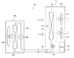
図9は、実施形態に係るラック型空調機40の構成を示す図である。ラック型空調機40の構成が上述のラック型空調機30と異なる点は、気流検知のための風向風速センサ32に替えて、室内機41の前面(コールドアイル側)及び背面(ホットアイル側)にそれぞれ圧力センサ42、43を備えていることである。両圧力センサの検出値P1、P2は、制御部27に出力されるように構成されている。その他の構成は上述の実施形態と同一であるので、重複説明を省略する。
(Third embodiment)
Furthermore, another embodiment of the present invention will be described. In the present embodiment, the differential pressure between the two aisles is used as a means for detecting the airflow from the hot aisle to the cold aisle side.
FIG. 9 is a diagram illustrating a configuration of the rack-
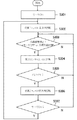
次に図10を参照して、ラック型空調機40の高温排気吸い込み制御フローについて説明する。運転開始時、サーモONの状態(コンプレッサ22b運転)においては(S301)、送風ファン44は正方向回転で運転される(S302)。本制御中において、サーモOFF又は冷媒系統の故障により冷媒循環が停止したときは(S303においてYES)、圧力センサ42、43により室内機41の前面(コールドアイル側)及び背面(ホットアイル側)の圧力P1、P2が計測される(S304)。そして、P2>P1のときは(S305においてYES)、ホットアイル側圧力が高く、高温排気がコールドアイル側に流入するおそれがあると判定する。この場合は、送風ファン44が逆回転で運転される(S306)。この場合のファン回転数は、第二の実施形態と同様にホットアイル側からコールドアイル側への気流を打ち消す程度の送風量に設定されている。その後、サーモON状態に至ったときは(S307においてYES)、送風ファン44は正方向回転に戻される(S302)。
Next, a high-temperature exhaust suction control flow of the rack
(第四の実施形態)
さらに、本発明の他の実施形態について説明する。本実施形態は、電子膨張弁の前後差圧の変化を利用してシャッター開閉を行うものである。
図11は、実施形態に係るラック型空調機の室内機51の要部構成を示す図である。ラック型空調機50の室内機51の構成が第一の実施形態に係る室内機21と異なる点は、冷媒配管58a、59b間に、電子膨張弁56と並列にピストンシリンダー59を備えていることである。また、シリンダーヘッド59aにはリンク機構59bが取り付けられており、さらに、リンク機構59bとシャッター55とは、ロッド55bを介してスラット55aを上下に揺動可能に接続されている。その他の構成は上述の実施形態と同一であるので、重複説明を省略する。
以上の構成により、サーモON状態(冷媒循環時)にはP3>P4となるため、同図(a)に示すようにシリンダーヘッド59aは上方に押され、リンク機構59bの作動によりスラット55aは開となる。一方、サーモOFF状態(冷媒循環停止時)には、P3≒P4となるため同図(a)に示すようにシリンダーヘッド59aは下方に押され、スラット55aは閉となる。このようにしてサーモOFF時にシャッター55は閉となり、高温排気の流入を遮断することができる。
(Fourth embodiment)
Furthermore, another embodiment of the present invention will be described. In this embodiment, the shutter is opened and closed by using a change in the differential pressure across the electronic expansion valve.
FIG. 11 is a diagram illustrating a main configuration of the
With the above configuration, since P3> P4 in the thermo-ON state (during refrigerant circulation), the
本発明は、熱源、冷媒、空調方式、建築構造等の種類を問わず、ラック型空調機を用いる空調システムに広く適用可能である。 The present invention is widely applicable to an air conditioning system using a rack type air conditioner regardless of the type of heat source, refrigerant, air conditioning system, building structure, and the like.
1・・・・ラック空調システム
2・・・・サーバラック
3・・・・ラック列
4・・・・アンビエント空調機
5・・・・情報通信機械室
5b・・・天井空間
5c・・・二重床空間
5d・・・床パネル
5e・・・天井パネル
5f・・・穴あきパネル
6a・・・コールドアイル
6b・・・ホットアイル
20、30、40、50・・・ラック型空調機
24、33、44、54・・・送風ファン
25、55、70・・・シャッター
25a・・・シャッターボックス
25b、55a、71・・・スラット
26、56・・・・・・電子膨張弁
32・・・超音波式風向風速センサ
42、43・・・圧力センサ
DESCRIPTION OF SYMBOLS 1 ... Rack
Claims (8)
ホットアイル側の高温排気を吸い込み、冷却空気をコールドアイル側に吹き出す送風ファンと、
所定の運転条件に連動して、高温排気の流入又は遮断を制御する排気流入制御手段と、を備え、
前記所定の運転条件が、冷媒の循環もしくは循環停止、又は、前記送風ファンの運転もしくは運転停止、のいずれか一方又は両方であり、
前記排気流入制御手段が、高温排気流入遮断用シャッターと、該シャッター開閉手段と、を含んで成る、
ことを特徴とするラック型空調機。 A rack type air conditioner used in an indoor air conditioning system in which a cold aisle and a hot aisle are formed by a plurality of server rack rows,
A blower fan that sucks in hot exhaust on the hot aisle side and blows out cooling air to the cold aisle side;
An exhaust inflow control means for controlling inflow or shut-off of high temperature exhaust in conjunction with predetermined operating conditions ,
The predetermined operating condition is one or both of circulation or suspension of refrigerant, or operation or shutdown of the blower fan,
The exhaust inflow control means includes a high-temperature exhaust inflow shut-off shutter and the shutter opening / closing means.
A rack type air conditioner characterized by that.
機内における気流の流れ方向を感知する気流感知手段と、
該気流感知手段の感知した気流方向と逆方向に、前記送風ファンを動作させる手段と、
を含んで成ることを特徴とする請求項1に記載のラック型空調機。 The exhaust inflow control means comprises:
Airflow sensing means for sensing the direction of airflow in the aircraft;
Means for operating the blower fan in a direction opposite to the airflow direction sensed by the airflow sensing means;
Rack air conditioner according to claim 1, characterized in that it comprises a.
Priority Applications (1)
| Application Number | Priority Date | Filing Date | Title |
|---|---|---|---|
| JP2008110461A JP5243092B2 (en) | 2008-04-21 | 2008-04-21 | Rack type air conditioner |
Applications Claiming Priority (1)
| Application Number | Priority Date | Filing Date | Title |
|---|---|---|---|
| JP2008110461A JP5243092B2 (en) | 2008-04-21 | 2008-04-21 | Rack type air conditioner |
Publications (2)
| Publication Number | Publication Date |
|---|---|
| JP2009257721A JP2009257721A (en) | 2009-11-05 |
| JP5243092B2 true JP5243092B2 (en) | 2013-07-24 |
Family
ID=41385366
Family Applications (1)
| Application Number | Title | Priority Date | Filing Date |
|---|---|---|---|
| JP2008110461A Active JP5243092B2 (en) | 2008-04-21 | 2008-04-21 | Rack type air conditioner |
Country Status (1)
| Country | Link |
|---|---|
| JP (1) | JP5243092B2 (en) |
Cited By (1)
| Publication number | Priority date | Publication date | Assignee | Title |
|---|---|---|---|---|
| CN106247575A (en) * | 2016-10-12 | 2016-12-21 | 安徽徽云信息科技有限公司 | A kind of machine room cooling system |
Families Citing this family (11)
| Publication number | Priority date | Publication date | Assignee | Title |
|---|---|---|---|---|
| JP5440689B2 (en) * | 2010-03-17 | 2014-03-12 | 富士電機株式会社 | Local air conditioning system and its control device |
| JP5676966B2 (en) * | 2010-08-10 | 2015-02-25 | 株式会社日立製作所 | Cooling system |
| JP5662102B2 (en) | 2010-10-25 | 2015-01-28 | 富士通株式会社 | Air conditioning system |
| JP2012093859A (en) * | 2010-10-25 | 2012-05-17 | Fujitsu Ltd | Air conditioning system |
| JP5085716B2 (en) * | 2010-11-02 | 2012-11-28 | 株式会社東芝 | Air conditioning system for server room management, server management system using the same, and air conditioning control method |
| WO2012124712A1 (en) * | 2011-03-14 | 2012-09-20 | 富士電機株式会社 | Air-conditioning system using outside air |
| JPWO2012124723A1 (en) * | 2011-03-14 | 2014-07-24 | 富士電機株式会社 | Air-conditioning system using outside air |
| JP5745337B2 (en) * | 2011-05-23 | 2015-07-08 | 三菱電機株式会社 | Air conditioning system |
| CN104165427A (en) * | 2014-08-08 | 2014-11-26 | 北京百度网讯科技有限公司 | Recovery method and device for hot channel air |
| DE102016013589A1 (en) * | 2016-11-09 | 2018-05-09 | M+W Group GmbH | drying room |
| CN113873834B (en) * | 2021-09-23 | 2023-03-24 | 浪潮通信信息系统有限公司 | Down-blowing precise air conditioner airflow control system and data center machine room |
Family Cites Families (13)
| Publication number | Priority date | Publication date | Assignee | Title |
|---|---|---|---|---|
| JPH0749314Y2 (en) * | 1991-04-05 | 1995-11-13 | 三菱電機株式会社 | air conditioner |
| JPH04359307A (en) * | 1991-06-06 | 1992-12-11 | Toshiba Corp | Cooler for electronic device |
| JP2002194825A (en) * | 2000-12-27 | 2002-07-10 | Taisei Corp | Sound insulating type ventilating hole structure and ventilation system for building |
| JP4422935B2 (en) * | 2001-11-06 | 2010-03-03 | 三菱電機株式会社 | Air conditioning system |
| JP2004169942A (en) * | 2002-11-18 | 2004-06-17 | Ntt Power & Building Facilities Inc | Air conditioning system |
| JP4360859B2 (en) * | 2003-05-29 | 2009-11-11 | 株式会社日立製作所 | Electronics |
| JP2005172309A (en) * | 2003-12-09 | 2005-06-30 | Ntt Power & Building Facilities Inc | Blower and air conditioning system for room |
| US20050237716A1 (en) * | 2004-04-21 | 2005-10-27 | International Business Machines Corporation | Air flow system and method for facilitating cooling of stacked electronics components |
| JP2006153320A (en) * | 2004-11-26 | 2006-06-15 | Sanyo Electric Co Ltd | Outdoor unit for air conditioning device |
| US7259963B2 (en) * | 2004-12-29 | 2007-08-21 | American Power Conversion Corp. | Rack height cooling |
| US7365973B2 (en) * | 2006-01-19 | 2008-04-29 | American Power Conversion Corporation | Cooling system and method |
| JP4541319B2 (en) * | 2006-04-28 | 2010-09-08 | 株式会社Sansei | cabinet |
| JP4873997B2 (en) * | 2006-05-26 | 2012-02-08 | ヤフー株式会社 | Equipment storage rack and equipment storage room air conditioning system |
-
2008
- 2008-04-21 JP JP2008110461A patent/JP5243092B2/en active Active
Cited By (1)
| Publication number | Priority date | Publication date | Assignee | Title |
|---|---|---|---|---|
| CN106247575A (en) * | 2016-10-12 | 2016-12-21 | 安徽徽云信息科技有限公司 | A kind of machine room cooling system |
Also Published As
| Publication number | Publication date |
|---|---|
| JP2009257721A (en) | 2009-11-05 |
Similar Documents
| Publication | Publication Date | Title |
|---|---|---|
| JP5243092B2 (en) | Rack type air conditioner | |
| JP5204702B2 (en) | Air conditioning system in a building with many heat generating devices | |
| JP5626365B2 (en) | Air-conditioning system using outside air, its inside air unit, outside air unit, laminate | |
| US20110259573A1 (en) | Cooling system | |
| US9317080B2 (en) | Local cooling unit and cooling system | |
| JP5243094B2 (en) | Rack air conditioning system | |
| US20130269385A1 (en) | Air conditioning system for utilizing outside air and air conditioning device thereof | |
| JP5478185B2 (en) | Air conditioning system | |
| JP5268072B2 (en) | Air conditioning control system and operation method thereof | |
| WO2012124712A1 (en) | Air-conditioning system using outside air | |
| JP5041342B2 (en) | Electronic equipment cooling system | |
| JP5669348B2 (en) | Electronic communication equipment room cooling system | |
| JP2017138060A (en) | Refrigerant natural circulation type exhaust cooling device and exhaust cooling method | |
| KR101223199B1 (en) | Airconditioing Circulation System | |
| WO2002077535A1 (en) | Air conditioner and method of installing the air conditioner | |
| JP2018066503A (en) | Data center | |
| JP2006162248A (en) | Air conditioning system | |
| JP2001041503A (en) | Case cooling system for communication base station | |
| JP4037147B2 (en) | Outdoor unit placement system | |
| WO2014175109A1 (en) | Air conditioner | |
| JP6466108B2 (en) | Control system and air conditioning system for controlling an air conditioning system | |
| KR101635448B1 (en) | A server rack | |
| KR101504261B1 (en) | Cooling tower and heat exchanging system using ventilator for basement | |
| JP6888924B2 (en) | Air conditioning system | |
| JP3982240B2 (en) | Air conditioner outdoor equipment |
Legal Events
| Date | Code | Title | Description |
|---|---|---|---|
| A621 | Written request for application examination |
Free format text: JAPANESE INTERMEDIATE CODE: A621 Effective date: 20110217 |
|
| A977 | Report on retrieval |
Free format text: JAPANESE INTERMEDIATE CODE: A971007 Effective date: 20120605 |
|
| A131 | Notification of reasons for refusal |
Free format text: JAPANESE INTERMEDIATE CODE: A131 Effective date: 20120724 |
|
| A521 | Request for written amendment filed |
Free format text: JAPANESE INTERMEDIATE CODE: A523 Effective date: 20120921 |
|
| TRDD | Decision of grant or rejection written | ||
| A01 | Written decision to grant a patent or to grant a registration (utility model) |
Free format text: JAPANESE INTERMEDIATE CODE: A01 Effective date: 20130402 |
|
| A61 | First payment of annual fees (during grant procedure) |
Free format text: JAPANESE INTERMEDIATE CODE: A61 Effective date: 20130404 |
|
| FPAY | Renewal fee payment (event date is renewal date of database) |
Free format text: PAYMENT UNTIL: 20160412 Year of fee payment: 3 |
|
| R150 | Certificate of patent or registration of utility model |
Free format text: JAPANESE INTERMEDIATE CODE: R150 Ref document number: 5243092 Country of ref document: JP Free format text: JAPANESE INTERMEDIATE CODE: R150 |
|
| R250 | Receipt of annual fees |
Free format text: JAPANESE INTERMEDIATE CODE: R250 |
|
| R250 | Receipt of annual fees |
Free format text: JAPANESE INTERMEDIATE CODE: R250 |
|
| R250 | Receipt of annual fees |
Free format text: JAPANESE INTERMEDIATE CODE: R250 |
|
| R250 | Receipt of annual fees |
Free format text: JAPANESE INTERMEDIATE CODE: R250 |
|
| R250 | Receipt of annual fees |
Free format text: JAPANESE INTERMEDIATE CODE: R250 |
|
| R250 | Receipt of annual fees |
Free format text: JAPANESE INTERMEDIATE CODE: R250 |
|
| R250 | Receipt of annual fees |
Free format text: JAPANESE INTERMEDIATE CODE: R250 |
|
| R250 | Receipt of annual fees |
Free format text: JAPANESE INTERMEDIATE CODE: R250 |
|
| R250 | Receipt of annual fees |
Free format text: JAPANESE INTERMEDIATE CODE: R250 |