JP5242503B2 - Assay apparatus and method - Google Patents
Assay apparatus and method Download PDFInfo
- Publication number
- JP5242503B2 JP5242503B2 JP2009141946A JP2009141946A JP5242503B2 JP 5242503 B2 JP5242503 B2 JP 5242503B2 JP 2009141946 A JP2009141946 A JP 2009141946A JP 2009141946 A JP2009141946 A JP 2009141946A JP 5242503 B2 JP5242503 B2 JP 5242503B2
- Authority
- JP
- Japan
- Prior art keywords
- zone
- substrate
- protrusions
- liquid
- center
- Prior art date
- Legal status (The legal status is an assumption and is not a legal conclusion. Google has not performed a legal analysis and makes no representation as to the accuracy of the status listed.)
- Active
Links
Images


Landscapes
- Automatic Analysis And Handling Materials Therefor (AREA)
Description
〔技術分野〕
本発明は、液体サンプルの分析のためのアッセイ装置に関する。
〔Technical field〕
The present invention relates to an assay device for the analysis of liquid samples.
〔背景〕
迅速で信頼ができ、かつ対費用効果の高い分析用および診断用装置、例えばケアの点で使用するための装置が、望ましい。
〔background〕
Rapid, reliable and cost-effective analytical and diagnostic devices, such as devices for use in care, are desirable.
多くのアッセイにおいて、検出抱合体と、おそらくはさらなる試薬とが装置に予め分配(predispense)されているか、または組み込まれており、一方で、使用者による試薬の別々の追加を必要とする。 In many assays, the detection conjugate and possibly additional reagents are predispensed or incorporated into the device, while requiring separate addition of reagents by the user.
普通のタイプの使い捨てアッセイ装置は、サンプルを受容するためのゾーンと、反応ゾーンと、オプションで、受容ゾーンおよび反応ゾーンのそれぞれに接続している移送またはインキュベーションゾーンとを備えている。これらのアッセイ装置は、免疫クロマトグラフィーアッセイ装置(immunochromatography assay device)として知られているか、または、単にストリップ試験と称される。 A common type of disposable assay device comprises a zone for receiving a sample, a reaction zone, and optionally a transfer or incubation zone connected to each of the receiving and reaction zones. These assay devices are known as immunochromatography assay devices or are simply referred to as strip tests.
PCT/SE03/00919は、微小流体システムに関連しており、このシステムは、基材(substrate)を備えており、かかる基材上に提供された、かかる基材から上方に突出している複数の微小ポストを備えた少なくとも1つの流動経路があり、この微小ポストと微小ポストとの間の間隔は、適用された液体サンプル中に毛管現象を誘発するのに十分なほど小さく、これにより、液体を強制的に動かす。 PCT / SE03 / 00919 relates to a microfluidic system, which includes a substrate and is provided on such a substrate and projects upwardly from such substrate. There is at least one flow path with a micropost, and the spacing between the microposts is small enough to induce capillary action in the applied liquid sample, thereby Force to move.
PCT/SE2005/000429は、液体サンプル中の分析物の検出の前に、かかるサンプル中の構成成分を分離するための装置および方法を示しており、サンプルは基材上の受容ゾーンに加えられ、かかる基材はさらに、オプションで、反応ゾーンと、受容および反応ゾーンのそれぞれに接続している移送またはインキュベーションゾーンとを備えていて、基材上に流動経路を形成しており、かかる基材は、非多孔質の基材であり、かかる流動経路の少なくとも一部は、かかる基材の表面に対して実質的に垂直な突出部の領域から構成されており、これら突出部は、かかるゾーン中のかかる液体サンプルの横向きの毛管流動が達成されるような高さ、直径、および相互間隔を有しており、分離のための手段が、サンプルを受容するためのゾーンに隣接して提供されている。 PCT / SE2005 / 000429 shows an apparatus and method for separating components in such a sample prior to detection of an analyte in a liquid sample, the sample being added to a receiving zone on the substrate, Such a substrate further optionally comprises a reaction zone and a transfer or incubation zone connected to each of the receiving and reaction zones to form a flow path on the substrate, such substrate being A non-porous substrate, wherein at least part of such flow path is composed of regions of protrusions that are substantially perpendicular to the surface of the substrate, and these protrusions are in the zone Have such a height, diameter and mutual spacing that a lateral capillary flow of such a liquid sample is achieved, and the means for separation is for receiving the sample It is provided adjacent to the zone.
PCT/SE2005/000787は、液体サンプルを取り扱うための装置に関しており、サンプルを受容するための少なくとも1つのゾーンと、移送またはインキュベーションゾーンとを備えた流動経路を具備しており、これらのゾーンは、その表面に対して実質的に垂直な突出部を有するゾーンにより接続されているか、またはこのようなゾーンを備えており、かかる装置には、かかる液体サンプルを受容する容量を備えた吸い込み口が提供されており、かかる吸い込み口は、その表面に対して実質的に垂直な突出部を有するゾーンを備えており、かかる吸い込み口は、かかる液体サンプルを受容するようにその容量を調節する外部の影響に応答するように構成されている。 PCT / SE2005 / 000787 relates to an apparatus for handling liquid samples, comprising a flow path comprising at least one zone for receiving a sample and a transfer or incubation zone, which zones are: Connected by or having a zone having a protrusion substantially perpendicular to its surface, such a device is provided with a suction port with a capacity to receive such a liquid sample Such a suction port is provided with a zone having a protrusion that is substantially perpendicular to its surface, such a suction port being external influences that adjust its capacity to receive such a liquid sample. Is configured to respond to.
PCT/SE2006/000745は、かかる少なくとも1つの流体通路を通る、またはこのような流体通路に沿う、流体移送を確立および/または維持するための吸収ゾーンに関連しており、この吸収ゾーンは、非多孔質の基材を基礎として製造されており、かかる表面に対して実質的に直角な突出部を有しており、かかる突出部は、かかるゾーン中のかかる流体の横向きの毛管流動が達成されるような高さ、直径、および突出部と突出部との間の距離(distance or distances)を有している。 PCT / SE2006 / 000745 relates to an absorption zone for establishing and / or maintaining fluid transport through or along such at least one fluid passage, Manufactured on the basis of a porous substrate and has protrusions that are substantially perpendicular to such surfaces, such protrusions achieve lateral capillary flow of such fluids in such zones. Height, diameter, and distance or distances between the protrusions.
先行技術に従う突出部を備えるアッセイ装置は満足に働くが、例えば、装置に適用される物質の溶解の制御に関して、さらなる改善の余地がある。 While assay devices with protrusions according to the prior art work satisfactorily, there is room for further improvement, for example with respect to controlling the dissolution of substances applied to the device.
〔発明の概要〕
本発明のある一つの目的は、予め分配された物質の溶解の制御がさらに改善された装置を提供することである。液体サンプルの分析のための分析装置が入手可能になり、かかる装置は、基材を備え、かかる基材は少なくとも部分的に、かかる基材の表面に対して実質的に垂直な突出部を有し、これら突出部は、かかる液体サンプルの横向きの毛管流動が達成されるような高さ(H1)、直径(D1)、および中心から中心までの距離(x1,y1)を有し、かかる基材は、かかる基材の表面に対して実質的に垂直な突出部を備えた、少なくとも1つの基材ゾーンを備えており、この突出部は、かかる液体サンプルの横向きの毛管流動が達成されるような高さ(H2)、直径(D2)、および中心から中心までの距離(x2,y2)を有しており、少なくとも1つの物質が、かかる少なくとも1つの基材ゾーン中の突出部と突出部との間に少なくとも部分的に適用される。
[Summary of the Invention]
One object of the present invention is to provide an apparatus with further improved control of dissolution of pre-dispensed material. Analytical devices for the analysis of liquid samples become available, such devices comprising a substrate, such a substrate having at least partly a protrusion substantially perpendicular to the surface of the substrate. These protrusions have a height (H1), a diameter (D1), and a center-to-center distance (x1, y1) such that a lateral capillary flow of such a liquid sample is achieved. The material comprises at least one substrate zone with a protrusion that is substantially perpendicular to the surface of such substrate, which protrusion achieves lateral capillary flow of such a liquid sample. Having a height (H2), a diameter (D2), and a center-to-center distance (x2, y2) such that at least one substance has protrusions and protrusions in such at least one substrate zone At least part between the parts It is applied to.
本発明のさらなる側面および実施形態が、参照により本明細書中に組み込まれる付属の請求項で定義されている。 Further aspects and embodiments of the invention are defined in the appended claims, which are incorporated herein by reference.
本発明は、下記の記載、実施例、および添付の図面において、より徹底した詳細が記載されるであろう。 The invention will be described in more thorough details in the following description, examples, and accompanying drawings.
〔定義〕
本装置および本方法が記載される前に、この発明は、本明細書中で開示された特定の構造、方法ステップ、および材料に限定されるものではなく、構造、ステップ、および材料はいくらか変わってもよいということが理解されるべきである。また、本発明の範囲は付属の請求項およびその等価物によってのみ限定され得るので、本明細書中で用いられる専門用語は、特定の実施形態を記述することを目的として使用されるだけであって、限定することを意図するものではないことも理解されるべきである。この明細書および付属の請求項において使用される、単数形「ある(a)」、「ある(an)」、「その(the)」は、その文脈が他に明確に断らない限り、複数の指示対象を含むことも述べておかなければならない。それ故、例えば、反応混合物が「抗体(an antibody)」を含有するとの言及には、2つまたはそれ以上の抗体の混合物を含める。
[Definition]
Before the present apparatus and method are described, the present invention is not limited to the specific structures, method steps, and materials disclosed herein, and the structures, steps, and materials may vary somewhat. It should be understood that it may be. Also, since the scope of the present invention may be limited only by the appended claims and their equivalents, the terminology used herein is for the purpose of describing particular embodiments only. It should also be understood that it is not intended to be limiting. As used in this specification and the appended claims, the singular forms “a”, “an”, “the”, and plural terms unless the context clearly dictates otherwise. It must also be mentioned that the target object is included. Thus, for example, reference to a reaction mixture containing “an antibody” includes a mixture of two or more antibodies.
用語「約(about)」は、数値の文脈において使用される場合には、当業者によく知られていて許容可能である、精度の隔たりを示している。かかる隔たりは、±10%、または好ましくは±5%とすることができる。 The term “about”, when used in the numerical context, indicates a gap in accuracy that is well known and acceptable to those skilled in the art. Such separation can be ± 10%, or preferably ± 5%.
装置および方法を記述および請求する際に、下記の専門用語は、ここで詳しく述べられる定義に従って使用されるであろう。 In describing and claiming the apparatus and method, the following terminology will be used in accordance with the definitions detailed herein.
請求項および説明の全体を通して使用される用語「分析」は、少なくとも1つの分析物が決定されるプロセスを意味している。 The term “analysis” as used throughout the claims and description refers to the process by which at least one analyte is determined.
請求項および説明の全体を通して使用される用語「分析装置」は、装置であって、その装置の助けによって分析が実施されることができる装置を意味している。 The term “analytical device” as used throughout the claims and the description means a device in which an analysis can be carried out with the help of that device.
請求項および説明の全体を通して使用される用語「分析物」は、物質、または化学的もしくは生物学的成分であって、それらの1つまたはそれ以上の性質が分析手順において決定される物質、または化学的もしくは生物学的成分を意味している。多くの場合、分析物または構成成分そのものは、測定されることができないが、分析物の測定可能な性質は、測定されることができる。例えば、分析物の濃度を測定することができる。 The term “analyte” as used throughout the claims and description is a substance, or a chemical or biological component whose one or more properties are determined in an analytical procedure, or Means a chemical or biological component. In many cases, the analyte or component itself cannot be measured, but the measurable nature of the analyte can be measured. For example, the concentration of the analyte can be measured.
請求項および説明の全体を通して使用される用語「毛管流動(capillary flow)」は、主に毛管力(capillary force)で誘発された流動を意味している。 The term “capillary flow” as used throughout the claims and the description means a flow induced primarily by a capillary force.
請求項および説明の全体を通して使用される用語「ケーシング」は、基材の一部または全体を包囲する要素を意味している。 The term “casing” as used throughout the claims and the description means an element that surrounds part or all of the substrate.
請求項および説明の全体を通して使用される用語「中心から中心までの距離(center-to-center distance)」は、隣り合う突出部の間の距離を意味しており、突出部の中心から隣接する突出部の中心までが測定される。平面状の基材については、中心から中心までの距離は、基材平面の直交座標系における、x方向およびy方向の両方が測定される。 The term “center-to-center distance” as used throughout the claims and the description means the distance between adjacent protrusions and is adjacent from the center of the protrusion. The center of the protrusion is measured. For a planar substrate, the distance from the center to the center is measured in both the x and y directions in the orthogonal coordinate system of the substrate plane.
請求項および説明の全体を通して使用される用語「突出部の中心」は、基材の表面に平行な平面における、突出部の高さの半分で獲得された突出部の無限小薄切片についての重心を意味している。湾曲した基材については、この平面は、突出部の周りの十分に小さい周囲においては、基材の表面に平行である。 The term “projection center” as used throughout the claims and description is the center of gravity for an infinitesimal section of the projection obtained at half the height of the projection in a plane parallel to the surface of the substrate. Means. For curved substrates, this plane is parallel to the surface of the substrate at a sufficiently small circumference around the protrusion.
請求項および説明の全体を通して使用される用語「接続ゾーン(connecting zone)」は、少なくとも2つの他のゾーンの間の流体接続を確立するゾーンを意味している。 The term “connecting zone” as used throughout the claims and the description means a zone that establishes a fluid connection between at least two other zones.
請求項および説明の全体を通して使用される用語「検出可能な基」は、基材上に存在する時に検出されることができる分子または原子のあらゆる配列を意味している。 The term “detectable group” as used throughout the claims and description means any arrangement of molecules or atoms that can be detected when present on a substrate.
請求項および説明の全体を通して使用される用語「流体接続(fluid connection)」は、流体が移送されることができる接続を意味している。 The term “fluid connection” as used throughout the claims and the description means a connection through which fluid can be transported.
請求項および説明の全体を通して使用される用語「サンプル」は、分析されるべき混合物または溶液を意味している。 The term “sample” as used throughout the claims and the description means the mixture or solution to be analyzed.
請求項および説明の全体を通して使用される用語「物質」は、あらゆる純粋な化学的もしくは生物学的実体、または、少なくとも1つの化学的もしくは生物学的実体を含むあらゆる混合物または溶液を意味している。 The term “substance” as used throughout the claims and the description means any pure chemical or biological entity, or any mixture or solution containing at least one chemical or biological entity. .
〔詳細な説明〕
第一の側面において、液体サンプルの分析のための分析装置が提供され、かかる装置は、基材を備えており、かかる基材は少なくとも一部に、かかる基材の表面に対して実質的に垂直な突出部を有しており、これら突出部は、かかる液体サンプルの横向きの毛管流動が達成されるような高さ、直径、および中心から中心までの距離を有しており、かかる基材は、かかる基材の表面に対して実質的に垂直な突出部を備えた、少なくとも1つの基材ゾーンを備えており、これら突出部は、かかる液体サンプルの横向きの毛管流動が達成されるような高さ(H2)、直径(D2)、および中心から中心までの距離(x2,y2)を有しており、少なくとも1つの物質が、かかる少なくとも1つの基材ゾーン中の突出部と突出部との間に少なくとも部分的に適用される。
[Detailed explanation]
In a first aspect, an analytical device for the analysis of a liquid sample is provided, the device comprising a substrate, such substrate being at least partly substantially with respect to the surface of the substrate. Such protrusions having a height, a diameter, and a center-to-center distance such that a lateral capillary flow of such a liquid sample is achieved. Comprises at least one substrate zone with protrusions substantially perpendicular to the surface of such a substrate, such that the protrusions achieve lateral capillary flow of such a liquid sample. Having a height (H2), a diameter (D2), and a center-to-center distance (x2, y2), wherein at least one substance has protrusions and protrusions in such at least one substrate zone At least part between It is applicable.
液体サンプルが基材に加えられると、表面上の突出部に起因した毛管力により流動が生み出される。ここで、突出部は、高さ(H1)、直径(D1)、および中心から中心までの距離(x1,y1)を有する。また、突出部で覆われた少なくとも1つのゾーンもあり、ここで、突出部は、高さ(H1)、直径(D1)、および中心から中心までの距離(x1,y1)を有する基材上の他の突出部と比較して、異なる高さ(H2)、直径(D2)、または中心から中心までの距離(x2,y2)を有する。ある一つの実施形態において、性質、すなわち、高さ、直径、および中心から中心までの距離のうちの少なくとも1つは、ゾーンによって異なる。他の実施形態においては、高さ、直径、および中心から中心までの距離が異なる。さらなる実施形態においては、直径および中心から中心までの距離が異なる。ある一つの実施形態において、H1およびH2は異なる。ある一つの実施形態において、D1およびD2は異なる。ある一つの実施形態において、x1およびx2は異なる。ある一つの実施形態において、y1およびy2は異なる。さらなる実施形態において、パラメータH、D、x、およびyのうちのいくつかが異なる。ある一つの実施形態において、全てのパラメータH、D、x、およびyが、物質の少なくとも2つのゾーンについて同じである。ある一つの実施形態において、全てのパラメータH、D、x、およびyが、装置の全体について同じである。 When a liquid sample is added to the substrate, flow is created by capillary forces due to protrusions on the surface. Here, the protrusion has a height (H1), a diameter (D1), and a center-to-center distance (x1, y1). There is also at least one zone covered with a protrusion, where the protrusion is on a substrate having a height (H1), a diameter (D1), and a center-to-center distance (x1, y1). Compared to the other protrusions, it has a different height (H2), diameter (D2), or center-to-center distance (x2, y2). In one embodiment, at least one of the properties, ie height, diameter, and center-to-center distance, varies from zone to zone. In other embodiments, the height, diameter, and center-to-center distance are different. In further embodiments, the diameter and center-to-center distance are different. In one embodiment, H1 and H2 are different. In one embodiment, D1 and D2 are different. In one embodiment, x1 and x2 are different. In one embodiment, y1 and y2 are different. In further embodiments, some of the parameters H, D, x, and y are different. In one embodiment, all parameters H, D, x, and y are the same for at least two zones of the material. In one embodiment, all parameters H, D, x, and y are the same for the entire device.
少なくとも1つの物質が、基材上の突出部と突出部との間に適用される。ある一つの実施形態において、物質は、少なくとも1つの基材ゾーン内で全体的に適用される。代替の実施形態において、少なくとも1つの物質が、少なくとも1つの基材ゾーンの中と、少なくとも1つの基材ゾーンの外側との両方に適用される。 At least one substance is applied between the protrusions on the substrate. In one embodiment, the material is applied entirely within at least one substrate zone. In an alternative embodiment, at least one substance is applied both inside the at least one substrate zone and outside the at least one substrate zone.
ある一つの実施形態において、基材ゾーン中の突出部は、異なる高さ(H2)、直径(D2)、または中心から中心までの距離(x2,y2)を有しており、基材ゾーンが、周囲とは異なる外観を有するようになっている。このことは、物質が適用されるべきゾーンが容易にヒトの目または自動化された装置により同定されることができるため、装置が製品である場合の利点である。 In one embodiment, the protrusions in the substrate zone have different heights (H2), diameters (D2), or center-to-center distances (x2, y2), where the substrate zone , So that it has a different appearance from the surroundings. This is an advantage when the device is a product, since the zone to which the substance is to be applied can easily be identified by the human eye or an automated device.
ある一つの実施形態において、基材ゾーン中の突出部は、異なる高さ(H2)、直径(D2)、または中心から中心までの距離(x2,y2)を有しており、基材ゾーンが、周囲と比較して、溶液中の物質に対して異なる毛管力を発揮するようになっている。このことは、溶液または懸濁液中の物質の添加を促進する。ある一つの実施形態において、基材ゾーンにより発揮される毛管力は、周囲についてよりも高く、これにより、溶液または懸濁液中の物質が、より容易に基材ゾーンにのみ適用されることができる。ある一つの実施形態において、適用されるべき物質は、溶媒中に溶解されるか、または懸濁されて、基材に適用される。ある一つの実施形態において、溶媒は蒸発され、これにより、物質が基材上に残る。このことは、中に物質が適用される良好に画定された領域を生み出す利点を有している。適用された物質の境界はくっきりと鮮明である。 In one embodiment, the protrusions in the substrate zone have different heights (H2), diameters (D2), or center-to-center distances (x2, y2), where the substrate zone Compared with the surroundings, it exerts a different capillary force on the substance in the solution. This facilitates the addition of the substance in solution or suspension. In one embodiment, the capillary force exerted by the substrate zone is higher than for the surroundings, so that the substance in solution or suspension is more easily applied only to the substrate zone. it can. In one embodiment, the substance to be applied is dissolved or suspended in a solvent and applied to the substrate. In one embodiment, the solvent is evaporated, thereby leaving the material on the substrate. This has the advantage of creating a well-defined area in which the substance is applied. The boundaries of the applied material are clear and crisp.
ある一つの実施形態において、物質は、基材ゾーンの突出部と突出部との間の嵩(volume)に適用される。物質が基材に適用されると、基材ゾーンの突出部から発揮される毛管力が、ある一つの形態においては、溶液または懸濁液中の物質で基材ゾーンの突出部と突出部との間の嵩の本質的に全体をいっぱいにさせる。 In one embodiment, the material is applied to the volume between the protrusions of the substrate zone. When the substance is applied to the substrate, the capillary force exerted from the protrusions of the substrate zone is, in one form, the substance in the solution or suspension with the protrusions and protrusions of the substrate zone. The bulk between the essentially fills the whole.
ある一つの実施形態において、基材ゾーンの突出部は、突出部により発揮される毛管力が基材ゾーンに対してかかる物質を添加するのを促進するような、高さ(H2)、直径(D2)、および中心から中心までの距離(x2,y2)を有する。 In one embodiment, the protrusion of the substrate zone has a height (H2), a diameter (such that the capillary force exerted by the protrusion facilitates the addition of such substances to the substrate zone. D2) and a center-to-center distance (x2, y2).
ある一つの実施形態において、物質は、本質的に純粋な物質である。他の実施形態においては、少なくとも1つの物質は、2種またはそれ以上の物質の混合物である。 In one embodiment, the material is essentially pure material. In other embodiments, the at least one substance is a mixture of two or more substances.
基材上に適用されることができる物質の例としては、限定されるものではないが、抗体、DNA、RNA、アプタマー、サンプル中の特定の分析物に向けられた抗体、断片化された抗体(fragmented antibodies)、抗体断片、合成結合剤、化学的結合剤、レセプター、リガンド、アフィボディ(affibodies)、細胞、細胞小器官、ポリペプチド、ペプチド、酵素、単クローン抗体、多クローン性抗体、ファージディスプレイタンパク質、IgG免疫グロブリン、化学的リガンド、およびこれらの組み合せを含む。 Examples of substances that can be applied on a substrate include, but are not limited to, antibodies, DNA, RNA, aptamers, antibodies directed to specific analytes in a sample, fragmented antibodies (Fragmented antibodies), antibody fragments, synthetic binders, chemical binders, receptors, ligands, affibodies, cells, organelles, polypeptides, peptides, enzymes, monoclonal antibodies, polyclonal antibodies, phages Includes display proteins, IgG immunoglobulins, chemical ligands, and combinations thereof.
ある一つの実施形態において、基材に適用されるべき物質は、少なくとも1つのさらなる添加物を含む。さらなる添加物の例としては、限定されるものではないが、糖、ポリマー、洗浄剤、表面活性剤、カチオン性表面活性剤、非イオン性表面活性剤、アニオン性表面活性剤、塩、および脂質、またはこれらのいずれかの組み合わせを含む。 In one embodiment, the substance to be applied to the substrate comprises at least one further additive. Examples of additional additives include, but are not limited to, sugars, polymers, detergents, surfactants, cationic surfactants, nonionic surfactants, anionic surfactants, salts, and lipids Or a combination of any of these.
ある一つの実施形態において、基材に少なくとも1つのさらなる物質が加えられ、ここで、その物質とは、糖、ポリマー、洗浄剤、表面活性剤、カチオン性表面活性剤、非イオン性表面活性剤、アニオン性表面活性剤、塩、および脂質から選択される少なくとも1つの物質である。 In one embodiment, at least one additional substance is added to the substrate, where the substance is a sugar, polymer, detergent, surfactant, cationic surfactant, nonionic surfactant , At least one substance selected from anionic surfactants, salts, and lipids.
ある一つの実施形態において、基材は下記の順序どおり、流体接続状態で、少なくとも1つのサンプル添加ゾーン、少なくとも1つの接続ゾーン、および少なくとも1つの受容ゾーンをさらに備え、かかる接続ゾーンは、少なくとも1つの反応ゾーンを備え、かかる少なくとも1つの基材ゾーンは、かかるサンプル添加ゾーンと反応ゾーンとの間にある。ある一つの実施形態において、少なくとも、接続ゾーンの一部は、横向きの毛管流動が達成されるように突出部により覆われている。 In one embodiment, the substrate further comprises at least one sample addition zone, at least one connection zone, and at least one receiving zone, in fluid connection, in the following order: With one reaction zone, such at least one substrate zone being between such sample addition zone and reaction zone. In one embodiment, at least a portion of the connection zone is covered by protrusions so that lateral capillary flow is achieved.
ある一つの実施形態において、少なくとも1つのゾーンは、突出部の高さ(H)、直径(D)、および中心から中心までの距離(x,y)のうちの少なくとも1つが、周囲の突出部がサンプル液体、次にゾーンに対してより低い毛管力を発揮するように、異なっている領域により取り囲まれている。ある一つの実施形態において、かかるゾーンは、反応ゾーンおよび基材ゾーンから選択される少なくとも1つのゾーンである。ある一つの実施形態において、かかるゾーンは、基材ゾーンである。ある一つの実施形態において、ゾーンを取り囲んでいる領域における中心から中心までの距離は、ゾーン内のものと比較してより大きい。 In one embodiment, the at least one zone has at least one of a protrusion height (H), a diameter (D), and a center-to-center distance (x, y) that is a peripheral protrusion. Are surrounded by different regions so as to exert a lower capillary force on the sample liquid and then on the zone. In one embodiment, such a zone is at least one zone selected from a reaction zone and a substrate zone. In one embodiment, such a zone is a substrate zone. In one embodiment, the center-to-center distance in the region surrounding the zone is greater than in the zone.
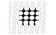
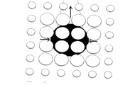
ある一つの実施形態において、基材ゾーンおよび反応ゾーンの少なくとも1つを、全く突出部を備えていない領域が取り囲んでいる。突出部を備えていない領域が基材ゾーンを取り囲んでいる、ある一つの実施形態が図6に示されている。ある一つの実施形態において、突出部を備えていない周囲領域は、15〜100μmの幅である。他の実施形態において、突出部を備えていない周囲領域は、20〜40μmの幅である。さらなる実施形態において、突出部を備えていない周囲領域は、25〜35μmの幅である。この幅は、基材ゾーンに加えられる基材の粘度、および基材ゾーンを取り囲む表面の親水性に依存する。 In one embodiment, at least one of the substrate zone and the reaction zone is surrounded by a region having no protrusions. One embodiment is shown in FIG. 6 in which an area without protrusions surrounds the substrate zone. In one embodiment, the surrounding area without protrusions is 15-100 μm wide. In other embodiments, the surrounding area without the protrusions is 20-40 μm wide. In a further embodiment, the surrounding area without protrusions is 25-35 μm wide. This width depends on the viscosity of the substrate applied to the substrate zone and the hydrophilicity of the surface surrounding the substrate zone.
異なる性質を有する周囲領域を備えたゾーンの利点としては、物質がゾーンの外に流れ出ることなく、ゾーンに物質を適用することができることを含む。それ故、再現性が良く、よく境界が画定されるように、ゾーンに物質を適用することができる。 Advantages of zones with surrounding areas having different properties include that the material can be applied to the zone without flowing out of the zone. Therefore, the material can be applied to the zone so that it is reproducible and well defined.
ある一つの実施形態において、接続ゾーンの全体が、横向きの毛管流動が達成されるように突出部により覆われている。ある一つの実施形態において、少なくとも、サンプル添加ゾーンの一部、接続ゾーン、および受容ゾーンが、横向きの毛管流動が達成されるように突出部により覆われている。他の実施形態において、サンプル添加ゾーン、接続ゾーン、および受容ゾーンの全体が、横向きの毛管流動が達成されるように突出部により覆われている。 In one embodiment, the entire connection zone is covered by protrusions so that lateral capillary flow is achieved. In one embodiment, at least a portion of the sample addition zone, the connection zone, and the receiving zone are covered with protrusions so that lateral capillary flow is achieved. In other embodiments, the entire sample addition zone, connection zone, and receiving zone are covered by protrusions so that lateral capillary flow is achieved.
ある一つの実施形態において、分析装置および基材は、サンプル添加ゾーンにサンプルを加えることができるようになっている。突出部により誘発された毛管流動に起因して、横向きの流動が生み出され、少なくともサンプルの一部が、高さ(H2)、直径(D2)、および中心から中心までの距離(x2,y2)を有する突出部がある、基材上の少なくとも1つの基材ゾーンに到達する。ある一つの実施形態において、少なくとも1つの基材ゾーン内、および/または少なくとも1つの基材ゾーンの近くに適用された物質は、少なくとも1つの基材ゾーンを通ってサンプルが流動することにより徐々に溶解される。その後、液体サンプルは、反応ゾーンに到達する。ある一つの実施形態において、測定は反応ゾーンでなされる。測定技術の例として、限定されるものではないが、蛍光、および化学発光の検出を含む。当業者であれば、オプションでいくつかの異なる波長における、光の吸収、および放射された光の検出といったその他の検出原理もまた、使用されることができることを認める。ある一つの実施形態において、サンプルは、受容ゾーンへと続き、受容ゾーンが液体サンプルを受容する。流動は、液体サンプルが無くなるか、または受容ゾーンがサンプル液体でいっぱいになるまで続く。 In one embodiment, the analytical device and the substrate are adapted to add a sample to the sample addition zone. Due to the capillary flow induced by the protrusion, a lateral flow is created and at least a portion of the sample is at a height (H2), a diameter (D2), and a center-to-center distance (x2, y2). The at least one substrate zone on the substrate is reached with a protrusion having In one embodiment, the material applied in and / or near the at least one substrate zone is gradually increased by the sample flowing through the at least one substrate zone. Dissolved. The liquid sample then reaches the reaction zone. In one embodiment, the measurement is made in the reaction zone. Examples of measurement techniques include, but are not limited to, detection of fluorescence and chemiluminescence. One skilled in the art will recognize that other detection principles, such as absorption of light and detection of emitted light, optionally at several different wavelengths can also be used. In one embodiment, the sample continues to the receiving zone, which receives the liquid sample. The flow continues until there is no liquid sample or the receiving zone is full of sample liquid.
ある一つの実施形態において、サンプル液体は過剰である。物質の全てが溶解されると、反応ゾーンおよび装置のその他の部分が洗浄されて、遊離しているか、または緩く結合している物質が洗い流されるように、過剰のサンプル液体の一部が使用される。 In one embodiment, the sample liquid is in excess. When all of the material has been dissolved, some of the excess sample liquid is used so that the reaction zone and other parts of the instrument are washed away, free or loosely bound material is washed away. The
ある一つの実施形態においては、いくつかの受容ゾーンがある。 In one embodiment, there are several receiving zones.
少なくとも1つの基材ゾーンに適用される少なくとも1つの物質は、ある一つの実施形態においては基材表面上に適用される。ある一つの実施形態において、物質は、突出部と突出部との間に適用される。ある一つの実施形態において、適用された物質の厚みは、乾燥した状態で、突出部の高さに本質的に一致する。代替の実施形態においては、適用された物質の厚みは、乾燥した状態で、突出部の高さよりも低い。ある一つの実施形態において、適用された物質の厚みは、乾燥した状態で、突出部よりも高い。 The at least one substance applied to the at least one substrate zone is applied on the substrate surface in one embodiment. In one embodiment, the substance is applied between the protrusions. In one embodiment, the thickness of the applied material essentially matches the height of the protrusions when dry. In an alternative embodiment, the thickness of the applied material is dry and less than the height of the protrusion. In one embodiment, the thickness of the applied material is higher than the protrusions in the dry state.
ある一つの実施形態において、少なくとも1つの物質は、乾燥した状態の物質が、突出部の高さ(H2)の半分のレベルまでの嵩を満たすように、かかる少なくとも1つの基材ゾーン中の突出部と突出部との間の嵩に適用される。 In one embodiment, the at least one substance is a protrusion in such at least one substrate zone such that the dried substance fills the volume up to half the height of the protrusion (H2). Applies to the bulk between the part and the protrusion.
代替の実施形態において、少なくとも1つの物質は、乾燥した状態の物質が、突出部と本質的に同じ高さ(H2)までの嵩を満たすように、かかる少なくとも1つの基材ゾーン中の突出部と突出部との間の嵩に適用される。 In an alternative embodiment, the at least one material is a protrusion in such at least one substrate zone such that the dried material fills the bulk up to essentially the same height (H2) as the protrusion. And applied to the bulk between the protrusions.
さらなる実施形態において、少なくとも1つの物質は、乾燥した状態の物質が、かかる少なくとも1つの物質の上部に液体流動が本質的に起きないようなレベルまでの嵩を満たすように、かかる少なくとも1つの基材ゾーン中の突出部と突出部との間の嵩に適用される。 In a further embodiment, the at least one substance comprises at least one group such that the dried substance fills a volume to such a level that essentially no liquid flow occurs on top of such at least one substance. Applies to the bulk between the protrusions in the material zone.
ある一つの実施形態において、基材ゾーンの突出部と突出部との間の嵩は、適用されるべき物質の量が、乾燥した状態で所望のレベルまで満たすように、調節される。 In one embodiment, the bulk between the protrusions of the substrate zone is adjusted so that the amount of material to be applied is dry and meets the desired level.
ある一つの実施形態において、物質は、溶液中に適用され、溶媒が蒸発するように乾燥される。ある一つの実施形態において、溶媒は水である。溶媒が蒸発すると、残りの物質は、乾燥した状態の物質と呼ばれる。 In one embodiment, the material is applied in solution and dried so that the solvent evaporates. In one embodiment, the solvent is water. When the solvent evaporates, the remaining material is called dry material.
適用された物質の上部において液体が流動しないか、または本質的に流動しない実施形態において、適用された物質の溶解は、側面から生じて、上部からは生じない。このことは、制御された溶解を与える。溶解は、液体サンプルが適用された物質の上でも流動する実施形態と比較して、より長期間の間、より制御された方法で生じる。 In embodiments where the liquid does not flow or essentially does not flow at the top of the applied material, dissolution of the applied material occurs from the side and not from the top. This gives controlled dissolution. Dissolution occurs in a more controlled manner for a longer period of time compared to embodiments where the liquid sample also flows over the applied material.
ある一つの実施形態において、適用された物質の上部では、液体が流動しない。代替の実施形態において、液体の極一部のみが、適用された物質の上部を流動し、例えば、液体のそのような一部の例とは、限定されるものではないが、0.1wt%、1wt%、5wt%、および10wt%を含む。ある一つの実施形態において、液体の1wt%未満が、適用された物質の上部を流動する。他の実施形態において、液体の10wt%未満が、適用された物質の上部を流動する。 In one embodiment, no liquid flows on top of the applied material. In an alternative embodiment, only a small portion of the liquid flows over the applied material, for example, but not limited to, 0.1 wt% of such a portion of the liquid. 1 wt%, 5 wt%, and 10 wt%. In one embodiment, less than 1 wt% of the liquid flows over the applied material. In other embodiments, less than 10 wt% of the liquid flows over the applied material.
例えば、適用された物質の上部を液体が本質的に流動しない実施形態において、突出部の直径および中心から中心までの距離を調節することにより、液体への適用された物質の溶解を制御することができる。 For example, in embodiments where the liquid does not essentially flow over the top of the applied material, controlling the dissolution of the applied material in the liquid by adjusting the diameter of the protrusion and the center-to-center distance. Can do.
ある一つの実施形態において、適用された物質の全ての構成成分は、液体サンプルにより溶解される。代替の実施形態においては、全ての適用された物質が、液体サンプルにより溶解されるわけではない。 In one embodiment, all components of the applied material are dissolved by the liquid sample. In an alternative embodiment, not all applied material is lysed by the liquid sample.
物質が適用されたゾーン中、および物質が適用されたゾーンの外側の突出部の高さ、直径、および中心から中心までの距離を調節することにより、適用された物質の所望の溶解が所望の速度で生じるように横向きの毛管流動を制御することができる。 By adjusting the height, diameter, and center-to-center distance of the protrusions in the zone to which the substance is applied and outside the zone to which the substance is applied, the desired dissolution of the applied substance is desired. Lateral capillary flow can be controlled to occur at speed.
ある一つの実施形態において、高さ(H1、H2)、直径(D1、D2)、および中心から中心までの距離(x1、x2,y1、y2)は、かかる少なくとも1つの物質が、かかる基材ゾーンを通って流動する液体の流れに徐々に溶解されるように構成される。 In one embodiment, the height (H1, H2), diameter (D1, D2), and center-to-center distance (x1, x2, y1, y2) are such that at least one substance is such a substrate. It is configured to be gradually dissolved in a liquid stream flowing through the zone.
本発明は、突出部の2つの異なる高さ、直径、および中心から中心までの距離に限定されるものではない。さらなるゾーンであって、各ゾーンが、高さ、直径、および中心から中心までの距離を有し、これらパラメータの少なくとも1つが、他のゾーンと比較して異なる、さらなるゾーンを備えた実施形態が提供される。 The present invention is not limited to two different heights, diameters, and center-to-center distances of the protrusions. Embodiments comprising further zones, each zone having a height, a diameter, and a center-to-center distance, wherein at least one of these parameters is different compared to the other zones Provided.
分析装置が少なくとも1つの追加のゾーンnを備え、各追加のゾーンnは、かかる基材の表面に対して実質的に垂直な突出部を備え、これら突出部は、横向きの毛管流動が生み出されるような高さ(Hn)、直径(Dn)、および中心から中心までの距離(xn,yn)を有する実施形態が提供される。n個の別個のゾーンを有し、各ゾーンが、高さ(Hn)、直径(Dn)、および中心から中心までの距離(xn,yn)を有する突出部を備え、nが自然数である基材が提供される。nは、1、2、3、4、5、6…である。 The analytical device comprises at least one additional zone n, each additional zone n comprising protrusions that are substantially perpendicular to the surface of such a substrate, which protrusions produce transverse capillary flow. Embodiments having such a height (H n ), diameter (D n ), and center-to-center distance (x n , y n ) are provided. having n distinct zones, each zone comprising a protrusion having a height (H n ), a diameter (D n ), and a center-to-center distance (x n , y n ), where n is Substrates that are natural numbers are provided. n is 1, 2, 3, 4, 5, 6.
ある一つの実施形態において、n個のゾーンのうちの少なくとも1つに少なくとも一つの物質が適用される。 In one embodiment, at least one substance is applied to at least one of the n zones.
ある一つの実施形態においては、基材ゾーンがあり、この基材ゾーンは、かかる基材の表面に対して実質的に垂直な突出部を備え、これら突出部は、かかる液体サンプルの横向きの毛管流動が達成されるような高さ、直径、および中心から中心までの距離を有し、基材ゾーン中のこの高さ、直径、および中心から中心までの距離は、基材ゾーンの外側とは異なる。ある一つの実施形態において、突出部の高さ、直径、および中心から中心までの距離は、基材ゾーン内で変化する。 In one embodiment, there is a substrate zone, the substrate zone comprising protrusions that are substantially perpendicular to the surface of such substrate, the protrusions being transverse capillaries of such a liquid sample. The height, diameter, and center-to-center distance such that flow is achieved, and this height, diameter, and center-to-center distance in the substrate zone is defined as outside the substrate zone. Different. In one embodiment, the protrusion height, diameter, and center-to-center distance vary within the substrate zone.
ある一つの実施形態においては、適用された物質を含む少なくとも2つのゾーンがあり、これらゾーンは、同心円の形状を有する。ある一つの実施形態において、外側部分は、少なくとも1つの適用された物質を含み、内側部分は、少なくとも1つの他の適用された物質を含む。まず、外側の物質が溶解され、その後、内側の物質が溶解される。これにより、溶解を制御するさらなる可能性が提供される。また、いくつかの物質を順序どおりか、または一緒に溶解する可能性も提供される。ある一つの実施形態において、1つ以上の物質を順序どおり溶解する可能性が提供される。その他の実施形態において、その他の形状の、適用された物質を備えた異なるゾーンもまた、提供される。ある一つの実施形態において、少なくとも1つのゾーンがあり、このゾーンは、まず、サンプル液体に接触し、そのゾーン中の物質の画分または全てが溶解すると、サンプル液体が、異なる物質を含む他のゾーンに接触する。これにより、所定の期間の後で、サンプル液体中の物質の溶解を開始させることができる。 In one embodiment, there are at least two zones containing the applied material, and these zones have a concentric shape. In one embodiment, the outer portion includes at least one applied material and the inner portion includes at least one other applied material. First, the outer material is dissolved, and then the inner material is dissolved. This provides a further possibility to control dissolution. It also provides the possibility to dissolve several substances in order or together. In one embodiment, the possibility of dissolving one or more substances in sequence is provided. In other embodiments, different shaped, different zones with applied material are also provided. In one embodiment, there is at least one zone that is first contacted with the sample liquid and when the fraction or all of the substance in that zone dissolves, the sample liquid contains other substances that contain different substances. Touch the zone. Thereby, the dissolution of the substance in the sample liquid can be started after a predetermined period.
このように、少なくとも1つのゾーンがまず、液体サンプルに接触し、かかるゾーン中に適用された物質の少なくとも一部が溶解すると、液体サンプルが、他の適用された物質を含む他のゾーンに接触する方法が提供される。 In this way, at least one zone first contacts a liquid sample, and when at least a portion of the applied material in such a zone dissolves, the liquid sample contacts another zone containing the other applied material. A method is provided.
ある一つの実施形態において、2つの異なるゾーンがあり、各ゾーンは、別個の物質を含む。 In one embodiment, there are two different zones, each zone containing a separate material.
ある一つの実施形態において、液体サンプルの一部分が、本質的に物質が溶解されないような距離で物質が適用されたゾーンを通過し、他の部分が、物質が液体中に溶解されるように物質が適用されたゾーンの近くを通過する。このように、装置の中を流動する液体流(liquid stream)の一部分が、溶解された物質の大部分を含み、他の部分が、溶解された物質をほとんど含まないか、または全く含まない実施形態が提供される。溶解された物質の大部分の例としては、限定されるものではないが、75wt%、90wt%、95wt%、99wt%、および99.9wt%を含む。 In one embodiment, a portion of the liquid sample passes through the zone to which the substance is applied at a distance such that essentially no substance is dissolved, and the other part is such that the substance is dissolved in the liquid. Pass near the zone where the is applied. In this way, a portion of the liquid stream flowing through the device contains the majority of the dissolved material and the other portion contains little or no dissolved material. A form is provided. Examples of most of the dissolved material include, but are not limited to, 75 wt%, 90 wt%, 95 wt%, 99 wt%, and 99.9 wt%.
溶解されるべき物質が適用されるゾーンの内側および外側の突出部の高さ、直径、および中心から中心までの距離を制御することができる。そのようにして、物質が溶解されるゾーンを通って流動する液体サンプルの画分を制御することができる。液体サンプルが通って流動する(flows by)ときの、物質が溶解する速度を制御することにより、溶解された物質の濃度を制御することができる。 The height, diameter, and center-to-center distance of the protrusions inside and outside the zone to which the substance to be dissolved is applied can be controlled. In that way, the fraction of the liquid sample that flows through the zone in which the substance is dissolved can be controlled. By controlling the rate at which the substance dissolves as the liquid sample flows through, the concentration of the dissolved substance can be controlled.
液体サンプルのより多くの画分が、物質が高速(high flow)で溶解されるゾーンの外側を通過すると、サンプルが適用されるゾーンの下流に、溶解された物質のやや狭い濃縮された流れが結果として生じる。これに対して、液体サンプルのより少ない画分が、物質が溶解されるゾーンを通過すると、サンプルが適用されたゾーンの下流に、溶解された物質のより広い痕跡(broader trace)が結果として生じる。溶解された物質のこの痕跡は、灰色の領域として図5に示されている。 As more fraction of the liquid sample passes outside the zone where the substance is lysed at high flow, there is a slightly narrower concentrated flow of lysed substance downstream of the zone where the sample is applied. As a result. In contrast, when a smaller fraction of the liquid sample passes through the zone where the substance is dissolved, a broader trace of the dissolved substance results downstream of the zone where the sample is applied. . This trace of dissolved material is shown in FIG. 5 as a gray area.
ある一つの実施形態において、物質が適用されたゾーンの下流の、溶解された物質の痕跡の中央で、結果が検出される。ある一つの実施形態において、分析の結果は、物質が適用されたゾーンの下流の、反応ゾーン中で読み取られる。 In one embodiment, the result is detected in the middle of the trace of dissolved substance downstream of the zone to which the substance was applied. In one embodiment, the results of the analysis are read in a reaction zone downstream of the zone to which the substance is applied.
物質が適用されるゾーンの形状は、ある一つの実施形態においては、溶解速度、および/またはどのように溶解された物質が液体サンプルの流れの中に分布するか、を制御するように構成される。 The shape of the zone to which the substance is applied is configured in one embodiment to control the dissolution rate and / or how the dissolved substance is distributed in the liquid sample stream. The
形状の例としては、限定されるものではないが、三角形、四角形、矩形、平行四辺形、菱形、台形、四辺形、多角形、円形、および長円形を含む。 Examples of shapes include, but are not limited to, triangles, squares, rectangles, parallelograms, rhombuses, trapezoids, quadrilaterals, polygons, circles, and ovals.
また、切断形も包含され、限定されるものではないが、半円形、半長円形、半多角形、および円切片を含む。 Cut shapes are also included and include, but are not limited to, semi-circles, semi-ovals, semi-polygons, and circular segments.
さらなる形状として、限定されるものではないが、三角形と四角形、三角形と矩形、台形と矩形、半円形と矩形などを含めた、全ての可能性のある形状の組み合わせを含む。 Further shapes include all possible combinations of shapes including, but not limited to, triangles and squares, triangles and rectangles, trapezoids and rectangles, semi-circles and rectangles, and the like.
ある一つの実施形態において、物質が適用されるゾーンの形状は、角の1つがサンプル液体の流れが来る方を向いている三角形である。 In one embodiment, the shape of the zone to which the substance is applied is a triangle with one of the corners facing the direction of sample liquid flow.
ある一つの実施形態において、物質が適用されるゾーンの形状は、二等辺台形である。 In one embodiment, the zone shape to which the substance is applied is an isosceles trapezoid.
ある一つの実施形態において、物質が適用されるゾーンの形状は、矩形と組み合わされた二等辺台形である。 In one embodiment, the shape of the zone to which the substance is applied is an isosceles trapezoid combined with a rectangle.
ある一つの実施形態において、物質が適用されるゾーンの形状は、矩形と組み合わされた二等辺台形であって、狭まったゾーンが、サンプル液体の流れが来る方に向かって向いている。 In one embodiment, the shape of the zone to which the substance is applied is an isosceles trapezoid combined with a rectangle, with the narrowed zone facing towards the direction of sample liquid flow.
ある一つの実施形態において、物質が適用されるゾーンの形状、ならびに、突出部の高さ、直径、および中心から中心までの距離は、溶解された物質の濃度が、基材の中央に向かって大きくなるように構成される。 In one embodiment, the shape of the zone to which the substance is applied, as well as the height, diameter, and center-to-center distance of the protrusion is such that the concentration of dissolved substance is toward the center of the substrate. Configured to be large.
ある一つの実施形態において、分析装置は、蓋をさらに備える。好ましくは、この蓋は、液体サンプルを加えるための、少なくとも1つの開口または孔を有する。ある1つの実施形態において、測定結果を分析装置から読み取られることができるようにする開口または窓がある。蓋が使用される場合には、蓋は基材上の突出部に毛管接触状態(capillary contact)にはない。蓋は、いかなる毛管力を生じさせることにも関連しない。 In one embodiment, the analyzer further comprises a lid. Preferably, the lid has at least one opening or hole for adding a liquid sample. In one embodiment, there are openings or windows that allow the measurement results to be read from the analyzer. If a lid is used, the lid is not in capillary contact with the protrusion on the substrate. The lid is not associated with producing any capillary force.
ある一つの実施形態において、分析装置は、ケーシングを含む。ある一つの実施形態において、ケーシングは、分析基材の全体または一部を包囲する。好ましくは、このケースは、液体サンプルを加えるための、少なくとも1つの開口または孔を有する。ある一つの実施形態において、分析装置から測定結果を読み取られることができるようにする開口または窓がある。 In one embodiment, the analysis device includes a casing. In one embodiment, the casing surrounds all or part of the analytical substrate. Preferably, the case has at least one opening or hole for adding a liquid sample. In one embodiment, there are openings or windows that allow measurement results to be read from the analyzer.
ある一つの実施形態において、適用される物質は、検出抱合体(detection conjugate)を含む。ある一つの実施形態において、検出抱合体は、抗体、DNA、RNA、アプタマー、断片化された抗体、抗体断片、合成結合剤、化学的結合剤、レセプター、リガンド、アフィボディ、細胞、細胞小器官、ポリペプチド、ペプチド、酵素、単クローン抗体、多クローン性抗体、ファージディスプレイタンパク質、IgG免疫グロブリン、化学的リガンドから選択される、少なくとも1つの要素を含む。ある一つの実施形態において、検出抱合体は、1つを超える抗体を含む。ある一つの実施形態において、適用される物質中の分子の少なくとも1つが、検出可能な基を含み、この基が、例えば反応ゾーンにおける、検出を可能にする。検出抱合体は、抱合体に結合した抗原の検出を促進する。ある一つの実施形態において、検出抱合体は、蛍光性の分子を含む。ある一つの実施形態において、検出抱合体からの蛍光が測定される。 In one embodiment, the applied substance comprises a detection conjugate. In one embodiment, the detection conjugate is an antibody, DNA, RNA, aptamer, fragmented antibody, antibody fragment, synthetic binder, chemical binder, receptor, ligand, affibody, cell, organelle A polypeptide, a peptide, an enzyme, a monoclonal antibody, a polyclonal antibody, a phage display protein, an IgG immunoglobulin, a chemical ligand. In one embodiment, the detection conjugate comprises more than one antibody. In one embodiment, at least one of the molecules in the applied substance contains a detectable group, which allows detection, for example in the reaction zone. The detection conjugate facilitates detection of the antigen bound to the conjugate. In one embodiment, the detection conjugate comprises a fluorescent molecule. In one embodiment, the fluorescence from the detection conjugate is measured.
ある一つの実施形態において、抗体、DNA、RNA、アプタマー、断片化された抗体、抗体断片、合成結合剤、化学的結合剤、レセプター、リガンド、アフィボディ、細胞、細胞小器官、ポリペプチド、ペプチド、酵素、単クローン抗体、多クローン性抗体、ファージディスプレイタンパク質、IgG免疫グロブリン、および化学的リガンドから選択される少なくとも1つが、適用される物質の下流の基材に結合される。そのような抗体またはアプタマーは、抗体と抗原との間の複合体、または遊離した抗原に結合することができる。ある一つの実施形態において、反応ゾーンに結合された抗体またはアプタマーは、抗体と抗原との間の複合体、または遊離した抗原に結合することができる。ある一つの実施形態において、反応ゾーン中の検出抱合体からの蛍光が測定される。 In one embodiment, antibody, DNA, RNA, aptamer, fragmented antibody, antibody fragment, synthetic binder, chemical binder, receptor, ligand, affibody, cell, organelle, polypeptide, peptide At least one selected from: an enzyme, a monoclonal antibody, a polyclonal antibody, a phage display protein, an IgG immunoglobulin, and a chemical ligand is bound to a substrate downstream of the applied substance. Such antibodies or aptamers can bind to the complex between the antibody and the antigen, or to the free antigen. In one embodiment, the antibody or aptamer bound to the reaction zone can bind to the complex between the antibody and the antigen, or to the free antigen. In one embodiment, the fluorescence from the detection conjugate in the reaction zone is measured.
第二の側面において、サンプルの分析のための方法が提供され、この方法は、a)基材上の少なくとも1つの点に液体サンプルを加えるステップと、b)基材上で少なくとも1つの測定を実施するステップとを含み、本明細書中で記載された分析装置が使用される。 In a second aspect, a method for analysis of a sample is provided, the method comprising: a) adding a liquid sample to at least one point on the substrate; b) taking at least one measurement on the substrate. And the analytical device described herein is used.
ある一つの実施形態において、基材はまず、溶解された物質を本質的に含まないサンプル液体により湿らされ、次に、溶解された物質を含む液体サンプルに接触させられる。液体サンプルによりまず湿らせることは、基材に適用される物質の溶解の遅延により達成される。まず流動するサンプル液体は、溶解された物質を本質的に含まず、例えば、限定されるものではないが、溶解された物質を0.001wt%未満、0.01wt%未満、0.1wt%未満、または1wt%未満含む。液体サンプルが物質に接触すると、溶解プロセスが開始し、溶解された物質のレベルが徐々に増加する。 In one embodiment, the substrate is first moistened with a sample liquid that is essentially free of dissolved material, and then contacted with a liquid sample that contains dissolved material. First wetting with the liquid sample is achieved by delayed dissolution of the substance applied to the substrate. The first flowing sample liquid is essentially free of dissolved material, such as, but not limited to, less than 0.001 wt%, less than 0.01 wt%, less than 0.1 wt% dissolved material. Or less than 1 wt%. As the liquid sample comes into contact with the substance, the dissolution process begins and the level of dissolved substance gradually increases.
ある一つの実施形態において、まず液体サンプルにより含水された基材に結合された分子があり、ここでは、液体サンプルは、いかなる溶解された物質をも本質的に含まない。ある一つの実施形態において、そのような分子は抗体である。そのように予め含水させること(pre-hydration)の1つの利点は、抗体または分子がより活性になることである。このまず含水させることは、プレウェッティング(pre wetting)と呼ばれる。ある一つの実施形態において、基材に適用される物質の相当部分は、溶解され、受容ゾーンからの毛管力により安定した横向き流動が確立された後で、反応ゾーンを横切って移送される。基材に適用された物質の相当部分とは、この場合、75wt%を超え、好ましくは90wt%を超え、より好ましくは95wt%を超え、最も好ましくは99wt%を超える。 In one embodiment, first there are molecules bound to the substrate hydrated by the liquid sample, where the liquid sample is essentially free of any dissolved material. In one embodiment, such a molecule is an antibody. One advantage of such pre-hydration is that the antibody or molecule becomes more active. This first hydration is called pre-wetting. In one embodiment, a substantial portion of the material applied to the substrate is dissolved and transported across the reaction zone after a stable lateral flow is established by capillary forces from the receiving zone. A substantial portion of the material applied to the substrate in this case is greater than 75 wt%, preferably greater than 90 wt%, more preferably greater than 95 wt%, most preferably greater than 99 wt%.
ある一つの実施形態において、サンプルはサンプル添加ゾーンに加えられ、サンプルは、接続ゾーンを介して受容ゾーンへと流動する。受容ゾーンは、サンプル液体を受容する容量を有し、大きく過剰な毛管力を有する。受容ゾーンの毛管力は、ある一つの実施形態においては、サンプル液体の、安定して一様な横向きの流動が生み出されるような力である。受容ゾーンの毛管力は、ポンプのように働き、安定した速度でサンプル液体を受け取る。加えられたサンプル液体が受容ゾーンに到達される前は、横向きの毛管流動はいつでも一様で安定しているわけではない。 In one embodiment, the sample is added to the sample addition zone and the sample flows through the connection zone to the receiving zone. The receiving zone has the capacity to receive sample liquid and has a large excess of capillary force. The capillary force of the receiving zone, in one embodiment, is such that a stable and uniform lateral flow of sample liquid is created. The capillary force of the receiving zone acts like a pump and receives sample liquid at a steady rate. Before the added sample liquid reaches the receiving zone, the lateral capillary flow is not always uniform and stable.
横向きの流動が安定するまで、すなわち、液体サンプルが受容ゾーンに到達していない時には、適用された物質の相当部分が溶解されないことは、1つの利点である。そのようにして、物質の溶解は、サンプル液体の、安定して一様な流動に起因して、より制御された方法で、生じる。 One advantage is that a substantial part of the applied material is not dissolved until the lateral flow is stable, ie when the liquid sample has not reached the receiving zone. As such, the dissolution of the substance occurs in a more controlled manner due to the stable and uniform flow of the sample liquid.
ある一つの実施形態において、基材は、液体サンプルを受容する容量を有する受容ゾーンを備え、95wt%を超える適用された物質が、液体サンプルのいずれかの部分が受容ゾーンに到達するまで、溶解されない。代替の実施形態において、90wt%を超える、好ましくは94wt%を超える、より好ましくは99wt%を超える、最も好ましくは99.9wt%を超える適用された物質が、液体サンプルのいずれかの部分が受容ゾーンに到達するまで、溶解されない。このことは、最大10wt%、好ましくは最大6wt%、さらに好ましくは最大1wt%、最も好ましくは最大0.1wt%の適用された物質が、液体サンプルのいずれかの部分が受容ゾーンに到達するまでに溶解されることを意味する。 In one embodiment, the substrate comprises a receiving zone having a capacity to receive a liquid sample, and more than 95 wt% of the applied material is dissolved until any portion of the liquid sample reaches the receiving zone. Not. In an alternative embodiment, more than 90 wt%, preferably more than 94 wt%, more preferably more than 99 wt%, most preferably more than 99.9 wt% is applied by any part of the liquid sample It will not dissolve until it reaches the zone. This means that up to 10 wt%, preferably up to 6 wt%, more preferably up to 1 wt%, most preferably up to 0.1 wt% of the applied substance until any part of the liquid sample reaches the receiving zone. It means that it is dissolved.
さらなる利点としては、流動の制御が増大される可能性が提供されることを含む。また、安定した横向きの流動の間の溶解の可能性も提供される。物質の溶解の開始および停止を制御することができる。溶解された物質が通過した後の反応ゾーンの洗浄を提供する可能性がある。経時的な試薬の一様な溶解を得ることができる。溶解された物質が空間的に同質的(homogenously)に分布されることを確実にする可能性がある。また、溶解された物質の空間的な分布を制御する可能性も提供される。全ての物質がサンプル中に溶解されることを確実にすることができる。サンプルの大部分が、物質に接触される。 Additional advantages include the possibility of increased flow control. It also provides the possibility of dissolution during stable lateral flow. The start and stop of the dissolution of the substance can be controlled. It may provide cleaning of the reaction zone after the dissolved material has passed through. Uniform dissolution of the reagent over time can be obtained. It may be ensured that the dissolved material is spatially homogeneously distributed. It also offers the possibility to control the spatial distribution of the dissolved material. It can be ensured that all substances are dissolved in the sample. Most of the sample is contacted with the substance.
〔実施例〕
例1
寸法が25x75mmの基材を、シクロオレフィンポリマー(COP)を射出成形することにより作製した。基材は、サンプル添加ゾーンと、基材ゾーンと、接続ゾーンと、反応ゾーンと、受容ゾーンとを有した。基材上に、高さ70μmおよび直径50μmの突出部があった。サンプル添加ゾーン、基材ゾーン、接続ゾーン、および反応ゾーンにおける、突出部と突出部との間の距離は、15μmであった。突出部と突出部との間の距離が15μmで、直径が50μであることは、x方向およびy方向の両方における突出部と突出部との間の、中心から中心までの距離が65μmであることに対応している。物質ゾーンは、突出部と突出部との間の距離が30μmであった間隙により取り囲まれていた。
〔Example〕
Example 1
A substrate with dimensions of 25x75 mm was made by injection molding a cycloolefin polymer (COP). The substrate had a sample addition zone, a substrate zone, a connection zone, a reaction zone, and a receiving zone. On the substrate, there was a protrusion having a height of 70 μm and a diameter of 50 μm. The distance between the protrusions in the sample addition zone, the substrate zone, the connection zone, and the reaction zone was 15 μm. The distance between the protrusions is 15 μm and the diameter is 50 μ, which means that the distance from the center to the center between the protrusions in both the x direction and the y direction is 65 μm. It corresponds to that. The material zone was surrounded by a gap in which the distance between the protrusions was 30 μm.
検出抱合体が基材ゾーンから動き出さないように、物質ゾーンに検出抱合体を適用することができた。検出抱合体の適用は、いくつかの適用の間で再現性があった。乾燥した検出抱合体の高さが、物質ゾーン中の突出部の上部とほぼ同じレベルになるように、検出抱合体を適用した。 The detection conjugate could be applied to the substance zone so that the detection conjugate did not move out of the substrate zone. The application of the detection conjugate was reproducible between several applications. The detection conjugate was applied so that the height of the dried detection conjugate was approximately the same level as the top of the protrusion in the substance zone.
N末端プロ脳性ナトリウム利尿ペプチド(N-terminal pro-brain natriuretic peptide)(NT−proBNP)に対する抗体を含む検出抱合体を使用した。 A detection conjugate comprising an antibody against N-terminal pro-brain natriuretic peptide (NT-proBNP) was used.
分離された全血を、サンプル添加ゾーンに加え、そして、検出抱合体は、液体サンプル中に徐々に溶解した。溶解された検出抱合体の痕跡は連続的であり、溶解時間を制御することができた。この実験を6回繰り返し、検出抱合体の溶解時間は6分と8秒であり、これにより、変動係数は3%であった。 The separated whole blood was added to the sample addition zone and the detection conjugate gradually dissolved in the liquid sample. The trace of dissolved detection conjugate was continuous and the dissolution time could be controlled. This experiment was repeated 6 times, the dissolution time of the detection conjugate was 6 minutes and 8 seconds, and the coefficient of variation was 3%.
全アッセイ時間は19分と19秒であり、変動係数は5%であった(6回繰り返した実験)。 The total assay time was 19 minutes and 19 seconds with a coefficient of variation of 5% (experiment repeated 6 times).
分析の結果を、光学リーダーを使用することにより読み取った。 The results of the analysis were read by using an optical reader.
本発明が、その好ましい実施形態に関して記述されてきたが、これは、発明者に現在知られているベストモードを構成するものであり、本明細書に付属する請求項に示されている本発明の範囲から逸脱することなく、当業者に自明であろう種々の変更および改変がなされ得ることが理解されなければならない。 Although the present invention has been described with reference to preferred embodiments thereof, it constitutes the best mode presently known to the inventors and is set forth in the claims appended hereto. It should be understood that various changes and modifications may be made without departing from the scope of those skilled in the art.
Claims (15)
前記装置は、基材を備えており、
前記基材は少なくとも部分的に、前記基材の表面に対して実質的に垂直な突出部を有し、これら突出部は、前記液体サンプルの横向きの毛管流動経路が達成されるような高さ(H1)、直径(D1)、および中心から中心までの距離(x1,y1)を有しており、
これにより、前記基材は、前記基材の表面に対して実質的に垂直な突出部を備えた、少なくとも1つの基材ゾーンを備えており、これら突出部は、前記基材上の前記突出部と毛管接触状態にある蓋がない状態で前記液体サンプルの横向きの毛管流動が達成されるような高さ(H2)、直径(D2)、および中心から中心までの距離(x2,y2)を有しており、少なくとも1つの物質が、前記少なくとも1つの基材ゾーン中の前記突出部の間に少なくとも部分的に適用され、前記高さ(H1、H2)、直径(D1、D2)、および中心から中心までの距離(x1、x2,y1、y2)は、前記少なくとも1つの物質が、前記基材ゾーンを通って流動する液体の流れに溶解されるように構成されており、
前記液体サンプルの前記横向きの毛管流動は、前記基材上の前記突出部と毛管接触状態にある蓋がない状態で達成され、
前記分析装置の前記横向きの毛管流動経路は、
a)前記基材ゾーンを取り囲んでいる、全く突出部を備えていない領域であって、15〜100μmの幅である、領域、および、
b)基材ゾーンであって、前記周囲の突出部が前記サンプル液体に対して、前記基材ゾーンより低い毛管力を発揮するように、前記突出部の高さ(H)、直径(D)、および中心から中心までの距離(x,y)のうちの少なくとも1つが異なっている領域により取り囲まれている、基材ゾーン、
のうちの少なくとも1つを含む、ことを特徴とする、分析装置。 In an analyzer for the analysis of liquid samples,
The apparatus comprises a substrate,
The substrate has at least partially protrusions substantially perpendicular to the surface of the substrate, the protrusions being at a height such that a transverse capillary flow path of the liquid sample is achieved. (H1), diameter (D1), and center-to-center distance (x1, y1),
Thereby, the substrate comprises at least one substrate zone with protrusions substantially perpendicular to the surface of the substrate, the protrusions being the protrusions on the substrate. Height (H2), diameter (D2), and center-to-center distance (x2, y2) such that lateral capillary flow of the liquid sample is achieved without a lid in capillary contact with the section And at least one substance is at least partially applied between the protrusions in the at least one substrate zone, the height (H1, H2), diameter (D1, D2), and center-to-center distance (x1, x2, y1, y2 ) , said at least one substance, which is configured to be dissolve in the flow of the liquid flowing through the substrate zone,
The lateral capillary flow of the liquid sample is achieved without a lid in capillary contact with the protrusion on the substrate;
The lateral capillary flow path of the analyzer is
a) a region surrounding the substrate zone and having no protrusions at all and having a width of 15 to 100 μm; and
b) a base zone, wherein the protrusion (height) and diameter (D) of the protrusion so that the surrounding protrusion exerts a lower capillary force on the sample liquid than the base zone. And a substrate zone surrounded by a region where at least one of the center-to-center distances (x, y) is different;
An analyzer comprising at least one of the following .
前記基材ゾーン中の前記突出部は、前記基材ゾーンが、周囲とは異なる外観を有するように、異なる高さ(H2)、直径(D2)、または中心から中心までの距離(x2,y2)を有している、分析装置。 The analyzer according to claim 1,
The protrusions in the substrate zone may have different heights (H2), diameters (D2), or center-to-center distances (x2, y2) such that the substrate zone has a different appearance from the surroundings. ) Having an analysis device.
前記基材は下記の順序どおり、流体接続状態で、少なくとも1つのサンプル添加ゾーン、少なくとも1つの接続ゾーン、および少なくとも1つの受容ゾーンをさらに備え、前記接続ゾーンは、少なくとも1つの反応ゾーンを備え、前記少なくとも1つの基材ゾーンは、前記サンプル添加ゾーンと前記反応ゾーンとの間にある、分析装置。 The analyzer according to claim 1 or 2 ,
The substrate further comprises at least one sample addition zone, at least one connection zone, and at least one receiving zone in fluid connection, in the following order: the connection zone comprises at least one reaction zone; The analytical device, wherein the at least one substrate zone is between the sample addition zone and the reaction zone.
全く突出部を備えていない領域が、前記反応ゾーンを取り囲んでいる、分析装置。 The analyzer according to any one of claims 1 to 3 ,
An analysis device, wherein a region having no protrusions surrounds the reaction zone.
前記少なくとも1つの物質は、前記少なくとも1つの基材ゾーン中の前記突出部の間の嵩に適用され、乾燥した状態の前記物質が、前記突出部と本質的に同じ高さ(H2)までの嵩を満たすようになっている、分析装置。 The analyzer according to any one of claims 1 to 4 ,
The at least one substance is applied to the bulk between the protrusions in the at least one substrate zone so that the dry substance is essentially the same height (H2) as the protrusions. An analytical device designed to fill the bulk.
前記少なくとも1つの物質は、前記少なくとも1つの基材ゾーン中の前記突出部の間の嵩に適用され、乾燥した状態の前記物質が、前記少なくとも1つの物質の上部に液体流動が本質的に起きないようなレベルまでの嵩を満たすようになっている、分析装置。 In the analyzer according to any one of claims 1 to 5 ,
The at least one material is applied to the bulk between the protrusions in the at least one substrate zone so that the material in the dry state essentially undergoes liquid flow on top of the at least one material. An analytical device that is designed to meet the bulk of such a level.
少なくとも1つの追加のゾーンをさらに備えており、
各追加のゾーンは、前記基材の表面に対して実質的に垂直な突出部を備え、各突出部は、高さ(Hn)、直径(Dn)、および中心から中心までの距離(xn,yn)を有し、物質が、前記少なくとも1つの追加のゾーンのうちの少なくとも1つに適用される、分析装置。 In the analyzer of any one of Claims 1-6 ,
Further comprising at least one additional zone;
Each additional zone comprises a protrusion substantially perpendicular to the surface of the substrate, each protrusion having a height (H n ), a diameter (D n ), and a center-to-center distance ( x n , y n ) and the substance is applied to at least one of said at least one additional zone.
前記少なくとも1つの基材ゾーンは、三角形、四角形、矩形、平行四辺形、菱形、台形、四辺形、多角形、円形、長円形、半円形、半長円形、半多角形、および円切片からなる群より選択される形状を有している、分析装置。 The analysis device according to any one of claims 1-7,
The at least one substrate zone is composed of a triangle, a rectangle, a rectangle, a parallelogram, a rhombus, a trapezoid, a quadrangle, a polygon, a circle, an oval, a semicircle, a semioval, a semipolygon, and a circular slice. An analyzer having a shape selected from the group.
ケーシングをさらに備えている、分析装置。 The analyzer according to any one of claims 1 to 8 ,
An analyzer further comprising a casing.
a.基材上の少なくとも1つの点に液体サンプルを加えるステップと、
b.前記基材上で少なくとも1つの測定を実施するステップと、
を含み、
請求項1〜9のいずれか1項に記載の分析装置が使用され、前記液体の10wt%未満が、適用された前記物質の上部を流動することを特徴とする、方法。 In a method for analysis of a sample,
a. Adding a liquid sample to at least one point on the substrate;
b. Performing at least one measurement on the substrate;
Including
Claim 1 analyzer according to any one of 9 is used, less than 10 wt% of said liquid, characterized that you flows on top of the applied the material, method.
前記液体の1wt%未満が、適用された前記物質の上部を流動する、方法。 The method of claim 10 , wherein
The method wherein less than 1 wt% of the liquid flows over the applied material.
適用された前記物質の上部を液体が流動しない、方法。 A method wherein liquid does not flow over the applied material.
前記基材がまず、溶解された物質を本質的に含まないサンプル液体により湿らせられ、次に、溶解された物質を含む液体サンプルに接触されるようになる、方法。 The method according to any one of claims 10 to 12, wherein
The method wherein the substrate is first moistened with a sample liquid that is essentially free of dissolved material and then brought into contact with the liquid sample containing dissolved material.
前記基材は、液体サンプルを受容する容量を有する受容ゾーンを備え、95wt%を超える適用された前記物質は、前記液体サンプルのいずれかの部分が前記受容ゾーンに到達されるまで、溶解されない、方法。 The method according to any one of claims 10 to 13 ,
The substrate comprises a receiving zone having a capacity to receive a liquid sample, and more than 95 wt% of the applied substance is not dissolved until any part of the liquid sample reaches the receiving zone; Method.
前記少なくとも1つのゾーンがまず、液体サンプルに接触し、前記ゾーン中の適用された物質の少なくとも一部が溶解されると、前記液体サンプルが、他の適用された物質を含む他のゾーンに接触する、方法。 The method according to any one of claims 10 to 14 ,
The at least one zone first contacts a liquid sample, and when at least a portion of the applied material in the zone is dissolved, the liquid sample contacts another zone containing the other applied material. how to.
Applications Claiming Priority (4)
| Application Number | Priority Date | Filing Date | Title |
|---|---|---|---|
| US6198308P | 2008-06-16 | 2008-06-16 | |
| US61/061,983 | 2008-06-16 | ||
| SE0801405-2 | 2008-06-16 | ||
| SE0801405A SE533514C2 (en) | 2008-06-16 | 2008-06-16 | Analytical apparatus and method |
Publications (3)
| Publication Number | Publication Date |
|---|---|
| JP2010014709A JP2010014709A (en) | 2010-01-21 |
| JP2010014709A5 JP2010014709A5 (en) | 2012-07-19 |
| JP5242503B2 true JP5242503B2 (en) | 2013-07-24 |
Family
ID=41449577
Family Applications (1)
| Application Number | Title | Priority Date | Filing Date |
|---|---|---|---|
| JP2009141946A Active JP5242503B2 (en) | 2008-06-16 | 2009-06-15 | Assay apparatus and method |
Country Status (2)
| Country | Link |
|---|---|
| JP (1) | JP5242503B2 (en) |
| CA (1) | CA2668839C (en) |
Families Citing this family (2)
| Publication number | Priority date | Publication date | Assignee | Title |
|---|---|---|---|---|
| CN103217519B (en) | 2012-01-20 | 2017-06-20 | 奥索临床诊断有限公司 | Measure device with multiple reagents |
| US20130210036A1 (en) * | 2012-01-20 | 2013-08-15 | Ortho-Clinical Diagnostics, Inc. | Controlling Fluid Flow Through An Assay Device |
Family Cites Families (8)
| Publication number | Priority date | Publication date | Assignee | Title |
|---|---|---|---|---|
| US5458852A (en) * | 1992-05-21 | 1995-10-17 | Biosite Diagnostics, Inc. | Diagnostic devices for the controlled movement of reagents without membranes |
| GB9304452D0 (en) * | 1993-03-04 | 1993-04-21 | Bunce Roger A | Analytical devices |
| US6451264B1 (en) * | 2000-01-28 | 2002-09-17 | Roche Diagnostics Corporation | Fluid flow control in curved capillary channels |
| SE0201738D0 (en) * | 2002-06-07 | 2002-06-07 | Aamic Ab | Micro-fluid structures |
| DE10326607A1 (en) * | 2003-06-13 | 2005-01-05 | Steag Microparts Gmbh | Microstructure, for minimal- and non-invasive diagnostics, analysis and therapy, has base plate whose surface is sub-divided into zones with different capillary characteristics |
| DE502006009183D1 (en) * | 2005-01-27 | 2011-05-12 | Boehringer Ingelheim Micropart | Use of a device for examining sample liquid |
| CN101180540A (en) * | 2005-03-29 | 2008-05-14 | 因弗因斯医药瑞士股份有限公司 | Hybrid device |
| SE531948C2 (en) * | 2006-06-20 | 2009-09-15 | Aamic Ab | Liquid sample analyzer including filters in direct contact with projections |
-
2009
- 2009-06-15 JP JP2009141946A patent/JP5242503B2/en active Active
- 2009-06-15 CA CA2668839A patent/CA2668839C/en active Active
Also Published As
| Publication number | Publication date |
|---|---|
| CA2668839C (en) | 2017-12-05 |
| CA2668839A1 (en) | 2009-12-16 |
| JP2010014709A (en) | 2010-01-21 |
Similar Documents
| Publication | Publication Date | Title |
|---|---|---|
| US8974749B2 (en) | Assay device and method | |
| US9903875B2 (en) | Assay devices with integrated sample dilution and dilution verification and methods of using same | |
| US9034634B2 (en) | Sample metering device and assay device with integrated sample dilution | |
| JP5479417B2 (en) | Controlled flow assay apparatus and method | |
| EP2135676B1 (en) | Assay device and method | |
| US7432111B2 (en) | Non-continuous immunoassay device and immunoassay method using the same | |
| JP4351539B2 (en) | Method and apparatus for accurately moving and manipulating fluid by centrifugal force and / or capillary force | |
| US9061283B2 (en) | Sample metering device and assay device with integrated sample dilution | |
| KR101280054B1 (en) | A freeze-drying conjugate-construct for point-of-care testing (poct) immunochromatography, a kit for immunoassay using the same, and a method for analysis using the kit | |
| CA2720839C (en) | Assay method and device for analytes in a sample | |
| KR20170118042A (en) | Fluidic systems comprising an incubation channel, including fluidic systems formed by molding | |
| US9795962B2 (en) | Ratiometric immunoassay method and blood testing device | |
| JP2001337091A (en) | Analyzer | |
| WO2007037530A9 (en) | Method of measuring biomolecular reaction at ultrahigh speed | |
| JP5430569B2 (en) | Microdevice and microchip apparatus, and analysis method using them | |
| JP5242503B2 (en) | Assay apparatus and method | |
| RU2523393C1 (en) | Test strip for highly sensitive immunochromatographic analysis | |
| JP5407150B2 (en) | Immunoassay method | |
| JP2005257468A (en) | Biosensor | |
| JP3640354B2 (en) | Specific binding analysis method and device used therefor | |
| JP2008268194A (en) | Analysis method | |
| KR20130114509A (en) | System for analyzing biological sample and method for analyzing biological sample using the system | |
| WO2018065417A1 (en) | Method for measuring avidity or functional affinity |
Legal Events
| Date | Code | Title | Description |
|---|---|---|---|
| RD04 | Notification of resignation of power of attorney |
Free format text: JAPANESE INTERMEDIATE CODE: A7424 Effective date: 20100730 |
|
| RD04 | Notification of resignation of power of attorney |
Free format text: JAPANESE INTERMEDIATE CODE: A7424 Effective date: 20111202 |
|
| A521 | Request for written amendment filed |
Free format text: JAPANESE INTERMEDIATE CODE: A523 Effective date: 20120531 |
|
| A621 | Written request for application examination |
Free format text: JAPANESE INTERMEDIATE CODE: A621 Effective date: 20120531 |
|
| A977 | Report on retrieval |
Free format text: JAPANESE INTERMEDIATE CODE: A971007 Effective date: 20130225 |
|
| TRDD | Decision of grant or rejection written | ||
| A01 | Written decision to grant a patent or to grant a registration (utility model) |
Free format text: JAPANESE INTERMEDIATE CODE: A01 Effective date: 20130305 |
|
| A61 | First payment of annual fees (during grant procedure) |
Free format text: JAPANESE INTERMEDIATE CODE: A61 Effective date: 20130403 |
|
| FPAY | Renewal fee payment (event date is renewal date of database) |
Free format text: PAYMENT UNTIL: 20160412 Year of fee payment: 3 |
|
| R150 | Certificate of patent or registration of utility model |
Free format text: JAPANESE INTERMEDIATE CODE: R150 Ref document number: 5242503 Country of ref document: JP Free format text: JAPANESE INTERMEDIATE CODE: R150 |
|
| R250 | Receipt of annual fees |
Free format text: JAPANESE INTERMEDIATE CODE: R250 |
|
| R250 | Receipt of annual fees |
Free format text: JAPANESE INTERMEDIATE CODE: R250 |
|
| R250 | Receipt of annual fees |
Free format text: JAPANESE INTERMEDIATE CODE: R250 |
|
| R250 | Receipt of annual fees |
Free format text: JAPANESE INTERMEDIATE CODE: R250 |
|
| S111 | Request for change of ownership or part of ownership |
Free format text: JAPANESE INTERMEDIATE CODE: R313111 |
|
| R371 | Transfer withdrawn |
Free format text: JAPANESE INTERMEDIATE CODE: R371 |
|
| R250 | Receipt of annual fees |
Free format text: JAPANESE INTERMEDIATE CODE: R250 |
|
| R250 | Receipt of annual fees |
Free format text: JAPANESE INTERMEDIATE CODE: R250 |
|
| R250 | Receipt of annual fees |
Free format text: JAPANESE INTERMEDIATE CODE: R250 |
|
| R250 | Receipt of annual fees |
Free format text: JAPANESE INTERMEDIATE CODE: R250 |