JP5237034B2 - Root cause analysis method, device, and program for IT devices that do not acquire event information. - Google Patents
Root cause analysis method, device, and program for IT devices that do not acquire event information. Download PDFInfo
- Publication number
- JP5237034B2 JP5237034B2 JP2008252093A JP2008252093A JP5237034B2 JP 5237034 B2 JP5237034 B2 JP 5237034B2 JP 2008252093 A JP2008252093 A JP 2008252093A JP 2008252093 A JP2008252093 A JP 2008252093A JP 5237034 B2 JP5237034 B2 JP 5237034B2
- Authority
- JP
- Japan
- Prior art keywords
- event
- information
- computer
- operation management
- management server
- Prior art date
- Legal status (The legal status is an assumption and is not a legal conclusion. Google has not performed a legal analysis and makes no representation as to the accuracy of the status listed.)
- Expired - Fee Related
Links
Images


Classifications
-
- G—PHYSICS
- G06—COMPUTING; CALCULATING OR COUNTING
- G06F—ELECTRIC DIGITAL DATA PROCESSING
- G06F11/00—Error detection; Error correction; Monitoring
- G06F11/30—Monitoring
- G06F11/34—Recording or statistical evaluation of computer activity, e.g. of down time, of input/output operation ; Recording or statistical evaluation of user activity, e.g. usability assessment
- G06F11/3466—Performance evaluation by tracing or monitoring
- G06F11/3495—Performance evaluation by tracing or monitoring for systems
-
- G—PHYSICS
- G06—COMPUTING; CALCULATING OR COUNTING
- G06F—ELECTRIC DIGITAL DATA PROCESSING
- G06F11/00—Error detection; Error correction; Monitoring
- G06F11/07—Responding to the occurrence of a fault, e.g. fault tolerance
- G06F11/0703—Error or fault processing not based on redundancy, i.e. by taking additional measures to deal with the error or fault not making use of redundancy in operation, in hardware, or in data representation
- G06F11/0706—Error or fault processing not based on redundancy, i.e. by taking additional measures to deal with the error or fault not making use of redundancy in operation, in hardware, or in data representation the processing taking place on a specific hardware platform or in a specific software environment
- G06F11/0709—Error or fault processing not based on redundancy, i.e. by taking additional measures to deal with the error or fault not making use of redundancy in operation, in hardware, or in data representation the processing taking place on a specific hardware platform or in a specific software environment in a distributed system consisting of a plurality of standalone computer nodes, e.g. clusters, client-server systems
-
- G—PHYSICS
- G06—COMPUTING; CALCULATING OR COUNTING
- G06F—ELECTRIC DIGITAL DATA PROCESSING
- G06F11/00—Error detection; Error correction; Monitoring
- G06F11/07—Responding to the occurrence of a fault, e.g. fault tolerance
- G06F11/0703—Error or fault processing not based on redundancy, i.e. by taking additional measures to deal with the error or fault not making use of redundancy in operation, in hardware, or in data representation
- G06F11/079—Root cause analysis, i.e. error or fault diagnosis
-
- G—PHYSICS
- G06—COMPUTING; CALCULATING OR COUNTING
- G06F—ELECTRIC DIGITAL DATA PROCESSING
- G06F11/00—Error detection; Error correction; Monitoring
- G06F11/30—Monitoring
- G06F11/34—Recording or statistical evaluation of computer activity, e.g. of down time, of input/output operation ; Recording or statistical evaluation of user activity, e.g. usability assessment
- G06F11/3452—Performance evaluation by statistical analysis
-
- H—ELECTRICITY
- H04—ELECTRIC COMMUNICATION TECHNIQUE
- H04L—TRANSMISSION OF DIGITAL INFORMATION, e.g. TELEGRAPHIC COMMUNICATION
- H04L41/00—Arrangements for maintenance, administration or management of data switching networks, e.g. of packet switching networks
- H04L41/06—Management of faults, events, alarms or notifications
- H04L41/0631—Management of faults, events, alarms or notifications using root cause analysis; using analysis of correlation between notifications, alarms or events based on decision criteria, e.g. hierarchy, tree or time analysis
-
- H—ELECTRICITY
- H04—ELECTRIC COMMUNICATION TECHNIQUE
- H04L—TRANSMISSION OF DIGITAL INFORMATION, e.g. TELEGRAPHIC COMMUNICATION
- H04L41/00—Arrangements for maintenance, administration or management of data switching networks, e.g. of packet switching networks
- H04L41/16—Arrangements for maintenance, administration or management of data switching networks, e.g. of packet switching networks using machine learning or artificial intelligence
-
- G—PHYSICS
- G06—COMPUTING; CALCULATING OR COUNTING
- G06F—ELECTRIC DIGITAL DATA PROCESSING
- G06F11/00—Error detection; Error correction; Monitoring
- G06F11/30—Monitoring
- G06F11/34—Recording or statistical evaluation of computer activity, e.g. of down time, of input/output operation ; Recording or statistical evaluation of user activity, e.g. usability assessment
- G06F11/3466—Performance evaluation by tracing or monitoring
- G06F11/3476—Data logging
-
- G—PHYSICS
- G06—COMPUTING; CALCULATING OR COUNTING
- G06F—ELECTRIC DIGITAL DATA PROCESSING
- G06F2201/00—Indexing scheme relating to error detection, to error correction, and to monitoring
- G06F2201/86—Event-based monitoring
-
- H—ELECTRICITY
- H04—ELECTRIC COMMUNICATION TECHNIQUE
- H04L—TRANSMISSION OF DIGITAL INFORMATION, e.g. TELEGRAPHIC COMMUNICATION
- H04L61/00—Network arrangements, protocols or services for addressing or naming
- H04L61/45—Network directories; Name-to-address mapping
- H04L61/4505—Network directories; Name-to-address mapping using standardised directories; using standardised directory access protocols
- H04L61/4511—Network directories; Name-to-address mapping using standardised directories; using standardised directory access protocols using domain name system [DNS]
-
- H—ELECTRICITY
- H04—ELECTRIC COMMUNICATION TECHNIQUE
- H04L—TRANSMISSION OF DIGITAL INFORMATION, e.g. TELEGRAPHIC COMMUNICATION
- H04L67/00—Network arrangements or protocols for supporting network services or applications
- H04L67/01—Protocols
- H04L67/10—Protocols in which an application is distributed across nodes in the network
- H04L67/1097—Protocols in which an application is distributed across nodes in the network for distributed storage of data in networks, e.g. transport arrangements for network file system [NFS], storage area networks [SAN] or network attached storage [NAS]
Description
本願明細書に開示される技術は、サーバコンピュータ、ネットワーク装置、ストレージ装置を含む情報処理システムの運用を管理する運用管理方法、装置、システム、プログラム、プログラムを含む媒体及びプログラムの配布装置に関する。 The technology disclosed in the present specification relates to an operation management method, an apparatus, a system, a program, a medium including the program, and a program distribution apparatus for managing the operation of an information processing system including a server computer, a network apparatus, and a storage apparatus.
近年、ITシステム(ITはInformation Technologyの略。なお、以後はITシステムを情報処理システムと呼ぶことがある)はネットワークを介して様々なIT装置(以後、情報処理装置と呼ぶことがある)が接続することで複雑化・大規模化し、障害はネットワークを介して様々なIT装置に影響を与えている。これらの障害の箇所と原因を特定する根本原因解析技術として、特許文献1にはIT装置から障害内容を通知されるイベント情報を用いて障害箇所と原因を解析するイベント相関技術が開示されている。また、イベント相関技術は、障害時に計算機から送信されるイベントの相関を利用して、根本原因を推測する技術とも言える。
In recent years, IT systems (IT is an abbreviation of Information Technology. In the following, IT systems are sometimes referred to as information processing systems.) There are various IT devices (hereinafter also referred to as information processing devices) via a network. The connection increases the complexity and scale, and the failure affects various IT devices via the network. As a root cause analysis technique for identifying the location and cause of these faults,
また、非特許文献2では、当該技術と障害時のイベントの組み合わせと推測される根本原因を対にしてルール化することで、エキスパートシステムをベースとした推論エンジンを用いて根本原因を迅速に突き止める技術が開示されている。
Further, in Non-Patent
運用管理に必要な処理を行う運用管理サーバはネットワークに接続された全てのIT装置のイベントを採取することはできないため、運用管理サーバはイベント情報を受信(または取得)するIT装置を限定し、根本原因解析技術を用いて解析結果を表示する。 Since the operation management server that performs processing necessary for operation management cannot collect events of all IT devices connected to the network, the operation management server limits the IT devices that receive (or acquire) event information, Display analysis results using root cause analysis technology.
しかし、当該解析技術はネットワークに接続された全てのIT装置からイベント情報の取得ができることを前提としている。その結果、運用管理サーバがイベント情報を取得しないIT装置でイベント(例えば障害)が発生し、イベント情報を取得しているIT装置がこの障害の影響を受けた場合に、障害発生IT装置が解析対象外であるためにルールが適用されず、障害の根本原因を突き止められない。 However, the analysis technique is based on the premise that event information can be acquired from all IT devices connected to the network. As a result, when an event (for example, a failure) occurs in an IT device from which the operation management server does not acquire event information, and the IT device acquiring the event information is affected by this failure, the failure-occurring IT device analyzes The rule is not applied because it is out of scope, and the root cause of the failure cannot be determined.
本発明は、複数の情報処理装置と画面出力装置とプロセッサとメモリを有する運用管理サーバとから構成される情報処理システムの、前記複数の情報処理装置で発生するイベントの解析に関する装置、システム、方法、プログラム、記憶メディアを提供する。
本発明の一実施例によると、前記運用管理サーバについて、前記複数の情報処理装置の各々が、クライアントとしてネットワークサービスを用いるためにアクセス対象とする前記複数の情報処理装置の一部であるサーバ装置の識別情報を、前記メモリが有する構成情報に格納し、前記複数の情報処理装置の一部であって、前記運用管理サーバがイベント情報を取得する対象である複数のイベント取得対象装置を前記メモリが有する構成情報に登録し、前記複数の情報処理装置で発生する前記ネットワークサービスに関連した第一のイベント種別を含むイベントと、前記ネットワークサービスに関連した前記第一のイベント種別とは異なる第二のイベント種別を含むイベントと、を検知した場合に、前記第二のイベント種別に対応するイベントの発生が原因で前記第一のイベント種別に対応するイベントが発生し得ることを示す相関解析ルール情報を前記メモリに格納し、前記複数のイベント取得対象装置から収集した複数の前記イベント情報を前記メモリに格納し、前記相関解析ルール情報を元に、前記メモリに格納した複数の前記イベント情報から、前記第一のイベント種別を含む第一のイベント情報を特定し、前記構成情報を元に、前記第一のイベント情報を送信したイベント取得対象装置の一つである第一イベント取得対象装置と、前記第一のイベント種別に対応する前記ネットワークサービスにおける前記第一イベント取得対象装置のサーバ装置である障害要因装置とを特定し、前記相関解析ルール情報と前記構成情報とを元に、前記障害要因装置が前記複数のイベント取得対象装置でない場合に、前記第一イベント取得対象装置と前記第一のイベント種別と前記障害要因装置と前記第二のイベント種別とを特定する情報を前記画面出力装置へ送信することで、前記第一イベント取得対象装置で発生した前記第一のイベント情報に対応したイベントが、前記障害要因装置で前記第二のイベント種別のイベントが発生したことが要因と推定されることを前記画面出力装置へ表示させる。
The present invention relates to an apparatus, system, and method related to analysis of events occurring in a plurality of information processing apparatuses in an information processing system including a plurality of information processing apparatuses, a screen output apparatus, a processor, and an operation management server having a memory. , Providing programs and storage media.
According to an embodiment of the present invention, for the operation management server, each of the plurality of information processing devices is a part of the plurality of information processing devices to be accessed in order to use a network service as a client. Are stored in configuration information of the memory, and a plurality of event acquisition target devices that are part of the plurality of information processing devices and from which the operation management server acquires event information are stored in the memory. An event including the first event type related to the network service that is registered in the configuration information included in the plurality of information processing apparatuses and the second event type is different from the first event type related to the network service Event corresponding to the second event type when an event including that event type is detected Correlation analysis rule information indicating that an event corresponding to the first event type may occur due to occurrence is stored in the memory, and a plurality of the event information collected from the plurality of event acquisition target devices is stored in the memory The first event information including the first event type is identified from the plurality of event information stored in the memory based on the correlation analysis rule information, and based on the configuration information, A first event acquisition target device that is one of the event acquisition target devices that transmitted the first event information, and a server device of the first event acquisition target device in the network service corresponding to the first event type. A failure factor device is identified, and based on the correlation analysis rule information and the configuration information, the failure factor device recognizes the plurality of event acquisition devices. If the target device is not a target device, the first event acquisition target device, the first event type, the failure factor device, and the second event type are transmitted to the screen output device to identify information. To the screen output device, it is estimated that an event corresponding to the first event information generated in one event acquisition target device is caused by an event of the second event type occurring in the failure factor device. Display.
なお、前記相関解析ルール情報は、前記第一のイベント種別が発生した前記複数の情報処理装置の一つである第一情報処理装置と、前記第二のイベント種別が発生した前記複数の情報処理装置の一つである第二情報処理装置と、の間のトポロジ条件を示すトポロジ条件情報を含み、前記要因特定ステップは、前記トポロジ条件情報に基づいて前記障害要因装置を特定してもよい。 The correlation analysis rule information includes a first information processing device that is one of the plurality of information processing devices in which the first event type has occurred, and the plurality of information processing in which the second event type has occurred. Topology condition information indicating a topology condition between a second information processing apparatus that is one of the apparatuses may be included, and the factor specifying step may specify the failure factor apparatus based on the topology condition information.
また、前記相関解析ルール情報と前記構成情報に基づいて、前記複数のイベント取得対象装置のサーバ装置であって、前記複数のイベント取得対象装置に含まれない、前記複数の情報処理装置の一部であるイベント関連情報処理装置を特定し、前記イベント関連情報処理装置からイベント情報の取得が可能か調査し、前記調査の結果を元に、前記イベント関連情報処理装置からイベント情報の取得が可能な場合は前記イベント関連情報処理装置を特定する情報を前記画面出力装置へ送信することで、前記イベント関連情報処理装置からイベント情報の取得が可能であることを前記画面出力装置へ表示させてもよい。 Moreover, based on the correlation analysis rule information and the configuration information, a part of the plurality of information processing devices that are server devices of the plurality of event acquisition target devices and are not included in the plurality of event acquisition target devices The event-related information processing device is identified, the event information can be acquired from the event-related information processing device, and the event information can be acquired from the event-related information processing device based on the result of the investigation In this case, information indicating the event-related information processing device may be transmitted to the screen output device to display on the screen output device that event information can be acquired from the event-related information processing device. .
また、前記イベント情報取得可否調査は、前記複数の情報処理装置であって予め調査範囲として設定されたIPアドレスの範囲に含まれるIPアドレスを有する情報処理装置に対して、前記運用管理サーバが所定の手順に基づくアクセスを行った結果に基づいてもよい。 The event information acquisition possibility investigation is performed by the operation management server with respect to an information processing apparatus that has an IP address included in a range of IP addresses that is set in advance as the investigation range. It may be based on the result of access based on the procedure.
また、前記障害要因装置はコントローラを有し、論理ボリュームを提供するストレージ装置であって、前記ネットワークサービスは前記論理ボリュームをブロックアクセス形式のプロトコルによって提供するサービスであって、前記第一のイベント種別が前記コントローラの障害発生であり、前記第一のイベント種別が前記論理ボリュームへのアクセス失敗であってもよい。
また、前記相関解析ルール情報と前記構成情報とを元に、前記障害要因装置が前記複数のイベント取得対象装置の一つの場合に、複数の前記イベント情報から前記第二のイベント種別を含み、前記障害要因装置が取得元である第二のイベント情報を特定し、前記第一イベント取得対象装置と前記第一のイベント情報と前記障害要因装置と前記第二のイベント情報とを特定する情報を前記画面出力装置へ送信することで、前記第一イベント取得対象装置で発生した前記第一のイベント情報に対応したイベントが、前記障害要因装置で発生した前記第二のイベント情報に対応したイベントが発生したことが要因であることを前記画面出力装置へ表示させてもよい。
また、本発明の別な一実施例によると、運用管理サーバにて、イベント情報取得対象の情報処理装置をイベント取得対象装置として構成情報に登録し、運用管理サーバに格納した複数のイベント情報から、予め格納したルールに適合するイベント情報を特定し、当該イベント情報が関連するネットワークサービスのサーバ装置を特定し、イベント情報を生成したクライアント情報処理装置で発生した当該イベントの要因がサーバ装置で発生したネットワークサービスに関するイベントと推定されることを表示する。
The failure factor device is a storage device that has a controller and provides a logical volume, and the network service is a service that provides the logical volume by a block access type protocol, and the first event type May be a failure of the controller, and the first event type may be an access failure to the logical volume.
Further, based on the correlation analysis rule information and the configuration information, when the failure factor device is one of the plurality of event acquisition target devices, the plurality of event information includes the second event type, Identify the second event information from which the failure factor device is the acquisition source, and specify information identifying the first event acquisition target device, the first event information, the failure factor device, and the second event information. By transmitting to the screen output device, an event corresponding to the first event information generated in the first event acquisition target device occurs and an event corresponding to the second event information generated in the failure factor device occurs. It may be displayed on the screen output device that this is a factor.
According to another embodiment of the present invention, the operation management server registers the information processing apparatus from which the event information is to be acquired as the event acquisition target apparatus in the configuration information, and uses a plurality of event information stored in the operation management server. Identifying event information that matches pre-stored rules, identifying the server device of the network service to which the event information relates, and causing the event to occur in the client information processing device that generated the event information It is displayed that the event is related to the network service.
本発明によれば、イベント情報を取得しないIT装置にてイベントが発生した場合も解析結果を表示することができる。 According to the present invention, an analysis result can be displayed even when an event occurs in an IT apparatus that does not acquire event information.
以下に、本発明の実施の形態を説明する。 Hereinafter, embodiments of the present invention will be described.
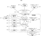
図1は、本発明を実施するため情報処理システムの1つの構成を示した概観図である。情報処理システムは運用管理システムと、運用管理サーバから構成される。運用管理システムは、ITシステムを構成する計算機、ネットワークスイッチ(NWスイッチ)、及びストレージ装置を管理対象として、運用管理サーバN0でこれらを監視・管理している。本発明の運用管理サーバN0は、管理対象のIT装置における状態変化、障害情報、通知情報などのイベント情報を受信するイベント受信部C0と、受信したイベント情報にもとづき、予め定義されたルールR0にもとづいて障害解析を行うルールエンジンC1と、管理対象のIT装置の構成情報を管理する構成管理C3と、これらの運用管理するために必要となる情報を画面に出力するための画面表示部C2が備わっている。 FIG. 1 is an overview diagram showing one configuration of an information processing system for carrying out the present invention. The information processing system includes an operation management system and an operation management server. The operation management system monitors and manages the computers, network switches (NW switches), and storage devices that make up the IT system as management targets and the operation management server N0. The operation management server N0 of the present invention has an event receiver C0 that receives event information such as state changes, failure information, and notification information in the IT device to be managed, and a rule R0 that is defined in advance based on the received event information. A rule engine C1 that performs failure analysis based on the configuration, a configuration management C3 that manages configuration information of IT devices to be managed, and a screen display unit C2 that outputs information necessary for managing these operations to the screen. It is equipped.
また、運用管理システムには、画面表示部の制御と出力データに基づいて、運用管理のための情報を画面に表示するための装置である画面出力装置M1があり、運用管理サーバN0と接続している。なお、画面出力装置M1としては第一に運用管理サーバに接続されたディスプレイ装置であることが考えられるが、運用管理システムの管理者に解析結果情報を表示することができれば他の装置で代替してもよい。画面出力装置M1のそのほかの例としては、画面出力装置として運用管理サーバN0が送信する電子メールを受信し、表示可能な携帯端末であったり、運用管理サーバN0が送信する解析結果情報を元に管理者に情報提供し、また管理者からの入力を受け付けて運用管理サーバN0に送信するディスプレイ付計算機がある。 Further, the operation management system includes a screen output device M1 that is a device for displaying information for operation management on the screen based on control of the screen display unit and output data, and is connected to the operation management server N0. ing. The screen output device M1 may be a display device connected to the operation management server in the first place. However, if the analysis result information can be displayed to the administrator of the operation management system, the screen output device M1 may be replaced with another device. May be. As another example of the screen output device M1, as a screen output device, an e-mail transmitted from the operation management server N0 can be received and displayed, or based on analysis result information transmitted from the operation management server N0. There is a computer with a display that provides information to an administrator and receives input from the administrator and transmits it to the operation management server N0.
ルールエンジンC1は、さらにイベントの相関解析のための解析ルール情報R0(以後、相関解析ルール情報と呼ぶことがある)を読みこみ、構成管理C3から構成情報T0を取得して、ルールをITシステムのIT装置に適用するための処理を行うルール適用部C11と、ルール適用部においてルールをIT装置に適用するための情報である適用情報を管理するルール適用先管理テーブルC130を管理し、ルールの解析処理を行うためのワーキングメモリであるルールメモリC13と、イベント受信部C0で受信したイベント情報を受け取り、イベントの相関解析を行う、イベント解析処理部C12から成る。なお、ルール適用先管理テーブルC130はルールメモリC13内に存在しなくても、運用管理サーバN0のメモリに格納されればよい。 The rule engine C1 further reads analysis rule information R0 (hereinafter also referred to as correlation analysis rule information) for event correlation analysis, acquires configuration information T0 from the configuration management C3, and stores the rules in the IT system. A rule application unit C11 that performs processing for application to the IT device, and a rule application destination management table C130 that manages application information that is information for applying the rule to the IT device in the rule application unit. A rule memory C13, which is a working memory for performing analysis processing, and an event analysis processing unit C12 that receives event information received by the event receiving unit C0 and performs correlation analysis of events. The rule application destination management table C130 may be stored in the memory of the operation management server N0 even if it does not exist in the rule memory C13.
なお、相関解析ルール情報は運用管理サーバN0の管理者によって作成・格納されてもよく、後述する本発明のプログラムに相関解析ルール情報を含めることでメモリに格納してもよく、または本発明のプログラムの初期化処理によって相関解析ルール情報をメモリに格納してもよい。 The correlation analysis rule information may be created and stored by the administrator of the operation management server N0, may be stored in the memory by including the correlation analysis rule information in the program of the present invention described later, or Correlation analysis rule information may be stored in the memory by program initialization processing.
なお、運用管理サーバN0を構成するハードウェアとしては、プロセッサ、メモリ(半導体メモリ及びHDDに代表される二次記憶装置を含む)、ネットワークポートがある。それぞれのハードウェアはバス等の内部ネットワークによって接続される。なお、イベント受信部C0、ルートエンジンC1、画面表示部C2、構成管理C3は運用管理サーバN0のメモリに格納され、プロセッサによって実行されるプログラムとして実現されることが第一に考えられるが、これら機能の一部または全てをハードウェアで実現してもよい。なお、以後の説明ではイベント受信部C0、ルートエンジンC1、画面表示部C2、構成管理C3を含むプログラムをイベント解析プログラムと呼ぶ。 Note that hardware constituting the operation management server N0 includes a processor, a memory (including a secondary storage device represented by a semiconductor memory and an HDD), and a network port. Each hardware is connected by an internal network such as a bus. The event receiving unit C0, the route engine C1, the screen display unit C2, and the configuration management C3 are stored in the memory of the operation management server N0 and can be realized as programs executed by the processor. Some or all of the functions may be realized by hardware. In the following description, a program including the event receiving unit C0, the route engine C1, the screen display unit C2, and the configuration management C3 is referred to as an event analysis program.
また、また、相関解析ルール情報R0、構成情報T0、ルール適用先管理テーブルC130は、運用管理サーバN0のメモリに格納されている。さらに、構成情報T0は後ほど説明する、IP−SANストレージ装置の接続情報(図8)、IP−SANストレージに関する情報(図9)、FC−SANストレージ装置の接続情報(図13)、FC−SANストレージに関する情報(図14)、ファイルサーバに関する識別情報と公開名(図15)の少なくとも一つが含まれる。また、後ほど説明する管理外IT装置管理テーブル(図11)についても構成情報に含まれるものとして説明するが、運用管理サーバN0のメモリに格納されていれば構成情報T0以外の情報として格納されていてもよい。 Further, the correlation analysis rule information R0, the configuration information T0, and the rule application destination management table C130 are stored in the memory of the operation management server N0. Further, the configuration information T0 will be described later, IP-SAN storage device connection information (FIG. 8), IP-SAN storage information (FIG. 9), FC-SAN storage device connection information (FIG. 13), FC-SAN. Information on storage (FIG. 14), identification information on file server, and public name (FIG. 15) are included. Also, the non-managed IT device management table (FIG. 11), which will be described later, will be described as being included in the configuration information. However, if it is stored in the memory of the operation management server N0, it is stored as information other than the configuration information T0. May be.
さらに、相関解析ルール情報R0、構成情報T0、ルール適用先管理テーブルC130、IP−SANストレージ装置の接続情報、IP−SANストレージに関する情報、FC−SANストレージ装置の接続情報、FC−SANストレージに関する情報、ファイルサーバに関する識別情報と公開名、管理外IT装置管理テーブルについてはテキストファイルやテーブル、キュー構造など特定のフォーマット、データ構造である必要はなく、後ほど説明する情報が含まれていればよい。以後の説明及び請求項にてより一般的な情報であることを明記するため、相関解析ルール情報R0、構成情報T0、ルール適用先管理テーブルC130、IP−SANストレージ装置の接続情報、FC−SANストレージ装置の接続情報、IP−SANストレージに関する情報、FC−SANストレージに関する情報、ファイルサーバに関する識別情報と公開名、管理外IT装置管理テーブルを、それぞれ相関解析ルール情報情報、構成情報、ルール適用先管理情報、IP−SANストレージ装置の接続情報、FC−SANストレージ装置の接続情報、IP−SANストレージに関する情報、FC−SANストレージに関する情報、ファイルサーバに関する識別及び公開名情報、管理外IT装置管理情報と呼ぶことがある。 Further, correlation analysis rule information R0, configuration information T0, rule application destination management table C130, IP-SAN storage device connection information, IP-SAN storage information, FC-SAN storage device connection information, FC-SAN storage information The identification information and public name related to the file server, and the unmanaged IT device management table do not need to have a specific format or data structure such as a text file, a table, or a queue structure, and may include information described later. In order to specify that it is more general information in the following description and claims, correlation analysis rule information R0, configuration information T0, rule application destination management table C130, IP-SAN storage device connection information, FC-SAN Storage device connection information, IP-SAN storage information, FC-SAN storage information, file server identification information and public name, unmanaged IT device management table, correlation analysis rule information, configuration information, rule application destination Management information, IP-SAN storage device connection information, FC-SAN storage device connection information, IP-SAN storage information, FC-SAN storage information, file server identification and public name information, unmanaged IT device management information Sometimes called.
なお、図示はしていないが、運用管理サーバは管理対象の様々なIT装置から受信するイベント情報をイベントエントリとしてメモリ内に定義したイベントデータベースに格納する。なお、イベントデータベースは一つ以上のイベントエントリが含まれていればどのようなデータ構造であっても良い。 Although not shown, the operation management server stores event information received from various IT devices to be managed as event entries in an event database defined in the memory. The event database may have any data structure as long as one or more event entries are included.
なお、イベント情報はイベント内容が含まれるが、イベント発生時間を含んでもよい。さらにイベントデータベースは過去のイベント情報を定められた条件に従って履歴として残しても良い。また、イベントデータベースに含め、メモリに格納する場合は、運用管理サーバのプログラム(特に構成管理C3)はイベント情報取得対象のIT装置の識別情報と、運用管理サーバによるイベント情報受信時間と関連付け、共に含めるようにしてもよい。なお、イベント内容は少なくともイベントの種別が含まれ、場合によっては当該イベントが発生IT装置内のハードウェア及びソフトウェアを特体する情報が含まれてもよい。 The event information includes event contents, but may include event occurrence time. Further, the event database may leave past event information as a history according to a predetermined condition. In addition, when stored in the memory in the event database, the operation management server program (particularly the configuration management C3) associates the identification information of the event information acquisition target IT device with the event information reception time by the operation management server. It may be included. Note that the event content includes at least the type of event, and in some cases, the event content may include information that identifies the hardware and software in the IT device in which the event occurred.
またイベントの種別としては例えば以下が考えれれるが、これ以外の種別が存在してもよい。
(A)当該IT装置のの稼動状態が予め定められた状態となったこと(例えばハードウェア障害や、ソフトウェア障害の発生がこれに含まれる)
(B)ヘルスチェック結果が予め定められた結果となったこと。(例えば一定時間ヘルスチェック応答が無かった場合がこれに含まれる)
(C)処理速度やIT装置を構成するコンポーネントであるプロセッサやメモリ、HDDなどの消費リソース量が予め定められた条件に適合したこと(例えばHDDの残り容量が10%を下回った場合がこれに含まれる)
(D)IT装置が予め定められた条件を満たすネットワークアクセスを受信したこと(例えば、IT装置が受信したリクエストが所定の回数を超えた場合や、リクエストされたDoS攻撃と識別されるネットワークパケットを所定回数受信した場合や、定められたIT装置以外のIT装置からリクエストを受信した場合がこれに含まれる)
なお、イベント解析プログラムのメモリへの格納は当該プログラムを記憶したDVD−ROMやCD−ROM等の媒体からのインストールやコピーによる方法や、運用管理サーバN0と通信可能なプログラム配布サーバからの当該プログラム(または当該プログラムをメモリ上で生成可能な情報)を受信する方法が考えられるが、これ以外の方法であってもよい。また、運用管理サーバN0へのプログラム格納を予め格納した後で運用管理サーバN0を流通させる形態であってもよい。
For example, the following event types are conceivable, but other event types may exist.
(A) The operating state of the IT device has become a predetermined state (for example, the occurrence of a hardware failure or a software failure is included in this).
(B) The health check result is a predetermined result. (For example, this includes cases where there was no health check response for a certain period of time)
(C) The processing speed and the amount of consumed resources such as the processor, memory, and HDD that are components constituting the IT apparatus meet predetermined conditions (for example, when the remaining capacity of the HDD falls below 10%) included)
(D) The IT device has received a network access that satisfies a predetermined condition (for example, when the number of requests received by the IT device exceeds a predetermined number of times, or when a network packet identified as a requested DoS attack is (This includes the case of receiving a predetermined number of times, and the case of receiving a request from an IT device other than the specified IT device)
The event analysis program is stored in the memory by a method of installation or copying from a medium such as a DVD-ROM or CD-ROM storing the program, or the program from a program distribution server that can communicate with the operation management server N0. A method of receiving (or information that can generate the program on the memory) is conceivable, but other methods may be used. Alternatively, the operation management server N0 may be distributed after storing the program storage in the operation management server N0 in advance.
以上説明した運用管理サーバN0によって情報処理システムの障害の根本原因を解析する。 The root cause of the failure of the information processing system is analyzed by the operation management server N0 described above.
なお、運用管理システムでは、予め管理する対象のIT装置を指定し、イベント情報を相関解析による解析対象として当該IT装置から必要な情報を受信する。このように運用管理システムにおいて、受信するIT装置を定めるのは、ネットワークに接続されたIT装置を全て管理することは、管理するために必要となる管理サーバのプロセッサ、メモリ、ハードディスクなどの記憶装置などの消費量が膨大となり、実用的な監視が困難であるため、管理する対象を絞ることでこれを回避するためである。また、管理ツールが商用のものである場合には、管理するIT装置の種類や台数などによりライセンス数に制限がある場合がほとんどである。このためITシステムにおいては、イベント情報解析のために、運用管理サーバN0がイベント情報を取得するまたは取得を許可されているIT装置(以後、監視されるIT装置、又は管理されるIT装置又は管理IT装置又は管理内IT装置又はイベント取得対象装置と表現することがある。なお同様の表現はIT装置の実態である計算機、スイッチ、ルータ、ストレージ装置に対しても適用する)と、運用管理サーバN0がイベント情報取得を取得しない又は取得を抑止されているIT装置(以後、監視されないIT装置、又は管理されないIT装置又は管理外のIT装置又は管理外IT装置又はイベント関連情報処理装置と表現することがある。なお同様の表現はIT装置の実態である計算機、スイッチ、ルータ、ストレージ装置に対しても適用する)が存在する。 In the operation management system, an IT device to be managed is designated in advance, and event information is received as an analysis target by correlation analysis, and necessary information is received from the IT device. In this way, in the operation management system, the IT devices to be received are determined because the management of all IT devices connected to the network is necessary for the management server processor, memory, hard disk and other storage devices This is to avoid this problem by narrowing down the objects to be managed. Further, when the management tool is a commercial tool, the number of licenses is often limited depending on the type and number of IT devices to be managed. For this reason, in the IT system, for event information analysis, the operation management server N0 acquires or is permitted to acquire event information (hereinafter, the IT device to be monitored, or the IT device to be managed or managed). It may be expressed as IT device, in-management IT device, or event acquisition target device (similar expressions apply to computers, switches, routers, storage devices that are the actual status of IT devices) and operation management server IT device in which N0 does not acquire or suppress acquisition of event information (hereinafter referred to as an unmonitored IT device, an unmanaged IT device, an unmanaged IT device, an unmanaged IT device, or an event-related information processing device) Note that the same expression applies to computers, switches, routers, and storage devices that are the reality of IT devices. Even if applied) are present.
運用管理サーバN0において監視・管理されないIT装置については、さらに、一度でも運用管理サーバN0において存在を発見、又は確認、又は管理されたことがあるIT装置と、一度も運用管理サーバN0において、その存在を発見、又は確認、又は管理されたことがないものに分類される。運用管理サーバN0によっては、一度でも管理したことがあるIT装置、又は発見、又は確認したことがあるIT装置については、監視・管理されているIT装置と同等とはいわないまでも、当該発見または確認によって取得した構成情報、例えばIT装置のIPアドレス、又はホスト名、又はFQDN(Fully Qualified Domain Name)などを内部に保持して管理するものもある。本発明では、対応する構成情報を運用管理サーバN0が持たない管理対象外のIT装置と、対応する構成情報の一部又は全てを運用管理サーバN0に格納済みの管理対象外のIT装置とを含めて、管理対象外のIT装置として定義する。 For IT devices that are not monitored and managed by the operation management server N0, the IT devices that have been found, confirmed, or managed at least once in the operation management server N0, Classified as having never been discovered, confirmed, or controlled. Depending on the operation management server N0, an IT device that has been managed even once, or an IT device that has been discovered or confirmed, may be discovered, even if it is not equivalent to an IT device that is monitored and managed Alternatively, there is a configuration in which configuration information acquired by confirmation, for example, an IP address of an IT apparatus, a host name, or a FQDN (Fully Qualified Domain Name) is stored and managed internally. In the present invention, an unmanaged IT device that does not have corresponding configuration information in the operation management server N0, and an unmanaged IT device in which part or all of the corresponding configuration information is already stored in the operation management server N0. It is defined as an IT device that is not managed.
運用管理システムの管理対象外であるケースとしては、DNSサーバのようにグローバルに提供されたサービスを管理対象内のIT装置が利用している場合や、ファイアーウォール、アクセス権の問題、ネットワーク構成、アクセス手段の不備などの事情により、運用管理システムが管理するための情報収集を十分に行えない場合などがある。 Cases that are not managed by the operation management system include cases where IT devices within the management target use services provided globally, such as DNS servers, firewalls, access rights problems, network configurations, There are cases where information collection for management by the operation management system cannot be sufficiently performed due to inadequate access means.
なお、本発明はネットワーク上に存在する複数のIT装置同士の相関解析を対象としている。しかし、本来相関のある複数装置である要因によるイベントが同時発生したとしても個々の装置のクロックにはずれが生じ、さらにイベント情報転送のタイミングにもずれが生じるため、運用管理サーバN0が解析対象とするイベント情報はプログラム開発者が予め定めたられた時間幅(期間)または管理者が定めた期間内に発生または受信したイベント情報を解析する。また、ある要因が発生したとしても当該要因に関係するイベントの発生はずれが生じることがあるため(例えば、WebサービスやDNSサービス等、サーバ計算機からキャッシング処理を介在させて所定のネットワークサービスを受ける場合)、特定の時間ではなくて期間を対象とした解析が必要となる。 The present invention is intended for correlation analysis between a plurality of IT devices existing on a network. However, even if events due to factors that are inherently correlated devices occur at the same time, the clocks of the individual devices are shifted, and the event information transfer timing is also shifted. The event information to be analyzed is event information generated or received within a time width (period) predetermined by the program developer or a period determined by the administrator. In addition, even if a factor occurs, the occurrence of an event related to the factor may occur (for example, when a predetermined network service is received from a server computer via a caching process such as a Web service or a DNS service) ), It is necessary to analyze the period rather than the specific time.
なお、イベントとして好適なものはある程度動的に発生する事項であることが好ましい。さらには、所定の要因が発生して要因となるIT装置でのイベントが発生(または運用管理サーバが受信)する時間と、当該要因を受けて別なIT装置でのイベントが発生(または運用管理サーバが受信)する時間の差が、前記期間内であるイベントの要因であることがより好適である。 In addition, it is preferable that what is suitable as an event is a matter which occurs dynamically to some extent. Furthermore, the time at which an event occurs in the IT device (or reception by the operation management server) due to the occurrence of a predetermined factor, and the event occurs in another IT device (or operation management in response to the factor) More preferably, the difference in time received by the server is a factor of an event within the period.
一方の構成情報として考えられる情報は、IT装置を構成するハードウェアの種類及び個数や、当該装置と通信するために必要な通信識別情報や名前といったものが好適であり、一部IT装置の管理者によって変更は可能であるが準静的な情報が好適である。 On the other hand, the information considered as the configuration information is preferably the type and number of hardware constituting the IT device, communication identification information and name necessary for communicating with the device, and some IT device management Although it can be changed by a person, quasi-static information is preferable.
図2は、上記の構成にもとづく本発明における実施形態の1つの大まかな処理の流れを示したものである。 FIG. 2 shows a rough processing flow of one embodiment of the present invention based on the above configuration.
S1においてルールエンジンC1は、予め相関解析ルール情報R0を読み込み、構成管理C3から管理対象の構成情報T0を取得して、ルール群R0の適用先のIT装置の識別情報をT0から検索して、ルール適用先管理テーブルC130に格納しておく。S1の処理は、この後に行うイベントによる障害解析処理のための準備であり、解析処理の前までに行えばよい。実施形態の1つである第一実施形態では、解析処理を運用開始前に行い、予めルール適用先管理テーブルC130をルールメモリC13内に保持しているものとする。 In S1, the rule engine C1 reads the correlation analysis rule information R0 in advance, acquires the configuration information T0 to be managed from the configuration management C3, searches the identification information of the IT device to which the rule group R0 is applied from T0, It is stored in the rule application destination management table C130. The process of S1 is a preparation for a failure analysis process by an event to be performed thereafter, and may be performed before the analysis process. In the first embodiment, which is one of the embodiments, the analysis process is performed before the operation is started, and the rule application destination management table C130 is held in the rule memory C13 in advance.
S2においては、イベント受信部C0にて、運用管理システム内の管理対象のIT装置から上げられるイベントの受信待ちうけを行う。 In S2, the event reception unit C0 waits for reception of an event raised from the IT device to be managed in the operation management system.
S3では、運用管理システムの運用操作に関するものであり、停止処理が指示されたかどうかを確認するためのステップであり、運用の停止を行うためのものである。 S3 relates to the operation operation of the operation management system, and is a step for confirming whether stop processing is instructed, and for stopping the operation.
S4においては、イベント受信部C0でイベントを受信したかどうかの判断を行う。受信した場合には、S5においてイベント受信部C0より受信したイベントをイベント解析処理部C12に入力して、ルール適用先管理テーブルC130にもとづいて該当するルールを求めて、該ルールに従い障害原因を特定する。 In S4, it is determined whether the event reception unit C0 has received an event. If received, the event received from the event receiving unit C0 in S5 is input to the event analysis processing unit C12, the corresponding rule is obtained based on the rule application destination management table C130, and the cause of the failure is specified according to the rule. To do.
S5においては、特定した障害原因を画面表示部C14に出力する。画面表示部C14は、受け取った解析結果出力データを元に解析情報を送信することで、画面出力装置M1に運用管理に必要な画面を出力・表示する。 In S5, the specified cause of failure is output to the screen display unit C14. The screen display unit C14 outputs and displays a screen necessary for operation management on the screen output device M1 by transmitting analysis information based on the received analysis result output data.
なお、S2及びS4の処理の代替として受信したイベント情報を一旦イベントデータベースに格納してもよい。 The received event information may be temporarily stored in the event database as an alternative to the processing of S2 and S4.
この大まかな処理の流れにおいて、ルール適用部の処理に手を加えることで、構成やその後の処理の流れを大幅に変えることなく、管理対象でないIT装置の障害の原因解析を行えることが本発明の効果の1つである。 In this rough processing flow, by modifying the processing of the rule application unit, it is possible to analyze the cause of a failure of an IT device that is not a management target without significantly changing the configuration and the subsequent processing flow. This is one of the effects.
図3は、本発明の実施形態で想定するITシステムの構成の1つを示した概観図である。図3のITシステムは、管理サーバN0が運用管理する計算機N10、計算機N11、計算機N12と、ネットワークスイッチであるIPスイッチN21とFCスイッチN31、ストレージ装置N40とストレージ装置 N41で構成される運用管理対象である運用管理システムと、管理サーバN0が管理しない管理対象外のIT装置としてストレージ装置U2と計算機U5と、ルータN20を介してネットワークG0に接続されるストレージ装置U1と、計算機U3と計算機U4と、から構成される。なお、個々で記した計算機、スイッチ、ルータ、ストレージ装置等のIT装置の個数は一例であり、少なくともネットワークサービスを提供するサーバの役目を持ったIT装置と、当該ネットワークサービスの提供を受けるクライアントの役目を持ったIT装置が運用管理システムに含まれていればよい。 FIG. 3 is an overview diagram showing one configuration of the IT system assumed in the embodiment of the present invention. The IT system of FIG. 3 is an operation management target composed of a computer N10, a computer N11, and a computer N12 that are managed by a management server N0, an IP switch N21 and an FC switch N31 that are network switches, a storage device N40, and a storage device N41. An operation management system, a storage device U2 and a computer U5 as IT devices that are not managed by the management server N0, a storage device U1 connected to the network G0 via the router N20, a computer U3, and a computer U4 Is composed of. Note that the number of IT devices such as computers, switches, routers, storage devices, etc. described above is merely an example, and at least the IT devices that act as servers that provide network services and the clients that receive the network services are provided. It is only necessary that the IT apparatus having the role is included in the operation management system.
管理対象外のIT装置のストレージ装置U1はIP−SANのインタフェースを備えるストレージ装置であり、管理対象の計算機N10に対して論理ボリュームを提供している。また、管理対象外のIT装置のストレージ装置U2はFC−SANのインタフェースを備えるストレージ装置であり、管理対象のFCスイッチN31を介して管理対象の計算機N13に対して論理ボリュームを提供している。管理対象外のIT装置の計算機U3又は計算機U5はファイルサーバであり、それぞれ管理対象の計算機N10、N11の両方にファイルシステムを公開しているが、計算機U3は運用管理システムとは違うネットワークセグメントに属しており、計算機U3に関する詳細な情報はネットワーク上から取得できないようになっている。 The storage apparatus U1 of the IT apparatus that is not a management target is a storage apparatus that has an IP-SAN interface and provides a logical volume to the management target computer N10. The storage apparatus U2 of the IT apparatus that is not managed is a storage apparatus that has an FC-SAN interface, and provides a logical volume to the managed computer N13 via the managed FC switch N31. The computer U3 or the computer U5 of the IT apparatus that is not managed is a file server, and the file system is open to both the managed computers N10 and N11. However, the computer U3 is in a network segment different from the operation management system. Detailed information about the computer U3 cannot be acquired from the network.
一方で、計算機U5のファイルサーバは、運用管理システムと同一のネットワークセグメントに属しており、運用管理システムにより自動で存在を発見することができる計算機で、運用時に発見されたが、管理対象とはされなかったIT装置である。また、管理対象外のIT装置の計算機U4はDNSサーバであり、図3のITシステムの全てのIT装置に対して名前解決機能を適用している。 On the other hand, the file server of the computer U5 belongs to the same network segment as the operation management system, and is a computer that can be automatically detected by the operation management system. IT equipment that was not done. Further, the computer U4 of the IT device that is not managed is a DNS server, and the name resolution function is applied to all IT devices of the IT system of FIG.
ここでは理解のために第一実施形態について述べる前に、管理対象のIT装置に対し、イベント相関技術のルールをどのように適用するかについて説明する。 Here, for the sake of understanding, before describing the first embodiment, how to apply the rules of the event correlation technique to the IT device to be managed will be described.
図4は、図1で示したITシステムに対して、ストレージ装置のコントローラの障害が根本原因であることを示唆するルールの例である。こうした障害解析の根本原因を特定するルールは、イベント相関に基づき、発生すると予測されるイベントの組み合わせと、根本原因となる障害のペアをif−then形式で示すことが多い。if−then形式のルール表現においては、“もしif に記述された条件が成立するならば、then部分が真である”のような意味のルールを表記する。 FIG. 4 is an example of a rule that suggests that the failure of the controller of the storage apparatus is the root cause for the IT system shown in FIG. Such a rule for identifying the root cause of failure analysis often indicates a combination of events predicted to occur and a pair of failure causing the root cause in an if-then format based on event correlation. In the rule expression of the if-then format, a rule having a meaning such as “if the condition described in if is satisfied, the then part is true” is written.
実施例では、エキスパートシステムなどの一般的なルールと同様にif−thenの形式でルールが記述されているものとし、ルールの適用対象となるIT装置に関する情報がifの条件部分に予め定義されているものとする。なお、ルールの記述形式自体はif−then形式でなくても良く、ルールを適用する対象となるIT装置が特定できる何かしらの接続・関係情報としてトポロジが予め定義されていればよい。 In the embodiment, it is assumed that the rule is described in the if-then format in the same manner as a general rule such as an expert system, and information regarding the IT device to which the rule is applied is defined in the condition part of the if in advance. It shall be. Note that the rule description format itself does not have to be an if-then format, and the topology only needs to be defined in advance as some connection / relationship information that can identify the IT device to which the rule is applied.
なお、それぞれのルールを実際に格納する情報はルールエントリである。相関解析ルール情報は一つ以上のルールエントリを含む。なお、より抽象化すると当該ルールエントリは以下の情報が含まれると言っても良い。
(A)当該ルールが適合するイベントの種別を含んだ条件を示す条件エントリ。上記の通り、この条件エントリにはトポロジを条件として含めてもよい。
(B)当該条件が適合した場合に原因となるイベントと、当該イベントが関係するIT装置又はIT装置のハードウェア・ソフトウェアの箇所を表す原因エントリ。
Information that actually stores each rule is a rule entry. The correlation analysis rule information includes one or more rule entries. Note that, when abstracted, the rule entry may include the following information.
(A) A condition entry indicating a condition including the type of event to which the rule conforms. As described above, the condition entry may include the topology as a condition.
(B) A cause entry indicating an event that is a cause when the condition is met and a location of the IT apparatus or the hardware / software of the IT apparatus related to the event.
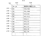
第1実施例として、iSCSIを利用したIP−SANのストレージ装置のコントローラ障害を根本原因とするルールR1と、Fibre Channelを利用したFC−SANのストレージ装置のコントローラ障害を根本原因とするルールR2と、ファイルサーバの障害を根本原因とするルールR3と、DNSサーバへのネットワーク不到達を根本原因とするルールR4が図4に示すように予め定義されているものとする。また、図6には、ルールに対して、該ルールを適用するIT装置を保持する情報である、ルール適用先管理テーブルを示した。ルール適用先管理テーブルは、ルールを指し示す識別情報のカラムC101とそのルールを適用させる対象のIT装置の識別情報を格納する適用先IT装置のリストのカラムC102から成る情報であり、データベース上のテーブルである必要はない。なお、本テーブル状のデータ構造は、テーブルを正規化することにより、複数のテーブル状のデータ構造に分割して管理されていてもよい。 As a first embodiment, a rule R1 based on a controller failure in an IP-SAN storage device using iSCSI, a rule R2 based on a controller failure in an FC-SAN storage device using Fiber Channel, Assume that a rule R3 whose root cause is a failure of a file server and a rule R4 whose root cause is a network non-reachability to a DNS server are defined in advance as shown in FIG. FIG. 6 shows a rule application destination management table, which is information for holding an IT device to which the rule is applied, for the rule. The rule application destination management table is information including a column C101 of identification information indicating a rule and a column C102 of a list of IT devices to which the rule is applied to store the identification information of an IT device to which the rule is applied. Need not be. The table-like data structure may be managed by dividing the table into a plurality of table-like data structures by normalizing the table.
図3で示したルールR1乃至R4 に対して、それぞれのルールを適用させるトポロジのパターンを図5に示した。図5の(1)は、ルールR1のIF部が示唆する接続・関係情報のトポロジを示しており、計算機を示すComputerが、iScsiInitiatorを持ち、IPスイッチを示すIpSwitchを介して、ストレージ装置を示すStorageのiScsiTargetと接続されていることを示す。iScsiTargetは、iScsiInitiatorの接続先を識別するためのiSCSI名であり、計算機が持つ接続先のiScsiTargetと、ストレージ装置が持つiScsiのポートのiSCSI名が一致する計算機とストレージ装置の組み合わせに対してルールR1が適用される。図3で示されるITシステムにおいては、ルールR1の適用先のIT装置は図6のL101とL102の行のようになる。 FIG. 5 shows a topology pattern in which each rule is applied to the rules R1 to R4 shown in FIG. (1) in FIG. 5 shows the topology of the connection / relation information suggested by the IF part of the rule R1, and the computer indicating the computer has an iScsiInitiator and indicates the storage device via the IpSwitch indicating the IP switch. Indicates that it is connected to the Storage iScsiTarget. The iScsiTarget is an iSCSI name for identifying the connection destination of the iScsiInitiator, and the rule R1 for the combination of the computer and the storage device in which the iSCSI target of the connection destination of the computer and the iSCSI name of the iScsi port of the storage device match. Applies. In the IT system shown in FIG. 3, the IT apparatus to which rule R1 is applied is as shown in the rows L101 and L102 in FIG.
また、図5の(2)についても同様に、ルールR2のIF部が示唆するように、計算機がFcHbaを備え、FcHbaがFcSwitchを介して、ストレージ装置のFcPortに繋がっていることを示す。このとき、FcHbaが持つ接続先ポートWWN(WWN: World Wide Name)と、ストレージ装置のFibre ChannelのポートであるFcPortのWWNであるFcPortWWNは一致しているものを接続関係があるものとしてルールR2の適用対象とする。図3のITシステムにおいて、これらの計算機とストレージ装置の組み合わせとしてルールR2の適用先のIT装置は図6のL103の行になる。 Similarly, (2) in FIG. 5 indicates that the computer includes FcHba, and FcHba is connected to FcPort of the storage apparatus via FcSwitch, as suggested by the IF part of rule R2. At this time, the connection destination port WWN (WWN: World Wide Name) possessed by FcHba and the FcPortWWN which is the WWN of the FcPort which is the Fiber Channel port of the storage apparatus are regarded as having a connection relationship, and the rule R2 Applicable. In the IT system of FIG. 3, the IT device to which the rule R2 is applied as a combination of these computers and storage devices is the row of L103 in FIG.
図5の(3)については、ルールR3のIF部がファイルサーバ−クライアントのトポロジを示している。ファイルサーバのファイルシステムをマウントしていることを示す情報ImportedFileShareを持つコンピュータT31と、外部にファイルシステムを公開していることを示す情報ExportedFileShareを持つコンピュータT33は、IPスイッチT32を介してそれぞれクライアント−ファイルサーバの関係である。このとき、ImportedFileShare T311にはマウント元のファイルサーバに関する情報として、ファイルサーバの識別情報(IPアドレスやFQDN(Fully Qualified Domain Name)など)と、公開しているファイルシステムの公開名を持ち、ExportedFileShare T331には、公開しているファイルシステムの場所と公開名(共有名とも呼ばれる)を持つ。 As for (3) in FIG. 5, the IF part of the rule R3 indicates the file server-client topology. The computer T31 having the information ImportedFileShare indicating that the file system of the file server is mounted and the computer T33 having the information ExportFileShare indicating that the file system is disclosed to the outside are respectively connected to the client − via the IP switch T32. This is a file server relationship. At this time, ImportedFileShare T311 has file server identification information (IP address, FQDN (Fullly Qualified Domain Name), etc.) and the public name of the public file system as the information related to the mount source file server, and ExportFileShare T331. Has a public file system location and a public name (also called a shared name).
ImportedFileShareが指しているファイルサーバの識別情報で示されるコンピュータで、なおかつそのコンピュータがExportedFileShareの情報を持ち、ExportedFileShareの公開名がコンピュータT31のImportedFileShareが指している公開名と一致するコンピュータのペアをファイルクライアント−ファイルサーバのトポロジとしてルールR3を適用する。したがって、図3のITシステムにおいては、これを満たす組み合わせとしてルールR3の適用先のIT装置は図6のL104の行になる。 A file client is a computer pair indicated by the identification information of the file server pointed to by the ImportedFileShare, the computer has the information of the ExportFileShare, and the public name of the ExportFileShare matches the public name of the ImportedFileShare of the computer T31. Apply rule R3 as the file server topology. Therefore, in the IT system of FIG. 3, the IT apparatus to which the rule R3 is applied as a combination satisfying this is the line L104 in FIG.
図5の(4)については、ルールR4が示唆するDNSサーバとクライアントのトポロジであり、名前解決サービスを提供しているDNSサーバであるコンピュータT42と、DNSサーバによりIPアドレスとFQDNの名前を解決しているクライアントのコンピュータT41がペアとなって、図6に示す適用先管理テーブルに格納される。 For (4) in FIG. 5, the topology of the DNS server and client suggested by rule R4 is to resolve the IP address and FQDN name by the computer T42, which is a DNS server providing a name resolution service, and the DNS server. The client computer T41 is paired and stored in the application management table shown in FIG.
こうしたルールに記述された接続や関係に関するトポロジ情報に対する構成は、予めシステムで定義されているものとし、ルールの記述によって一意に定められる。 The configuration for topology information related to connections and relationships described in such rules is defined in advance by the system, and is uniquely determined by the description of the rules.
ルールに対する適用先のIT装置に関しては図6の適用先管理テーブルを持つことにより、イベント発生時にこのテーブルを参照することで、イベントがどのルールに関連するものなのかを判断し、適用すべきルールを選択することができる。以上が、管理対象のIT装置に対するルールの適用方法である。 Regarding the IT device to which the rule is applied, by having the application management table shown in FIG. 6, it is possible to determine which rule the event relates to by referring to this table when an event occurs and to apply the rule. Can be selected. The above is the rule application method for the IT device to be managed.
図7及び図21及び図21は、図2のルール適用部C11におけるステップS1について、本発明の実施形態の1つを詳細化したものである。この処理フローに従い、図3のITシステムと、図4のルールR1乃至R4を想定して第一実施形態を説明する。なお、図7及び図21及び図21の処理は、全てルール適用部において行われるものである。また、予め運用管理システムは、一度発見したことがあるIT装置について記憶しており、発見済みのIT装置であると判断できることを前提とする。あるいは、運用管理システムが、ITシステム内のIT装置を自動で発見する機能を持たない場合、又は自動で発見する機能を持っていても、発見したIT装置について記憶する機能がない場合には、発見済みのIT装置は存在しないものとして図7及び図21の処理を行う。 7, 21, and 21 detail one embodiment of the present invention for step S <b> 1 in the rule application unit C <b> 11 of FIG. 2. According to this processing flow, the first embodiment will be described assuming the IT system of FIG. 3 and the rules R1 to R4 of FIG. 7, 21, and 21 are all performed by the rule application unit. Further, it is assumed that the operation management system stores in advance IT devices that have been discovered once and can determine that the IT device has been discovered. Alternatively, if the operation management system does not have a function to automatically find an IT device in the IT system, or has a function to automatically find an IT device, but does not have a function to store the found IT device, The processing shown in FIGS. 7 and 21 is performed assuming that no discovered IT device exists.
(一般的なフローの説明及びルールR1を適用した場合について)
S101において、相関解析ルール情報情報R0に読み込むルール、すなわち読み込み済みでないルールが存在するかを判断する。判断の結果、読み込むルールが存在する(YESの)場合には、S102に移る。そうでなければ(NOの場合)終了する。読み込むルールはR1乃至R4と存在するので、ここではYESとなりS102に移る。
(Regarding general flow explanation and rule R1 applied)
In S101, it is determined whether there is a rule to be read into the correlation analysis rule information information R0, that is, a rule that has not been read. As a result of the determination, if there is a rule to be read (YES), the process proceeds to S102. If not (NO), the process ends. Since the rules to be read exist as R1 to R4, YES is determined here, and the process proceeds to S102.
S102においては、ルールを1つ読み込み、読み込み済みとわかるように、例えばしるしをつけたり、読み込み済みのルールとして記憶したりする。実施形態では、ルールのR1を読み込み、ルールR1を読み込み済みルールとして記憶してS103に移る。 In S102, one rule is read and, for example, a mark is added or stored as a read rule so that it can be recognized that the rule has been read. In the embodiment, the rule R1 is read, the rule R1 is stored as a read rule, and the process proceeds to S103.
S103においては、ルールに記述されたトポロジ情報に対応するIT装置の検索条件を求めてS4に移る。実施形態では、ルールR1のトポロジ情報として、iScsiInitiatorを持つ計算機と、iScsiTargetで識別されるiSCSIのポートを持つストレージ装置、およびこれらに接続されたIPスイッチがルールR1を適用するIT装置の検索条件となる。検索条件は、予めルールの記述に対して定義されているものとする。 In S103, the search condition of the IT apparatus corresponding to the topology information described in the rule is obtained, and the process proceeds to S4. In the embodiment, as topology information of the rule R1, as a search condition of the IT device to which the computer having the iScisiInitiator, the storage device having the iSCSI port identified by the iScsiTarget, and the IP switch connected thereto apply the rule R1 Become. The search condition is defined in advance for the rule description.
S104においては、トポロジ情報のうち、クライアント側のIT装置を管理対象のIT装置の構成情報から検索する。なお、構成情報の検索は、構成情報を管理しているものがデータベースであればデータベースに対して行い、ファイルであればファイルに対して行い、検索対象とする記憶メディアやデバイスなどは問わない。実施形態では、ルールR1のトポロジにおいてクライアントを示す、iScsiInitiatorを持つ計算機を構成情報から検索する。本実施例では、計算機N10又は計算機N11がiScsiInitiatorを持つものとすると、計算機N10と計算機N11の識別情報が検索により見つかる。 In S104, the client side IT device is searched from the configuration information of the management target IT device in the topology information. The configuration information search is performed on the database if the configuration information is managed, and the search is performed on the file if the file is a file, regardless of the storage medium or device to be searched. In the embodiment, a computer having an iScsiInitiator indicating a client in the topology of the rule R1 is searched from the configuration information. In this embodiment, if the computer N10 or the computer N11 has an iScsiInitiator, the identification information of the computer N10 and the computer N11 is found by the search.
S105においては、S106以降の処理を複数の計算機の場合について実行するため、検索で見つかったIT装置で未選択なIT装置があるかを判断する。本実施例では、計算機N10と計算機N11が未選択なIT装置であるためS106に進む。 In S105, since the processes after S106 are executed for a plurality of computers, it is determined whether there is an unselected IT apparatus among the IT apparatuses found by the search. In this embodiment, since the computer N10 and the computer N11 are unselected IT devices, the process proceeds to S106.
S106においては、未選択なIT装置から1つを選択し、選択済みとする。本実施例では計算機N10を選択し、計算機N10を選択済みとしてS107に進む。 In S106, one of the unselected IT devices is selected and is selected. In this embodiment, the computer N10 is selected, and the computer N10 is selected, and the process proceeds to S107.
S107においては、S106に於いて選択したIT装置とトポロジ上で対向となるサーバ側のIT装置の情報を取得する。ここでサーバ側のIT装置の情報としては、サーバ側のIT装置を識別する情報(IPアドレス、又はホスト名、FQDNなど)や、提供するサービスに関する情報(ファイルサーバにおける公開ファイルシステムの公開名(共有名とも呼ばれる)や、ストレージ装置のディスクボリュームを識別するLUN番号、あるいは接続先のiSCSI名、またはFC PortのWWN)がある。本実施例では、計算機N10に対向するサーバ側のストレージ装置の情報として、図8に示す接続先のiSCSI名であるConnectedIscsiTargetを取得する。 In S107, information on the IT apparatus on the server side that is opposite in topology to the IT apparatus selected in S106 is acquired. Here, the server-side IT device information includes information for identifying the server-side IT device (IP address, host name, FQDN, etc.), information on the service to be provided (public name of the public file system on the file server ( Or a LUN number for identifying a disk volume of a storage device, an iSCSI name of a connection destination, or an FC Port WWN). In the present embodiment, ConnectedIscsiTarget, which is the iSCSI name of the connection destination shown in FIG. 8, is acquired as information on the server-side storage apparatus facing the computer N10.
S108においては、S107で取得したサーバ側のIT装置に関する情報のうち、その情報に対応するIT装置を検索していないものが存在するかを判断し、存在する(YES)場合にはS109に、存在しない(NO)場合にはS105に移る。本実施例では、図8に示すように少なくとも3つの未検索の情報が存在する(YES)ため、S109に移る。 In S108, it is determined whether there is information on the server-side IT device acquired in S107 that has not been searched for an IT device corresponding to the information. If YES (YES), the process proceeds to S109. If it does not exist (NO), the process proceeds to S105. In the present embodiment, as shown in FIG. 8, since there are at least three unsearched information (YES), the process proceeds to S109.
なお、ここで図8に含まれる情報を説明すると、当該情報にはIT装置(より具体的には計算機)を示す識別情報と、当該IT装置が接続先とするストレージ装置のiSCSIにおける識別情報を有する。 Here, the information included in FIG. 8 will be described. The information includes identification information indicating an IT apparatus (more specifically, a computer) and iSCSI identification information of a storage apparatus to which the IT apparatus is connected. Have.
S109においては、S107で取得したサーバ側のIT装置の情報のうち、未検索のものを1つ選択し、この情報を元にサーバ側のIT装置を管理対象の構成情報から検索する。本実施例では、計算機N10より取得した図8に示されるConnectedIscsiTargetのL201行で示されるiSCSI名をiScsiTargetに持つストレージ装置を管理対象の構成情報から検索する。 In S109, one piece of unsearched information is selected from the server-side IT device information acquired in S107, and the server-side IT device is searched from the configuration information to be managed based on this information. In the present embodiment, the storage device having the iSCSI name shown in the L201 line of the ConnectedIscsiTarget shown in FIG. 8 acquired from the computer N10 in the iScsiTarget is searched from the configuration information to be managed.
S110において、S109の検索の結果、管理対象のIT装置に該当するものが存在しない(NO)場合には、S111に移る。一方で、管理対象のIT装置に該当するものが存在する(YES)場合には、通常のルール適用処理と同様となり、S121に移る。本実施例では、管理対象のストレージ装置のiScsiTargetに関する構成情報は図9に示したものとする。このとき、図8のL201行のConnectedIscsiTargetと一致するiScsiTargetを持つストレージ装置は図9に示したように管理対象には存在しないため、S111に移る。 In S110, if the result of the search in S109 is that there is no management target IT device (NO), the process proceeds to S111. On the other hand, if there is a device corresponding to the IT device to be managed (YES), the processing is the same as the normal rule application processing, and the process proceeds to S121. In this embodiment, it is assumed that the configuration information related to the iStorage Target of the storage device to be managed is as shown in FIG. At this time, since the storage apparatus having the iScsiTarget that matches the ConnectedIscsiTarget of the L201 line in FIG. 8 does not exist in the management target as shown in FIG. 9, the process proceeds to S111.
なお、ここで図9に含まれる情報を説明すると、当該情報にはストレージ装置を示す識別情報と、当該ストレージ装置が有するiSCSIにおける識別情報を有する。 Here, the information included in FIG. 9 will be described. The information includes identification information indicating a storage apparatus and identification information in iSCSI included in the storage apparatus.
なお、発見済みの一つ以上のIT装置毎に当該装置がイベント取得対象であるかどうか(すなわち当該装置が監視される装置であるかどうか、言い方を代えると当該装置に対するイベント取得を許可しているか抑止しているか)を示すイベント取得可否情報が構成情報T0に含まれており、当該データを参照することでS110の判断を行う。 It should be noted that for each one or more discovered IT devices, whether or not the device is an event acquisition target (that is, whether or not the device is a monitored device, in other words, permitting event acquisition to the device) Event acquisition permission / inhibition information indicating whether or not) is included in the configuration information T0, and the determination in S110 is performed by referring to the data.
S111においては、運用管理システムにおいて既に発見したことがあるIT装置であるかどうかを判断する。すなわち、運用管理システムにおいて、一度でも存在を発見、又は確認、又は管理されたことがあるIT装置であって、部分的に運用管理システムが静的構成情報を持つようなIT装置であるかどうかをここでは判断する。本実施例では、図8のL201行のConnectedIscsiTargetと一致するiScsiTargetを持つストレージ装置に関する構成情報は一切なく、発見済みリソースでない(NO)であるものとしてS112に進む。 In S111, it is determined whether or not the IT apparatus has already been discovered in the operation management system. That is, whether or not the operation management system is an IT device whose presence has been discovered, confirmed, or managed even once, and the operation management system partially has static configuration information. Judge here. In the present embodiment, there is no configuration information related to the storage apparatus having the iScsiTarget that matches the ConnectedIscsiTarget in the L201 line in FIG. 8, and the process proceeds to S112 assuming that the resource is not a discovered resource (NO).
なお、S111の判断は構成情報に当該装置に関する情報(例えばイベント取得可否情報)が存在するかどうかで判別する方法がある。 Note that the determination in S111 includes a method of determining whether there is information (for example, event acquisition availability information) related to the device in the configuration information.
S112において、図8のL201行のConnectedIscsiTargetと一致するiScsiTargetを持つストレージ装置を、管理外のIT装置から発見を試みる。S112の管理外IT装置の有無の検索方法の一例としては、構成情報より取得、又はユーザにより入力された対象となるリソースに対応するIPアドレスやFQDNなどの通信識別子、又は構成情報から取得、又はユーザにより入力された対象となるリソースを含むネットワークセグメントに対応するIPアドレスであるネットワークアドレス内のIPアドレス、又はFQDNなどの通信識別子に対して、対象となるリソースに関するサービス提供を求めるリクエストを送信し、その応答の有無を待って対象とするリソースの存在を確認する方法がある。本実施例では、図3に示すITシステムから発見を試みる。 In S112, an attempt is made to discover a storage apparatus having an iScsiTarget that matches the ConnectedIscsiTarget in the L201 line in FIG. 8 from an unmanaged IT apparatus. As an example of a search method for the presence / absence of an unmanaged IT device in S112, it is acquired from configuration information, or acquired from a communication identifier such as an IP address or FQDN corresponding to a target resource input by a user, or configuration information, or A request for providing a service related to the target resource is transmitted to the IP address in the network address corresponding to the network segment including the target resource input by the user or a communication identifier such as FQDN. There is a method for confirming the existence of the target resource after waiting for the response. In the present embodiment, discovery is attempted from the IT system shown in FIG.
S113においては、S112で試みた発見が成功したかどうかを判断する。成功した(YES)場合にはS14に移る。さもなければ(NO)S116に移る。本実施例では、図3に示すストレージ装置U3が該当するストレージ装置として発見されたものとしてS114に移る。 In S113, it is determined whether the discovery attempted in S112 is successful. If successful (YES), the process proceeds to S14. Otherwise (NO), the process proceeds to S116. In this embodiment, the process moves to S114 on the assumption that the storage apparatus U3 shown in FIG. 3 has been found as the corresponding storage apparatus.
S114においては、S113に於いて発見したIT装置を、運用管理システムの管理対象とすることができるかどうかを判断する。管理対象とすることができるかどうかの判断は、その運用管理システムが監視・管理するために必要となる情報が、対象のIT装置から取得できるかどうかで判断する。監視・管理するために必要となる情報については、運用管理システムごとに様々であるが、共通的なものとしては、そのIT装置を識別する情報、例えばIPアドレス、又はWWN(World Wide Name)、又は何かしらのユニークな識別情報(番号)、装置名(ホスト名)、FQDNなど、少なくとも1つ以上の情報である。 In S114, it is determined whether the IT device discovered in S113 can be set as a management target of the operation management system. Judgment as to whether or not it can be managed is based on whether or not the information necessary for the operation management system to monitor and manage can be acquired from the target IT device. Information necessary for monitoring and management varies depending on the operation management system. Common information includes information for identifying the IT device, for example, an IP address, or WWN (World Wide Name), Alternatively, it is at least one piece of information such as some unique identification information (number), device name (host name), FQDN, or the like.
また、そのIT装置を構成するハードウェアの種類または個数に関する一つ以上の情報も、ある程度は取得できるほうが好ましい。本発明では、運用管理サーバN0が所定の判断基準を持ち、その判断基準によってこの判断を行うものとする。本実施例では、ストレージ装置U3に関する情報として、このストレージ装置がiSCSIのポートを備え、そのiSCSIポートのiSCSI名としてiScsiTargetの情報が取得できるものとし、管理対象にすることができると判定されたものとしてS115に進む。なお、続く処理にて当該装置を管理対象とする場合があるため、本ステップにて当該IT装置からイベント情報が受信可能であることを確認処理に加え、確認できた場合のみS115に進むようにしてもよい。 Further, it is preferable that one or more pieces of information regarding the type or number of hardware constituting the IT apparatus can be acquired to some extent. In the present invention, it is assumed that the operation management server N0 has a predetermined criterion and makes this determination based on the criterion. In this embodiment, as the information regarding the storage apparatus U3, it is determined that this storage apparatus has an iSCSI port, and the iSCSI name of the iSCSI port can be acquired as the iSCSI target information and can be managed. The process proceeds to S115. Since the device may be a management target in subsequent processing, it is determined in this step that the event information can be received from the IT device in addition to the confirmation processing. Good.
S115においては、S113において発見されたIT装置を管理対象とするかどうかをユーザに提示する。本実施例では、ストレージ装置U3が計算機N1のストレージサーバとして発見されたことと、ストレージ装置U3を管理対象に入れるかどうかを提示する。提示画面は、図10である。 In S115, the user is shown whether or not the IT device discovered in S113 is to be managed. In this embodiment, the storage device U3 is discovered as a storage server of the computer N1, and whether or not the storage device U3 is to be managed is presented. The presentation screen is shown in FIG.
S116においては、運用管理サーバN0(特にルールエンジン)は管理画面出力装置からの入力を受信する。 In S116, the operation management server N0 (particularly the rule engine) receives an input from the management screen output device.
S117において、ユーザが発見したIT装置を管理対象したかどうかを判断し、管理対象とした(YES)場合にはS118に進み、そうでなければ(NO)S119に進む。本実施例においては、ユーザはストレージ装置U3を管理対象としなかったものとしS119に進む。 In S117, it is determined whether or not the IT device discovered by the user is a management target. If the IT device is a management target (YES), the process proceeds to S118. Otherwise (NO), the process proceeds to S119. In this embodiment, it is assumed that the user has not managed the storage apparatus U3, and the process proceeds to S119.
S118においては、ユーザが管理対象に含める判断をしたIT装置に対して情報を取得し、管理対象のIT装置として構成管理に情報を格納する。本実施例では、この時点ではこちらの分岐には来ていない。 In S118, information is acquired for the IT device that the user has decided to include in the management target, and the information is stored in the configuration management as the IT device to be managed. In this embodiment, this branch has not been reached at this point.
S119においては、クライアントと対向となるサーバを、管理外IT装置として管理外IT装置管理テーブルに取得可能な情報について格納して管理し、S120に進む。本実施例では、ストレージ装置U3について、装置を識別する情報としてFQDNと、ストレージ装置のIPポートのiSCSI名であるiScsiTargetが取得可能な情報であるものとし、これを図11の管理外IT装置管理テーブルTL3に格納する。 In S119, the server opposite to the client is stored and managed as information that can be acquired in the unmanaged IT apparatus management table as an unmanaged IT apparatus, and the process proceeds to S120. In this embodiment, for the storage apparatus U3, it is assumed that the FQDN as information for identifying the apparatus and the iSCSI name of the storage apparatus's IP port, iScsiTarget, can be acquired. Store in table TL3.
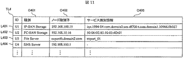
なお、ここで図11の説明を行うと、管理害IT装置管理テーブルTL3には発見した管理外IT装置の各々について以下の情報を含む。
(A)管理外IT装置の識別情報
(B)管理外IT装置の種別であるC401
(C)管理外IT装置の通信識別情報であるC402
(D)管理外IT装置のサービスにアクセスするために必要な識別情報であるC403
S120においては、管理外IT装置の識別情報を、該IT装置が管理外であることがわかるような印をつけた上で、図12に示すようにルール適用先管理テーブルTL1に格納する。本実施例では、ストレージ装置U3に関する管理外IT装置管理テーブルの情報を元に識別情報を、ルール適用先管理テーブルTL1に格納する。格納した後、選択したクライアント側のIT装置に対向するサーバ側のIT装置に関する検索情報が存在するかについてS8に戻る。
In addition, if FIG. 11 is demonstrated here, the management harm IT apparatus management table TL3 contains the following information about each unmanaged IT apparatus discovered.
(A) Identification information of unmanaged IT device (B) C401 which is the type of unmanaged IT device
(C) C402 which is communication identification information of an unmanaged IT device
(D) C403 which is identification information necessary for accessing the service of the unmanaged IT device
In S120, the identification information of the unmanaged IT device is stored in the rule application destination management table TL1 as shown in FIG. 12, after being marked so that the IT device is unmanaged. In this embodiment, the identification information is stored in the rule application destination management table TL1 based on the information in the unmanaged IT device management table regarding the storage device U3. After the storage, the process returns to S8 as to whether there is search information related to the server-side IT device opposite to the selected client-side IT device.
本実施例において、S108に戻ると、S107に於いて取得したサーバ側のストレージ装置に関する検索情報で未検索のものが存在するかを判断するが、計算機N10に関するサーバ側のストレージに関する検索情報は図8のL202の行が存在するため、S109に移る。 In this embodiment, when returning to S108, it is determined whether there is any unsearched search information related to the server-side storage apparatus acquired in S107. The search information related to the server-side storage related to the computer N10 is shown in FIG. Since there are eight L202 rows, the process proceeds to S109.
S109に移ると、L202に対応するストレージ装置を構成管理にて検索する。実施例では図9のように、L202に対応するストレージ装置が存在するため、L202に対するIT装置は管理対象であることがわかるので、S110において管理対象のIT装置であると判断してS120に移る。S120では、管理対象のIT装置としてストレージ装置N40と計算機N10のリストをルールR1の適用先IT装置として図11のルール適用先管理テーブルのL101に格納する。 In S109, the storage device corresponding to L202 is searched by configuration management. In the embodiment, as shown in FIG. 9, since there is a storage device corresponding to L202, it can be seen that the IT device for L202 is a management target, so in S110 it is determined that it is a management target IT device and the process moves to S120. . In S120, a list of the storage device N40 and the computer N10 as IT devices to be managed is stored in L101 of the rule application destination management table of FIG. 11 as an application destination IT device of rule R1.
以上のステップにより、計算機N10に対して論理ボリュームを提供している管理対象外のストレージ装置U1を含めてルールR1を適用できるようになる。 Through the above steps, the rule R1 can be applied to the unmanaged storage apparatus U1 that provides the logical volume to the computer N10.
次に図11のルール適用先管理テーブルを用いて、図2のS6の一例、つまり管理外のストレージ装置U1で障害が発生した場合に、前記ストレージ装置U1を障害の根本原因として画面表示する処理について説明する。 Next, using the rule application destination management table of FIG. 11, when a failure occurs in the example of S6 of FIG. 2, that is, the unmanaged storage device U1, the storage device U1 is displayed on the screen as the root cause of the failure. Will be described.
ストレージ装置U1からコントローラの障害イベントが発生し、図1のイベント解析処理部C12において図11のルール適用先管理テーブルを元にルールによるイベント相関によって障害の原因箇所を特定されると、解析結果の情報が、画面表示部C2に送信される。画面表示部C2では、図16のフローにもとづき、根本原因のIT装置が管理対象かどうかを判断して、適切な画面を画面表示装置M1に表示させる。 When a failure event of the controller occurs from the storage apparatus U1, and the cause of the failure is specified by event correlation based on the rule based on the rule application destination management table of FIG. 11 in the event analysis processing unit C12 of FIG. Information is transmitted to the screen display unit C2. The screen display unit C2 determines whether the root cause IT device is a management target based on the flow of FIG. 16, and displays an appropriate screen on the screen display device M1.
図16のステップ601から603において画面標示部C2において、図17に示したルールエンジンにおける障害解析の結果を示す障害解析結果データD1をルールエンジンC1から取得する。なお、ルールエンジンC1(特にイベント処理解析部C12)は図2のS4及び図4及び図5にて説明した処理を行っている。 In Steps 601 to 603 in FIG. 16, the screen marking unit C2 acquires failure analysis result data D1 indicating the result of failure analysis in the rule engine shown in FIG. 17 from the rule engine C1. Note that the rule engine C1 (particularly the event processing analysis unit C12) performs the processing described in S4 of FIG. 2, and FIGS.
障害解析結果データD1は、障害原因IT装置に関する情報である障害原因IT装置情報と、運用管理システムが受信した管理対象のIT装置のイベントに関する情報である受信イベントリストと、を含むデータから成る。障害原因IT装置情報D11は、障害原因IT装置を示す情報と、障害箇所の部位に関する情報を含む。障害箇所の部位に関する情報は、管理対象外のIT装置である障害原因IT装置からどの程度の障害情報を取得できるかによる。全く障害情報を取得できない場合には、図17のように不明となる。受信イベントリストは、この障害について定義されているルールにおいて、関連がある受信イベントに関する情報である、受信イベントの発信元に関する情報である受信イベント発信元と、イベントの内容に関する情報を示すイベント種別とを含む。 The failure analysis result data D1 is composed of data including failure cause IT device information that is information related to the failure cause IT device and a received event list that is information related to events of the management target IT device received by the operation management system. The failure cause IT device information D11 includes information indicating the failure cause IT device and information related to the location of the failure location. The information regarding the location of the fault location depends on how much fault information can be acquired from the fault-causing IT device that is an IT device that is not managed. When failure information cannot be acquired at all, it becomes unknown as shown in FIG. The received event list includes a received event source that is information related to a received event that is related to the received event in the rule defined for the failure, an event type that indicates information related to the content of the event, and including.
S604において、取得した障害解析結果データD11の障害原因IT装置の情報から、管理対象か管理対象外かを判断する。本実施例では管理対象外のIT装置であるため、S605に進む。 In step S604, it is determined from the information of the failure cause IT device in the acquired failure analysis result data D11 whether it is a management target or not. In this embodiment, since the IT apparatus is not a management target, the process proceeds to S605.
S605では、障害解析結果データD11の障害原因IT装置の情報を元に図11の管理外IT装置管理テーブルを検索して、該管理外IT装置に関する情報を取得してS606に進む。本実施例ではストレージ装置U1について図11のL401から取得する。 In S605, the non-managed IT device management table in FIG. 11 is searched based on the information of the failure cause IT device in the failure analysis result data D11, and information related to the unmanaged IT device is acquired, and the process proceeds to S606. In this embodiment, the storage device U1 is acquired from L401 in FIG.
S606では、S605にて取得した情報を含めて、発生した障害の根本原因が、管理外のIT装置が原因であることを画面に表示する。その際の画面の構成例は、図18のように、管理外IT装置が障害の根本原因であることを伝えるメッセージと、障害の原因について解析した結果である障害解析結果と、発生した障害に関して運用管理システムが検知している障害情報、例えば受信しているイベントなど、とを含んだウィンドウ、又はダイアログなど、画面表示を画面出力装置M1に出す。本実施例の管理外のIT装置であるストレージU1の障害が根本原因であるケースにおける画面表示例は、図19のようになる。障害原因IT装置が、管理対象外であることがわかる情報と、そのIT装置の種別が何であるか、例えばIP−SANストレージ装置であり、IT装置の識別情報として例えばIPアドレスが192.168.100.15であることを含むような画面表示である。 In S606, it is displayed on the screen that the root cause of the failure that has occurred is caused by an unmanaged IT device, including the information acquired in S605. As shown in FIG. 18, the configuration example of the screen at that time is related to a message that the unmanaged IT device is the root cause of the failure, a failure analysis result that is a result of analyzing the cause of the failure, and a failure that has occurred. A screen display such as a window or a dialog including failure information detected by the operation management system, for example, a received event, is output to the screen output device M1. An example of a screen display in the case where the failure of the storage U1, which is an unmanaged IT apparatus of the present embodiment, is the root cause is as shown in FIG. Information indicating that the failure-causing IT device is not a management target and what type of IT device is, for example, an IP-SAN storage device. For example, the IP address is 192.168 .. It is a screen display including that it is 100.15.
以上のステップにより、管理対象外IT装置のストレージ装置U1に障害があった場合に、ルールR1のようなIP−SANストレージの障害が管理対象外で起こった場合について適用できるようになり、根本原因が管理対象外のIP−SANストレージであることを画面に表示することができる。 With the above steps, when a failure occurs in the storage device U1 of the IT device that is not managed, it can be applied to a case where a failure of the IP-SAN storage such as rule R1 occurs outside the management subject, and the root cause Can be displayed on the screen that is an unmanaged IP-SAN storage.
(ルールR2についての処理フロー)
ルールR2について、図3のITシステムを対象とした実施例をもとにフローを説明する。
(Processing flow for rule R2)
A flow of the rule R2 will be described based on an embodiment for the IT system of FIG.
S101においてルールR2があるためS102に進み、S102では、ルールR2を読み込み、R2に読み込み済みの印をつける。S103において、ルールR2に記述されたトポロジ情報として図4の(2)のFC−SANトポロジとして、クライアント側にFibre ChannelのHost Bus Adapter、すなわちFcHbaT211を持つ計算機T21、FCスイッチT22を介して、サーバ側にFibre ChannelのポートであるFcPortT231を持つストレージ装置T23が接続されているトポロジを検索条件に定める。 Since there is a rule R2 in S101, the process proceeds to S102. In S102, the rule R2 is read, and R2 is marked as read. In S103, as the topology information described in the rule R2, as the FC-SAN topology of (2) in FIG. 4, the client channel Host Bus Adapter, that is, the computer T21 having FcHbaT211 via the FC switch T22 and the server via the FC switch T22. The topology to which the storage apparatus T23 having FcPortT231, which is the Fiber Channel port, is connected on the side is determined as a search condition.
S104において、クライアント側のIT装置として、FcHbaを持つ計算機である計算機N13が見つかったものとする。 In S104, it is assumed that a computer N13, which is a computer having FcHba, is found as an IT apparatus on the client side.
S105において、計算機N13が未選択なIT装置であるので、S106に進む。 In S105, since the computer N13 is an unselected IT device, the process proceeds to S106.
S106において、計算機N13を選択して、選択済みとする。 In S106, the computer N13 is selected to be already selected.
S107において、図13に示したように計算機N13より、接続先のサーバ側のストレージ装置のFibre ChannelのポートであるFC PortのWWNを示すConnectedFcPortWWN C502を収集する。 In S107, as shown in FIG. 13, Connected FcPortWWN C502 indicating the WWN of the FC Port, which is the Fiber Channel port of the storage device on the server side of the connection destination, is collected from the computer N13.
なお、図13のFC−SANストレージ装置の接続情報について説明すると、個々のIT装置に対応する情報として、接続先のストレージ装置が有するFibreChannelの通信識別情報を含む。 The connection information of the FC-SAN storage device in FIG. 13 will be described. As information corresponding to each IT device, Fiber Channel communication identification information included in the connection destination storage device is included.
S108において、計算機N13における接続先のストレージ装置に関する検索情報であるConnectedFcPortWWNについて、未検索であるためS109に進む。 In S108, the Connected FcPortWWN, which is the search information related to the storage device to which the computer N13 is connected, has not been searched, and the process advances to S109.
S109において、計算機N13で取得したConnectedFcPortWWNとして、L501行目のC502の値を用いて、構成管理において、このWWNをFcPortのWWNに持つストレージ装置を検索する。 In S109, using the value of C502 in the L501 line as the Connected FcPortWWN acquired by the computer N13, the storage management device having this WWN in the WWN of the FcPort is searched in the configuration management.
S110において、S109で検索の結果、図13のL501行目のC502の値をFcPortのWWNとして持つストレージが図14に示すように管理対象の構成情報には存在しなかったため、S111に進む。 In S110, as a result of the search in S109, the storage having the value of C502 in the L501 line in FIG. 13 as the WWN of FcPort does not exist in the configuration information to be managed as shown in FIG.
なお、ここで図14に含まれる情報を説明すると、当該情報にはストレージ装置を示す識別情報と、当該ストレージ装置が有するFibreChannelにおける通信識別情報を有する。 Here, the information included in FIG. 14 will be described. The information includes identification information indicating the storage device and communication identification information in the Fiber Channel included in the storage device.
S111において、発見済みのストレージ装置の中で、図13のL501行目のC502の値をFcPortのWWNとして持つストレージ装置U2を発見したため、S115に進む。 In S111, the storage apparatus U2 having the value of C502 in the L501 line in FIG. 13 as the WWN of FcPort is found among the discovered storage apparatuses, and the process proceeds to S115.
S115において、発見済みのストレージ装置U2を管理内に含めるように提案する画面を表示する。図10は、ルールR1における画面表示例であるが、画面表示の構成は基本的に同様であり、メッセージの中身が実際のIT装置のものに置き換わるのみである。 In S115, a screen for proposing to include the discovered storage apparatus U2 in the management is displayed. FIG. 10 shows an example of screen display according to the rule R1, but the configuration of the screen display is basically the same, and only the contents of the message are replaced with those of the actual IT device.
S116にて管理者よりストレージ装置U2の識別情報と当該装置を管理対象とする指示情報を受信する。 In S116, identification information of the storage apparatus U2 and instruction information for managing the apparatus are received from the administrator.
S117において、ユーザが管理対象に含めたかどうかを確認し、本実施例では管理対象に含めたためS118に進む。 In S117, it is confirmed whether or not the user is included in the management target. In this embodiment, since the user included in the management target, the process proceeds to S118.
S118において、管理対象として新たに追加したストレージ装置U2について、管理対象のIT装置として取得が必要な情報を収集する。管理対象として取得する情報は、イベント情報と構成管理情報である。 In S118, for the storage apparatus U2 newly added as a management target, information that needs to be acquired as a management target IT apparatus is collected. Information acquired as a management target is event information and configuration management information.
S121においては、ストレージ装置U2を管理対象のIT装置として、計算機N14とともにルールR2の適用先IT装置としてルール適用先管理テーブルに登録する。本ケースの例では図12に示したルールのカラムC101と、そのルールの適用先となるIT装置リストを格納するカラムC102から成る、テーブル状のデータ構造に登録する。 In S121, the storage apparatus U2 is registered as an IT apparatus to be managed in the rule application destination management table together with the computer N14 as an application destination IT apparatus of the rule R2. In this example, the data is registered in a table-like data structure including the column C101 of the rule shown in FIG. 12 and the column C102 that stores the IT device list to which the rule is applied.
以上により、ルールR2に対して、管理対象外のIT装置であるFC−SANストレージ装置の障害解析が従来のルールベースのイベント相関で行えるようになる。
なお、障害解析の結果データを元に、管理対象外のIT装置であるFC−SANストレージが障害の根本原因であると画面表示を出す処理については、ルールR1の管理対象外のIP−SANストレージを障害の根本原因であると画面表示した処理と同様にして図16のステップで行う。
As described above, the failure analysis of the FC-SAN storage device that is an IT device that is not a management target can be performed for the rule R2 by the conventional rule-based event correlation.
For the process of displaying a screen display indicating that the FC-SAN storage, which is an unmanaged IT device, is the root cause of the failure based on the failure analysis result data, the IP-SAN storage that is not managed by the rule R1 Is performed in the steps of FIG. 16 in the same manner as the process of displaying the screen as the root cause of the failure.
上記の処理ステップにより、ルールR2に対しても、管理対象外IT装置のストレージ装置U2に障害があった場合に、ルールR2のようなFC−SANストレージの障害が管理対象外で起こった場合について適用できるようになり、根本原因が管理対象外のFC−SANストレージであることを画面に表示することができる。
(ルールR3についての処理フロー)
ルールR3について、図3のITシステムを対象とした実施例をもとにフローを説明する。
As a result of the above processing steps, when a failure occurs in the storage device U2 of the unmanaged IT device even for the rule R2, a failure of the FC-SAN storage like the rule R2 occurs outside the management target. It can be applied, and it can be displayed on the screen that the root cause is the FC-SAN storage that is not managed.
(Processing flow for rule R3)
A flow of the rule R3 will be described based on an example of the IT system shown in FIG.
S101においてルールR3があるためS102に進み、S102では、ルールR3を読み込み、R103に読み込み済みの印をつける。S103において、ルールR3に記述されたトポロジ情報として図4の(3)のファイルサーバ・クライアントのトポロジとして、クライアント側に公開されているファイルシステムをマウントしていることを示すImportedFileShareT311を持つ計算機T31、IPスイッチT32を介して、サーバ側に他の計算機に公開しているファイルシステムを持つことを示すExportedFileShareT331を持つ計算機T33が接続されているトポロジを検索条件に定める。 Since there is a rule R3 in S101, the process proceeds to S102. In S102, the rule R3 is read, and R103 is marked as read. In S103, as the topology information described in the rule R3, as the topology of the file server / client of FIG. 4 (3), the computer T31 having the ImportedFileShareT311 indicating that the file system disclosed on the client side is mounted, The topology to which the computer T33 having the ExportFileShare T331 indicating that the server side has a file system open to other computers is connected to the server side via the IP switch T32.
S104において、図4の(3)のトポロジのクライアント側のIT装置として、図3の計算機N10が見つかったものとする。 In S104, it is assumed that the computer N10 in FIG. 3 is found as the client-side IT device in the topology of (3) in FIG.
S105において、検索されたクライアント側のIT装置として計算機N10があり、未選択であるため、S106に進む。 In S105, there is a computer N10 as the searched client-side IT device, and since it is not selected, the process proceeds to S106.
S106において、未選択のクライアント側のIT装置として図3の計算機N10を選択し、選択済みとする。 In S106, the computer N10 of FIG. 3 is selected as an unselected client-side IT apparatus, and is selected.
S107において、計算機N10と、図4の(3)のトポロジのサーバ側のIT装置として対向する計算機の検索情報として、どのファイルサーバの公開ファイルシステムをマウントしているかを示すImportedFileShareの情報を取得する。クライアント側から取得するファイルサーバに関する情報を管理するテーブルとして図15のようなクライアント側のコンピュータのカラムC701と、それに対応するファイルサーバに関する識別情報のカラムC702と、ファイルサーバの公開名に関するカラムC703を含むデータ構造、例えばテーブルなどで管理する。なお、クライアント側から取得するファイルサーバに関する情報は、予め構成情報として図15のテーブルで取得済みであっても構わないし、S7の処理においてクライアント側のIT装置から取得してきても構わない。すなわち取得するタイミングは、S107の処理が完了するまでに行われていればよい。 In S107, Information of SharedFileShare indicating which file server's public file system is mounted is acquired as search information of the computer facing the computer N10 as the IT device on the server side of the topology of (3) in FIG. . As a table for managing information on the file server acquired from the client side, a column C701 of the client side computer as shown in FIG. 15, a column C702 of identification information about the corresponding file server, and a column C703 about the public name of the file server are shown. It is managed by a data structure including, for example, a table. Information regarding the file server acquired from the client side may be acquired in advance in the table of FIG. 15 as configuration information, or may be acquired from the IT apparatus on the client side in the processing of S7. That is, the acquisition timing may be performed until the processing of S107 is completed.
なお、ここで図15に含まれる情報を説明すると、当該情報には個々のファイルサーバ毎に以下の情報を含む。
(A)ファイルサーバーのIT装置としての識別情報
(B)一つ以上のファイルサーバとしての識別情報と公開名
S108において、S107で取得したクライアント側のファイルサーバに関する情報は、図15のL701行であり、未検索であるためS9に進む。
Here, the information included in FIG. 15 will be described. The information includes the following information for each individual file server.
(A) Identification information of file server as IT device (B) Identification information and public name as one or more file servers In S108, information on the file server on the client side acquired in S107 is shown in line L701 in FIG. Since there is no search, the process proceeds to S9.
S109において、図15のL701行目のファイルサーバの識別情報のカラムC702の値、すなわちexportfs.domain2.comというFQDNを持つIT装置を検索する。 In S109, the value in the column C702 of the identification information of the file server on the L701 line in FIG. 15, that is, exportfs. domain2. Search for an IT device having a FQDN of “com”.
S110において、管理対象の構成情報T0の中にexportfs.domain2.comというFQDNを持つ計算機が存在しないことから、S111に進む。 In S110, exportfs.com is included in the configuration information T0 to be managed. domain2. Since there is no computer having the FQDN of “com”, the process proceeds to S111.
S111において、発見済みリソースの中にexportfs.domain2.com というFQDNを持つ計算機が存在しないことから、S112に進む。 In S111, the exportfs. domain2. Since there is no computer having the FQDN of “com”, the process proceeds to S112.
S112において、exportfs.domain2.comという計算機の発見を試みる。発見は、DNSサーバに問い合わせてIPアドレスを解決し、そのIPアドレスに対してpingによりか存在を確認した上で、telnet、又はssh、又はWindows(登録商標)のリモート接続などによりアクセスを試みる。本実施例では、exportfs.domain2.comに対するIPアドレスに対するpingは成功を返し、存在が確認できるが、そのサーバの認証情報を持たないため、その他のアクセスは失敗してログインできないものとしてS114に進む。 In S112, exportfs. domain2. try to find a computer called com. For discovery, the DNS server is inquired to resolve the IP address, and the existence of the IP address is confirmed by pinging, and then access is attempted by telnet, ssh, or Windows (registered trademark) remote connection. In the present embodiment, exportfs. domain2. The ping for the IP address to com returns success and the existence can be confirmed, but since it does not have the authentication information of the server, the other access fails and the process proceeds to S114 assuming that login is not possible.
S114において、発見したexportfs.domain2.comの計算機は、pingでの応答を返すものの、それ以外の情報が取得できず、管理対象とすることができないのでS119に進む。 In S114, the discovered exportfs. domain2. The com computer returns a response by ping, but cannot acquire other information and cannot be a management target, so the process proceeds to S119.
S119において、exportfs.domain2.comの計算機を図11の管理外IT装置管理テーブルに登録する。具体的には図10のL403のように、ファイルサーバ識別情報と、サービス識別情報にクライアント側で取得した情報を格納する。 In S119, exportfs. domain2. com is registered in the unmanaged IT device management table of FIG. Specifically, information acquired on the client side is stored in the file server identification information and the service identification information as indicated by L403 in FIG.
S120において、クライアント側の計算機N10とexportfs.domain2.comの計算機Uとのペアに対するルール適用情報を生成する。具体的には、図121のL107のように、ルールR3に対して、適用先IT装置リストに、計算機N10と管理外IT装置である計算機U3を登録する。 In S120, the client-side computer N10 and exportfs. domain2. The rule application information for the pair of com with the computer U is generated. Specifically, as in L107 of FIG. 121, the computer N10 and the computer U3 that is an unmanaged IT device are registered in the application IT device list for the rule R3.
以上により、計算機N10のファイルサーバである管理外のIT装置である計算機U3についても障害解析が行えるようになる。 As described above, the failure analysis can also be performed on the computer U3 that is an unmanaged IT apparatus that is a file server of the computer N10.
同様にして、S101からS104のステップにより、ルールR3についてクライアント側のIT装置として計算機N11が見つかった場合の実施形態の処理フローを説明する。S105からS107のステップにより、計算機N11に対するファイルサーバとして図15のL703の行に示したファイルサーバに関する情報を取得する。S109において管理対象のIT装置に図15のL703行で示されたファイルサーバは見つからないため、S111に進む。S111においては、発見済みのリソースの中に図15のL703行で示されたIPアドレスを持つ計算機U5が存在するので、S115に進む。 Similarly, the processing flow of the embodiment when the computer N11 is found as the client-side IT apparatus for the rule R3 by the steps from S101 to S104 will be described. Through the steps from S105 to S107, information regarding the file server indicated in the line of L703 in FIG. 15 is acquired as the file server for the computer N11. In S109, since the file server indicated by the line L703 in FIG. 15 is not found in the management target IT apparatus, the process proceeds to S111. In S111, since the computer U5 having the IP address indicated by the L703 line in FIG. 15 exists in the discovered resources, the process proceeds to S115.
S115において、計算機U5を管理対象に含めるように提案する画面を表示し、S116にてユーザ入力としてユーザが計算機U5を管理対象とする指示を受信する。 In S115, a screen for proposing to include the computer U5 as a management target is displayed, and in S116, the user receives an instruction for the computer U5 as a management target as a user input.
S117において、S116ユーザが計算機U5を管理対象とする指示を受信したため、S118に進む。 In S117, since the S116 user has received an instruction to manage the computer U5, the process proceeds to S118.
S118において、計算機U5を管理対象とするための情報として、発見済みリソースとして保持していたIT装置の識別情報、アクセスのための情報の他に、計算機U5の接続デバイスの構成情報と、稼動状態と、性能情報とを含む監視情報を取得して、構成管理C3の管理対象の構成情報T0に格納する。 In S118, as information for making the computer U5 a management target, in addition to the identification information of the IT device held as a discovered resource and the information for access, the configuration information of the connected device of the computer U5 and the operating state And the monitoring information including the performance information are stored in the configuration information T0 to be managed by the configuration management C3.
S121において、管理内IT装置として計算機N11をクライアント、計算機U5をファイルサーバとするトポロジに対してルールR3を適用できるように、図12のL108行目のようなデータ構造としてルールメモリに格納する。 In S121, the rule R3 is stored in the rule memory as a data structure as shown in the L108 line of FIG. 12 so that the rule R3 can be applied to the topology in which the computer N11 is the client and the computer U5 is the file server.
以上により、発見済みのIT装置で、なおかつ管理対象外であったファイルサーバの計算機U5に対する障害解析が、図2のフローにしたがって行え、画面表示部C2において図16のフローに行うことで、画面表示装置M1に障害原因を出力することができるようになる。 As described above, the failure analysis for the computer U5 of the file server that has been discovered and is not subject to management can be performed according to the flow of FIG. 2, and the screen display unit C2 performs the flow of FIG. The cause of the failure can be output to the display device M1.
(ルールR4についての処理フロー)
ルールR4について、図3のITシステムを対象とした実施例をもとにフローを説明する。
(Processing flow for rule R4)
A flow of the rule R4 will be described based on an example of the IT system shown in FIG.
S101からS104のステップにより、ルールR4についてクライアント側のIT装置として計算機N10を見つける。S105からS107のステップにより、計算機N10に対するDNSサーバの検索情報として、計算機N10よりDNSサーバのIPアドレス192.168.100.1を取得する。 S108からS110のステップにより、取得したIPアドレス192.168.100.1を利用して構成管理C3の管理対象の構成情報T0にDNSサーバが存在しないことを確認し、S111に進む。S111では、DNSサーバは発見済みIT装置ではないことを判断して、S112に進み、S112において実ITシステムからIPアドレス192.168.100.1のノードに対するアクセスを試みる。アクセスの結果、pingによるネットワーク到達が確認できたものの、認証情報を持たないためログインはできず、S114において管理対象とすることができないと判断してS119に進む。S119においては、IPアドレス192.168.100.1の計算機を管理対象外IT装置として図11のL404に示したようにDNSサーバとして識別情報U4で情報を格納・管理してS120に進む。S120において、クライアントの計算機N10と、DNSサーバである管理外のIT装置の計算機U4をルール4の適用先IT装置リストとして図12のL109行のように格納する。
Through the steps from S101 to S104, the computer N10 is found as an IT device on the client side for the rule R4. In steps S105 to S107, the DNS server IP address 192.168.100.1 is acquired from the computer N10 as DNS server search information for the computer N10. In steps S108 to S110, it is confirmed that there is no DNS server in the configuration information T0 to be managed by the configuration management C3 using the acquired IP address 192.168.100.1, and the process proceeds to S111. In S111, it is determined that the DNS server is not a discovered IT device, and the process proceeds to S112. In S112, an attempt is made to access the node having the IP address 192.168.100.1 from the real IT system. As a result of the access, although the network arrival by ping was confirmed, it is not possible to log in because it does not have authentication information, and in S114 it is determined that it cannot be a management target, and the process proceeds to S119. In S119, the computer with the IP address 192.168.100.1 is the non-management-target IT device, and the information is stored and managed as the DNS server with the identification information U4 as shown in L404 of FIG. 11, and the process proceeds to S120. In S120, the client computer N10 and the computer U4 of the unmanaged IT device that is the DNS server are stored as the application device list to which
以上のステップにより、管理外のDNSサーバである計算機U4の障害解析が、従来のルールによるイベント相関により解析できるようになり、障害原因として管理外のDNSサーバを特定することができるようになる。 Through the above steps, failure analysis of the computer U4 which is an unmanaged DNS server can be analyzed by event correlation based on the conventional rule, and an unmanaged DNS server can be specified as the cause of failure.
図3のそのほかのIT装置に対するルール4の適用についても同様にして、管理外のDNSサーバである計算機U4に対して適用情報が生成されることで行える。
Similarly, the application of the
また、他のルールの実施例と同様にして、図16のフローを画面表示部C2にて行うことで、管理外のIT装置であるDNSサーバが障害の根本原因であることを画面に表示することができる。 Further, in the same manner as in the other rule embodiments, the flow shown in FIG. 16 is performed on the screen display unit C2, thereby displaying on the screen that the DNS server, which is an unmanaged IT device, is the root cause of the failure. be able to.
本発明の第2の実施形態は、第1の実施形態において図2に示した障害解析の全体処理フローの処理手順を、図20に示したように、ルール適用部C11における適用情報を作成するステップS4bをイベント受信するステップS3bよりもあとで、なおかつイベント解析部C12におけるイベント解析処理のステップS5bよりも前のステップで行う。この第2実施形態と、第1実施形態の違いは、ルールの適用情報を作成するタイミングのみである。 In the second embodiment of the present invention, the processing procedure of the overall processing flow of the failure analysis shown in FIG. 2 in the first embodiment is created in the application information in the rule application unit C11 as shown in FIG. Step S4b is performed after step S3b for receiving an event and before step S5b of the event analysis process in the event analysis unit C12. The difference between the second embodiment and the first embodiment is only the timing of creating rule application information.
上記のように、ルールの適用情報のタイミングを変えて本発明を実施しても効果は損なわれず、管理対象外のIT装置を障害の根本原因装置であると画面に表示することは可能である。 As described above, even if the present invention is implemented by changing the timing of rule application information, the effect is not impaired, and it is possible to display an IT device that is not a management target on the screen as a root cause device of a failure. .
以上、本願明細書の実施例1と実施例2による複数の情報処理装置と画面出力装置とに接続され、プロセッサとメモリを有する運用管理サーバにおける前記複数の情報処理装置で発生するイベントの解析を実現するプログラムは以下の処理の一部または全てを有する。
(a)前記複数の情報処理装置の各々が、クライアントとしてネットワークサービスを用いるためにアクセス対象とする前記複数の情報処理装置の一部であるサーバ装置の識別情報を、前記メモリが有する構成情報に格納する構成情報格納処理。
(b)前記複数の情報処理装置の一部であって、前記運用管理サーバがイベント情報を取得する対象である複数のイベント取得対象装置を前記メモリが有する構成情報に登録する登録処理。
(c)前記複数の情報処理装置で発生する前記ネットワークサービスに関連した第一のイベント種別を含むイベントと、前記ネットワークサービスに関連した前記第一のイベント種別とは異なる第二のイベント種別を含むイベントと、を検知した場合に、前記第二のイベント種別に対応するイベントの発生が原因で前記第一のイベント種別に対応するイベントが発生し得ることを示す相関解析ルール情報を前記メモリに格納するルール格納処理。
(d)前記複数のイベント取得対象装置から収集した複数の前記イベント情報を前記メモリに格納するイベント格納処理。
(e)前記相関解析ルール情報を元に、前記メモリに格納した複数の前記イベント情報から、前記第一のイベント種別を含む第一のイベント情報を特定するイベント情報特定処理。
(f)前記構成情報を元に、前記第一のイベント情報を送信したイベント取得対象装置の一つである第一イベント取得対象装置と、前記第一のイベント種別に対応する前記ネットワークサービスにおける前記第一イベント取得対象装置のサーバ装置である障害要因装置とを特定する、要因特定処理。
(g)前記相関解析ルール情報と前記構成情報とを元に、前記障害要因装置が前記複数のイベント取得対象装置でない場合に、前記第一イベント取得対象装置と前記第一のイベント種別と前記障害要因装置と前記第二のイベント種別とを特定する情報を前記画面出力装置へ送信することで、前記第一イベント取得対象装置で発生した前記第一のイベント情報に対応したイベントが、前記障害要因装置で前記第二のイベント種別のイベントが発生したことが要因と推定されることを前記画面出力装置へ表示させる解析結果送信処理。
As described above, analysis of events occurring in the plurality of information processing devices in the operation management server connected to the plurality of information processing devices and the screen output device according to the first and second embodiments of the present specification and having a processor and a memory is performed. The realized program has a part or all of the following processing.
(A) In each of the plurality of information processing devices, identification information of a server device that is a part of the plurality of information processing devices to be accessed in order to use a network service as a client is used as configuration information included in the memory. Configuration information storage processing to be stored.
(B) Registration processing for registering a plurality of event acquisition target devices, which are a part of the plurality of information processing devices and from which the operation management server acquires event information, in configuration information included in the memory.
(C) including an event including a first event type related to the network service generated in the plurality of information processing apparatuses and a second event type different from the first event type related to the network service Correlation analysis rule information indicating that an event corresponding to the first event type can occur due to the occurrence of an event corresponding to the second event type when the event is detected is stored in the memory. Rule storage process.
(D) Event storage processing for storing a plurality of pieces of event information collected from the plurality of event acquisition target devices in the memory.
(E) Event information specifying processing for specifying first event information including the first event type from the plurality of event information stored in the memory based on the correlation analysis rule information.
(F) Based on the configuration information, the first event acquisition target device that is one of the event acquisition target devices that transmitted the first event information, and the network service corresponding to the first event type Factor identification processing for identifying a failure factor device that is a server device of the first event acquisition target device.
(G) Based on the correlation analysis rule information and the configuration information, when the failure factor device is not the plurality of event acquisition target devices, the first event acquisition target device, the first event type, and the failure By transmitting information identifying the factor device and the second event type to the screen output device, the event corresponding to the first event information generated in the first event acquisition target device is the failure factor. Analysis result transmission processing for displaying on the screen output device that it is presumed that the occurrence of the event of the second event type is caused in the device.
さらには、前記相関解析ルール情報は、前記第一のイベント種別が発生した前記複数の情報処理装置の一つである第一情報処理装置と、前記第二のイベント種別が発生した前記複数の情報処理装置の一つである第二情報処理装置と、の間のトポロジ条件を示すトポロジ条件情報を含み、前記要因特定ステップは、前記トポロジ条件情報に基づいて前記障害要因装置を特定してもよい。このような処理によってイベントが発生した情報処理装置が実際に用いている情報処理装置に限定して推定を提示できるため、より運用管理サーバの利用者に利便性の高い。 Further, the correlation analysis rule information includes a first information processing device that is one of the plurality of information processing devices in which the first event type has occurred, and the plurality of information in which the second event type has occurred. Topology condition information indicating a topology condition between the second information processing apparatus that is one of the processing apparatuses may be included, and the factor specifying step may specify the failure factor apparatus based on the topology condition information . Since the information processing apparatus in which an event has occurred by such a process can present an estimation limited to the information processing apparatus actually used, it is more convenient for the user of the operation management server.
また、運用管理サーバは以下の処理を有してもよい。
(h)前記相関解析ルール情報と前記構成情報に基づいて、前記複数のイベント取得対象装置のサーバ装置であって、前記複数のイベント取得対象装置に含まれない、前記複数の情報処理装置の一部であるイベント関連情報処理装置を特定する、関連装置特定処理。
(i)前記イベント関連情報処理装置からイベント情報の取得が可能か調査する、イベント情報取得可否調査処理。
(j)前記調査の結果を元に、前記イベント関連情報処理装置からイベント情報の取得が可能な場合は前記イベント関連情報処理装置を特定する情報を前記画面出力装置へ送信することで、前記イベント関連情報処理装置からイベント情報の取得が可能であることを前記画面出力装置へ表示させる、イベント情報取得対象追加提案処理。
Further, the operation management server may have the following processing.
(H) Based on the correlation analysis rule information and the configuration information, the server device of the plurality of event acquisition target devices, the one of the plurality of information processing devices not included in the plurality of event acquisition target devices Related device identification processing for identifying an event-related information processing device that is a section.
(I) Event information acquisition possibility investigation processing for investigating whether event information can be obtained from the event-related information processing apparatus.
(J) Based on the result of the investigation, when event information can be acquired from the event-related information processing device, information identifying the event-related information processing device is transmitted to the screen output device, so that the event Event information acquisition target addition proposal processing for displaying on the screen output device that event information can be acquired from the related information processing device.
このような処理は、情報処理装置の管理者または管理方法の変更によって新たに運用管理サーバでイベント監視が必要または可能となった時点から迅速に、登録忘れをせずに運用管理サーバへの登録を促進することができる。 Such processing can be performed quickly and without forgetting to register from the time when event monitoring is newly required or possible on the operation management server due to changes in the information processing device administrator or management method. Can be promoted.
さらには、前記イベント情報取得可否調査処理は、前記複数の情報処理装置であって予め調査範囲として設定されたIPアドレスの範囲に含まれるIPアドレスを有する情報処理装置に対して、前記運用管理サーバが所定の手順に基づくアクセスを行った結果に基づいてもよい。情報処理装置(特にインターネットを介してアクセスするサーバ計算機)には不正アクセスや不正攻撃を防止するために当該装置外部からのアクセスを監視している場合があり、当該調査処理によるアクセスを行った場合もアクセス監視により不正アクセスや不正攻撃と見なされることがある。そのため、明らかにイベント監視の対象としない情報処理装置のIPアドレス、またはイベント監視対象になりうる情報処理装置のIPアドレスの範囲を特定することで、こうした不正アクセスや不正攻撃と誤認されるような通信を抑止することができる。 Further, the event information acquisition possibility investigation processing is performed on the operation management server with respect to an information processing apparatus having an IP address included in a range of IP addresses set in advance as the investigation range. May be based on the result of access based on a predetermined procedure. When an information processing device (especially a server computer accessed via the Internet) is monitored for access from outside the device in order to prevent unauthorized access and attacks, and when access is made by the investigation process May be regarded as unauthorized access or unauthorized attack by access monitoring. Therefore, by identifying the IP address of an information processing device that is obviously not subject to event monitoring, or the range of IP addresses of information processing devices that can be subject to event monitoring, it is misidentified as such unauthorized access or unauthorized attack. Communication can be suppressed.
さらには、前記障害要因装置はコントローラを有し、論理ボリュームを提供するストレージ装置であって、前記ネットワークサービスは前記論理ボリュームをブロックアクセス形式のプロトコル(例えばFibreChannelやiSCSIがある)によって提供するサービスであって、前記第一のイベント種別が前記ストレージ装置の障害発生であり、前記第一のイベント種別が前記論理ボリュームへのアクセス失敗であってもよい。 Furthermore, the failure factor device is a storage device that has a controller and provides a logical volume, and the network service is a service that provides the logical volume by a block access type protocol (for example, Fiber Channel or iSCSI). The first event type may be a failure of the storage apparatus, and the first event type may be an access failure to the logical volume.
さらには、前記障害要因装置は前記ネットワークサービスとしてDNSを提供する計算機であって、前記第一のイベント種別がDNS要求失敗であり、前記第一のイベント種別がDNSサーバの通信断絶であってもよい。 Further, the failure factor device is a computer that provides DNS as the network service, wherein the first event type is a DNS request failure and the first event type is a DNS server communication interruption. Good.
さらには、前記障害要因装置は前記複数の情報処理装置の少なくとも一つからデータを受信するNICを有し、格納したファイルを前記複数の情報処理装置の少なくとも一つに提供するファイルサーバ計算機であって、前記ネットワークサービスは前記ファイルサーバ計算機が格納したファイルを共有するネットワークファイル共有サービスであって、前記第一のイベント種別が前記ファイルサーバの障害発生(例えばNICの障害発生、ファイルサーバが有するプロセッサが実行するソフトウェアの不具合の発生、その他ファイルサーバの通信機能が停止する障害の発生)であり、前記第一のイベント種別が前記ネットワークファイル共有サービスで提供されたファイルへのアクセス失敗であってもよい。 Further, the failure factor device is a file server computer having a NIC that receives data from at least one of the plurality of information processing devices and providing a stored file to at least one of the plurality of information processing devices. The network service is a network file sharing service for sharing files stored in the file server computer, and the first event type is the occurrence of a failure of the file server (for example, the occurrence of a NIC failure, the processor of the file server) Even if the first event type is a failure to access the file provided by the network file sharing service) Good.
さらには、前記相関解析ルール情報と前記構成情報とを元に、前記障害要因装置が前記複数のイベント取得対象装置の一つの場合に、複数の前記イベント情報から前記第二のイベント種別を含み、前記障害要因装置が取得元である第二のイベント情報を特定し、前記第一イベント取得対象装置と前記第一のイベント情報と前記障害要因装置と前記第二のイベント情報とを特定する情報を前記画面出力装置へ送信することで、前記第一イベント取得対象装置で発生した前記第一のイベント情報に対応したイベントが、前記障害要因装置で発生した前記第二のイベント情報に対応したイベントが発生したことが要因であることを前記画面出力装置へ表示させてもよい。 Furthermore, based on the correlation analysis rule information and the configuration information, when the failure factor device is one of the plurality of event acquisition target devices, the plurality of event information includes the second event type, Identifying the second event information from which the failure factor device is the acquisition source, and information identifying the first event acquisition target device, the first event information, the failure factor device, and the second event information; By transmitting to the screen output device, an event corresponding to the first event information generated in the first event acquisition target device is an event corresponding to the second event information generated in the failure factor device. It may be displayed on the screen output device that the occurrence is a factor.
さらには、前記第一情報処理装置が計算機であり、前記第二情報処理装置がストレージ装置であり、前記トポロジ条件情報は、前記計算機と前記ストレージ装置とが接続するトポロジの接続関係を示す、前記計算機に対応する通信識別情報と前記ストレージ装置に対応する通信識別情報との組み合わせを含めても良い。なお、これら通信識別情報としてはiSCSI名と、IPアドレスと、FibreChannelにおけるWWNとの少なくとも一つが考えられる。 Further, the first information processing device is a computer, the second information processing device is a storage device, and the topology condition information indicates a connection relationship of a topology in which the computer and the storage device are connected. A combination of communication identification information corresponding to a computer and communication identification information corresponding to the storage device may be included. The communication identification information may be at least one of an iSCSI name, an IP address, and a WWN in Fiber Channel.
さらには、前記第一情報処理装置が計算機であり、前記第二情報処理装置はファイル共有サービスによって格納したファイルを前記複数の情報処理装置へ提供するファイルサーバ計算機であり、前記トポロジ条件情報は、前記計算機と前記ファイルサーバ計算機とが接続するトポロジの接続関係を示す前記計算機に対応する通信識別情報と前記ファイルサーバ計算機に対応する通信識別情報又は前記ファイルを公開するエクスポート名との組み合わせを含めても良い。 Further, the first information processing apparatus is a computer, the second information processing apparatus is a file server computer that provides a file stored by a file sharing service to the plurality of information processing apparatuses, and the topology condition information is: Including a combination of communication identification information corresponding to the computer indicating a topology connection relationship between the computer and the file server computer, and communication identification information corresponding to the file server computer or an export name for publishing the file Also good.
さらには、前記第一情報処理装置は計算機であり、前記第二情報処理装置がネットワーク共有サービスとしてDNSを前記複数の情報処理装置に提供するDNSサーバ計算機であり、前記トポロジ条件情報は、前記計算機と前記DNSサーバ計算機とが接続するトポロジの接続関係を示す前記計算機に対応する通信識別情報と前記DNSサーバ計算機に対応する通信識別情報との組み合わせを含めても良い。なお、前記計算機に対応する通信識別情報と前記DNSサーバ計算機に対応する通信識別情報とは、IPアドレス又はFQDNが考えられる。 Furthermore, the first information processing apparatus is a computer, the second information processing apparatus is a DNS server computer that provides a DNS as a network sharing service to the plurality of information processing apparatuses, and the topology condition information is stored in the computer. And a combination of communication identification information corresponding to the computer indicating a connection relationship of a topology connected to the DNS server computer and communication identification information corresponding to the DNS server computer. The communication identification information corresponding to the computer and the communication identification information corresponding to the DNS server computer may be IP addresses or FQDNs.
さらには、前記運用管理サーバは一つ以上の計算機から構成されてもよい。 Furthermore, the operation management server may be composed of one or more computers.
N0...運用管理サーバ
N1乃至N3...計算機
N4...ネットワーク(NW)スイッチ
N5...ストレージ装置
O1...計算機
O2...NWスイッチ
O3...ストレージ装置
M1...画面出力装置
N0. . . Operation management servers N1 to N3. . . Calculator N4. . . Network (NW) switch N5. . . Storage device O1. . . Calculator O2. . . NW switch O3. . . Storage device M1. . . Screen output device
Claims (28)
前記複数のイベント取得対象装置から収集した複数のイベント情報を格納するイベント格納ステップと、
前記ネットワークサービスに関連した第一のイベント種別とは異なる第二のイベント種別に対応するイベントの発生が原因で前記第一のイベント種別に対応するイベントが発生し得ることを示す相関解析ルール情報を元に、格納済みの前記複数のイベント情報から、前記第一のイベント種別を含む第一のイベント情報を特定するイベント情報特定ステップと、
情報処理装置と情報処理装置の接続先の関係を表す構成情報を元に、前記第一のイベント情報を送信した第一イベント取得対象装置と、前記第一イベント取得対象装置に接続されているサーバ装置である障害要因装置とを特定する要因特定ステップと、
前記相関解析ルール情報と、前記構成情報とを元に、前記障害要因装置が前記複数のイベント取得対象装置でない装置である対象外装置の場合に、前記第一のイベント情報が表すイベントの要因が前記第二のイベント種別に対応したイベントが前記障害要因装置で発生したことであると推定されることを意味する情報を表示させる第一表示ステップと、
を前記運用管理サーバに実行させることを特徴としたプログラム。 A plurality of information processing devices each including a plurality of event acquisition target devices, each of which is a target for acquiring event information, and a server device that is a target device that is not the plurality of event acquisition devices and that provides a network service A program executed on the operation management server to be managed,
An event storage step for storing a plurality of pieces of event information collected from the plurality of event acquisition target devices;
Correlation analysis rule information indicating that an event corresponding to the first event type can occur due to the occurrence of an event corresponding to the second event type different from the first event type related to the network service. Originally, from the plurality of stored event information, an event information specifying step for specifying first event information including the first event type,
A first event acquisition target device that has transmitted the first event information based on configuration information representing a relationship between a connection destination of the information processing device and the information processing device, and a server connected to the first event acquisition target device A factor identifying step for identifying a fault factor device which is a device;
Based on the correlation analysis rule information and the configuration information, when the failure factor device is a non-target device that is not the plurality of event acquisition target devices, the event factor represented by the first event information is A first display step of displaying information meaning that an event corresponding to the second event type is estimated to have occurred in the failure factor device ;
A program, wherein Rukoto is executed by the management server.
前記相関解析ルール情報は、前記第一のイベント種別に対応したイベントが発生した前記情報処理装置の一つである第一情報処理装置と、前記第二のイベント種別に対応したイベントが発生した前記情報処理装置の一つである第二情報処理装置と、の間のトポロジ条件を示すトポロジ条件情報を含み、
前記要因特定ステップは、前記トポロジ条件情報に基づいて前記障害要因装置を特定する、
ことを特徴としたプログラム。 The program according to claim 1,
The correlation analysis rule information, the said the first information processing apparatus which is one of the information processing apparatus first event corresponding to the event type occurs, an event corresponding to the second event type occurs Including topology condition information indicating a topology condition between the second information processing apparatus, which is one of the information processing apparatuses,
The factor identifying step identifies the failure factor device based on the topology condition information.
A program characterized by that.
前記相関解析ルール情報と前記構成情報に基づいて、前記対象外装置を特定する対象外装置特定ステップと、
前記対象外装置からイベント情報の取得が可能か調査する調査ステップと、
前記対象外装置からイベント情報の取得が可能な場合は、前記対象外装置からイベント情報の取得が可能であることを表示させる追加提案ステップと、
を前記運用管理サーバに実行させることを特徴としたプログラム。 A program according to claim 2, wherein
On the basis of the correlation analysis rule information and the configuration information, a non-target device specifying step of specifying the target out of the apparatus,
An investigation step of investigating whether event information can be acquired from the non-target device;
If it is possible to acquire the event information from the non-target unit, the additional proposed step of displaying that it is possible to acquire the event information from the non-target unit,
Is executed by the operation management server .
前記調査ステップは、予め調査範囲として設定されたIPアドレスの範囲に含まれるIPアドレスを有する情報処理装置に対して、前記運用管理サーバが所定の手順に基づくアクセスを行った結果に基づく、
ことを特徴としたプログラム。 A program according to claim 3, wherein
The investigation step is based on a result of the operation management server performing an access based on a predetermined procedure with respect to an information processing apparatus having an IP address included in an IP address range set in advance as an investigation range .
A program characterized by that.
前記障害要因装置は、コントローラを有し論理ボリュームを提供するストレージ装置であって、
前記ネットワークサービスは、前記論理ボリュームをブロックアクセス形式のプロトコルによって提供するサービスであって、
前記第二のイベント種別に対応するイベントの発生が、前記ストレージ装置の障害発生であり、
前記第一のイベント種別に対応するイベントが、前記論理ボリュームへのアクセス失敗である、
ことを特徴としたプログラム。 The program according to claim 1,
The failure factor device is a storage device having a controller and providing a logical volume,
The network service, the logical volume A service provided by a block access type protocol,
Occurrence of an event corresponding to the second event type is the failure of the storage device,
The event corresponding to the first event type is an access failure to the logical volume.
A program characterized by that.
前記ブロックアクセス形式のプロトコルは、Fibre Channel又はiSCSIである
ことを特徴としたプログラム。 A program according to claim 5, wherein
The block access format protocol is Fiber Channel or iSCSI.
前記障害要因装置は、前記ネットワークサービスとしてDNSを提供する計算機であって、
前記第一のイベント種別に対応するイベントが、DNS要求失敗であり、
前記第二のイベント種別に対応するイベントが、DNSサーバの通信断絶である、
ことを特徴としたプログラム。 The program according to claim 1,
The fault factor device is a computer that provides DNS as said network service,
The event corresponding to the first event type is a DNS request failure,
The event corresponding to the second event type is a DNS server communication interruption.
A program characterized by that.
前記障害要因装置は、格納したファイルを前記複数の情報処理装置の少なくとも一つに提供するファイルサーバ計算機であって、
前記ネットワークサービスは、前記ファイルサーバ計算機が格納したファイルを共有するネットワークファイル共有サービスであって、
前記第二のイベント種別に対応したイベントが、前記ファイルサーバ計算機の障害発生であり、
前記第一のイベント種別に対応したイベントが、前記ネットワークファイル共有サービスで提供されたファイルへのアクセス失敗である、
ことを特徴としたプログラム。 The program according to claim 1,
The fault factor device is a file server computer which provides the stored file to at least one of the plurality of information processing apparatuses,
It said network service is a network file sharing service for sharing files that the file server computer has stored,
Event corresponding to the second event type is the failure of the file server computer,
Events corresponding to the first event type is an access failure to that provided file in the network file sharing service,
A program characterized by that.
前記障害要因装置が前記複数のイベント取得対象装置のうちの1つである場合は、前記相関解析ルール情報と前記構成情報とに基づいて、複数の前記イベント情報から前記第二のイベント種別に対応したイベントを表し前記障害要因装置が取得元である第二のイベント情報を特定し、前記第一イベント取得対象装置で発生した前記第一のイベント情報が表すイベントが発生した要因が、前記障害要因装置で発生した前記第二のイベント情報に対応したイベントが発生したことであることを表示させる第二表示ステップ、
を前記運用管理サーバに実行させることを特徴としたプログラム。 The program according to claim 1,
If the fault factor device is one of the plurality of event acquisition target device, on the basis of the correlation analysis rule information and the configuration information, corresponding plurality of the event information to the second event type The second event information representing the acquired event is specified as the acquisition source, and the cause of the event represented by the first event information generated in the first event acquisition target device is the failure factor. A second display step for displaying that an event corresponding to the second event information generated in the device has occurred;
Is executed by the operation management server .
前記第一情報処理装置が、計算機であり、
前記第二情報処理装置が、ストレージ装置であり、
前記トポロジ条件情報は、前記計算機と前記ストレージ装置とが接続するトポロジの接続関係を示す、前記計算機に対応する通信識別情報と前記ストレージ装置に対応する通信識別情報との組み合わせ、を含む、
ことを特徴としたプログラム。 A program according to claim 2, wherein
The first information processing apparatus is a computer;
The second information processing apparatus is a storage apparatus;
The topology condition information includes a combination of the communication identification information, wherein the computer showing the connection relationships of the topology storage device and is connected, corresponds to the communication identification information and the storage device corresponding to said computer,
A program characterized by that.
前記計算機に対応する計算機通信識別情報と前記ストレージ装置に対応する通信識別情報とは、iSCSI名と、IPアドレスと、FibreChannelにおけるWWNとの少なくとも一つである
ことを特徴とするプログラム。 A program according to claim 10, wherein
The computer communication identification information corresponding to the computer and the communication identification information corresponding to the storage device are at least one of an iSCSI name, an IP address, and a WWN in Fiber Channel.
前記第一情報処理装置が、計算機であり、
前記第二情報処理装置は、ファイル共有サービスによって格納したファイルを前記複数の情報処理装置へ提供するファイルサーバ計算機であり、
前記トポロジ条件情報は、前記計算機と前記ファイルサーバ計算機とが接続するトポロジの接続関係を示す、前記計算機に対応する通信識別情報と前記ファイルサーバ計算機に対応する通信識別情報又は前記ファイルを公開するエクスポート名との組み合わせ、を含む、
ことを特徴としたプログラム。 A program according to claim 2, wherein
The first information processing apparatus is a computer;
It said second information processing apparatus is a file server computer that provides file stored by the file sharing service to the plurality of information processing apparatuses,
Export the topology condition information indicates a connection relationship of topologies said computer and said file server computer is connected, to publish a communication identification information or the file corresponding to the file server computer and the communication identification information corresponding to the computer Including combinations with names,
A program characterized by that.
前記第一情報処理装置は計算機であり、前記第二情報処理装置がネットワーク共有サービスとしてDNSを前記複数の情報処理装置に提供するDNSサーバ計算機であり、
前記トポロジ条件情報は、前記計算機と前記DNSサーバ計算機とが接続するトポロジの接続関係を示す、前記計算機に対応する通信識別情報と前記DNSサーバ計算機に対応する通信識別情報との組み合わせ、を含む、
ことを特徴としたプログラム。 A program according to claim 2, wherein
The first information processing apparatus is a computer, and the second information processing apparatus is a DNS server computer that provides DNS to the plurality of information processing apparatuses as a network sharing service,
The topology condition information includes a combination of the communication identification information and said computer and said DNS server computer indicating a connection relationship topology connection, corresponds to the communication identification information and the DNS server computer corresponding to the computer,
A program characterized by that.
前記計算機に対応する通信識別情報と前記DNSサーバ計算機に対応する通信識別情報とは、IPアドレス又はFQDNである、
ことを特徴としたプログラム。 14. The program according to claim 13, wherein
The communication identification information corresponding to the computer and the communication identification information corresponding to the DNS server computer are an IP address or an FQDN.
A program characterized by that.
前記メモリは、
前記ネットワークサービスに関連した第一のイベント種別とは異なる第二のイベント種別に対応するイベントの発生が原因で前記第一のイベント種別に対応するイベントが発生し得ることを示す相関解析ルール情報と、
情報処理装置と情報処理装置の接続先との関係を表す構成情報と、
を記憶し、
前記プロセッサは、
(a)前記複数のイベント取得対象装置から収集した複数のイベント情報を格納し、
(b)前記相関解析ルール情報を元に、格納済みの前記複数のイベント情報から、前記第一のイベント種別を含む第一のイベント情報を特定し、
(c)前記構成情報を元に、前記第一のイベント情報を送信した第一イベント取得対象装置と、前記第一イベント取得対象装置に接続されているサーバ装置である障害要因装置とを特定し、
(d)前記相関解析ルール情報と、前記構成情報とを元に、前記障害要因装置が前記複数のイベント取得対象装置でない装置である対象外装置の場合に、前記第一のイベント情報が表すイベントの要因が前記第二のイベント種別に対応したイベントが前記障害要因装置で発生したことであると推定されることを意味する情報を表示させる、
を実行する、
ことを特徴とした運用管理サーバ。 A plurality of information processing devices each including a plurality of event acquisition target devices, each of which is a target for acquiring event information, and a server device that is a target device that is not the plurality of event acquisition devices and that provides a network service An operation management server that manages and has a processor and a memory,
The memory is
Correlation analysis rule information indicating that an event corresponding to the first event type may occur due to an occurrence of an event corresponding to a second event type different from the first event type related to the network service; ,
Configuration information representing the relationship between the information processing apparatus and the connection destination of the information processing apparatus;
Remember
The processor is
(A) storing a plurality of event information collected from the plurality of event acquisition target devices;
(B) the based on the correlation analysis rule information, from the stored plurality of event information, and identifies the first event information including the first event type,
(C) based on the configuration information to identify a first event acquisition target apparatus which has transmitted the first event information, and a failure factor device is a server device connected to the first event acquisition target device ,
(D) Based on the correlation analysis rule information and the configuration information, the event represented by the first event information when the failure factor device is a non-target device that is not the plurality of event acquisition target devices. Events factors are corresponding to the second event type to display the information indicating that this is supposed to be that generated by the fault factor device,
To run,
An operation management server characterized by that .
前記相関解析ルール情報は、前記第一のイベント種別に対応したイベントが発生した前記情報処理装置である第一情報処理装置と、前記第二のイベント種別に対応したイベントが発生した前記情報処理装置の一つである第二情報処理装置と、の間のトポロジ条件を示すトポロジ条件情報を含み、
前記プロセッサは、前記(c)の処理において、前記トポロジ条件情報に基づいて前記障害要因装置を特定する、
ことを特徴とした運用管理サーバ。 The operation management server according to claim 15,
The correlation analysis rule information includes a first information processing device that is the information processing device in which an event corresponding to the first event type has occurred, and the information processing device in which an event corresponding to the second event type has occurred. Including topology condition information indicating a topology condition between the second information processing apparatus that is one of
The processor identifies the failure factor device based on the topology condition information in the process of (c) ,
An operation management server characterized by that.
前記プロセッサが、
(f)前記相関解析ルール情報と前記構成情報に基づいて、前記対象外装置を特定し、
(g)前記対象外装置からイベント情報の取得が可能か調査し、
(h)前記対象外装置からイベント情報の取得が可能な場合は、前記対象外装置からイベント情報の取得が可能であることを表示させる、
ことを特徴とした運用管理サーバ。 An operation management server according to claim 16, wherein
The processor is
(F) on the basis of the correlation analysis rule information and the configuration information to identify the exempt device,
(G) to investigate whether it is possible to acquire the event information from the non-target unit,
(H) If it is possible to acquire the event information from the non-target device displays the from the non-target unit is capable of acquiring the event information,
An operation management server characterized by that.
前記(h)の調査は、予め調査範囲として設定されたIPアドレスの範囲に含まれるIPアドレスを有する情報処理装置に対して、所定の手順に基づくアクセスを行った結果に基づく、
ことを特徴とした運用管理サーバ。 An operation management server according to claim 17, wherein
The investigation of (h) is based on the result of performing an access based on a predetermined procedure for an information processing apparatus having an IP address included in the IP address range set in advance as the investigation range .
An operation management server characterized by that.
前記障害要因装置は、コントローラを有し、論理ボリュームを提供するストレージ装置であって、
前記ネットワークサービスは、前記論理ボリュームをブロックアクセス形式のプロトコルによって提供するサービスであって、
前記第二のイベント種別に対応したイベントが、前記ストレージ装置の障害発生であり、前記第一のイベント種別に対応したイベントが、前記論理ボリュームへのアクセス失敗である、
ことを特徴とした運用管理サーバ。 The operation management server according to claim 15,
The failure factor device is a storage device having a controller and providing a logical volume,
The network service, the logical volume A service provided by a block access type protocol,
The second event type corresponding to the event, said a failure of the storage device, an event corresponding to the first event type is an access failure to the logical volume,
An operation management server characterized by that.
前記ブロックアクセス形式のプロトコルは、FibreChannel又はiSCSIである
ことを特徴とした運用管理サーバ。 The operation management server according to claim 19,
Said block access type protocol, system management server that is characterized by a FibreChannel or iSCSI.
前記障害要因装置は、前記ネットワークサービスとしてDNSを提供する計算機であって、
前記第一のイベント種別に対応したイベントが、DNS要求失敗であり、
前記第二のイベント種別に対応したイベントが、DNSサーバの通信断絶である、
ことを特徴とした運用管理サーバ。 The operation management server according to claim 15,
The fault factor device is a computer that provides DNS as said network service,
The event corresponding to the first event type is a DNS request failure,
The event corresponding to the second event type is a DNS server communication interruption.
An operation management server characterized by that.
前記障害要因装置は、格納したファイルを前記複数の情報処理装置の少なくとも一つに提供するファイルサーバ計算機であって、
前記ネットワークサービスは、前記ファイルサーバ計算機が格納したファイルを共有するネットワークファイル共有サービスであって、
前記第二のイベント種別に対応したイベントが、前記ファイルサーバ計算機の障害発生であり、
前記第一のイベント種別に対応したイベントが、前記ネットワークファイル共有サービスで提供されたファイルへのアクセス失敗である、
ことを特徴とした運用管理サーバ。 The operation management server according to claim 15,
The fault factor device is a file server computer which provides the stored file to at least one of the plurality of information processing apparatuses,
It said network service is a network file sharing service for sharing files that the file server computer has stored,
Event corresponding to the second event type is the failure of the file server computer,
Events corresponding to the first event type is an access failure to that provided file in the network file sharing service,
An operation management server characterized by that.
前記プロセッサは、
前記障害要因装置が、前記複数のイベント取得対象装置のうちの1つである場合は、前記相関解析ルール情報と前記構成情報とに基づいて、複数の前記イベント情報から前記第二のイベント種別に対応したイベントを表し前記障害要因装置が取得元である第二のイベント情報を特定し、前記第一イベント取得対象装置で発生した前記第一のイベント情報が表すイベントが発生した要因が、前記障害要因装置で発生した前記第二のイベント情報に対応したイベントが発生したであることを表示させる、
ことを特徴とした運用管理サーバ。 The operation management server according to claim 15,
The processor is
The fault factor device, one in the case of one of said plurality of event acquisition target device, on the basis of the correlation analysis rule information and the configuration information, the second event type from the plurality of event information The second event information representing the corresponding event that is the acquisition source of the failure factor device is specified, and the cause of the event represented by the first event information that occurred in the first event acquisition target device is the failure Displaying that an event corresponding to the second event information generated in the factor device has occurred,
An operation management server characterized by that.
前記第一情報処理装置が、計算機であり、
前記第二情報処理装置が、ストレージ装置であり、
前記トポロジ条件情報は、前記計算機と前記ストレージ装置とが接続するトポロジの接続関係を示す、前記計算機に対応する通信識別情報と前記ストレージ装置に対応する通信識別情報との組み合わせ、を含む、
ことを特徴とした運用管理サーバ。 An operation management server according to claim 16, wherein
The first information processing apparatus is a computer;
The second information processing apparatus is a storage apparatus;
The topology condition information includes a combination of the communication identification information, wherein the computer showing the connection relationships of the topology storage device and is connected, corresponds to the communication identification information and the storage device corresponding to said computer,
An operation management server characterized by that.
前記計算機に対応する計算機通信識別情報と前記ストレージ装置に対応する通信識別情報とは、iSCSI名と、IPアドレスと、FibreChannelにおけるWWNとの少なくとも一つである
ことを特徴とする運用管理サーバ。 An operation management server according to claim 24, wherein
The operation management server characterized in that the computer communication identification information corresponding to the computer and the communication identification information corresponding to the storage device are at least one of an iSCSI name, an IP address, and a WWN in Fiber Channel.
前記第一情報処理装置が、計算機であり、
前記第二情報処理装置は、ファイル共有サービスによって格納したファイルを前記複数の情報処理装置へ提供するファイルサーバ計算機であり、
前記トポロジ条件情報は、前記計算機と前記ファイルサーバ計算機とが接続するトポロジの接続関係を示す、前記計算機に対応する通信識別情報と前記ファイルサーバ計算機に対応する通信識別情報又は前記ファイルを公開するエクスポート名との組み合わせ、を含む、
ことを特徴とした運用管理サーバ。 An operation management server according to claim 16, wherein
The first information processing apparatus is a computer;
It said second information processing apparatus is a file server computer that provides file stored by the file sharing service to the plurality of information processing apparatuses,
Export the topology condition information indicates a connection relationship of topologies said computer and said file server computer is connected, to publish a communication identification information or the file corresponding to the file server computer and the communication identification information corresponding to the computer Including combinations with names,
An operation management server characterized by that.
前記第一情報処理装置は、計算機であり、
前記第二情報処理装置が、ネットワーク共有サービスとしてDNSを前記複数の情報処理装置に提供するDNSサーバ計算機であり、
前記トポロジ条件情報は、前記計算機と前記DNSサーバ計算機とが接続するトポロジの接続関係を示す、前記計算機に対応する通信識別情報と前記DNSサーバ計算機に対応する通信識別情報との組み合わせ、を含む、
ことを特徴とした運用管理サーバ。 An operation management server according to claim 16, wherein
The first information processing apparatus is a computer,
The second information processing apparatus is a DNS server computer that provides DNS to the plurality of information processing apparatuses as a network sharing service,
The topology condition information includes a combination of the communication identification information and said computer and said DNS server computer indicating a connection relationship topology connection, corresponds to the communication identification information and the DNS server computer corresponding to the computer,
An operation management server characterized by that.
前記計算機に対応する通信識別情報と前記DNSサーバ計算機に対応する通信識別情報とは、IPアドレス又はFQDNである、
ことを特徴とした運用管理サーバ。
An operation management server according to claim 27,
The communication identification information corresponding to the computer and the communication identification information corresponding to the DNS server computer are an IP address or an FQDN.
An operation management server characterized by that.
Priority Applications (6)
| Application Number | Priority Date | Filing Date | Title |
|---|---|---|---|
| JP2008252093A JP5237034B2 (en) | 2008-09-30 | 2008-09-30 | Root cause analysis method, device, and program for IT devices that do not acquire event information. |
| US12/444,398 US8020045B2 (en) | 2008-09-30 | 2009-01-26 | Root cause analysis method, apparatus, and program for IT apparatuses from which event information is not obtained |
| CN200980111739.7A CN101981546B (en) | 2008-09-30 | 2009-01-26 | Root cause analysis method targeting information technology (IT) device not to acquire event information, device and program |
| EP09817371.9A EP2336890A4 (en) | 2008-09-30 | 2009-01-26 | Root cause analysis method targeting information technology (it) device not to acquire event information, device and program |
| PCT/JP2009/000285 WO2010038327A1 (en) | 2008-09-30 | 2009-01-26 | Root cause analysis method targeting information technology (it) device not to acquire event information, device and program |
| US13/211,694 US8479048B2 (en) | 2008-09-30 | 2011-08-17 | Root cause analysis method, apparatus, and program for IT apparatuses from which event information is not obtained |
Applications Claiming Priority (1)
| Application Number | Priority Date | Filing Date | Title |
|---|---|---|---|
| JP2008252093A JP5237034B2 (en) | 2008-09-30 | 2008-09-30 | Root cause analysis method, device, and program for IT devices that do not acquire event information. |
Publications (3)
| Publication Number | Publication Date |
|---|---|
| JP2010086115A JP2010086115A (en) | 2010-04-15 |
| JP2010086115A5 JP2010086115A5 (en) | 2011-03-03 |
| JP5237034B2 true JP5237034B2 (en) | 2013-07-17 |
Family
ID=42073117
Family Applications (1)
| Application Number | Title | Priority Date | Filing Date |
|---|---|---|---|
| JP2008252093A Expired - Fee Related JP5237034B2 (en) | 2008-09-30 | 2008-09-30 | Root cause analysis method, device, and program for IT devices that do not acquire event information. |
Country Status (5)
| Country | Link |
|---|---|
| US (2) | US8020045B2 (en) |
| EP (1) | EP2336890A4 (en) |
| JP (1) | JP5237034B2 (en) |
| CN (1) | CN101981546B (en) |
| WO (1) | WO2010038327A1 (en) |
Families Citing this family (108)
| Publication number | Priority date | Publication date | Assignee | Title |
|---|---|---|---|---|
| US8112378B2 (en) | 2008-06-17 | 2012-02-07 | Hitachi, Ltd. | Methods and systems for performing root cause analysis |
| US8381038B2 (en) * | 2009-05-26 | 2013-02-19 | Hitachi, Ltd. | Management server and management system |
| CN102473129B (en) | 2009-07-16 | 2015-12-02 | 株式会社日立制作所 | Export the management system of the information of the restoration methods representing corresponding with the basic reason of fault |
| US7996723B2 (en) * | 2009-12-22 | 2011-08-09 | Xerox Corporation | Continuous, automated discovery of bugs in released software |
| US8411577B2 (en) * | 2010-03-19 | 2013-04-02 | At&T Intellectual Property I, L.P. | Methods, apparatus and articles of manufacture to perform root cause analysis for network events |
| DE102010024966A1 (en) * | 2010-06-24 | 2011-07-07 | Siemens Aktiengesellschaft, 80333 | Method for determination of quality of several hardware units and software modules of exhibiting information-technology (IT) plant, involves determining total core value of IT plant by weighted addition of score values |
| US20120030346A1 (en) * | 2010-07-29 | 2012-02-02 | Hitachi, Ltd. | Method for inferring extent of impact of configuration change event on system failure |
| US8819220B2 (en) | 2010-09-09 | 2014-08-26 | Hitachi, Ltd. | Management method of computer system and management system |
| US8386602B2 (en) | 2010-11-02 | 2013-02-26 | International Business Machines Corporation | Relevant alert delivery in a distributed processing system |
| US8364813B2 (en) | 2010-11-02 | 2013-01-29 | International Business Machines Corporation | Administering incident pools for event and alert analysis |
| US8621277B2 (en) | 2010-12-06 | 2013-12-31 | International Business Machines Corporation | Dynamic administration of component event reporting in a distributed processing system |
| US8805999B2 (en) | 2010-12-07 | 2014-08-12 | International Business Machines Corporation | Administering event reporting rules in a distributed processing system |
| US8737231B2 (en) | 2010-12-07 | 2014-05-27 | International Business Machines Corporation | Dynamic administration of event pools for relevant event and alert analysis during event storms |
| US8868984B2 (en) * | 2010-12-07 | 2014-10-21 | International Business Machines Corporation | Relevant alert delivery in a distributed processing system with event listeners and alert listeners |
| US8671186B2 (en) | 2011-03-08 | 2014-03-11 | Hitachi, Ltd. | Computer system management method and management apparatus |
| JP5352027B2 (en) * | 2011-03-28 | 2013-11-27 | 株式会社日立製作所 | Computer system management method and management apparatus |
| US8756462B2 (en) | 2011-05-24 | 2014-06-17 | International Business Machines Corporation | Configurable alert delivery for reducing the amount of alerts transmitted in a distributed processing system |
| US8645757B2 (en) | 2011-05-26 | 2014-02-04 | International Business Machines Corporation | Administering incident pools for event and alert analysis |
| US9213621B2 (en) | 2011-05-27 | 2015-12-15 | International Business Machines Corporation | Administering event pools for relevant event analysis in a distributed processing system |
| US8676883B2 (en) | 2011-05-27 | 2014-03-18 | International Business Machines Corporation | Event management in a distributed processing system |
| US9419650B2 (en) | 2011-06-22 | 2016-08-16 | International Business Machines Corporation | Flexible event data content management for relevant event and alert analysis within a distributed processing system |
| US8392385B2 (en) | 2011-06-22 | 2013-03-05 | International Business Machines Corporation | Flexible event data content management for relevant event and alert analysis within a distributed processing system |
| US8713366B2 (en) | 2011-06-22 | 2014-04-29 | International Business Machines Corporation | Restarting event and alert analysis after a shutdown in a distributed processing system |
| US8880943B2 (en) | 2011-06-22 | 2014-11-04 | International Business Machines Corporation | Restarting event and alert analysis after a shutdown in a distributed processing system |
| EP2759938B1 (en) | 2011-09-19 | 2019-09-11 | Nec Corporation | Operations management device, operations management method, and program |
| US20130097272A1 (en) | 2011-10-18 | 2013-04-18 | International Business Machines Corporation | Prioritized Alert Delivery In A Distributed Processing System |
| US8887175B2 (en) | 2011-10-18 | 2014-11-11 | International Business Machines Corporation | Administering incident pools for event and alert analysis |
| US20130097215A1 (en) | 2011-10-18 | 2013-04-18 | International Business Machines Corporation | Selected Alert Delivery In A Distributed Processing System |
| US9178936B2 (en) | 2011-10-18 | 2015-11-03 | International Business Machines Corporation | Selected alert delivery in a distributed processing system |
| US8713581B2 (en) | 2011-10-27 | 2014-04-29 | International Business Machines Corporation | Selected alert delivery in a distributed processing system |
| EP2775661B1 (en) * | 2011-12-02 | 2019-09-18 | Huawei Technologies Co., Ltd. | Fault detection method and gateway |
| US9092329B2 (en) * | 2011-12-21 | 2015-07-28 | Sap Se | Process integration alerting for business process management |
| WO2013121529A1 (en) | 2012-02-14 | 2013-08-22 | 株式会社日立製作所 | Computer program and monitoring device |
| FR2987533B1 (en) * | 2012-02-23 | 2014-11-28 | Aspserveur | METHOD AND SYSTEM FOR FAULT CORRELATION ANALYSIS FOR A COMPUTER CENTER |
| US9354961B2 (en) * | 2012-03-23 | 2016-05-31 | Hitachi, Ltd. | Method and system for supporting event root cause analysis |
| EP2840498B1 (en) * | 2012-04-20 | 2019-12-04 | Fujitsu Limited | Program, information processing device and event processing method |
| EP2811409A4 (en) | 2012-05-07 | 2015-10-14 | Hitachi Ltd | Computer system, storage management computer, and storage management method |
| EP2865133A1 (en) | 2012-06-25 | 2015-04-29 | Kni M Szaki Tanácsadó Kft. | Methods of implementing a dynamic service-event management system |
| US9413685B1 (en) | 2012-06-28 | 2016-08-09 | Emc Corporation | Method and apparatus for cross domain and cross-layer event correlation |
| US9298582B1 (en) | 2012-06-28 | 2016-03-29 | Emc Corporation | Method and apparatus for performance data transformation in a cloud computing system |
| US8954811B2 (en) | 2012-08-06 | 2015-02-10 | International Business Machines Corporation | Administering incident pools for incident analysis |
| US8943366B2 (en) | 2012-08-09 | 2015-01-27 | International Business Machines Corporation | Administering checkpoints for incident analysis |
| WO2014033945A1 (en) | 2012-09-03 | 2014-03-06 | 株式会社日立製作所 | Management system which manages computer system having plurality of devices to be monitored |
| US9053000B1 (en) * | 2012-09-27 | 2015-06-09 | Emc Corporation | Method and apparatus for event correlation based on causality equivalence |
| JP6039352B2 (en) * | 2012-10-12 | 2016-12-07 | キヤノン株式会社 | Device management system, device management system control method, and program |
| US20150242416A1 (en) * | 2012-10-30 | 2015-08-27 | Hitachi, Ltd. | Management computer and rule generation method |
| US20140297821A1 (en) * | 2013-03-27 | 2014-10-02 | Alcatel-Lucent Usa Inc. | System and method providing learning correlation of event data |
| EP2887222B1 (en) | 2013-04-05 | 2020-07-15 | Hitachi, Ltd. | Management system and management program |
| US9361184B2 (en) | 2013-05-09 | 2016-06-07 | International Business Machines Corporation | Selecting during a system shutdown procedure, a restart incident checkpoint of an incident analyzer in a distributed processing system |
| US9170860B2 (en) | 2013-07-26 | 2015-10-27 | International Business Machines Corporation | Parallel incident processing |
| US20160004584A1 (en) * | 2013-08-09 | 2016-01-07 | Hitachi, Ltd. | Method and computer system to allocate actual memory area from storage pool to virtual volume |
| US9658902B2 (en) | 2013-08-22 | 2017-05-23 | Globalfoundries Inc. | Adaptive clock throttling for event processing |
| US9256482B2 (en) | 2013-08-23 | 2016-02-09 | International Business Machines Corporation | Determining whether to send an alert in a distributed processing system |
| US9602337B2 (en) | 2013-09-11 | 2017-03-21 | International Business Machines Corporation | Event and alert analysis in a distributed processing system |
| US9086968B2 (en) | 2013-09-11 | 2015-07-21 | International Business Machines Corporation | Checkpointing for delayed alert creation |
| JP2015076072A (en) * | 2013-10-11 | 2015-04-20 | キヤノン株式会社 | Monitoring device, monitoring method, and program |
| WO2015063889A1 (en) * | 2013-10-30 | 2015-05-07 | 株式会社日立製作所 | Management system, plan generating method, and plan generating program |
| CN103747028B (en) * | 2013-11-27 | 2018-05-25 | 上海斐讯数据通信技术有限公司 | A kind of method for authorizing user's temporary root authority |
| CN104903866B (en) * | 2013-11-29 | 2017-12-15 | 株式会社日立制作所 | The management system and method that analysis to event basic reason is supported |
| US9389943B2 (en) | 2014-01-07 | 2016-07-12 | International Business Machines Corporation | Determining a number of unique incidents in a plurality of incidents for incident processing in a distributed processing system |
| EP3113061B1 (en) | 2014-02-26 | 2018-11-28 | Mitsubishi Electric Corporation | Attack detection device, attack detection method, and attack detection program |
| US9762443B2 (en) | 2014-04-15 | 2017-09-12 | Splunk Inc. | Transformation of network data at remote capture agents |
| US11281643B2 (en) | 2014-04-15 | 2022-03-22 | Splunk Inc. | Generating event streams including aggregated values from monitored network data |
| US11086897B2 (en) | 2014-04-15 | 2021-08-10 | Splunk Inc. | Linking event streams across applications of a data intake and query system |
| US10462004B2 (en) | 2014-04-15 | 2019-10-29 | Splunk Inc. | Visualizations of statistics associated with captured network data |
| US10366101B2 (en) | 2014-04-15 | 2019-07-30 | Splunk Inc. | Bidirectional linking of ephemeral event streams to creators of the ephemeral event streams |
| US10523521B2 (en) | 2014-04-15 | 2019-12-31 | Splunk Inc. | Managing ephemeral event streams generated from captured network data |
| US10693742B2 (en) | 2014-04-15 | 2020-06-23 | Splunk Inc. | Inline visualizations of metrics related to captured network data |
| US10127273B2 (en) | 2014-04-15 | 2018-11-13 | Splunk Inc. | Distributed processing of network data using remote capture agents |
| US9838512B2 (en) | 2014-10-30 | 2017-12-05 | Splunk Inc. | Protocol-based capture of network data using remote capture agents |
| US10700950B2 (en) | 2014-04-15 | 2020-06-30 | Splunk Inc. | Adjusting network data storage based on event stream statistics |
| US9923767B2 (en) | 2014-04-15 | 2018-03-20 | Splunk Inc. | Dynamic configuration of remote capture agents for network data capture |
| US10360196B2 (en) | 2014-04-15 | 2019-07-23 | Splunk Inc. | Grouping and managing event streams generated from captured network data |
| JP6330456B2 (en) * | 2014-04-30 | 2018-05-30 | 富士通株式会社 | Correlation coefficient calculation method, correlation coefficient calculation program, and correlation coefficient calculation apparatus |
| JP2015215639A (en) * | 2014-05-07 | 2015-12-03 | 株式会社リコー | Failure management system, failure management device, equipment, failure management method, and program |
| JP6287691B2 (en) * | 2014-08-28 | 2018-03-07 | 富士通株式会社 | Information processing apparatus, information processing method, and information processing program |
| US9596253B2 (en) | 2014-10-30 | 2017-03-14 | Splunk Inc. | Capture triggers for capturing network data |
| US9946614B2 (en) * | 2014-12-16 | 2018-04-17 | At&T Intellectual Property I, L.P. | Methods, systems, and computer readable storage devices for managing faults in a virtual machine network |
| US10334085B2 (en) | 2015-01-29 | 2019-06-25 | Splunk Inc. | Facilitating custom content extraction from network packets |
| US10366338B2 (en) | 2016-02-24 | 2019-07-30 | Bank Of America Corporation | Computerized system for evaluating the impact of technology change incidents |
| US10067984B2 (en) * | 2016-02-24 | 2018-09-04 | Bank Of America Corporation | Computerized system for evaluating technology stability |
| US10366367B2 (en) | 2016-02-24 | 2019-07-30 | Bank Of America Corporation | Computerized system for evaluating and modifying technology change events |
| US10223425B2 (en) * | 2016-02-24 | 2019-03-05 | Bank Of America Corporation | Operational data processor |
| US10275182B2 (en) * | 2016-02-24 | 2019-04-30 | Bank Of America Corporation | System for categorical data encoding |
| US10216798B2 (en) * | 2016-02-24 | 2019-02-26 | Bank Of America Corporation | Technical language processor |
| US10275183B2 (en) * | 2016-02-24 | 2019-04-30 | Bank Of America Corporation | System for categorical data dynamic decoding |
| US10387230B2 (en) * | 2016-02-24 | 2019-08-20 | Bank Of America Corporation | Technical language processor administration |
| US10430743B2 (en) | 2016-02-24 | 2019-10-01 | Bank Of America Corporation | Computerized system for simulating the likelihood of technology change incidents |
| US10366337B2 (en) | 2016-02-24 | 2019-07-30 | Bank Of America Corporation | Computerized system for evaluating the likelihood of technology change incidents |
| US10019486B2 (en) * | 2016-02-24 | 2018-07-10 | Bank Of America Corporation | Computerized system for analyzing operational event data |
| CN105786635B (en) * | 2016-03-01 | 2018-10-12 | 国网江苏省电力公司电力科学研究院 | A kind of Complex event processing system and method towards Fault-Sensitive point dynamic detection |
| US10339032B2 (en) * | 2016-03-29 | 2019-07-02 | Microsoft Technology Licensing, LLD | System for monitoring and reporting performance and correctness issues across design, compile and runtime |
| US10637745B2 (en) * | 2016-07-29 | 2020-04-28 | Cisco Technology, Inc. | Algorithms for root cause analysis |
| CN106778178A (en) * | 2016-12-28 | 2017-05-31 | 广东虹勤通讯技术有限公司 | The call method and device of fingerprint business card |
| CN106844173A (en) * | 2016-12-29 | 2017-06-13 | 四川九洲电器集团有限责任公司 | A kind of information processing method and electronic equipment |
| JP6870347B2 (en) * | 2017-01-31 | 2021-05-12 | オムロン株式会社 | Information processing equipment, information processing programs and information processing methods |
| CN107562632B (en) * | 2017-09-12 | 2020-08-28 | 北京奇艺世纪科技有限公司 | A/B testing method and device for recommendation strategy |
| US11075925B2 (en) | 2018-01-31 | 2021-07-27 | EMC IP Holding Company LLC | System and method to enable component inventory and compliance in the platform |
| US11457551B2 (en) * | 2018-03-15 | 2022-09-27 | Fuji Corporation | Mounting-related device and mounting system |
| US10754708B2 (en) | 2018-03-28 | 2020-08-25 | EMC IP Holding Company LLC | Orchestrator and console agnostic method to deploy infrastructure through self-describing deployment templates |
| US10693722B2 (en) | 2018-03-28 | 2020-06-23 | Dell Products L.P. | Agentless method to bring solution and cluster awareness into infrastructure and support management portals |
| US11086738B2 (en) * | 2018-04-24 | 2021-08-10 | EMC IP Holding Company LLC | System and method to automate solution level contextual support |
| US10795756B2 (en) | 2018-04-24 | 2020-10-06 | EMC IP Holding Company LLC | System and method to predictively service and support the solution |
| US11599422B2 (en) | 2018-10-16 | 2023-03-07 | EMC IP Holding Company LLC | System and method for device independent backup in distributed system |
| US10862761B2 (en) | 2019-04-29 | 2020-12-08 | EMC IP Holding Company LLC | System and method for management of distributed systems |
| US11301557B2 (en) | 2019-07-19 | 2022-04-12 | Dell Products L.P. | System and method for data processing device management |
| KR20220083221A (en) * | 2020-12-11 | 2022-06-20 | 삼성전자주식회사 | Hub device of iot environment and method for processing event based on local network thereof |
| US20230259344A1 (en) * | 2022-02-16 | 2023-08-17 | Saudi Arabian Oil Company | System and method for tracking and installing missing software applications |
Family Cites Families (40)
| Publication number | Priority date | Publication date | Assignee | Title |
|---|---|---|---|---|
| US5528516A (en) | 1994-05-25 | 1996-06-18 | System Management Arts, Inc. | Apparatus and method for event correlation and problem reporting |
| US5546452A (en) * | 1995-03-02 | 1996-08-13 | Geotel Communications Corp. | Communications system using a central controller to control at least one network and agent system |
| US6023507A (en) * | 1997-03-17 | 2000-02-08 | Sun Microsystems, Inc. | Automatic remote computer monitoring system |
| JPH11259331A (en) * | 1998-03-13 | 1999-09-24 | Nippon Telegr & Teleph Corp <Ntt> | Method and device for detecting fault position on network and storage medium for storing network fault position detecting program |
| US6393386B1 (en) * | 1998-03-26 | 2002-05-21 | Visual Networks Technologies, Inc. | Dynamic modeling of complex networks and prediction of impacts of faults therein |
| US6393474B1 (en) * | 1998-12-31 | 2002-05-21 | 3Com Corporation | Dynamic policy management apparatus and method using active network devices |
| US6292718B2 (en) * | 1999-01-28 | 2001-09-18 | International Business Machines Corp. | Electronic control system |
| CN100384191C (en) * | 1999-06-10 | 2008-04-23 | 阿尔卡塔尔互联网运行公司 | Strategy based network architecture |
| US6823299B1 (en) * | 1999-07-09 | 2004-11-23 | Autodesk, Inc. | Modeling objects, systems, and simulations by establishing relationships in an event-driven graph in a computer implemented graphics system |
| US6820042B1 (en) * | 1999-07-23 | 2004-11-16 | Opnet Technologies | Mixed mode network simulator |
| US6654782B1 (en) * | 1999-10-28 | 2003-11-25 | Networks Associates, Inc. | Modular framework for dynamically processing network events using action sets in a distributed computing environment |
| US6829639B1 (en) * | 1999-11-15 | 2004-12-07 | Netvision, Inc. | Method and system for intelligent global event notification and control within a distributed computing environment |
| DE19958825A1 (en) * | 1999-12-07 | 2001-06-13 | Zeiss Carl Jena Gmbh | Control system monitoring method for optical instrument, involves registering data regarding state of control units, in master capable microprocessor |
| US7197546B1 (en) * | 2000-03-07 | 2007-03-27 | Lucent Technologies Inc. | Inter-domain network management system for multi-layer networks |
| US6871344B2 (en) * | 2000-04-24 | 2005-03-22 | Microsoft Corporation | Configurations for binding software assemblies to application programs |
| WO2001084313A2 (en) * | 2000-05-02 | 2001-11-08 | Sun Microsystems, Inc. | Method and system for achieving high availability in a networked computer system |
| US7237138B2 (en) * | 2000-05-05 | 2007-06-26 | Computer Associates Think, Inc. | Systems and methods for diagnosing faults in computer networks |
| US6915338B1 (en) * | 2000-10-24 | 2005-07-05 | Microsoft Corporation | System and method providing automatic policy enforcement in a multi-computer service application |
| US20030046615A1 (en) * | 2000-12-22 | 2003-03-06 | Alan Stone | System and method for adaptive reliability balancing in distributed programming networks |
| DE10065118A1 (en) * | 2000-12-28 | 2002-07-04 | Bosch Gmbh Robert | System and method for controlling and / or monitoring a control device network having at least two control devices |
| US7028228B1 (en) * | 2001-03-28 | 2006-04-11 | The Shoregroup, Inc. | Method and apparatus for identifying problems in computer networks |
| US20030014644A1 (en) * | 2001-05-02 | 2003-01-16 | Burns James E. | Method and system for security policy management |
| DE10162853C1 (en) * | 2001-12-17 | 2003-06-05 | Iav Gmbh | Motor vehicle control system has program code of at least one function of program resident in and executed by one controller placed in another controller coupled to bus system |
| US20030214908A1 (en) * | 2002-03-19 | 2003-11-20 | Anurag Kumar | Methods and apparatus for quality of service control for TCP aggregates at a bottleneck link in the internet |
| US6996500B2 (en) * | 2002-10-30 | 2006-02-07 | Hewlett-Packard Development Company, L.P. | Method for communicating diagnostic data |
| US7263632B2 (en) * | 2003-05-07 | 2007-08-28 | Microsoft Corporation | Programmatic computer problem diagnosis and resolution and automated reporting and updating of the same |
| JP2004348640A (en) * | 2003-05-26 | 2004-12-09 | Hitachi Ltd | Method and system for managing network |
| US7237267B2 (en) * | 2003-10-16 | 2007-06-26 | Cisco Technology, Inc. | Policy-based network security management |
| US6968291B1 (en) * | 2003-11-04 | 2005-11-22 | Sun Microsystems, Inc. | Using and generating finite state machines to monitor system status |
| US7584382B2 (en) * | 2004-02-19 | 2009-09-01 | Microsoft Corporation | Method and system for troubleshooting a misconfiguration of a computer system based on configurations of other computer systems |
| US8131830B2 (en) * | 2004-04-19 | 2012-03-06 | Hewlett-Packard Development Company, L.P. | System and method for providing support services using administrative rights on a client computer |
| JP4575020B2 (en) * | 2004-04-28 | 2010-11-04 | 三菱電機株式会社 | Failure analysis device |
| US8627149B2 (en) * | 2004-08-30 | 2014-01-07 | International Business Machines Corporation | Techniques for health monitoring and control of application servers |
| JP4260723B2 (en) * | 2004-11-04 | 2009-04-30 | 株式会社日立製作所 | Information processing apparatus, information processing apparatus control method, and program |
| US20070150480A1 (en) * | 2005-04-11 | 2007-06-28 | Hans Hwang | Service delivery platform |
| JP2006338305A (en) * | 2005-06-01 | 2006-12-14 | Toshiba Corp | Monitor and monitoring program |
| US7464298B2 (en) * | 2005-07-01 | 2008-12-09 | International Business Machines Corporation | Method, system, and computer program product for multi-domain component management |
| US7801712B2 (en) * | 2006-06-15 | 2010-09-21 | Microsoft Corporation | Declaration and consumption of a causality model for probable cause analysis |
| JP4466615B2 (en) * | 2006-06-16 | 2010-05-26 | 日本電気株式会社 | Operation management system, monitoring device, monitored device, operation management method and program |
| US8208381B2 (en) * | 2007-07-27 | 2012-06-26 | Eg Innovations Pte. Ltd. | Root-cause approach to problem diagnosis in data networks |
-
2008
- 2008-09-30 JP JP2008252093A patent/JP5237034B2/en not_active Expired - Fee Related
-
2009
- 2009-01-26 CN CN200980111739.7A patent/CN101981546B/en active Active
- 2009-01-26 EP EP09817371.9A patent/EP2336890A4/en not_active Withdrawn
- 2009-01-26 WO PCT/JP2009/000285 patent/WO2010038327A1/en active Application Filing
- 2009-01-26 US US12/444,398 patent/US8020045B2/en not_active Expired - Fee Related
-
2011
- 2011-08-17 US US13/211,694 patent/US8479048B2/en active Active
Also Published As
| Publication number | Publication date |
|---|---|
| US20110302305A1 (en) | 2011-12-08 |
| JP2010086115A (en) | 2010-04-15 |
| US8479048B2 (en) | 2013-07-02 |
| CN101981546B (en) | 2015-04-01 |
| WO2010038327A1 (en) | 2010-04-08 |
| US8020045B2 (en) | 2011-09-13 |
| US20100325493A1 (en) | 2010-12-23 |
| EP2336890A1 (en) | 2011-06-22 |
| EP2336890A4 (en) | 2016-04-13 |
| CN101981546A (en) | 2011-02-23 |
Similar Documents
| Publication | Publication Date | Title |
|---|---|---|
| JP5237034B2 (en) | Root cause analysis method, device, and program for IT devices that do not acquire event information. | |
| US10756949B2 (en) | Log file processing for root cause analysis of a network fabric | |
| JP6816139B2 (en) | Methods, systems, and devices for generating information transmission performance alerts | |
| US9954888B2 (en) | Security actions for computing assets based on enrichment information | |
| US9258270B2 (en) | Selecting between domain name system servers of a plurality of networks | |
| US10284516B2 (en) | System and method of determining geographic locations using DNS services | |
| US20080016115A1 (en) | Managing Networks Using Dependency Analysis | |
| US8949418B2 (en) | Firewall event reduction for rule use counting | |
| US9473369B2 (en) | Application topology based on network traffic | |
| US11696110B2 (en) | Distributed, crowdsourced internet of things (IoT) discovery and identification using Block Chain | |
| US20100138921A1 (en) | Countering Against Distributed Denial-Of-Service (DDOS) Attack Using Content Delivery Network | |
| JP7416919B2 (en) | Data processing methods and devices and computer storage media | |
| Giotsas et al. | Periscope: Unifying looking glass querying | |
| KR101416523B1 (en) | Security system and operating method thereof | |
| Bourgeau et al. | TopHat: supporting experiments through measurement infrastructure federation | |
| Bahl et al. | Discovering dependencies for network management | |
| JP7032251B2 (en) | Failure impact range inference device, failure cause inference device, failure impact range inference method, failure cause inference method, and program | |
| US8195977B2 (en) | Network fault isolation | |
| US11546356B2 (en) | Threat information extraction apparatus and threat information extraction system | |
| CN113691608B (en) | Traffic distribution method, device, electronic equipment and medium | |
| JP4772025B2 (en) | P2P communication detection device, method and program thereof | |
| Mokhov et al. | Automating MAC spoofer evidence gathering and encoding for investigations | |
| CN110034977B (en) | Equipment safety monitoring method and safety monitoring equipment | |
| Kothapalli | Measurement, Analysis, and System Implementation of Internet Proxy Servers | |
| Verma et al. | Using ai/ml to gain situational understanding from passive network observations |
Legal Events
| Date | Code | Title | Description |
|---|---|---|---|
| RD04 | Notification of resignation of power of attorney |
Free format text: JAPANESE INTERMEDIATE CODE: A7424 Effective date: 20101022 |
|
| A521 | Request for written amendment filed |
Free format text: JAPANESE INTERMEDIATE CODE: A523 Effective date: 20110119 |
|
| A621 | Written request for application examination |
Free format text: JAPANESE INTERMEDIATE CODE: A621 Effective date: 20110119 |
|
| A131 | Notification of reasons for refusal |
Free format text: JAPANESE INTERMEDIATE CODE: A131 Effective date: 20120828 |
|
| A521 | Request for written amendment filed |
Free format text: JAPANESE INTERMEDIATE CODE: A523 Effective date: 20121022 |
|
| TRDD | Decision of grant or rejection written | ||
| A01 | Written decision to grant a patent or to grant a registration (utility model) |
Free format text: JAPANESE INTERMEDIATE CODE: A01 Effective date: 20130305 |
|
| A61 | First payment of annual fees (during grant procedure) |
Free format text: JAPANESE INTERMEDIATE CODE: A61 Effective date: 20130328 |
|
| R150 | Certificate of patent or registration of utility model |
Free format text: JAPANESE INTERMEDIATE CODE: R150 Ref document number: 5237034 Country of ref document: JP Free format text: JAPANESE INTERMEDIATE CODE: R150 |
|
| FPAY | Renewal fee payment (event date is renewal date of database) |
Free format text: PAYMENT UNTIL: 20160405 Year of fee payment: 3 |
|
| LAPS | Cancellation because of no payment of annual fees |