JP5229612B2 - Electric power steering device - Google Patents
Electric power steering device Download PDFInfo
- Publication number
- JP5229612B2 JP5229612B2 JP2008132390A JP2008132390A JP5229612B2 JP 5229612 B2 JP5229612 B2 JP 5229612B2 JP 2008132390 A JP2008132390 A JP 2008132390A JP 2008132390 A JP2008132390 A JP 2008132390A JP 5229612 B2 JP5229612 B2 JP 5229612B2
- Authority
- JP
- Japan
- Prior art keywords
- control unit
- motor
- circuit board
- electric power
- power steering
- Prior art date
- Legal status (The legal status is an assumption and is not a legal conclusion. Google has not performed a legal analysis and makes no representation as to the accuracy of the status listed.)
- Active
Links
Images


Landscapes
- Power Steering Mechanism (AREA)
- Casings For Electric Apparatus (AREA)
Description
本発明は、車両に搭載する電動パワーステアリング装置に関する。さらに詳述すると、本発明は、電動パワーステアリング装置のコントロールユニット(ECU)の構造に関する。 The present invention relates to an electric power steering device mounted on a vehicle. More specifically, the present invention relates to the structure of a control unit (ECU) of an electric power steering apparatus.
近年、車両の多くには、電動パワーステアリング(EPS)装置が装備されている。電動パワーステアリング装置は、一般に、転舵輸に加わる操舵トルクを検出するトルクセンサと、運転者の操作を補助するモータと、このモータの駆動を制御するECUとを備え、トルクセンサで検出された操舵トルクに応じてモータを駆動させている。モータの回転出カは操舵補助トルクとなり、この回転出力が歯車機構により減速されて操舵機構の出力軸に伝達される。これにより、ステアリングホイールに与えられる操舵力が補助されつつ、車両の操舵が行われる。 In recent years, many vehicles are equipped with an electric power steering (EPS) device. The electric power steering apparatus generally includes a torque sensor that detects a steering torque applied to the steering transfer, a motor that assists the operation of the driver, and an ECU that controls the driving of the motor, and is detected by the torque sensor. The motor is driven according to the steering torque. The rotation output of the motor becomes a steering assist torque, and this rotation output is decelerated by the gear mechanism and transmitted to the output shaft of the steering mechanism. Thus, the vehicle is steered while assisting the steering force applied to the steering wheel.
従来、このような電動パワーステアリング装置として、機電一体構造(アクチュエータ部と電子制御部とが一体に設けられた構造)のものが開示されている。このような電動パワーステアリング装置においては、例えば、ギアボックスにモータ及びコントロールユニット(制御ユニット)が並設され、モータ及びコントロールユニットと近接対向する位置に接続端子及び端子台の何れか一方が少なくとも軸方向と交差する方向に突出して形成されている。 Conventionally, as such an electric power steering device, an electromechanical integrated structure (a structure in which an actuator unit and an electronic control unit are integrally provided) has been disclosed. In such an electric power steering device, for example, a motor and a control unit (control unit) are arranged in parallel in a gear box, and at least one of the connection terminal and the terminal block is disposed at a position facing the motor and the control unit. It is formed so as to protrude in a direction crossing the direction.
また、近接配置構造の電動パワーステアリング装置として、従来、例えば特許文献1に示されているものがある。その構成は、コントロールユニットがモータ近傍に配置され、モータ端子接続は、コントロールユニットの開口部からバスバーが突出しており、モータ内部に設けられたモータコイルに接続されている中継線にネジで接続される、というものである。
しかしながら、上述のような構成の電動パワーステアリング装置においては、汎用性とレイアウト自由度が制限されることがある。すなわち、従来の電動パワーステアリング装置にあっては、車種毎にコントロールユニットの搭載場所が変化することから、コントロールユニットは、その基板構成やケース形状、コネクタ位置など、コントロールユニット構造そのものを変更せざるを得ない状況にある。このため、車種毎に新規開発・設計を行わなければならない。 However, in the electric power steering apparatus configured as described above, versatility and layout flexibility may be limited. That is, in the conventional electric power steering apparatus, the mounting location of the control unit varies depending on the vehicle type, so the control unit has to change the control unit structure itself, such as its board configuration, case shape, and connector position. Is in a situation where For this reason, new development and design must be performed for each vehicle type.
また、機電一体の構造の場合には、ギアボックスから離れた位置に配置しようとするとコントロールユニットの形状や回路基板を含む大幅な設計変更が必要になることがある。 Further, in the case of an electromechanical integrated structure, if it is attempted to arrange it at a position away from the gear box, a significant design change including the shape of the control unit and the circuit board may be required.
さらに、特許文献1のようにコントロールユニットをモータ近傍に配置した近接配置構造の場合には、接続端子位置やコネクタ位置を変更したい場合や、機電一体構造の配置にしようとした場合に、大きな設計変更を要することが予想される。 Furthermore, in the case of the proximity arrangement structure in which the control unit is arranged in the vicinity of the motor as in Patent Document 1, when the connection terminal position or the connector position is desired to be changed, or when the arrangement of the electromechanical integrated structure is attempted, a large design Changes are expected.
そこで、本発明は、コントロールユニットの搭載位置を変更しても大幅な設計変更を要さず車両に搭載可能な構造の電動パワーステアリング装置を提供することを目的とする。 Therefore, an object of the present invention is to provide an electric power steering device having a structure that can be mounted on a vehicle without requiring a significant design change even if the mounting position of the control unit is changed.
上記目的を達成するために、本発明は、操舵補助トルクを付与可能なモータと、それを駆動するコントロールユニットを備えた電動パワーステアリング装置において、コントロールユニットは、各種電子部品を搭載する制御回路基板と、モータ駆動用の半導体スイッチング素子などを搭載するパワー回路基板により構成され、制御回路基板は、パワー回路基板よりも大きいことを特徴としている。 In order to achieve the above object, the present invention provides a motor capable of applying a steering assist torque and an electric power steering apparatus including a control unit for driving the motor. The control unit includes a control circuit board on which various electronic components are mounted. And a power circuit board on which a semiconductor switching element for driving a motor is mounted, and the control circuit board is larger than the power circuit board.
また、本発明は、操舵補助トルクを付与可能なモータと、それを駆動するコントロールユニットを備えた電動パワーステアリング装置において、コントロールユニットは、各種電子部品を搭載する制御回路基板と、モータ駆動用の半導体スイッチング素子などを搭載するパワー回路基板により構成され、制御回路基板とパワー回路基板との距離Aは、制御回路基板に搭載され尚かつ当該電動パワーステアリング装置の外部に突出しない部品の中で最も背の高い部品の当該高さB以下であることを特徴としている。 Further, the present invention provides an electric power steering apparatus including a motor capable of applying a steering assist torque and a control unit for driving the motor. The control unit includes a control circuit board on which various electronic components are mounted, and a motor driving motor. The distance A between the control circuit board and the power circuit board is the most among the parts that are mounted on the control circuit board and do not protrude outside the electric power steering device. It is characterized by being not more than the height B of the tall component.
上述のごとき本発明によれば、当該コントロールユニットひいてはこれを搭載する装置の小型化を図りやすい。このため、車種毎にコントロールユニットの搭載場所が変化するとしても当該コントロールユニットの基板構成やケース形状、コネクタ位置などの変更を従来の場合よりも抑えることが可能である。したがって、電動パワーステアリング装置の汎用性とレイアウト自由度の制限を抑え、コントロールユニットの搭載位置を変更しても大幅な設計変更を要することなく車両に搭載可能な構造の装置を実現することができる。 According to the present invention as described above, it is easy to reduce the size of the control unit, and thus the apparatus on which it is mounted. For this reason, even if the mounting location of the control unit changes for each vehicle type, it is possible to suppress changes in the board configuration, case shape, connector position, and the like of the control unit as compared with the conventional case. Therefore, it is possible to realize a device having a structure that can be mounted on a vehicle without requiring a significant design change even if the mounting position of the control unit is changed, while limiting the versatility and layout flexibility of the electric power steering device. .
また、本発明は、操舵補助トルクを付与可能なモータと、それを駆動するコントロールユニットを備えた電動パワーステアリング装置において、コントロールユニットは、各種電子部品を搭載する制御回路基板と、モータ駆動用の半導体スイッチング素子などを搭載するパワー回路基板により構成され、モータ側の端子と電気的に接続されるモータ接続端子が絶縁部材で覆われ、コントロールユニットのいずれの辺にも配置できるように延長されていることを特徴としている。 Further, the present invention provides an electric power steering apparatus including a motor capable of applying a steering assist torque and a control unit for driving the motor. The control unit includes a control circuit board on which various electronic components are mounted, and a motor driving motor. Consists of a power circuit board that mounts semiconductor switching elements, etc., and the motor connection terminal that is electrically connected to the terminal on the motor side is covered with an insulating member and extended so that it can be placed on any side of the control unit It is characterized by being.
モータ接続端子が絶縁部材で覆われているこの電動パワーステアリング装置においては、モータ接続端子をコントロールユニット内部で配線することにより、コントロールユニット外周の任意の場所でモータと接続することが可能になる。これによれば、車両の車種毎にコントロールユニットの搭載場所が変化しても、当該コントロールユニットの基板構成やケース形状、コネクタ位置など、コントロールユニット自体の構造そのものを変更せずに対応することが可能である。このように汎用性やレイアウト自由度が向上するから、本発明にかかる電動パワーステアリング装置によれば車種毎の新規開発・設計を省略することも可能である。また、制御回路部を変更せずに、車両レイアウトに応じて形状を設定することができるから、汎用性が高く、開発、設計、製造期間を短縮できる。 In the electric power steering apparatus in which the motor connection terminal is covered with an insulating member, the motor connection terminal can be connected to the motor at an arbitrary location on the outer periphery of the control unit by wiring the motor connection terminal inside the control unit. According to this, even if the mounting location of the control unit changes for each vehicle type, it is possible to respond without changing the structure of the control unit itself such as the board configuration, case shape, connector position of the control unit. Is possible. Thus, since versatility and layout flexibility are improved, the electric power steering apparatus according to the present invention can omit new development and design for each vehicle type. Further, since the shape can be set according to the vehicle layout without changing the control circuit unit, the versatility is high, and the development, design, and manufacturing period can be shortened.
この電動パワーステアリング装置において、モータ接続端子は、基板に接続する位置とモータ端子に接続する位置がコントロールユニットの異なる辺に存在する場合は、ケース内で延長し配線されることが好ましい。 In this electric power steering apparatus, the motor connection terminal is preferably extended and wired in the case when the position connected to the substrate and the position connected to the motor terminal exist on different sides of the control unit.
また、この電動パワーステアリング装置において、ケースには、モータ接続端子をガイドする部位が設けられていることも好ましい。例えばモータ接続端子をケース内で延長して配線する場合、配線を引き回す際のガイドとして用いることができる。 In the electric power steering apparatus, it is also preferable that the case is provided with a portion for guiding the motor connection terminal. For example, when the motor connection terminal is extended and wired in the case, it can be used as a guide for routing the wiring.
また、本発明は、操舵補助トルクを付与可能なモータと、それを駆動するコントロールユニットを備えた電動パワーステアリング装置において、コントロールユニットは、各種電子部品を搭載する制御回路基板と、モータ駆動用の半導体スイッチング素子などを搭載するパワー回路基板により構成され、モータとコントロールユニットが近接して配置されている場合、モータ側の端子と電気的に接続されるモータ接続端子の各端子間距離は等間隔で配置され、コントロールユニットの固定部材の位置の中心に合わせ左右対称に配置されることを特徴としている。 Further, the present invention provides an electric power steering apparatus including a motor capable of applying a steering assist torque and a control unit for driving the motor. The control unit includes a control circuit board on which various electronic components are mounted, and a motor driving motor. When the motor and control unit are arranged close to each other, the distance between each terminal of the motor connection terminals that are electrically connected to the motor side terminals is equidistant. And is arranged symmetrically in alignment with the center of the position of the fixing member of the control unit.
このような電動パワーステアリング装置においては、コントロールユニットをモータ近傍に配置した近接配置構造であっても、接続端子位置やコネクタ位置を変更したい場合や機電一体構造の配置にしようとした場合に大きな設計変更を回避することが可能である。したがって、コントロールユニットの搭載位置を変更したとしても大幅な設計変更を要さず車両に搭載可能な構造の電動パワーステアリング装置を実現することができる。また、ボルトのみで脱着可能なユニット構造とすれば、例えば機電一体構造とする場合、コントロールユニット組付けの際に半田や溶接等の電気的接続を行わずに済むため、組付け性や汎用性を向上させることが可能である。 In such an electric power steering device, even if it is a close arrangement structure in which the control unit is arranged in the vicinity of the motor, a large design is required when the connection terminal position or the connector position is to be changed or when the arrangement of the electromechanical integrated structure is attempted. It is possible to avoid changes. Therefore, even if the mounting position of the control unit is changed, it is possible to realize an electric power steering device having a structure that can be mounted on a vehicle without requiring a significant design change. In addition, if the unit structure is detachable only with bolts, for example, in the case of an electromechanical integrated structure, it is not necessary to perform electrical connection such as soldering or welding when assembling the control unit. It is possible to improve.
本発明の電動パワーステアリング装置によれば、コントロールユニットの搭載位置を変更しても大幅な設計変更を要さず車両に搭載することができる。 According to the electric power steering apparatus of the present invention, even if the mounting position of the control unit is changed, it can be mounted on the vehicle without requiring a significant design change.
以下、本発明に係る電動パワーステアリング装置の実施形態について図面を参照して説明する。 Hereinafter, an embodiment of an electric power steering apparatus according to the present invention will be described with reference to the drawings.
図1は、電動パワーステアリング装置の一般的な構成例を示す図である。この電動パワーステアリング装置において、操向ハンドル1のコラム軸2は減速ギアのギアボックス3、ユニバーサルジョイント4a,4b、ピニオンラック機構5を経て操向車輪のタイロッド6に結合されている。コラム軸2には、操向ハンドル1の操舵トルクを検出するトルクセンサ10が設けられており、操向ハンドル1の操舵力を補助するモータ20がギアボックス3を介してコラム軸2に連結されている。この電動パワーステアリング装置を制御するコントロールユニット(ECU)30には、バッテリ14から電力が供給されると共に、イグニションキー11からイグニションキー信号が入力される。該コントロールユニット30は、トルクセンサ10で検出された操舵トルク値Tと車速センサ12で検出された車速Vとに基づいて、アシストマップ等を用いてアシスト指令の操舵補助指令値Iの演算を行い、演算された操舵補助指令値Iに基づいてモータ20に供給する電流を制御する。コントロールユニット30は、主としてCPU(又はMPUやMCU)で構成される。
FIG. 1 is a diagram illustrating a general configuration example of an electric power steering apparatus. In this electric power steering apparatus, the
図2に、本実施形態における電動パワーステアリング装置の主要構成部品の外観図を示す。図示するように、この電動パワーステアリング装置は、操舵補助トルクを付与可能なモータ20、該モータ20を駆動するコントロールユニット30、減速ギアのギアボックス3等を備えている。
In FIG. 2, the external view of the main components of the electric power steering apparatus in this embodiment is shown. As shown in the figure, this electric power steering apparatus includes a
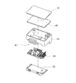
図3に、本実施形態の電動パワーステアリング装置の主要構成部品を分解した斜視図を示す。図示するように、本実施形態におけるコントロールユニット30は、制御回路基板40とパワー回路基板50とを含む構成となっている。例えば本実施形態では、ヒートシンク32にパワー基板50を取り付け、さらにモータ接続端子60と制御回路基板40を取り付け、これらにカバー31を被せた構造のコントロールユニット30としている(図3(A)等参照)。例えば本実施形態では、カバー31とヒートシンク32とでコントロールユニットケース(図10において符号35を付して示す)を形成している。
FIG. 3 is an exploded perspective view of main components of the electric power steering apparatus according to the present embodiment. As illustrated, con
制御回路基板40は、マイクロコンピュータ、コネクタ、リレー、ノイズ対策部品といった各種電子部品を搭載する基板である。図4に示す制御回路基板40においては、マイクロコンピュータなどの電子部品を搭載し終えた後に、パワー回路基板50との接続部に、スルーホールが存在するように電子部品が実装されている。例えば本実施形態の制御回路基板40は、コネクタ41、コイル42、電源リレー43、アルミ電解コンデンサ44等が基板に取り付けられた構成となっている(図4(B)参照)。
The
パワー回路基板50は、モータ駆動用の半導体スイッチング素子などを搭載する基板である。図5に示すパワー回路基板50においては、制御回路基板40と電気的に接続するための接続リード端子51がさらに実装されている。この接続リード端子51は、外力を受けた際の応力を緩和できる形状ないしは構造になっていれば、熱膨張などによって制御回路基板40とパワー回路基板50に相対的な位置変化が生じても接続部の信頼性を向上することができて好ましい。
The
なお、パワー回路基板50は、当該基板の下側の面をコントロールユニットケース35に設けた平面(例えば上述したヒートシンク32の面)に接触させて固定することにより、当該パワー回路基板50に発生する熱を放熱することができる(図3(A)等参照)。このようにパワー回路基板50をコントロールユニットケース35に固定する際は、放熱グリースや放熱シートをコントロールユニットケース35の平面とパワー回路基板50の間に入れることで、効率よく熱を伝達することができる。あるいは、ギアボックス3をヒートシンクとして利用する場合は、コントロールユニットケース35をギアボックス3に設けた平面と接触させて固定し放熱することが望ましい。この場合は、放熱グリースや放熱シートをコントロールユニットケース35の平面とギアボックス3の平面との間に入れることで、効率よく熱を伝達することができる。
The
ここで、制御回路基板40とパワー回路基板50との距離Aは、制御回路基板40に搭載され尚かつ当該電動パワーステアリング装置の外部に突出しない部品の中で最も背の高い部品(例えばコンデンサやコイルなどであり、図9では当該部品を符号45で示している)の当該高さB以下(A≦B)であることが好ましい(図9参照)。こうした場合には、当該コントロールユニット30ひいてはこれを搭載する装置の小型化を図りやすい。このため、車種毎にコントロールユニット30の搭載場所が変化するとしても当該コントロールユニット30の基板構成やケース形状、コネクタ位置などの変更を従来の場合よりも抑えることが可能である。
Here, the distance A between the
モータ20側の端子と電気的に接続されるモータ接続端子60は、例えば樹脂モールド等の絶縁部材で覆われている。このモータ接続端子60は、コントロールユニット30のいずれの辺にも配置できるように延長されていることが好ましい。モータ接続端子60が絶縁部材で覆われている電動パワーステアリング装置においては、当該モータ接続端子60をコントロールユニット30の内部で配線することにより、コントロールユニット外周の任意の場所でモータと接続することが可能になる(図10参照)。こうした場合には、車両の車種毎にコントロールユニットの搭載場所が変化しても、当該コントロールユニット30の基板構成やケース形状、コネクタ位置など、ユニット自体の構造そのものを変更せずに対応することが可能となる。また、モータ接続端子60は、基板に接続する位置とモータ端子に接続する位置がコントロールユニット30の異なる辺に存在する場合は、当該コントロールユニットケース35内で延長し配線されることがさらに好ましい(図10参照)。また、コントロールユニットケース35に、モータ接続端子60をガイドする部位が設けられていることも好ましい。例えばモータ接続端子60をコントロールユニットケース35内で延長して配線する場合、配線を引き回す際のガイドとして用いることができる。以上のように、モータ接続端子60をコントロールユニット30の内部で配線することとすれば、コントロールユニット外周の任意の場所で当該コントロールユニット30とモータ20とを接続することが可能となり、設計時のレイアウト自由度が向上する。
The
図6は、モータ接続端子60のバリエーション例を示す図である(図6(A)〜(D)参照)。図中の「モータ接続端子位置(1)」が示すのは、当該モータ接続端子60の制御回路基板40に対する接続部分60aの位置とモータ側の端子60bの位置とがコントロールユニット30の異なる辺(あるいは面)に存在する場合の例である。この場合のモータ接続用端子60は、制御回路基板40との接続位置を変えずに、モータ側の端子60bの位置までコントロールユニットケース35内部で延長される形状である(図6(A)、(B)参照)。一方、図中の「モータ接続端子位置(2)」が示すのは、当該モータ接続端子60の制御回路基板40に対する接続部分60aの位置とモータ側の端子60bの位置とがコントロールユニット30の同じ辺(あるいは面)に存在する場合の例である(図6(C)、(D)参照)。なお、図6(A)、(C)に示しているのはいわゆる端子台タイプのモータ接続端子60であり、図6(B)、(D)に示しているのはいわゆるバスバータイプのモータ接続端子60である。
FIG. 6 is a diagram showing a variation example of the motor connection terminal 60 (see FIGS. 6A to 6D). “Motor connection terminal position (1)” in the figure indicates that the position of the
図7は、コントロールユニット30の搭載場所のバリエーション例を示す図である(図7(A)〜(F)参照)。図7の1段目に示しているのは、近接配置構造であって、コントロールユニット30がモータ20に対して縦置きになり、モータ端の上に電源、信号コネクタが配置されるタイプである(図7(A)、(B)参照)。この場合、ギアボックス3またはモータ20にコントロールユニット30の固定部(コントロールユニット30が固定される箇所あるいは固定のための装置)を設ける。また、図7の2段目に示しているのは、近接配置構造であって、コントロールユニット30がモータ20に対して縦置きになり、モータ20の横に電源、信号コネクタが配置されるタイプである(図7(C)、(D)参照)。この場合、ギアボックス3またはモータ20にコントロールユニット30の固定部を設ける。図7の3段目に示しているのは、機電一体構造であって、ギアボックス3のウォーム収納部端に電源、信号コネクタが配置されるタイプである(図7(E)、(F)参照)。なお、上述したように図7はコントロールユニット30の搭載場所のバリエーション例を示しているにすぎず、他部品と干渉しない範囲で、ウォーム軸を中心にコントロールユニット30を回転させた配置が可能である。
FIG. 7 is a view showing a variation example of the mounting location of the control unit 30 (see FIGS. 7A to 7F). The first stage shown in FIG. 7 is a proximity arrangement structure in which the
また、モータ20、コントロールユニット30等の組付けは、図2の主要構成部品の製造工程に合わせて、組付け順のバリエーションを持たせることができる。これにより、主要構成部品の製造工程の自由度を向上させることが可能となる。組付け順のバリエーション例を説明すると以下のとおりである。すなわち、まずはモータ20をギアボックス3に組み付け、次にコントロールユニット30をギアボックス3に組み付けるというバリエーションがある(図7(A)〜(D)参照)。これとは逆に、まずコントロールユニット30をギアボックス3に組み付け、次にモータ20をギアボックス3に組み付けてもよい(図7(E)、(F)参照)。あるいは、モータ20にコントロールユニット30を組み付け、次にこのモータ20をギアボックス3に組み付けるようにしてもよい。
Further, the assembly of the
図8はコントロールユニットケース35のバリエーション例を示す図である。ここに示すコントロールユニットケース35は、ヒートシンク32とコントロールユニット固定部をアルミニウム製とし、当該ケースの側面とコネクタ類41’を樹脂で一体にしたものである。なお、図8においてはコネクタ類41’が一体化された樹脂ケースの側面部分を符号33で示している。
FIG. 8 is a view showing a variation example of the
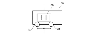
ここで、上述のようにモータ20とコントロールユニット30が近接して配置されている場合、モータ20側の端子と電気的に接続されるモータ接続端子60はその各端子間距離が等間隔で配置され、コントロールユニット30の固定部材(例えば固定用のボルト)34の位置の中心に合わせ左右対称に配置されていることが好ましい(図11参照)。このような電動パワーステアリング装置においては、コントロールユニット30をモータ20の近傍に配置した近接配置構造であっても、接続端子位置やコネクタ位置を変更したい場合や機電一体構造の配置にしようとした場合に大きな設計変更を回避することが可能である。例えば本実施形態では、コントロールユニット30の固定位置(より詳細には、当該コントロールユニット30に複数ある固定部材34間の中心位置)とモータ接続端子60の中心が揃って配置され左右対称になっており、接続端子形状を変えずに、コントロールユニット30の取付け方向を反転させることができる(図11等参照)。このような場合、例えばコントロールユニット30が端子を中心に180度回転したとしても端子部の形状の変更なしで取り付けが可能である(図7(C)、(D)等参照)。
Here, when the
次にコントロールユニット30の組立工程を説明する(図7等参照)。
Next, the assembly process of the
まず、コントロールユニットケース35に形成されている平面に放熱グリースを塗布した上で、パワー回路基板50をギアボックス3の所定位置へ固定する。そして、パワー回路基板50からのリードの位置決めのため、ギアボックス3に形成されている面にパワー回路基板50を突き当てて所定位置に設置し、ねじ留めなどにより固定する。次に、モータ接続端子部品をギアボックス3の所定位置へ、スナップフィット、ねじ等で固定する。次に、制御回路基板40のスルーホールヘ、モータ端子台部品やパワー回路基板50からのリード端子51が貫通するように設置し、コントロールユニットケース35にねじ留めなどにより固定する。次に、上記のリード端子51を半田付けにて接続することで電気的に接続する。次に、カバー31を取付けることでコントロールユニット30を構成する。
First, heat radiation grease is applied to a plane formed on the
続いて、コントロールユニット30とモータ20の組立工程を説明する。
Subsequently, an assembly process of the
コントロールユニット30とモータ20の組付けは、図7に示した搭載場所に応じて組み付けられる。なお、図7に例示した搭載場所は基本例であり、コントロールユニット30は、モータ軸を中心に回転させた範囲で搭載可能であり、さらに、コラムシャフト軸を中心に回転させた範囲で搭載可能である。このとき、コントロールユニット30は、コントロールユニット単体が脱着可能な方向から組み付けられる。また、コントロールユニット30とモータ20の接続部には、それぞれコントロールユニット30側とモータ20側から接続用の端子が設けられ、カバー31が取り付けられる。また、搭載場所に応じて、それぞれの端子(モータ接続端子60)は図6のような端子台タイプやバスバータイプに設定され、接続される。
The
以上、ここまで説明したように、本実施形態にかかる電動パワーステアリング装置は、回路基板の構成・配置等の変更を多彩な搭載場所に対応することが可能であるため、設計変更を最小限に留め、開発・設計工数を大幅に削減でき、短納期、およびコスト削減効果が得られる。具体的には、例えばコントロールユニット30の搭載位置を変更しても、制御回路基板40とパワー回路基板50及び相互の接続関係を変更せずに搭載することが可能であり、車両レイアウトに応じて適宜対応可能であるから汎用性が高い。また、コントロールユニットケース35の形状およびモータ接続端子60を適宜変更することで、モータ20と近接した近接配置構造、あるいはギアボックス3に直接結合した機電一体構造とすることもできる。
As described above, since the electric power steering device according to the present embodiment can cope with various mounting locations for changes in the configuration and arrangement of the circuit board, the design change can be minimized. The development and design man-hours can be greatly reduced, resulting in quick delivery and cost reduction effects. Specifically, for example, even if the mounting position of the
さらに、本実施形態の電動パワーステアリング装置において、コンデンサ、コイル等の大型の部品は、基板の構成と配置を変更せずに、モータ出力やその他要件に応じて変更可能である。別の表現をすれば、本実施形態では、モータ電流の大小や車両レイアウト制約により設計変更が必要となる箇所をモジュール部品に限定し、基板を共通仕様(プラットフォーム化)することで開発や評価の工数を削減できるようにしている。 Furthermore, in the electric power steering apparatus of the present embodiment, large components such as capacitors and coils can be changed according to the motor output and other requirements without changing the configuration and arrangement of the substrate. In other words, in this embodiment, the parts that require design changes due to the motor current size and vehicle layout constraints are limited to module parts, and development and evaluation can be performed by making the board a common specification (platforming). The man-hour can be reduced.
なお、上述の実施形態は本発明の好適な実施の一例ではあるがこれに限定されるものではなく本発明の要旨を逸脱しない範囲において種々変形実施可能である。例えば上述した実施形態において、制御回路基板40とパワー回路基板50の電気的接続をすべて制御回路基板40を経由して半田付けで行う構造とすれば、部品間の半田付けを1つの面のみで行うことが可能となる。こうした場合には組立工程をさらに簡素化することが可能である。
The above-described embodiment is an example of a preferred embodiment of the present invention, but is not limited thereto, and various modifications can be made without departing from the scope of the present invention. For example, in the above-described embodiment, if all the electrical connections between the
3…ギアボックス、20…モータ、30…コントロールユニット、34…固定用ボルト(固定部材)、35…コントロールユニットケース(ケース)、40…制御回路基板、45…制御回路基板に搭載され尚かつ当該電動パワーステアリング装置の外部に突出しない部品の中で最も背の高い部品、50…パワー回路基板、60…モータ接続端子
DESCRIPTION OF
Claims (4)
前記コントロールユニットは、各種電子部品を搭載する制御回路基板と、モータ駆動用の半導体スイッチング素子などを搭載するパワー回路基板とにより2層に構成され、
前記制御回路基板は、パワー回路基板よりも大きく、
前記モータ側の端子と電気的に接続されるモータ接続端子が絶縁部材で覆われ、前記コントロールユニットのいずれの辺にも配置できるように延長されており、
前記モータ接続端子は、基板に接続する位置と前記モータ端子に接続する位置が前記コントロールユニットの異なる辺に存在する場合は、ケース内で延長し配線されることを特徴とする電動パワーステアリング装置。 In an electric power steering apparatus including a motor capable of applying steering assist torque and a control unit for driving the motor,
The control unit is configured in two layers by a control circuit board on which various electronic components are mounted and a power circuit board on which a semiconductor switching element for driving a motor is mounted
It said control circuit board is much larger than the power circuit board,
The motor connection terminal that is electrically connected to the terminal on the motor side is covered with an insulating member, and extended so that it can be placed on any side of the control unit,
The electric power steering apparatus according to claim 1, wherein the motor connection terminal is extended and wired in a case when the position connected to the substrate and the position connected to the motor terminal are on different sides of the control unit .
The distance A between the control circuit board and the power circuit board is equal to or less than the height B of the tallest part mounted on the control circuit board and not projecting outside the electric power steering device. The electric power steering apparatus according to claim 1.
Priority Applications (1)
| Application Number | Priority Date | Filing Date | Title |
|---|---|---|---|
| JP2008132390A JP5229612B2 (en) | 2008-05-20 | 2008-05-20 | Electric power steering device |
Applications Claiming Priority (1)
| Application Number | Priority Date | Filing Date | Title |
|---|---|---|---|
| JP2008132390A JP5229612B2 (en) | 2008-05-20 | 2008-05-20 | Electric power steering device |
Publications (3)
| Publication Number | Publication Date |
|---|---|
| JP2009280018A JP2009280018A (en) | 2009-12-03 |
| JP2009280018A5 JP2009280018A5 (en) | 2011-03-31 |
| JP5229612B2 true JP5229612B2 (en) | 2013-07-03 |
Family
ID=41450960
Family Applications (1)
| Application Number | Title | Priority Date | Filing Date |
|---|---|---|---|
| JP2008132390A Active JP5229612B2 (en) | 2008-05-20 | 2008-05-20 | Electric power steering device |
Country Status (1)
| Country | Link |
|---|---|
| JP (1) | JP5229612B2 (en) |
Families Citing this family (4)
| Publication number | Priority date | Publication date | Assignee | Title |
|---|---|---|---|---|
| JP2010173465A (en) * | 2009-01-29 | 2010-08-12 | Nsk Ltd | Electric power steering device |
| WO2012073412A1 (en) * | 2010-12-02 | 2012-06-07 | 日本精工株式会社 | Electric power steering device |
| EP2574521B1 (en) * | 2010-12-07 | 2016-11-16 | NSK Ltd. | Electric power steering device |
| CN106458249B (en) * | 2014-06-27 | 2019-01-18 | 三菱电机株式会社 | Integrated electric servo steering device and its manufacturing method |
Family Cites Families (6)
| Publication number | Priority date | Publication date | Assignee | Title |
|---|---|---|---|---|
| JP4618474B2 (en) * | 2001-04-16 | 2011-01-26 | 株式会社ジェイテクト | Electric power steering device |
| JP3951210B2 (en) * | 2001-07-04 | 2007-08-01 | オムロン株式会社 | control unit |
| JP2003332526A (en) * | 2001-11-07 | 2003-11-21 | Hitachi Ltd | Power conversion apparatus |
| JP4110867B2 (en) * | 2002-07-23 | 2008-07-02 | 日本精工株式会社 | ECU of electric power steering device |
| JP4046005B2 (en) * | 2003-05-12 | 2008-02-13 | 株式会社デンソー | Electric motor drive device and electric power steering device |
| JP2007186145A (en) * | 2006-01-16 | 2007-07-26 | Nsk Ltd | Electric power steering device |
-
2008
- 2008-05-20 JP JP2008132390A patent/JP5229612B2/en active Active
Also Published As
| Publication number | Publication date |
|---|---|
| JP2009280018A (en) | 2009-12-03 |
Similar Documents
| Publication | Publication Date | Title |
|---|---|---|
| JP5067159B2 (en) | Electric power steering device | |
| US8102138B2 (en) | Electric power steering apparatus and method of assembling the same | |
| JP6396228B2 (en) | Electric drive device and electric power steering device | |
| JP4909961B2 (en) | Control device for electric power steering | |
| JP6408926B2 (en) | Electric drive device and electric power steering device | |
| US20090183940A1 (en) | Electric Power Steering Apparatus | |
| US11362569B2 (en) | Electric drive apparatus, and electric power steering apparatus | |
| WO2015119224A1 (en) | On-board electronic control unit and on-board electromechanical integrated electric motor | |
| EP2982570B1 (en) | Motor control device and production method therefor | |
| JP4661508B2 (en) | Electric power steering device | |
| JP6863875B2 (en) | Electric drive device and electric power steering device | |
| WO2021033678A1 (en) | Electric powered drive device, and method for assembling electric powered drive device | |
| JP6522358B2 (en) | Electric drive device and electric power steering device | |
| JP5298459B2 (en) | Electric power steering device | |
| JP5229612B2 (en) | Electric power steering device | |
| JP2009078690A (en) | Electrical power steering device | |
| JP7102548B2 (en) | Electronic control device and electric power steering device | |
| JP5787000B2 (en) | Electric power steering device | |
| JP5967425B2 (en) | Electric power steering device | |
| JP5702046B2 (en) | Electric power steering device | |
| JP5804869B2 (en) | Control unit for electric power steering system | |
| JP6416647B2 (en) | Electric drive device and electric power steering device | |
| JP2009012631A (en) | Electric power steering device | |
| JP2008179248A (en) | Electric power steering device | |
| JP2012153243A (en) | Electric power steering controller |
Legal Events
| Date | Code | Title | Description |
|---|---|---|---|
| A521 | Written amendment |
Free format text: JAPANESE INTERMEDIATE CODE: A523 Effective date: 20110210 |
|
| A621 | Written request for application examination |
Free format text: JAPANESE INTERMEDIATE CODE: A621 Effective date: 20110210 |
|
| A977 | Report on retrieval |
Free format text: JAPANESE INTERMEDIATE CODE: A971007 Effective date: 20120913 |
|
| A131 | Notification of reasons for refusal |
Free format text: JAPANESE INTERMEDIATE CODE: A131 Effective date: 20121114 |
|
| A521 | Written amendment |
Free format text: JAPANESE INTERMEDIATE CODE: A523 Effective date: 20121225 |
|
| TRDD | Decision of grant or rejection written | ||
| A01 | Written decision to grant a patent or to grant a registration (utility model) |
Free format text: JAPANESE INTERMEDIATE CODE: A01 Effective date: 20130222 |
|
| A61 | First payment of annual fees (during grant procedure) |
Free format text: JAPANESE INTERMEDIATE CODE: A61 Effective date: 20130307 |
|
| FPAY | Renewal fee payment (event date is renewal date of database) |
Free format text: PAYMENT UNTIL: 20160329 Year of fee payment: 3 |
|
| R150 | Certificate of patent or registration of utility model |
Ref document number: 5229612 Country of ref document: JP Free format text: JAPANESE INTERMEDIATE CODE: R150 Free format text: JAPANESE INTERMEDIATE CODE: R150 |