JP5227344B2 - Implant, mandrel, and implant formation method - Google Patents
Implant, mandrel, and implant formation method Download PDFInfo
- Publication number
- JP5227344B2 JP5227344B2 JP2009553681A JP2009553681A JP5227344B2 JP 5227344 B2 JP5227344 B2 JP 5227344B2 JP 2009553681 A JP2009553681 A JP 2009553681A JP 2009553681 A JP2009553681 A JP 2009553681A JP 5227344 B2 JP5227344 B2 JP 5227344B2
- Authority
- JP
- Japan
- Prior art keywords
- coil
- mandrel
- implant
- shape
- winding
- Prior art date
- Legal status (The legal status is an assumption and is not a legal conclusion. Google has not performed a legal analysis and makes no representation as to the accuracy of the status listed.)
- Active
Links
- 239000007943 implant Substances 0.000 title claims description 68
- 238000000034 method Methods 0.000 title claims description 38
- -1 mandrel Substances 0.000 title description 2
- 230000015572 biosynthetic process Effects 0.000 title 1
- 238000004804 winding Methods 0.000 claims description 64
- 239000003550 marker Substances 0.000 claims description 37
- 230000002792 vascular Effects 0.000 claims description 27
- 229910052751 metal Inorganic materials 0.000 claims description 16
- 239000002184 metal Substances 0.000 claims description 16
- 150000002739 metals Chemical class 0.000 claims description 7
- KDLHZDBZIXYQEI-UHFFFAOYSA-N Palladium Chemical compound [Pd] KDLHZDBZIXYQEI-UHFFFAOYSA-N 0.000 claims description 6
- 238000010438 heat treatment Methods 0.000 claims description 6
- BASFCYQUMIYNBI-UHFFFAOYSA-N platinum Chemical group [Pt] BASFCYQUMIYNBI-UHFFFAOYSA-N 0.000 claims description 6
- 239000000956 alloy Substances 0.000 claims description 4
- 229910045601 alloy Inorganic materials 0.000 claims description 4
- 229910001260 Pt alloy Inorganic materials 0.000 claims description 3
- BQCADISMDOOEFD-UHFFFAOYSA-N Silver Chemical compound [Ag] BQCADISMDOOEFD-UHFFFAOYSA-N 0.000 claims description 3
- PCHJSUWPFVWCPO-UHFFFAOYSA-N gold Chemical compound [Au] PCHJSUWPFVWCPO-UHFFFAOYSA-N 0.000 claims description 3
- 229910052737 gold Inorganic materials 0.000 claims description 3
- 239000010931 gold Substances 0.000 claims description 3
- 229910052741 iridium Inorganic materials 0.000 claims description 3
- GKOZUEZYRPOHIO-UHFFFAOYSA-N iridium atom Chemical compound [Ir] GKOZUEZYRPOHIO-UHFFFAOYSA-N 0.000 claims description 3
- 229910052763 palladium Inorganic materials 0.000 claims description 3
- 229910052697 platinum Inorganic materials 0.000 claims description 3
- 229910052702 rhenium Inorganic materials 0.000 claims description 3
- WUAPFZMCVAUBPE-UHFFFAOYSA-N rhenium atom Chemical compound [Re] WUAPFZMCVAUBPE-UHFFFAOYSA-N 0.000 claims description 3
- 229910052703 rhodium Inorganic materials 0.000 claims description 3
- 239000010948 rhodium Substances 0.000 claims description 3
- MHOVAHRLVXNVSD-UHFFFAOYSA-N rhodium atom Chemical compound [Rh] MHOVAHRLVXNVSD-UHFFFAOYSA-N 0.000 claims description 3
- 229910052709 silver Inorganic materials 0.000 claims description 3
- 239000004332 silver Substances 0.000 claims description 3
- 229910052715 tantalum Inorganic materials 0.000 claims description 3
- GUVRBAGPIYLISA-UHFFFAOYSA-N tantalum atom Chemical compound [Ta] GUVRBAGPIYLISA-UHFFFAOYSA-N 0.000 claims description 3
- WFKWXMTUELFFGS-UHFFFAOYSA-N tungsten Chemical compound [W] WFKWXMTUELFFGS-UHFFFAOYSA-N 0.000 claims description 3
- 229910052721 tungsten Inorganic materials 0.000 claims description 3
- 239000010937 tungsten Substances 0.000 claims description 3
- 239000000463 material Substances 0.000 description 8
- 239000007858 starting material Substances 0.000 description 8
- 206010002329 Aneurysm Diseases 0.000 description 6
- 210000004204 blood vessel Anatomy 0.000 description 5
- 238000012986 modification Methods 0.000 description 5
- 230000004048 modification Effects 0.000 description 5
- 238000010586 diagram Methods 0.000 description 4
- 210000005166 vasculature Anatomy 0.000 description 4
- 230000006870 function Effects 0.000 description 3
- 238000001727 in vivo Methods 0.000 description 3
- 238000013459 approach Methods 0.000 description 2
- 230000010102 embolization Effects 0.000 description 2
- 238000003384 imaging method Methods 0.000 description 2
- 230000002093 peripheral effect Effects 0.000 description 2
- 238000012545 processing Methods 0.000 description 2
- 238000012360 testing method Methods 0.000 description 2
- 201000008450 Intracranial aneurysm Diseases 0.000 description 1
- 229910000831 Steel Inorganic materials 0.000 description 1
- 230000002411 adverse Effects 0.000 description 1
- 230000003466 anti-cipated effect Effects 0.000 description 1
- 210000004556 brain Anatomy 0.000 description 1
- 210000001715 carotid artery Anatomy 0.000 description 1
- 238000002716 delivery method Methods 0.000 description 1
- 230000003073 embolic effect Effects 0.000 description 1
- 239000012530 fluid Substances 0.000 description 1
- 238000002594 fluoroscopy Methods 0.000 description 1
- 210000004013 groin Anatomy 0.000 description 1
- 238000009998 heat setting Methods 0.000 description 1
- 238000005304 joining Methods 0.000 description 1
- 238000004519 manufacturing process Methods 0.000 description 1
- HLXZNVUGXRDIFK-UHFFFAOYSA-N nickel titanium Chemical compound [Ti].[Ti].[Ti].[Ti].[Ti].[Ti].[Ti].[Ti].[Ti].[Ti].[Ti].[Ni].[Ni].[Ni].[Ni].[Ni].[Ni].[Ni].[Ni].[Ni].[Ni].[Ni].[Ni].[Ni].[Ni] HLXZNVUGXRDIFK-UHFFFAOYSA-N 0.000 description 1
- 229910001000 nickel titanium Inorganic materials 0.000 description 1
- 229910000510 noble metal Inorganic materials 0.000 description 1
- 230000005855 radiation Effects 0.000 description 1
- 239000010959 steel Substances 0.000 description 1
- 238000003860 storage Methods 0.000 description 1
- 239000000126 substance Substances 0.000 description 1
Images


Classifications
-
- A—HUMAN NECESSITIES
- A61—MEDICAL OR VETERINARY SCIENCE; HYGIENE
- A61B—DIAGNOSIS; SURGERY; IDENTIFICATION
- A61B17/00—Surgical instruments, devices or methods, e.g. tourniquets
- A61B17/12—Surgical instruments, devices or methods, e.g. tourniquets for ligaturing or otherwise compressing tubular parts of the body, e.g. blood vessels, umbilical cord
- A61B17/12022—Occluding by internal devices, e.g. balloons or releasable wires
- A61B17/12099—Occluding by internal devices, e.g. balloons or releasable wires characterised by the location of the occluder
- A61B17/12109—Occluding by internal devices, e.g. balloons or releasable wires characterised by the location of the occluder in a blood vessel
- A61B17/12113—Occluding by internal devices, e.g. balloons or releasable wires characterised by the location of the occluder in a blood vessel within an aneurysm
-
- A—HUMAN NECESSITIES
- A61—MEDICAL OR VETERINARY SCIENCE; HYGIENE
- A61B—DIAGNOSIS; SURGERY; IDENTIFICATION
- A61B17/00—Surgical instruments, devices or methods, e.g. tourniquets
- A61B17/12—Surgical instruments, devices or methods, e.g. tourniquets for ligaturing or otherwise compressing tubular parts of the body, e.g. blood vessels, umbilical cord
- A61B17/12022—Occluding by internal devices, e.g. balloons or releasable wires
- A61B17/12131—Occluding by internal devices, e.g. balloons or releasable wires characterised by the type of occluding device
- A61B17/1214—Coils or wires
- A61B17/12145—Coils or wires having a pre-set deployed three-dimensional shape
-
- A—HUMAN NECESSITIES
- A61—MEDICAL OR VETERINARY SCIENCE; HYGIENE
- A61B—DIAGNOSIS; SURGERY; IDENTIFICATION
- A61B17/00—Surgical instruments, devices or methods, e.g. tourniquets
- A61B17/12—Surgical instruments, devices or methods, e.g. tourniquets for ligaturing or otherwise compressing tubular parts of the body, e.g. blood vessels, umbilical cord
- A61B17/12022—Occluding by internal devices, e.g. balloons or releasable wires
- A61B17/12131—Occluding by internal devices, e.g. balloons or releasable wires characterised by the type of occluding device
- A61B17/1214—Coils or wires
- A61B17/12154—Coils or wires having stretch limiting means
-
- A—HUMAN NECESSITIES
- A61—MEDICAL OR VETERINARY SCIENCE; HYGIENE
- A61F—FILTERS IMPLANTABLE INTO BLOOD VESSELS; PROSTHESES; DEVICES PROVIDING PATENCY TO, OR PREVENTING COLLAPSING OF, TUBULAR STRUCTURES OF THE BODY, e.g. STENTS; ORTHOPAEDIC, NURSING OR CONTRACEPTIVE DEVICES; FOMENTATION; TREATMENT OR PROTECTION OF EYES OR EARS; BANDAGES, DRESSINGS OR ABSORBENT PADS; FIRST-AID KITS
- A61F2/00—Filters implantable into blood vessels; Prostheses, i.e. artificial substitutes or replacements for parts of the body; Appliances for connecting them with the body; Devices providing patency to, or preventing collapsing of, tubular structures of the body, e.g. stents
- A61F2/02—Prostheses implantable into the body
- A61F2/04—Hollow or tubular parts of organs, e.g. bladders, tracheae, bronchi or bile ducts
- A61F2/06—Blood vessels
- A61F2/07—Stent-grafts
-
- A—HUMAN NECESSITIES
- A61—MEDICAL OR VETERINARY SCIENCE; HYGIENE
- A61L—METHODS OR APPARATUS FOR STERILISING MATERIALS OR OBJECTS IN GENERAL; DISINFECTION, STERILISATION OR DEODORISATION OF AIR; CHEMICAL ASPECTS OF BANDAGES, DRESSINGS, ABSORBENT PADS OR SURGICAL ARTICLES; MATERIALS FOR BANDAGES, DRESSINGS, ABSORBENT PADS OR SURGICAL ARTICLES
- A61L27/00—Materials for grafts or prostheses or for coating grafts or prostheses
- A61L27/02—Inorganic materials
- A61L27/04—Metals or alloys
-
- A—HUMAN NECESSITIES
- A61—MEDICAL OR VETERINARY SCIENCE; HYGIENE
- A61B—DIAGNOSIS; SURGERY; IDENTIFICATION
- A61B17/00—Surgical instruments, devices or methods, e.g. tourniquets
- A61B2017/00526—Methods of manufacturing
-
- A—HUMAN NECESSITIES
- A61—MEDICAL OR VETERINARY SCIENCE; HYGIENE
- A61B—DIAGNOSIS; SURGERY; IDENTIFICATION
- A61B17/00—Surgical instruments, devices or methods, e.g. tourniquets
- A61B2017/00831—Material properties
- A61B2017/00862—Material properties elastic or resilient
-
- A—HUMAN NECESSITIES
- A61—MEDICAL OR VETERINARY SCIENCE; HYGIENE
- A61B—DIAGNOSIS; SURGERY; IDENTIFICATION
- A61B17/00—Surgical instruments, devices or methods, e.g. tourniquets
- A61B2017/00831—Material properties
- A61B2017/00867—Material properties shape memory effect
Landscapes
- Health & Medical Sciences (AREA)
- Life Sciences & Earth Sciences (AREA)
- Surgery (AREA)
- Public Health (AREA)
- Veterinary Medicine (AREA)
- Animal Behavior & Ethology (AREA)
- General Health & Medical Sciences (AREA)
- Heart & Thoracic Surgery (AREA)
- Biomedical Technology (AREA)
- Engineering & Computer Science (AREA)
- Vascular Medicine (AREA)
- Molecular Biology (AREA)
- Nuclear Medicine, Radiotherapy & Molecular Imaging (AREA)
- Reproductive Health (AREA)
- Medical Informatics (AREA)
- Oral & Maxillofacial Surgery (AREA)
- Transplantation (AREA)
- Neurosurgery (AREA)
- Chemical & Material Sciences (AREA)
- Gastroenterology & Hepatology (AREA)
- Pulmonology (AREA)
- Cardiology (AREA)
- Epidemiology (AREA)
- Medicinal Chemistry (AREA)
- Dermatology (AREA)
- Inorganic Chemistry (AREA)
- Surgical Instruments (AREA)
- Prostheses (AREA)
Description
本出願は、2007年3月13日に提出された出願番号第60/894,589号の仮出願、両方とも2007年3月14日に提出された出願番号第60/894,865号の仮出願および出願番号第60/894,858号の仮出願の米国特許法第119条(e)の下での利益を主張するものであり、これらの仮出願はすべて、参照によってその全体がこの明細書の中に引用されている。
This application is a provisional application of
本発明は、移植可能なコイルの形成方法、このような方法によって形成されたコイル、コイルインプラントの形状を形成するために使用されるマンドレル、コイルインプラント形成方法、および、このような方法によってあるいはこのようなマンドレルで形成されたコイルインプラントに関するものである。 The present invention relates to a method of forming an implantable coil, a coil formed by such a method, a mandrel used to form the shape of a coil implant, a method of forming a coil implant, and a method such as this or The present invention relates to a coil implant formed of such a mandrel.
インプラントは、マイクロカテーテルによって動脈瘤のような患者の血管部位へ送出されて、その血管部位を閉塞しあるいは塞栓する。典型的な例では、このインプラントは、送出用マイクロカテーテルあるいはこのマイクロカテーテルの内部に収容された案内ワイヤのいずれか一方の遠位端に係合され、かつ、そこから、治療すべき血管部位の中へ調整可能に解除されるものである。このインプラントを送出する臨床医は、血管系を通してマイクロカテーテルあるいは案内用カテーテルを誘導しなければならず、また、頭蓋内動脈瘤の場合には、そのマイクロカテーテルの誘導は曲がりくねった微小血管系を通して行われる。この送出は、蛍光透視法あるいは別の適切な手段によって視覚化することができる。上記のカテーテルあるいは案内用ワイヤの遠位端が所望の血管部位にいったん置かれると、臨床医は次いで、インプラントがその部位を充分に塞栓するように位置決めされることを保証するために、インプラントをその血管部位で関節状に連結し始めなければならない。インプラントが適切にいったん位置決めされると、臨床医はその後、インプラントの上記位置決めを歪めることなく、インプラントを上記のカテーテルあるいは案内用ワイヤから取り外さなければならない。取り外しは、電気分解的取り外し、化学的取り外し、機械的取り外し、油圧式取り外し、および熱的取り外しが含まれる、さまざまな手段によって行うことができる。 The implant is delivered by a microcatheter to the patient's vascular site, such as an aneurysm, to occlude or embolize the vascular site. In a typical example, the implant is engaged to the distal end of either the delivery microcatheter or the guide wire housed within the microcatheter and from there the vascular site to be treated. It is released in an adjustable manner. The clinician delivering the implant must guide the microcatheter or guiding catheter through the vasculature, and in the case of an intracranial aneurysm, the microcatheter is guided through the tortuous microvasculature. Is called. This delivery can be visualized by fluoroscopy or another suitable means. Once the distal end of the catheter or guide wire has been placed at the desired vascular site, the clinician then uses the implant to ensure that the implant is positioned to fully embolize the site. It must begin to articulate at the vascular site. Once the implant is properly positioned, the clinician must then remove the implant from the catheter or guide wire without distorting the positioning of the implant. Removal can be done by a variety of means, including electrolytic removal, chemical removal, mechanical removal, hydraulic removal, and thermal removal.
従来は、カテーテルあるいは案内用ワイヤからの取り外しによって直線状ワイヤから形成される三次元コイルが提供されていた。この三次元コイルは典型的には、取り外し(例えば生体内での)の際に、直線状ワイヤから、理想的な環境では塞栓すべき血管部位の形状に適合するであろう二次的構造(すなわち、拡張したあるいはらせん状のコイル構造)を有しているコイルの形状あるいは構造へ再構成される金属から、形成されている。しかしながら、生体内で形成された従来技術のコイルは、上記血管部位に適合する形状をもたらすことが決まってできなかったため、上記血管部位の塞栓が効果的でないという結果になる。従来技術の三次元コイルが初めに上記血管部位に適合するときであっても、結果として生じるコイルの二次的構造は、上記血管部位とのそれらの適合を維持するために充分に安定しているとはいえない。例えば、生体内で形成された三次元状球形コイルは、上記血管部位の構造とは異なった二次的構造になるために、それら自体へ折り畳まれる傾向にある。同様に、生体内で形成された三次元状立方体コイルは、それらの立方体形状を保持することなく、「積み重ね硬貨」と同様に、多くの場合、それら自体の上に崩れる。 Conventionally, a three-dimensional coil formed from a straight wire by removal from a catheter or guide wire has been provided. This three-dimensional coil is typically removed from a straight wire during removal (eg, in vivo) from a secondary structure that will conform to the shape of the vessel site to be embolized in an ideal environment ( That is, it is formed from a metal reconstructed into a coil shape or structure having an expanded or helical coil structure. However, prior art coils formed in vivo have not been able to provide a shape that fits the vascular site, resulting in ineffective embolization of the vascular site. Even when prior art three-dimensional coils initially conform to the vascular site, the resulting secondary structure of the coil is sufficiently stable to maintain their conformity with the vascular site. I can't say. For example, three-dimensional spherical coils formed in a living body tend to be folded into themselves because they have a secondary structure different from the structure of the blood vessel site. Similarly, three-dimensional cube coils formed in vivo are often collapsed on themselves, like “stacked coins”, without retaining their cube shape.
上記のことを考慮に入れると、塞栓すべき血管部位へ実質的に適合するコイルインプラントについての要望が存在している。 In view of the above, there is a need for a coil implant that substantially conforms to the vascular site to be embolized.
発明の概要
本発明は、1つの実施形態では、動脈瘤のような血管部位への詰め込みを最適化するように設計された三次元コイルを備えるインプラントに関するものである。本発明のインプラントは、その二次的形状のために、血管部位へ実質的に適合することができ、それによっていっそう効果的な塞栓形成をもたらす、ということが予想される。特に、本発明の三次元コイルの形状は、1つ以上の閉じられていないメビウスループで構成されている。
SUMMARY OF THE INVENTION The present invention, in one embodiment, relates to an implant comprising a three-dimensional coil designed to optimize stuffing into a vascular site such as an aneurysm. It is expected that the implant of the present invention will be able to substantially conform to the vascular site due to its secondary shape, thereby resulting in more effective embolization. In particular, the shape of the three-dimensional coil of the present invention is composed of one or more unclosed Mobius loops.
1つの実施形態では、本発明によって、1つ以上の閉じられていないメビウスループを備える三次元血管内コイルを提供する。このコイルは、カテーテルあるいは案内用ワイヤから解放されたときにマンドレルの周りにおける巻き付けパターンに対応するパターンを形成するために、偏倚(バイアス)されている。この偏倚によって、上記コイルは球体の外面に適合する三次元形状に置かれる。上記巻き付けパターンには、その形状を覆うように配置された、少なくとも1つの閉じられていないメビウスループがある。他の実施形態では、上記巻き付けパターンには、その形状を覆うように配置された、少なくとも2つあるいは3つの閉じられていないメビウスループがある。 In one embodiment, the present invention provides a three-dimensional endovascular coil comprising one or more unclosed Mobius loops. The coil is biased to form a pattern corresponding to the winding pattern around the mandrel when released from the catheter or guide wire. This bias places the coil in a three-dimensional shape that conforms to the outer surface of the sphere. The winding pattern has at least one unclosed Mobius loop arranged to cover its shape. In another embodiment, the wrapping pattern has at least two or three unclosed Mobius loops arranged to cover the shape.
このコイルの形状は、球体の表面を覆うように配置された8つの実質的三角形のパターンに適合することもできる。1つの実施形態では、この8つの実質的三角形には、それぞれの三角形の中心から外方へ(凸状に)離れるように湾曲している側面がある4つの実質的三角形と、それぞれの三角形の中心へ向かって内方へ(凹状に)湾曲している側面がある4つの実質的三角形とが含まれている。このコイルの形状には、実質的三角形どうしの間の通路に、球体の中心の周りに湾曲しているとともに上記三角形に対応する少なくとも4つの点の周りでも湾曲している通路に、または、双曲放物面の輪郭あるいは鞍の輪郭に概ね従うように説明することのできる通路に適合するループがあってもよい。このコイルの長さに左右されるが、少なくとも1回の、また、好ましくは複数回のコイルの巻き付けが、上記巻き付けパターンに従って上記マンドレルの周りで行われるであろう。 The shape of this coil can also be adapted to an eight substantially triangular pattern arranged to cover the surface of the sphere. In one embodiment, the eight substantial triangles have four substantial triangles with sides that are curved outward (convex) away from the center of each triangle, and Included are four substantial triangles with sides that curve inward (concave) toward the center. The shape of the coil includes a path between substantially triangles, a path curved around the center of the sphere and also curved around at least four points corresponding to the triangle, or There may be loops that fit the passages that can be described to generally follow the contour of a paraboloid or ridge. Depending on the length of the coil, at least one and preferably multiple windings of the coil will take place around the mandrel according to the winding pattern.
本発明の1つの実施形態では、患者の血管部位を塞栓する方法であって、上記インプラントを上記血管部位へ送出するステップを備えてなる方法が与えられている。このインプラントは送出装置で送出される。この送出装置は、必要に応じて案内用ワイヤおよび/またはポジショナーが含まれているマイクロカテーテルであってもよい。 In one embodiment of the invention, there is provided a method of embolizing a patient's vascular site comprising delivering the implant to the vascular site. The implant is delivered with a delivery device. The delivery device may be a microcatheter that includes a guide wire and / or positioner as required.
本発明の別の実施形態はマンドレルに関するものである。このマンドレルには、球体と、この球体の外側表面に配置された4つのマーカーのような複数のマーカーとが含まれている。必要に応じて、これらのマーカーのうちの1つには軸部が含まれている。これら4つのマーカーのそれぞれは、隣接するマーカーどうしの間の通路を画定しており、また、この通路は、上記球体の外側表面の周りに巻き付けられるコイルのための巻き付けパターンを画定しているのが好ましい。この巻き付けパターンには、あるマーカーに上記通路が隣接して配置されている箇所に対応する上記球体の上記表面に十字状に交差する一組の連続的折り返しもまた含まれている。 Another embodiment of the invention relates to a mandrel. The mandrel includes a sphere and a plurality of markers such as four markers arranged on the outer surface of the sphere. If desired, one of these markers includes a shank. Each of these four markers defines a passage between adjacent markers, and this passage defines a winding pattern for a coil wound around the outer surface of the sphere. Is preferred. The winding pattern also includes a set of continuous folds that cross the surface of the sphere corresponding to where the passage is located adjacent to a marker.
本発明の別の実施形態では、本発明のインプラントの形成方法が与えられている。上記コイルの形成方法は、そのコイルを上記巻き付けパターンによって上記マンドレルに巻き付けるプロセスを含む。この方法は、上記マンドレルと巻き付けられたコイルとを加熱するステップをさらに含む。この方法は、巻き付けられたコイルから仕上げコイルを形成する付加的処理用ステップもまた含む。
例えば、本発明は以下の項目を提供する。
(項目1)
1つ以上の閉じられていないメビウスループを備えている三次元血管内コイル。
(項目2)
巻き付けパターンに適合するように偏倚されたコイル長さを有しているコイルを備えてなり、前記巻き付けパターンは、球体の外側表面の形状にほぼ適合しており、前記巻き付けパターンには、その形状を覆うように配置された、少なくとも1つの閉じられていないメビウスループがあるインプラント。
(項目3)
前記巻き付けパターンには、その形状を覆うように配置された、複数の閉じられていないメビウスループがある項目2に記載のインプラント。
(項目4)
前記巻き付けパターンは、前記形状を覆うように配置された8つの実質的三角形部分をさらに備えている項目2に記載のインプラント。
(項目5)
前記三角形には中心があり、かつ、4つの三角形には、前記中心から外方へ離れるように湾曲している側面がある項目4に記載のインプラント。
(項目6)
前記三角形には中心があり、かつ、4つの三角形には、前記中心へ向かって内方へ湾曲している側面がある項目4に記載のインプラント。
(項目7)
前記巻き付けパターンは、少なくとも第1型曲線および第2型曲線を有している少なくとも1つのループをさらに備え、前記第1型曲線は、球体の形状に対応しており、前記第2型曲線は、少なくとも1つのループの通路に沿って配置された8つの実質的三角形部分に対応する複数の曲線を備えている項目2に記載のインプラント。
(項目8)
前記コイルは、血管部位へ実質的に適合している項目1または2に記載のインプラント。
(項目9)
前記コイルは、金属ワイヤからなっている項目1または2に記載のインプラント。
(項目10)
前記ワイヤは、白金、パラジウム、ロジウム、レニウム、イリジウム、金、銀、タングステン、タンタル、これらの金属の2つ以上からなる合金、あるいは超弾性金属から構成される群から選択された金属からなっている項目9に記載のインプラント。
(項目11)
前記ワイヤは、白金合金である項目10に記載のインプラント。
(項目12)
項目1または2のインプラントを送出装置によって血管部位へ送出し、それによって、前記血管部位を塞栓する患者の血管部位の塞栓方法。
(項目13)
前記インプラントは、前記血管部位へ実質的に適合する項目12に記載の方法。
(項目14)
付加的なインプラントを前記血管部位へ送出するステップを備えている項目13に記載の方法。
(項目15)
表面に配置された4つのマーカーを有している球体であって、それぞれのマーカーが前記球体の前記表面に当接する円筒によって画定されている球体を備え、
前記マーカーどうしの間における前記球体の前記表面は、前記球体の前記表面に十字状に交差する巻き付けパターンと、隣接する前記マーカーどうしの間における前記球体の前記表面に前記巻き付けパターンの複数の交差点を画定する複数の中間点とを画定しているマンドレル。
(項目16)
前記4つのマーカーのうちの1つから延出している軸部をさらに備えている項目15に記載のマンドレル。
(項目17)
このマンドレルは、約0.5〜約0.75の、球体直径に対するマーカー直径の比を有している項目16に記載のマンドレル。
(項目18)
前記の比は、約0.55〜約0.7である項目17に記載のマンドレル。
(項目19)
前記の比は、約0.61〜約0.65である項目18に記載のマンドレル。
(項目20)
前記マーカーは、前記マーカーの半径方向の一番端にキャップを備えている項目15に記載のマンドレル。
(項目21)
前記キャップは、前記マーカーの外径よりも大きい外径を有している項目20に記載のマンドレル。
(項目22)
前記マーカーのそれぞれは、前記球体の中心を通る軸を画定している項目15に記載のマンドレル。
(項目23)
前記軸部を有している前記マーカーの前記軸は、他の3つの軸に比べて約19.5度の傾斜がある項目22に記載のマンドレル。
(項目24)
前記残りの3つの軸は、互いに対して約120度の水平角がある項目23に記載のマンドレル。
(項目25)
マンドレルによりコイルを形成する方法であって、
初めの巻き付けを形成するために、前記マンドレルのマーカーの周りに前記コイルを巻き付けるステップ、および
前記コイルを前記マンドレルの前記表面に配置された4つのマーカーのそれぞれの間で前記マンドレルの前記表面に十字状に交差させて巻き付け、少なくとも1つの閉じられていないメビウスループを設けるステップを、備えてなり、前記巻き付けステップは、隣接する2つのマーカーのそれぞれの間に前記マンドレル中間点の外側表面に配置された複数の中間点のそれぞれを越えて前記コイルを交差させることを含んでいるコイルを形成する方法。
(項目26)
前記マンドレルと前記マンドレルの周りに巻き付けられた前記コイルとを加熱するステップをさらに備えている項目25に記載の方法。
(項目27)
前記コイルを前記マンドレルから取り外すステップをさらに備えている項目26に記載の方法。
(項目28)
前記コイルは、複数の閉じられていないメビウスループを設けるために、巻き付けられる項目25に記載の方法。
In another embodiment of the present invention, a method for forming an implant of the present invention is provided. The method of forming the coil includes a process of winding the coil around the mandrel with the winding pattern. The method further includes heating the mandrel and the wound coil. The method also includes an additional processing step of forming a finished coil from the wound coil.
For example, the present invention provides the following items.
(Item 1)
A three-dimensional endovascular coil comprising one or more unclosed Mobius loops.
(Item 2)
A coil having a coil length biased to conform to the winding pattern, the winding pattern substantially conforming to the shape of the outer surface of the sphere; Implant with at least one unclosed Mobius loop arranged to cover.
(Item 3)
The implant of item 2, wherein the winding pattern has a plurality of unclosed Mobius loops arranged to cover the shape.
(Item 4)
The implant according to item 2, wherein the winding pattern further comprises eight substantially triangular portions arranged to cover the shape.
(Item 5)
5. The implant of
(Item 6)
5. The implant of
(Item 7)
The winding pattern further comprises at least one loop having at least a first type curve and a second type curve, wherein the first type curve corresponds to a shape of a sphere, and the second type curve is The implant of claim 2, comprising a plurality of curves corresponding to eight substantially triangular portions disposed along at least one loop passage.
(Item 8)
(Item 9)
The implant according to item 1 or 2, wherein the coil is made of a metal wire.
(Item 10)
The wire is made of platinum, palladium, rhodium, rhenium, iridium, gold, silver, tungsten, tantalum, an alloy composed of two or more of these metals, or a metal selected from the group consisting of superelastic metals. The implant according to item 9.
(Item 11)
Item 11. The implant according to
(Item 12)
A method for embolizing a blood vessel site of a patient, wherein the implant of item 1 or 2 is delivered to a blood vessel site by a delivery device, thereby embolizing the blood vessel site.
(Item 13)
The method of claim 12, wherein the implant substantially conforms to the vascular site.
(Item 14)
14. The method of
(Item 15)
A sphere having four markers disposed on a surface, each marker defined by a cylinder abutting the surface of the sphere;
The surface of the sphere between the markers includes a winding pattern that crosses the surface of the sphere in a cross shape, and a plurality of intersections of the winding pattern on the surface of the sphere between adjacent markers. A mandrel defining a plurality of defining intermediate points.
(Item 16)
The mandrel according to item 15, further comprising a shank extending from one of the four markers.
(Item 17)
The mandrel according to
(Item 18)
18. The mandrel of item 17, wherein the ratio is about 0.55 to about 0.7.
(Item 19)
The mandrel of item 18, wherein the ratio is about 0.61 to about 0.65.
(Item 20)
The mandrel according to item 15, wherein the marker is provided with a cap at the radial end of the marker.
(Item 21)
The mandrel according to
(Item 22)
16. The mandrel of item 15, wherein each of the markers defines an axis that passes through the center of the sphere.
(Item 23)
The mandrel according to
(Item 24)
24. The mandrel of
(Item 25)
A method of forming a coil with a mandrel,
Wrapping the coil around a marker of the mandrel to form an initial wrap; and
Wrapping the coil in a cross-like manner around the surface of the mandrel between each of the four markers located on the surface of the mandrel, providing at least one unclosed Mobius loop; And the winding step forms a coil including crossing the coil across each of a plurality of intermediate points disposed on the outer surface of the mandrel intermediate point between each of two adjacent markers. how to.
(Item 26)
26. The method of item 25, further comprising heating the mandrel and the coil wound around the mandrel.
(Item 27)
27. The method of item 26, further comprising removing the coil from the mandrel.
(Item 28)
26. A method according to item 25, wherein the coil is wound to provide a plurality of unclosed Mobius loops.
本明細書の中に組み入れられ、かつ、本明細書の一部を構成する添付図面は、本発明の代表的な実施形態を示しており、また、上記の一般的説明および下記の詳細な説明とともに、本発明の特徴を説明するのに役立っている。 The accompanying drawings, which are incorporated in and constitute a part of this specification, illustrate exemplary embodiments of the present invention, and also include the general description above and the detailed description below. In addition, it serves to explain the features of the present invention.
別に定義されない限り、本明細書の中で使用されるすべての技術用語および科学用語は、本発明が属する技術における当業者によって一般に理解されるのと同じ意味を有するものとする。本明細書の中に記載されたものと類似しているかあるいは同等である任意の方法および材料は本発明の実施あるいは試験において使用することができるが、好ましい方法、装置、および材料がこれから記載される。本明細書の中に引用されたすべての刊行物および特許出願は、参照によって全体として本明細書の中に引用されている。本明細書の中にないものは、本発明がそのような開示を従来の発明によって予測するために権利が与えられていない承認として解釈すべきである。 Unless defined otherwise, all technical and scientific terms used herein shall have the same meaning as commonly understood by one of ordinary skill in the art to which this invention belongs. Although any methods and materials similar or equivalent to those described herein can be used in the practice or testing of the present invention, the preferred methods, devices, and materials are now described. The All publications and patent applications cited in this specification are hereby incorporated by reference in their entirety. What is not in this specification should be construed as an admission that the invention is not entitled to anticipate such disclosure by virtue of prior art.
本明細書の中と特許請求の範囲の中で使用される、「ある1つの」および「その」という単数形には、その内容がそうではないことを明らかに指示していない限り、複数形の言及が含まれることに留意すべきである。 As used in this specification and in the claims, the singular forms “a” and “the” include plural forms unless the content clearly dictates otherwise. It should be noted that references to are included.
[血管部位の塞栓方法]
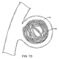
本発明のインプラントは血管部位を塞栓するために使用することができる。このことは、以下で説明される図1A、図1B、図1C、および図1Dに最もよく示されている。この送出方法は予想される1つの実施形態であること、また、本発明のインプラントは当業者に知られた他のさまざまな方法で送出することができることに留意すべきである。
[Embolic method of blood vessel site]
The implants of the present invention can be used to embolize vascular sites. This is best illustrated in FIGS. 1A, 1B, 1C, and 1D described below. It should be noted that this delivery method is one anticipated embodiment and that the implant of the present invention can be delivered in various other ways known to those skilled in the art.
図1Aに示された実施形態では、オペレータが案内用カテーテル112を使用して、マイクロカテーテル114を患者の血管系の中に位置決めする。この処置には、案内用カテーテル112を鼠径部のような進入箇所を介して患者の血管系の中へ挿入することと、案内用カテーテル112の遠位端112aをそれが頸動脈へ到達するまで血管系を介して導入することが含まれている。案内用ワイヤ(図示略)を案内用カテーテル112から取り外した後に、マイクロカテーテル114が案内用カテーテル112の中へ挿入され、そしてその後、マイクロカテーテル114の遠位端114aが、案内用カテーテル遠位端112aから出て、患者の脳の中の動脈瘤のような標的部位116の近傍に置かれる。図1Bおよび図1Cに示されたように、マイクロカテーテル114には、一般的な画像化システムでマイクロカテーテル114の遠位端114aの画像化を容易にするマイクロカテーテルマーカー115および115aが含まれており、また、図示されたこの実施形態では、マイクロカテーテルマーカー115および115aは放射線不透過性材料から作られている。遠位端114aが標的部位116に到達すると、図示されたこの実施形態の位置決めシステム(図示略)は、その後、マイクロカテーテル114の中へ挿入されて、図1Cに示されたように、インプラントインターフェイス180を、標的部位116の近傍でポジショナー140の遠位端に位置決めする。この処置の間にインプラント190が送出されるときには、インプラント190は、位置決めシステムをマイクロカテーテル114の中へ挿入するのに先立って、インプラントインターフェイス180へ取り付けられる。インプラント送出のこのモードは、図1A、図1B、および図1Cに示されている。
In the embodiment shown in FIG. 1A, an operator uses the guiding
インプラント190の送出は、マイクロカテーテルマーカー115aを標的部位116の近傍に置くことと、マイクロカテーテルマーカー115をポジショナー140におけるポジショナーマーカー164に位置合せすることとによって、容易になり、図1Cに示されたように、これら2つのマーカー(マーカー115および164)が互いに位置合せされると、インプラントインターフェイス180がインプラント190を位置決めシステム(図示略)から取り外すための適切な位置にある、ということがオペレータに示される。インプラント190が標的部位116に置かれた後に、第2インプラント190を標的部位116に置くことができるが、このことは、この位置決めシステムをマイクロカテーテル114から取り外し、その後、第1インプラント190の挿入において使用された方法に類似したやり方によって、取り付けられた第2インプラント190で第2位置決めシステムをマイクロカテーテル114の中へ挿入して行われる。臨床的に必要であれば、同じ処置を第3インプラント190およびそれに続くインプラントのために使用することができる。インプラント190が、回収されるかあるいは再位置決めされるために患者の体内にすでにあるときには、この位置決めシステムは、インプラント190によることなくマイクロカテーテル114の中へ挿入される。
Delivery of the
マンドレル、インプラント、およびインプラント製造方法
本発明は、1つの実施形態では、巻き付けパターンに適合するように偏倚(バイアス)されたコイル長さのあるインプラントに関するものであり、その巻き付けパターンは球体の外側表面の形状にほぼ適合している。この巻き付けパターンには、その形状を覆うように配置された、少なくとも1つの閉じられていないメビウスループ(あるいは、複数の閉じられていないメビウスループ)がある。メビウスループは、そのコイルの両端部の方向を変えるとともに、これら両端部を接合する前に一方端部を半回折り返すことによって形成されるものである。このことは、図7Cに最もよく示されている。本発明において、メビウスループが閉じられていないということは、両端部が接合されていないという意味である。メビウスループは、単一の表面を有している細長片であるとともに対掌性のものである。
BACKGROUND OF THE INVENTION The present invention, in one embodiment, relates to a coiled implant that is biased (biased) to conform to a winding pattern, the winding pattern being the outer surface of a sphere. It almost fits the shape of This winding pattern has at least one unclosed Mobius loop (or a plurality of unclosed Mobius loops) arranged to cover the shape. The Mobius loop is formed by changing the direction of both end portions of the coil and half-folding one end portion before joining the both end portions. This is best illustrated in FIG. 7C. In the present invention, that the Mobius loop is not closed means that both ends are not joined. Mobius loops are strips having a single surface and are antipodal.
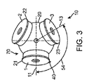
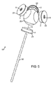
メビウスループを実現するために、マンドレルが採用されている。図2および図3に示されたマンドレル10には、球体20、4つのマーカー、および必要に応じて軸部30が含まれている。これらのマーカーは、4つの箇所で球体20の外側表面に取り付けられている。それぞれのマーカーは、図2および図3に示されたように、1、2、3、あるいは4の数字識別子で表示されている。具体的には、軸部30はマーカー4から延出している。マーカー1は、図2および図3の左側にあり、また、始動用チューブ40を含むので識別可能である。マーカー3は、図2ではマーカー1の右側にあり、図3では底部の右側にある。マーカー2は、図2では、図の後方側にあるために見ることができないが、図3では、頂部の右側に示されている。図5には、始動用チューブ40のないマンドレル10の等角組立図が示されている。
A mandrel is used to realize the Mobius loop. The
マーカー1、2、3、および4は、円筒状であって、マーカー1、2、3、および4のための長手軸11、12(示されていないが、マーカー2を通る軸をいう)、13、および14をそれぞれ画定している。それぞれの軸11、12、13、および14は球体20の中心を通っている。長手軸14はまた、軸部30の中心も通っている。軸11、12、および13は、図2に示されたように、軸14に直交する平面52に対する対頂角50の位置にあり、この対頂角は約19.5度±2.5度である。軸11、12、および13は、図3に示されたように、互いに対して水平角54をなす位置にあり、この水平角は約120度±5度である。
球体20の中心に対するそれぞれのマーカー1、2、3、および4の半径方向の一番端には、必要に応じてキャップ21、22、23、および24がある。それぞれのキャップ21、22、23、および24には、対応するマーカー1、2、3、および4の外径よりも大きい外径がある。これらのマーカーおよびキャップの外径寸法と球体20の外径とは、マンドレル10の大きさによって変わるのが好ましい。マンドレル10の大きさは、このマンドレル10で形成されるコイル60の大きさに対応している。
マーカー1、2、3、および4は、球体20の外側表面に配置されており、また、それぞれのマーカー1、2、3、および4には、球体20の外径よりも小さい外径があるが、この外径によって、球体20の表面におけるそれぞれのマーカー1、2、3、および4どうしの間に間隔70が設けられている。それぞれのマーカー1、2、3、および4どうしの間におけるこの間隔70によって、それぞれのマーカー1、2、3、および4どうしの間に、球体20の表面に十字状に交差する通路72(図6)が設けられている。この通路72によって、それぞれのマーカー1、2、3、および4どうしの間における間隔70の球体20の外側表面の周りに巻き付けられるコイル60のための巻き付けパターン74(図7Aおよび図7B)が規定されている。
マーカー1、2、3、および4の直径は、所望の柔軟性および強度のコイルを設けるために選定されている。コイルの柔軟性によって、上記血管部位へ適合するコイルの機能が決定される。マーカー1、2、3、および4の直径が大きければ大きいほど、上記ループは大きくなり、コイルは柔らかくなり、コイルは上記血管部位へいっそう良好に適合することができる。本発明の1つの実施形態では、上記球体の直径に対するマーカー1、2、3、および4の直径の比は、約0.5〜約0.75、あるいは0.55〜約0.75、あるいは約0.61〜約0.65、あるいは約0.63である。
The diameters of
巻き付けパターン74は、図5に示されたように、マーカー1における始動用チューブ40で始まる。1つの実施形態では、コイル60を始動用チューブ40に固定するために、巻き付けられるコイル60の一方端部が始動用チューブ40に挿入される。コイル60の初めの巻き付けは、一回の巻き付けが達成されるまで、マーカー1の外径表面の周りで行われる。一回の巻き付けとは、270度の周辺角から360度の周辺角までである巻き付けをいう。一回の巻き付けが達成された後に、コイル60は、隣接するマーカー1、2、3、および4どうしの間における間隔70の球体20の表面に沿って配置された通路72に沿って巻き付けられるが、この通路72は、初めの巻き付けの後にはこれらのマーカーの外径表面に沿って配置されていない。
The winding
コイル60の巻き付けのために使用される巻き付けパターン74は、球体20の外側表面における通路72に従う。図6に示されたように、この通路72は、隣接するマーカーどうしの間における球体の表面の中間点80に近づくまで、それぞれのマーカー1、2、3、および4に隣接して連続状に伸びている。図6に示されたように、中間点1−3は、マーカー1および3の間における中間点80に配置されている(80(1−3))。同様な中間点80は、それぞれのマーカーどうしの間における球体に、次のように表示された合計6つの中間点に置かれている。1−2(マーカー1および2の間)、1−3(マーカー1および3の間)、1−4(マーカー1および4の間)、2−3(マーカー2および3の間)、2−4(マーカー2および4の間)、および3−4(マーカー3および4の間)。通路72がそれぞれの中間点80に近づくと、その通路72は、1つのマーカーに隣接する位置から離れて異なるマーカーに隣接する位置へ向かって移動する。図6に示されたように、その通路72は、マーカー3に隣接する第1位置82から中間点1−3へ、次いでマーカー2に隣接する第2位置84へ進む。
The winding
図6、図7Aおよび図7Bからわかるように、巻き付けパターン74は、球体20の表面にわたって実質的三角形90のパターンを描く通路72に従うが、ここで、それぞれの三角形90の頂点91は中間点80に配置されている。さらにわかるように、2つの型の実質的三角形90が明らかである。一方の型の実質的三角形は、それぞれのマーカー1、2、3、および4を包囲しているとともに、これらのマーカーの軸11、12、13、および14から離れて外側へ湾曲する側面を有している。他方の型の実質的三角形は、これらのマーカー1、2、3、および4どうしの間に配置されているとともに、この三角形の中心へ向かって、かつ、これらのマーカーの頂点から離れて対応して湾曲する側面を有している。図7Aに破線で示されたように、合計4つの外方湾曲した三角形92と合計4つの内方湾曲した三角形94とが形成されており、これらはともに、球体20の外側表面の形状に従っている。
As can be seen from FIGS. 6, 7A and 7B, the
用語「実質的三角形」とは、いずれかのあるいはすべての辺を規定する線が直線、凸状曲線あるいは凹状曲線である3辺形をいう、ことに留意すべきである。加えて、実質的三角形が球体の表面に置かれているときには、そのように形成された形状が、二次元ではなくて、下にある球体の三次元表面構造に適合するであろう、ということが理解される。 It should be noted that the term “substantially triangular” refers to a triangle with a line defining any or all sides being a straight line, a convex curve or a concave curve. In addition, when a substantial triangle is placed on the surface of the sphere, the shape so formed will match the three-dimensional surface structure of the underlying sphere, not two-dimensional. Is understood.
図8は、通路72によって通過されたマーカー1、2、3、および4に関する巻き付けパターン74を典型的に示している。図7Aの頂部左隅に表示されるように、巻き付けパターン74はマーカー1の始動用チューブ40で始まり、これは番号1の付いた円によって表されており、また、その初めの巻き付けは、マーカー1の周りの巻き付けに示されている。マーカー1の周りの初めの巻き付けに続いて、巻き付けパターン74は、示されたように、マーカー4に隣接する位置へ、次いでマーカー2に隣接する位置へ、などのように進む。この巻き付けパターン74は、全コイル60がマンドレル10の周りに巻き付けられるまで、その後、繰り返される。巻き付け部の長さはコイルの大きさに左右される。
FIG. 8 typically shows a
巻き付けパターン74は、マーカー1の周りの初めの巻き付けの後に連続状に横断される中間点80を参照することによってもまた、表すことができる。従って、図8によって表された巻き付けパターンの初めの部分は、マーカー1の周りの初めの巻き付けの後に巻き付けパターン74によって横断された中間点の次のパターンによって表すことができる。1−4、2−4、2−3、3−4、2−4、1−2、1−3、3−4、など。
The winding
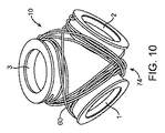
コイル60が形成されるとき、そのコイルは、始動用チューブ40(図示略)に配置されたコイル60の始動で、巻き付けパターン74に従ってマンドレル10の周りに巻き付けられる。コイル60の端部が巻き付け過程に達すると、コイル60の一部分は、球体20の周りに時々巻き付けられず、代わりに軸部30(図示略)の周りに巻き付けられ、また、そのコイルの端部を定位置に固定するために引き伸ばされる。図9および図10はマンドレル10および巻き付けコイル60を示している。この巻き付けコイル60はその後、当業界において知られたプロセスに類似した熱処理プロセスを受けるが、このプロセスによって、コイル60はその後、マンドレル20の巻き付けパターン74への偏倚(バイアス)が備わるように、すなわち、マンドレル20の巻き付けパターン74に類似したパターンの傾向がコイルに備わるようになる。コイル60がこの熱処理プロセスを受けた後に、そのコイルはマンドレル20から取り外され、さらに処理される。このさらに別の処理には、次の節に記載された改質が含まれているのが好ましい。加えて、コイル60には、らせんである一次的構造が備わっていてもよい。
When the
マンドレル10で巻き付けパターン74を付与することと上記熱処理とで形成されたコイル60には、図7Aおよび図7Bに示されたループパターンが備わっているであろう。好ましいのは、巻き付けパターン74に対応する形状を形成するために、コイル60が偏倚(バイアス)されて、図7Aに模式的に表されたように、球体20の外径形状をほぼ形成するように均等に置かれて球面状に湾曲された8つの実質的三角形のパターンがコイル60に備わっていることである。コイル60のこのパターンが、形状92に対応する一組4つの外方湾曲状の実質的三角形と形状94に対応する合計4つの内方湾曲状の実質的三角形とを形成している、こともまた好ましい。コイル60の長さに左右されるが、図9および図10に示されたように、少なくとも1回の、また、好ましくは複数回のコイルの巻き付けが、巻き付けパターン74によってマンドレル10の周りで行われるであろう。
The
後方対向部分が簡略化のために省略された図7Aの巻き付けパターン74の前方対向部分を示す図7Bに示されたように、巻き付けパターン74には、形状92および94に対応するループ1、ループ2、およびループ3として表された3つのループが含まれている。図7Bからわかるように、巻き付けパターン74のループ1、ループ2、およびループ3の各部分は、隣接する形状92および94の間に配置された通路に従い、ループ1の通路に沿って位置を変える。ループ1の通路において、箇所96では、ループ1は一方側面における形状92と他方側面における形状94との間にある。ループ1の通路のもっと先に沿った箇所98では、ループ1に対する形状92および94の相対位置は、ループ1が一方側面における形状94と他方側面における形状92との間にあるように、変えられている。図6および図10からもわかるように、形状92および94の同じ変更が巻き付けパターン74の後方対向部分において行われるとともに、形状92および94の同じ変更が巻き付けパターン74のループ2の部分およびループ3の部分に関して行われる。図6および図7A−Bからわかるさらに別のことは、巻き付けパターン74のループ1,2、および3が、球体20の中心の周りで湾曲しているとともに形状92および94に対応する少なくとも4つの箇所の周りでもまた湾曲している通路に従うということであるが、このことは、双曲放物面の輪郭あるいは鞍の輪郭に概ね従うように説明することができる。このことは図7Bに示されている。
As shown in FIG. 7B showing the front facing portion of the winding
[材料]
1つの実施形態では、コイル60は、体内で使用されるときに組織および体液に悪影響を及ぼすことのない生体適合性の金属から作られている。このワイヤは、円形、正方形、楕円形、三角形、あるいは別の形状でもよい。ある実施形態では、このワイヤには一般に、約0.025〜約0.09mm、約0.03〜約0.08mm、約0.04〜約0.06mmの直径がある。ある特定の実施形態では、このワイヤには約0.05mmの直径がある。いくつかの実施形態では、このワイヤは、一次的形状、例えば、単純な単一らせんからだけ構成することができる。いくつかの実施形態では、このワイヤ構成要素は、例えばらせんコイルのような一次的形状と、二次的形状とから構成することができる。
[material]
In one embodiment,
1つの実施形態では、コイル60の素材は、およそ400℃〜約700℃の温度で熱設定される材料から作られている。いくつかの実施形態では、このコイルは約650℃で熱設定される。上記の金属あるいは合金は、体内におけるインプラントの位置および区域を放射線技術で監視することができるように、放射線不透過性である。適切な金属には、イリジウム、金、銀、タングステンおよびタンタルはもとより、白金、パラジウム、ロジウムおよびレニウムが含まれる白金族金属のような貴金属、およびこれらの金属と互いとの合金が含まれるが、これらに限定されることはない。付加的な金属には、「ニチノール」などのような超弾性金属が含まれる。1つの実施形態では、コイル60は白金合金から作られている。
In one embodiment, the material of the
本発明のマンドレルは、選択された材料がこのコイルの上記熱設定に耐えることができる限り、鋼鉄のようなさまざまな材料から作ることができる。 The mandrel of the present invention can be made from a variety of materials, such as steel, so long as the selected material can withstand the above heat setting of the coil.
[コイルの改造および送出]
上記のように、本発明のコイルは、改造が含まれるさらに別の処理を受けることもでき、また、他の諸構成要素が備わっているインプラントとともに使用することもできる。1つの実施形態では、このインプラントは、この明細書と同日に代理人整理番号355492−7551として提出され、かつ、発明の名称が「コイルおよび耐伸張性部材が含まれているインプラント」であり、その内容が参照によってこの明細書に引用されている米国特許出願番号第12/ , ,号明細書の中に記載されたような耐伸張性部材が含まれるように改造されている。
[Coil modification and delivery]
As noted above, the coils of the present invention can be subjected to further processing including modifications and can be used with implants that include other components. In one embodiment, the implant is filed on behalf of this specification as attorney docket number 3549492-7551, and the name of the invention is “an implant that includes a coil and a stretch resistant member”; 12 / US patent application No., the contents of which are cited herein by reference, and the stretch-resistant member as set forth in Pat are modified to include.
別の実施形態では、コイルは送出装置に連結されている。コイルを血管部位へ送出するのに適した任意の送出装置を採用することができる。適切なマイクロカテーテルは、発明の名称が「機械的位置決め用血管内インプラントのためのシステムおよび方法」であって、参照によってその全体がこの明細書の中に引用されている国際特許出願公開(WO)第2007/121405号パンフレットの中に記載されている。 In another embodiment, the coil is coupled to a delivery device. Any delivery device suitable for delivering the coil to the vascular site can be employed. A suitable microcatheter is entitled “Systems and Methods for Mechanical Positioning Endovascular Implants” and is incorporated herein by reference in its entirety. ) It is described in the 2007/121405 pamphlet.
採用された送出装置のいかんにかかわらず、上記血管部位へのこのインプラントの送出の後に、このインプラントは、その三次元形状によって、上記血管部位へ実質的に適合する。このことは図1Dに示されている。 Regardless of the delivery device employed, after delivery of the implant to the vascular site, the implant substantially conforms to the vascular site by virtue of its three-dimensional shape. This is illustrated in FIG. 1D.
[実施例]
[実施例1−インプラントの製造方法]
本発明のインプラントは次の手順によって作ることができる。
1.マイクロスコープのもとで、上記のワイヤあるいはコイルの遠位端を始動用チューブの中へ挿入する。
2.上で、また図8において記載されたように、上記コイルをマンドレルの周りに巻き付ける。
3.上記コイルおよび上記マンドレルを熱設定する。その温度は約550℃〜約650度である。
[Example]
[Example 1-Implant manufacturing method]
The implant of the present invention can be made by the following procedure.
1. Under the microscope, the distal end of the wire or coil is inserted into the starter tube.
2. The coil is wrapped around the mandrel as described above and in FIG.
3. The coil and the mandrel are heat set. The temperature is about 550 ° C. to about 650 degrees.
[実施例2−他の三次元形状の比較]
本発明のコイルは、試験されて、立方体状三次元(3−D)形状および球状(あるいは回転楕円体状)3−D形状を有しているコイルと比較された。臨床医は、上記血管部位の中へ詰めるためのコイルの機能と、上記血管部位の形状に適合するためのコイルの機能とを評価した。
[Example 2-Comparison of other three-dimensional shapes]
The coils of the present invention were tested and compared to coils having a cubic three-dimensional (3-D) shape and a spherical (or spheroid) 3-D shape. The clinician evaluated the function of the coil to fit into the vascular site and the function of the coil to conform to the shape of the vascular site.
[実験記録]
本発明のコイルは実施例1によって得られた。本発明のメビウスループコイルは、4つの8ミリメートル(mm)マーカーがある10ミリメートル球体に作られた。立方体3−Dを有しているコイルは、6つのマーカー(本発明のコイルを得るためには4つのマーカーと違って)を有しているマンドレルの周りにワイヤを上記立方体のそれぞれの面に1回巻き付けることで、作られた。1つのマーカーは5mmであり、他の5つのマーカーは8mmであった。上記球体は10mmであった。8つのマーカーがあるベースマンドレルの周りにワイヤを巻き付けることによって、球状コイルが得られた。この球体は再び10mmであったし、また、上記マーカーは約5mmであった。
[Experimental record]
The coil of the present invention was obtained according to Example 1. The Mobius loop coil of the present invention was made into a 10 millimeter sphere with four 8 millimeter (mm) markers. A coil with a cube 3-D has a wire on each side of the cube around a mandrel with 6 markers (unlike 4 markers to obtain the coil of the present invention). Made by wrapping once. One marker was 5 mm and the other 5 markers were 8 mm. The sphere was 10 mm. A spherical coil was obtained by winding a wire around a base mandrel with 8 markers. The sphere was again 10 mm and the marker was about 5 mm.
上記コイルが上記パターンによっていったん巻き付けられると、上記コイルは以下で付与された温度で熱設定された。 Once the coil was wound by the pattern, the coil was heat set at the temperature given below.
ブタにおいて、10ミリメートルの動脈瘤が作り出された。10ミリメートル×30センチメートルのコイルが、それを取り外した後にそれを上記カテーテルから取り出すとともに次のコイルを配置する、ということなく、その動脈瘤の中へ数回、置かれた。このことは図1Dに示されている。 In the pig, a 10 millimeter aneurysm was created. A 10 millimeter by 30 centimeter coil was placed several times into the aneurysm without removing it from the catheter and placing the next coil after it was removed. This is illustrated in FIG. 1D.
これらのコイルを目隠しフォーマットにおいて試験した臨床医は、次いで、そのコイルを上記動脈瘤へ送出するとともに、そのコイルに関する定量的フィードバックを提供した。次いで、独立した観察者が、それぞれのコメントを+1(よい)、0(普通)、−1(悪い)基準に解釈した。いくつかのコイルは、医師のコメントによって、ある基準でより高くマークが付けられた。上記メビウスループコイルのうちの3本のコイル、上記球状コイルのうちの3本のコイル、および上記立方体コイルのうちの1本のコイルが評価された。試験されたコイルのうちのいくつかには、以下に示すように耐伸張性部材が含まれていた。この結果は表1に表されている。 Clinicians who tested these coils in a blindfold format then delivered the coils to the aneurysm and provided quantitative feedback on the coils. An independent observer then interpreted each comment on a +1 (good), 0 (normal), -1 (bad) basis. Some coils were marked higher on some criteria, according to physician comments. Three of the Moebius loop coils, three of the spherical coils, and one of the cubic coils were evaluated. Some of the coils tested included stretch resistant members as shown below. The results are shown in Table 1.

この試験は、その後、耐伸張性部材が表されたように変化したことを除いて、繰り返された。また、上記基準は、0(悪い)から5(よい)までの基準で評価された。この結果は表2に表されている。 This test was then repeated, except that the stretch resistant member changed as shown. Moreover, the said reference | standard was evaluated by the reference | standard from 0 (bad) to 5 (good). The results are shown in Table 2.
表1および表2からわかるように、メビウスループコイルは、その総合性能と立方体コイルおよび球体コイルに優る反復性のために好ましい。 As can be seen from Tables 1 and 2, Mobius loop coils are preferred because of their overall performance and repeatability over cube and sphere coils.
本発明はいくつかの実施形態を参照しながら開示されてきたが、本発明の領域および範囲から逸脱することなく、特許請求の範囲で定義されたように、記載された実施形態に対する多数の改造、修正、および変更が可能である。従って、本発明は記載された実施形態に限定されることがないということが意図されているが、本発明には、次の特許請求の範囲の言語とその同等物とによって定義された完全な範囲がある。 Although the present invention has been disclosed with reference to several embodiments, numerous modifications to the described embodiments as defined in the claims without departing from the scope and scope of the present invention. , Modifications, and changes are possible. Accordingly, it is intended that the invention not be limited to the described embodiments, but the invention includes a complete language defined by the language of the following claims and their equivalents. There is a range.
Claims (9)
前記巻き付けパターンは、球体の外側表面の形状にほぼ適合しており、前記巻き付けパターンは、前記形状を覆うように配置された複数の閉じられていないメビウスループを有し、
前記巻き付けパターンは、前記形状を覆うように配置された8つの実質的に三角形の部分をさらに含み、前記三角形は、中心を有し、前記三角形のうちの4つは、前記中心から外側に向かって湾曲している辺を有し、前記三角形のうちの4つは、前記中心に向かって内側に湾曲している辺を有する、インプラント。 The implant containing the three-dimensional intravascular coils to have a biased coil length to fit the winding pattern,
The winding pattern is substantially adapted to the shape of the outer surface of a sphere, the winding pattern has a plurality of unclosed Mobius loop arranged so as to cover the shape,
The winding pattern further includes eight substantially triangular portions arranged to cover the shape, the triangle having a center, four of the triangles facing outward from the center. Implants having four sides that are curved and four of the triangles have sides that are curved inward toward the center .
初めの巻き付けを形成するために、前記マンドレルのマーカーの周りに前記コイルを巻き付けることであって、前記コイルは、巻き付けパターンに適合するように偏倚された長さを有し、前記巻き付けパターンは、球体の外側表面の形状にほぼ適合している、ことと、
前記コイルを前記マンドレルの表面に配置された4つのマーカーのそれぞれの間で前記マンドレルの表面を横切るように巻き付けることにより、複数の閉じられていないメビウスループを提供することであって、前記巻き付けことは、隣接する2つのマーカーのそれぞれの間に前記マンドレルの外側表面の中間に配置された複数の中間点のそれぞれにおいて前記コイルを前記コイル自身を横切るように交差させることを含む、ことと
を含み、
前記巻き付けパターンは、前記形状を覆うように配置された8つの実質的に三角形の部分をさらに含み、前記三角形は、中心を有し、前記三角形のうちの4つは、前記中心から外側に向かって湾曲している辺を有し、前記三角形のうちの4つは、前記中心に向かって内側に湾曲している辺を有する、方法。 A method of forming a three-dimensional intravascular coil using a mandrel , the method comprising:
Winding the coil around the mandrel marker to form an initial wrap , the coil having a length biased to fit a wrapping pattern, the wrapping pattern comprising: Almost conforms to the shape of the outer surface of the sphere,
The Rukoto winding the coil across the surface of the mandrel between each of the four markers placed on the surface of the mandrel, the method comprising: providing a Mobius loop that is not a plurality of closed, the winding it involves crossing the coil across the coil itself in each of a plurality of intermediate points which are located intermediate the outer surface of the mandrel between each two adjacent markers, it and
Including
The winding pattern further includes eight substantially triangular portions arranged to cover the shape, the triangle having a center, four of the triangles facing outward from the center. And four of the triangles have sides that are curved inward toward the center .
Further comprising the method of claim 8, removing the coil from the mandrel.
Applications Claiming Priority (7)
| Application Number | Priority Date | Filing Date | Title |
|---|---|---|---|
| US89458907P | 2007-03-13 | 2007-03-13 | |
| US60/894,589 | 2007-03-13 | ||
| US89486507P | 2007-03-14 | 2007-03-14 | |
| US89485807P | 2007-03-14 | 2007-03-14 | |
| US60/894,865 | 2007-03-14 | ||
| US60/894,858 | 2007-03-14 | ||
| PCT/US2008/055179 WO2008112436A2 (en) | 2007-03-13 | 2008-02-27 | An implant, a mandrel, and a method of forming an implant |
Publications (3)
| Publication Number | Publication Date |
|---|---|
| JP2010521232A JP2010521232A (en) | 2010-06-24 |
| JP2010521232A5 JP2010521232A5 (en) | 2011-04-14 |
| JP5227344B2 true JP5227344B2 (en) | 2013-07-03 |
Family
ID=39705035
Family Applications (1)
| Application Number | Title | Priority Date | Filing Date |
|---|---|---|---|
| JP2009553681A Active JP5227344B2 (en) | 2007-03-13 | 2008-02-27 | Implant, mandrel, and implant formation method |
Country Status (8)
| Country | Link |
|---|---|
| US (1) | US8801747B2 (en) |
| EP (1) | EP2124763B1 (en) |
| JP (1) | JP5227344B2 (en) |
| KR (1) | KR20100015521A (en) |
| CN (1) | CN101677821B (en) |
| AU (1) | AU2008226695B2 (en) |
| CA (1) | CA2680793C (en) |
| WO (1) | WO2008112436A2 (en) |
Families Citing this family (48)
| Publication number | Priority date | Publication date | Assignee | Title |
|---|---|---|---|---|
| US8048104B2 (en) | 2000-10-30 | 2011-11-01 | Dendron Gmbh | Device for the implantation of occlusion spirals |
| US8425549B2 (en) | 2002-07-23 | 2013-04-23 | Reverse Medical Corporation | Systems and methods for removing obstructive matter from body lumens and treating vascular defects |
| DE102004003265A1 (en) | 2004-01-21 | 2005-08-11 | Dendron Gmbh | Device for the implantation of electrically isolated occlusion coils |
| DE602005025215D1 (en) * | 2004-05-21 | 2011-01-20 | Micro Therapeutics Inc | METAL COILS EMBOSSED BY ORGANIC OR BIODEGRADABLE OR SYNTHETIC POLYMERS OR FIBERS FOR THE EMBOLIZATION OF A BODY HEIGHT |
| ES2321300T3 (en) | 2004-09-22 | 2009-06-04 | Dendron Gmbh | MEDICAL IMPLANT |
| US8845676B2 (en) * | 2004-09-22 | 2014-09-30 | Micro Therapeutics | Micro-spiral implantation device |
| US8864790B2 (en) | 2006-04-17 | 2014-10-21 | Covidien Lp | System and method for mechanically positioning intravascular implants |
| US8777979B2 (en) | 2006-04-17 | 2014-07-15 | Covidien Lp | System and method for mechanically positioning intravascular implants |
| JP5227344B2 (en) | 2007-03-13 | 2013-07-03 | タイコ ヘルスケア グループ リミテッド パートナーシップ | Implant, mandrel, and implant formation method |
| JP5249249B2 (en) | 2007-03-13 | 2013-07-31 | コヴィディエン リミテッド パートナーシップ | Implant including a coil and a stretch resistant member |
| US10123803B2 (en) | 2007-10-17 | 2018-11-13 | Covidien Lp | Methods of managing neurovascular obstructions |
| US9220522B2 (en) | 2007-10-17 | 2015-12-29 | Covidien Lp | Embolus removal systems with baskets |
| US11337714B2 (en) | 2007-10-17 | 2022-05-24 | Covidien Lp | Restoring blood flow and clot removal during acute ischemic stroke |
| US8066757B2 (en) | 2007-10-17 | 2011-11-29 | Mindframe, Inc. | Blood flow restoration and thrombus management methods |
| US9198687B2 (en) | 2007-10-17 | 2015-12-01 | Covidien Lp | Acute stroke revascularization/recanalization systems processes and products thereby |
| US8088140B2 (en) | 2008-05-19 | 2012-01-03 | Mindframe, Inc. | Blood flow restorative and embolus removal methods |
| US8926680B2 (en) | 2007-11-12 | 2015-01-06 | Covidien Lp | Aneurysm neck bridging processes with revascularization systems methods and products thereby |
| US8585713B2 (en) | 2007-10-17 | 2013-11-19 | Covidien Lp | Expandable tip assembly for thrombus management |
| JP5457373B2 (en) | 2008-02-22 | 2014-04-02 | コヴィディエン リミテッド パートナーシップ | Device for blood flow recovery |
| CN101977650A (en) | 2008-04-11 | 2011-02-16 | 曼德弗雷姆公司 | Monorail neuro-microcatheter for delivery of medical devices to treat stroke, processes and products thereby |
| US20130289690A1 (en) | 2011-11-01 | 2013-10-31 | Hira V. Thapliyal | Personalized prosthesis and methods of use |
| US9579104B2 (en) | 2011-11-30 | 2017-02-28 | Covidien Lp | Positioning and detaching implants |
| US9011480B2 (en) | 2012-01-20 | 2015-04-21 | Covidien Lp | Aneurysm treatment coils |
| US9687245B2 (en) | 2012-03-23 | 2017-06-27 | Covidien Lp | Occlusive devices and methods of use |
| US9326774B2 (en) | 2012-08-03 | 2016-05-03 | Covidien Lp | Device for implantation of medical devices |
| US9713475B2 (en) | 2014-04-18 | 2017-07-25 | Covidien Lp | Embolic medical devices |
| US20150327868A1 (en) * | 2014-05-13 | 2015-11-19 | Ndi Tip Teknolojileri Anonim Sirketi | Retractable and rapid disconnect, floating diameter embolic coil product and delivery system |
| US9808256B2 (en) | 2014-08-08 | 2017-11-07 | Covidien Lp | Electrolytic detachment elements for implant delivery systems |
| US9814466B2 (en) | 2014-08-08 | 2017-11-14 | Covidien Lp | Electrolytic and mechanical detachment for implant delivery systems |
| US10857012B2 (en) | 2015-01-20 | 2020-12-08 | Neurogami Medical, Inc. | Vascular implant |
| US11484319B2 (en) | 2015-01-20 | 2022-11-01 | Neurogami Medical, Inc. | Delivery system for micrograft for treating intracranial aneurysms |
| US10736730B2 (en) | 2015-01-20 | 2020-08-11 | Neurogami Medical, Inc. | Vascular implant |
| JP6763864B2 (en) | 2015-01-20 | 2020-09-30 | ニューロガミ メディカル インコーポレイテッド | Micrografts and usage for the treatment of intracranial aneurysms |
| US10925611B2 (en) | 2015-01-20 | 2021-02-23 | Neurogami Medical, Inc. | Packaging for surgical implant |
| WO2016125704A1 (en) * | 2015-02-06 | 2016-08-11 | 株式会社カネカ | Mould for producing in-vivo indwelling member, and in-vivo indwelling member production method using said mould |
| JP2018522601A (en) | 2015-04-22 | 2018-08-16 | アニュメド, インコーポレイテッド | Personalized prostheses and deployment methods |
| US9717503B2 (en) | 2015-05-11 | 2017-08-01 | Covidien Lp | Electrolytic detachment for implant delivery systems |
| CN108472043B (en) * | 2015-12-30 | 2022-05-31 | 斯瑞克公司 | Embolization device and method of making same |
| JP2019516425A (en) * | 2016-05-13 | 2019-06-20 | コヴィディエン リミテッド パートナーシップ | Aneurysm treatment coil |
| US10531876B2 (en) * | 2016-05-31 | 2020-01-14 | Spartan Micro, Inc. | Systems and methods for delivering intravascular implants |
| US10828039B2 (en) | 2016-06-27 | 2020-11-10 | Covidien Lp | Electrolytic detachment for implantable devices |
| US10828037B2 (en) | 2016-06-27 | 2020-11-10 | Covidien Lp | Electrolytic detachment with fluid electrical connection |
| US11051822B2 (en) | 2016-06-28 | 2021-07-06 | Covidien Lp | Implant detachment with thermal activation |
| US10420563B2 (en) | 2016-07-08 | 2019-09-24 | Neurogami Medical, Inc. | Delivery system insertable through body lumen |
| US11399840B2 (en) | 2019-08-13 | 2022-08-02 | Covidien Lp | Implantable embolization device |
| WO2022040683A1 (en) * | 2020-08-18 | 2022-02-24 | Balt Usa, Llc | Vascular embolic implant |
| JP2023538288A (en) | 2020-08-21 | 2023-09-07 | シェイプ メモリー メディカル,インコーポレイテッド | Mechanical separation system for transcatheter devices |
| CN113288315A (en) * | 2021-06-21 | 2021-08-24 | 上海鸿脉医疗科技有限公司 | Medical implant and manufacturing method thereof |
Family Cites Families (421)
| Publication number | Priority date | Publication date | Assignee | Title |
|---|---|---|---|---|
| US3334629A (en) | 1964-11-09 | 1967-08-08 | Bertram D Cohn | Occlusive device for inferior vena cava |
| US3834394A (en) | 1969-11-21 | 1974-09-10 | R Sessions | Occlusion device and method and apparatus for inserting the same |
| US4085757A (en) | 1976-04-29 | 1978-04-25 | P Pevsner | Miniature balloon catheter method and apparatus |
| US4341218A (en) | 1978-05-30 | 1982-07-27 | University Of California | Detachable balloon catheter |
| US4327734A (en) | 1979-01-24 | 1982-05-04 | White Jr Robert I | Therapeutic method of use for miniature detachable balloon catheter |
| US4282875A (en) | 1979-01-24 | 1981-08-11 | Serbinenko Fedor A | Occlusive device |
| US4346712A (en) | 1979-04-06 | 1982-08-31 | Kuraray Company, Ltd. | Releasable balloon catheter |
| US4311146A (en) | 1980-05-08 | 1982-01-19 | Sorenson Research Co., Inc. | Detachable balloon catheter apparatus and method |
| US4364392A (en) | 1980-12-04 | 1982-12-21 | Wisconsin Alumni Research Foundation | Detachable balloon catheter |
| US4545367A (en) | 1982-07-16 | 1985-10-08 | Cordis Corporation | Detachable balloon catheter and method of use |
| US4441495A (en) | 1982-08-16 | 1984-04-10 | Becton, Dickinson And Company | Detachable balloon catheter device and method of use |
| US4638803A (en) | 1982-09-30 | 1987-01-27 | Rand Robert W | Medical apparatus for inducing scar tissue formation in a body |
| US4494531A (en) | 1982-12-06 | 1985-01-22 | Cook, Incorporated | Expandable blood clot filter |
| US4517979A (en) | 1983-07-14 | 1985-05-21 | Cordis Corporation | Detachable balloon catheter |
| US7166125B1 (en) | 1988-03-09 | 2007-01-23 | Endovascular Technologies, Inc. | Intraluminal grafting system |
| US4787899A (en) | 1983-12-09 | 1988-11-29 | Lazarus Harrison M | Intraluminal graft device, system and method |
| US5104399A (en) | 1986-12-10 | 1992-04-14 | Endovascular Technologies, Inc. | Artificial graft and implantation method |
| US4745919A (en) | 1985-02-01 | 1988-05-24 | Bundy Mark A | Transluminal lysing system |
| US4735201A (en) | 1986-01-30 | 1988-04-05 | The Beth Israel Hospital Association | Optical fiber with detachable metallic tip for intravascular laser coagulation of arteries, veins, aneurysms, vascular malformations and arteriovenous fistulas |
| US4719924A (en) | 1986-09-09 | 1988-01-19 | C. R. Bard, Inc. | Small diameter steerable guidewire with adjustable tip |
| FR2606641B1 (en) | 1986-11-17 | 1991-07-12 | Promed | FILTERING DEVICE FOR BLOOD CLOTS |
| DE3750480T2 (en) | 1986-11-29 | 1995-03-02 | Terumo Corp | BALLOONED CATHETER. |
| JPS63238872A (en) | 1987-03-25 | 1988-10-04 | テルモ株式会社 | Instrument for securing inner diameter of cavity of tubular organ and catheter equipped therewith |
| US4819637A (en) | 1987-09-01 | 1989-04-11 | Interventional Therapeutics Corporation | System for artificial vessel embolization and devices for use therewith |
| US6685696B2 (en) | 1987-09-30 | 2004-02-03 | Lake Region Manufacturing, Inc. | Hollow lumen cable apparatus |
| US5133732A (en) | 1987-10-19 | 1992-07-28 | Medtronic, Inc. | Intravascular stent |
| FR2632864B2 (en) | 1987-12-31 | 1990-10-19 | Biomat Sarl | ANTI-EMBOLIC ELASTIC FILTERING SYSTEM FOR CELLAR VEIN AND ASSEMBLY OF MEANS FOR ITS PLACEMENT |
| JPH0284964A (en) | 1988-03-18 | 1990-03-26 | Tokai Rika Co Ltd | High frequency power source device for balloon catheter |
| US4932419A (en) | 1988-03-21 | 1990-06-12 | Boston Scientific Corporation | Multi-filar, cross-wound coil for medical devices |
| US4832055A (en) | 1988-07-08 | 1989-05-23 | Palestrant Aubrey M | Mechanically locking blood clot filter |
| US4994069A (en) | 1988-11-02 | 1991-02-19 | Target Therapeutics | Vaso-occlusion coil and method |
| US5480382A (en) | 1989-01-09 | 1996-01-02 | Pilot Cardiovascular Systems, Inc. | Steerable medical device |
| FR2641692A1 (en) | 1989-01-17 | 1990-07-20 | Nippon Zeon Co | Plug for closing an opening for a medical application, and device for the closure plug making use thereof |
| NZ228382A (en) | 1989-03-17 | 1992-08-26 | Carter Holt Harvey Plastic Pro | Drug administering coil-like device for insertion in body cavity of animal |
| US4990155A (en) | 1989-05-19 | 1991-02-05 | Wilkoff Howard M | Surgical stent method and apparatus |
| EP0408245B1 (en) | 1989-07-13 | 1994-03-02 | American Medical Systems, Inc. | Stent placement instrument |
| US5035706A (en) | 1989-10-17 | 1991-07-30 | Cook Incorporated | Percutaneous stent and method for retrieval thereof |
| US6083220A (en) | 1990-03-13 | 2000-07-04 | The Regents Of The University Of California | Endovascular electrolytically detachable wire and tip for the formation of thrombus in arteries, veins, aneurysms, vascular malformations and arteriovenous fistulas |
| US5851206A (en) | 1990-03-13 | 1998-12-22 | The Regents Of The University Of California | Method and apparatus for endovascular thermal thrombosis and thermal cancer treatment |
| US5569245A (en) | 1990-03-13 | 1996-10-29 | The Regents Of The University Of California | Detachable endovascular occlusion device activated by alternating electric current |
| US5976131A (en) | 1990-03-13 | 1999-11-02 | The Regents Of The University At California | Detachable endovascular occlusion device activated by alternating electric current |
| US6425893B1 (en) | 1990-03-13 | 2002-07-30 | The Regents Of The University Of California | Method and apparatus for fast electrolytic detachment of an implant |
| US5122136A (en) | 1990-03-13 | 1992-06-16 | The Regents Of The University Of California | Endovascular electrolytically detachable guidewire tip for the electroformation of thrombus in arteries, veins, aneurysms, vascular malformations and arteriovenous fistulas |
| USRE42756E1 (en) | 1990-03-13 | 2011-09-27 | The Regents Of The University Of California | Endovascular electrolytically detachable wire and tip for the formation of thrombus in arteries, veins, aneurysms, vascular malformations and arteriovenous fistulas |
| US5354295A (en) | 1990-03-13 | 1994-10-11 | Target Therapeutics, Inc. | In an endovascular electrolytically detachable wire and tip for the formation of thrombus in arteries, veins, aneurysms, vascular malformations and arteriovenous fistulas |
| JP2514087Y2 (en) | 1990-05-25 | 1996-10-16 | 幸三 牧田 | Balloon with detachable double-sided check valve |
| US5108407A (en) | 1990-06-08 | 1992-04-28 | Rush-Presbyterian St. Luke's Medical Center | Method and apparatus for placement of an embolic coil |
| US5167624A (en) | 1990-11-09 | 1992-12-01 | Catheter Research, Inc. | Embolus delivery system and method |
| US5133731A (en) | 1990-11-09 | 1992-07-28 | Catheter Research, Inc. | Embolus supply system and method |
| DE4104702C2 (en) | 1991-02-15 | 1996-01-18 | Malte Neuss | Implants for organ pathways in spiral form |
| US5109867A (en) | 1991-04-19 | 1992-05-05 | Target Therapeutics | Extendable guidewire assembly |
| US5217484A (en) | 1991-06-07 | 1993-06-08 | Marks Michael P | Retractable-wire catheter device and method |
| US5147370A (en) | 1991-06-12 | 1992-09-15 | Mcnamara Thomas O | Nitinol stent for hollow body conduits |
| US5314472A (en) | 1991-10-01 | 1994-05-24 | Cook Incorporated | Vascular stent |
| CA2117088A1 (en) | 1991-09-05 | 1993-03-18 | David R. Holmes | Flexible tubular device for use in medical applications |
| US5222970A (en) | 1991-09-06 | 1993-06-29 | William A. Cook Australia Pty. Ltd. | Method of and system for mounting a vascular occlusion balloon on a delivery catheter |
| US5226911A (en) | 1991-10-02 | 1993-07-13 | Target Therapeutics | Vasoocclusion coil with attached fibrous element(s) |
| US5304194A (en) | 1991-10-02 | 1994-04-19 | Target Therapeutics | Vasoocclusion coil with attached fibrous element(s) |
| US5256146A (en) | 1991-10-11 | 1993-10-26 | W. D. Ensminger | Vascular catheterization system with catheter anchoring feature |
| US5211658A (en) | 1991-11-05 | 1993-05-18 | New England Deaconess Hospital Corporation | Method and device for performing endovascular repair of aneurysms |
| US5261916A (en) | 1991-12-12 | 1993-11-16 | Target Therapeutics | Detachable pusher-vasoocclusive coil assembly with interlocking ball and keyway coupling |
| US5234437A (en) | 1991-12-12 | 1993-08-10 | Target Therapeutics, Inc. | Detachable pusher-vasoocclusion coil assembly with threaded coupling |
| CA2084524C (en) | 1991-12-12 | 1996-07-23 | Robert H. Twyford, Jr. | Detachable pusher-vasoocclusive coil assembly with interlocking coupling |
| US5486193A (en) | 1992-01-22 | 1996-01-23 | C. R. Bard, Inc. | System for the percutaneous transluminal front-end loading delivery of a prosthetic occluder |
| WO1993020886A1 (en) | 1992-04-13 | 1993-10-28 | Ep Technologies, Inc. | Articulated systems for cardiac ablation |
| US5224953A (en) | 1992-05-01 | 1993-07-06 | The Beth Israel Hospital Association | Method for treatment of obstructive portions of urinary passageways |
| US5263964A (en) | 1992-05-06 | 1993-11-23 | Coil Partners Ltd. | Coaxial traction detachment apparatus and method |
| US5382261A (en) | 1992-09-01 | 1995-01-17 | Expandable Grafts Partnership | Method and apparatus for occluding vessels |
| US5443478A (en) | 1992-09-02 | 1995-08-22 | Board Of Regents, The University Of Texas System | Multi-element intravascular occlusion device |
| US5527338A (en) | 1992-09-02 | 1996-06-18 | Board Of Regents, The University Of Texas System | Intravascular device |
| AU4926193A (en) | 1992-09-21 | 1994-04-12 | Vitaphore Corporation | Embolization plugs for blood vessels |
| US5312415A (en) | 1992-09-22 | 1994-05-17 | Target Therapeutics, Inc. | Assembly for placement of embolic coils using frictional placement |
| US5350397A (en) | 1992-11-13 | 1994-09-27 | Target Therapeutics, Inc. | Axially detachable embolic coil assembly |
| USRE37117E1 (en) | 1992-09-22 | 2001-03-27 | Target Therapeutics, Inc. | Detachable embolic coil assembly using interlocking clasps and method of use |
| US5250071A (en) | 1992-09-22 | 1993-10-05 | Target Therapeutics, Inc. | Detachable embolic coil assembly using interlocking clasps and method of use |
| US5382259A (en) | 1992-10-26 | 1995-01-17 | Target Therapeutics, Inc. | Vasoocclusion coil with attached tubular woven or braided fibrous covering |
| US5382260A (en) | 1992-10-30 | 1995-01-17 | Interventional Therapeutics Corp. | Embolization device and apparatus including an introducer cartridge and method for delivering the same |
| US5690666A (en) | 1992-11-18 | 1997-11-25 | Target Therapeutics, Inc. | Ultrasoft embolism coils and process for using them |
| JPH08500273A (en) | 1992-11-19 | 1996-01-16 | ターゲット セラピューティクス,インコーポレイテッド | Large diameter vasoocclusive coil |
| US5443454A (en) | 1992-12-09 | 1995-08-22 | Terumo Kabushiki Kaisha | Catheter for embolectomy |
| US5423849A (en) | 1993-01-15 | 1995-06-13 | Target Therapeutics, Inc. | Vasoocclusion device containing radiopaque fibers |
| US5334210A (en) | 1993-04-09 | 1994-08-02 | Cook Incorporated | Vascular occlusion assembly |
| US5925059A (en) | 1993-04-19 | 1999-07-20 | Target Therapeutics, Inc. | Detachable embolic coil assembly |
| US5800453A (en) | 1993-04-19 | 1998-09-01 | Target Therapeutics, Inc. | Detachable embolic coil assembly using interlocking hooks and slots |
| US5498227A (en) | 1993-09-15 | 1996-03-12 | Mawad; Michel E. | Retrievable, shielded radiotherapy implant |
| US5423829A (en) | 1993-11-03 | 1995-06-13 | Target Therapeutics, Inc. | Electrolytically severable joint for endovascular embolic devices |
| US5624449A (en) | 1993-11-03 | 1997-04-29 | Target Therapeutics | Electrolytically severable joint for endovascular embolic devices |
| US6039749A (en) | 1994-02-10 | 2000-03-21 | Endovascular Systems, Inc. | Method and apparatus for deploying non-circular stents and graftstent complexes |
| US5507769A (en) | 1994-10-18 | 1996-04-16 | Stentco, Inc. | Method and apparatus for forming an endoluminal bifurcated graft |
| AU690237B2 (en) | 1994-03-03 | 1998-04-23 | Target Therapeutics, Inc. | Method for detecting separation of a vasoocclusion device |
| US5417708A (en) | 1994-03-09 | 1995-05-23 | Cook Incorporated | Intravascular treatment system and percutaneous release mechanism therefor |
| US6117157A (en) | 1994-03-18 | 2000-09-12 | Cook Incorporated | Helical embolization coil |
| WO1995025480A1 (en) | 1994-03-18 | 1995-09-28 | Cook Incorporated | Helical embolization coil |
| JP2880070B2 (en) | 1994-03-31 | 1999-04-05 | 株式会社カネカメディックス | Medical wire having an indwelling member |
| US6001092A (en) | 1994-06-24 | 1999-12-14 | Target Therapeutics, Inc. | Complex coils having fibered centers |
| US5549624A (en) | 1994-06-24 | 1996-08-27 | Target Therapeutics, Inc. | Fibered vasooclusion coils |
| US5725546A (en) | 1994-06-24 | 1998-03-10 | Target Therapeutics, Inc. | Detachable microcoil delivery catheter |
| US5522836A (en) | 1994-06-27 | 1996-06-04 | Target Therapeutics, Inc. | Electrolytically severable coil assembly with movable detachment point |
| US5725552A (en) | 1994-07-08 | 1998-03-10 | Aga Medical Corporation | Percutaneous catheter directed intravascular occlusion devices |
| CA2194671A1 (en) | 1994-07-08 | 1996-01-25 | Ev3 Inc. | Method of forming medical devices; intravascular occlusion devices |
| US5556426A (en) | 1994-08-02 | 1996-09-17 | Meadox Medicals, Inc. | PTFE implantable tubular prostheses with external coil support |
| CA2163708C (en) | 1994-12-07 | 2007-08-07 | Robert E. Fischell | Integrated dual-function catheter system for balloon angioplasty and stent delivery |
| US5690671A (en) | 1994-12-13 | 1997-11-25 | Micro Interventional Systems, Inc. | Embolic elements and methods and apparatus for their delivery |
| US5814062A (en) | 1994-12-22 | 1998-09-29 | Target Therapeutics, Inc. | Implant delivery assembly with expandable coupling/decoupling mechanism |
| DE4445715C2 (en) | 1994-12-22 | 1998-04-09 | Hans Dr Med Henkes | Arrangement for inserting an implant into a blood vessel or into a body cavity |
| US5578074A (en) | 1994-12-22 | 1996-11-26 | Target Therapeutics, Inc. | Implant delivery method and assembly |
| IL116561A0 (en) | 1994-12-30 | 1996-03-31 | Target Therapeutics Inc | Severable joint for detachable devices placed within the body |
| DK175166B1 (en) | 1995-01-03 | 2004-06-21 | Cook William Europ | Method of manufacturing an assembly for placing an embolization coil in the vascular system and such assembly as well as an apparatus for advancing the assembly |
| JP3625837B2 (en) | 1995-01-27 | 2005-03-02 | シメッド ライフ システムズ,インコーポレイテッド | Embolic device |
| DE69624525T2 (en) | 1995-03-30 | 2003-03-20 | Boston Scient Ltd | System for implanting liquid spirals with a secondary structure |
| US5911731A (en) | 1995-04-20 | 1999-06-15 | Target Therapeutics, Inc. | Anatomically shaped vasoocclusive devices |
| US6638291B1 (en) * | 1995-04-20 | 2003-10-28 | Micrus Corporation | Three dimensional, low friction vasoocclusive coil, and method of manufacture |
| US6171326B1 (en) | 1998-08-27 | 2001-01-09 | Micrus Corporation | Three dimensional, low friction vasoocclusive coil, and method of manufacture |
| US5645558A (en) | 1995-04-20 | 1997-07-08 | Medical University Of South Carolina | Anatomically shaped vasoocclusive device and method of making the same |
| US6143007A (en) | 1995-04-28 | 2000-11-07 | Target Therapeutics, Inc. | Method for making an occlusive device |
| US5639277A (en) | 1995-04-28 | 1997-06-17 | Target Therapeutics, Inc. | Embolic coils with offset helical and twisted helical shapes |
| US6059779A (en) | 1995-04-28 | 2000-05-09 | Target Therapeutics, Inc. | Delivery catheter for electrolytically detachable implant |
| JP3007022B2 (en) | 1995-05-19 | 2000-02-07 | 株式会社カネカメディックス | High frequency power supply for heating |
| US5645564A (en) | 1995-05-22 | 1997-07-08 | Regents Of The University Of California | Microfabricated therapeutic actuator mechanisms |
| US5766160A (en) | 1995-06-06 | 1998-06-16 | Target Therapeutics, Inc. | Variable stiffness coils |
| NO962336L (en) | 1995-06-06 | 1996-12-09 | Target Therapeutics Inc | Vaso-occlusive spiral |
| US5624461A (en) | 1995-06-06 | 1997-04-29 | Target Therapeutics, Inc. | Three dimensional in-filling vaso-occlusive coils |
| US6814748B1 (en) | 1995-06-07 | 2004-11-09 | Endovascular Technologies, Inc. | Intraluminal grafting system |
| US5989242A (en) | 1995-06-26 | 1999-11-23 | Trimedyne, Inc. | Therapeutic appliance releasing device |
| US6013084A (en) | 1995-06-30 | 2000-01-11 | Target Therapeutics, Inc. | Stretch resistant vaso-occlusive coils (II) |
| US5582619A (en) | 1995-06-30 | 1996-12-10 | Target Therapeutics, Inc. | Stretch resistant vaso-occlusive coils |
| EP0754435B1 (en) | 1995-06-30 | 2000-11-08 | Target Therapeutics, Inc. | Stretch-resistant vaso-occlusive coils |
| US5853418A (en) | 1995-06-30 | 1998-12-29 | Target Therapeutics, Inc. | Stretch resistant vaso-occlusive coils (II) |
| US5743905A (en) | 1995-07-07 | 1998-04-28 | Target Therapeutics, Inc. | Partially insulated occlusion device |
| US6019757A (en) | 1995-07-07 | 2000-02-01 | Target Therapeutics, Inc. | Endoluminal electro-occlusion detection apparatus and method |
| US5749918A (en) | 1995-07-20 | 1998-05-12 | Endotex Interventional Systems, Inc. | Intraluminal graft and method for inserting the same |
| US5601600A (en) | 1995-09-08 | 1997-02-11 | Conceptus, Inc. | Endoluminal coil delivery system having a mechanical release mechanism |
| CA2186768C (en) * | 1995-09-29 | 2000-12-12 | Pete Phong Pham | Anatomically shaped vasoocclusive devices |
| US6287315B1 (en) | 1995-10-30 | 2001-09-11 | World Medical Manufacturing Corporation | Apparatus for delivering an endoluminal prosthesis |
| DE29518932U1 (en) | 1995-11-29 | 1996-06-20 | Reul Juergen Dr Med | Controlled detachable embolization ball spiral |
| US5658308A (en) | 1995-12-04 | 1997-08-19 | Target Therapeutics, Inc. | Bioactive occlusion coil |
| AU690862B2 (en) | 1995-12-04 | 1998-04-30 | Target Therapeutics, Inc. | Fibered micro vaso-occlusive devices |
| DE19547617C1 (en) | 1995-12-20 | 1997-09-18 | Malte Neus | Appliance for inserting and replacing surgical implant |
| US5749894A (en) | 1996-01-18 | 1998-05-12 | Target Therapeutics, Inc. | Aneurysm closure method |
| US6168622B1 (en) | 1996-01-24 | 2001-01-02 | Microvena Corporation | Method and apparatus for occluding aneurysms |
| US5702361A (en) | 1996-01-31 | 1997-12-30 | Micro Therapeutics, Inc. | Method for embolizing blood vessels |
| US6638293B1 (en) | 1996-02-02 | 2003-10-28 | Transvascular, Inc. | Methods and apparatus for blocking flow through blood vessels |
| US6270495B1 (en) | 1996-02-22 | 2001-08-07 | Radiotherapeutics Corporation | Method and device for enhancing vessel occlusion |
| DE19607451B4 (en) | 1996-02-28 | 2009-08-13 | Gerd Prof. Dr.med. Hausdorf | Occlusion implant for occluding arteriovenous shorting connections |
| US5649949A (en) | 1996-03-14 | 1997-07-22 | Target Therapeutics, Inc. | Variable cross-section conical vasoocclusive coils |
| DE19610333A1 (en) | 1996-03-17 | 1997-09-18 | M Dr Mausbach | Apparatus and process for introduction and release of implant in vivo |
| US5792154A (en) | 1996-04-10 | 1998-08-11 | Target Therapeutics, Inc. | Soft-ended fibered micro vaso-occlusive devices |
| US6068623A (en) | 1997-03-06 | 2000-05-30 | Percusurge, Inc. | Hollow medical wires and methods of constructing same |
| US5972019A (en) | 1996-07-25 | 1999-10-26 | Target Therapeutics, Inc. | Mechanical clot treatment device |
| US5980514A (en) | 1996-07-26 | 1999-11-09 | Target Therapeutics, Inc. | Aneurysm closure device assembly |
| US6096034A (en) | 1996-07-26 | 2000-08-01 | Target Therapeutics, Inc. | Aneurysm closure device assembly |
| JP3784112B2 (en) | 1996-08-15 | 2006-06-07 | 株式会社カネカメディックス | Coiled embolic material |
| US5964797A (en) | 1996-08-30 | 1999-10-12 | Target Therapeutics, Inc. | Electrolytically deployable braided vaso-occlusion device |
| US5941249A (en) | 1996-09-05 | 1999-08-24 | Maynard; Ronald S. | Distributed activator for a two-dimensional shape memory alloy |
| US6149681A (en) | 1996-09-20 | 2000-11-21 | Converge Medical, Inc. | Radially expanding prostheses and systems for their deployment |
| JP3754145B2 (en) | 1996-09-20 | 2006-03-08 | 株式会社カネカメディックス | Medical wire having in-vivo indwelling member |
| JP2001500987A (en) * | 1996-09-23 | 2001-01-23 | ピーエスシー・スキャニング・インコーポレイテッド | Dithering mechanism for barcode scanner |
| US5690667A (en) | 1996-09-26 | 1997-11-25 | Target Therapeutics | Vasoocclusion coil having a polymer tip |
| US5895391A (en) | 1996-09-27 | 1999-04-20 | Target Therapeutics, Inc. | Ball lock joint and introducer for vaso-occlusive member |
| US6984240B1 (en) | 1996-10-25 | 2006-01-10 | Target Therapeutics, Inc. | Detachable multidiameter vasoocclusive coil |
| US5733329A (en) | 1996-12-30 | 1998-03-31 | Target Therapeutics, Inc. | Vaso-occlusive coil with conical end |
| US5976152A (en) | 1997-01-28 | 1999-11-02 | Regan Stent, Inc. | Method and system for deploying shape memory prostheses with heated fluid |
| DE19703482A1 (en) | 1997-01-31 | 1998-08-06 | Ernst Peter Prof Dr M Strecker | Stent |
| US6056770A (en) | 1997-02-11 | 2000-05-02 | Biointerventional Corporation | Expansile device for use in blood vessels and tracts in the body and method |
| US5911737A (en) | 1997-02-28 | 1999-06-15 | The Regents Of The University Of California | Microfabricated therapeutic actuators |
| US6183487B1 (en) | 1997-03-06 | 2001-02-06 | Scimed Life Systems, Inc. | Ablation device for reducing damage to vessels and/or in-vivo stents |
| US5830230A (en) | 1997-03-07 | 1998-11-03 | Micro Therapeutics, Inc. | Method of intracranial vascular embolotherapy using self anchoring coils |
| US5911717A (en) * | 1997-03-17 | 1999-06-15 | Precision Vascular Systems, Inc. | Catheter deliverable thrombogenic apparatus and method |
| US5980554A (en) | 1997-05-05 | 1999-11-09 | Micro Therapeutics, Inc. | Wire frame partial flow obstruction for aneurysm treatment |
| US5891192A (en) | 1997-05-22 | 1999-04-06 | The Regents Of The University Of California | Ion-implanted protein-coated intralumenal implants |
| US7569066B2 (en) | 1997-07-10 | 2009-08-04 | Boston Scientific Scimed, Inc. | Methods and devices for the treatment of aneurysms |
| US5928260A (en) | 1997-07-10 | 1999-07-27 | Scimed Life Systems, Inc. | Removable occlusion system for aneurysm neck |
| US5944733A (en) | 1997-07-14 | 1999-08-31 | Target Therapeutics, Inc. | Controlled detachable vasoocclusive member using mechanical junction and friction-enhancing member |
| GB9715241D0 (en) | 1997-07-18 | 1997-09-24 | Jeffree Martin A | Device for treating aneurysms |
| US6063070A (en) | 1997-08-05 | 2000-05-16 | Target Therapeutics, Inc. | Detachable aneurysm neck bridge (II) |
| WO1999008607A1 (en) | 1997-08-05 | 1999-02-25 | Boston Scientific Limited | Detachable aneurysm neck bridge |
| US6086577A (en) | 1997-08-13 | 2000-07-11 | Scimed Life Systems, Inc. | Detachable aneurysm neck bridge (III) |
| US5916235A (en) | 1997-08-13 | 1999-06-29 | The Regents Of The University Of California | Apparatus and method for the use of detachable coils in vascular aneurysms and body cavities |
| US6156061A (en) | 1997-08-29 | 2000-12-05 | Target Therapeutics, Inc. | Fast-detaching electrically insulated implant |
| US5984929A (en) | 1997-08-29 | 1999-11-16 | Target Therapeutics, Inc. | Fast detaching electronically isolated implant |
| US6860893B2 (en) | 1997-08-29 | 2005-03-01 | Boston Scientific Scimed, Inc. | Stable coil designs |
| US6322576B1 (en) | 1997-08-29 | 2001-11-27 | Target Therapeutics, Inc. | Stable coil designs |
| US5984944A (en) | 1997-09-12 | 1999-11-16 | B. Braun Medical, Inc. | Introducer for an expandable vascular occlusion device |
| US5895410A (en) | 1997-09-12 | 1999-04-20 | B. Braun Medical, Inc. | Introducer for an expandable vascular occlusion device |
| US6066149A (en) | 1997-09-30 | 2000-05-23 | Target Therapeutics, Inc. | Mechanical clot treatment device with distal filter |
| US6464699B1 (en) | 1997-10-10 | 2002-10-15 | Scimed Life Systems, Inc. | Method and apparatus for positioning a diagnostic or therapeutic element on body tissue and mask element for use with same |
| US6074407A (en) | 1997-10-14 | 2000-06-13 | Target Therapeutics, Inc. | Delivery catheter for occlusive implants |
| US6146373A (en) | 1997-10-17 | 2000-11-14 | Micro Therapeutics, Inc. | Catheter system and method for injection of a liquid embolic composition and a solidification agent |
| US6511468B1 (en) | 1997-10-17 | 2003-01-28 | Micro Therapeutics, Inc. | Device and method for controlling injection of liquid embolic composition |
| EP0948935B1 (en) | 1997-10-30 | 2007-09-05 | Kaneka Medix Corporation | Medical implement for depositing implantable device |
| US6241691B1 (en) | 1997-12-05 | 2001-06-05 | Micrus Corporation | Coated superelastic stent |
| US6136015A (en) | 1998-08-25 | 2000-10-24 | Micrus Corporation | Vasoocclusive coil |
| US6168570B1 (en) | 1997-12-05 | 2001-01-02 | Micrus Corporation | Micro-strand cable with enhanced radiopacity |
| US6159165A (en) | 1997-12-05 | 2000-12-12 | Micrus Corporation | Three dimensional spherical micro-coils manufactured from radiopaque nickel-titanium microstrand |
| US6203547B1 (en) | 1997-12-19 | 2001-03-20 | Target Therapeutics, Inc. | Vaso-occlusion apparatus having a manipulable mechanical detachment joint and a method for using the apparatus |
| US6475227B2 (en) | 1997-12-24 | 2002-11-05 | Scimed Life Systems, Inc. | Vaso-occlusion apparatus having a mechanically expandable detachment joint and a method for using the apparatus |
| US7070607B2 (en) | 1998-01-27 | 2006-07-04 | The Regents Of The University Of California | Bioabsorbable polymeric implants and a method of using the same to create occlusions |
| AU2565099A (en) | 1998-01-27 | 1999-09-20 | Regents Of The University Of California, The | Biodegradable polymer/protein based coils for intralumenal implants |
| ATE454098T1 (en) | 1998-02-10 | 2010-01-15 | Artemis Medical Inc | OCCLUSION, ANCHORING, CHIPING OR POWER CONTROL DEVICE |
| US6346091B1 (en) | 1998-02-13 | 2002-02-12 | Stephen C. Jacobsen | Detachable coil for aneurysm therapy |
| US6022369A (en) | 1998-02-13 | 2000-02-08 | Precision Vascular Systems, Inc. | Wire device with detachable end |
| US5935145A (en) | 1998-02-13 | 1999-08-10 | Target Therapeutics, Inc. | Vaso-occlusive device with attached polymeric materials |
| US5941888A (en) | 1998-02-18 | 1999-08-24 | Target Therapeutics, Inc. | Vaso-occlusive member assembly with multiple detaching points |
| US6077260A (en) | 1998-02-19 | 2000-06-20 | Target Therapeutics, Inc. | Assembly containing an electrolytically severable joint for endovascular embolic devices |
| US6183491B1 (en) | 1998-03-10 | 2001-02-06 | Cordis Corporation | Embolic coil deployment system with improved embolic coil |
| US6117142A (en) | 1998-03-10 | 2000-09-12 | Cordis Corporation | Embolic coil hydraulic deployment system with improved syringe injector |
| US6068644A (en) | 1998-03-10 | 2000-05-30 | Cordis Corporation | Embolic coil hydraulic deployment system having improved catheter |
| US6063100A (en) | 1998-03-10 | 2000-05-16 | Cordis Corporation | Embolic coil deployment system with improved embolic coil |
| CA2265062C (en) | 1998-03-10 | 2008-09-16 | Cordis Corporation | Stretch resistant embolic coil with variable stiffness |
| US6379374B1 (en) | 1998-10-22 | 2002-04-30 | Cordis Neurovascular, Inc. | Small diameter embolic coil hydraulic deployment system |
| US6113622A (en) | 1998-03-10 | 2000-09-05 | Cordis Corporation | Embolic coil hydraulic deployment system |
| US5925060A (en) | 1998-03-13 | 1999-07-20 | B. Braun Celsa | Covered self-expanding vascular occlusion device |
| EP0951870A1 (en) | 1998-04-21 | 1999-10-27 | Medicorp S.A. | Device for aneurysma treatment |
| US6015424A (en) | 1998-04-28 | 2000-01-18 | Microvention, Inc. | Apparatus and method for vascular embolization |
| US6168615B1 (en) | 1998-05-04 | 2001-01-02 | Micrus Corporation | Method and apparatus for occlusion and reinforcement of aneurysms |
| US6306105B1 (en) | 1998-05-14 | 2001-10-23 | Scimed Life Systems, Inc. | High performance coil wire |
| US6293960B1 (en) | 1998-05-22 | 2001-09-25 | Micrus Corporation | Catheter with shape memory polymer distal tip for deployment of therapeutic devices |
| US5980550A (en) | 1998-06-18 | 1999-11-09 | Target Therapeutics, Inc. | Water-soluble coating for bioactive vasoocclusive devices |
| US20020087184A1 (en) | 1998-06-18 | 2002-07-04 | Eder Joseph C. | Water-soluble coating for bioactive devices |
| US5935148A (en) | 1998-06-24 | 1999-08-10 | Target Therapeutics, Inc. | Detachable, varying flexibility, aneurysm neck bridge |
| US6165193A (en) | 1998-07-06 | 2000-12-26 | Microvention, Inc. | Vascular embolization with an expansible implant |
| US6102917A (en) | 1998-07-15 | 2000-08-15 | The Regents Of The University Of California | Shape memory polymer (SMP) gripper with a release sensing system |
| US6656218B1 (en) | 1998-07-24 | 2003-12-02 | Micrus Corporation | Intravascular flow modifier and reinforcement device |
| US6165194A (en) | 1998-07-24 | 2000-12-26 | Micrus Corporation | Intravascular flow modifier and reinforcement device |
| US6093199A (en) | 1998-08-05 | 2000-07-25 | Endovascular Technologies, Inc. | Intra-luminal device for treatment of body cavities and lumens and method of use |
| US6315709B1 (en) | 1998-08-07 | 2001-11-13 | Stereotaxis, Inc. | Magnetic vascular defect treatment system |
| US6149664A (en) | 1998-08-27 | 2000-11-21 | Micrus Corporation | Shape memory pusher introducer for vasoocclusive devices |
| US6296622B1 (en) | 1998-12-21 | 2001-10-02 | Micrus Corporation | Endoluminal device delivery system using axially recovering shape memory material |
| US6500149B2 (en) | 1998-08-31 | 2002-12-31 | Deepak Gandhi | Apparatus for deployment of micro-coil using a catheter |
| US6478773B1 (en) | 1998-12-21 | 2002-11-12 | Micrus Corporation | Apparatus for deployment of micro-coil using a catheter |
| US6224610B1 (en) | 1998-08-31 | 2001-05-01 | Micrus Corporation | Shape memory polymer intravascular delivery system with heat transfer medium |
| US7410482B2 (en) | 1998-09-04 | 2008-08-12 | Boston Scientific-Scimed, Inc. | Detachable aneurysm neck bridge |
| US6277125B1 (en) | 1998-10-05 | 2001-08-21 | Cordis Neurovascular, Inc. | Embolic coil deployment system with retaining jaws |
| US6277126B1 (en) | 1998-10-05 | 2001-08-21 | Cordis Neurovascular Inc. | Heated vascular occlusion coil development system |
| US6551340B1 (en) | 1998-10-09 | 2003-04-22 | Board Of Regents The University Of Texas System | Vasoocclusion coil device having a core therein |
| US6019779A (en) | 1998-10-09 | 2000-02-01 | Intratherapeutics Inc. | Multi-filar coil medical stent |
| FR2785172B1 (en) | 1998-11-02 | 2000-12-29 | Assist Publ Hopitaux De Paris | BIOCOMPATIBLE METAL SPIRE AND DEVICES FOR LAYING ADJUSTABLE LENGTH ELECTROSECABLE VASCULAR OCCLUSION |
| US6569179B2 (en) | 1998-11-10 | 2003-05-27 | Scimed Life Systems, Inc. | Bioactive three loop coil |
| US6723112B2 (en) | 1998-11-10 | 2004-04-20 | Scimed Life Systems, Inc. | Bioactive three loop coil |
| US6187024B1 (en) | 1998-11-10 | 2001-02-13 | Target Therapeutics, Inc. | Bioactive coating for vaso-occlusive devices |
| US6383204B1 (en) | 1998-12-15 | 2002-05-07 | Micrus Corporation | Variable stiffness coil for vasoocclusive devices |
| US6102932A (en) | 1998-12-15 | 2000-08-15 | Micrus Corporation | Intravascular device push wire delivery system |
| ATE239424T1 (en) | 1998-12-16 | 2003-05-15 | Arthesys | CATHETER SYSTEM FOR HYDRAULIC RELEASE OF EMBOLIZATION CIRCUITS |
| US6835185B2 (en) | 1998-12-21 | 2004-12-28 | Micrus Corporation | Intravascular device deployment mechanism incorporating mechanical detachment |
| US6312405B1 (en) | 1999-02-02 | 2001-11-06 | American Medical Systems, Inc. | Self-sealing detachable balloon |
| ATE282439T1 (en) | 1999-02-05 | 2004-12-15 | Univ California | THERMOREVERSIBLE POLYMER FOR INTRALUMENAL IMPLANTS |
| US6231597B1 (en) | 1999-02-16 | 2001-05-15 | Mark E. Deem | Apparatus and methods for selectively stenting a portion of a vessel wall |
| US6368338B1 (en) | 1999-03-05 | 2002-04-09 | Board Of Regents, The University Of Texas | Occlusion method and apparatus |
| US6221066B1 (en) | 1999-03-09 | 2001-04-24 | Micrus Corporation | Shape memory segmented detachable coil |
| US6428558B1 (en) | 1999-03-10 | 2002-08-06 | Cordis Corporation | Aneurysm embolization device |
| US6613074B1 (en) | 1999-03-10 | 2003-09-02 | Cordis Corporation | Endovascular aneurysm embolization device |
| US6375606B1 (en) | 1999-03-17 | 2002-04-23 | Stereotaxis, Inc. | Methods of and apparatus for treating vascular defects |
| US6296604B1 (en) | 1999-03-17 | 2001-10-02 | Stereotaxis, Inc. | Methods of and compositions for treating vascular defects |
| DK1040843T3 (en) | 1999-03-29 | 2006-01-30 | William Cook Europe As | A guidewire |
| EP1040842B1 (en) | 1999-03-29 | 2004-05-12 | William Cook Europe ApS | A guidewire |
| US6458137B1 (en) | 1999-05-26 | 2002-10-01 | Cook Incorporated | Assembly for positioning an embolization coil in the vascular system and a method of introducing a detachable embolization coil |
| US6379329B1 (en) | 1999-06-02 | 2002-04-30 | Cordis Neurovascular, Inc. | Detachable balloon embolization device and method |
| US6375668B1 (en) | 1999-06-02 | 2002-04-23 | Hanson S. Gifford | Devices and methods for treating vascular malformations |
| US20020169473A1 (en) | 1999-06-02 | 2002-11-14 | Concentric Medical, Inc. | Devices and methods for treating vascular malformations |
| US6280457B1 (en) | 1999-06-04 | 2001-08-28 | Scimed Life Systems, Inc. | Polymer covered vaso-occlusive devices and methods of producing such devices |
| US6202261B1 (en) | 1999-06-14 | 2001-03-20 | Polytech Netting, L.P. | Swivelling anchor for storage net and method of installing same |
| US6663607B2 (en) | 1999-07-12 | 2003-12-16 | Scimed Life Systems, Inc. | Bioactive aneurysm closure device assembly and kit |
| US6312421B1 (en) | 1999-07-23 | 2001-11-06 | Neurovasx, Inc. | Aneurysm embolization material and device |
| USD427680S (en) | 1999-08-18 | 2000-07-04 | Target Therapeutics, Inc. | Spiral vaso-occlusion coil |
| US6602261B2 (en) | 1999-10-04 | 2003-08-05 | Microvention, Inc. | Filamentous embolic device with expansile elements |
| US6238403B1 (en) | 1999-10-04 | 2001-05-29 | Microvention, Inc. | Filamentous embolic device with expansible elements |
| US8048104B2 (en) | 2000-10-30 | 2011-11-01 | Dendron Gmbh | Device for the implantation of occlusion spirals |
| DE10010840A1 (en) | 1999-10-30 | 2001-09-20 | Dendron Gmbh | Device for implanting occlusion coils uses coils electrolytically corrodable at several points at intervals so variable sized lengths can be separated by electrolysis |
| DE19952387A1 (en) | 1999-10-30 | 2001-05-03 | Dendron Gmbh | Device to implant occlusion coil in body cavity or blood vessel; has occlusion coil that is electrolytically corrodible at several points to separate variable length of coil on contact with body fluid |
| US6458127B1 (en) | 1999-11-22 | 2002-10-01 | Csaba Truckai | Polymer embolic elements with metallic coatings for occlusion of vascular malformations |
| US6331184B1 (en) | 1999-12-10 | 2001-12-18 | Scimed Life Systems, Inc. | Detachable covering for an implantable medical device |
| US6790218B2 (en) * | 1999-12-23 | 2004-09-14 | Swaminathan Jayaraman | Occlusive coil manufacture and delivery |
| WO2001054761A2 (en) | 2000-01-28 | 2001-08-02 | William Cook, Europe Aps | Endovascular medical device with plurality of wires |
| DE60042108D1 (en) | 2000-01-28 | 2009-06-10 | Cook William Europ | Device for introducing an apparatus for intravascular embolization |
| US6544225B1 (en) | 2000-02-29 | 2003-04-08 | Cordis Neurovascular, Inc. | Embolic coil hydraulic deployment system with purge mechanism |
| US6346117B1 (en) | 2000-03-02 | 2002-02-12 | Prodesco, Inc. | Bag for use in the intravascular treatment of saccular aneurysms |
| US6632241B1 (en) | 2000-03-22 | 2003-10-14 | Endovascular Technologies, Inc. | Self-expanding, pseudo-braided intravascular device |
| EP1142535B1 (en) | 2000-04-07 | 2012-10-03 | Collagen Matrix, Inc. | Embolization device |
| US6514264B1 (en) | 2000-06-01 | 2003-02-04 | Cordis Neurovascular, Inc. | Embolic coil hydraulic deployment system with purge mechanism |
| US6530934B1 (en) | 2000-06-06 | 2003-03-11 | Sarcos Lc | Embolic device composed of a linear sequence of miniature beads |
| EP1169969A1 (en) | 2000-07-05 | 2002-01-09 | Medtronic Ave, Inc. | Pedicle occlusion device |
| US20030176857A1 (en) | 2000-07-26 | 2003-09-18 | Lee Kyu Ho | Assembly for embolic treatments |
| US6544275B1 (en) | 2000-08-11 | 2003-04-08 | Scimed Life Systems, Inc. | Vaso-occlusive coils with selectively flattened areas |
| US6554849B1 (en) | 2000-09-11 | 2003-04-29 | Cordis Corporation | Intravascular embolization device |
| US6723108B1 (en) | 2000-09-18 | 2004-04-20 | Cordis Neurovascular, Inc | Foam matrix embolization device |
| US7029486B2 (en) | 2000-09-26 | 2006-04-18 | Microvention, Inc. | Microcoil vaso-occlusive device with multi-axis secondary configuration |
| US7033374B2 (en) | 2000-09-26 | 2006-04-25 | Microvention, Inc. | Microcoil vaso-occlusive device with multi-axis secondary configuration |
| US6605101B1 (en) | 2000-09-26 | 2003-08-12 | Microvention, Inc. | Microcoil vaso-occlusive device with multi-axis secondary configuration |
| US20020072712A1 (en) | 2000-10-12 | 2002-06-13 | Nool Jeffrey A. | Medical wire introducer and protective sheath |
| US6689141B2 (en) | 2000-10-18 | 2004-02-10 | Microvention, Inc. | Mechanism for the deployment of endovascular implants |
| US6607538B1 (en) | 2000-10-18 | 2003-08-19 | Microvention, Inc. | Mechanism for the deployment of endovascular implants |
| US6635069B1 (en) | 2000-10-18 | 2003-10-21 | Scimed Life Systems, Inc. | Non-overlapping spherical three-dimensional coil |
| US6589265B1 (en) | 2000-10-31 | 2003-07-08 | Endovascular Technologies, Inc. | Intrasaccular embolic device |
| US6743251B1 (en) | 2000-11-15 | 2004-06-01 | Scimed Life Systems, Inc. | Implantable devices with polymeric detachment junction |
| US6958061B2 (en) | 2000-11-24 | 2005-10-25 | Csaba Truckai | Microspheres with sacrificial coatings for vaso-occlusive systems |
| US20020072791A1 (en) | 2000-12-07 | 2002-06-13 | Eder Joseph C. | Light-activated multi-point detachment mechanism |
| US20020082620A1 (en) | 2000-12-27 | 2002-06-27 | Elaine Lee | Bioactive materials for aneurysm repair |
| US6547804B2 (en) | 2000-12-27 | 2003-04-15 | Scimed Life Systems, Inc. | Selectively permeable highly distensible occlusion balloon |
| US6603994B2 (en) | 2000-12-28 | 2003-08-05 | Scimed Life Systems, Inc. | Apparatus and method for internally inducing a magnetic field in an aneurysm to embolize aneurysm with magnetically-controllable substance |
| US6540657B2 (en) | 2000-12-28 | 2003-04-01 | Scimed Life Systems, Inc. | Apparatus and method for internally inducing a magnetic field in an aneurysm to embolize aneurysm with magnetically-controllable substance |
| US6544163B2 (en) | 2000-12-28 | 2003-04-08 | Scimed Life Systems, Inc. | Apparatus and method for controlling a magnetically controllable embolic in the embolization of an aneurysm |
| US6494884B2 (en) | 2001-02-09 | 2002-12-17 | Concentric Medical, Inc. | Methods and devices for delivering occlusion elements |
| US20020120297A1 (en) | 2001-02-26 | 2002-08-29 | Shadduck John H. | Vaso-occlusive implants for interventional neuroradiology |
| US6602269B2 (en) | 2001-03-30 | 2003-08-05 | Scimed Life Systems | Embolic devices capable of in-situ reinforcement |
| DE10118017B4 (en) | 2001-04-10 | 2017-04-13 | Dendron Gmbh | Occlusion coil and device for implantation of occlusion coils |
| US6855153B2 (en) | 2001-05-01 | 2005-02-15 | Vahid Saadat | Embolic balloon |
| US6716238B2 (en) | 2001-05-10 | 2004-04-06 | Scimed Life Systems, Inc. | Stent with detachable tethers and method of using same |
| US6607539B1 (en) | 2001-05-18 | 2003-08-19 | Endovascular Technologies, Inc. | Electric endovascular implant depolyment system |
| AU2002344223B2 (en) | 2001-05-29 | 2006-07-06 | Microvention, Inc. | Method of manufacturing expansile filamentous embolization devices |
| US6585754B2 (en) | 2001-05-29 | 2003-07-01 | Scimed Life Systems, Inc. | Absorbable implantable vaso-occlusive member |
| US20040225279A1 (en) | 2001-06-01 | 2004-11-11 | Jean Raymond | Detachable tip microcatheter for use of liquid embolic agents |
| US6692510B2 (en) | 2001-06-14 | 2004-02-17 | Cordis Neurovascular, Inc. | Aneurysm embolization device and deployment system |
| US20030181927A1 (en) | 2001-06-21 | 2003-09-25 | Wallace Michael P. | Aneurysm neck obstruction device |
| US6454780B1 (en) | 2001-06-21 | 2002-09-24 | Scimed Life Systems, Inc. | Aneurysm neck obstruction device |
| US6572628B2 (en) | 2001-06-28 | 2003-06-03 | Cordis Neurovascular, Inc. | Method and apparatus for placing a medical agent into a vessel of the body |
| JP2005500121A (en) | 2001-08-27 | 2005-01-06 | デンドロン・ゲー・エム・ベー・ハー | Occlusion means detention device |
| US6656351B2 (en) | 2001-08-31 | 2003-12-02 | Advanced Cardiovascular Systems, Inc. | Embolic protection devices one way porous membrane |
| AU2002323634A1 (en) | 2001-09-06 | 2003-03-24 | Nmt Medical, Inc. | Flexible delivery system |
| US6811560B2 (en) | 2001-09-20 | 2004-11-02 | Cordis Neurovascular, Inc. | Stent aneurysm embolization method and device |
| US7169161B2 (en) | 2001-11-06 | 2007-01-30 | Possis Medical, Inc. | Guidewire having occlusive device and repeatably crimpable proximal end |
| DE60140905D1 (en) * | 2001-11-07 | 2010-02-04 | Microvention Inc | VASCULAR MICROSPIRAL DEVICE WITH MULTI-AXIAL SECONDARY ARRANGEMENT |
| DE10155191A1 (en) | 2001-11-12 | 2003-05-22 | Dendron Gmbh | Medical implant |
| US6811561B2 (en) | 2001-11-15 | 2004-11-02 | Cordis Neurovascular, Inc. | Small diameter deployment system with improved headpiece |
| JP2003190175A (en) | 2001-11-15 | 2003-07-08 | Cordis Neurovascular Inc | Aneurysm neck cover for sealing aneurysm |
| JP4429589B2 (en) | 2001-11-15 | 2010-03-10 | コーディス・ニューロバスキュラー・インコーポレイテッド | Aneurysm embolization device using an occluding member |
| US6685653B2 (en) | 2001-12-19 | 2004-02-03 | Scimed Life Systems, Inc. | Extension system for pressure-sensing guidewires |
| EP1331745A1 (en) | 2002-01-26 | 2003-07-30 | Corning Incorporated | Apparatus and method for 3R regeneration of optical signals |
| US7118539B2 (en) | 2002-02-26 | 2006-10-10 | Scimed Life Systems, Inc. | Articulating guide wire for embolic protection and methods of use |
| JP2003255338A (en) | 2002-02-28 | 2003-09-10 | Mitsubishi Electric Corp | Liquid crystal display |
| US20030204246A1 (en) | 2002-04-25 | 2003-10-30 | Jack Chu | Aneurysm treatment system and method |
| US7060083B2 (en) | 2002-05-20 | 2006-06-13 | Boston Scientific Scimed, Inc. | Foldable vaso-occlusive member |
| US6833003B2 (en) | 2002-06-24 | 2004-12-21 | Cordis Neurovascular | Expandable stent and delivery system |
| US6887258B2 (en) | 2002-06-26 | 2005-05-03 | Advanced Cardiovascular Systems, Inc. | Embolic filtering devices for bifurcated vessels |
| US20040002732A1 (en) | 2002-06-27 | 2004-01-01 | Clifford Teoh | Stretch-resistant vaso-occlusive assembly with multiple detaching points |
| US20040006354A1 (en) | 2002-07-02 | 2004-01-08 | Dean Schaefer | Coaxial stretch-resistant vaso-occlusive device |
| US20040006362A1 (en) | 2002-07-02 | 2004-01-08 | Dean Schaefer | Uniaxial multifilar vaso-occlusive device with high stretch resistance and low buckling strength |
| DE10233085B4 (en) | 2002-07-19 | 2014-02-20 | Dendron Gmbh | Stent with guide wire |
| US7608058B2 (en) | 2002-07-23 | 2009-10-27 | Micrus Corporation | Stretch resistant therapeutic device |
| US20050171572A1 (en) | 2002-07-31 | 2005-08-04 | Microvention, Inc. | Multi-layer coaxial vaso-occlusive device |
| US7058456B2 (en) | 2002-08-09 | 2006-06-06 | Concentric Medical, Inc. | Methods and devices for changing the shape of a medical device |
| US7331973B2 (en) | 2002-09-30 | 2008-02-19 | Avdanced Cardiovascular Systems, Inc. | Guide wire with embolic filtering attachment |
| US6945956B2 (en) | 2002-12-23 | 2005-09-20 | Medtronic, Inc. | Steerable catheter |
| US7473266B2 (en) | 2003-03-14 | 2009-01-06 | Nmt Medical, Inc. | Collet-based delivery system |
| US20040193246A1 (en) | 2003-03-25 | 2004-09-30 | Microvention, Inc. | Methods and apparatus for treating aneurysms and other vascular defects |
| US8016869B2 (en) | 2003-03-26 | 2011-09-13 | Biosensors International Group, Ltd. | Guidewire-less stent delivery methods |
| US20040260384A1 (en) | 2003-06-17 | 2004-12-23 | Medtronic Ave | Superelastic coiled stent |
| US20050021023A1 (en) | 2003-07-23 | 2005-01-27 | Scimed Life Systems, Inc. | System and method for electrically determining position and detachment of an implantable device |
| US8043321B2 (en) | 2003-07-24 | 2011-10-25 | Boston Scientific Scimed, Inc. | Embolic coil |
| US8414524B2 (en) | 2003-10-01 | 2013-04-09 | Micrus Endovascular Corporation | Long nose manipulatable catheter |
| US20050149109A1 (en) | 2003-12-23 | 2005-07-07 | Wallace Michael P. | Expanding filler coil |
| DE102004003265A1 (en) | 2004-01-21 | 2005-08-11 | Dendron Gmbh | Device for the implantation of electrically isolated occlusion coils |
| US20050177185A1 (en) | 2004-02-05 | 2005-08-11 | Scimed Life Systems, Inc. | Counterwound coil for embolic protection sheath |
| US7485123B2 (en) | 2004-03-01 | 2009-02-03 | Boston Scientific Scimed, Inc. | Complex vaso-occlusive coils |
| DE602005025215D1 (en) | 2004-05-21 | 2011-01-20 | Micro Therapeutics Inc | METAL COILS EMBOSSED BY ORGANIC OR BIODEGRADABLE OR SYNTHETIC POLYMERS OR FIBERS FOR THE EMBOLIZATION OF A BODY HEIGHT |
| US20060025802A1 (en) | 2004-07-30 | 2006-02-02 | Sowers William W | Embolic coil delivery system with U-shaped fiber release mechanism |
| US7918872B2 (en) | 2004-07-30 | 2011-04-05 | Codman & Shurtleff, Inc. | Embolic device delivery system with retractable partially coiled-fiber release |
| US20060025801A1 (en) | 2004-07-30 | 2006-02-02 | Robert Lulo | Embolic device deployment system with filament release |
| US7931659B2 (en) | 2004-09-10 | 2011-04-26 | Penumbra, Inc. | System and method for treating ischemic stroke |
| US8845676B2 (en) | 2004-09-22 | 2014-09-30 | Micro Therapeutics | Micro-spiral implantation device |
| ES2321300T3 (en) | 2004-09-22 | 2009-06-04 | Dendron Gmbh | MEDICAL IMPLANT |
| US8535345B2 (en) | 2004-10-07 | 2013-09-17 | DePuy Synthes Products, LLC | Vasoocclusive coil with biplex windings to improve mechanical properties |
| US7794473B2 (en) | 2004-11-12 | 2010-09-14 | C.R. Bard, Inc. | Filter delivery system |
| US20060116713A1 (en) | 2004-11-26 | 2006-06-01 | Ivan Sepetka | Aneurysm treatment devices and methods |
| US20060116714A1 (en) | 2004-11-26 | 2006-06-01 | Ivan Sepetka | Coupling and release devices and methods for their assembly and use |
| US8425550B2 (en) | 2004-12-01 | 2013-04-23 | Boston Scientific Scimed, Inc. | Embolic coils |
| US7608089B2 (en) | 2004-12-22 | 2009-10-27 | Boston Scientific Scimed, Inc. | Vaso-occlusive device having pivotable coupling |
| CN1635561A (en) * | 2004-12-31 | 2005-07-06 | 帅江舟 | Method for making Mobius ring physical model |
| US20060200190A1 (en) | 2005-03-02 | 2006-09-07 | Lorenzo Juan A | Embolic coil with twisted wire |
| DE102005019782A1 (en) | 2005-04-28 | 2006-11-09 | Dendron Gmbh | Device for implantation of occlusion coils with internal securing means |
| US8002789B2 (en) | 2005-05-31 | 2011-08-23 | Stryker Corporation | Stretch-resistant vaso-occlusive devices with flexible detachment junctions |
| US20060271097A1 (en) | 2005-05-31 | 2006-11-30 | Kamal Ramzipoor | Electrolytically detachable implantable devices |
| US7811305B2 (en) | 2005-06-02 | 2010-10-12 | Codman & Shurtleff, Inc. | Stretch resistant embolic coil delivery system with spring release mechanism |
| US7708755B2 (en) | 2005-06-02 | 2010-05-04 | Codman & Shurtleff Inc. | Stretch resistant embolic coil delivery system with combined mechanical and pressure release mechanism |
| US7371251B2 (en) | 2005-06-02 | 2008-05-13 | Cordis Neurovascular, Inc. | Stretch resistant embolic coil delivery system with mechanical release mechanism |
| US9636115B2 (en) | 2005-06-14 | 2017-05-02 | Stryker Corporation | Vaso-occlusive delivery device with kink resistant, flexible distal end |
| EP1738698A2 (en) | 2005-06-30 | 2007-01-03 | Cordis Neurovascular, Inc. | Embolic coil delivery system |
| US8007509B2 (en) | 2005-10-12 | 2011-08-30 | Boston Scientific Scimed, Inc. | Coil assemblies, components and methods |
| US7722636B2 (en) | 2005-11-30 | 2010-05-25 | Codman & Shurtleff, Inc. | Embolic device delivery system with torque fracture characteristic |
| EP1959873B1 (en) | 2005-12-13 | 2015-05-20 | Codman & Shurtleff, Inc. | Detachment actuator for use with medical device deployment systems |
| US8152839B2 (en) | 2005-12-19 | 2012-04-10 | Boston Scientific Scimed, Inc. | Embolic coils |
| US7691124B2 (en) | 2006-01-31 | 2010-04-06 | Codman & Shurtleff, Inc. | Delivery of therapeutic devices |
| US20070185524A1 (en) | 2006-02-03 | 2007-08-09 | Pedro Diaz | Rapid exchange emboli capture guidewire system and methods of use |
| US7344558B2 (en) | 2006-02-28 | 2008-03-18 | Cordis Development Corporation | Embolic device delivery system |
| US20070225738A1 (en) | 2006-03-24 | 2007-09-27 | Cook Incorporated | Aneurysm coil and method of assembly |
| US7766933B2 (en) | 2006-03-31 | 2010-08-03 | Codman & Shurtleff, Inc. | Stretch resistant design for embolic coils with stabilization bead |
| US20070239199A1 (en) | 2006-03-31 | 2007-10-11 | Swaminathan Jayaraman | Inferior vena cava filter |
| US20070239193A1 (en) | 2006-04-05 | 2007-10-11 | Boston Scientific Scimed, Inc. | Stretch-resistant vaso-occlusive devices with distal anchor link |
| US8777979B2 (en) | 2006-04-17 | 2014-07-15 | Covidien Lp | System and method for mechanically positioning intravascular implants |
| US8864790B2 (en) | 2006-04-17 | 2014-10-21 | Covidien Lp | System and method for mechanically positioning intravascular implants |
| US9561351B2 (en) | 2006-05-31 | 2017-02-07 | Advanced Cardiovascular Systems, Inc. | Drug delivery spiral coil construct |
| US20070299461A1 (en) | 2006-06-21 | 2007-12-27 | Boston Scientific Scimed, Inc. | Embolic coils and related components, systems, and methods |
| US8062325B2 (en) | 2006-07-31 | 2011-11-22 | Codman & Shurtleff, Inc. | Implantable medical device detachment system and methods of using the same |
| US20080046092A1 (en) | 2006-08-17 | 2008-02-21 | Richard Champion Davis | Coil embolization device with stretch resistance fiber |
| US8034073B2 (en) | 2006-08-18 | 2011-10-11 | Codman & Shurtleff, Inc. | Stretch resistant embolic coil |
| US7901444B2 (en) | 2006-09-29 | 2011-03-08 | Codman & Shurtleff, Inc. | Embolic coil delivery system with mechanical release mechanism |
| US7927348B2 (en) | 2006-10-10 | 2011-04-19 | Codman & Shurtleff, Inc. | Stretch resistant coil device |
| US8834515B2 (en) | 2006-11-20 | 2014-09-16 | Boston Scientific Scimed, Inc. | Mechanically detachable vaso-occlusive device |
| WO2008085606A1 (en) | 2006-11-20 | 2008-07-17 | Boston Scientific Scimed, Inc. | Mechanically detachable vaso-occlusive device |
| JP5249249B2 (en) | 2007-03-13 | 2013-07-31 | コヴィディエン リミテッド パートナーシップ | Implant including a coil and a stretch resistant member |
| JP5227344B2 (en) | 2007-03-13 | 2013-07-03 | タイコ ヘルスケア グループ リミテッド パートナーシップ | Implant, mandrel, and implant formation method |
| WO2008127328A1 (en) | 2007-04-12 | 2008-10-23 | Swaminathan Jayaraman | Inferior vena cava filter |
| CA2696629C (en) | 2007-08-17 | 2016-01-19 | Micrus Endovascular Corporation | A twisted primary coil for vascular therapy |
| US7901704B2 (en) | 2007-08-21 | 2011-03-08 | Boston Scientific Scimed, Inc. | Embolization |
| US7841994B2 (en) | 2007-11-02 | 2010-11-30 | Boston Scientific Scimed, Inc. | Medical device for crossing an occlusion in a vessel |
| US8029461B2 (en) | 2008-01-11 | 2011-10-04 | Joseph Michael Thielen | Closable loop access guide catheter |
| EP2273948A4 (en) | 2008-04-03 | 2014-01-01 | Gardia Medical Ltd | Delivery catheter with constraining sheath and methods of deploying medical devices into a body lumen |
| US20090312748A1 (en) | 2008-06-11 | 2009-12-17 | Johnson Kirk L | Rotational detachment mechanism |
| US8333796B2 (en) | 2008-07-15 | 2012-12-18 | Penumbra, Inc. | Embolic coil implant system and implantation method |
| MX2011000857A (en) | 2008-07-22 | 2011-07-28 | Tyco Healthcare | Vascular remodeling device. |
| US20100030319A1 (en) | 2008-07-31 | 2010-02-04 | Boston Scientific Scimed, Inc. | Coils for vascular implants or other uses |
| US9468739B2 (en) | 2008-08-19 | 2016-10-18 | Covidien Lp | Detachable tip microcatheter |
| JP5638601B2 (en) | 2009-04-06 | 2014-12-10 | ストライカー コーポレイションStryker Corporation | Delivery wire for closure device delivery system |
| WO2010123821A1 (en) | 2009-04-20 | 2010-10-28 | Achieva Medical Limited | Delivery assembly for occlusion device using mechanical interlocking coupling mechanism |
| WO2010134914A1 (en) | 2009-05-20 | 2010-11-25 | University Of Miami | Spherical helix embolic coils for the treatment of cerebral aneurysms |
| US8118817B2 (en) | 2009-07-21 | 2012-02-21 | Cook Medical Technologies Llc | Detachable embolization coil |
| EP3607888A1 (en) | 2009-09-07 | 2020-02-12 | Aeeg Ab | Device and kit for closure of a body lumen puncture |
| CN102481154B (en) | 2009-09-09 | 2015-04-01 | 株式会社钟化 | Embolic Coil |
| US20110184454A1 (en) | 2010-01-27 | 2011-07-28 | Penumbra, Inc. | Embolic implants |
| KR20120135885A (en) | 2011-06-07 | 2012-12-17 | 삼성전자주식회사 | Wireless power transmitting/receiving system comprising transmitter and receiver, two-way communication method between the transmitter and the receiver, and the apparatuses |
| US9011480B2 (en) | 2012-01-20 | 2015-04-21 | Covidien Lp | Aneurysm treatment coils |
| US9687245B2 (en) | 2012-03-23 | 2017-06-27 | Covidien Lp | Occlusive devices and methods of use |
-
2008
- 2008-02-27 JP JP2009553681A patent/JP5227344B2/en active Active
- 2008-02-27 WO PCT/US2008/055179 patent/WO2008112436A2/en active Application Filing
- 2008-02-27 CN CN200880015812.6A patent/CN101677821B/en not_active Expired - Fee Related
- 2008-02-27 AU AU2008226695A patent/AU2008226695B2/en not_active Ceased
- 2008-02-27 EP EP08730882.1A patent/EP2124763B1/en not_active Not-in-force
- 2008-02-27 CA CA2680793A patent/CA2680793C/en not_active Expired - Fee Related
- 2008-02-27 US US12/038,737 patent/US8801747B2/en active Active
- 2008-02-27 KR KR1020097021291A patent/KR20100015521A/en not_active Application Discontinuation
Also Published As
| Publication number | Publication date |
|---|---|
| KR20100015521A (en) | 2010-02-12 |
| US8801747B2 (en) | 2014-08-12 |
| WO2008112436A3 (en) | 2008-11-20 |
| CA2680793A1 (en) | 2008-09-18 |
| JP2010521232A (en) | 2010-06-24 |
| EP2124763A2 (en) | 2009-12-02 |
| WO2008112436A2 (en) | 2008-09-18 |
| CN101677821B (en) | 2014-05-14 |
| US20080228216A1 (en) | 2008-09-18 |
| CA2680793C (en) | 2015-07-07 |
| AU2008226695B2 (en) | 2013-05-02 |
| CN101677821A (en) | 2010-03-24 |
| AU2008226695A1 (en) | 2008-09-18 |
| EP2124763B1 (en) | 2014-08-13 |
Similar Documents
| Publication | Publication Date | Title |
|---|---|---|
| JP5227344B2 (en) | Implant, mandrel, and implant formation method | |
| JP7227307B2 (en) | occlusion device | |
| US11497895B2 (en) | Expandable tip medical devices and methods | |
| EP1467663B1 (en) | Microcoil vaso-occlusive device with multi-axis secondary configuration | |
| JP5868432B2 (en) | Two-stage deployed aneurysm embolization device | |
| CA2498192A1 (en) | Microcoil vaso-occlusive device with multi-axis secondary configuration | |
| JP6106762B2 (en) | Devices and methods for the treatment of vascular defects | |
| US20190298387A1 (en) | Aneurysm treatment coils | |
| US20230346382A1 (en) | Intravascular device | |
| AU2002236676A1 (en) | Microcoil vaso-occlusive device with multi-axis secondary configuration | |
| EP1448105A1 (en) | Microcoil vaso-occlusive device with multi-axis secondary configuration | |
| JP2003062085A (en) | Stent |
Legal Events
| Date | Code | Title | Description |
|---|---|---|---|
| A521 | Request for written amendment filed |
Free format text: JAPANESE INTERMEDIATE CODE: A523 Effective date: 20091113 |
|
| RD01 | Notification of change of attorney |
Free format text: JAPANESE INTERMEDIATE CODE: A7426 Effective date: 20100108 |
|
| A521 | Request for written amendment filed |
Free format text: JAPANESE INTERMEDIATE CODE: A821 Effective date: 20100108 |
|
| A521 | Request for written amendment filed |
Free format text: JAPANESE INTERMEDIATE CODE: A523 Effective date: 20110224 |
|
| A621 | Written request for application examination |
Free format text: JAPANESE INTERMEDIATE CODE: A621 Effective date: 20110221 |
|
| A521 | Request for written amendment filed |
Free format text: JAPANESE INTERMEDIATE CODE: A821 Effective date: 20111004 |
|
| RD02 | Notification of acceptance of power of attorney |
Free format text: JAPANESE INTERMEDIATE CODE: A7422 Effective date: 20111004 |
|
| RD04 | Notification of resignation of power of attorney |
Free format text: JAPANESE INTERMEDIATE CODE: A7424 Effective date: 20111005 |
|
| A711 | Notification of change in applicant |
Free format text: JAPANESE INTERMEDIATE CODE: A711 Effective date: 20120210 |
|
| A131 | Notification of reasons for refusal |
Free format text: JAPANESE INTERMEDIATE CODE: A131 Effective date: 20120920 |
|
| A977 | Report on retrieval |
Free format text: JAPANESE INTERMEDIATE CODE: A971007 Effective date: 20120928 |
|
| A521 | Request for written amendment filed |
Free format text: JAPANESE INTERMEDIATE CODE: A523 Effective date: 20121212 |
|
| TRDD | Decision of grant or rejection written | ||
| A01 | Written decision to grant a patent or to grant a registration (utility model) |
Free format text: JAPANESE INTERMEDIATE CODE: A01 Effective date: 20130307 |
|
| A61 | First payment of annual fees (during grant procedure) |
Free format text: JAPANESE INTERMEDIATE CODE: A61 Effective date: 20130315 |
|
| R150 | Certificate of patent or registration of utility model |
Ref document number: 5227344 Country of ref document: JP Free format text: JAPANESE INTERMEDIATE CODE: R150 Free format text: JAPANESE INTERMEDIATE CODE: R150 |
|
| FPAY | Renewal fee payment (event date is renewal date of database) |
Free format text: PAYMENT UNTIL: 20160322 Year of fee payment: 3 |
|
| R250 | Receipt of annual fees |
Free format text: JAPANESE INTERMEDIATE CODE: R250 |
|
| R250 | Receipt of annual fees |
Free format text: JAPANESE INTERMEDIATE CODE: R250 |
|
| R250 | Receipt of annual fees |
Free format text: JAPANESE INTERMEDIATE CODE: R250 |
|
| R250 | Receipt of annual fees |
Free format text: JAPANESE INTERMEDIATE CODE: R250 |
|
| R250 | Receipt of annual fees |
Free format text: JAPANESE INTERMEDIATE CODE: R250 |
|
| R250 | Receipt of annual fees |
Free format text: JAPANESE INTERMEDIATE CODE: R250 |
|
| R250 | Receipt of annual fees |
Free format text: JAPANESE INTERMEDIATE CODE: R250 |
|
| R250 | Receipt of annual fees |
Free format text: JAPANESE INTERMEDIATE CODE: R250 |
|
| R250 | Receipt of annual fees |
Free format text: JAPANESE INTERMEDIATE CODE: R250 |